1
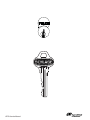
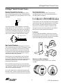
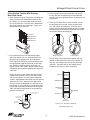
SFIC Service Manual
Table of Contents
Schlage® Small Format Cores ............................................................3
Everest Patented Key Control............................................................3
Key Control Summary .......................................................................3
Non-Patented Cores ..........................................................................3
Locksets ............................................................................................3
Mortise and Rim Cylinders ................................................................3
If You Are Familiar With Pinning Best Style Cores .............................4
Schlage SFIC Keys............................................................................4
If You Are Not Familiar With Pinning Best Style Cores ......................5
6-Pin Combinating Example (Tip to Bow)..........................................6
Cutting Keys ......................................................................................8
Key Blanks .........................................................................................8
Key Bitting Specifications ..................................................................8
Troubleshooting .................................................................................9
Service Equipment ..........................................................................10
Pin Kit Refills ...................................................................................10
SFIC Service Manual
SFIC Service Manual
Schlage® Small Format Cores
Schlage® Small Format Cores
Everest Patented Key Control
Non-Patented Cores
Most building owners have security problems due to
the unauthorized duplication of keys. Schlage Everest
keys are protected by U.S. utility patents 5,715,717 and
5,809,816.
To support key systems from other manufacturers,
Schlage offers 6-pin and 7-pin uncombinated cores in
the most popular IC keyways.
Patented
Undercut
Groove
A
C
D
DD
E
F
G
H
J
K
L
M
N
Q
R
TB
TD
These keyways are fully compatible and interchangeable
with keyways of the same letter designations from Arrow,
Best and KSP. Schlage and Arrow suffix the keyway
letter with “B”, the Best “A” keyway is ordered as “AB”.
The patented undercut groove requires a secondary
milling operation to make the key blank. It is a violation
of federal patent law for anyone other than Schlage to
manufacture and distribute these blanks. By replacing
standard cores with Everest patented key cores, end
users can be assured of a high level of key control.
Schlage also sells nickel silver key blanks with the Best
bow shape for all non-patented core keyways.
Locksets
An array of Schlage deadbolts, mortise locks and keyin-lever locksets are now available to accept SFIC cores.
Consult Schlage sales literature and your local distributor
for the latest offering of functions and finishes.
001425
Lip for patent protection
BW2
B
Key Control Summary
Most Everest B Family restricted keyways are for end
users who do their own key cutting. The keyway is used
for each job is registered to the end user by Schlage.
Everest restricted key blanks, cut keys and cores are
furnished only through authorized Schlage distributors
and then only when the end user attaches a letter of
authorization to the purchase order.
Restricted items are shipped directly to the end user
or a location specifically authorized by the end user.
Shipping the order prevents locksmiths and distributors
from having access to keys and cores without the
permission of the end user.
Mortise and Rim Cylinders
The Schlage SFIC mortise cylinder cams are easily
changed.
B234 and B235 restricted keyways are for locksmiths
and other security dealers who cut all keys for their end
user customers. Dealers must sign special key control
contracts to handle these keyways.
As a further deterrent to unauthorized key duplication,
Schlage stamps a facility code or locksmith ID number
on all keys and blanks to identify where they originated.
3
SFIC Service Manual
Schlage® Small Format Cores
If You Are Familiar With Pinning
Best Style Cores
Schlage SFIC Keys
Schlage keys use a shoulder stop against the plug face.
Most other brands of SFIC keys stop at the tip. Punchtype machines for other Best style keys will not work for
Schlage patented keys and vice-versa.
If you are already familiar with combinating Best style
cores to the A2 System (depths 0 through 9), you will
find no difference in combinating Schlage small format
cores. This applies to cores with Best Keyways as well
as the Everest patented keyway cores.
Shoulder Stop
In patented keyway cores, the blocking pin near the
front and to the right of the keyway checks for the lip of
material on the side of the key.
This pin does not participate in the combination of the
key and it remains safely inside the core during the
combinating process.
Like other brands of these small format cores,
the Schlage core should never be dismantled for
combinating or decombinating.
Tip Stop
If you already own a different brand of specialized pin
kit and tools for Best style cores, you may use them
for Schlage cores with the following exceptions and
cautions:
1. Do not use Arrow bottom pins because the bottom
flat is smaller and may not seat properly on a zero cut
when next to a 9.
2. Do not use Kaba Peaks® bottom pins as they are
.003” too short for Schlage cores.
3. For security reasons, Schlage advises against
using colored bottom pins. The colors can be read
through the keyway with a lock scope, revealing the
combination. They are also less resistant to wear
than nickel silver bottom pins.
4. Only the original Schlage 40-129 pin kit contains
the plug retainer, blocking pin and blocking pin
spring. The components normally do not need to be
replaced, but a supply may be needed to repair a
vandalized or worn core. These parts may be ordered
separately if you use a different brand of pin kit.
5. Due to the location of the blocking pin, the ejector
holes in the bottom of Schlage cores are all shifted
by .010” toward the back of the core. This may cause
problems in certain core decombinating fixtures and
presses. Using any brand of ejector pin should pose
no problems.
Schlage reserves the right to void the warranty if the
core is combinated with components that do not conform
to our specifications or if keys are improperly cut.
SFIC Service Manual
4
Schlage® Small Format Cores
3. Insert any key, turn the plug about 90° and remove
the key. Be sure the control lug remains extended,
leaving a clear passage down the pin chambers to the
plug surface.
If You Are Not Familiar With Pinning
Best Style Cores
1. Never remove the plug! These cores are designed
to be top loaded. All combinating is done strictly
by numbers as it is not possible to see any of the
pins at the shear line. Each pin size is determined
with simple addition and subtraction. There is no
opportunity for trial-and-error.
4. There are two shear lines in each chamber; one for
the operating keys (change, master, grand master,
etc.) and one for the control key. A build-up pin is
used to span the distance between the two. Its length
changes based on the difference between the control
key and the deepest operating key.
Top Pin
Build-up Pin
Master Pin
Bottom Pin
BU
BU
Operating Key
2. For all operating keys, have the bittings legibly
and neatly written. You can get bittings from the
bittings list or by gauging each key individually.
Each digit of the control key should be directly over
the corresponding digit of the master and change
key. With the control key bitting on the top, it is
helpful to draw a line under it in order not to confuse
control bittings with operating bittings during the pin
calculation.
Control Key
The pin stack is illustrated below, together with the
addition and/or subtraction necessary to determine
each pin. All chambers use exactly the same logic
and math. They differ only by the specific bitting
number of each key in a given cut position.
add
Top Pin enough to
total 23
Unless the core is cross keyed, you normally only
need three key bittings: control, TMK (top master
key) and change key. In most properly designed
systems, intermediate level master keys will operate
automatically. This is because each digit of their
bitting is usually contained either in the TMK or the
change key. If any master keys must operate which
have a digit not already contained in the change or
TMK, that digit must be written in the appropriate
position and pinned in.
control
plus
10
Build-up Pin
minus plug
total
deep op.
cut
minus
Master Pin
(if any) shallow op.
cut
Plug Total
shallow
Bottom Pin operating
cut
Check for unifor m
space here
Control lug
extended
Memorize:
Tur n plug
about 90
Control + 10 - Plug Total + Build Up
Total Stack Height = 23
5
SFIC Service Manual
Schlage® Small Format Cores
6-Pin Combinating Example (Tip to Bow)
5
3
1
1
0
6
2
2
9
1
3
3
4
6
6
0
2
0
0
2
7
5 A
5 AA
9 A1
Control
Grand Master
Master
Change
8
13
4
9
11
6
12
4
16
8
10
8
2
4
2
6
2
4
1
2
1
0
0
5
Chamber 1
Shallowest operating cut is 1
(= bottom pin)
Deepest minus shallowest is 2
(= master pin)
Formula of C + 10 - P = BU
5 + 10 - 3 = 12
We now have 1 + 2 + 12 = 15
“units of stuff” loaded.
8 (= top pin) must be added
to total 23
Chamber 3
Shallowest operating cut is 1
(= bottom pin)
Deepest minus shallowest is 2
(= master pin)
Formula of C + 10 - P = BU
9 + 10 - 3 = 16
We now have 1 + 2 + 16 = 19
“units of stuff” loaded.
4 (= top pin) must be added
to total 23
Chamber 5
Shallowest operating cut is 0
(= bottom pin)
Deepest minus shallowest is 2
(= master pin)
Formula of C + 10 - P = BU
2 + 10 - 2 = 10
We now have 0 + 2 + 10 = 12
“units of stuff” loaded.
11 (= top pin) must be added
to total 23
Chamber 2
Shallowest operating cut is 2
(= bottom pin)
Deepest minus shallowest is 4
(= master pin)
Formula of C + 10 - P = BU
0 + 10 - 6 = 4
We now have 2 + 4 + 4 = 10
“units of stuff” loaded.
10 (= top pin) must be added
to total 23
Chamber 4
Shallowest operating cut is 0
(= bottom pin)
Deepest minus shallowest is 6
(= master pin)
Formula of C + 10 - P = BU
4 + 10 - 6 = 8
We now have 0 + 6 + 8 = 14
“units of stuff” loaded.
9 (= top pin) must be added
to total 23
Chamber 6
Shallowest operating cut is 5
(= bottom pin)
Deepest minus shallowest is 4
(= master pin)
Formula of C + 10 - P = BU
7 + 10 - 9 = 8
We now have 5 + 4 + 8 = 17
“units of stuff” loaded.
6 (= top pin) must be added
to total 23
SFIC Service Manual
6
Schlage® Small Format Cores
5. Combinate one chamber completely before moving
on to the next. Think of each one as a simple math
problem which always has the answer of 23. Many
beginners try to install all seven bottom pins, then all
master pins, then all build-up pins, etc. This method
may seem easier but it forces you to think through
each “math problem” two or three times, rather
than once. Mistakes are more common with this
method. You will also never pick up any speed this
way and will usually have to write down all the pins
before combinating the core. Your goal should be to
calculate each chamber quickly in your head as you
build each stack.
You may prefer to install one cap and drive it into
place before installing the next. The jolt from the
mallet can cause loose caps to jump out of place.
Plastic or
Rawhide Mallet
Capping Tool
Cap
6. In a master keyed core, each chamber normally
has four pins. With the plug turned, you can watch
the top surface of each pin stack as you complete
it. The top surfaces should all line up evenly, about
.050” below the top surface of the core. Paying
attention to this detail lets you spot a pinning error
immediately and correct it before it’s too late.
Spring
7. With all chambers combinated, turn the plug back
to the 12 o’clock position so all the pin stacks can
fall into place. Caution: The bottom of the Schlage
keyway is very wide and open. Do not turn the plug
in a direction which would allow the pins to engage
in the bottom of the key slot.
10. Test all three keys (control, TMK and change key).
11. Spray a small amount of graphite into the keyway
and run a key in and out several times to work the
graphite through the core. This step is especially
important for Schlage patented cores. This is the
only way to lubricate the special side pin.
Pins fall
into keyway
Plug tur ned
too far
8. Add a very small amount of dry graphite into each
chamber. Do not overdo this or the springs will not
have room to compress properly.
9. Cap the core:
a. Slide the core into the capping block.
b. Install a spring into each chamber.
c. Slide cap on at the top of each chamber.
d. Chamber by chamber, press the capping tool
down and strike it sharply with a plastic or
rawhide mallet to press the cap all the way in and
seal the chamber. Never use a metal hammer. It
will eventually ruin your capping block and pin.
7
SFIC Service Manual
Schlage® Small Format Cores
SFIC Lubrication Instructions
Instrucciones para lubricación de SFIC
Instructions de lubrification du SFIC
1
2
Turn Core Upside Down
Gire el núcleo al revés
Tourner le barillet à l'envers
4
180˚
Scoop 56M" (60 mg) Graphite
Recoja 60 mg de grafito
Prendre le graphite de 60 mg
Scoop Graphite* With Key
Recoja grafito* con la llave
Prendre le graphite* à l’aide de la clé
5
Dump Graphite into Keyway
Vacíe el grafito en la agujero de la cerradura
Mettre le graphite dans le troude la serrure
*Superior® 4726 Natural Vein Graphite (or equivalent) recommended
*Se recomienda grafito Superior® 4726 de veta natural (o su equivalente)
*Graphite de veine naturelle Superior® 4726 (ou équivalent) recommandé
3
Place Graphite in Holes on Bottom of Core
Coloque el grafito en los agujeros al fondo del
núcleo
Placer le graphite dans les trous sur la partie
inférieure du barillet
6
7
SFIC Service Manual
8
Insert Key into Core
Inserte la llave en el núcleo
Insérer la clé dans le barillet
Rotate Key 360˚
Gire la llave 360˚
Tourner la clé 360˚
360˚
Schlage® Small Format Cores
Troubleshooting
Pin Lengths
If any key fails to operate the core you’ve just
combinated, review the bittings and try to ascertain
where the mistake may be. Hold the core upside down
and place the ejector tool into the hole of the chamber
you want to empty. Using a light plastic mallet, tap
the ejector tool until it forces all material out of the pin
chamber. Test all key(s) again.
Bottom Pins
0A = .110”
1A = .1225”
2A = .135”
3A = .1475”
4A = .160”
Ejector Tool
5A = .1725”
6A = .185”
7A = .1975”
8A = .210”
9A = .225”
Master, Build-up and Top
Pins
2B = .025”
3B = .0375”
4B = .050”
5B = .0625”
6B = .075”
7B = .0875”
If the problem persist, take your next best guess of
where the error is a repeat with another chamber.
When all keys operate, you know that the remaining
chambers are combinated correctly. Recombinate the
empty chambers. This technique is also used when it is
necessary to decombinate the core for rekeying.
8B = .100”
9B = .1125”
10B = .125”
11B = .1375”
If you find combinating difficult, we recommend
completely finishing one chamber at a time, including the
capping process, leaving the remaining chambers empty.
This allows you to test all keys chamber by chamber until
you build up enough accuracy and confidence to handle
all chambers at once.
12B = .150”
13B = .1625”
14B = .175”
15B = .1875” *
16B = .200”
17B = .2125” *
If keys fail to operate smoothly and you are positive you
have cut the keys and pinned the core correctly, your
key machine may be out of adjustment or pins may
have gotten mixed up in your pin kit. The A2 system pin
lengths and key bitting specs are shown on these pages.
You will need calipers or a micrometer to check your pins
and keys against the specs.
18B = .225”
19B = .2375”
*Not used in pure 2-step
progression.
Non-patented cores may be combinated to A3 or A4
system specifications, but these would be non-Schlage
key systems and are not within the scope of this manual.
9
SFIC Service Manual
Schlage® Small Format Cores
Cutting Keys
Key Bitting Specifications
The Schlage 40-071 is a special version of the Blue
Punch key machine for the Everest patented SFIC keys.
For service on this machine, contact Pro-Lok® at (714)
633-0681, fax (714) 633-0470.
Depths
0 = .3187”
1 = .3062”
2 = .2937”
3 = .2812”
4 = .2687”
5 = .2562”
6 = .2437”
7 = .2312”
8 = .2187”
9 = .2062”
To cut Schlage keys on a rotary cutter code machine,
it may be necessary to modify or replace the vise
jaw for reliable gripping. Contact your key machine
manufacturer directly.
1
1.096"
2
.946"
Code Card
3
.796"
C116
4
.646"
Since the Everest patented core is designed to replace
cores by Best, Arrow and others, Schlage’s key cuts are
read and written Tip to Bow. This is the opposite of other
Schlage keys, but standard for small format IC.
for HPC 1200 CM
Code Machine
5
.496"
6
.346"
7
.196"
.052
.056
Key Blanks
Everest SFIC
Key
Section
Facility Code
or
Locksmith ID
7
.988"
6
.838"
5
.688"
4
.538"
3
.388"
2
.238"
1
.088"
35-401
Schlage began to phase in the Everest bow (pictured
above) beginning in 2002. Earlier Everest SFIC key
blanks had the Classic Schlage key bow.
SFIC Service Manual
10
.054
Schlage® Small Format Cores
Service Equipment
Pin Kit Refills
NOTE: If you already own comparable Best style service
equipment by other manufacturers, you do not need to
invest in new equipment other than the key machine for
Everest patented keyway cores.
100/pack
Bottom Pins
0A = 34-800
1A = 34-801
2A = 34-802
3A = 34-803
4A = 34-804
5A = 34-805
6A = 34-806
7A = 34-807
8A = 34-808
9A = 34-809
Key Machine for Everest B Family Keys Only
40-071
Master, Build-up and Top
Pins
2B = 34-902
3B = 34-903*
4B = 34-904
5B = 34-905
6B = 34-906
7B = 34-907
8B = 34-908
9B = 34-909
A2 System Pin Kit
40-071
10B = 34-910
11B = 34-911
12B = 34-912
13B = 34-913
14B = 34-914
15B = 34-915*
16B = 34-916
9 8 7 6 5 4 3 2 1 0
A2 System Key Gage
40-128
Capping Block
40-137
17B = 34-917*
18B = 34-918
19B = 34-919*
*Not used in Schlage
systems
Capping Pin
40-138
Ejector Pin
40-136
11
SFIC Service Manual
NOTES
SFIC Service Manual
12
800.847.1864
www.schlage.com
©
Ingersoll-RandCompany
CompanyLimited
Limited SC-5292
MS-C62
© 2007
2007 Ingersoll-Rand
www.ingersollrand.com
Rev.
Rev. 10/07
12/07
Printed
PrintedininU.S.A.
U.S.A.