1
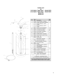
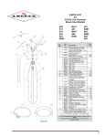
MAINTENANCE & RECHARGE
SERVICE MANUAL
NO. 05604
When maintenance is indicated, it should be performed by trained
persons having proper equipment. Fire extinguishers are pressure
vessels and must be treated with respect and handled with care. They
are mechanical devices and require periodic maintenance to be sure that
they are ready to operate properly and safely. Amerex strongly
recommends that the maintenance of portable fire extinguishers be done
by a trained professional – your local authorized Amerex Distributor.
Amerex Corporation makes original factory parts available to insure
proper maintenance – use of substitute parts releases Amerex of its
warranty obligations. Amerex parts have machined surfaces and
threads that are manufactured to exacting tolerances. O-rings, hoses,
nozzles, and all metal parts meet precise specifications and are
subjected to multiple in-house inspections and tests for acceptability.
There are substitute parts available that are incorrectly labeled as UL
component parts, some are advertised as Amerex type. None of these
meet UL requirements and all of them voids the Amerex extinguisher
warranty and UL listing. DO NOT SUBSTITUTE.
RECHARGE FIRE EXTINGUISHERS IMMEDIATELY AFTER ANY USE
REFERENCES IN THIS MANUAL:
NFPA-10 Portable Fire Extinguishers
AVAILABLE FROM:
National Fire Protection Association
1 Batterymarch Park, P.O, Box 9101
Quincy, MA 02269-9101
CGA C-1 Methods for Hydrostatic Testing of
Compressed Gas Cylinders
CGA C-6 Standard for Visual Inspection of
Compressed Gas Cylinders
Compressed Gas Association, Inc.
4221 Walney Road, 5th Floor
Chantilly, VA 20151-2923
AMEREX CORPORATION – P.O. BOX 81 – TRUSSVILLE, ALABAMA 35173-0081
Phone: 205/655-3271 Fax: 800/654-5980
e-mail: [email protected]
Web Page: http://www.amerex-fire.com
Printed in U.S.A.
0M05604G Rev. 2/12
HAND PORTABLE
HALON 1211 FIRE EXTINGUISHERS
All fire extinguishers should be installed, inspected and maintained in
accordance with the National Fire Protection Association standard titled
"Portable Fire Extinguishers", NFPA-10 and the requirements of local
authorities having jurisdiction.
AMEREX CORPORATION DOES NOT SERVICE, MAINTAIN OR RECHARGE FIRE EXTINGUISHERS. THIS
MANUAL IS PUBLISHED AS A GUIDE TO ASSIST QUALIFIED SERVICE PERSONNEL IN THE INSPECTION,
MAINTENANCE AND RECHARGE OF AMEREX FIRE EXTINGUISHERS ONLY. NO INSTRUCTION MANUAL
CAN ANTICIPATE ALL POSSIBLE MALFUNCTIONS THAT MAY BE ENCOUNTERED IN THE SERVICE OF FIRE
EXTINGUISHERS. DUE TO THE POSSIBILITY THAT PRIOR SERVICE PERFORMED ON THIS EQUIPMENT MAY
HAVE BEEN IMPROPERLY DONE, IT IS EXTREMELY IMPORTANT THAT ALL WARNINGS, CAUTIONS AND
NOTES IN THIS MANUAL BE CAREFULLY OBSERVED. FAILURE TO HEED THESE INSTRUCTIONS COULD
RESULT IN SERIOUS INJURY.
AMEREX ASSUMES NO LIABILITY FOR SERVICE, MAINTENANCE OR RECHARGE OF FIRE EXTINGUISHERS
BY PUBLISHING THIS MANUAL.
INSPECTING THE EXTINGUISHER
This extinguisher should be inspected at regular intervals (monthly or more often if
circumstances dictate) to insure that it is ready for use. Inspection is a "quick check" that a fire
extinguisher is available and is in operating condition. It is intended to give reasonable
assurance that the fire extinguisher is fully charged. This is done by verifying that it is in its
designated place, that it has not been actuated or tampered with, and that there is no obvious
physical damage or condition to prevent its operation.
PERIODIC INSPECTION PROCEDURES
(Monthly or more often if circumstances dictate)
[NFPA-10] Periodic inspection of fire extinguishers shall include a check of at least the following items:
1.
2.
3.
4.
5.
6.
7.
Location in designated place.
No obstruction to access or visibility.
Pressure gauge reading or indicator in the operable range or position.
Operating instructions on nameplate and facing outward.
Safety seals and tamper indicators not broken or missing.
Examination for obvious physical damage, corrosion, leakage, or clogged nozzle.
Fullness determined by weighing or "hefting"
MAINTENANCE
[NFPA-10] Extinguishers should be subjected to maintenance at intervals of not more than 1
year, at the time of hydrostatic test, or when specifically indicated by an inspection or electronic
notification. Maintenance procedures include a thorough examination of the basic elements of a
fire extinguisher:
1. Mechanical parts
2. Extinguishing agent of cartridge or cylinder operated extinguishers, pump tanks and certain types of
stored pressure extinguishers
3. Expelling means
NOTE: Stored pressure halon 1211 extinguishers do not require an internal examination of the
cylinder or examination of the agent during annual maintenance, but shall receive a thorough
external examination.
1
Maintenance [NFPA 10] is a thorough examination of the fire extinguisher. It is intended to give
maximum assurance that a fire extinguisher will operate effectively and safely. It includes a
thorough examination for physical damage or condition to prevent its operation and any
necessary repair or replacement. It will normally reveal if hydrostatic testing or internal
maintenance is required.
MAINTENANCE – SERVICE PROCEDURE
1.
Clean extinguisher to remove dirt, grease or foreign material. Check to make sure that the
instruction nameplate is securely attached and legible. Inspect the cylinders for corrosion,
abrasion, dents or weld damage. If any of these conditions are found and you doubt the
integrity of the cylinder, hydrostatically test to factory test pressure, using the proof pressure
method in accordance with CGA C-1 and C-6 and NFPA 10. See proper method of
depressurizing and reclaiming Halon 1211 in SIX-YEAR MAINTENANCE/RECHARGE
PROCEDURE.
Note: When cleaning, avoid use of solvents around the pressure gauge. They
could seriously damage the plastic gauge face.
2.
Inspect the extinguisher for damaged, missing or substitute parts.
parts are approved for use on Amerex fire extinguishers.
Only factory replacement
3.
Remove and check ring (safety) pin for freedom of movement.
removal appears difficult.
Replacement if bent or if
4.
Check the date of manufacture printed on the extinguisher label (nameplate). All stored
pressure Halon 1211 extinguishers must be hydrostatically (proof pressure) tested every 12
years.
5.
Visually inspect the pressure gauge:
a. If bent, damaged or improper gauge, depressurize and replace.
b. If pressure is low or high and temperature/pressure relationship has been ruled out:
1. If pressure is low, check for leaks.
2. If over pressurized (overcharged), depressurize the extinguisher and follow recharge
instructions.
6.
Inspect discharge lever for any dirt or corrosion which might impair freedom of movement.
Inspect carrying handle for proper installation. If lever, handle or rivets are damaged, replace
with proper Amerex part(s).
7.
Check weight of extinguisher and compare to proper weight specified on extinguisher
nameplate. If discrepancy is noted, remove nozzle or hose assembly and follow Complete
Maintenance/Recharge Procedure for recharging.
8.
Remove nozzle or hose and horn assembly. Inspect nozzle, hose gasket (o-ring), hose and
horn assembly for damage – replace as necessary. Blow air through hose and horn or nozzle
to insure passage is clear of foreign material and replace component parts as necessary.
9.
Inspect the valve assembly for corrosion or damage to hose thread connection. Replace valve
assembly or component parts as necessary following the proper recovery and recharge
procedures.
If valve removal is necessary, complete all steps in the Complete
Maintenance/Recharge Procedure.
10.
Install nozzle or hose and horn assembly.
11.
Install new tamper seal if broken and record service data on the extinguisher inspection tag.
12.
Replace the extinguisher on the wall hanger making sure that it fits the bracket properly –
replace the bracket if necessary.
2
COMPLETE MAINTENANCE – SIX YEAR TEARDOWN
[NFPA-10] Every six years, stored pressure extinguishers that require a 12 year hydrostatic test
shall be emptied and subjected to the applicable maintenance procedures. When the applicable
maintenance procedures are performed during periodic recharging or hydrostatic testing, the
six year requirement shall begin from that date.
WARNING:
a. Before attempting to delvalve the extinguisher for Maintenance, Hydrotest or Recharging
be sure that it is completely depressurized. Halon 1211 generates a vapor pressure of
22 psi @70°F. NEVER VENT TO THE ATMOSPHERE. Recover agent and vapor
according to the instructions below.
b. Never have any part of your body over the extinguisher while removing the valve
assembly.
c. Halon 1211 should not be mixed with even the slightest amount of moisture. Prolonged
exposure of a devalved cylinder to ambient air should be avoided to prevent moisture
contamination and cylinder rusting.
1. Complete items 1 through 9 in Maintenance/Service Procedure above.
2. Attach the appropriate recharge adapter to the extinguisher operating valve.
Empty the
extinguisher of all pressure and Halon 1211 using a Getz HR-1 (or UL approved equal) Halon
Recharge/Recovery system and a bulk Halon supply cylinder with sufficient empty capacity to
accept the contents of the extinguisher.
NOTE: Every effort should be made to halt unnecessary escape of Halon 1211 to
the atmosphere to prevent detrimental environmental effect. High efficiency
Halon 1211 Recharge/Recovery (Vacuum Pump Type) Systems (UL Standard 2006)
are commercially available. The Getz HR-1 (UL approved) unit assures a minimum
of 99% recovery efficiency. It allows a means of checking for and removing
moisture or contamination during the recovery process.
3. When the extinguisher is empty of all agent and pressure, remove valve assembly and
disassemble by removing downtube, spring and valve stem assembly.
assembly and collar o-ring.
Discard valve stem
NOTE: Keep cylinder opening covered while devalued to minimize interior
corrosion.
4. Thoroughly clean all parts of the disassembled valve with a soft bristle brush or soft cloth. Blow
5.
6.
7.
8.
9.
10.
the valve out with dry nitrogen.
Install a new Amerex valve stem assembly after lightly lubricating the valve stem o-ring with Visilox
711 (do not lubricate the valve stem seal). Reassemble the spring and downtube. Carefully install
a new collar o-ring which has been lightly lubricated with Visilox 711. Set the valve assembly
aside.
Inspect the cylinder interior following CGA Visual Inspection Standard C-6 and current NFPA 10
guidelines. If a hydrotest has been performed or any moisture is evident, the cylinder should be
immediately warm air dried.
Clean the o-ring seating groove in the cylinder neck. If any rust is evident, remove by using a fine
emery cloth (200 grit). Clean the surface and lubricate the entire sealing area with a thin film of
Visilox 711. Install the valve assembly in extinguisher cylinder. Hand tighten firmly.
Use the Getz HR-1 system to purge the residual air from the extinguisher cylinder.
Stand the extinguisher upright on a scale of sufficient size and capacity. Tare weight extinguisher
or record empty weight.
Follow all recharging instructions on Getz HR-1 or other UL Approved Recharge/Recovery system.
3
11. Remove the recharge adapter. Some residual Halon vapor may remain in the valve outlet as a
result of the charging procedure. Before attempting to leak detect, vacuum or blow the vapor away
from the areas to be checked. Check extinguisher for leaks at the valve outlet, around the collar
seal, cylinder welds and gauge using a Halogen Leak Detector (Preferred Method). The alternate
method is to apply leak detecting fluid or a solution of soapy water to these areas. Use dry
nitrogen to blow all liquid residue out of the valve and wipe the extinguisher to dry the exterior. DO
NOT LEAVE ANY LIQUID INSIDE THE VALVE BODY.
12. Install nozzle or hose and horn assembly to the extinguisher discharge valve.
13. Weigh extinguisher to confirm that the total weight is within the tolerances indicated in the
Maintenance section on the extinguisher nameplate.
14. Record service date and attach new tag in accordance with the requirements of the "Authority
Having Jurisdiction".
TROUBLESHOOTING GUIDE
WARNING: ANY HALON 1211 EXTINGUISHER MUST BE COMPLETELY DEPRESSURIZED
BEFORE ANY ATTEMPT IS MADE TO REMOVE THE VALVE AND CORRECT A LEAKAGE
PROBLEM.
To depressurize, see instructions in the Complete Maintenance section. Halon 1211 is a liquid
under nitrogen pressure. Variations in the temperature may affect gauge readings. The gauge
dial has been calibrated to reflect the tested extinguisher temperature extremes (-65°F to
+120°F). When in doubt about a gauge reading, place the extinguisher at room temperature
(70°F) for several hours to obtain a true reading.
PROBLEM
CORRECTIVE ACTION
1.
Leak at collar o-ring
Remove valve assembly, remove and discard o-ring,
clean collar thoroughly.
Install new collar o-ring.
Lubricate o-ring with Visilox V-711.
2.
Leak through valve
Check valve stem seating area for scratches or foreign
matter. Clean seating area with a tooth brush and soft
cloth. Install new valve stem assembly.
3.
Leak around gauge
Remove gauge*, clean threads and reinstall using Teflon
tape on the gauge threads.
4.
Defective gauge
Remove defective gauge* an install a new Halon 1211
gauge (see parts list) using Teflon tape on the gauge
threads.
5.
Leak in the cylinder
Contact Amerex if under warranty, otherwise mark
"REJECTED" and remove from service or return to
owner.
6.
Leak under operating lever
during discharge
Gauge indicator high or low
in green operable area, no
detectable temperature
leakage
Replace valve stem assembly.
7.
Extinguisher may have been subjected to extreme heat
or cold. Condition the extinguisher to room temperature
(70°F) overnight and check gauge reading.
* Pressure gauge threads are coated with a special epoxy at the factory. For easy
removal, soak the valve assembly in hot water (180°F) for two to four minutes.
Remove gauge with a thin 7/16" open end wrench.
4
PARTS LIST
for
1-1/4 - 20 lb. Halon 1211
Extinguisher Models
344
A344T
352
A352
C352TS
Item
No.
Part
No.
1
1A
11953
11954
06066
01727
01532
06978
06421
05180
05178
05176
05174
01412
16353
00160
00532
01387
01060
02625
07762
01563
04839
2
2A
2B
2C
2D
3
3A
3B
4
5A
5B
5C
5D
6
7
7A
7B
7C
7D
8
8A
9
9A
10
10A
11
11A
12
12A
13
14
14A
5
Description
354
A354
A354TS
C354
355
A355
B355T
369
B369
371
372
Std.
Pkg.
Valve Assembly – ALL ALUMINUM MODELS
1
Valve Assembly – ALL BRASS MODELS
1
Nozzle w/O-ring – 344/344T, A344T (.067)
6
Nozzle w/O-ring – 355T, A/B355T (.144)
Hose/Nozzle Gasket (O-ring) – Aluminum Valve
24
Hose Gasket (O-ring)
24
Hose & Horn Assembly – 354A, A354A, C354A (.098)
1
Hose & Horn Assembly – 369, B369 (.216)
Hose & Horn Assembly – 371, B371 (.234)
1
Hose & Horn Assembly – 361 (.152)
Hose & Horn Assembly – 372 (.177)
Ring Pin
24
Ring Pin 1 lb, 2-1/2 lb
Ring Pin, Stainless Steel
24
Chain (Nylon) for Ring Pin
24
Lockwire Seal (Yellow)
500
Rivet Only for Lever
24
Lever & Rivet
1
Lever & Rivet – Brass Valve
1
Rivet Only for Lever – Brass Valve
24
Gauge – 100 PSI – 344/344T, A344T
Gauge – 125 PSI – 352T, A/C352T,C352TS, 355T,
03105
A/B355T
6
Gauge – 195 PSI – 354A, A/C354A, 361, 369, B369,
03106
371, B371, 372
11826
Handle & Rivet – Brass Valve
1
01064
Rivet Only for Handle – Old & "A/B" Valve
24
09001
Handle & Rivet – 344/344T
24
09002
Handle & Rivet – Old Valve 352T, A354A, 355T
24
09020
Handle & Rivet – Brass Valve
1
01564
Rivets for Handle (2 Required) – Brass Valve
24
05241
Collar O-Ring – Aluminum Valve
24
Collar O-Ring – Aluminum Valve – Bulk Bag
100
05240
Collar O-Ring
24
Collar O-Ring – Bulk Bag
100
05235
Valve Stem O-Ring
24
05243
Valve Stem O-Ring – Brass Valve
24
06092
Valve Stem Assembly – Aluminum Valve
6
Valve Stem Assembly – Aluminum Valve – Bulk Bag
96
06093
Valve Stem Assembly – Brass Valve
6
Valve Stem Assembly – Brass Valve – Bulk Bag
96
01074
Spring – All Aluminum Valve
6
00383
Spring – All Brass Valve
6
06069
Downtube/Retainer Assembly – 344/344T, A344T
Downtube/Retainer Assembly – 352T, 354A,
01075
1
A/C352T, C352TS, A/C354T
06212
Downtube/Retainer Assembly – 355T, A/B355T
03754
Downtube/Retainer Assembly – 369/B369
02609
Downtube/Retainer Assembly – 371, B371
1
01667
Downtube/Retainer Assembly – 361, 372
Strap & Clip Assembly (Black Plastic) 3/8" Hose
17207
354, A/C354
1
Strap & Clip Assembly (Black Plastic) ½" Hose
14778
361, 369, B369, 371, B371, 372
15363
Hanger Loop with Screw – B371
6
16694
Hanger Loop with Screw – B369, 361, 372
14220
Hanger Loop with Screw – Aluminum Valve
6
ALL BRACKETS – SEE BRACKET PAGE
ALL FILL & HYDROTEST ADAPTERS – SEE ADAPTER PAGE
ALL VALVE ASSEMBLIES INCLUDE VALVE BODY, GAUGE, LEVER & HANDLE