1
APT-1
Service Manual
APT-1 - Service Manual
Rev. 0604 110V
2
Table of contents
1.
System components and details
5
2.
General Maintenance and Inspections
6
3.
Spare parts replacement
7
4.
Installation of Stand Assembly
20
5.
Fault finding
21
6.
Spare Parts List
21
7.
List of Tool Types
22
NOTE: Design details may change without notice
APT-1 - Service Manual
Rev. 0604 110V
3
APT-1 - Service Manual
Rev. 0604 110V
4
1. SYSTEM COMPONENTS AND DETAILS
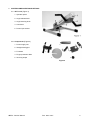
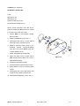
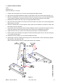
1.1. APT-1 unit (Figure 1)
1. Operator panel
2. Angle release knob
3. Angle securing knob
4. Crank-arm
5. Power input socket
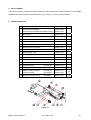
1.2. Components (Figure 2)
1. Power supply unit
2. Straight hand-grips
3. Footrests
4. Finger protection disks
5. Securing straps
Figure 2
APT-1 - Service Manual
Rev. 0604 110V
5
2. GENERAL MAINTENANCE AND INSPECTIONS
The rugged design of the Active Passive Trainer and the use of selected, modern materials ensure minimal
requirements for care and maintenance.
NOTE: Improper handling or neglect in the care of the Active Passive Trainer may reduce or cancel the
coverage of the manufacturer’s warranty.
2.1. Regular care
•
Inspect Power supply cables and plug for visible damages.
•
Check power-input connector for visible damage or insecure fastening.
•
On a regular basis check that all screws and components are fastened tightly.
•
Ensure that the anti-slip pads under the base are always kept clean.
CAUTION: If any damage is detected – do not use APT-1. Please contact your authorized dealer. Only
authorized personnel may carry out repairs.
2.2. Cleaning instructions
•
Disconnect Power Supply and wipe dry with clean cloth.
CAUTION: For safe disconnection of the APT-1 always take the mains plug out of the wall socket
before removing the connector from the APT-1 power socket.
•
Take care not to allow water to enter the unit. Keep cables and electric components away from water and humidity.
2.3. Storage
•
Store Active Passive Trainer between –20 and +40 degrees C and between 10% and 80% humidity
APT-1 - Service Manual
Rev. 0604 110V
6
3. REPLACEMENT INSTRUCTIONS
CAUTION: Disconnect Power Supply unit before replacement of any part of the APT-1. For safe disconnection of the APT-1 always take the mains plug out of the wall socket before removing the connector from the
APT-1 power socket.
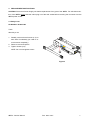
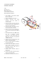
3.1. Body Cover
Kit Number: A0-00-1-001
Tools:
Allen Key 2 mm
1. Partially unscrew three Screws (3-A) on
each side of underbody (no need to remove screws completely)
2. Remove cover and replace
3. Tighten Screws (3-A)
NOTE: Do not over-tighten screws
Figure 3
APT-1 - Service Manual
Rev. 0604 110V
7
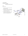
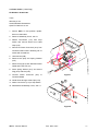
3.2. Control Panel
Kit Number: A0-00-1-005
A0-00-1-006 (for remote control)
Tools:
Allen Key 2 mm
1. Remove four Screws (4-A) from each
side of Control Panel
PA
SS
IV
E
MO
2. Gently pull out Panel and disconnect
AC
TIV
E
DE
Flat Cable Connector (4-B) from socket
on rear side of Control Panel
3. Connect Flat Cable securely to new
Control Panel and replace Screws (4-A)
NOTE: Do not over-tighten Screws
Figure 4
APT-1 - Service Manual
Rev. 0604 110V
8
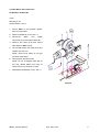
3.3. Gear Motor with crank-arms
Kit Number: A0-00-1-003
Tools:
Allen Key 2 mm
Socket Wrench 10 mm
1. Secure APT-1 in flat position upsidedown on clean table
2. Remove Underbody cover, see 3.1
3. Disconnect
Motor
wire
spade
connectors (5-A) from Motor terminals
4. Remove four Nuts (5-B) that secure
Gear Motor to APT-1 body.
5. Lift out Gear Motor with crank-arms and
replace with new one.
NOTE: Ensure that Wires do not get
'pinched' under Motor.
6. Secure Motor with Nuts (5-B).
NOTE: Do not overtighten Nuts (B) as
this may detach Studs from body or
cause paint on top of Body to crack.
7. Reassemble Underbody Cover, see 3.1
Figure 5
APT-1 - Service Manual
Rev. 0604 110V
9
3.4. Controller Circuit Board
Kit Number: A0-00-1-004
Tools:
Allen Key 2 mm
Allen "T"-Key 2.5 mm
Small Flat Blade Screwdriver
Silicone Heat-sink Compound
1. Secure APT-1 in flat position upsidedown on clean table.
2. Remove Underbody cover, see 3.1
3. Carefully
Connector
disconnect
(6-A)
Flat
from
Cable
socket
on
Controller board.
4. Disconnect Power Connector (6-B) from
Controller Board while releasing tab of
Socket (6-C) with screwdriver.
5. Disconnect Motor wire Spade Connectors (6-D) from Motor Terminals.
6. Remove Screws (6-E) and Washers (6-
Figure 6
F) connecting Controller Board to APT-1
body.
7. Lift Controller Board from APT-1 body
with
aid
of
screwdriver.
Silicone
compound is used between board and
APT-1 body – take care not to get hands
or APT-1 parts dirty.
8. Replace with new Controller board. Add
Silicone compound if needed.
9. Secure Controller Board with Washers
(6-F) and Screws (6-E)
10. Connect Motor wire Spade Connectors
(6-D) to Motor Terminals: red wire to
positive/red
terminal,
black
wire
to
negative/black terminal
11. Connect Power Connector (6-B) to
Socket (6-C)
12. Connect Flat Cable Connector (6-A) to
socket on Controller board
13. Reassemble Underbody Cover, see 3.1
APT-1 - Service Manual
Rev. 0604 110V
10
3.5. Power Cable (+ Male Plug)
Kit Number: A0-00-1-007
Tools:
Allen Key 2 mm
Small Flat Blade Screwdriver
Open End Wrench 19 mm
1. Secure APT-1 in flat position upsidedown on clean table.
2. Remove Underbody Cover, see 3.1
3. Detach Connectors (7-A) from Stop
Switch and remove Wires from Cable
Clips (7-B)
4. Disconnect Power Connector (8-A) from
Controller Board while releasing tab of
socket with screwdriver.
5. Unscrew Nut (8-B)
6. Remove Nut (8-B) and Spring Washer
(8-C)
7. Remove Plug (8-D) with attached Power
Cable and insert new one
8. Place Spring Wacher (8-C) and secure
Plug (8-D) with Nut (8-B)
Figure 7
9. Connect Power Connector (8-A) to
Controller Board
10. Guide Wires through Cable Clips (7-B)
11. Attach Connectors (7-A) to Stop Switch
12. Reassemble Underbody Cover, see 3.1
Figure 8
APT-1 - Service Manual
Rev. 0604 110V
11
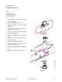
3.6. Stop Switch
Kit Number: A0-00-1-034
Tools:
Allen Key 2 mm
Flat Blade Screwdriver
Long Nosed Pliers
1. Secure APT-1 in flat position upsidedown on clean table
2. Remove Underbody Cover, see 3.1
3. Disconnect Wires (9-A) from Power
Cable (9-B)
4. Open Retaining Spring (9-C) slightly and
remove Stop Switch Body
NOTE: Be careful not to remove Spring
(9-C) from its Housing
5. Unscrew Nut (9-E) with Long Nosed
Pliers
6. Remove Knob (9-G) and Washer (9-F)
and insert new one
7. Secure Knob (9-G) with Nut (9-E)
8. Place Stop Switch Body and secure it
with Retaining Spring (9-C)
9. Connect Wires (9-A) to Power Cable (9B)
10. Reassemble Underbody Cover, see 3.1
Figure 9
APT-1 - Service Manual
Rev. 0604 110V
12
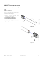
3.7. Base Support
Kit Number: A0-00-1-022 (Rear Base Support)
A0-00-1-023 (Front Base Support)
Tools:
Phillips #1 Screwdriver
Figure 10 shows Rear Base Support, Figure
11 shows Front Base Support
1. Remove
Screw
(10/11-A)
from
underside of Base Support
2. Pull off Support from Base tube
3. Replace with new Base Support
4. Secure
Base
Support
with
Screw
(10/11-A)
Figure 10
Figure 11
APT-1 - Service Manual
Rev. 0604 110V
13
3.8. Base (incl. Supports)
Kit Number: A0-00-1-024
Tools:
Allen Key 2 mm
Allen Key 5 mm
Open End Wrench 13 mm
Loctite Adhesive #242 (1312)
NOTE: These instructions can also be followed to transfer an APT-1 unit from a base
to a stand or the other way round.
1. Secure APT-1 in flat position upsidedown on table
2. Remove Underbody cover, see 3.1
3. Hold Nylock Nut (12-A) on inner side of
Securing Knob (12-B) with wrench
4. Remove Securing Knob (12-B) by unscrewing
(turning
counter-clockwise)
from Nut (12-A) and APT-1 body and
remove Washer (12-C)
NOTE: Keep parts for reassembly
5. Open Axis Nuts (12-C) on each side of
Figure 12
APT-1 and remove. Base can now be
separated from Body
6. Assemble new Base on Body
7. Secure assembly with Axis Nuts (12-D)
8. Place Washer (12-C) on Securing Knob
(12-B)
9. Hold Nylock Nut (12-A) with wrench and
screw Securing Knob (12-B) on Nut
10. Reassemble Underbody Cover, see 3.1
APT-1 - Service Manual
Rev. 0604 110V
14
3.9. Body Assembly
Kit Number: A0-00-1-026
Tools:
Allen Key 2 mm
Allen "T"-Key 2.5 mm
Allen Key 5 mm
Small Flat Blade Screwdriver
Socket Wrench 10 mm
Open End Wrench 13 mm
Silicone Heat-sink Compound
Loctite Adhesive #242 (1312)
1. Remove following parts as described
above:
a. Control Panel assembly
b. Under-body cover
c.
Gear Motor with crank-arms
d. Controller circuit board
e. Base from APT-1 body
2. Assemble components to new body in
opposite order.
APT-1 - Service Manual
Rev. 0604 110V
15
3.10.
Cable + Pulley for Stand
Kit Number: A0-00-1-043 – Cable & Pulley
Kit Number: A0-00-1-049 – Trolley
Tools
Allen Key 5 mm
Omnifit M100 Adhesive
Rod 130 cm with securing clip
Wrench 10 mm
Open End Wrench 17 mm
1. Remove APT-1 from Stand, see instruction 3.8
2. Open four Screws (13-A) and remove
Transformer (13-B)
3. Open three Screws (13-C) and remove
Transformer Holder (13-D)
4. Carefully remove Cable (13-E) from
Stud (13-F) and prevent it from being
pulled in Stand, see Figure 14
5. If necessary, remove Pulley (13-G) and
replace by new one
NOTE: When Cable does not need be replaced, reassemble Transformer, see instruction 16 and onwards
6. Lead Cable (13-E) carefully into Stand
CAUTION: The Cable is connected to a
Figure 13
powerful Spring (13-H) that will pull it
inwards; be careful when releasing Cable into Stand
7. Open Nut (13-L) on one side and remove Rod (13-K)
8. Remove Cable (13-E) from Hook (13-M)
9. Pull out Tube (13-J) and Spring (13-H)
Figure 14
with Cable (13-E)
10. Attach new Cable (13-E) to Hook (13-M),
insert other end with Spring (13-H) in
Stand and pull out on other side
11. Insert long Rod (15-A) (must be at least
130 cm long) with Securing Clip (15-B)
in Stand and attach it to Cable
Figure 15
APT-1 - Service Manual
Rev. 0604 110V
16
12. Gently pull Cable (13-E) in Stand, while
Tube (13-J) is inserted in Spring (13-H),
see also Fig. 3
13. Align Tube (13-J) with hole in Stand insert Rod (13-K) and secure with Nut (13L)
14. Ensure that Trolley (13-N) is in its lowest
position (closest to Spring)
NOTE: Attaching the Cable to the Trolley when it is in its top position seems
easier but will give trouble later during
use
15. Pull Cable (13-E) out of Stand by using
the long rod
16. Attach eye of Cable (13-E) to Stud (13F); ensure that Cable (13-E) runs
smoothly over Pulley (13-G) and that the
eye of Cable (13-E) sits secure over
Stud (13-F)
17. Secure Transformer Holder (13-D) to
Trolley (13-N) with three Screw (13-C)
18. Place Transformer (13-B) on Holder (13D) and secure with four Screws (13-A)
19. Reassemble APT-1 on Stand
APT-1 - Service Manual
Rev. 0604 110V
17
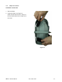
3.11.
Straps for Footrest
Kit Number: A0-00-1-050
1. Remove Straps
2. Insert new Straps, see Figure 16
NOTE: Ensure that the 50 cm strap is in
the rear slots and the 40 cm strap in the
front slots
Figure 16
APT-1 - Service Manual
Rev. 0604 110V
18
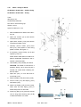
4. INSTALLATION OF STAND
Tools:
Allen Key 5 mm
Open End Wrench 17 mm (2x)
1. Insert the four floor guides (17-F) into the Left and Right Hand Base Frames
2. Align the Left and Right Hand Base Frames on either side of the Front Vertical Frame (see Fig. 16)
3. Slide the Threaded Bar on the Front Vertical Frame into the front hole (17-A) of the Left Hand Base
Frame, place the Washer in position and screw on the Cap Nut (do not tighten at this stage)
4. Repeat this procedure with hole (17-B) on the Right Hand Base Frame
5. Align the holes at the bottom of the Rear Vertical Frame with rear holes in the Left and Right Hand
Base Frames (17-D & E)
6. Slide the Threaded Bar (17-G) through the holes, place the two Washers in position on either side
and screw on the two Cap Nuts
7. Tip the Rear and Front Vertical Frames enough towards the back to slide the two tongues at the top
of the Rear Vertical Frame into the top of the Front Vertical Frame. Straighten both frames
8. Tighten the set screw (17-C) with a 5 mm Allen Key by turning it in a clockwise direction
9. Ensure that all frame members are aligned correctly and finally tighten all four Cap Nuts using two
17 mm open end wrenches
10. Adjust the four floor guides (17-F) to level and stabilize the base
11. Adjust height of APT by releasing the locking pin on the left hand side; secure positioning by tightening the knob on the right hand side
NOTE: Inside the Vertical Frame is a spring that pulls the APT upwards.
Figure 17
APT-1 - Service Manual
Rev. 0604 110V
19
5. FAULT FINDING
Tzora Active Systems provides for profound training in Fault Finding to the major distributors of the APT-1.
Please contact the authorized Tzora Distributor in your country or Tzora for more information.
6. SPARE PARTS LIST
Description
Part Number
Control Panel Assembly
A0-00-1-005
Control Panel Assembly for Remote Control
A0-00-1-006
2
Body Cover
A0-00-1-001
7
3
Gear Motor with Crank-arms
A0-00-1-003
9
4
Controller Circuit Board
A0-00-1-004
10
5
Rear Base Support
A0-00-1-022
13
6
Front Base Support
A0-00-1-023
13
7
Base (including Supports)
A0-00-1-024
14
8
Body Assembly
A0-00-1-026
15
9
Power Supply 110V
A0-00-1-016
-
9a
Power Supply 110V for Stand
A0-00-1-017
-
10
Stop Switch
A0-00-1-034
12
11
Remote Control
(not shown)
A0-00-1-018
-
12
Power Cable (+ male plug)
(not shown)
A0-00-1-007
11
13
4P Female Plug
(not shown)
A0-00-1-020
-
14
Finger protection disks
(not shown)
A0-00-1-025
-
15
Cable + Pulley for Stand
(not shown)
A0-00-1-043
Trolley for Stand
(not shown)
A0-00-1-049
Straps for Footrest (Pair)
(not shown)
A0-00-1-050
1
16
Page
8
16
18
Figure 18
APT-1 - Service Manual
Rev. 0604 110V
20
7. LIST OF TOOL TYPES
Screwdrivers:
Phillips #1
Flat Blade
Small Flat Blade
Allen Keys:
2 mm
2.5 mm ("T"-Key)
5 mm
Wrenches:
Socket Wrench 10 mm
Open End Wrench 13 mm
Open End Wrench 19 mm
Other Tools:
Long Nosed Pliers
Loctite Adhesive #242 (1312)
Silicone Heat-sink Compound
APT-1 - Service Manual
Rev. 0604 110V
21
For safety and for warranty assurance reasons, any modifications and repair of the APT-1 or its components
must be performed exclusively by authorized personnel and exclusively with original spare parts.
The APT-1 Active Passive Trainer and its accessories have been designed and manufactured in accordance
with the specification of the following:
DIRECTIVE: Medical devices 93/42 EEC (Annex V)
Manufactured by:
Distributed in USA by: Lifestyle Sports 10247 Lakeside Blvd Ext, Dunkirk, NY 14048
1-800-666-9198 716-679-7716 Fax 716-679-7718 [email protected] APT-trainers.com
APT-1 - Service Manual
Rev. 0604 110V
22