1
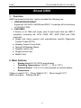
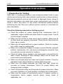
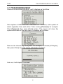
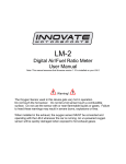
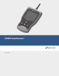
VW/AUDI/SKODA/SEAT/ CAN OBDII
U600
Table of Contents
Safety Precautions…………….……….…………..…………..2
About U600……….………..…………………………….……..4
1. Function…………………..……….……………………….…..4
2. Main features………………….…..…………….……………4
3. Appearance and Key Descriptions………………….……….4
Operation Instructions……………….....……………………..6
1. Preparation for Testing…………….………….……………..6
2. Connect the U600……………….…………..……………….7
3. Diagnose………………..…………..…..…………...…………7
3.1 VW/AUDI/SKODA/SEAT………………….………….…8
3.2 CAN OBDII.………..………….…………………..……..9
4. Contrast value adaptation………………………………..….25
5. Lcd test…………………..………………………………...….25
6. Key testing…………………………………………………….25
7. About…………………………………………………………..26
8. Location of Data Linking Connection……………………….26
1
VW/AUDI/SKODA/SEAT/ CAN OBDII
U600
Safety Precautions
To avoid body hurt and damage to the device or your car, please read
this manual carefully before using U600.
The general testing process described in this manual is got by technologist
of experience. Safety precaution is required in most of the process to avoid
body hurt and damage to the device or your car. Prior to your using this
device, please read vehicle maintenance code and follow the safety
precautions. Keep mention to the following general safety precautions.
z It generates CO and other poisonous air when engine run. To avoid
this kind of hurt, please repair the car in a well-air-ventilated location.
z To protect your eyes from the damage of the exposed objects, hot and
harmful liquid, please wear good eye-protection tools.
z When an engine is running, many parts (such as the coolant fan,
pulleys, fan belt etc.) turn at high speed. To avoid serious injury,
always be aware of moving parts. Keep a safe distance from these
parts as well as other potentially moving objects.
z Engine parts become very hot when the engine is running. To prevent
severe burns, avoid contact with hot engine parts.
z Before starting an engine for testing or trouble-shooting, make sure
the parking brake is engaged. Put the transmission in park (for
automatic transmission) or neutral (for manual transmission). Block the
drive wheels with suitable blocks.
z Connecting or disconnecting test equipment when the ignition is ON
can damage test equipment and the vehicle's electronic components.
Turn the ignition OFF before connecting the U600 to or disconnecting
the U600 from the vehicle’s Data Link Connector (DLC).
z To prevent damage to the on-board computer when taking vehicle
electronic measurements, please always use a digital multimeter with
at least 10meg Ohms of impedance.
z Fuel and battery vapors are highly flammable. To prevent an explosion,
keep all sparks, heated items and open flames away from the battery
and fuel / fuel vapors. DO NOT SMOKE NEAR THE VEHICLE
DURING TESTING.
z Don't wear loose clothing or jewelry when working on an engine.
Loose clothing can become caught in the fan, pulleys, belts, etc.
2
VW/AUDI/SKODA/SEAT/ CAN OBDII
U600
Jewelry is highly conductive, and can cause a severe burn if it makes
contact between a power source and ground.
3
VW/AUDI/SKODA/SEAT/ CAN OBDII
U600
1
About U600
1. Function
U600 has powerful function, mainly included the following two.
1.VW/AUDI/SKODA/SEAT.
Support all VW,AUDI, SKODA,and SEAT. It matches all the functions
of VAG1551/1552.
2.CAN OBDII.
It Works on all 1996 and newer cars & light trucks that are OBD II
compliant (including the VPW, PWM, ISO, KWP 2000 and CAN
protocols)
z Reads and clears generic and manufacturer specific Diagnostic
Trouble Codes (DTCs)
z Reading Freeze Frame Data
z Testing I/M Reading Status
z Reading vehicle info
z Oxygen sensor test
z Model 6 test
2. Main features
y
Display-Backlit LCD,128*64 pixel display.
y
Operating Temperature- 0 to 50℃ (﹣32 to 122℉)
y
External Power: 10.0 to 15.5 vols provided via vehicle battery
y
Dimensions:
195mm Length(7.76”) 81mm Width(3.16”) 32mm Height(1.27”)
OBDII connector , 1500mm(59.99”)
4
VW/AUDI/SKODA/SEAT/ CAN OBDII
U600
3. Appearance and Key Descriptions
The appearance of a U600 is as shown in the above figure.
1. LCD screen: 128*64
2. Enter key: confirm selection and enter
3. Esc key:
go back to the previous screens
4. up/down arrows: moves the selection pointer and scrolls up or down
5. LEFT/RIGHT arrows: move cursor.
6. Power button
7. Diagnostic extension cable: OBDII -16PIN
5
VW/AUDI/SKODA/SEAT/ CAN OBDII
U600
Operation Instructions
1. Preparation for Testing
U600 aids in monitoring electronic and emissions-related faults in your
vehicle and retrieving fault codes related to malfunctions in these systems.
Mechanical problems such as low oil level or damaged hoses, wiring or
electrical connectors can cause poor engine performance and may also
cause a “false” fault code. Fix any known mechanical problems before
performing any test. See your vehicle’s service manual or a mechanic for
more information.
Check the following areas before starting any test:
z Check the engine oil, power steering fluid, transmission fluid (if
applicable), engine coolant and other fluids for proper levels. Top off
low fluid levels if needed.
z Make sure the air filter is clean and in good condition. Make sure all
air filter ducts are properly connected. Check the air filter ducts for
holes, rips or cracks.
z Make sure all engine belts are in good condition. Check for cracked,
torn, brittle, loose or missing belts.
z Make sure mechanical linkages to engine sensors (throttle, gearshift
position, transmission, etc.) are secure and properly connected. See
your vehicle’s service manual for locations.
z Check all rubber hoses (radiator) and steel hoses (vacuum/fuel) for
leaks, cracks, blockage or other damage. Make sure all hoses are
routed and connected properly.
z Make sure all spark plugs are clean and in good condition. Check for
damaged, loose, disconnected or missing spark plug wires.
z Make sure the battery terminals are clean and tight. Check for
corrosion or broken connections. Check for proper battery and
charging system voltages.
z Check all electrical wiring and harnesses for proper connection. Make
sure wire insulation is in good condition, and there are no bare wires.
z Make sure the engine is mechanically sound. If needed, perform a
compression check, engine vacuum check, timing check (if
applicable), etc.
6
VW/AUDI/SKODA/SEAT/ CAN OBDII
U600
2. Connect the U600
2.1 Turn the ignition on.
2.2 Locate the vehicle's 16-pin Data Link Connector (DLC).
2.3 Connect the U600 cable connector to the vehicle’s DLC. Turn on the
ignition, Press [power button], The U600 will auto start, the following
screen will be displayed.
z
z
z
z
z
[Diagnose]: diagnose
[Contrast]: Contrast adaptation
[Lcd Test]: Lcd test
[Keypad Test]:Keypad test
[About]:show device version
3. Diagnose
Select [Diagnose] and then press [enter] key. The screen will display the
system selection menu as follow:
There are two powerful functions. VW/AUDI/SKODA/SEAT and CAN
OBDII. About how to operate, see the following.
7
VW/AUDI/SKODA/SEAT/ CAN OBDII
U600
3-1 VW/AUDI/SKODA/SEAT
Choose VW/AUDI/SKODA/SEAT and it displays as the follow.
Here system of U600 has been classified into 7 sections, each system of
which separates from each other. Take running [Common] for example.
Click [Common] then press [Enter] button. The screen will show the
systems that most of the cars share. It displays as the follow.
Now we can choose any one system. For example, to choose [01-Engine],
then press Enter] key. The screen will display the follow.
Later on, it will display if succeed.
8
VW/AUDI/SKODA/SEAT/ CAN OBDII
U600
Press [Enter] button or press Esc] button
If it fails it displays as the follow.
3-1.1 Read ECU version details
Choose [01-Controller Infor] and then press [Enter] button.The screen
will show you the version of the tool as the follow.
3-1.2 Read fault codes.
Choose [02-Fault Codes] and then press [Enter] button. The screen will
show fault codes. Move up or down key to check each fault code as the
follow.
9
VW/AUDI/SKODA/SEAT/ CAN OBDII
U600
3-1.3 Clear fault code
Choose [05-Clear Codes] then press [Enter] button as the follow.
You need to press [Enter] again to clear the fault codes. Meantime you
can also press [Esc] button to give up clearing fault codes. It shows as
the follow if succeeding in clearing the fault codes.
3-1.4 Read testing data value
Choose [08-Measure Blocks] and the press [Enter] button. See the
picture.
10
VW/AUDI/SKODA/SEAT/ CAN OBDII
U600
Press left or right key to select the number of place; while press up or
down key to input number. Press Enter] to confirm. See the picture.
3-1.5 Output testing
Select [03-Output Test] and then press [Enter] key. If this fails, it will
show the result as the following picture.
If successful, it will show as the follow.
3-1.6 Basic adaptation
Choose [04-Basic Settings] and then press [Enter] button.The operations
are similar to these of “3.4 Read Data Value”
3-1.7 Route adaptation
Choose [10-Adaptation] and then press Enter] button.The operations are
similar to these of “3.4 Read Data Value”
11
VW/AUDI/SKODA/SEAT/ CAN OBDII
U600
3-1.8 Coding
Choose [07-Coding] and then press [Enter] button.It shows as the follow.
Press left or right key to enter the number of places and press up or
down key to input the number. Press [Enter] to confirm.
When all finished, press [Enter].If succeeds, it will show as the following.
If it fails, it will show as the follow.
12
VW/AUDI/SKODA/SEAT/ CAN OBDII
U600
3-1.9 Login the system
Choose [16-Security Access] and then press [Enter] button. It shows the
following.
Press left or right button to choose the number of places while press up
or down key to input the pass code. After this, press [Enter] button to
login. If it succeeds, it will show as the follow.
If it fails, it shows the follow.
3-1.10 Advanced ID
Choose [1A-Advanced ID] and then press [Enter] key. It shows as the
follow.
13
VW/AUDI/SKODA/SEAT/ CAN OBDII
U600
Press [Esc] to login out.
3-1.11 System ready
Choose [15-Readiness] then press [Enter] button. If succeeds, it will
shows as the follow.
Press [Esc] to login out.
3-1.12 Functions for expert
Return to the main memu, choose [Diagnose] and then press [Enter].
Press right arrow to go to the next page. Choose [Special Function].
Press [Enter]. It will show the following.
3-1.12-1 Choose [Oil Reset] and then press [Enter] key. If failed
connecting, it will show as the follow.
14
VW/AUDI/SKODA/SEAT/ CAN OBDII
U600
If connects successfully, it will show the follow.
Press 0[Esc] to login out
3.1-12.2 Press [Srs Reset] and then press [Enter] key. If it fails
connecting, it shows as the follow.
If it connects successfully, it will read code as ordered before it returns
back. If fault codes found, it will show as the follow.
Here press [Enter] key. It will force the implement of reset command and
15
VW/AUDI/SKODA/SEAT/ CAN OBDII
U600
shows the follow when it succeeds.
If you don’t want to force the implementation of reset command, please
press [Esc] to draw out. After finishing code erasing, you can reset
airbag.
3-2 Choose CAN OBDII, it shows as the follow
It shows as the follow after you login the system successfully.
3-2.1 Read codes:
1. the trouble codes function read DTCs from the vehicle's computer
modules there tow types of codes, Malfunction Indicator Lamp(MIL)
Codes and pending codes
MIL Codes: These codes cause the computer to illuminate the MIL
when an emission related or drive ability fault occurs. The MIL is also
known as the “service Engine Soon” or “Check Engine Lamp”. MIL
codes remain in the vehicle’s memory until the fault is repaired.
2. Pending Codes: These codes are also referred as “continuous
16
VW/AUDI/SKODA/SEAT/ CAN OBDII
U600
monitor” and “maturing codes”. An intermittent fault will cause the
computer to store a code in memory. If the fault does not occur within
40 warm-up cycles, the code will be cleared from memory. If the fault
occurs a specific number of times, the code will mature into a DTC
and the MIL will turn on.
3. Select Trouble codes and press ENTER, The U600 retrives the DTCs
stored in the vehicle's computer modules.
▲if there are no trouble codes, it will display “No codes in the vehicle!”
▲If there are any trouble codes, all information will be reported on the
display
If there are over two fault codes, you can press up or down keys or
choose and read one.
If there is factory original fault codes, you can choose the corresponding
17
VW/AUDI/SKODA/SEAT/ CAN OBDII
U600
car model as to get the details of the fault code.
Take the “1)GM” for an example.
3-2.2 Erase codes
Select Erase Codes and press the ENTER key.
a message appears asking if you are want to erase all the fault codes.
If you Press ENTER
18
VW/AUDI/SKODA/SEAT/ CAN OBDII
U600
3-2.3 Live data
1. Display the live data,
2. All live data are reported on the display
Abbreviated Name for live data specified in Appendix A
3-2.4 Freeze Frame
1. When an emission-related fault occurs, certain vehicle conditions are
recorded by the on-board computer. this information is referred to as a
freeze.
19
VW/AUDI/SKODA/SEAT/ CAN OBDII
U600
Frame data. this data can be overwritten by faults with a higher priority.
2. If codes were erased, the freeze frame data may not be stored in
vehicle memory.
Select Freeze Frame from the menu and press ENTER
3. All Freeze Frame data are reported on the display
Abbreviated Name for Freeze Frame specified in Appendix A
3-2.5 IM Status
1. Select I/M Status and press ENTER
2. Using the UP/DOWN arrows to view status of the following monitors.
20
VW/AUDI/SKODA/SEAT/ CAN OBDII
U600
Abbreviated Name
-Misfire Monitor
-FUEL System Mon
-Com Component
-Catalyst Mon
-Htd Catalyst
-Evap System Mon
-Sec Air System
-A/C Refrig Mon
-OXYGEN Sens Mon
Oxygen Sens HTR
-EGR System Mon
Expanded Name
Misfire monitor
Fuel System Monitor
Comprehensive Components Monitor
Catalyst Monitor
Heated Catalyst Monitor
Evaporative System Monitor
Secondary Air System Monitor
Air Conditioning Refrigerant Monitor
Oxygen Sensor Monitor
Oxygen Heater Sensor Monitor
Exhaust Gas Recirculation System Monitor
3-2.6 Vehicle info
1. Select “Vehicle info” from the main menu, press the “ENTER” button.
2. Use the SCROLL button to view additional digits of the 17-digit string.
21
VW/AUDI/SKODA/SEAT/ CAN OBDII
U600
3. If the vehicle does not support this mode, a message will show " Not
supported!"
3-2.7 Oxygen Sensor
1. Select Oxygen Sensor and press ENTER
2. If the vehicle support this mode, data reported on the display. You can
select [Oxygen sensor location]
If the vehicle does not support this mode, a message will show " Not
supported!"
22
VW/AUDI/SKODA/SEAT/ CAN OBDII
U600
3. Select [Oxygen sensor test id]
Abbreviated Name
RichToLeSeThV(Con)
LeanToRiSeThV(Con)
LowSeVFoSwTiCA(Con)
HighSeVoFoSwTiCa(Con)
RichToLeSwTi(Cal)
LeanToRiSeSwTi(Cal)
MinSeVoForTeCy(Cal)
MaxSeVoForTeCy(Cal)
TimeBeSeTr(Cal)
Sensor period(Cal)
Expanded Name
Rich to lean sensor threshold voltage (constant)
Lean to rich sensor threshold voltage (constant)
Low sensor voltage for switch time calculation (constant)
High sensor voltage for switch time calculation (constant)
Rich to lean sensor switch time (calculated)
Lean to rich sensor switch time (calculated)
Minimum sensor voltage for test cycle (calculated)
Maximum sensor voltage for test cycle (calculated)
Time between sensor transitions (calculated)
Sensor period (calculated)
4. Display test result.
3-2.8 Model 6 Test
The purpose of this service is to allow access to the results for on-board
diagnostic monitoring tests of specific components / systems that are
continuously monitored (e.g., mis-firemonitoring) and non-continuously
monitored (e.g., catalyst system).
1. Select Model 6 Test and press ENTER
23
VW/AUDI/SKODA/SEAT/ CAN OBDII
U600
2. If your vehicle applies to ISO 9141-2, SAE J1850, and ISO 14230-4,
information will be reported on the display
3.
TID specified in Appendix B
4. If your vehicle applies to ISO 15765-4, information will be reported on
the display
5.
OBDMID and CID specified in Appendix C.
24
VW/AUDI/SKODA/SEAT/ CAN OBDII
U600
4. Contrast Adaptation
Choose [Contrast] at the main memu. Then press [Enter]. The screen will
display as the following.
Simply press up/down arrow to set and then press
[Enter] to
confirm.
5. Lcd test
Choose[Lcd Test] at the main memu, Press Enter],The screen will display
the following dynamic image.
When after testing, it will show “Test end!” as what the following shows.
6. Key testing
Choose [Keypad Test] at the main memu. Press [Enter]. The screen will
display the following interface.
25
VW/AUDI/SKODA/SEAT/ CAN OBDII
U600
Press any key then the screen will flash due to corresponding to your
cooperation. Double [Esc], you can withdraw from the testing.
7.About
Choose [About] and then press [Enter]. Then screen will display the version
of this tool.
8.Location of Data Linking Connection.
Refer to the picture of OBD-II 16pin as the following. For VW GOLF, it
locates in the right side of steering column; for Jetta, it locates in the left
side of the bottom of the dashboard which is at the driver’s ca; for Santana,
it locates the dust-proof gearbox which is in the front. For more details,
please refer to the vehicle repairing manual.
APPENDIX A
Abbreviated NAME FOR SERVICE $01 AND $02 SCALING AND
DEFINITION
Abbreviated Name
Fuel Sys1, Fuel Sys2
Expanded Name
Fuel system 1 status, Fuel system 1 status:
CALC LOAD
Calculated LOAD Value
COOLANT
Engine Coolant Temperature
ST FTRM1
Short Term Fuel Trim - Bank 1
LT FTRM1
Long Term Fuel Trim - Bank 1
26
VW/AUDI/SKODA/SEAT/ CAN OBDII
U600
ST FTRM2
Short Term Fuel Trim - Bank 2
LT FTRM2
Long Term Fuel Trim – Bank 2
FUEL PRES
Fuel Rail Pressure (gauge)
MAP
Intake Manifold Absolute Pressure
ENGINE
Engine RPM
VEH SPEED
Vehicle Speed Sensor
IGN ADV
Ignition Timing Advance for #1 Cylinder
IAT
Intake Air Temperature
MAF
Air Flow Rate from Mass Air Flow Sensor
ABSLT TPS
Absolute Throttle Position
SECOND AIR
Commanded Secondary Air Status
O2S Location
Location of Oxygen Sensors
O2S11
Bank 1 – Sensor 1
O2S12
Bank 1 – Sensor 2
O2S13
Bank 1 – Sensor 3
O2S14
Bank 1 – Sensor 4
O2S21
Bank 2 – Sensor 1
O2S22
Bank 2 – Sensor 2
O2S23
Bank 2 – Sensor 3
O2S24
Bank 2 – Sensor 4
SHRTFT11
Short Term Fuel Trim (Bank 1 – Sensor 1)
SHRTFT12
Short Term Fuel Trim (Bank 1 – Sensor 2)
SHRTFT13
Short Term Fuel Trim (Bank 1 – Sensor 3)
SHRTFT14
Short Term Fuel Trim (Bank 1 – Sensor 4)
SHRTFT11
Short Term Fuel Trim (Bank 2 – Sensor 1)
SHRTFT12
Short Term Fuel Trim (Bank 2 – Sensor 2)
SHRTFT13
Short Term Fuel Trim (Bank 2 – Sensor 3)
SHRTFT14
Short Term Fuel Trim (Bank 2 – Sensor 4)
OBD2 STAT
OBD requirements to which vehicle is designed
PTO STATUS
Power Take Off (PTO) Status
MI Dist. Traveled
Distance Travelled While MIL is Activated
O2S W.R.
EQ_RAT11
Bank 1 – Sensor 1 (wide range O2S) Equivalence Ratio (lambda)
O2S W.R.
B1,S1
Bank 1 – Sensor 1 (wide range O2S) Oxygen Sensor Voltage
O2S W.R.
EQ_RAT12
Bank 1 – Sensor 2 (wide range O2S) Equivalence Ratio (lambda)
O2S W.R.
B1,S2
Bank 1 – Sensor 2 (wide range O2S) Oxygen Sensor Voltage
O2S W.R.
EQ_RAT13
Bank 1 – Sensor 3 (wide range O2S) Equivalence Ratio (lambda)
O2S W.R.
B1,S3
Bank 1 – Sensor 3 (wide range O2S) Oxygen Sensor Voltage
O2S W.R.
EQ_RAT14
Bank 1 – Sensor 4 (wide range O2S) Equivalence Ratio (lambda)
O2S W.R.
B1,S4
Bank 1 – Sensor 4 (wide range O2S) Oxygen Sensor Voltage
O2S W.R.
EQ_RAT21
Bank 2 – Sensor 1 (wide range O2S) Equivalence Ratio (lambda)
O2S W.R.
B2,S1
Bank 2 – Sensor 1 (wide range O2S) Oxygen Sensor Voltage
O2S W.R.
EQ_RAT22
O2S W.R.
B2,S2
Bank 2 – Sensor 2 (wide range O2S) Equivalence Ratio (lambda)
Bank 2 – Sensor 2 (wide range O2S) Oxygen Sensor Voltage
27
VW/AUDI/SKODA/SEAT/ CAN OBDII
U600
O2S W.R.
EQ_RAT23
O2S W.R.
B2,S3
Bank 2 – Sensor 3 (wide range O2S) Equivalence Ratio (lambda)
O2S W.R.
EQ_RAT24
O2S W.R.
B2,S4
Bank 2 – Sensor 4 (wide range O2S) Oxygen Sensor Voltage //24-2b 0x1d
O2S W.R.
EQ_RAT11
Bank 1 – Sensor 1 (wide range O2S) Equivalence Ratio (lambda)
O2S W.R.
B1,S1
Bank 1 – Sensor 1 (wide range O2S) Oxygen Sensor Voltage
O2S W.R.
EQ_RAT12
Bank 1 – Sensor 2 (wide range O2S) Equivalence Ratio (lambda)
Bank 2 – Sensor 3 (wide range O2S) Oxygen Sensor Voltage
Bank 2 – Sensor 4 (wide range O2S) Equivalence Ratio (lambda)
O2S W.R.
B1,S2
Bank 1 – Sensor 2 (wide range O2S) Oxygen Sensor Voltage
O2S W.R.
EQ_RAT13
Bank 2 – Sensor 1 (wide range O2S) Equivalence Ratio (lambda)
O2S W.R.
B1,S3
Bank 2 – Sensor 1 (wide range O2S) Oxygen Sensor Voltage
O2S W.R.
EQ_RAT14
Bank 2 – Sensor 2 (wide range O2S) Equivalence Ratio (lambda)
O2S W.R.
B1,S4
O2S W.R.
EQ_RAT21
O2S W.R.
B2,S1
O2S W.R.
EQ_RAT22
O2S W.R.
B2,S2
O2S W.R.
EQ_RAT23
O2S W.R.
B2,S3
O2S W.R.
EQ_RAT24
O2S W.R.
B2,S4
O2S W.R.
EQ_RAT11
O2S W.R.
B1,S1
O2S W.R.
EQ_RAT12
O2S W.R.
B1,S2
O2S W.R.
EQ_RAT13
O2S W.R.
B1,S3
Bank 2 – Sensor 2 (wide range O2S) Oxygen Sensor Voltage
Bank 3 – Sensor 1 (wide range O2S) Equivalence Ratio (lambda)
Bank 3 – Sensor 1 (wide range O2S) Oxygen Sensor Voltage
Bank 3 – Sensor 2 (wide range O2S) Equivalence Ratio (lambda)
Bank 3 – Sensor 2 (wide range O2S) Oxygen Sensor Voltage
Bank 4 – Sensor 1 (wide range O2S) Equivalence Ratio (lambda)
Bank 4 – Sensor 1 (wide range O2S) Oxygen Sensor Voltage
Bank 4 – Sensor 2 (wide range O2S) Equivalence Ratio (lambda)
Bank 4 – Sensor 2 (wide range O2S) Oxygen Sensor Voltage
Bank 1 – Sensor 1 (wide range O2S) Equivalence Ratio (lambda)
Bank 1 – Sensor 1 (wide range O2S) Oxygen Sensor Current
Bank 1 – Sensor 2 (wide range O2S) Equivalence Ratio (lambda)
Bank 1 – Sensor 2 (wide range O2S) Oxygen Sensor Current
Bank 1 – Sensor 3 (wide range O2S) Equivalence Ratio (lambda)
Bank 1 – Sensor 3 (wide range O2S) Oxygen Sensor Current
O2S W.R.
EQ_RAT14
O2S W.R.
B1,S4
Bank 1 – Sensor 4 (wide range O2S) Oxygen Sensor Current
O2S W.R
EQ_RAT21
Bank 2 – Sensor 1 (wide range O2S) Equivalence Ratio (lambda)
O2S W.R
B2,S1
Bank 2 – Sensor 1 (wide range O2S) Oxygen Sensor Current
O2S W.R.
EQ_RAT22
Bank 2 – Sensor 2 (wide range O2S) Equivalence Ratio (lambda)
O2S W.R.
B2,S2
O2S W.R.
EQ_RAT23
Bank 2 – Sensor 3 (wide range O2S) Equivalence Ratio (lambda)
O2S W.R.
B2,S3
Bank 2 – Sensor 3 (wide range O2S) Oxygen Sensor Current
O2S W.R.
EQ_RAT24
O2S W.R.
B2,S4
O2S W.R.
EQ_RAT11
O2S W.R.
B1,S1
O2S W.R.
EQ_RAT12
O2S W.R.
B1,S2
O2S W.R.
EQ_RAT21
O2S W.R.
B2,S1
O2S W.R.
EQ_RAT22
O2S W.R.
B2,S2
Bank 1 – Sensor 4 (wide range O2S) Equivalence Ratio (lambda)
Bank 2 – Sensor 2 (wide range O2S) Oxygen Sensor Current
Bank 2 – Sensor 4 (wide range O2S) Equivalence Ratio (lambda)
Bank 2 – Sensor 4 (wide range O2S) Oxygen Sensor Current
Bank 1 – Sensor 1 (wide range O2S) Equivalence Ratio (lambda)
Bank 1 – Sensor 1 (wide range O2S) Oxygen Sensor Current
Bank 1 – Sensor 2 (wide range O2S) Equivalence Ratio (lambda)
Bank 1 – Sensor 2 (wide range O2S) Oxygen Sensor Current
Bank 2 – Sensor 1 (wide range O2S) Equivalence Ratio (lambda)
Bank 2 – Sensor 1 (wide range O2S) Oxygen Sensor Current
Bank 2 – Sensor 2 (wide range O2S) Equivalence Ratio (lambda)
Bank 2 – Sensor 2 (wide range O2S) Oxygen Sensor Current
28
VW/AUDI/SKODA/SEAT/ CAN OBDII
U600
O2S W.R
EQ_RAT31
Bank 3 – Sensor 1 (wide range O2S) Equivalence Ratio (lambda)
O2S W.R
B3,S1
Bank 3 – Sensor 1 (wide range O2S) Oxygen Sensor Current
O2S W.R.
EQ_RAT32
Bank 3 – Sensor 2 (wide range O2S) Equivalence Ratio (lambda)
O2S W.R.
B3,S2
Bank 3 – Sensor 2 (wide range O2S) Oxygen Sensor Current
O2S W.R.
EQ_RAT41
O2S W.R.
B4,S1
Bank 4 – Sensor 1 (wide range O2S) Equivalence Ratio (lambda)
O2S W.R.
EQ_RAT42
Bank 4 – Sensor 2 (wide range O2S) Equivalence Ratio (lambda)
O2S W.R.
B4,S2
Bank 4 – Sensor 2 (wide range O2S) Oxygen Sensor Current
Bank 4 – Sensor 1 (wide range O2S) Oxygen Sensor Current
APPENDIX B
This applies to ISO 9141-2, SAE J1850, and ISO 14230-4 definition for service $06.
TID(TEST ID SCALING DESCRIPTION)
$01 Rich to lean sensor threshold voltage (constant)
$02 Lean to rich sensor threshold voltage (constant)
$03 Low sensor voltage for switch time calculation (constant)
$04 High sensor voltage for switch time calculation (constant)
$05 Rich to lean sensor switch time (calculated)
$06 Lean to rich sensor switch time (calculated)
$07 Minimum sensor voltage for test cycle (calculated)
$08 Maximum sensor voltage for test cycle (calculated)
$09 Time between sensor transitions (calculated)
$0A Sensor period (calculated)
$0B-$1F reserved - to be specified by SAE and/or ISO
$21-$2F manufacturer Test ID description
$30-$3F manufacturer Test ID description
$41-$4F manufacturer Test ID description
$50-$5F manufacturer Test ID description
$61-$6F manufacturer Test ID description
$70-$7F manufacturer Test ID description
$81-$9F manufacturer Test ID description
$A1-$BF manufacturer Test ID description
$C1-$DF
manufacturer Test ID description
$E1-$FF manufacturer Test ID description
APPENDIX C
This only applies to ISO 15765-4 definition for service $06
OBDMID (ON-BOARD DIAGNOSTIC MONITOR ID) DEFINITION FOR SERVICE $06
OBDMID (Hex) On-Board Diagnostic Monitor ID name
00 OBD Monitor IDs supported ($01 - $20)
01 Oxygen Sensor Monitor Bank 1 - Sensor 1
02 Oxygen Sensor Monitor Bank 1 - Sensor 2
03 Oxygen Sensor Monitor Bank 1 - Sensor 3
04 Oxygen Sensor Monitor Bank 1 - Sensor 4
29
VW/AUDI/SKODA/SEAT/ CAN OBDII
U600
05 Oxygen Sensor Monitor Bank 2 - Sensor 1
06 Oxygen Sensor Monitor Bank 2 - Sensor 2
07 Oxygen Sensor Monitor Bank 2 - Sensor 3
08 Oxygen Sensor Monitor Bank 2 - Sensor 4
09 Oxygen Sensor Monitor Bank 3 - Sensor 1
0A Oxygen Sensor Monitor Bank 3 - Sensor 2
0B Oxygen Sensor Monitor Bank 3 - Sensor 3
0C Oxygen Sensor Monitor Bank 3 - Sensor 4
0D Oxygen Sensor Monitor Bank 4 - Sensor 1
0E Oxygen Sensor Monitor Bank 4 - Sensor 2
0F Oxygen Sensor Monitor Bank 4 - Sensor 3
10 Oxygen Sensor Monitor Bank 4 - Sensor 4
11 - 1F Reserved by document for future standardization
20 OBD Monitor IDs supported ($21 - $40)
21 Catalyst Monitor Bank 1
22 Catalyst Monitor Bank 2
23 Catalyst Monitor Bank 3
24 Catalyst Monitor Bank 4
25 – 30 Reserved by document for future standardization
31 EGR Monitor Bank 1
32 EGR Monitor Bank 2
33 EGR Monitor Bank 3
34 EGR Monitor Bank 4
35 - 38 Reserved by document for future standardization
39 EVAP Monitor (Cap Off)
3A EVAP Monitor (0.090")
3B EVAP Monitor (0.040”)
3C EVAP Monitor (0.020”)
3D Purge Flow Monitor
3E - 3F Reserved by document for future standardization
40 OBD Monitor IDs supported ($41 - $60)
41 Oxygen Sensor Heater Monitor Bank 1 - Sensor 1
42 Oxygen Sensor Heater Monitor Bank 1 - Sensor 2
43 Oxygen Sensor Heater Monitor Bank 1 - Sensor 3
44 Oxygen Sensor Heater Monitor Bank 1 - Sensor 4
45 Oxygen Sensor Heater Monitor Bank 2 - Sensor 1
46 Oxygen Sensor Heater Monitor Bank 2 - Sensor 2
47 Oxygen Sensor Heater Monitor Bank 2 - Sensor 3
48 Oxygen Sensor Heater Monitor Bank 2 - Sensor 4
49 Oxygen Sensor Heater Monitor Bank 3 - Sensor 1
4A Oxygen Sensor Heater Monitor Bank 3 - Sensor 2
4B Oxygen Sensor Heater Monitor Bank 3 - Sensor 3
4C Oxygen Sensor Heater Monitor Bank 3 - Sensor 4
4D Oxygen Sensor Heater Monitor Bank 4 - Sensor 1
30
VW/AUDI/SKODA/SEAT/ CAN OBDII
U600
4E Oxygen Sensor Heater Monitor Bank 4 - Sensor 2
4F Oxygen Sensor Heater Monitor Bank 4 - Sensor 3
50 Oxygen Sensor Heater Monitor Bank 4 - Sensor 4
51 - 5F Reserved by document for future standardization
60 OBD Monitor IDs supported ($61 - $80)
61 Heated Catalyst Monitor Bank 1
62 Heated Catalyst Monitor Bank 2
63 Heated Catalyst Monitor Bank 3
64 Heated Catalyst Monitor Bank 4
65 - 70 Reserved by document for future standardization
71 Secondary Air Monitor 1
72 Secondary Air Monitor 2
73 Secondary Air Monitor 3
74 Secondary Air Monitor 4
75 - 7F Reserved by document for future standardization
80 OBD Monitor IDs supported ($81 - $A0)
81 Fuel System Monitor Bank 1
82 Fuel System Monitor Bank 2
83 Fuel System Monitor Bank 3
84 Fuel System Monitor Bank 4
85 - 9F Reserved by document for future standardization
A0 OBD Monitor IDs supported ($A1 - $C0)
A1 Mis-Fire Monitor General Data
A2 Mis-Fire Cylinder 1 Data
A3 Mis-Fire Cylinder 2 Data
A4 Mis-Fire Cylinder 3 Data
A5 Mis-Fire Cylinder 4 Data
A6 Mis-Fire Cylinder 5 Data
A7 Mis-Fire Cylinder 6 Data
A8 Mis-Fire Cylinder 7 Data
A9 Mis-Fire Cylinder 8 Data
AA Mis-Fire Cylinder 9 Data
AB Mis-Fire Cylinder 10 Data
AC Mis-Fire Cylinder 11 Data
AD Mis-Fire Cylinder 12 Data
AE - BF Reserved by document for future standardisation
C0 OBD Monitor IDs supported ($C1 - $E0)
C1 - DF Reserved by document for future standardisation
E0 OBD Monitor IDs supported ($E1 - $FF)
E1 - FF Vehicle Manufacturer defined OBDM IDs
TID(STANDARDIZED TEST ID DESCRIPTION)
Range (Hex) Description
00 Reserved by document
01 Rich to lean sensor threshold voltage (constant)
31
VW/AUDI/SKODA/SEAT/ CAN OBDII
U600
02 Lean to rich sensor threshold voltage (constant)
03 Low sensor voltage for switch time calculation (constant)
04 High sensor voltage for switch time calculation (constant)
05 Rich to lean sensor switch time (calculated)
06 Lean to rich sensor switch time (calculated)
07 Minimum sensor voltage for test cycle (calculated)
08 Maximum sensor voltage for test cycle (calculated)
09 Time between sensor transitions (calculated)
0A Sensor period (calculated)
0B EWMA (Exponential Weighted Moving Average) misfire counts for last 10 driving cycles (calculated)
Calculation: 0.1 * (current counts) + 0.9 * (previous average)
Initial value for (previous average) = 0
0C Misfire counts for last/current driving cycles (calculated)
0D - 7F Reserved for future standardisation
32