1
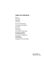
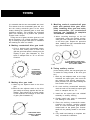
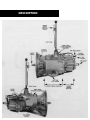
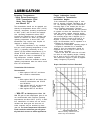
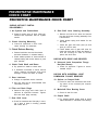
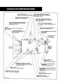
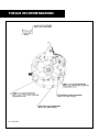
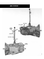
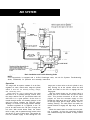
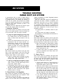
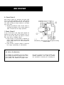
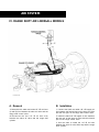
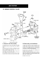
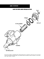
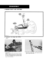
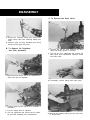
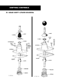
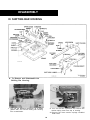
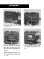
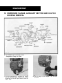
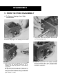
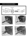
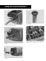
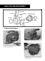
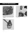
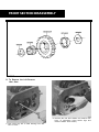
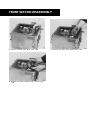
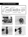
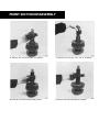
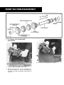
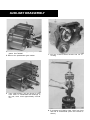
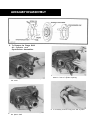
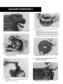
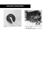
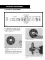
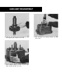
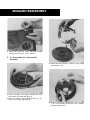
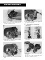
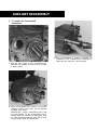
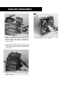
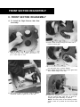
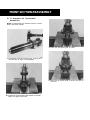
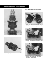
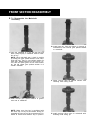
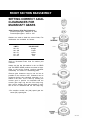
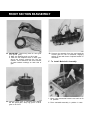
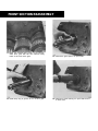
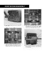
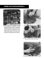
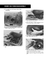
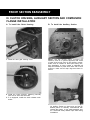
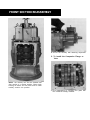
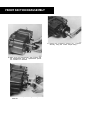
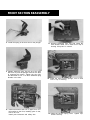
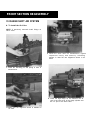
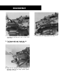
Service Manual
Fuller Heavy Duty Transmissions
TRSM0515
October 2007
TABLE OF CONTENTS
Timing
Description
Operations
Lubrication
Preventive Maintenance
Torque Recommendations
Air System
Precautions
Disassembly
Front Section Disassembly
Auxiliary Disassembly
Auxiliary Reassembly
Front Section Reassembly
Reassembly
Tool Reference
Changing Clutch (Input Shaft)
Eaton Corporation
Transmission Division
Kalamazoo, Mich. 49007
TIMIMG
It is essential that the two countershafts are timed.
This assures that the countershaft gears will contact the mating mainshaft gears at the same
instant, allowing the mainshaft gears to seek their
equilibrium position. This prohibits the mainshaft
gears from climbing out of position and prevents
unequal tooth contact.
Timing one set of gears, the drive gear set, is all
that is necessary. It is a simple procedure, consisting of marking the proper teeth prior to installation
and meshing the teeth so marked.
A. Marking countershaft drive gear teeth.
C. Meshing marked countershaft gear
teeth with marked drive gear teeth.
(After installing drive gear and mainshaft assemblies, the countershaft
bearings are installed to complete
countershaft installation.)
1. When installing bearings on the left
countershaft, mesh the marked countershaft gear tooth between two marked teeth
on the drive gear. Repeat the procedure
when installing the right countershaft bearings. (See Illustration C.)
1. Prior to placing each countershaft assembly into case, clearly mark on each drive
gear the gear tooth which is directly over the
keyway in gear. (See illustration A.) This
tooth is stamped with an "O" to aid identification.
C. COUNTERSHAFT GEAR TEETH
MESHED WITH DRIVE GEAR TEETH
FOR CORRECT TIMING
D. Timing auxiliary section.
A. TOOTH ON
COUNTERSHAFT
DIRECTLY OVER
KEYWAY MARKED
FOR TIMING
B. Marking drive gear teeth.
1. Mark any two adjacent teeth on the drive
gear.
2. Mark the two adjacent teeth on the drive
gear which are directly opposite the first set
marked. There should be an equal number
of teeth between the markings on each side
of gear. (See Illustration B.)
(In the auxiliary section, the low speed gear set
is marked for timing instead of the drive gear
set.)
1. Mark any two adjacent teeth on the large
mainshaft low speed gear, then mark the
two adjacent teeth directly opposite„the
same procedure as used when marking the
front section drive gear.
2. On each auxiliary countershaft assembly,
mark the tooth on the small low speed gear
which is stamped with an "O".
3. Install the low speed gear and tailshaft
assembly in auxiliary housing.
4. Partially install outer races of countershaft
rear bearings in case bores.
5. Place the auxiliary countershaft assemsemblies into position, meshing marked
tooth on each countershaft gear between
marked teeth on low speed gear. Countershafts will be partially seated in rear bearing.
Cut 7300A
B. DRIVE GEAR TEETH
CORRECTLY MARKED
FOR TIMING
6. Fully install rear bearings to complete auxiliary countershaft installation.
DESCRIPTION
OPERATION
SHIFTING THE
10 S P E E D R O A D R A N G E R
RT-661O SERIES
General Instructions
The 10-speed Roadranger Transmissions provide
ten selective ratios, evenly and progressively spaced and shifted with one lever. But you do NOT shift
the Roadranger as you would a conventional
transmission with an auxiliary or 2-speed axle,
because there is no split-shifting.
The shifting of the 10-speed Roadranger Transmissions is much simpler.. much easier,
ALL SHIFTS ARE MADE WITH ONE LEVER . . .
you use the RANGE CONTROL BUTTON ONE
TIME ONLY during a sequence of up-shifts . . .and
ONE TIME ONLY during a down-shift pattern.
Why is the Roadranger different?
The Roadranger is a 2-RANGE transmission consisting of a5-speed front section and an automatic
2-speed auxiliary section in ONE CASE. The ten
forward speeds are secured by using a 5-speed
shifting pattern TWICE–the first time with the
transmission engaged in Iow gear or low range; the
second time engaged in high gear or high range.
By using the same shifting pattern twice, the
TRANSMISSION
shift lever position for 6th speed is the same as
lst...7th the same as 2nd, 8th the same as 3rd, 9th
the same as 4th, and 10th the same as 5th.
Detailed Shifting Instructions
In the following instructions, it is assumed that the
driver is familiar with motor trucks and tractors,
and that he can coordinate the necessary
movements of the shift lever and clutch pedal to
make progressive and selective gear engagements
in either direction, up or down.
Upshifting
To get to high range
pull button UP while
in 5th speed, then
move lever to 6th
speed.
Let's step into the cab.
1. Move the gear shift
lever to the neutral position.
2. Start the engine.
3. Wait for air system to reach normal line
pressure.
4. Now look at the Range Control Button. If it is up
push it to the down position. (With the downward
movement of the button, the transmission will
shift into low range.) If the button was down when
the truck was last used, the transmission is
already in low range.
5. Now start the vehicle and shift progressively
through 1st, 2nd, 3rd and 4th to 5th.
6. When is 5th and ready for the next upward shift,
PULL the Range Control Button UP and move the
lever to 6th speed. As the Iever passes through the
neutral position, the transmission will automatically shift from low range to high range.
7. With the transmission in high range, you may
now shift progressively through 7th, 8th and 9th to
10th.
Driving tip: always start vehicle moving in first
speed gear.
A shift diagram should be in your vehicle. If your shift diagram has been misplaced, write
to Service Department, Eaton Corporation, Transmission Division, Kalamazoo, Michigan,
for replacement. Please specify model number of transmission.
OPERATION
Downshifting
To get to low range
push button DOWN
while in 6th speed,
then move lever to
5th speed.
1. When shifting down,
move the lever from 10th
through each successive lower speed to 6th.
2. When in 6th, and ready for the next downward
shift, PUSH the Range Control Button DOWN and
move the lever to 5th speed. As the lever passes
through the neutral position, the transmission will
automatically shift from high range to low range.
3. With the transmission in low range, shift down
ward through each of the four remaining steps.
Use Range Control Button only as described
Don't shift from high range to low range at high
speeds.
Don't make range shifts with the vehicle moving in
reverse gear.
For 7-speed shifting with medium-heavy loads
shift 2, 4, 6, 7, 8, 9, 10
For 8-speed shifting with heavy loads
shift 2, 4, 5, 6, 7, 8, 9, 10
Skip-shifting is easy, too
Skip-shifting is easy with the Roadranger transmission. Depending on the load, the RT-6610 can
be shifted as a 6, 7, 8, 9 or 10 speed transmission.
When you skip-shift going up make sure to pull
the range control "up" to high range before the
shift which passes 5th. Skip-shifting down, make
sure to push the range control down to low range
before the shift which passes 6th.
Following are some suggested skip-shifting patterns:
"Stop" sign or "Slow" sign
When slowing down for a
"stop" or "slow" sign, shift
down through the individual
short steps. By following this procedure the compression of the engine will slow the vehicle. The
life of chassis and trailer brakes can thus be prolonged.
Shifting the
®
Fuller RT & RTO-6610
®
Roadranger Transmissions
Ratios
Models
Ratios
Rev.
9.50
8.94 7.00 5.46 4.26 3.42 2.61 2.05 1.60 1.25 1.00 2.78
1st
For 6-speed shifting with light loads
shift 3, 5, 7, 8, 9, 10
RT-6610
2nd
3rd
4th
5th
6th
7th
8th
9th
RTO-6610 7.17 5.61 4.38 3.42 2.74 2.10 1.64 1.28 1.00
10th
.80
7.62
2.23
LUBRICATION
Proper Lubrication . . .
the Key to long
transmission life
Recommended Lubricants
Fahrenheit
(Celsius)
Grade
Ambient
Temperature
Type
(SAE)
®
Eaton Roadranger
CD50 Transmission
Fluid
Proper lubrication procedures are the key to a
good all-around maintenance program. If the
oil is not doing its job, or if the oil level is
ignored, all the maintenance procedures in the
world are not going to keep the transmission
running or assure long transmission life.
Eaton® Fuller ® Transmissions are designed
so that the internal parts operate in a bath of
oil circulated by the motion of gears and
shafts.
Thus, all parts will be amply lubricated if
these procedures are closely followed:
Mineral Gear Oil with rust
and oxidation inhibitor
API-GL-1
Eaton ® Roadranger ® CD50 Transmission Fluid
HIGHWAY USE
I
Factory fill
Initial drain,
Check fluid level.
Check for leaks.
Every 250,000 miles
(402336 Km)
I
I
Change transmission
fluid.
OFF-HIGHWAY USE
First 30 hours
I
I
Proper Oil Level
Make sure oil is level with filler opening. Because you can reach oil with your finger does
not mean oil is at proper level. One inch of oil
level is about one gallon of oil.
Change transmission fluid where
severe dirt conditions exist.
Every 1,000 hours
Change transmission fluid
(Normal off-highway use).
Heavy Duty Engine Lubricant or
Mineral Gear Lubricant
I
Factory fill
initial drain.
First 3,000 to 5,000 miles
(4827 to 8045 Km)
Every 10,000 miles
(16090 Km)
Inspect lubricant level.
Check for leaks.
Every 50,000 miles
(80450 Km)
Change transmission
lubricant.
OFF-HIGHWAY USE
Every 500 hours
Every 1,000 hours
Draining Oil
Drain transmission while oil is warm. To drain
oil remove the drain plug at bottom of case.
Clean the drain plug before re-installing.
Refilling
Clean case around filler plug and remove plug
from side of case. Fill transmission to the
level of the filler opening. If transmission has
two filler openings, fill to level of both openings.
The exact amount of oil will depend on the
transmission inclination and model. Do not
over fill—this will cause oil to be forced out
of the transmission,
When adding oil, types and brands of oil
should not be mixed because of possible incompatibility.
I
HIGHWAY USE
Every 40 hours
Above 1O”F,(-12”C.)
Below IO”F.(-12°C,)
Inspect fluid level, Check for leaks.
Every 500 hours
First 30 hours
Above 10”E(-12”C.)
Above 10”F.(-12”C,)
Below 1O”F,(-12”C,)
I
Factory fill
Initial drain.
Every 40 hours
I
90
80W
All
The use of mild EP gear oil or multi-purpose gear oil is not recommended, but if
these gear oils are used, be sure to adhere to
the following limitations:
Do not use mild EP gear oil or multi-purpose gear oil when operating temperatures are
above 230°F (110°C). Many of these gear oils,
particularly 85W140, break down above 230°F
and coat seals, bearings and gears with deposits that may cause premature failures. If
these deposits are observed (especially a coating on seal areas causing oil leakage), change
to Eaton Roadranger CD50 transmission fluid,
heavy duty engine oil or mineral gear oil to
assure maximum component life and to maintain your warranty with Eaton. (Also see
“Operating Temperatures”.)
Additives and friction modifiers are not recommended for use in Eaton Fuller transmissions.
Lubrication Change and Inspection
Every 10,000 miles
(16090 Km)
50
Heavy Duty Engine 011
50
MIL-L-2104B, C or D or
40
API-SF or API-CD
(Prewous API designations 30
acceptable)
1. Maintain oil level. Inspect regularly.
2. Change oil regularly.
3. Use the correct grade and type of oil.
4. Buy from a reputable dealer.
First 3,000 to 5,000 miles
(4827 to 8045 Km)
®
Change transmission
lubricant on new units.
Inspect lubricant level. Check for leaks,
Change transmission lubricant where
severe dirt conditions exist.
Change transmission lubricant
(Normal of highway use),
I
I
I
I
4
LUBRICATION
Operating Temperatures
—With Eaton® Roadranger ®
CD50 Transmission Fluid
Heavy Duty Engine Oil
and Mineral Oil
The transmission should not be operated consistently at temperatures above 250°F (120°C).
However, intermittent operating temperatures
to 300°F (149°C) will not harm the transmission. Operating temperatures above 250°F
increase the lubricant’s rate of oxidation and
shorten its effective life. When the average
operating temperature is above 250°F, the
transmission may require more frequent oil
changes or external cooling.
The following conditions in any combination can cause operating temperatures of over
250°F: (1) operating consistently at slow
speeds, (2) high ambient temperatures, (3) restricted air flow around transmission, (4) exhaust system too close to transmission, (5)
high horsepower, overdrive operation.
External oil coolers are available to reduce
operating temperatures when the above conditions are encountered.
Proper Lubrication Levels
as Related to Transmission
Installation Angles
If the transmission operating angle is more
than 12 degrees, improper lubrication can occur. The operating angle is the transmission
mounting angle in the chassis plus the percent of upgrade (expressed in degrees).
The chart below illustrates the safe percent
of upgrade on which the transmission can be
used with various chassis mounting angles.
For example: if you have a 4 degree transmission mounting angle, then 8 degrees (or 14
percent of grade) is equal to the limit of 12
degrees. If you have a O degree mounting
angle, the transmission can be operated on a
12 degree (21 percent) grade.
Anytime the transmission operating angle of
12 degrees is exceeded for an extended
period of time the transmission should be
equipped with an oil pump or cooler kit to
insure proper lubrication.
Note on the chart the effect low oil levels
can have on safe operating angles. Allowing
the oil level to fall 1/2" below the filler plug
hole reduces the degree of grade by approximately 3 degrees (5.5 percent).
Proper Lubrication Levels are Essential!
Transmission Oil Coolers are:
Recommended
— With engines of 350 H.P. and above
with overdrive transmissions
Required
— With engines 399 H.P. and above with
overdrive transmissions and GCW’S
over 90,000 lbs.
— With engines 399 H.P. and above and
1400 Lbs.-Ft. or greater torque
— With engines 450 H.P. and above
— With EP or Multipurpose Gear Oil
Mild EP gear oil and multipurpose gear oil are
not recommended when lubricant operating
temperatures are above 230°F (110°C). In addition, transmission oil coolers are not recommended with these gear oils since the oil
cooler materials may be attacked by these
gear oils. The lower temperature limit and oil
cooler restriction with these gear oils generally limit their success to milder applications.
Transmission Mounting Angle
Dotted line showing “2 Quarts Low” is for
reference only. Not recommended.
PREVENTATIVE MAINTENANCE
CHECK CHART
PREVENTIVE MAINTENANCE CHECK CHART
CHECKS WITHOUT PARTIAL
DISASSEMBLY
1. Air System and Connections
a. Check for leaks, worn air lines, loose connections and capscrews. See Air System
section.
2. Clutch Housing Mounting
a. Check all capscrews in bolt circle
clutch housing for looseness.
3. Clutch Release Bearing
a. Remove hand hole cover and check wear.
and axial clearance in release bearing.
b. Check relative position of thrust surface of
release bearing with thrust sleeve on push
type clutches.
4. Clutch Pedal Shaft and Bores
a. Pry upward on shafts to check wear.
b. If excessive movement is found, remove
clutch release mechanism and check
bushings in bores and wear on shafts.
5. Gear Lubricant
a. Change at specified service intervals.
b. Use only gear oils as recommended. See
Lubrication section.
6. Filler and Drain Plugs
a. Remove filler plugs and check level of
lubricant at specified intervals. Tighten
filler and drain plugs securely.
7. Gear Shift Lever
a. Check for looseness and free play in housing. If lever is loose in housing, proceed
with Check No. 8.
8. Gear Shift Lever Housing Assembly
a. Remove air lines at air valve and remove
the gear shift lever housing assembly from
transmission.
b. Check tension spring and washer for set
and wear.
c. Check the gear shift lever pivot pin and
pivot pin slot for wear.
d. Check bottom end of gear shift lever for
wear and check slot of yokes and blocks in
shift bar housing for wear at contact
points with shift lever.
CHECKS WITH DRIVE LINE DROPPED
9. Universal Joint Companion Flange
Nut (Not Shown)
a. Check for tightness. Tighten to recommended torque.
CHECKS WITH UNIVERSAL JOINT
COMPANION FLANGE REMOVED
1 0 . Splines on Output Shaft
a. Check for wear from movement and chucking action of the universal joint companion flange.
11. Mainshaft Rear Bearing Cover
a. Check oil seal for wear.
12. Output Shaft
a. Pry upward against output shaft to check
radial clearance in mainshaft rear bearing.
PREVENTATIVE MAINTENANCE
CHECK CHART
TORQUE RECOMMENDATIONS
TORQUE RECOMMENDATIONS
Cut 7191D-7/84
AIR SYSTEM
AIR SYSTEM
Basic Installation and Trouble Shooting Guide
NOTE:
If the transmission is equipped with a A-5010 Roadranger valve, see the Air Systems Troubleshooting
Guide, TRSM-0920, for operation and assembly instructions .
Operation
The range shift air system consists of an air filter,
regulator, air valve, control valve, range air cylinder
which is built into the auxiliary housing, fittings,
and connecting lines.
Range shifts can only be made when the gear
shift lever is in, or passing through, neutral. Thus,
the range desired can be pre-selected while the
shift lever is in a gear position. As the lever is
moved through neutral, an actuating plunger in the
shift bar housing releases the inter-lock piston
allowing it to move to the range position selected.
Constant regulated air is supplied to the "S"
port of air valve and to the "IN" port of range control valve. With control button down, the control
valve is open, and air passes through control valve
and to the "P" port of slave valve. This permits air
from the constant supply to flow through the low
range port in slave valve to the air cylinder in auxiliary housing. Air at the cylinder moves the shift
piston and shaft to the rear to engage the low
range gear.
With the control button up, the control valve is
closed, and air is removed from end port of slave
valve. This permits movement of the air valve
poppet; air from the constant supply to flow
through the high range port of the slave valve and
to the high range port of range cylinder cover in
auxiliary housing. The shift piston and shaft are
moved forward to engage the high range or direct
gear.
When the control button is moved from one position to another, air from the previously charged
Iine exhausts through the breather in range control
valve.
AIR SYSTEM
TROUBLE SHOOTING
RANGE SHIFT AIR SYSTEM
If transmission fails to make a range shift or
shifts too slow, the fault may be in the air system
or actuating parts in the shifting bar housing. To
check the air system and pin-point the trouble
area, the following procedures are recommended,
using the check points indicated by letters in the
diagram on page 11.
Checks are to be made with the vehicle engine
off, but with normal vehicle air pressure.
1. Incorrect Hook-up
With normal vehicle air pressure and gear shift
lever in the neutral position, move the control button up and down, from one range to another.
a. If lines are crossed between the control valve
and the air valve on transmission, there will
be a steady flow of air from the bottom exhaust in control valve with button in the up
position.
b. If lines are crossed between the air valve on
transmission and the range cylinder, the
transmission gearing will not correspond
with the button position. Low range, down
position of button, will result in high range
gear engagement in the transmission and
vice versa.
2. Air Leaks
With normal vehicle air pressure and gear shift
lever in the neutral position, coat all air lines and
fittings with soapy water and check for leaks,
moving control button to both positions.
a. If there is a steady leak out exhaust of range
control valve, there are defective parts or
O-rings in the range control valve.
b. If there is a steady leak out breather on slave
valve: there is a defective O-ring in the slave
valve, or there is a leak past O-rings on the
range shift cylinder piston.
c. If transmission fails to shift into low range or
is slow to make the shift and the transmission case is pressurized, see Check Point E.
d. Tighten all loose connections and replace
defective parts or O-rings.
3. Check Point A, Air Regulator
With normal line pressure and gear shift lever in
neutral, check exhaust port of air regulator. There
should be no leak from this port.
Cut off the vehicle air pressure and install air
gauge in line at output port of air regulator. Bring
vehicle air pressure to normal. Regulated pressure
should be 57.5 to 62.5.
Only as a last resort should an adjustment be
made with the screw in bottom of regulator. This
adjustment has been set for correct operating
limits. Any deviation from these limits, especially
on regulators which have been in operation for
some time, will in most cases be caused by dirt or
worn parts. Adjustment of screw will give only a
temporary remedy.
(1) Turning screw in (clockwise) raises air pressure.
(2) Turning screw out lowers air pressure.
Air regulator is not serviceable and should be replaced if defective.
4. Check Point B
With normal vehicle air pressure and
lever in the neutral position, pull the
up to high range and disconnect the
line from out port of control valve at
the gear shift
control button
1/8Ó nylon air
the air valve.
a. When control button is pushed down a steady
blast of air will flow from disconnected line.
Air will shut off when button is pulled up. This
indicates that control valve is operating correctly. Reconnect air line.
b. If control valve does not operate correctly,
check for restrictions and leaks; leaks indicate bad O-rings.
5. Check Point C
With normal vehicle air pressure and gear shift
lever in the neutral position, push the control button down to the low range position and disconnect
the high range air line, either at fitting on shift
cylinder or at side port or slave valve.
a. Pull the control button up. There should be a
steady flow of air from the high range port.
Push button down to shut off air.
b. Make sure vehicle engine is off and move the
gear shift Iever to a gear position. Pull the button up; there should be no air at high range
port. Move the gear shift lever to neutral;
there should now be a steady flow of air from
the high range port. Push button down to shut
off air and reconnect the high range air line.
c. If air system operates incorrectly, this indicates that the slave valve is defective, or
that actuating parts in shifting bar housing
are jammed or defective.
AIR SYSTEM
6. Check Point D
With normal vehicle air pressure and gear shift
lever in the neutral position, pull the control button
up to high range and disconnect the low range air
line, either at fitting on range cylinder or at bottom
port of air valve.
a. Repeat procedures under Check Point C,
reversing the position of the control button in
order to check the low range operation.
7. Check Point E
If any of the seals in the range shift cylinder are
defective the range shift will be affected. The degree of lost air will govern the degree of failure,
from slow shift to complete failure.
a. Leak at seal A or B as shown in diagram results in failure to shift into either low or high
range; steady leak out air valve breather in
both ranges.
b. Leak at seal C results in failure to shift into
low range; pressurizing of transmission.
Check Point E„ Cross section of range shift cylinder, showing
location of seals.
Air Valve Pre-Selection
An actuating pin protruding from the shifting
bar housing prevents the poppet slave valve
from moving while the gear shift lever is in a
gear position and releases the poppet when
the lever is moved to or through neutral. See
detailed installation of air valve for installation precaution concerning the actuating pin.
AIR SYSTEM
IV. RANGE SHIFT AIR LINESãALL MODELS
Cut 7001 D-7/84
A. Removal
B. Installation
1. Disconnect the black and white l/8" OD air lines
(A and B) from between the slave air valve and the
range shift control valve.
1. Connect the black and white 1/8" OD supply air
line between the forward port on the slave air valve
and the rear port on the range shift control valve.
2. Disconnect the two 1/4" ID air lines from
between the slave air valve and the range shift
cylinder.
2. Install the black l/8" OD signal air line between
the rear port on the slave air valve and the forward
port on the range control valve.
3. Use the chart to install the 1/4" ID air lines
between the slave air valve side cap and the range
shift cylinder.
AIR SYSTEM
VI. RANGE CONTROL VALVE
A. Removal and Disassembly
B. Reassembly and Installation
1. Disconnect the air lines and loosen the clamp
securing the valve to the gear shift lever. Remove
valve.
1. Refer to the drawing for proper reassembly. Use
a VERY SMALL amount of silicone lubricant on the
O-rings to avoid clogging the ports. A small amount
of grease on the position springs and balls will help
to hold them in place during reassembly.
2. Remove the four screws to separate the front
and rear housings and remove the slide and two
sets of position springs and balls.
3. Remove the valve plate, insert O-rings and
wave washer from the valve bodies.
4. If necessary, remove the two felt seals. Punch
out the roll pin to remove the button from the slide.
2. Install the air lines with their sheathing and
O-rings on the gear shift lever.
3. Secure the valve on the gear shift lever with the
clamp. The control button should face to the front
and be approximately 6" below the centerline of the
shift knob or selector valve.
4. Attach the air lines.
AIR SYSTEM
AIR FILTER AND REGULATOR
The air filter contains a replaceable filter element which can be removed by turning out the end cap and
removing the spring and tension plate. This element should be cleaned at each oil change, or more often
under high humidity conditions.
PRECAUTIONS
DISASSEMBLY
It is assumed in the detailed disassembly instructions that the lubricant has been drained from the
transmission, the necessary linkage and air lines
removed and the transmission has been removed
from the chassis. Removal of the gear shift lever
housing assembly is included in the detailed instructions; however, this assembly must also be
removed from transmission before removing unit
from vehicle.
Follow each procedure closely in each section,
making use of both the text and pictures.
1. BEARINGS - Carefully wash and relubricate all
bearings as removed and protectively wrap until
ready for use. Remove bearings with pullers designed for this purpose.
2. ASSEMBLIES - When disassembling the
various assemblies, such as the mains shaft,
countershafts and shifting bar housing, lay all parts
on a clean bench in the same sequence as removed.
This procedure will simplify re-assembly and
reduce the possibility of losing parts.
3. SNAP RINGS - Remove snap rings with pliers
designed for this purpose. Rings removed in this
manner can be reused.
4. INPUT SHAFT - The input shaft can be removed
without removing the countershafts, mainshaft or
drive gear.
5. CLEANLINESS - Provide a clean place to work.
It is important that no dirt or foreign material enters
the unit during repairs. The outside of the unit
should be carefully cleaned before starting the
disassembly. Dirt is abrasive and can damage
bearings.
6. WHEN DRIVING - Apply force to shafts, housings, etc., with restraint. Movement of some parts is
restricted. Do not apply force after the part being
driven stops solidly. Use soft hammers and bars for
all disassembly work.
INSPECTION
Before reassembling the transmission, the individual parts should be carefully checked to eliminate
those damaged from previous service. This inspection procedure should be carefully followed to insure the maximum of wear life from the rebuilt unit.
The cost of a new part is generally a small frac-
tion of the total cost of downtime and labor, should
the use of a questionable part make additional repairs necessary before the next regularly scheduled
overhaul.
Recommended inspection procedures are set
forth in the following check list:
PRECAUTIONS
A. Bearings
G. Clutch Release Parts
1. Wash all bearings in clean solvent. Check balls,
rollers and races for pits and spalled areas.
Replace bearings which are pitted or spalled.
1. Check clutch release parts. Replace yokes worn
at cam surfaces and bearing carrier worn at contact
pads.
2. Lubricate bearings which are not spalled or pitted and check for axial and radial clearances.
Replace bearings with excessive clearances.
2. Check pedal shafts. Replace those worn at bearing surfaces.
3. Check fit of bearings in case bores. Bearings
should be tight to shaft, slightly tight to slightly
loose to bearing bore.
H. Shifting Bar Housing Assembly
1. Check yokes and blocks for wear at pads and
lever slot. Replace worn parts.
B. Gears
2. Check yokes for alignment. Replace those
which are sprung.
1. Check operating gear teeth for pitting on the
tooth faces. Gears with pitted teeth should be
replaced.
3. Check yokes for excessive wear; replace worn
yokes.
2. Check all engaging gear teeth. Gears with teeth
worn, tapered or reduced in length from clashing in
shifting should be replaced.
3. Check axial clearances of gears. Where excessive clearance is found, check gear snap ring,
washer, spacer and gear hub for excessive wear.
Maintain .005 to .012 axial clearance of mainshaft
forward speed gears, .005 minimum on reverse gear.
C. Splines
1. Check splines on all shafts for wear. If sliding
clutch gears, companion flange or clutch hub have
worn into the sides of the splines, the shafts in this
condition should be replaced.
D. Thrust Washers
4. Check Iockscrews in yokes and blocks. Retorque and rewire those found loose.
5. If housing has been dismantled, check neutral
notches of shifting bars for wear from interlock
balls. Bars indented at points adjacent to the
neutral notch should be replaced.
I. Gear Shift Lever Housing Assembly
1. Check spring tension on shift lever. Replace
tension spring and washer if lever moves too freely.
2. If housing is dismantled, check pivot or spade
pin and corresponding slot in lever for wear. Replace both parts if worn.
J. Oil Return Threads and Seals
1. Check surfaces of all thrust washers. Washers
scored or reduced in thickness should be replaced.
1. Check oil return threads in front bearing cover.
If sealing action of threads has been destroyed by
contact with input shaft, replace the cover.
E. Reverse Gear and Shaft
2. Check oil seal in mainshaft rear bearing cover.
If sealing action of lip has been destroyed, replace
seal.
1. Check bearing sleeve for wear from action of
roller bearings.
F. Gray Iron Parts
1. Check all gray iron parts for cracks and breaks.
Replace or repair parts found to be damaged. Heavy
castings may be welded or brazed providing the
cracks do not extend into bearing bores or bolting
surfaces.
PRECAUTIONS
K. Synchronizers
3. O-RINGS - Lubricate all O-Rings with silicone
lubricant.
1. Check high and low range synchronizers for
burrs, uneven and excessive wear at contact surface, and metal particles.
4. ASSEMBLY - Refer to the disassembly illustrations as a guide to reassembly.
2. Check blocker pins for excessive wear or looseness.
3. Check synchronizer contact surfaces on the
high and low range gears for excessive wear.
5. INITIAL LUBRICATON - Coat all thrust washers
and splines of shafts with Lubriplate during installation to provide initial lubrication, preventing
scoring and galling.
L. Sliding Clutches
1. Check all yokes and yoke slots in sliding
clutches for wear or discoloration from heat.
6. AXIAL CLEARANCES - Maintain original axial
clearances of mainshaft forward speed gears of
.005" to .012". Mainshaft reverse gear clearance is
a minimum of .005".
2. Check engaging teeth of sliding clutches for
partial engagement pattern.
M. O-Rings
7. BEARING - Use of flanged-end bearing drivers
is recommended for the installation of bearings.
These drivers apply equal force to both races of
bearing, preventing damage to balls and races and
maintaining correct bearing alignment with shaft
and bore. If tubular or sleeve type driver is used,
apply force only to inner race.
1. Check all O-rings for cuts, cracks or distortion.
Replace if worn.
REASSEMBLY
Make sure that interiors of case and housings are
clean. It is important that dirt be kept out of transmission during reassembly. Dirt is abrasive and
can damage polished surfaces of bearings and
washers. Use certain precautions, as listed below,
during reassembly.
8. UNIVERSAL JOINT COMPANION FLANGE Pull the companion flange tightly into place with
the mainshaft nut, using 400-450 foot-pounds of
torque. Make sure the speedometer gear has been
installed on yoke. If a speedometer gear is not
used, a replacement spacer of the same width
must be used. Failure to pull the yoke or flange
tightly into place will permit the shaft to move
axially with resultant damage to rear bearing.
1. GASKETS - Use new gaskets throughout the
transmission as it is being rebuilt. Make sure all
gaskets are installed, as omission of gasket can
result in oil leakage or misalignment of bearing
covers. See "Location of Gaskets" heading.
2. CAPSCREWS - To prevent oil leakage, use
thread sealant on all capscrews. See torque rating
chart for recommended torque.
9. TORQUE - As you reassemble transmission,
refer to pages 12 and 13 for proper installation
torque of capscrews, nuts and plugs.
23
DISASSEMBLY
I. RANGE SHIFT AIR SYSTEM
A. To Remove the Range Shift Control
Valve.
1. Disconnect the two nylon air lines at air valve on
transmission.
NOTE: If desired, the gear shift lever housing
lever and range control valve can now be removed from the transmission as a unit by turning
out the four capscrews which attach the housing to the transmission.
2. Disconnect the two nylon air lines at the control
valve on gear shift lever, and remove the ball
grip from gear shift lever.
DISASSEMBLY
C. To Remove the Slave Valve.
3. Loosen the mounting clamp and remove the
range control valve and mounting clamp from
lever.
4 . Remove nylon air lines, sheathing and O-ring
clamp from the gear shift lever.
B. To Remove Air Regulator
and Filter Assembly.
1. Remove the two air lines between the slave
valve and range cylinder in auxiliary.
2. Turn out the four capscrews and remove the
slave valve from transmission. Remove sleeve
from slave valve.
1. Disconnect and remove the air line between the
slave valve and air regulator.
3. If necessary, remove fittings from slave valve.
2. Remove street ell and reducer from regulator if
necessary.
3. Turn the nipple from air regulator.
4. Turn out capscrews and remove the air regulator and filter assembly from transmission.
4. Remove the actuating spring and pin from bore
in transmission.
SHIFTING CONTROLS
IX. GEAR SHIFT LEVER HOUSING
I
SHIFT CONTROLS
A. Removal and Disassembly
B. Reassembly and Installation
1. Turn out the capscrews, jar lightly to break the
gasket seal and remove the gear shift lever housing from the shift bar housing.
1. Install the spade pin or pivot pin, nut and
washer in the bore in the housing. If previously
removed, install the O-ring in the groove.
2. Secure the housing in a vise and use a large
screwdriver to twist between the spring and side of
the housing, forcing the spring from under the
three lugs. Do one coil at a time. Remove the spring.
2. Install the gear shift lever in the housing, fitting
the slot in the lever ball over the spade pin.
3. Remove the washer and gear shift lever.
4. Seat the tension spring under the lugs in the
housing, seating one coil at a time. Use of a spring
driving tool is recommended.
3. Place the tension spring washer over the lever
ball with the dished side up.
4. Remove the spade pin or pivot pin, nut and
washer from the bore in the housing. If necessary,
remove the O-ring from the housing.
5. Make sure that the three tension springs and
balls are in the shift bar housing bores and install
the gear shift lever housing and gasket on the shift
bar housing.
27
DISASSEMBLY
Ill. SHIFTING BAR HOUSING
A. To Remove and Disassemble the
Shifting Bar Housing.
1. Turn out the attaching capscrews, jar to break
gasket seal, and lift the shifting bar housing
from transmission.
2. Turn out the two capscrews and remove the
tension spring cover from top of housing.
3. Remove the three tension springs installed
under cover.
28
DISASSEMBLY
4. Tilt housing and remove the three tension balls
installed under springs.
7. Move top shifting bar to the right and out of
housing, removing shifting yoke-from bar.
5. Place the housing in a vise with the plunger side
up; front of housing will be to the right.
8. Move center bar to the right and out of housing, removing shifting yoke from bar. As
neutral notch in bar clears the front web,
remove the interlock pin from bore in neutral
notch.
6. Starting with the upper bar, move all bars to the
right and out front of housing as detailed in the
following instructions. Cut lockwire an d
remove Iockscrews from each bar just prior to
its removal.
NOTE: During disassembly, lay all parts on a
clean bench in the order of removal to facilitate
reassembly. Bars not being removed must be
kept in the neutral position or interlock parts
will lock bars.
DISASSEMBLY
9. Remove the actuating plunger from rear web.
10. Move the lower bar to the right and out of housing, removing shifting yoke from bar.
11. Remove the two interlock balls from front web.
DISASSEMBLY
IV. COMPANION FLANGE, AUXILIARY SECTION AND CLUTCH
HOUSING REMOVAL
A. To Remove the Universal Joint
Companion Flange or Yoke.
1. Lock the transmission by engaging two speeds
with the mainshaft sliding clutches. Use a large
breaker bar to turn the output shaft nut from the
output shaft.
2. Pull the flange or yoke straight to the rear and
off shaft.
DISASSEMBLY
B. To Remove the Auxiliary Section from
Transmission.
C. To Remove the Clutch Housing and
Front Bearing Cover.
1. Remove the clutch release mechanism if so
equipped.
1. Turn out the capscrews that attach the two sections.
2. Remove nuts from the six studs and turn out the
two bolts which attach clutch housing to case.
3. Break gasket seal and remove clutch housing
from case.
2. Insert puller screws in auxiliary housing flange.
3. Tighten puller screws evenly to move the auxiliary section straight to the rear and from front
section.
4. Turn out capscrews and remove the front bearing cover. (Tap against drive gear from inside
case to move cover forward to break gasket
seal.)
DISASSEMBLY
V. FRONT SECTION DISASSEMBLY
A. To Remove Bearings from Right
Countershaft.
1. Remove snap ring in rear bearing bore of case.
2. Using soft bar and maul against rear of countershaft, move the assembly forward as far as
possible until snap ring groove in front bearing
is exposed.
NOTE: If front bearing snap ring groove can not
be exposed (due to variances in thickness of
case), use punch between hub of countershaft
drive gear and inner race of bearing to move the
gear forward on shaft.
3. Install snap ring in the exposed bearing snap
ring groove. (Use snap ring which was removed
from rear bearing bore.)
4. Loosen the capscrews at the bearing retaining
rings on auxiliary drive gear. This will allow
movement to the rear of the countershaft and
mainshaft assemblies.
FRONT SECTION DISASSEMBLY
5. Using soft bar and maul against front of
countershaft, move the countershaft assembly
to the rear as far as possible. This will move
front bearing forward on shaft.
6. Using soft bar and maul against rear of countershaft, again move the countershaft as far forward as possible to unseat front bearing from
case bore.
7. Use puller or pry bars to remove front bearing.
8. Use a maul and punch from inside the case to
drive the rear bearing to the rear and from the
case bores.
NOTE: Removal procedures will damage the
bearings and removal should not be attempted
unless replacement of the bearings is planned.
FRONT SECTION DISASSEMBLY
B. To Remove the Input Shaft.
1. Move the drive gear and shaft forward as far as
possible.
2. Remove the bearing retaining snap ring from
groove in shaft.
3. Push down on input shaft to cock bearing in
bore. Drive input shaft toward rear of transmission, through bearing as far as possible. Pull input shaft forward to expose snap ring of bearing.
4. Use pry bars to complete removal of bearing.
FRONT SECTION DISASSEMBLY
.-Ó
8. If necessary, remove bushing from pocket in
clutch shaft.
5. Remove the drive gear washer.
6. Remove the snap ring from groove in ID of drive
gear.
7. Pull shaft forward and from splines of drive
gear.
9. Move the drive gear to the rear and against the
4th speed gear, engaging teeth of sliding clutch
gear.
FRONT SECTION DISASSEMBLY
Cut 6421 -2/80
C. To Remove and Disassemble the
Auxiliary Drive Gear Assembly.
2. Remove the snap ring from the rear of mainshaft (located in bore of auxiliary drive gear).
1. Turn out capscrews and remove the two bearing
retainer rings from case.
3. Tap against front of mainshaft to move the auxiliary drive gear bearing to the rear, exposing the
bearing snap ring.
FRONT SECTION DISASSEMBLY
4. Use pry bars to remove the auxiliary drive gear
assembly from case bore and from splines of
mainshaft.
5. Remove snap ring from groove in auxiliary drive
gear.
6. Press or use driver to remove bearing from auxiliary drive gear.
FRONT SECTION DISASSEMBLY
D. To Remove the Left Reverse
Idler Gear.
2. Remove the rear idler washer and retainer from
bore. (If necessary, bend holder lugs and
remove washer from holder.)
1. Use curved pry bar to walk bearing from idler
bore in case.
FRONT SECTION DISASSEMBLY
3. Remove reverse idler gear from case.
4. Remove the idler bearing from reverse idler
gear.
5. Remove the front idler washer from case
FRONT SECTION DISASSEMBLY
E. To Remove and Disassemble the
Mainshaft Assembly.
.
1. Block the right countershaft to the right as far
as possible-and lift the mainshaft assembly
from case.
2. Remove the drive gear and the 4th-5th sliding
clutch from mainshaft.
3. Inside hub of the 4th speed gear, remove snap
ring from groove in mainshaft.
4. Remove the 4th speed gear and washer.
FRONT SECTION DISASSEMBLY
5. Remove the 3rd speed gear and washer.
7. Remove the long key from slot in mainshaft.
6. Remove the 2nd-3rd speed sliding clutch.
8. Remove the 2nd speed gear and washer.
FRONT SECTION DISASSEMBLY
9. Remove the 1st speed gear and washer.
10. Remove the 1st-reverse sliding clutch.
11. Remove the reverse gear and washer.
FRONT SECTION DISASSEMBLY
F. To Remove the Countershaft
Assemblies.
3. Lift the left countershaft from case.
1. Lift the right countershaft from case.
2. Remove bearings from the left countershaft in
the same manner in which bearings were
removed from right countershaft. (See pages 33
and 34.)
FRONT SECTION DISASSEMBLY
G. To Disassemble the Countershaft
Assemblies.
NOTE: Both countershafts are disassembled
in the same manner as construction is identical.
3. Press the 4th speed gear from shaft.
1. Remove snap ring from front of countershaft.
2. Press the drive gear from shaft.
4. Using the rear face of the PTO gear as a base
in press, press the 3rd speed gear, and the
PTO-2nd speed gear cluster from shaft.
5. If necessary, remove woodruff key, long key
and roll pin from shaft.
H. To Remove the Right Reverse
Idler Gear.
The right reverse idler gear assembly is identical to
the left and is disassembled in the same manner.
FRONT SECTION DISASSEMBLY
VI. AUXILIARY DISASSEMBLY
Cut 6482 Ð2/80
A. To Remove the Auxiliary
Countershaft Assemblies.
2. Turn out capscrews and remove the rear bearing cover.
1. Use pullers to remove bearing from front of
tailshaft.
3. If necessary remove the rear seal from cover.
AUXILIARY DISASSEMBLY
4. Remove the speedometer gear or replacement
spacer from tailshaft.
5. Remove the speedometer gear washer.
6.
7. Pull the counters shafts forward and out of
housing.
From inside housing, use long punch to move
outer races of countershaft rear bearings to
the rear; move races approximately one-half
inch.
8. If necessary pull bearing inner races from front
and rear of countershaft. (Rear race removal is
shown.)
AUXILIARY DISASSEMBLY
I
C. To Remove the Range Shift
A i r C ylin d er an d Synchronizer Assemblies.
3. Use air to remove piston. CAUTION - DO not
stand in front of cylinder opening.
1. Turn out capscrews and remove the air cylinder cover.
4. If necessary remove O-ring from OD of piston.
2. Remove the nut and Iockwasher from air cylinder piston shaft.
AUXILIARY DISASSEMBLY
5. Remove the copper seal from shaft.
.
6. Move the synchronizer assembly, shift yoke,
and piston shaft forward and out of housing
as a complete assembly.
9. Place the larger low range synchronizer ring
on bench.
10. Pull upward to remove the high range synchronizer from pins.
CAUTION. There are three springs located in
housing of high range synchronizer which will
be released as high range synchronizer is
removed from pins. It may be helpful to cover
assembly with rag to prevent losing springs.
11. Remove the sliding clutch from low range
synchronizer pins.
-
D. To Remove and Disassemble the Air
Cylinder Assembly.
7. Remove the shaft and yoke from synchronizer
assembly.
8. Cut lockwire, turn out the two Iock screws and
remove yoke from shaft.
1. Important: Remove the dust seal, and air port
extension from top of housing.
AUXILIARY DISASSEMBLY
E. To Remove and Disassemble the Low
Speed Gear and Tailshaft Assembly.
2. Remove cylinder from housing.
1. Drive or press against rear of tailshaft to move
assembly forward and from rear bearing.
3. Remove O-ring from small bore in cylinder, if
necessary.
2. Remove the rear washer and the low speed
gear from rear of shaft.
AUXILIARY DISASSEMBLY
3. Remove spline washer from hub of low speed
gear.
4. Move the mainshaft rear bearing to the rear
and out of housing.
5. Use bearing driver to remove the countershaft
rear bearings from housing.
AUXILIARY REASSEMBLY
I. AUXILIARY REASSEMBLY
Cut 6549-9/85
A. To Reassemble and Install the Low
Speed Gear and Tailshaft Assembly.
1. Make sure magnetic cleaner is installed in
recess in auxiliary case.
3. Place splined spacer in hub of low speed gear,
shoulder toward rear.
2. IMPORTANT: Mark timing teeth on the reduction gear.
a. Mark any two adjacent gear teeth on low
speed gear.
b. Then, mark the two adjacent teeth which are
directly opposite the first set marked. There
should be the same number of teeth between
the markings on each side of the gear.
4. Install the low speed gear and spacer over rear
of shaft and against shoulder. Clutching teeth
down.
AUXILIARY REASSEMBLY
5. Install the low speed gear rear washer on shaft
and against gear, chamfer to the rear.
6. Set the tailshaft with the forward end down and
place auxiliary housing over rear of shaft so that
shaft extends through rear bore.
7. Seat mainshaft rear bearing securely on shaft
and in bore.
AUXILIARY REASSEMBLY
B. To Install the Range Shift Air Cylinder.
1. Install O-ring in slot in small bore in cylinder.
Lubricate O-ring with silicone lubricant.
2. Install range cylinder in housing with air port in
cylinder aligned with air port in top of auxiliary
housing.
AUXILIARY REASSEMBLY
3. Install dust cover and airport extension through
housing and into bore of air cylinder.
C. To Reassemble the Synchronizer
Assembly.
3. Install the three springs in bores in high range
synchronizer ring.
1. Place the larger low range synchronizer ring
face down on bench with pins up.
2. Place the sliding clutch, recessed side up, on
pins of low range synchronizer.
4. Place the high range synchronizer ring over pins
of the low speed synchronizer ring, seating
springs against pins.
AUXILIARY REASSEMBLY
5. Seat the direct ring fully on the low speed pins
by pushing down and twisting to compress the
springs.
D. To Install the Synchronizer and Range
Shift Air Cylinder Assemblies.
1. Place the shifting yoke on piston shaft, long hub
towards the rear of the shaft.
2. Align slots in shaft with bores in Yoke hub and
install the two Iockscrews secure with safety
wire.
3. Place yoke in slot of sliding clutch; threaded
end of piston shaft is towards the larger low
range synchronizer.
4. Place the entire assembly into auxiliary housing, exgaging splines or sliding clutch with
tai lshaft and inserting piston shaft through
cylinder bore.
5. Install copper seal on threaded end of piston
shaft.
AUXILIARY REASSEMBLY
6. Install O-ring on OD of piston. Apply light coat
of silicone lubricant to O-ring.
-.
7. Install piston on shaft and against copper
washer, flat side of piston out.
9. Install gasket and cylinder cover, tighten the
four capscrews securely.
E. To Reassemble the Countershaft
Assemblies.
1. Install bearing inner race on front and rear of
countershaft.
2. IMPORTANT: To mark countershaft gear teeth
for timing.
8. Install Iockwasher and nut on shaf to secure
piston.
Mark the tooth on the countershaft low speed
gear which is stamped with an "O".
AUXILIARY REASSEMBLY
F. To Install the Countershaft
Assemblies.
3. With countershafts in position, complete the
installation of the countershaft rear bearings on
shaft and into case bore. Seat securely.
1. Seat the outer races of the countershaft rear
bearings only partially in bores, just far enough
to stay in place.
2. Place countershafts into position in auxiliary
housing, inserting inner races into the partially
installed outer races.
IMPORTANT: Timing countershaft gears with
low speed gears. As the countershafts are installed, mesh the marked low speed gear tooth
on each countershaft between each set of marked gear teeth on the low speed gear.
AUXILIARY REASSEMBLY
4. Install the speedometer gear rear washer on
tailshaft and against bearing, champh ered ID
towards bearing, and install the speedometer
gear or replace merit spacer on shaft and
against washer.
5. If previously removed, install oil seal in rear
bearing cover, lip of seal to the rear. The spring
in the seal should be toward the inside of the
transmission.
6. Install the rear bearing cover with the speedometer bore up and to the left, tighten cap
screws securely.
7. Install bearing on front of tailshaft.
FRONT SECTION REASSEMBLY
Il. FRONT SECTION REASSEMBLY
A. To Install the Right Reverse Idler Gear
Assembly.
3. Install needle bearing through rear bore and into hub of reverse gear.
1. Apply a heavy coat of white grease on the
reverse-idler gear front washer and install it on
pin in lower right of case.
4. Place rear washer in holder if previously removed, and bend lugs to secure washer.
5. Place washer and holder into reverse gear case
bore, holder flange to the rear.
2. Set reverse gear in position next to washer,
machined surface of gear hub to the rear.
6. Install the auxiliary countershaft front bearing
into the reverse gear case bore to hold the
reverse idler gear assembly in position.
NOTE: The front portion of the auxiliary countershaft is used as a journal for the reverse idler
gear.
FRONT SECTION REASSEMBLY
B. To Assemble the Countershaft
Assemblies.
NOTE: Countershafts are identical and are assembled in the same manner.
3. Press the 3rd speed gear on shaft.
1. If previously removed, install roll pin, long key and
woodruff key in slots in countershaft.
4. Press the 4th speed gear on shaft, long hub to
the front.
2. Press the PTO-2nd speed gear cluster on countershaft, PTO gear to the front.
FRONT SECTION REASSEMBLY
C. To Mark Timing Teeth and Position
Countershaft Assemblies.
1. On the drive gear of each countershaft mark the
gear tooth which is aligned with the keyway in
shaft. This tooth will be stamped with an "O".
5. Press drive gear on shaft, long hub to the rear.
2. Place the left countershaft into position in case
- install bearings as shown in illustrations 4, 5,
6 and 7.
6. Install snap ring in groove at front of shaft.
3. Place the right countershaft into position in
case--do not install bearings.
FRONT SECTION REASSEMBLY
4. Center rear of left countershaft in rear bore of
case with block.
7. Install snap ring in groove in rear bore of case.
D. To Assemble Auxiliary Drive Gear
Assembly.
5. Install front bearing on countershaft and in
case bore with flanged driver.
6. Install rear bearing on countershaft and in case
bore with flanged driver.
1. Press bearing on auxiliary drive gear, snap ring
in groove towards gear.
2. Install bearing retaining snap ring in groove of
auxiliary drive gear shoulder.
FRONT SECTION REASSEMBLY
E. To Reassemble the Mainshaft
Assembly.
3. Install long key, from the bottom, in keyway in
mainshaft to lock reverse gear splined washer
to mainshaft.
1. Place the mainshaft in a vise with the pilot end
down. Keep keyway in mainshaft clear for insertion of key.
NOTE: Each mainshaft gear is held in position
by locking the gear splined washer to the mainshaft with key. There is one splined washer for
each gear. Splined washers for the reverse, 1st,
2nd, and 3rd speed gears are the same diameter, the 4th speed gear splined washer is of
smaller diameter.
4. Install reverse gear on splined washer with
clutching teeth facing down.
2. Install reverse gear splined washer in groove
near rear of mainshaft.
NOTE: Make sure long key is positioned with
the word "top" on key to the outside. During reassembly the long key will be removed and re-installed to assure that washers stay in position.
5. Install auxiliary drive gear on mainshaft with
clutching teeth facing up.
FRONT SECTION REASSEMBLY
SETTING CORRECT AXIAL
CLEARANCES FOR
MAINSHAFT GEARS
Axial Clearance (End Play) Limits Are:
Reverse speed gear - Minimum of .005"
Forward speed gears - .005" to .012"
Washers are used to obtain the correct limits; Five
thicknesses are available as follows:
LIMITS
COLOR CODE
.259 -.261
.264 -.266
.269 -.271
.274 -.276
.279 -.281
Orange
Purple
Yellow
Black
Red
Refer to Illustrated Parts Lists for washer part
numbers.
Always use the low limit washer in the 1st GEAR
and 3rd SPEED GEAR positions as shown at right.
Refer to the service manual covering mainshaft
reassembly for method of assembling parts.
Reverse gear clearance must be set as low as
possible to the minimum .005". Clearance can be
measured before the mainshaft assembly is installed in the case. This is done by securing the
reverse gear in position on mainshaft with the
reverse gear snap ring and the front snap ring;
then, secure auxiliary drive gear assembly in position at rear of mainshaft with the rear snap ring.
**On overdrive models, the (4th) speed gear becomes (5th) speed gear.
FRONT SECTION REASSEMBLY
6. Install snap ring in groove at rear of m/shaft.
9. Install the 1st-reverse clutch over front of mainshaft and against reverse gear splined washer.
Align slot in sliding clutch with key.
7. Insert two large screw drivers between hub of
reverse gear and auxiliary drive gear applying
light downward pressure on handles of screwdrivers.
10. Remove long key from keyway in mainshaft.
Install 1st speed gear splined washer on mainshaft at 1st speed gear location and re-install
the long key to lock splined washer to shaft.
8. Check clearance between the two gears with
feeler gauge. Clearance can be adjusted by replacing reverse gear splined washer with different thickness washer. Proper clearance at
this location should be a minimum of .005".
After proper reverse gear clearance has been
set, remove snap ring from rear of mainshaft in
vise, place front (pilot end) of mainshaft in vise.
FRONT SECTION REASSEMBLY
11. Install 1st speed gear on mainshaft, clutching
teeth down, fitting gear splines on those of
washer.
13. Remove the long key from keyway in mainshaft.
14. Install 2nd speed gear splined washer on mainshaft and into hub of 2nd speed gear.
12. Install 2nd speed gear on mainshaft, clutching
teeth up, and against 1st speed gear.
15. Install long key in keyway in mainshaft to lock
washer to shaft.
FRONT SECTION REASSEMBLY
16. Insert 2 large screwdrivers between the 2
gears. Apply slight downward pressure then
insert feeler gauge between the hubs of the
gears to check axial clearance. Correct clearante should be .005" to .012".
18. Install 3rd gear splined washer on mainshaft at
3rd speed gear location. It will be necessary to
pull long key upward slightly in order to fit
splined washer over key cross pin and to fit key
in keyway. Re-position key so that cross pin
rests on top of washer.
17. Install the 2nd-3rd speed sliding clutch, aligning slot in sliding clutch with key; engage with
2nd speed gear.
19. Install the 3rd speed gear on mainshaft, fitting
gear splines on those of washer.
FRONT SECTION REASSEMBLY
20. Install the 4th speed gear
on mainshaft
(clutching teeth up) and - against 3rd speed
gear.
22. Install snap ring in groove in mainshaft which
will hold the 4th speed gear in position on
shaft.
21. Install the 4th speed gear splined washer on
mainshaft and in hub of 4th speed gear.
23. Install the 4th-5th speed sliding clutch on
mainshaft, engage clutch with 4th speed gear.
The side marked "front" should be facing up.
FRONT SECTION REASSEMBLY
24. IMPORTANT: Mark timing teeth on drive gear
(5th speed gear).
a. Mark two adjacent teeth on drive gear.
b. Mark the two adjacent teeth on drive gear
which are directly opposite the first set
marked. There should be the same number
of teeth between markings on each side of
gear.
26. Remove the assembly from vise and install the
reverse gear on rear of mainshaft, engaging
splines of gear with those of splined washer on
mainshaft.
F . To Install Mainshaft Assembly.
1. Move right countershaft toward case wall as far
as possible.
25. Install the drive gear on mainshaft and against
the 4th speed gear, snap ring groove in drive
gear to the front.
2. Place mainshaft assembly in position in case.
FRONT SECTION REASSEMBLY
3. If previously removed, install bushing in pocket
of input shaft, flush with rear of shaft.
5. Center mainshaft in rear bore of case and install
auxiliary drive gear on splines of mainshaft.
4. Install input shaft through bore of case and onto
mainshaft. This will prevent the mainshaft assembly from dropping to bottom of case.
6. Seat auxiliary drive gear bearing in rear bore of
case.
FRONT SECTION REASSEMBLY
7. Install the two bearing retainer plates and locking tabs on case.
8. Tighten capscrews and secure by bending locking tangs over capscrews.
9. With large screwdriver move mainshaft assembly to rear to expose snap ring groove on rear of
mainshaft. Install snap ring on rear of mainshaft.
10. Install the input shaft in the splines of drive
gear by moving drive gear forward against inside wall of case.
FRONT SECTION REASSEMBLY
11. Mesh the marked timing tooth of left countershaft drive gear with the two marked timing
teeth of the main drive gear.
12. Install snap ring in groove in I.D. of drive gear.
13. Install drive gear spacer on input shaft.
14. Install drive gear bearing on input shaft and into case bore.
FRONT SECTION REASSEMBLY
15. Install bearing retaining snap ring in groove of
input shaft.
16. Engage the 4th-5th sliding clutch into the 4th
speed mainshaft gear. This will prevent the 4th
speed from dropping far enough to cause a
possible timing error in the 4th speed gear set.
17. Mesh the marked timing tooth of the right
countershaft drive gear with the two marked
timing teeth of the main drive gear making
sure the left countershaft remains in time.
18. Hold countershaft in position and partially install front and rear bearings in case bores and
on countershaft.
FRONT SECTION REASSEMBLY
19. Shift the mainshaft sliding clutches into all the
gear positions with a screwdriver. If a clutch
cannot be shifted into a gear it indicates that
the gear set is out of time. The right countershaft bearings would then need to be removed
and the countershaft retimed with the mainshaft. The front box is properly timed if the
sliding clutches can be shifted into all the
mainshaft gears. (Note: Do not shift the transmission into two gears at the same time. This
will prevent the transmission from rotating.)
20. Use a flanged bearing driver to complete
seating of both front and rear bearings.
21. Install snap ring in groove in rear bore of case.
FRONT SECTION REASSEMBLY
G. To Install the Left Reverse Idler Gear
Assembly.
3. Set reverse-idler gear in position, machined surface of gear hub to the rear.
4. Place rear washer in holder if previously removed, and bend lugs to secure washer.
1. Apply heavy coat of white grease on washer and
on pin in upper left of case.
5. Place washer and holder into reverse gear case
bore, holder flange to the rear.
2. Install needle bearing in hub of reverse-idler
gear.
6. Install the auxiliary countershaft front bearing
into the reverse-gear case bore to hold the
reverse idler gear assembly in position.
NOTE: The front portion of the auxiliary countershaft is used as a journal for the reverse idler
gear.
FRONT SECTION REASSEMBLY
Ill. CLUTCH HOUSING, AUXILIARY SECTION AND COMPANION
FLANGE INSTALLATION
A. To Install the Clutch Housing.
B. To Install the Auxiliary Section.
1. Install the drive gear bearing cover.
NOTE: The two reverse gears, including the
washers, must be in perfect alignment with center
of case bores as the front of the auxiliary countershafts must be inserted in these parts during auxiliary installation. A heavy grease or Iubriplate will
help hold washers in place. Also check rear of front
section to make sure all snap rings have been installed.
2. Install the clutch housing, attaching securely
with the six nuts and two bolts.
3. If so equipped, install the clutch release mechanism
1. Install auxiliary section on front section, aligning auxiliary section on dowel pins and the extended portion of auxiliary countershafts with
reverse idler gears. It may make assembly easier if someone slowly rotates input shaft during
installation.
FRONT SECTION REASSEMBLY
2. Secure the auxiliary with attaching capscrews.
C. To Install the Companion Flange or
Yoke.
NOTE: The auxiliary can also be installed with
front section in a vertical position. Place clutch
housing on blocks and use chain hoist to lower
auxiliary section into position.
1. Lock transmission by engaging two gears with
the mainshaft sliding clutches.
FRONT SECTION REASSEMBLY
4. Install the companion flange nut., Tighten
securely, using the correct torque rating.
2. Make sure the speedometer gear washer and
the speedometer gear or replacement spacer
are installed on tailshaft.
3. Install the companion flange on splines of
tailshaft.
FRONT SECTION REASSEMBLY
IV. SHIFTING BAR HOUSING
A. To Reassemble the Shifting Bar
Housing Assembly.
1. Place the housing in a vise with the front of
housing to the right.
2. Install the 4th-5th speed shift bar in bottom bore
with neutral notches to the front, installing yoke
on bar, fork towards front. Install yoke lockscrew and safety wire keep bar in neutral position.
5. Install the 2nd-3rd speed shift bar in center
bore, and install yoke on bar, Iockscrew hole to
the rear of fork; insert interlock pin in bore in
neutral notch.
Install yoke Iockscrew and safety wire.
3. Install interlock ball in vertical bore in front web.
6. Install interlock ball in vertical bore in front web.
4. Install plunger in vertical bore in rear web.
7. If previously removed, install the reverse-stop
plunger in the reverse yoke. Make sure that the
plunger is fully seated in the bore.
FRONT SECTION REASSEMBLY
8. Install the spring in the bore and on the plunger.
9. Partially install the plug. Use the tip of the
shift lever to push the plunger back into the
to compress the spring. Tighten the plug
and then back off 1/2 -1 1/2 turns. Stake the
threads in the hole.
11. Remove assembly from vise and install the
three tensions balls, one in each bore in top of
housing. Keep bars in neutral.
gear
bore
fully
plug
10. Install first-reverse shift bar in upper bore, neutral notches to the front, installing yoke on bar,
fork to the rear.
Install yoke Iockscrew and safety wire.
12. InstalI the three tension springs, one in each
bore in top of housing.
13. Install the tension spring cover. Tighten capscrews securely.
FRONT SECTION REASSEMBLY
B. To Install the Shifting Bar Housing
Assembly.
1. Make sure the shift bars are in the neutral position.
3. Install the shifting bar housing on transmission, fitting yokes into yoke slots of corresponding clutch gears.
4. Install the attaching capscrews, tighten securely.
2. Place the sliding clutches on the mainshaft in
the neutral position.
FRONT SECTION REASSEMBLY
VI. RANGE SHIFT AIR SYSTEM
A. To Install the Air Valve
NOTE: If previously removed install fittings on
slave valve.
3. Install the slave valve on transmission, tighten
capscrews evenly and securely. Actuating
plunger in case fits into alignment sleeve in air
valve.
1. Install the actuating pin and spring in bore in
transmission.
4. Install the high range air line between the air
port in the rear cover of the range cylinder and
the "H" port of the slave valve.
2. Make sure the alignment sleeve is installed in
air valve.
REASSEMBLY
5. Install the low range air line from air port in top
of cylinder to the street ell in the "L" port of the
slave valve.
B. To Reassemble and Install the Air
Regulator and Filter Assembly.
5. Install the air regulator and filter assembly on
mounting surface on the range cylinder, tighten
capscrews securely.
6. Install air line between output port of air regulator and the tee in supply port of air valve.
REASSEMBLY
c.
To Install the Range Control Valve.
1. Install O-ring clamp on gear shift lever.
6. Install the black nylon air line from the "OUT"
port of control valve to the airport marked "P" in
hexagonal end cap of air valve.
2. Install the control valve on gear shift lever with
clamp, and replace ball grip on gear shift lever.
Position top of control valve button at least six
inches below ball grip.
7. Install the white nylon air line from the "IN" port
of control valve to the tee in supply port of air
valve.
3. If air lines are to be replaced, measure lines and
sheathing for correct length.
4. Install sheathing on lines and draw under O-ring
clamp on lever.
5. Connect the black nylon air line to the port
marked "OUT" on the control valve and connect
the white nylon air line to the port marked "IN"
on the control valve.
TOOL REFERENCE
TOOL REFERENCE
Very few special tools are needed to repair the Fuller Twin Countershaft Transmissions. Ordinary socket wrenches, screwdrivers, etc., which are found in every mechanics
tool box can be used. Other standard shop items are necessary, such as a press, bearing
pullers, bearing drivers, mauls and soft bars.
Special tools which are needed consist mostly of snap ring pliers. Listed below are the
illustrations which show these tools.
PAGE
TOOL
HOW OBTAINED
38, 45 & 74
Snap ring pliers, large
Tool Supplier
37 &69
Snap ring pliers, medium (Needle-point type)
Tool Supplier
46 & 47
Bearing pullers, small
Tool Supplier
79
Torque Wrench, 1000 ft.-lb. capacity
Tool Supplier
73
Drive Gear Bearing Driver
Tool print of this can be
obtained from Fuller Service Dept. No. T-18042-69
59
Bearing and seal driver
Ask for tool print #7551
CHANGING CLUTCH
(INPUT SHAFT)
SPECIAL PROCEDURE FOR CHANGING CLUTCH
(INPUT) SHAFT
In some cases in field repair it may be necessary to
replace only the input shaft due to clutch wear on
the splines.
In these instances the input shaft can be removed without disassembling the transmission other
than removing the shifting bar housing. Removal
of the clutch housing is optional. Following is the
detailed procedure:
Disassembly
1. Remove gear shift lever housing and shift bar
housing from transmission.
2. Remove the front bearing cover.
3. Remove snap ring from input shaft.
4. Move the drive gear assembly as far forward as
possible and remove the drive gear bearing.
5. Remove the washer from input shaft.
6. From the front, remove the snap ring from ID of
drive gear.
7. Pull the input shaft forward and from splines of
drive gear.
Reassembly
Install bushing in new input shaft.
1. Install new input shaft into splines of drive gear
just far enough to expose snap ring groove in ID of
drive gear.
2. Install snap ring in ID of drive gear.
3. Install washer on shaft.
4. Move the fourth-fifth speed sliding clutch gear
forward to contact end of input shaft in hub of drive
gear. Block between rear of sliding clutch and front
of the fourth speed gear. When installing bearing
this will hold input shaft in position to seat the
bearing properly.
5. Install drive gear bearing on shaft and into case
bore, making sure blocking remains in place.
6. Remove blocking from mainshaft and install the
snap ring on input shaft.
7. Re-install front bearing cover, shifting bar housing and gear shift lever housing.
NOTE: The above instructions are for changing the
input shaft only. To change the drive gear, complete disassembly of the front section must be
made.
Copyright Eaton Corporation, 2012.
Eaton hereby grant their customers,
vendors, or distributors permission
to freely copy, reproduce and/or
distribute this document in printed
format. It may be copied only in
its entirety without any changes or
modifications. THIS INFORMATION
IS NOT INTENDED FOR SALE OR
RESALE, AND THIS NOTICE MUST
REMAIN ON ALL COPIES.
Note: Features and specifications
listed in this document are subject to
change without notice and represent
the maximum capabilities of the
software and products with all options
installed. Although every attempt has
been made to ensure the accuracy of
information contained within, Eaton
makes no representation about the
completeness, correctness or accuracy
and assumes no responsibility for
any errors or omissions. Features and
functionality may vary depending on
selected options.
For spec’ing or service assistance,
call 1-800-826-HELP (4357) or visit
www.eaton.com/roadranger.
In Mexico, call 001-800-826-4357.
Roadranger: Eaton and trusted partners
providing the best products and services in the
industry, ensuring more time on the road.
Eaton Corporation
Vehicle Group
P.O. Box 4013
Kalamazoo, MI 49003 USA
800-826-HELP (4357)
www.eaton.com/roadranger
Printed in USA