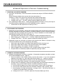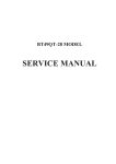
1
AUTOMATIC FILM PROCESSOR
SERVICE MANUAL
TABLE OF CONTENTS
Introduction . . . . . . . . . . . . . . . . . . . . . . . . . . . . . . . . . . . . . . . . . . . . . . . . . . . . . . .
Product Overview . . . . . . . . . . . . . . . . . . . . . . . . . . . . . . . . . . . . . . . . . . . . . . . . . .
Specifications . . . . . . . . . . . . . . . . . . . . . . . . . . . . . . . . . . . . . . . . . . . . . . . . . . . . . .
Plumbing Connections - Option 1 . . . . . . . . . . . . . . . . . . . . . . . . . . . . . . . . . . . .
Plumbing Connections - Option 2 . . . . . . . . . . . . . . . . . . . . . . . . . . . . . . . . . . . .
Plumbing Connections . . . . . . . . . . . . . . . . . . . . . . . . . . . . . . . . . . . . . . . . . . . . .
Water Recirculation Option . . . . . . . . . . . . . . . . . . . . . . . . . . . . . . . . . . . . . . . . . .
Major Assemblies and Parts . . . . . . . . . . . . . . . . . . . . . . . . . . . . . . . . . . . . . . . . . .
Internal Parts Identification . . . . . . . . . . . . . . . . . . . . . . . . . . . . . . . . . . . . . . . . . .
Operator Controls . . . . . . . . . . . . . . . . . . . . . . . . . . . . . . . . . . . . . . . . . . . . . . . . . .
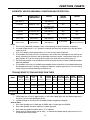
Function Charts . . . . . . . . . . . . . . . . . . . . . . . . . . . . . . . . . . . . . . . . . . . . . . . . . . . .
Measuring Replenisher Dispensing . . . . . . . . . . . . . . . . . . . . . . . . . . . . . . . . . . . .
Electrical Diagrams and Test Points . . . . . . . . . . . . . . . . . . . . . . . . . . . . . . . . . . .
Troubleshooting . . . . . . . . . . . . . . . . . . . . . . . . . . . . . . . . . . . . . . . . . . . . . . . . . . . .
Section 1 Operation and Function Troubleshooting . . . . . . . . . . . . . . . . . . . . . . . . .
Section 2 Film Quality Troubleshooting . . . . . . . . . . . . . . . . . . . . . . . . . . . . . . . . . .
Avoiding Chemistry Contamination . . . . . . . . . . . . . . . . . . . . . . . . . . . . . . . . . . .
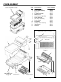
Cover Assembly . . . . . . . . . . . . . . . . . . . . . . . . . . . . . . . . . . . . . . . . . . . . . . . . . . . .
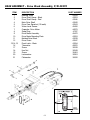
Base Assembly - Top View . . . . . . . . . . . . . . . . . . . . . . . . . . . . . . . . . . . . . . . . . . .
Base Assembly - Bottom View . . . . . . . . . . . . . . . . . . . . . . . . . . . . . . . . . . . . . . . .
Base Assembly - Drive Block Assembly, P/N 45270 . . . . . . . . . . . . . . . . . . . . .
Base Assembly - Solenoid, P/N 43980 . . . . . . . . . . . . . . . . . . . . . . . . . . . . . . . .
Base Assembly - Heater Pad, P/N 45950 . . . . . . . . . . . . . . . . . . . . . . . . . . . . . .
Base Assembly - Internal Water Recirculation . . . . . . . . . . . . . . . . . . . . . . . . . .
Roller Transports . . . . . . . . . . . . . . . . . . . . . . . . . . . . . . . . . . . . . . . . . . . . . . . . . . .
Roller Transport Parts . . . . . . . . . . . . . . . . . . . . . . . . . . . . . . . . . . . . . . . . . . . . . . .
Maintenance - Weekly . . . . . . . . . . . . . . . . . . . . . . . . . . . . . . . . . . . . . . . . . . . . . .
Maintenance - Monthly . . . . . . . . . . . . . . . . . . . . . . . . . . . . . . . . . . . . . . . . . . . . .
Maintenance - Quarterly . . . . . . . . . . . . . . . . . . . . . . . . . . . . . . . . . . . . . . . . . . . .
Daylight Loader . . . . . . . . . . . . . . . . . . . . . . . . . . . . . . . . . . . . . . . . . . . . . . . . . . . .
Spare Parts . . . . . . . . . . . . . . . . . . . . . . . . . . . . . . . . . . . . . . . . . . . . . . . . . . . . . . . .
2
3
4
5
6
7
8
9
10
11
12
13
18
19
23
23
29
37
38
40
42
44
45
46
48
49
50
52
53
55
57
58
INTRODUCTION
Purpose
This document provides the instructions necessary to perform repair and maintenance of the
AT2000 XR Automatic Film Processor. It is intended for all recognizable field servicing of the
unit and includes procedures to disassemble the unit to access internal components as well
as steps necessary to perform preventive maintenance, inspection, cleaning, troubleshooting
and removal/replacement of defective parts.
This manual is not intended for the routine use of the AT2000 XR Film Processor. Refer to
the Operator's Manual shipped with the product for all processor operation. It is further
understood that repair and maintenance information provided herein is to be performed by a
trained servicing technician.
Power Removal
Prior to performing the procedures contained in this document, turn off power switch by placing
the rocker switch on the top of the unit to the OFF (0) position. Also disconnect the line cord
from the wall outlet and the communication cable from the Scanner.
Warnings and Caution Statements
In these instructions, the following definitions Apply for all WARNINGS and CAUTION
Statements:
Warnings: Any operation, procedure or practice, which, if not strictly observed, may result in injury
or long term health hazards to personnel or patients.
Cautions:
Any operation, procedure or practice, which, if not strictly observed, may result in
destruction of equipment or loss of treatment effectiveness.
Task Guidelines
Personnel performing maintenance and repair tasks contained in this manual should follow
standard industry guidelines for working on electronic equipment as necessary. These
include the following:
K Always use a clean well-lit work area with ample space required for the size of the job.
K Always make sure to protect finished surfaces from scratches or other damage by
using cushioning material such as a soft cloth or packaging material between the
finished surfaces and the area that may cause damage.
K Keep all attaching hardware and fastening screws together with the associated
removed assembly. If necessary use separate storage containers or envelopes for
each hardware group.
K Prior to removing any part or assembly, note location and orientation of assemblies
being removed.
K Tag wires and associated mating connectors before disconnecting.
K Use care when disconnecting mating connectors so as not to damage the connector
keys and connection to the associated printed circuit board, wire or cable.
K Be aware of the damage impact of electrostatic discharge (ESD) on electronic devices
and use ESD precautions when handling printed circuit boards and wiring comprising
the Scanner.
3
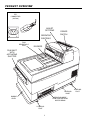
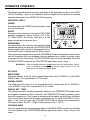
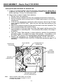
PRODUCT OVERVIEW
IEC
CONNECTOR
(At Rear)
ADJUST
SET-TEMP
POWER
SWITCH
OPERATOR
CONTROLS
FILM
RECEPTACLE
TRAY
DIVIDERS
FILM INLET
WITH
ACTIVATING
SHUTTER
LEVELING
BASE
BUBBLE
LEVEL
REPLENISHMENT
PUMP AND AGITATOR
MOTOR DRAW
LEVELING
FOOT
4
LEVELING
FOOT
SPECIFICATIONS
ELECTRICAL
115VAC, 60 Hz, 8 AMPS. Use a 15 AMP, 3 prong, grounded outlet. A separate dedicated 15 AMP line is recommended.
WATER FLOW
1/2 gallon per minute water flow (while processing film).
WATER PRESSURE
80 PSI maximum / 30 PSI minimum. Water source must have a
manual shut-off near processor.
WATER CONNECTION
Valved 3/4" male garden hose fitting near rear of processor. 6'
hose with standard female garden hose fittings provided.
WATER BACKFLOW
PREVENTION
A vacuum breaker is not normally required because the processor has a 1" air gap between water supply inlet and the maximum
possible water level height.
WATER TEMP
55° F (13° C) to 80° F (27° C)
DRAIN
1-1/2" vertical PVC standpipe, open at top. DO NOT DRAIN INTO
COPPER OR BRASS. The top of the standpipe must be 6" below
the bottom of the countertop.
DIMENSIONS
18" (H) x 15" (W) x 25" (D) with leveling base.
WEIGHT
90 lbs. with water and chemistry (75 lbs. empty).
VENTILATION
Room air temperature must be below 80° F (27° C), during processing. Because heat is generated during processing, adequate
ventilation is required to maintain darkroom temperature. 8 - 12
volume room air changes per hour.
Depth 25"
22"
Height 16"
4" Minimum Clearance
2"
15"
Width
2"
23 1/2"
DIMENSIOND
5
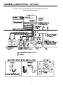
PLUMBING CONNECTIONS - OPTION 1
Chemistry recovery and wash water sewer disposal connection.
(If permitted by local code.)
6
PLUMBING CONNECTIONS - OPTION 2
Chemistry recovery and wash water sewer disposal connection.
(If permitted by local code.)
7
PLUMBING CONNECTIONS
CONNECT TO PLUMBING
(See Plumbing Connections - OPTIONS 1 & 2)
K Match color-coded drain hoses to corresponding color-coded label on barbed fittings
at the rear of the unit. Mount the hose end onto the barbed fitting by rotating the hose
clockwise while pushing. Push the hose flush up against the barbed fitting, leaving no
space. If removal of the hose is necessary, rotate clockwise while pulling the hose. No
clamps are required as the hose is self clamping.
K If routing the drain lines, replenishment lines and water inlet hose through the countertop, drill a 2-1/2" diameter hole through the countertop (See Plumbing Connection
illustrations). For routing replenishment lines through the counter, unscrew the retaining nut under cap to remove the cap assembly. Cut the replenishment lines to appropriate length.
OPTION 1:
Route water (white) drain hose to a vertical 1-1/2" PVC standpipe. Route
Developer (black) and Fixer (red) drain hoses to chemistry recovery containers under the counter.
OPTION 2:
Route all three drain hoses into a vertical 1-1/2" PVC standpipe.
NOTE: Hoses must always slope downward to drain pipe or recovery containers without any "U's"
or upward bends in the hose.
Hoses routed into the drain pipe must be cut so that the ends are at a min. 6" above the
standing water in the P-trap at the bottom of the pipe.
Hoses routed into the chemistry recovery containers must be cut so that the ends are 2"
above the highest expected solution level in the recovery container.
K Chemistry recovery & replenishment bottles must be placed below the processor or
under the counter.
REPLENISHER BOTTLES CANNOT BE ABOVE THE PROCESSOR.
8
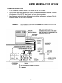
WATER RECIRCULATION OPTION
PLUMBING CONNECTIONS
1. Fill the container with fresh water to the bottom of the WATER label.
2. Cut the wash water drain hose so that when it is inserted into the water container it reaches
to the bottom of the WATER label. Insert the hose into the container.
3. Insert the wash water inlet hose all the way to the bottom of the water container. See the
illustration below for the correct installation.
WARNING:
THIS PLUMBING CONFIGURATION CANNOT BE CONNECTED TO A FRESH
WATER SUPPLY LINE.
9
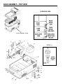
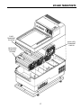
MAJOR ASSEMBLIES AND PARTS
ITEM
1
2
3
4
5
6
7
DESCRIPTION
PART NUMBER
Cover Assembly with Electronic Module
Base Assembly
Developer Transport
Fixer Transport
Wash/ Dry Transport
Leveling Base Assembly
Leveling Feet
10
45800
45200
45500
45505
45510
45100
43106
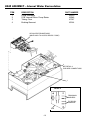
INTERNAL PARTS IDENTIFICATION
PROCESSOR
COVER
ELECTRICAL
CABLE
PROCESSOR
COVER
P/N 45800
RAISED BOSS
BAFFLE PLATES
INNER BAFFLE
P/N 41307
ON LEFT END BOTTOM OF
BAFFLE MUST PASS BELOW
RAISED BOSS ON SIDE PLATE
ACTIVATING
SHUTTER
WASH/DRY RACK
P/N 45510
FIXER RACK
(RED)
P/N 45505
OUTER BAFFLE
P/N 43526
DEVELOPER
RACK (BLACK)
P/N 45500
WEEP HOLE
DEVELOPER
DRAIN TUBE
(BLACK)
P/N 43286
FIXER DRAIN
TUBE (RED)
P/N 43287
RUBBER
WASHER
P/N 43271
WASH/DRY
DRAIN TUBE
P/N 43270
DRIVE BLOCK ASS’Y
P/N 45240
FILL LINE
WATER
LEVEL
SENSOR
P/N 45450
DEVELOPER
TANK
FIXER
TANK
GEAR COVER
P/N 43258
WORM
DRIVESHAFT
P/N 43242
WASH
TANK
DEVELOPER
RACK LATCH
P/N43254
FILM
INLET
P/N 45567
BUBBLE
LEVEL
LEVELING
FEET
P/N 43106
LEVELING
BASE
P/N 45100
FIXER RACK
LATCH
P/N 43255
THERMISTOR PROBE P/N 45790
SAFETY SWITCH ACTIVATOR P/N 45323
11
WASH/DRY
RACK
LATCHES
P/N 43256
OPERATOR CONTROLS
The following provides a brief summary description of the operating controls of the AT2000
XR Film Processor. Refer to the Operator's Manual shipped with the product for detailed
operation informaion for the AT2000 XR Film Processor.
INDICATOR LIGHTS
POWER
Illuminates when the POWER switch (located on top)
is in the ON position.
READY
Illuminates when chemistry has reached SET-TEMP
operating temperature (factory Pre-set at 82° F (28°
C). When READY illuminates, chemistry is at the
proper temperature to process films.
PROCESSING
Illuminates when a film has been inserted and is being
transported through the process cycle.PROCESSING
flashes regularly when the film is feeding past the film
inlet shutter and for 5 seconds after the shutter closes.
When processing extraoral films, wait until PROCESSING stops flashing before inserting the
next film to prevent films from overlaping. When the processor is in a stand - by mode, ready
to accept films for processing, the PROCESSING light will not be illuminated. When the
CLEANING MODE is selected, the PROCESSING light flashes (short - long...)
IMPORTANT:
ENDO is intended to process a single periapical size film, and by default, if another film is attempted to process after the shutter closes from the 1st film, the
process cycle will change to NORMAL Mode.
KEY PADS
ENDO SPEED
The arrow indicator to the left of the keypad flashes when the A/T 2000XR is in the ENDO
SPEED mode. Film is processed in 2-1/2 minutes.
NORMAL SPEED
The arrow indicator to the left of the keypad illuminates steady when the A/T 2000XR is
in the NORMAL mode. Film is processed in 5-1/2 minutes.
DISPLAY SET - TEMP
The selected chemistry set point temperature flashes on the TEMPERATURE display when
the keypad is pressed and held. Otherwise, the TEMPERATURE display indicates actual
chemistry temperature. If the keypad is pressed and the display does not flash a different
value, the set point and actual chemistry temperatures are the same and READY is illuminated. If this is not the case, see TROUBLE SHOOTING or contact your authorized Air
Techniques Dealer. The SET - TEMP is factory pre-set at 82° F (28° C).
CLEANING MODE
Use this keypad only during cleaning procedures. CLEANING MODE activates an extended
10 minute process cycle. PROCESSING indicator light flashes (short - long...) when in this
mode.
12
FUNCTION CHARTS
AT2000 XR FUNCTION & OPERATION CHARTS
The AT2000 XR Film Processor's function and status conditions, as designed, are separated
into six categories listed below. The charts associated will provide insite to required processor
operation and expedite any trouble-shooting, if applicable. Refer to the appropriate Function
Chart, as required, to quickly identify and resolve the issue at hand.
K FILM SHUTTER FUNCTIONS . . . . . . . . . . . . . . . . . . . . . . . . . . . . . . . . . . . . .13
K FUNCTIONAL MODES . . . . . . . . . . . . . . . . . . . . . . . . . . . . . . . . . . . . . . . . . . .14
K CHEMISTRY HEATER ABNORMAL CONDITIONS AND PROTECTION . . . .15
K TRAILING-EDGE TO TRAILING-EDGE FILM TIMES . . . . . . . . . . . . . . . . . . .15
K HEATER PAD POWER CONTROL . . . . . . . . . . . . . . . . . . . . . . . . . . . . . . . . .16
K REPLENISHER RATES FOR DEVELOPER AND FIXER . . . . . . . . . . . . . . . .17
K MEASURING REPLENISHER DISPENSING . . . . . . . . . . . . . . . . . . . . . . . . .18
FILM SHUTTER FUNCTIONS
PROCESSING STATE
SHUTTER STATE
MODE (Speed) CHANGE
or RESULT
Stand By
CLOSED
NORMAL to ENDO to NORMAL
Stand By
CLOSED,
then OPEN for
4 seconds or more
Process starts, then stops at shutter closed and
stays in selected mode.
Stand By
CLOSED,
then OPEN for
4 seconds or more
Process starts, and continues to operate in
selected mode.
Operating
OPEN
NORMAL to ENDO to NORMAL
Operating
CLOSED
ENDO to NORMAL only
Operating ENDO
Cycle
CLOSED,
then OPEN for
4 seconds or more
ENDO will default to NORMAL then starts a
new cycle.
Operating Normal Cycle
CLOSED,
then OPEN for
4 seconds or more
Remains in NORMAL mode, and starts a new
cycle.
Cleaning (Manual)
CLOSED or OPEN
NORMAL mode only.
Inhibits intial replenishment.
Shutter Action:
1. Accumunlates film length for replenishment.
2. Does not initiate process cycle.
End of ENDO Cycle
CLOSED
Restes to NORMAL mode
End of Normal Cycle
CLOSED
Stays in NORMAL mode
Power On
CLOSED or OPEN
Is in NORMAL mode
Power On
OPEN
Inhibits intial replenishment
13
FUNCTION CHARTS
FUNCTIONAL MODES
READY NORM
ENDO
LIGHT ARROW ARROW
PROC
LIGHT
REPLEN
PUMP
DEV TEMP
DISPLAY
Turn ON
> -15° F
Developer
Temperature
Heatup
OFF
ON
OFF
OFF
Closed
100%
OFF
Turn ON
< 77° F
Developer
Temperature
Heatup
OFF
ON
OFF
OFF
Closed
100%
OFF
Turn ON
< 77° F
Developer
Temperature
Heatup
OFF
or
ON
ON
OFF
OFF
Closed
100% (1st min)
<100% (to OFF)
OFF
Normal
Temperature
Rise
77 to 81° F
Developer
Temperature
Heatup
OFF
ON
OFF
OFF
Closed
90 to 20%
OFF
OFF
Fast
Temperature
Rise
77 to 81° F
Developer
Temperature
Heatup
OFF
ON
OFF
OFF
Closed
45 to 10%
OFF
OFF
At Set Point
82° F
82° F
ON
ON
OFF
OFF
Closed
OFF
OFF
OFF
OFF
OFF
OFF
In Control Loop
81 to 84° F
(Guard Band)
80 to 83° F
SEE NOTE 1
82° F
(ADC=118
(ADC=118)
ON
ON
OFF
OFF
SHUTTER HEATER POWER
DRYER
&
RECIRC
MODE
Closed
SEE NOTE 2
Developer Hot
> 83° F
Processing
NORMAL
80 to 84° F
Developer
Temperature
84° F
(Set Point)
OFF to 20% &
100% for 1 min
every ADC change
if temp drops.
ON
(90 sec)
ON
(90 sec)
ON
(90 sec)
SEE NOTE 3
OFF
ON
OFF
OFF
Closed
OFF
OFF
ON
ON
OFF
Flashing
Open
(+5 sec)
Off to 20%
ON
ON as long
as shutter
is open
SEE NOTE 4
Processing
NORMAL
80 to 84° F
84° F
(Set Point)
ON
ON
OFF
ON
Closed
Off to 20%
ON
ON as long
as shutter
is open
SEE NOTE 4
Processing
ENDO
80 to 84° F
84° F
(Set Point)
ON
ON
OFF
Flashing
Open
(+5 sec)
Off to 20%
ON
ON as long
as shutter
is open
SEE NOTE 4
Processing
ENDO
80 to 84° F
84° F
(Set Point)
ON
ON
OFF
ON
Closed
Off to 20%
ON
ON as long
as shutter
is open
SEE NOTE 4
Processing
CLEANING
80 to 84° F
Processing
CLEANING
80 to 84° F
Processing
CLEANING
(shutter open fail)
80 to 84° F
84° F
(Set Point)
84° F
(Set Point)
84° F
(Set Point)
ON
ON
OFF
ON
ON
OFF
ON
ON
OFF
Flashing
(short/long)
Flashing
(short/long)
Closed
Off to 20%
ON
OFF
Open
Off to 20%
ON
OFF
Off to 20%
ON
OFF
Open, but
no signal =
(short/long)
Closed
Flashing
Notes:
1. Control loop 80 to 84°F during heat up and from above 84°F upon cool down.
2. Set point temperature range is between 79 and 86°F (ADC = Analog to Digital Count).
3. 100% HEATER POWER for 1 minute when processor power is turn ON each time the ADC changes
(increases) as temperature drops and every 4 minutes if temperature is below set point and ADC does
not change.
4. See page 17 for pump on times.
14
FUNCTION CHARTS
CHEMISTRY HEATER ABNORMAL CONDITIONS AND PROTECTION
DEVICE
DEVICE STATE or
TEMPERATURE
DISPLAY
HEATER
CONTROL
HEATER
Thermistor
(SEE NOTE 1)
OPEN
-15°F
(SEE NOTE 2)
OFF
OFF
Thermistor
SHORT or > 99°F
99°F
OFF
OFF
Thermistor
< -15°F
OFF
OFF
Thermistor
Set Point to 99°F
OFF
OFF
Thermistor
> 99 to 130°F
99°F
OFF
OFF
Plate Thermal Switches
(Dev or Fix)
Plate Thermal Fuse
(Plate Center)
> 130°F
(SEE NOTE 4)
>305°F
(SEE NOTE 6)
Thermistor Condition
(SEE NOTE 5)
Thermistor Condition
(SEE NOTE 5)
Developer Temp
(SEE NOTE 3)
Thermistor Condition
(SEE NOTE 5)
By Thermistor
By Thermistor
OFF
(Resetable)
OFF
(Blown Thermal Fuse)
Notes:
1. There is only a developer thermistor, There is no monitoring or control of the fixer temperature.
2. A sensed temperature of <-15°F produces a voltage that looks like an open circuit and the heater
control turns off.
3. At 32°F the display shows approximately 37°F due to zener diode conduction.
4. This condition occurs only if there is no chemistry in one or both of the developer or fixer tanks for the
tank(s) containing no chemistry and the developer thermistor senses a temperature below the set
point (typically 82°F) for the heating control system has failed into being continuously on.
5. The thermistor condition is the temperature that the thermistor senses or to which it defaults based on
abnormal conditions.
6. This condition occurs only if there both tanks and both thermal switches fail in the closed position and
the developer thermistor is sensing a temperature below the set point (typically 82°F) or the heating
control system has failed into being continuously on.
TRAILING EDGE TO TRAILING EDGE FILM TIMES
SHUTTER
to DEV
IN
DEV
X-OVER to
FIX
IN
FIX
X-OVER
to WASH
(min:sec)
(min:sec)
(min:sec)
(min:sec)
(min:sec)
(min:sec)
(min:sec)
(min:sec)
(min:sec)
(min:sec)
NORMAL
0:19
0:37
0:37
0:37
0:40
0:37
0:20
01:39
01:00
05:30
ENDO
0:08
0:16
0:18
0:28
0:17
0:16
0:09
0:33
0:33
02:33
ENDO (Cul)
0:08
0:16
0:17
0:16
0:17
0:16
0:09
0:33
0:46
02:20
CLEANING
0:19
0:37
0:37
0:37
0:40
0:37
0:20
01:39
04:30
05:30
MODE
(SEE NOTE 2)
(SEE NOTE 1) (SEE NOTE 1)
IN
X-OVER
IN
OVERTOTAL
WASH to DRYER DRYER RUN TIME PROCESS
Notes:
1. Trailing edge not in fixer by approximately 1/4 inch when speed goes slow and leading edge out of
fixer by a 1/16 inch when speed goes to fast.
2. CLEANING Mode is formally known as MANUAL Mode (Keypad has changed).
General Notes:
1. Drive motor gearbox has 21-tooth gear for ENDO and a 52-tooth gear for NORMAL.
2. Drive motor gearbox and worm shaft have 12-tooth sprockets.
3. Drive motor has grade A insulation and a 1.8 uF capacitor.
4. Shutter close to speed change (fast to slow) = 41 seconds and speed change (slow to fast) is 23 or
64 seconds after shutter closes.
15
FUNCTION CHARTS
HEATER PAD POWER CONTROL
General Note:
The theroetical heating rate of the chemistry is approximately 0.7°F/min (-1°F/min).
The actual heating of chemistry may be different due to thermal inertia.
DEVELOPER
TEMPERATURE
(A/D Count)
HEATER POWER PERCENTAGE
For Heating rate
(SEE NOTE 1)
NEON TEST LAMP
Placed Across
Leads of Heater
< 0.44°F/min.
> 0.44°F/min.
84 (114)
0
0
LAMP OFF
84 (115)
0
0
LAMP OFF
83 (116)
0
0
LAMP OFF
83 (117)
0
0
LAMP OFF
0
0
LAMP OFF
82 (118)
(SEE NOTE 2)
82 (119)
81 (120)
80 (121)
80 (122)
79 (123)
79 (124)
78 (125)
78 (126)
77 (127)
20
10
(SEE NOTE 4)
20
(SEE NOTE 4)
30
(SEE NOTE 4)
40
(SEE NOTE 4)
50
(SEE NOTE 4)
60
(SEE NOTE 4)
70
(SEE NOTE 4)
80
(SEE NOTE 4)
90
(SEE NOTE 4)
LAMP FLASHES
(SEE NOTE 3)
10
LAMP FLASHES
15
LAMP FLASHES
20
LAMP FLASHES
25
LAMP FLASHES
30
LAMP FLASHES
10
LAMP FLASHES
15
LAMP FLASHES
20
LAMP FLASHES
77 (128)
100
25
LAMP ON STEADY
76 to 32
100
30
LAMP ON STEADY
Notes:
1. 0.44°F/min = 1°F/min is a selected reduced power control condition to prevent temperature overshoot.
2. Set point = 82°F (A/D count) = 118 = 1 Volt.
3. ON flash duration is proportionate to the HEATING POWER percentage.
4. 100% HEATER POWER for 1 minute when processor power is turn ON each time the ADC changes
(increases) as temperature drops and every 4 minutes if temperature is below set point and ADC does
not change.
16
FUNCTION CHARTS
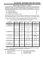
REPLENISHER RATES FOR DEVELOPER AND FIXER
STANDARD (DOMESTIC) AT2000 XR FILM PROCESSOR
FILM
LENGTH
SHUTTER
Open Time
PUMP
On Time
POWER Turn ON
0 inch
0 min 0 sec
90 sec
126
4.26
POWER Turn ON - CLEANING Mode
0 inch
0 min 0 sec
0 sec
0
0
SHUTTER OPEN - NORMAL Mode
15 inch
2 min 15 sec
35 sec
49
1.66
SHUTTER OPEN - ENDO Mode
32 inch
2 min 15 sec
35 sec
49
1.66
SHUTTER OPEN - CLEANING Mode
15 inch
2 min 15 sec
35 sec
49
1.66
MODE
(SEE NOTE 1)
(SEE NOTE 1)
FLUID VOLUME
(oz)
(ml)
CANADIAN (CUL) AT2000 XR FILM PROCESSOR
FILM
LENGTH
SHUTTER
Open Time
PUMP
On Time
POWER Turn ON
0 inch
0 min 0 sec
0 sec
126
4.26
POWER Turn ON - CLEANING Mode
0 inch
0 min 0 sec
0 sec
0
0
SHUTTER OPEN - NORMAL Mode
15 inch
2 min 15 sec
35 sec
49
1.66
SHUTTER OPEN - ENDO Mode
32 inch
2 min 15 sec
35 sec
49
1.66
SHUTTER OPEN - CLEANING Mode
15 inch
2 min 15 sec
35 sec
49
1.66
MODE
(SEE NOTE 1)
(SEE NOTE 1)
FLUID VOLUME
(oz)
(ml)
Notes:
1. CLEANING Mode is formally known as MANUAL Mode (Keypad has changed).
General Notes:
1. There is no replenishment in CLEANING Mode, but standard replenishment occurs if the shutter is
opened for the prescribed times
2. Algorithm for replenisher turn-on time is:
Replenisher start time = NORMAL shutter OPEN time + 2 X ENDO shutter OPEN time.
17
MEASURING REPLENISHER DISPENSING
The following provides an approach to verifying the replenisher pump output flow rate for
developer and fixer chemistry. This technique will aid in solving replenisher related problems.
Equipment needed: 250ml Graduated Beaker and Stopwatch
Initial Procedure
1. Verify the electronics are operating as required before starting a replenishment rate
examination. Upon powering up the processor an initial replenishment of chemistry lasts
90 seconds, this can be confirmed by listening for the pump sound near the circulator
drawer (will be the only sound heard from the processor).
2. Ready the stopwatch, turn the power switch ON and start the stopwatch together. Allow
the initial replenishment (pumping) of chemistry to be completed. The replenishers must
pump for a time period between 88 and 92 seconds, discontinued this test procedure if it
is not within that range.
3. Turn the unit's power switch OFF and unplug the processor from the outlet.
Important:
Avoid spillage or cross contamination of chemistry.
4. Gain access to the processor chemistry drain lines; each will have to be removed from
respective drain catches to perform this procedure, and then reinstalled upon completion.
5. Confirm that there is an adequate amount of replenishment chemistry in the replenishment
containers (bottles), and that the processor chemistry level is at or near the overflow tube
weir level before proceeding. If any of the levels are low, fill to required levels.
Check Developer Pumping rate
1. Remove the developer (black) drain hose from is drain catch and position it where the
sample to be measured can be collected with the beaker. Be sure that the drain hose
does not have any uphill bends in it, the hose should be on a continuous downward slope
or at worst lying horizontally flat between the processor and the open drain hose end.
2. Plug the processor line cord into the outlet and position the open end of the drain hose
into the 250ml beaker.
3. Turn the power switch ON and wait for the initial replenishment (pumping) of chemistry to
be completed. This takes 90 seconds. This ensures that the liquid in the processor is at
its high and overflow level, and the liquid in the drain line has been primed. Turn power
switch OFF, discard the chemistry in the beaker, and prepare to sample the replenishment
rate with the stopwatch.
4. Position the end of the drain hose into the 250ml beaker, ready the stopwatch, turn the
power switch ON and start the stopwatch together.
5. At the end of the initial replenishment cycle (90 seconds) turn power switch OFF and view
the liquid volume in the beaker. The replenished volume must be between 120ml to
130ml.
6. Reinstall the developer drain hose in its catch.
Check Fixer Pumping rate
1. Repeat the developer replenishment procedure, except use the fixer (red) drain hose.
2. The replenished volume must be between 120ml and 130ml.
DONE
18
ELECTRICAL DIAGRAMS AND TEST POINTS
AT2000 XR Electrical Diagrams & Test Points
Wiring, test point and thermistor resistance information for the AT2000 XR Film Processor is
provided in this section. The associated charts/diagrams identify all serviceable features and
provide the required parameters to facilitate equipment troubleshooting. Refer to the
appropriate information as required to quickly identify and resolve the equipment fault issue.
K TEST POINT CHART . . . . . . . . . . . . . . . . . . . . . . . . . . . . . . . . . . . . . . . . . . . .19
K SYSTEM SCHEMATIC . . . . . . . . . . . . . . . . . . . . . . . . . . . . . . . . . . . . . . . . . . .20
K CONNECTOR DIAGRAMS . . . . . . . . . . . . . . . . . . . . . . . . . . . . . . . . . . . . . . .21
K THERMISTOR RESISTANCE CHART . . . . . . . . . . . . . . . . . . . . . . . . . . . . . . .22
The following test point chart lists the test point and expected voltage and resistance value
for the associated component of the AT 2000 XR Film Processor. Use the tables along
with the system schematic to check the operating values of each listed component.
Note:
All values listed are the normal operating parameters for that component. Any different
values measured during testing implies a problem with that component.
COMPONENT
(Being Evaluated)
TESTPOINT
CONNECTOR
TESTPOINT
PIN No's
J1
4 & 12
2&3
N/A
N/A
500 - 600
500 - 600
J1
3 & 5 (Endo)
103.5 - 126.5
245 - 300
J1
3 & 6 (Endo)
103.5 - 126.5
245 - 300
1&2
N/A
500 - 600
WATER SENSOR (Shorted
Contacts)
J2
(component side)
DRIVE MOTOR
J3
(component side)
VOLTGAGE RANGE RESISTANCE RANGE
(VAC)
(Ohms)
J3
(harness side)
1 & 3 (Endo)
165 - 175
245 - 300
J3
(harness side)
2 & 3 (Norm)
165 - 175
245 - 300
3 & 10
N/A
52.5 - 60.5
1&2
103.5 - 126.5
N/A
HEATER PAD
J1
J4
J4
(harness side)
1&2
N/A
52.5 - 60.5
13 & 14
N/A
1&3
N/A
See
Resistance Chart,
page 22
2&3
103.5 - 126.5
1225 - 1500
1&2
103.5 - 126.5
N/A
J9
1&2
103.5 - 126.5
1225 - 1500
J1
3&9
103.5 - 126.5
505 - 615
WATER RECIRCULATION
PUMP
J1
3&9
103.5 - 126.5
92 - 140
RECIRCULATORS
J1
3&8
103.5 - 126.5
11 - 13
TB4
1&2
103.5 - 126.5
N/A
(component side)
THERMISTOR
J1
J5
(component side)
REPLENISHERS
J1
J9
WATER SOLENOID
(harness side)
OR
Note:
All J1 measurements are made relative to base harness, inside processor while module
is connected. Use needle nose probes when for measurements.
COMPONENT CONNECTOR LIST
J1 = MODULE CONNECTOR (14 PIN ROUND CONNECTOR ON REAR OF PROCESSOR)
J2 = WATER LEVEL SENSOR
J5 = DEVELOPER THERMISTOR PROBE
J3 = DRIVE MOTOR
J9 = REPLENISHER PUMPS
J4 = CHEMISTRY HEATER PAD
TB4 = CIRCULATOR DRAWER
19
SYSTEM SCHEMATIC
20
CONNECTOR DIAGRAMS
CONNECTOR COMPARTMENT
COVER.
REMOVE TO ACCESS
J2, J3, J4, J5
TAKE J1 MEASUREMENTS
HERE TO TEST COMPONENT
VOLTGAGE / RESISTANCE PER
TEST POINT CHART.
J5
THERMISTOR
WATER SENSOR
J4
HEATER PAD
J3
DRIVE MOTOR
21
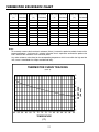
THERMISTOR RESISTANCE CHART
Bath Temp Thermistor
(°F)
Resistance
Bath Temp Thermistor
(°F)
Resistance
Bath Temp Thermistor
(°F)
Resistance
Bath Temp Thermistor
(°F)
Resistance
60
7658
70
5941
80
4651
90
3668
61
7642
71
5797
81
4540
91
3583
62
7274
72
5655
82
4432
92
3501
63
7089
73
5516
83
4328
93
3420
64
6911
74
5382
84
4225
94
3343
65
6739
75
5251
85
4126
95
3266
66
6569
76
5125
86
4029
96
3193
67
6406
77
5000
87
3936
97
3120
68
6245
78
4882
88
3844
98
3050
69
6092
79
4765
89
3755
99
2982
Notes:
To accurately measure the thermistor’s resistance (Ohms), immerse the probe into a bath of water with a
known temperature. A minimum of 2 minutes immersion time is required to acclimate the probe to the
bath. Measure the resistance at the connector points.
Any other resistance value found at the corresponding temperature which is not within the high and low
limit curves is considered Out of Spec and deemed faulty.
THERMISTOR CURVE TRACKING
(± 0.9° F)
9
8
6
5
4
3
2
1
0
60 62 64 66 68 70 72 74 76 78 80 82 84 86 88 90
TEMPERATURE
(°F)
22
RESISTANCE
(K ohms)
7
TROUBLESHOOTING
AT2000 XR troubleshooting guide is provided in two categories for quick access to problems
that are specifically electro-mechanical in nature, and problems specifically relating to film
quality. Other equipment faults can also be resolved using the troubleshooting section
provided in the processor User’s Manual.
Section 1: Intended for the diagnosis and/or repair of faults relating to electro-mechanical
operation/function for the AT2000 XR Film Processor. The itemized list below is
a summary of those issues considered, for the complete diagnosis and/or repair
of the issue exhibiting refer to the subsequent pages as identified.
Section 2: Intended for the diagnosis and/or corrective actions of film quality, component
staining, and chemistry issues. Refer to page 29 for a summary of section 2
filim troubleshooting.
SECTION 1. AT2000 XR Operation & Function Troubleshooting
Diagnosis of Electro-Mechanical Components
Note:
To assure proper diagnosis and servicing of the AT2000XR, it is strongly recommended that
the use of all charts and diagrams provided in this manual accompany the service performed
as required.
1.
PROCESSOR IS TOTALLY INACTIVE . . . . . . . . . . . . . . . . . . . . . . . . . . . . . . . .24
N No Lights or activity with power switch ON
2.
PROCESS CYCLE WILL NOT START . . . . . . . . . . . . . . . . . . . . . . . . . . . . . . . .24
N Film shutter not activating when inserting a film - No Drive, Dryer, Etc..
3.
PROCESSOR DOES NOT STOP . . . . . . . . . . . . . . . . . . . . . . . . . . . . . . . . . . . .24
N Process cycle continues indefinitely
4.
PROCESSOR STOPS MID-CYCLE . . . . . . . . . . . . . . . . . . . . . . . . . . . . . . . . . .25
N Process cycle stops before film exits
5.
DRIVE MOTOR NORMAL SPEED DOES NOT RUN . . . . . . . . . . . . . . . . . . . . .25
N Motor does not function in NORMAL speed mode
6.
DRIVE MOTOR ENDO SPEED DOES NOT RUN . . . . . . . . . . . . . . . . . . . . . . .25
N Motor does not function in ENDO speed mode
7.
DRYER FAN / AIR HEATER PROBLEMS . . . . . . . . . . . . . . . . . . . . . . . . . . . . . .26
N Fan motor not working or blows cool air
8.
REPLENISHER PUMP PROBLEMS . . . . . . . . . . . . . . . . . . . . . . . . . . . . . . . . . .26
N Replenisher not operating, not suctioning, using too much chemistry
9.
CHEMISTRY AGITATOR PROBLEMS . . . . . . . . . . . . . . . . . . . . . . . . . . . . . . . . .26
N Agitators not spinning (clogged / motors not running)
10. CHEMISTRY TEMPERATURE CONTROL PROBLEMS . . . . . . . . . . . . . . . . . . .27
N Chemistry not at 82° and/or display reads error code
11. KNOCKING / THUMPING NOISES DURING PROCESS CYCLE . . . . . . . . . . .27
N Transport and/or drive train is jammed or out of adjustment
12. WASH WATER PROBLEMS . . . . . . . . . . . . . . . . . . . . . . . . . . . . . . . . . . . . . . . .28
N Water solenoid does not turn ON, or OFF, or intermittent ON & OFF
23
TROUBLESHOOTING
AT 2 0 0 0 X R O p e r a t i o n & F u n c t i o n Tr o u b l e s h o o t i n g
1. PROCESSOR IS TOTALLY INACTIVE ( No Lights )
A. Check that the power switch is turned ON.
B. Check that the line cord is connected @ both the Base & wall outlet.
C. Check that the Electronics Module cable @ connector J1 is properly attached.
D. Check the fuse; If blown, replace with 8A / 250V 5mm Slow-Blow type (p/n 41914).
E. Check for loose connections and/or wires in Base, and using the TEST POINT CHART on page 19;
1. Check the voltage at connector J1, pins 1 & 3, on the Base – If the voltage is between 103.5 and
126.5VAC, replace Electronics Module (p/n 45415).
2. If no voltage is detected, check the output side of the IEC/RFI filter for voltage. Unplug the line
cord from the processor, remove the two fastening screws, and slide out the IEC/RFI filter. Plug line
cord back into the filter and check for voltage across the black (hot) and white (neutral) leads;
a. If the measured voltage is between 103.5 and 126.5VAC, unplug line cord and check for
continuity between black (hot) on filter & pin 1 @ J1, and continuity between white (neutral)
on filter and pin 3 at J1.
b. If the measured voltage is NOT between 103.5 and 126.5VAC, replace IEC/RFI filter (p/n 45975)
2. PROCESS CYCLE WILL NOT START (When inserting a film into film inlet - No drive, dryer, etc...)
A. Check that the Top Cover assembly is seated squarely on the Base – If not, the interlock switch may
not be engaged which will prevent the transport drive motor from running.
B. Check the Film Shutter assembly freely pivots and is not jammed – Remove Cover Tray for service;
1. If difficult to pivot, clean shutter hinges with a moist sponge and thoroughly dry.
2. If jammed or abnormally bent, try to re-shape the shutter flag and align as depicted by DETAIL “B”
and DETAIL “C” in the COVER ASSEMBLY section (page 46). With shutter in closed position, the
flag must be fully inserted into the PCB optic sensor. With shutter in open position, the flag must
be fully out of the PCB optic sensor. If Film Shutter is uncorrectable, replace the component (p/n
43584)
C. Check electronics function and using the SYSTEM SCHEMATIC – Remove Electronics Module from
top cover but leave connected @ J1. Disconnect J8 (green, blue, yellow wires) & depress the CLEANING
CYCLE button on keypad;
1. If difficult to pivot, clean shutter hinges with a moist sponge and thoroughly dry.
2. If processor DOES NOT start, replace Electronics Module (p/n 45415)
3. PROCESS CYCLE WILL NOT STOP (Process cycle continues indefinitely)
A. Check the Film Shutter assembly is not stuck on the Developer Transport rack entry roller, if so;
1. Inspect transport for squareness
2. If Shutter Guard is bent and contacts the transport, restore as required to eliminate contact.
B. Check the Film Shutter assembly freely pivots and is not jammed – Remove Cover Tray for service;
1. If difficult to pivot, clean shutter hinges with a moist sponge and thoroughly dry.
2. If jammed or abnormally bent, try to re-shape the shutter flag and align as depicted by DETAIL “B” and
DETAIL “C” in the COVER ASSEMBLY section (page 46). With shutter in closed position, the flag
must be fully inserted into the PCB optic sensor.With shutter in open position, the flag must be
fully out of the PCB optic sensor.
3. If Film Shutter is uncorrectable, replace the component (p/n 43584)
C. Check the PROCESS LED; If it's flashing, refer to troubleshooting item 2C above.
24
TROUBLESHOOTING
AT 2 0 0 0 X R O p e r a t i o n & F u n c t i o n Tr o u b l e s h o o t i n g
4. PROCESSOR STOPS IN MID-CYCLE (Stops before film exits the dryer)
A. Check for a low voltage condition due to another large motor (i.e.; refrigerator, compressor) on the
same circuit – If the other motor starts during a process cycle, it can draw too much voltage and interrupt the
cycle causing the AT2000XR to reset to stand-by.
If on a shared circuit, relocate to another circuit / dedicated circuit to eliminate problem.
B. Check for a temporary power outage – End results will be same as in item A
C. Check all the transport racks for squareness and inspect the gears for any broken parts;
1. If NOT square, place on level surface and loosen the tie rod screws but don’t remove. Firmly hold
down the rack plates so they sit flat against the surface and retighten the screws.
2. If any gears are broken, replace the appropriate gear if feasible or the affected transport.
D. Check the cleanliness of the transport racks – Failure to maintain the processor per the requirements
can cause the transport rollers to become “slimy” and allow the films to slip during processing.
If at all questionable, clean the transports and reiterate that the AT2000XR requires routine maintenance, which is fully described in detail in the USER’S MANUAL.
E. Reiterate if films are not fed straight when inserting into film inlet, they can get caught in the transports.
NOTE: Pedo films must be processed lengthwise
F.
Check the process time for both speeds – Hold Film Shutter open for 5 seconds then release;
1. If ENDO speed processing time after releasing the shutter is LESS THAN 2 min 40 sec, replace
Electronics Module (p/n 45415)
2. IF NORMAL speed processing time after releasing the shutter is LESS THAN 5 min 55 sec, replace
Module (p/n 45415)
5. DRIVE MOTOR “NORMAL” SPEED DOES NOT RUN
A. Check that the Top Cover assembly is seated squarely on the Base – If not, the interlock switch may
not be engaged which will prevent the transport drive motor from running.
B. Check all the transport racks gears for any broken parts;
If any gears are broken, replace the appropriate gear if feasible or the affected transport.
C. Check that the Drive Motor connector J3 is properly attached inside the connector compartment.
D. Check electronics function and using the TEST POINT CHART, page 19, Connect a voltmeter to J3,
pins 2 & 3, and depress the CLEANING CYCLE button on keypad;
1 If voltage is 103.5 – 126.5VAC, replace the Drive Motor (p/n 45472)
2 If voltage is NOT 103.5 – 126.5VAC, replace Electronics Module (p/n 45415)
E. Check the interlock switch functionality by verifying continuty between the switch leads when
tripped. Refer to the SYSTEM SCHEMATIC, page 20, to test at J10, pins 1 & 2
6. DRIVE MOTOR “ENDO” SPEED DOES NOT RUN
A. Check that the Top Cover assembly is seated squarely on the Base – If not, the interlock switch may
not be engaged which will prevent the transport drive motor from running.
B. Check all the transport racks gears for any broken parts;
1 If any gears are broken, replace the affected transport, or the appropriate gear if feasible.
C. Check that the Drive Motor connector J3 is properly attached inside the connector compartment.
D. Check electronics function and using the TEST POINT CHART, page 19, Connect a voltmeter to
J3,pins 1 & 3, and depress the CLEANING CYCLE button on keypad;
1 If voltage is 103.5 – 126.5VAC, replace the Drive Motor (p/n 45472)
2 If voltage is NOT 103.5 – 126.5VAC, replace Electronics Module (p/n 45415)
E. Check the interlock switch functionality by verifying continuty between the switch leads when tripped.
Refer to the SYSTEM SCHEMATIC, page 20, to test at J10, pins 1 & 2.
25
TROUBLESHOOTING
AT 2 0 0 0 X R O p e r a t i o n & F u n c t i o n Tr o u b l e s h o o t i n g
7. DRYER FAN / AIR HEATER PROBLEMS
A. Fan motor is not operating – Check the electronics function and using the SYSTEM SCHEMATIC,
page 20,
Remove Electronics Module from top cover but leave connected @ J1.
Disconnect J7 (black, white, green wires) connector and measure voltage output;
1 If voltage is 103.5 – 126.5VAC, replace the Fan Panel Assembly (p/n 43330)
2 If voltage is NOT 103.5 – 126.5VAC, replace Electronics Module (p/n 45415)
B. Fan is operating but blows cool air – Check connections between Air Heater & Fan by removing the
Fan Panel Assembly as depicted in the COVER ASSEMBLY section, (page 45).
1 If connections are valid, replace the Air Heater (p/n 43811)
8. REPLENISHER PUMP PROBLEMS
A. Replenisher pumps not pumping – Remove the Circulator Drawer screw and slide the assembly out of
the Base, and using the TEST POINT CHART & SYSTEM SCHEMATIC check if it functions as follows;
Turn power OFF, wait 5 seconds, then turn power ON - Pump is intended to run for 90 seconds (see
REPLENISHER RATES FUNCTION CHART, page 17)
1 If pump does NOT operate, check the J9 connector is properly attached and continue on.
2 Check voltage @ J9, if voltage is 103.5 – 126.5VAC, replace the replenisher pump (p/n 44265)
3 If voltage is NOT 103.5 – 126.5VAC, replace the Electronics Module (p/n 45415)
B. Replenisher pumps are running but no suction to pull chemistry from bottles, or pumps are using
chemistries at different rates (uneven dispensing) from bottles;
1 Check that the pick-up tubing in the bottles reach down BELOW the chemistry level.
2 Check that the bottle caps are loose, a tight cap will diminish suction capability.
3 Check that the tubing is not crimped, if so replace as required.
4 Check the poppet valves on the pumps, if worn, or broken replace with kit (p/n 49793)
5 If all prior checks are satisfactory, replace the replenisher pump (p/n 44265)
9. CHEMISTRY AGITATOR PROBLEMS
A. Agitators are not spinning (no chemistry circulation) – Disassemble the agitator assemblies as shown
by the BASE ASSEMBLY section, (page 48).
1 Check the condition of the magnet, bushing, and the teflon washer. If any of the component
conditions is/are suspect (i.e.; worn, black specs flaking, broken, etc…) replace as required.
2 Clean all items with Spray 2000 Plus and warm water, then thoroughly rinse and reassemble.
3 Check the Circulator Drawer assembly is fully closed & fastened in the Base.
4 If all prior checks are satisfactory, remove the Circulator Drawer screw and slide the assembly out
of the Base. Using the TEST POINT CHART & SYSTEM SCHEMATIC, page 19;
a. Check that the fan blade(s) are not stuck on the motor(s), release if there is interference.
b Check that the motors operate when the CLEANING / MANUAL mode is started, if NOT;
c Check for power at circulator terminal block. If voltage is 103.5 – 126.5VAC @ TB4, pins 1 &
2, replace the Circulator Drawer (p/n 45262)
d If voltage is NOT 103.5 – 126.5VAC, replace the Electronics Module (p/n 45415)
26
TROUBLESHOOTING
AT 2 0 0 0 X R O p e r a t i o n & F u n c t i o n Tr o u b l e s h o o t i n g
10. CHEMISTRY TEMPERATURE CONTROL PROBLEMS
A. Verify the wash water temperature is 55°F – 80°F, if NOT, adjust as required and continue.
1 Cooler than 55°F water results in thermal heat transfer from the adjacent Fixer tank.
2 Warmer than 80° water results in damaged film and temperature rise in chemistry.
B. Check the room temperature - Above 82°F air temperature adds to processor chemistry heating.
1 If higher than 82°F exists, advise that additional ventilation is required to lower room temp.
2 Advise a minimum of 10 (room volume) air changes per hour are required.
C. Chemistry temperature is either too HOT or too COLD (optimum temp. setting of 82°F NOT achieved) –
Preview the processor’s temperature setting as follows; POWER ON, push and hold the DISPLAY
SET-TEMP button on the keypad. The value displayed will start flashing, if NOT 82° then readjust as
follows;
Open the flip lid on the top side of the Electronics Module, push and hold the DISPLAY SET-TEMP
button on the keypad and rotate the potentiometer until 83 is displayed. Once reaching 83, slowly
rotate counterclockwise until 82° is achieved. (The processor’s heat control and display can be
reviewed FUNCTION MODES FUNCTION CHART, page 14)
D. Chemistry temperature is either too HOT or too COLD and the display pre-set is 82°F –
Analyze the heat control components one-by-one using the TEST POINT CHART, CONNECTOR
DIAGRAMS and the SYSTEM SCHEMATIC, page 19;
1 Check the resistance value of the THERMISTOR PROBE @ J5, pins 1 & 3 on thermistor’s
connector side, and refer to the resistance vs. temperature chart. The measured value on the
probe must be within 1% of the chart value. If not, replace Thermistor probe (p/n 45970)
2 Check the resistance value of the wiring harness for continuity @ J1, pins 13 & 14 and refer to the
resistance vs. temperature chart. The measured value must be within 1% of the chart value. If
NOT, inspect the wiring harness for corrosion on connector pins or poor lugging.
3 Check the resistance value of the HEATER PAD @ J4, pins 1 & 2 on the heater’s connector side.
The measured value must be 52.5 – 60 ohms, if NOT, replace Heater Pad (p/n 45950) as shownby the BASE ASSEMBLY- HEATER PAD section, (page 54).
4 Check the resistance value of the wiring harness for continuity @ J1, pins 3 & 10. The measured
value must be must be 52.5 – 60 ohms. If NOT, inspect the wiring harness for corrosion on
connector pins or poor lugging.
5 Check voltage @ J4, pins 1 & 2. If voltage is NOT 103.5 – 126.5VAC, or if all prior checks are
satisfactory, replace the Electronics Module (p/n 45415)
11. KNOCKING/ THUMPING NOISES DURING PROCESS CYCLE
A. Transport and / or drive train is jammed or out of adjustment - Remove the transport rack assembly as
depicted in the ROLLER TRANSPORT section, (page 57).
1 Check the baffles in the Wash/Dry rack, verify they are installed correctly. Refer to the detail view
of assembly in the Roller Transport Parts illustration (page 58). Note the inner baffle is installed
before the outer baffle.
2 Check transport racks for;
a. Properly seated on worm gear & latched in place. Reseat & latch if dertermined so.
b. Transport racks do not have broken gears. Replace rack if broken gears are found.
c. Latches are broken or dislodged from the drive block. Rectify problem as required.
d. Racks are square (not twisted) when resting on a flat surface, if not then adjust as mentioned
in Film Sreaking Troubleshooting (page 32)
3 Check for thumping sounds coming from the front top of the processor, if so then check shutter
guard, it may be bent inward slightly and is rubbing against the inlet rollers of the Developer
Transport Rack. If this is the case, re-adjust as necessary to alleviate the interference by loosening
the retaining screws & pivoting the bar. Re-tighten the screws when adjustment is complete.
4 Check for film jams (films stuck in racks), if so; Allieviate the jam as necessary to get the rack('s)
working.
27
TROUBLESHOOTING
AT 2 0 0 0 X R O p e r a t i o n & F u n c t i o n Tr o u b l e s h o o t i n g
12. WASH WATER PROBLEMS
A. Wash water does not fill into tank in process mode –
1. Standard Processor
a Check that the water hose is connected & water supply is opened to processor.
b Check solenoid valve filter screen. Turn OFF water supply & disconnect the water hose to
check. If clogged or dirty, clean as required.
c Check the Water Sensor integrity using the TEST POINT CHART & CONNECTOR DIAGRAMS.
Remove the J9 connector, turn POWER ON, and depress the Film Shutter. If the water begins
to flow, replace Water Sensor (p/n 45450), otherwise;
d Check the Solenoid Valve integrity using the TEST POINT CHART as follows. Check voltage
@ J1, pins 3 & 9. If voltage is 103.5 – 126.5VAC, replace the Solenoid Valve (p/n 43980),
e If voltage is NOT 103.5 – 126.5VAC, replace the Electronics Module (p/n 45415)
2. Internal Water Recirculator Processor (45009 & 45009CUL)
a Check that the water inlet hose reaches down BELOW the water level in the container.
b Check that the water drain hose is properly installed in drain (see PLUMBING, page 9).
c Check the Water Recirculation Pump integrity using the TEST POINT CHART as follows.
Check voltage @ J1, pins 3 & 9. If voltage is 103.5 – 126.5VAC, replace the Recirulation Pump
(p/n 45070),
d If voltage is NOT 103.5 – 126.5VAC, replace the pump Starter Circuit PCB (p/n 45985)
B. Wash water intermittently runs ON and OFF - Standard Processor
1. Standard Processor
a Check that the water drain hose is properly installed in drain (see PLUMBING, page 6).
Improper drainage causes water to rise setting off water level sensor fault and turning the water
off. As water partially drains, the water level sensor fault clears and water flow resumes.
b Check solenoid valve filter screen. Turn OFF water supply before inspecting. If clogged or
dirty, clean as required.
c Check that the water drain hose and/or drain tube is NOT clogged.
d Check the water drain tube DOES NOT have a rubber washer.
e Check the water supply pressure. If above 60psi, install pressure regulator (p/n 45550)
C. Wash water does not fill in 2 minutes from empty tank 1. Standard Processor -Check the water supply pressure. If below 30psi a LOW pressure condition
exists which will not dispense 2 gal/min rate requirement.
2. Internal Water Recirculator Processor (45009 & 45009CUL)
a Check that the water drain hose is properly installed in drain (see PLUMBING, page 9).
b Refer to Electrical Diagrams and Test Points on page 19 and check the Water Recirculation
Pump integrity as follows.
- Check voltage @ J1, pins 3 & 9. If voltage is 103.5 - 126.5VAC, replace the Recirculation
Pump (p/n 45070).
- If voltage is NOT 103.5 - 126.5VAC, replace the pump Starter Circuit PCB (p/n 45985).
D. Wash water runs all the time in STAND BY mode –
1. Standard Processor
a Check for any dirt or debris buildup in the coil of the solenoid and clean the parts as required
in order to allow proper solenoid functioning.
b Check the electronics integrity using the TEST POINT CHART as follows. Check voltage @ J1,
pins 3 & 9.
c If voltage is 103.5 – 126.5VAC, replace the Electronics Module (p/n 45415)
2. Internal Water Recirculator Processor (45009 & 45009CUL)
a Check and verify there is NOT a fresh water supply hose connected. The water lines are
designed to operate from a water container for recirculation (page 9)
28
TROUBLESHOOTING
SECTION 2. AT2000 XR Film Quality Troubleshooting
This trouble shooting section is intended for the diagnosis issues relating to film processing
anomalies for the AT2000XR film processors. The itemized list below is a summary of issues, for
the complete diagnosis and/or repair of the issue exhibiting refer to the subsequent pages as
identified.
NOTE:
A major problem contributing to poor film processing quality is the contamination of the processor
chemistry. See AVOIDING CHEMISTRY CONTAMINATION provided on page 37 to prevent
problems.
1.
FILMS ARE TOO DARK or GRAINY . . . . . . . . . . . . . . . . . . . . . . . . . . . . . . . . . .30
N Exposure setting incorrect, chemistry’s not within usage range
2.
FILMS ARE TOO LIGHT . . . . . . . . . . . . . . . . . . . . . . . . . . . . . . . . . . . . . . . . . . .31
N Exposure setting incorrect, chemistry’s not within usage range
3.
FILM DENSITY / CONTRAST IS POOR . . . . . . . . . . . . . . . . . . . . . . . . . . . . . . .32
N X-RAY setting, chemistry’s not within range
4.
FILM HAS STREAKING AT ONE END ONLY . . . . . . . . . . . . . . . . . . . . . . . . . . .32
N Developer rack not square or wet inlet rollers, processor not level
5.
FILM HAS STREAKING CONSISTENTLY REPEATING . . . . . . . . . . . . . . . . . . .33
N Developer rack not square or needs cleaning, processor not level
6.
FILM HAS STREAKING RANDOMLY . . . . . . . . . . . . . . . . . . . . . . . . . . . . . . . . .33
N Chemistry agitators not operating, inadequate chemistry’s
7.
FILM HAS SPOTS / APPEARS DIRTY . . . . . . . . . . . . . . . . . . . . . . . . . . . . . . . .34
N Film handling, processor cleanliness, inadequate wash water
8.
FILM HAS “BRANCH-LIKE” ARTIFACTS / SMUDGES . . . . . . . . . . . . . . . . . . . .34
N Static electricity discharge
9.
FILM HAS SILVER / GREEN / BROWN COLOR . . . . . . . . . . . . . . . . . . . . . . . .35
N Liquid levels low, fixer agitator not operating, premature processing and
chemistry replenishment
10. FILMS IS WET / TACKY AFTER PROCESSING . . . . . . . . . . . . . . . . . . . . . . . . .35
N Poor room venting, dryer baffles, chemistry’s not within usage range
11. FILM EMULSION IS PEELING OFF . . . . . . . . . . . . . . . . . . . . . . . . . . . . . . . . . .36
N Wash water too hot, chemistry’s not within usage range, wrong film type
12. DEVELOPER TRANSPORT STAINING / DEPOSITS . . . . . . . . . . . . . . . . . . . . .36
N Contaminated chemistry
13. FIXER TRANSPORT STAINING / DEPOSITS . . . . . . . . . . . . . . . . . . . . . . . . . .36
N Contaminated chemistry
14. WASH/DRY TRANSPORT STAINING / DEPOSITS . . . . . . . . . . . . . . . . . . . . . .36
N Dryer baffles missing / misaligned, wash water inadequate
29
TROUBLESHOOTING
AT 2 0 0 0 X R F i l m Q u a l i t y Tr o u b l e s h o o t i n g
1. FILMS ARE TOO DARK or GRAINY
A. Confirm the following initial requirements for AT2000XR Automatic film processing;
1. Proper X-Ray exposure setting, overexposure will create dark films.
2. Film is not outdated (within manufacturer's recommended processing life) or defective.
3. Film is stored in a warm environment - Too hot conditions will increase base fog.
4. Film used is not Automatic Processing type.
5. Film/screen combination is correct per manufacturer's specifications.
6. Intensifying screens are not worn, outdated, and/or dirty.
7. Chemistry is not contaminated and within recommended useful life. Refer to
AVOIDING CHEMISTRY CONTAMINATION provided on page 37 to prevent problems.
8. Chemistry listed is designed for roller transport processors.
B. Confirm the DARKROOM requirements are met;
1. Room temperature is below 80°F
2. Room has no light leaks. Fogging is manifested from light leaking.
3. Room SAFELIGHT is correct for automatic processing (15 watt Ruby Red safelite & minimum 4
feet from AT2000XR).
C. If films initially are dark immediately after chemical changing, the cause can be attributed to high
levels of chemical activity. Add Starter to developer as needed (See chemistry manufacturer's
recommendation).
D. Check the chemistry temperature for being too HOT (optimum temp. setting of 82°F NOT achieved) Preview the processor's temperature setting as follows; POWER ON, push and hold the DISPLAY
SET-TEMP button. The value displayed will start flashing, if NOT 82° then a readjust;
1. Open the flip lid on the top side of the Electronics Module, push and hold the DISPLAY SET-TEMP
button on the keypad and rotate the potentiometer until 83 is displayed. Once reaching 83, slowly
rotate counterclockwise until 82° is achieved. (The processor's heat control & display can be
reviewed on FUNCTIONAL MODES FUNCTION CHART, page 15)
2. If chemistry temperature is above 82°F, and the display pre-set is 82°F - Analyze the heat control
components per the check sequence listed in TROUBLESHOOTING GUIDE SECTION 1-CHEMISTRY TEMPERATURE CONTROL PROBLEMS, Item D provided on page 27.
E. If this is a Daylight Loader application, check the DLL for light leaks;
1. Confirm the view glass is closed when the user handles films.
2. Check the condition of the cuffs (Worn, torn, loose, etc...)
3. Check the mounting onto the processor.
4. Check the seal around the lid (Cover w/ view glass)
30
TROUBLESHOOTING
AT 2 0 0 0 X R F i l m Q u a l i t y Tr o u b l e s h o o t i n g
2. FILMS ARE TOO LIGHT
A. Confirm the following initial requirements for AT2000XR Automatic film processing;
1. Proper X-Ray exposure setting, underexposure will create light films.
2
Film is not outdated (within manufacturer's recommended processing life) or defective.
3
Film used is designed for Automatic Processing
4
Film / screen combination is correct per manufacturer's specifications.
5. Films are PROCESSED AFTER READY LIGHT ILLUMINATES.
6. Chemistry used is designed for roller transport processors.
B. Check the chemistry agitators freely spins (chemistry circulation) - Disassemble the agitator assemblies
as depicted in the BASE ASSEMBLY section, (page 48). Analyze the agitator per the check sequence
listed in TROUBLESHOOTING GUIDE SECTION 1 - CHEMISTRY AGITATOR PROBLEMS
C. Check the chemistry temperature for being too COLD (temp. setting of 82°F NOT achieved) Preview the processor's temperature setting as follows; POWER ON, push and hold the DISPLAY SETTEMP button on the keypad. The value displayed will start flashing, if NOT 82° then a readjustment
must be made as follows;
1. Open the flip lid on the top side of the Electronics Module, push and hold the DISPLAY SET- TEMP
button on the keypad and rotate the potentiometer until 83 is displayed.
2. Once reaching 83, slowly rotate counterclockwise until 82°F is achieved. (The processor's heat
control & display can be reviewed FUNCTION MODES FUNCTION CHART, page 15)
3. If chemistry temperature is below 82°F, and the display pre-set is 82°F - Analyze the heat control
components per the check sequence listed in TROUBLESHOOTING GUIDE SECTION 1 CHEMISTRY TEMPERATURE CONTROL PROBLEMS, Item D provided on page 27.
D. Check the CHEMISTRY REPLENISHMENT level control and pumping rate;
1. Inspect the both developer & fixer Drain Tube washer condition - Must be in good condition
2. Confirm that both developer & fixer Drain Tubes firmly seat in their drain sockets.
3
Analyze the chemistry replenishment for insufficient amounts per the check sequence listed in
TROUBLESHOOTING GUIDE SECTION 1 - REPLENISHER PUMP PROBLEMS provided on
page 26.
31
TROUBLESHOOTING
AT 2 0 0 0 X R F i l m Q u a l i t y Tr o u b l e s h o o t i n g
3. FILM DENSITY / CONTRAST IS POOR
A. Confirm the following initial requirements for AT2000XR Automatic film processing;
1. Proper X-Ray exposure setting
2. Film is not outdated (within manufacturer's recommended processing life) or defective.
3. Film used is designed for Automatic Processing
4. Film / screen combination is correct per manufacturer's specifications.
5. Intensifying screens are not worn, outdated, and/or dirty.
6. Chemistry used is designed for roller transport processors.
7. Chemistry is not contaminated. Refer to AVOIDING CHEMISTRY CONTAMINATION
provided on page 37 to prevent problems.
8. Check the developer chemistry is at 82° F .
9. Check the Replenisher Pumps are adding chemistry when the Film Shutter opens.
10. Check the wash water temperature is between 55° F and 80° F.
4. FILM HAS STREAKING AT ONE END ONLY
A. Confirm the following initial requirements for AT2000XR Automatic film processing;
1. Chemistry is not contaminated and within recommended useful life. Refer to
AVOIDING CHEMISTRY CONTAMINATION provided on page 37 to prevent problems.
2. Film used is designed for Automatic Processing
3. Shutter Bar & Guard, and Film Inlet are dry, if not then wipe dry.
4. Inlet rollers of Developer Transport are dry, if not then process a CLEANING FILM after the READY
light illuminates.
NOTE:
For offices with DAYLIGHT LOADERS, verify the lid is partially open whenever the unit is not being used (any anticipated long periods of no use). This
prevents condensation onto the inlet rollers of the Developer Transport
Rack. Open lid no more than 1/4" in order to prevent chemistry oxidation
B. Check the levelness of the processor by making sure thet the Leveling frame "Bubble" indicates proper
level of unit. Adjust feet as necessary to position the "Bubble" in the center of the sight (use 2Ft level
across frame to check).
C. Check the squareness of the Transport Racks as follows;
Place a transport rack (independently) onto a FLAT & LEVEL surface, the rack should rest evenly on
it's side plates. If it does not, loosen (but don't remove) the screws and twist the rack assembly to get
the assembly to sit flush. Once attained, re-tighten the screws and verify the rack assembly is still
sitting flush. (re-perform procedure if req.). Check all TRANSPORT RACKS in this manner to verify
squareness.
D. Check the Baffle Plates in the Wash/Dry Rack & verify they are installed correctly as follows;
.
Refer to the detail view of assembly in the ROLLER TRANSPORT PARTS illustration (page 50) and
note that the Inner Baffle is installed before the Outer Baffle
32
TROUBLESHOOTING
AT 2 0 0 0 X R F i l m Q u a l i t y Tr o u b l e s h o o t i n g
5. FILM HAS STREAKING CONSISTENTLY REPEATING
A. Confirm the following initial requirements for AT2000XR Automatic film processing;
1. Chemistry is not contaminated and within recommended useful life. Refer to
AVOIDING CHEMISTRY CONTAMINATION provided on page 37 to prevent problems.
2. Film used is designed for Automatic Processing
3. Confirm that a CLEANING FILM has been processed after the READY light illuminates. This is
done at the daily start up, and every 2 hours of idle time.
4. Check the wash drain tube and verify it DOES NOT have a rubber washer.
5. Check the solution levels are at the proper height.
6. Check & verify the drive motor continually runs during a processing cycle.
B. Check the leveiness of the processor by making sure that the leveling frame "Bubble" indicates proper
level of unit, adjust feet as necessary.
C. Check the cleanliness of the Transport Racks. Clean the racks, if necessary, per the MAINTENANCE
requirements in the USER'S MANUAL.
D. Check the squareness of the Transport Racks;
1. Place a transport rack (independently) onto a FLAT & LEVEL surface, the rack should rest evenly
on it's side plates. If it does not, loosen (but don't remove) the screws and twist the rack assembly
to get it to sit flush. Once attained, re-tighten the screws and verify the rack assembly is still sitting flush (re-perform procedure if necessary). Check all TRANSPORT RACKS in this manner to
verify squareness.
2. Check for damaged gears & rollers on rack assemblies - Replace (if feasible) as required
6. FILM HAS STREAKING RANDOMLY
A. Confirm the followng initial requirements for AT2000XR Automatic film processing;
1. Chemistry is not contaminated and within recommended useful life. Refer to
AVOIDING CHEMISTRY CONTAMINATION provided on page 37 to prevent problems.
2. Film used is designed for Automatic Processing
3. Chemistry used is designed for roller transport processors.
4. Check the wash drain tube and verify it DOES NOT have a rubber washer.
5. Check the solution levels are at the proper height.
B. Check the CHEMISTRY REPLENISHMENT level control and pumping rate;
1. Inspect the both developer & fixer Drain Tube washer condition - Must be in good condition
2. Confirm that both developer & fixer Drain Tubes firmly seat in their drain sockets.
3. Analyze the chemistry replenishment for insufficient amounts per the check sequence listed in
TROUBLESHOOTING GUIDE SECTION 1 - REPLENISHER PUMP PROBLEMS provided on
page 26.
C. Check the Agitators freely spin (chemistry circulation) - Disassemble the agitator assembies as shown
by the BASE ASSEMBLY section, (page 48). Analyze the agitator per the check sequence listed in
TROUBLESHOOTING GUIDE SECTION 1 CHEMISTRY-AGITATOR PROBLEMS provided on page
26.
33
TROUBLESHOOTING
AT 2 0 0 0 X R F i l m Q u a l i t y Tr o u b l e s h o o t i n g
7. FILM HAS SPOTS / APPEAR DIRTY
A. Confirm the following initial requirements for AT2000XR Automatic film processing. Make sure to use
the proper handling of pre-processed films - The films must not come in contact with any wet surface
(ie; hands, counter surface, etc...) and should be handled along edges.
1. Intensifying screens are not worn, outdateds and/or dirty.
2. Film used is designed for Automatic Processing
3. Confirm that a CLEANING FILM has been processed after the READY light illuminates. This done
at the daily start up, and every 2 hours of idle time.
4. Chemistry used is designed for roller transport processors.
5. Check the wash drain tube DOES NOT have a rubber washer.
6. Check the solution levels are at the proper height.
B. Check the TRANSPORT ASSEMBLIES for "Caked" deposits;
1. Deposits only on DEVELOPER TRANSPORT Rack - Silver and/or gray staining on gears
2. Developer chemistry is contaminated - Refer to AVOIDING CHEMISTRY CONTAMINATION
provided on page 37 to clean.
3. Deposits only on FIXER TRANSPORT Rack - Silver deposits present
4. Fixer chemistry is exhausted - Change the chemistry
5. Thoroughly clean the rack assembly per the MAINTENANCE requirements in the USER'S MANUAL.
6. Confirm the Replenishment Bottles did not run dry, if so then change the chemistry and reiterate Monitoring of levels in the bottle are necessary, and the chemistry level should never be below 1"
from the bottom of it's respective bottle.
7. Deposits on either FIXER TRANSPORT or WASH/DRY TRANSPORT Rack for any white staining
on Fixer Rack exit or Wash/Dry entry rollers
8. Check the baffles in the Wash/Dry rack, verify they are installed correctly. Refer to the detail view
of assembly in the Roller Transport Parts illustration (page 58). Note the inner baffle is installed
before the outer baffle.
C. Check the CHEMISTRY REPLENISHMENT level control and pumping rateby analyzing the chemistry
replenishment for insufficient amounts per the check sequence listed in TROUBLESHOOTING GUIDE
SECTION 1- REPLENISHER PUMP PROBLEMS provided on page 26.
D. Check the WASH WATER for inadequate, or no flow of water into wash tank by analyzing the wash
water for insufficient amounts per the check sequence listed in TROUBLESHOOTING GUIDE
SECTION 1 - WASH WATER PROBLEMS provided on page 28.
8. FILM HAS "BRANCH-LIKE'~ ARTIFACTS / SMUDGES
A. Static electricity discharges onto the film and imposes an artifact - Reiterate safeguards;
1. Removal of films and film wrappers slowly from cassettes and boxes.
2. The room should have appropriate floor covering.
3. Increase the humidity level in the room.
34
TROUBLESHOOTING
AT 2 0 0 0 X R F i l m Q u a l i t y Tr o u b l e s h o o t i n g
9. FILM HAS SILVER / GREEN / BROWN COLOR
A. Confirm the following initial requirements for AT2000XR Automatic film processing;
1. Film is not outdated (within manufacturers recommended processing life) or defective.
2. Film used is designed for Automatic Processing.
3. Chemistry is not contaminated & within recommended useful life. Refer to
AVOIDING CHEMISTRY CONTAMINATION provided on page 37 to prevent problems.
4. WASH WATER is above 55°F.
5. WASH WATER is ON ( valve is open )
B. Check the chemistry temperature for being too COLD (optimum temp. setting of 82°F NOT achieved)
- Preview the processor's temperature setting as follows; POWER ON, push and hold the DISPLAY
SET-TEMP button on the keypad. The value displayed will start flashing, if NOT 82° then perform readjustment as follows;
1. Open the flip lid on the top side of the Electronics Module, push and hold the DISPLAY SET- TEMP
button on the keypad and rotate the potentiometer until 83 is displayed.
2. Once reaching 83, slowly rotate counterclockwise until 82°F is achieved. (The processor's heat
control & display can be reviewed FUNCTION MODES FUNCTION CHART, page 15)
3. If chemistry temperature is below 82°F, and the display pre-set is 82°F - Analyze the heat control
components per the check sequence listed in TROUBLESHOOTING GUIDE SECTION 1 CHEMISTRY TEMPERATURE CONTROL PROBLEMS, Item D provided on page 27.
C. Check the CHEMISTRY REPLENISHMENT level control and pumping rate;
1. Inspect the fixer Drain Tube washer condition - Must be in good condition & seats well.
2. Analyze the chemistry replenishment for insufficient amounts per the check sequence listed in
TROUBLESHOOTING GUIDE SECTION 1 - REPLENISHER PUMP PROBLEMS provided on
page 26.
D. Check the FIXER Agitator freely spins (chemistry circulation)
1. Disassemble the agitator assemblies as shown by the BASE ASSEMBLY section, (page 48).
2. Analyze the agitator per the check sequence listed in the TROUBLESHOOTING GUIDE SECTION
1 - CHEMISTRY AGITATOR PROBLEMS provided on page 26.
10. FILM IS WET / TACKY AFTER PROCESSING
A. Confirm the following initial requirements for AT2000XR Automatic film processing;
1. Film is not outdated (within manufacturer's recommended processing life) or defective.
2. Film used is designed for Automatic Processing.
3. Chemistry is not contaminated & within recommended useful life. Refer to
AVOIDING CHEMISTRY CONTAMINATION provided on page 37 to prevent problems.
4. Chemistry used is designed for roller transport processors.
5. The room should be properly vented, and below 80°F.
6. Verify there is a minimum of 10 (room volume) air changes per hour in the room.
B. Check the baffles in the Wash/Dry rack, verify they are installed correctly. Refer to the detail view of
assembly in the ROLLER TRANSPORT PARTS illustration (page 50) and note that the Inner Baffle is
installed before the Outer Baffle
C. Check the WASH WATER for inadequate, or no flow of water into wash tank by analyzing the wash
water for insufficient amounts per the check sequence listed in TROUBLESHOOTING GUIDE
SECTTION 1 - WASH WATER PROBLEMS provided on page 28.
D. Check the CHEMISTRY REPLENISHMENT level control and pumping rate;
1. Inspect the fixer Drain Tube washer condition - Must be in good condition & seats well. Analyze
the chemistry replenishment for insufficient amounts per the check sequence listed in TROUBLESHOOTING GUIDE SECTION 1- REPLENISHER PUMP PROBLEMS provided on page 26.
E. Check the air temperature and air movement exiting the dryer at the film exit by verifying that the air
exiting is warm and blowing out. If not, perform procedures listed in TROUBLESHOOTING GUIDE
SECTION 1- DRYER FAN / AIR HEATER PROBLEMS provided on page 26.
35
TROUBLESHOOTING
AT 2 0 0 0 X R F i l m Q u a l i t y Tr o u b l e s h o o t i n g
11. FILM EMULSION IS PEELING OFF
A. Confirm the following initial requirements for AT2000XR Automatic film processing;
1. Film is not outdated (within manufacturer's recommended processing life) or defective.
2. Chemistry is not contaminated & within recommended useful life.
3. WASH WATER temperature is below 55 to 80°F.
4. Film used is designed for Automatic Processing.
B. Check the CHEMISTRY REPLENISHMENT level control and pumping rate;
1. Inspect the both developer & fixer Drain Tube washer condition - Must be in good condition Rubber washers present & in good shape, and inner bore is unobstucted.
2. Confirm the both developer & fixer Drain Tubes firmly seat in their drain sockets.
3. Analyze the chemistry replenishment for insufficient amounts per the check sequence listed in
TROUBLESHOOTING GUIDE SECTION 1 - REPLENISHER PUMP PROBLEMS provided on
page 26
12. DEVELOPER TRANSPORT STAINING / DEPOSITS
A. Deposits only on DEVELOPER TRANSPORT Rack - Silver and/or gray staining on gears
1. Check developer chemistry for contamination. Refer to AVOIDING CHEMISTRY CONTAMINATION
provided on page 37 to prevent problems.
2. Clean per the MAINTENANCE requirements in the USER'S MANUAL.
13. FIXER TRANSPORT STAINING / DEPOSITS
A. Deposits only on FIXER TRANSPORT Rack - Silver deposits present
1. Fixer chemistry is exhausted - Change the chemistry
2. Thoroughly clean the rack per the MAINTENANCE requirements in the USER'S MANUAL.
3. Confirm the Replenishment Bottles did not run dry, if so then change the chemistry and reiterate Monitoring of levels in the bottles are necessary, and the chemistry level should never be below 1"
from the bottom of it's respective bottle.
14. WASH/DRY or FIXER TRANSPORT DEPOSITS
A. Problem with deposits on either FIXER TRANSPORT or WASH/DRY TRANSPORT Rack or white
staining on the Fixer Rack exit or Wash/Dry entry rollers indicate a transport assembly problem. Check
the baffles in the Wash/Dry rack, verify they are installed correctly. Refer to the detail view of assembly in the ROLLER TRANSPORT PARTS illustration (page 58) and note that the Inner Baffle is installed
before the Outer Baffle
36
AVOIDING CHEMISTRY CONTAMINATION
Contamination of developer chemistry is one of the most common problems associated with
x-ray film processors. The source of contamination must be identified to prevent this problem
from happening again. Once contaminated developer is diagnosed, tanks and rack assemblies
must be cleaned with Formula 2000 Plus, (Part Number: 43965). See Quarterly Cleaning,
pages. 63 and 64 for proper cleaning procedure.
How To Diagnose Contaminated Developer
One or more of these symptoms indicates contamination:
K Ammonia smell
K Dark or black developer
K Black deposits on bottom of developer tank
K Gray stains on white gears on side of developer rack
K Black streaks or smudges on films
K Poor film density (blacks are only dark gray)
K Poor film clarity
Sources of Contaminated Developer
One or more of these actions can cause contamination:
1. Splashing a drop of fixer into Developer tank when filling Fixer tank.
2. Dripping a drop of fixer into the Developer tank when removing racks for cleaning.
3. Washing both Developer and Fixer tanks with the same sponge or same brush. (Use
separate sponges or brushes for each tank.)
4. Failing to thoroughly rinse off Spray 2000 Plus when cleaning rack assemblies.
5. Use of soap, detergents, etc. to clean racks or tanks. Only use recommended cleaner.
6. Use of Spray 2000 Plus to clean the Developer tank. Only use on racks since it is very
difficult to thoroughly rinse Spray 2000 Plus out of tanks, thereby contaminating new
chemistry.
7. Running of endo films back through the processor. Endo films are never properly
washed and contain enough fixer residue to contaminate the Developer tank.
8. Use of a cleaning film more than once or use of one that looks dirty - do not reuse
cleaning film.
9. Scrubbing of cleaning film with soap and water so it can be used again. - do not reuse
cleaning film.
10. Running of cleaning film at ENDO speed, then reusing cleaning film - do not reuse
cleaning film.
11. Running of cleaning film with wash water turned OFF, then reusing cleaning film - do not
reuse cleaning film.
12. Failing to thoroughly rinse developer tank after using Formula 2000 Plus, including forgetting to run developer agitator while rinsing.
13. Failing to purge replenishment lines after using Formula 2000 Plus.
14. Incorrectly installed drain lines.
15. Accidentally bumping processor, causing fixer to spill over into the Developer tank.
16. Interchanging replenishment bottles, connecting fixer to developer and developer to
fixer. (Use 4 gallons of warm water to clean out pumps and lines).
17. Mixing different brands of chemistry together. Example: Brand A in the tanks, Brand B
in replenishment bottles.
NOTE:
IF CHEMISTRY IS Contaminated, FOLLOW CLEANING PROCEDURE
DETAILED IN QUARTERLY CLEANING, PAGES. 55 and 56.
37
COVER ASSEMBLY
COVER ASSEMBLY 45800
ITEM
1
2
3
4
5
6
7
8
9
10
11
12
13
DESCRIPTION
Electonics Module
Dryer Heater Assembly
Dryer Fan
Air Heater Assembly
Molded Cover
Cover Insert w/ Light Seal
Shutter Assembly
Film Sensor Assembly
Shutter Guard
Hinge Block
Interlock Switch Assembly
Vapor Barrier
Grommet
PART NUMBER
45415
43330
43530
43811
45360
45351
43584
44482
43658
43587
45910
43121
43122
UNDERSIDE VIEW OF COVER
2
13
6
Note: Use this screw to mount vapor plate
under heater.
12
Detail A
3
5
4
8
7&9
11
See Details B & C
(under cover)
on page 40
2
See Detail A
38
COVER ASSEMBLY
DETAIL B
DETAIL C
8
8
7
Film Sensor
Optic Switch
10
Adjustment
Screws for PCB
Cross Section
View
9
NOTE:
9
Film shutter flag (item 7) must reside in optic sensor (on PCB) when inactive, see detail "C" for
view. Improper alignment results in "STAYS INPROCESS MODE"
DETAIL D
Assembled Interlock
Switch and Bracket
Assembly
Main Bracket
Switch
P/N 45331
P/N 94312
(Item 11, P/N 45910)
2-56 x 5/16”
Screw
P/N 31239
Spacer
P/N 305831
4-40 x 7/16”
Screw
P/N 31331
Front Plate
P/N 45332
NOTE:
The illustrations above represent the Interlock Switch Assembly design for all AT2000XR Film
Processors. It superseeds any previous version designed and is a "drop-in" replacement to all
vintage units. The actual switch is the same part in all units, onlt the mounting bracket and
hardware may differ.
39
BASE ASSEMBLY - TOP VIEW
OVERHEAD VIEW
BASE ASSEMBLY 45200
DETAIL A
40
BASE ASSEMBLY - TOP VIEW
ITEM
1
DESCRIPTION
PART NUMBER
Screw - Drive Block Mount
30569
Interlock Post
45323
2
Drain Tube Washer
43271
3
Drain Tube Assembly - Black (includes item 2)
43286
4
Drain Tube Assembly - Red (includes item 2)
43287
5
Drain Tube - Wash
43270
6
Screw - Gear Cover
30568
7
Screw - Gear Cover
30539
8
Gear Cover, Molded
43258
9
Drive Block Assembly
45240
10
Screw, Electrical Cover
30562
11
Electrical Compartment Cover
43259
12
Component Connector Plate
45445
13
Base Wiring Harness, Complete
45440
14
Thumb Screw, Circulator Cover
30552
15
Fixer Circulator Cover - Red
43385
16
Developer Circulator Cover - Black
43384
17
Circulator Magnet
43233
Teflon Washer (Quantity 2 per tank magnet)
41286
18
Bearing, Ceramic
43232
19
Base, Sub - Assembly
45201
20
Circulator Drawer Assembly
45262
21
Circulator Drawer Replacement Kit
(Includes tank magnets and washers included)
45691
22
Film Feeder, Modified
45567
23
Bottom Plate Assembly
43885
24
Thermistor Assembly (see Drive Block/Assembly)
45970
N/A
Water Level Sensor (see Drive Block/Component Detail)
45450
N/A
Wash Tank Drain Tube Plug Kit (used during cleaning)
43189
1A
17A
41
BASE ASSEMBLY - BOTTOM VIEW
5A
SINGLE FUSE
CONFIGURATION
42
BASE ASSEMBLY - BOTTOM VIEW
ITEM
1
2
3
4
5
5A
6
7
8
9
10
11
12
13
14
15
16
17
18
19
20
21
22
23
N/A
N/A
24
25
26
27
28
29
30
31
32
33
34
35
36
37
38
39
40
DESCRIPTION
PART NUMBER
Solenoid Assembly
43980
Fuse Holder
90219
Line Cord IEC Connector w. EMI Filter
45975
Fuse, Delayed Action, 8 Amp, Box of 5
41914
Mounting Panel, Fuse, Double Fuse Mount (s/n 460457 & up) 45278
Mounting Panel, Fuse, Single Fuse Mount (up to s/n 460456) 45258
Replenisher Tubing Clamp
44039
Cable Clamp
41771
Base Sub-Assembly
45201
Poppet Valve Kit (inudes 2 valves & 2 O-Rings
49793
Receptacle, 3-Pin Connector Plug
43437
Water Inlet Tube Assembly
45221
Heater Pad Hold Down
43859
Replenisher Fixer Inlet Tubing (Red), 96 inches (8 feet)
44043
Replenisher Fixer Outlet Tubing (Red), 18 inches
44041
Replenisher Developer Inlet Tubing (Black), 96 inches (8 feet) 44044
Replinisher Developer Outlet Tubing (Black), 26 inches
44042
Replenisher Assembly
44265
Tubing, Developer Drain, 36 inches
44209
Tubing, Fixer Drain, 12 1/2 inches
44210
Tubing, Water Drain, 9 3/4 inches
44211
Clamp, Tank Drain
49963
Drain Manifold, Molded
44206
Drain Hose Strap
43357
Bottom Plate (not illustrated)
43885
Screw, Bottom Plate (not illustrated)
30550
Drain Hose, Developer (Black), 72 inches (6 feet)
44361
Drain Hose, Fixer (Red), 72 inches (6 feet)
44362
Drain Hose, Water (White), 72 inches (6 feet)
44363
Silicone Heater Pad Assembly
45950
Exterior IEC Mounting Plate
45436P
Interior IEC Mounting Plate
45437
Terminal Block Mounting Plate
45439
Screw
30535
Nylon Push Rivet
30998
Screw
30549
Screw
30541
Screw
30431
Screw
30409
Screw
30668
Screw
30562
Nut, Replenisher Pump
45043
Elbow, Rplenisher Pump
45042
43
BASE ASSEMBLY - Drive Block Assembly, P/N 45270
ITEM
1
2
3
4
5
6
7
8
9
10
11
13
12,14,15
16
17
18
19
20
21
DESCRIPTION
Bearing, Shaft
Drive Shaft Clamp - Black
Drive Shaft Clamp - Red
Main Drive Shaft
Drive Gear Sprocket (12 tooth)
Water Level Sensor
Capacitor, Drive Motor
Snap Ring
Drive Motor Assembly
Drive Motor Mounting Plate
Molded Drive Block
Drive Chain
Rack Latch - Black
Thermistor
Screw
Hex Nut
Screw
Lockwasher
Flatwasher
44
PART NUMBER
43244
43223
43246
43242
43243
45450
44275
41127
45472
43253
43239
43247
43254
45970
30539
30249
30463
30263
30052
BASE ASSEMBLY - Solenoid, P/N 43980
INSTRUCTIONS FOR WATER SOLENOID REPLACEMENT
(Phillips screwdriver required)
SOLENOID VALVE WATER INTLET.
DETAIL A
CONFIRM THAT THERE IS NOT A BLACK DISK (FLOW
RESTRICTOR) PRESENT BEFORE INSTALLING INTO THE BASE
SCREEN FILTER
IMPORTANT: TURN OFF WATER SUPPLY BEFORE
BEGINNING THE REPLACEMENT
PROCEDURE.
1. Turn unit upside down and remove Base Cover Panel (6 screws) to access the water
solenoid.
2. Turn unit upside down and remove Base Cover Panel (6 screws) to access the water
solenoid.
NOTE: Before installing, verify that the solenoid does not contain a flow restrictor (view
through the screen filter). See Detail A
3. Disconnect the power leads (2), ground wire (3) and water inlet tube (4) from solenoid.
Remove existing solenoid and replace with new assembly (6) using machine screws (7),
lock washers (8), and flat washers (9) supplied in kit.
4. Turn base over and re-connect the new water inlet tube (4) to the solenoid connector.
Tighten as required toassure an adequate seal, but do not overtighten or cross thread.
5. Reconnect power leads and ground wire to the new solenoid. Re-assemble unit.
45
BASE ASSEMBLY - Heater Pad, P/N 45950
EVALUATION AND CHECKING OF HEATER PAD
A. If there is a heating problem with the processor, and a defective Heater Pad is
suspected, be sure that the Heater Pad assembly (45950) is actually defective
before replacing it. Perform the followsteps below.
B. Steps to take to check if Heater Pad is defective.
1. Remove cover from processor.
2. Carefully remove transport wash dry rack, avoiding contamination of chemistry.
3. Remove the black cover (unscrew two (2) Phillips head screws) in the left rear
compartment.
4. In the left rear compartment. Unplug the white connector (with the two (2) black
wires) labeled "HEATER PAD" - pinch the two side tabs while pulling on the
connector.
5. Measure the resistance across the two metal terminals in the white connector. The
value must be between 52.5 and 60.0 Ohms.
6. If the resistance is within this range, the Heater Pad is good, and the source of the
heating problem is something else. If the resistance falls outside of this range, it
is defective.
7. Once the Heater Pad assembly is shown defective, perform the procedures
provided on page 47 to replace the Heater Pad assembly. If the problem is not
the Heater Pad, reconnet wires removed above and replace racks and covers.
8. Perform the procedures of TROUBLESHOOTING GUIDE SECTION 1 CHEMISTRY TEMPERATURE CONTROL PROBLEMS provided on page 27 as
necessary.
PURSE LOCK
TIE WRAP
LEADING EDGE OF
HEATER PAD
BLACK WIRES
CLEAR
DEVELOPER
DRAIN HOSE
HEATER PAD
RETAINER DISKS
GROUND
CONNECTOR
ORANGE, WHITE &
GROUND WIRES
RETAINER DISK WITH
CRITICAL ORIENTATION
Note:
Above illustration shows bottom view of Base
Assembly See illustration on page 42, item 27,
for Heater Pad location.
46
BASE ASSEMBLY - Heater Pad, P/N 45950
Notes:
Perform the Evaluation and Checking of Heating Pad procedure (page 46) prior to
replacing Heater Pad.
The covers and racks have been removed and the Heater Pad plug disconnected from
the J4 header per the Evaluation and Checking of Heating Pad procedure.
Heater Pad Removal Procedure
1. Drain and rinse chemistry compartments, carefully turn the unit over to expose the base
assembly and remove the Base Assembly to access the Heater Pad (see page 42, item 27).
2. Slip the blackwires out of the "purse lock" tie wrap (leave fastener in place to use to hold
the black wires of the replacement Heater Pad).
3. Disconnect the Circulator/ Replenisher Drawer (remove one (1) Phillips screw) flip drawer
upside down and lay it to the left onto the internal clear drain hose.
4. Disconnect the ground connector (green/yellow wire) from the ground lug on the Heater Pad.
5. Remove the four (4) Heater Pad retainer discs (unscrew the four (4) Phillips screws).
Each retainer disk may or may not have a flat washer between it and the post to which
it is attached. Discard these washers (if present) and use the washers supplied in the
kit when reinstalling the retainer discs.
6. Pull the clear developer drain hose up, and the orange, white and ground wires to the
side so that the Heater Pad can easily be removed. Note: The orientation of the Heater
Pad so that the replacement Heater Pad is installed the same way.
Heater Pad Installation
Note:
Prior to installing the new Heater Pad, inspect its electrical resistance. It must be between
52.5 and 60 ohms.
If necessary, clean and wipe the tank surfaces that will be in contact with the Heater Pad to
be sure that the Heater Pad lies flat on these surfaces for optimum heat transfer.
1. Install the replacement Heater Pad in the reverse sequence that the old one was
removed . Be sure first to slip the "leading edge" under the chemistry replenishment
fittings, and avoid bending or flexing the Heater Pad. Pull the clear developer drain hose
up and work the orange, white and ground wires around the Heater Pad corner, to
allow the Heater Pad to be lowered into place without bending or flexing it. The "leading
edge" is the one that has the black wires and ground lug to its left when viewed from the
orange side.
2. Carefully place the four (4) washers supplied with the kit on the four (4) attachment
posts, and then reinstall the four (4) Heater Pad retainer discs onto the posts with
the washers. Be sure that washers do not fall off while installing the retaining discs. The
only disc whose orientation is critical is the one nearest the developer drain elbow.
Rotate the disc so that the notch aligns with the gate on the molded base (and the
corresponding hole in the Heater Pad).
3. Reinstall and securely tighten the four (4) Phillips screws holding the Heater Pad retaining
discs.
4. Reinstall ground wire to ground lug on Heater Pad.
5. Secure the two (2) black wires into the "purse lock" tie wrap. Install Base Assembly.
6. Reconnect the Heater Pad plug into the J4 header (located on the Connector Mounting
Plate, page 21). Refill tanks with chemistry and replace racks and covers.
47
BASE ASSEMBLY - Internal Water Recirculation
ITEM
1
2
3
4
DESCRIPTION
Pump Oscillating
PCB, Internal Recirc. Pump Starter
Tubing, Clear
Bushing Grommet
PART NUMBER
45070
45985
47347
49144
CIRCULATOR DRAWER ASSY.
(MOVE AWAY TO ACCESS RECIRC. PUMP)
2
SEE DETAIL A
FOR WIRE CONNECTIONS
1
DETAIL A
FROM MAIN
HARNESS
TO RECIRC.
PUMPPCB
PCB
48
ROLLER TRANSPORTS
FIXER
TRANSPORT
P/N 45505
WASH / DRY
TRANSPORT
P/N5510
DEVELOPER
TRANSPORT
P/N45500
49
ROLLER TRANSPORT PARTS
RAISED BOSS - ON LEFT END BOTTOM OF BAFFLE MUST
PASS BELOW RAISED BOSS ON SIDE PLATE
26
25
10
15
17
7
INNER BAFFLE
11
7
18
23
22
6
WASH RACK
PN 45510
OUTER BAFFLE
21
12
BAFFLE PLATES
4
3
5
16
26
19
25
22
17
24
13
20
15
8
10
18
23
14
20
8
FIXER RACK
PN 45505
6
4
5
3
15
13
26
20
19
22
25
24
14
9
10
23
17
9
DEVELOPER
RACK
PN 45500
20
6
4
5
15
3
16
13
18
19
22
50
ROLLER TRANSPORT PARTS
ITEM
1
3
4
5
6
7
8
9
10
11
12
13
14
15
16
17
18
19
20
21
22
23
24
25
26
DESCRIPTION
Solenoid Assembly
Spacer Washer
Drive Gear (14 Tooth) 3/16" Thick
Shaft Gear
Axel Shaft
End Plate, Modified
End Plate, Red
End Plate, Black
Space Bar
Baffle Plate, Flat
Baffle Plate, "U" Shaped
Spacer Retainer
Handle
Roller, Plastic
Roller, Rubber
Washer, White
Washer, Black
Gear (28 Tooth)
Gear (36 Tooth)
Gear (60 Tooth)
Idler Gear (14 Tooth)
Screw
Screw
Nylon Spacer
Screw
51
PART NUMBER
43980
43524
43513
43509
43508
43512
43507
43502
41285
43852
43851
43517
43516
43518
43519
41284
41821
43503
43504
43520
43514
30567
30595
45501
31006
MAINTENANCE - WEEKLY
Cleaning the A/T2000 XR on a weekly, monthly, and quarterly basis is critical in maintaining
quality processor performance. We recommend the maintenance procedure outlined below
using Spray 2000 Plus and Formula 2000 Plus cleansers especially formulated for the A/T2000
XR. This suggested maintenance schedule may have to be modified if your processor requires
more frequent cleaning.
WEEKLY...Clean Rack Assemblies
Caution:
Turn POWER switch OFF before removing the cover, the rack assembly or
disconnecting any electrical cables.
1. SLIDE THE LATCHES OPEN
K Unplug the processor cover electrical cable from the processor base and remove
cover. Set aside.
K Slide the latches open.
K Lift each rack assembly straight up, and move it directly to the side to avoid dripping chemistry into the adjacent tanks.
2. CLEAN RACK ASSEMBLIES (Do not soak overnight)
K Place the rack assemblies in a large sink; thoroughly moisten with Spray 2000 Plus
or water.
K Clean with a soft brush or use a sponge for each rack and warm running water to
clean rollers and gears. Be sure to rotate gears while cleaning rollers.
K Rinse each rack assembly thoroughly and allow to dry. When cleaning the gears,
a soft brush can be used to loosen and remove stubborn deposits. Do not use
soap, detergents, or abrasive cleaners. Be sure to use a separate soft bristle brush
or sponge for each rack. Color - coded sponges are supplied with each case of
Air Techniques Developer and Fixer.
3. REINSTALL RACK ASSEMBLIES
K Slowly lower each rack into its tank. Match color - coded end plates to color coded
latches.
K Do not splash fixer into Developer tank when installing Fixer rack.
K Close all the latches.
4. PROCESS A CLEANING FILM
K Turn ON the power.
K Always process a new cleaning film after cleaning the rack assemblies (at NORMAL SPEED), after READY light illuminates.
52
MAINTENANCE - MONTHLY
MONTHLY...CHANGE CHEMISTRY
If the bottom of the Developer tank is coated with black residue and/or the white gears on the
side of the Developer rack are stained grey or black, the developer has been contaminated.
The Developer tank and rack must be cleaned with Formula 2000 Plus.
Caution:
Do not turn ON power when the Developer and Fixer tanks are empty. Turn on
the POWER switch OFF before removing the cover, the rack assemblies, or
disconnecting any electrical cables.
Important: Do not use Formula 2000 Plus in Fixer Tank.
1. REMOVE COVER
K Disconnect the cover electrical cable from the
processor base and remove the cover.
2. REMOVE RACK ASSEMBLIES
K Remove all the rack assemblies, taking care not
to drip fixer into the Developer tank.
P/N 30552
Cap
Black P/N 43384
Red P/N 43385
Magnet
3. DRAIN AND CLEAN TANKS
Caution:
Thumb Screw
P/N 43233
Be sure to dispose of any chemistry and chemistry laden water in accordance with local codes.
2 Teflon Washers
P/N 41286
K Unscrew and remove the Fixer, Developer and
Molded-in
Magnet Bushing
Wash tank drain tubes and completely drain the
P/N 43232
Keyed Bearing
Shaft
tanks. Replace the color - coded drain tubes, fill
all three tanks with warm water, then drain.
Agitator Assembly
Repeat this drain/fill drain sequence 4 times all
together.
K Locate the chemistry agitators in the bottom of the Fixer and Developer tanks.
These agitators mix the chemistry in the tanks, preventing crystallization and
optimizing chemistry performance. To make sure that the agitators move freely
and to prevent the agitator screws from seizing, the agitators must be disassembled
and cleaned regularly:
- Remove the thumb screw, plastic cap, magnet, washer and ceramic post.
- Clean all the parts with Spray 2000 Plus and warm water.
- Rinse thoroughly and set aside.
K While the chemistry agitators are disassembled, wipe down the tanks with
sponges to eliminate any chemistry residue. Use a separate sponge for each tank.
K Reassemble the chemistry agitators as shown in Agitator Assembly drawing
above.
K Refill all tanks with warm water to the fill line.
K Reinstall the drain tubes.
K Fill all the tanks with warm water to the fill line.
4. FLUSH AGITATORS
K Replace the processor cover (reconnect the cover electrical cable to the base),
press and hold CLEANING MODE and turn ON the power at the same time. When
CLEANING MODE is pressed, the agitators rotate and are rinsed by the warm
water in the tanks. CLEANING MODE doesn't have initial replenishment.
K Shut OFF the power after two minutes.
K Disconnect the cover electrical cable from the base, remove the processor cover
and drain all three tanks.
K Thoroughly wipe up any standing water with a clean paper towel or separate
sponges. Any water remaining in the tanks will dilute the chemistry. Reinstall the
color - coded drain tubes.
53
MAINTENANCE - MONTHLY
5. CLEAN RACK ASSEMBLIES
K Place rack assemblies in a large sink; thoroughly moisten with Spray 2000 Plus or
water, then clean with a soft brush or sponge under warm running water.
Important: When cleaning rack assemblies, only use a soft bristle brush. A hard bristle brush
may score and scratch the rollers, leaving undesirable markings on the film. Do
not use soap, detergents or abrasive cleaners.
K Rotate the gears and rollers while cleaning.
K Be sure to use a separate soft brush or sponge for each rack. Color - coded
sponges are supplied with each case of Air Techniques Developer and Fixer.
K Thoroughly rinse the racks and drain.
6. REFILL THE TANKS WITH CHEMISTRY
K Fill the Fixer tank with fixer to the fill line. POUR SLOWLY! Do not splash or splatter.
If fixer is splashed into Developer tank, wipe up completely with clean moistened
towel or sponge.
K Fill the Developer tank with developer to the fill line. POUR SLOWLY! Add 2 oz. of
Starter.
7. REINSTALL RACK ASSEMBLIES
K Slowly lower each rack into its tank. Match color - coded end plates to color coded
latches.
K Do not splash fixer into Developer tank when installing Fixer rack.
K Close all the latches. Replace the cover and reconnect the cover electrical cable
to the processor base.
8. PROCESS A CLEANING FILM
K Turn ON the power.
K Process a new cleaning film (at NORMAL SPEED, after READY light illuminates).
K If chemistry or water splashes onto the film inlet shelf, wipe it up with a paper towel
or sponge.
54
MAINTENANCE - QUARTERLY
QUARTERLY...CLEAN WITH Formula 2000 Plus
Clean your A/T2000 XR processor with Formula 2000 Plus Tank and Transport Cleanser every
three months or whenever a black residue is evident on racks and / or tank. Formula 2000 Plus
(Part Number: 43945) is available from your authorized Air Techniques Dealer.
Caution:
Turn POWER switch OFF before removing the cover, the rack assembly or
disconnecting any electrical cables. Use Formula 2000 Plus IN A WELL
VENTILATED AREA.
1. TURN OFF POWER AND CLOSE WATER SUPPLY VALVE
K Unplug the cover electrical cable from the processor base and remove the cover.
2. REMOVE ALL RACK ASSEMBLIES, RINSE AND SET ASIDE
3. PREPARE PROCESSOR FOR CLEANING WITH FORMULA 2000 Plus
K Unscrew and remove the Fixer, Developer and Wash tank drain tubes and
completely drain the tanks. Replace the color - coded drain tubes, fill all three
tanks with warm water, then drain. Repeat this drain / fill drain sequence 4 times
all together.
K Wash tank
1. If the Wash tank is not dirty or shows no evidence of contamination, reinstall
the drain tube and the Wash/ Dry rack assembly.
2. If the Wash tank is dirty or contaminated, cleaning with Formula 2000
Plus is recommended.
3. Follow the same procedure as for the Developer tank, as described below, but
it is necessary to block the drain tube weep hole with the special washer that
is included with the processor. This washer prevents the tank from draining
during cleaning. When cleaning is completed, remember to remove the washer
and save it for reuse.
Caution:
NEVER USE FORMULA 2000 PLUS IN THE FIXER TANK.
K Fixer Tank
Install the Fixer tank drain tube, fill the Fixer tank with water, install the rack assembly.
K Developer tank. Install the drain tube.
1. Pour Formula 2000 Plus, Component 1, into the empty Developer tank.
2. Fill the tank with cold water to the fill line.
3. Cut open the Formula 2000 Plus Component 2 powder packet, and sprinkle
the contents evenly over the tank. The effervescent action of Formula 2000
Plus will begin as soon as Component 2 is added. Some odor and vapor will
be evident. Do this in a well ventilated area.
4. Before placing the Developer rack in the tank, dip each end into the Formula
2000 Plus solution to dissolve any build-up and deposits on the gears and end
plates.
K Replace the cover and reconnect the cover electrical cord to the processor base.
Important: Opening the cover during the processing cycle or during a CLEANING MODE
cycle opens the safety switch and stops only the drive motor. The rollers and drive
gears stop rotating. This is a safety feature of the A/T2000 XR.
55
MAINTENANCE - QUARTERLY
4. RUN PROCESSOR
K Press and hold CLEANING MODE and turn on the power at the same time to
activate the 10 minute cleaning cycle. If deeper cleaning is required, press
CLEANING MODE again when the cycle ends.
K Occasionally, while the processor is running, lift the cover and wipe the rollers and
drive gears of each rack above the solution with a sponge to loosen any remaining
deposits. Use a separate sponge for each tank.Close the cover so that rollers can
resume rotating in the cleaning solution.
5. CLEAN THE RACKS
K Turn OFF the POWER switch, disconnect the cover electrical cable from the
processor base and remove the cover.
K Remove the rack assemblies and place them in a large sink. Clean with a soft
brush or sponge under warm water. Rotate the gears and rollers while cleaning.
Remove all traces of Formula 2000 Plus to avoid contaminating the fresh chemistry!
6. PRELIMINARY RINSE (flushing Formula 2000 Plus)
K Make sure the POWER switch is OFF.
K Remove the drain tubes and drain the tanks. Dispose of the cleaning solution in
accordance with local codes. Replace the drain tubes.
K Fill the tanks with water, replace the cover and reconnect the cover electrical cable.
Press and hold CLEANING MODE and turn ON the power at the same time to run
the processor for a few minutes, then lift the cover and drain.
CAUTION:
Do not turn ON the power when the Developer and Fixer
tanks are empty.
Be sure to remove the washer covering the weep hole in
the Wash tank drain tube if you cleaned the Wash tank.
Save the washer for reuse.
7. FINAL RINSE
K Reinstall the drain tubes and fill the tanks with water.
K Turn ON the processor water supply. Turn ON the POWER switch. The replenisher
pumps will run and purge any Formula 2000 Plus that may have gotten in the
replenishment lines. Turn OFF the POWER switch after 2 minutes. Lift the cover
and drain the tanks.
K Drain, refill the Developer and Fixer tanks with water, and drain again.
K Wipe the Developer and Fixer tanks dry with a paper towel. Use a separate towel
for each tank.
K Fill the Fixer and Developer tanks with chemistry, reinstall the rack assemblies and
process a new cleaning film. (See MONTHLY MAINTENANCE #6, 7, 8 on page 62)
56
DAYLIGHT LOADER
IMPORTANT:
Be sure that the Daylight Loader fits snugly
to the front of the processor. Process an
unexposed film to test for light leaks. When
processing extra-oral films be sure that the
sliding cover is closed.
HARDWARE KIT
P/N 43114
HARDWARE LIST
QTY.
Description
"C" Brackets
2
Screws 8-32 x 1-1/4"
2
Flat Washer #8
4
Lock Washer #8
2
Nut, 8-32
2
MOUNTING INSTRUCTIONS
Remove the existing nuts and screws from the film inlet, discard this hardware and reassemble as
shown below with the parts provided.
57
SPARE PARTS
PART No.
29207
30539
30550
30552
30562
30568
30569
41286
41914
43189
43220
43232
43233
43238-1
43258
43259
43270
43271
43286
43287
43357
43384
43385
43578
43859
43885
43980
44039
DESCRIPTION
PROCESSOR SPARE PART KITS
CABLE CLAMP
PART No.
DESCRIPTION
SCREW - GEAR COVER
45550 PRESSURE REGULATOR KIT
SCREW- BOTTOM PLATE
45691 CIRCULATOR DRAWER REPLACE KIT
THUMB SCREW- CIRCULATOR COVER
45920 LINE CORD REPLACE,115V IEC PLUG
SCREW - ELECTRICAL COVER
43931 SOLENOID VALVE & FITTING ASSS KIT
SCREW- GEAR COVER
REPLENISHER ASSEMBLY WITH
SCREW- DRIVE BLOCK MOUNT
45935
CIRCULATOR DRAWER
TEFLON WASHER
45950 HEATER PAD ASS'Y REPLACEMENT KIT
FUSE, SLO-BLO, 8 AMP (PKG. OF 5)
45970 THERMISTOR REPLACEMENT KIT
WASH TANK DRAIN TUBE PLUG KIT
EMI/RFI FILTER REPLACEMENT,
MOTOR - CRCULATOR
45975
IEC POWER ENTRY
AGITATOR BUSHING
49165 WATER HOSE
AGITATOR MAGNET
POPPET VALVE KIT
FILM FEEDER- GUIDE BLOCK
49793
(2 VALVES & 2 O-RINGS)
GEAR COVER - MOLDED
49963 CLAMP, TANK DRAIN
ELECTRICAL COMPARTMENT COVER
45910 INTERLOCK SWITCH REPLACE KIT
DRAIN TUBE ASS'Y - WASH
DRAIN TUBE WASHER
REPLENISHER FIXER OUTLET
44041
TUBING (RED)
DRAIN TUBE ASS'Y- DEVELOPER (BLACK)
REPLENISHER DEVELOPER OUTLET
DRAIN TUBE ASS'Y - FIXER (RED)
44042
TUBING (BLK)
DRAIN HOSE STRAP
REPLENISHER FIXER INLET
DEVELOPER AGITATOR COVER - BLACK
44043
TUBING (RED)
DEVELOPER AGITATOR COVER - BLACK
REPLENISHER DEVELOPER INLET
44044
FAN CIRCULATOR MOTOR
TUBING (BLK)
HEATER PAD HOLD DOWN
44063 DEVELOPER TUBE & CAP ASS'Y
BOTTOM PLATE
44064 FIXER TUBE & CAP ASS'Y
SOLENOID VALVE (NO FLOW RESTRICTOR)
44206 DRAIN MANIFOLD. MOLDED
REPLENISHER TUBING CLAMP
44209 TUBING, DEVELOPER DRAIN
COVER ASSEMBLY COMPONENT PARTS
44210 TUBING, FIXER DRAIN
43309-1 FILM RECEPTACLE DIVIDER
44211 TUBING, WATER DRAIN
43330 DRYER HEATER AND FAN PANEL ASS'Y
44265 REPLENISHER ASS'Y
43343-1 CABLE ASS'Y, DENTAL FAN PANEL
44361 DRAIN HOSE, DEVELOPER (BLACK)
43530 DRYER FAN
44362 DRAIN HOSE, FIXER (RED)
43584 FILM SHUTTER ASS'Y
44363 DRAIN HOSE, WATER (WHITE)
43587 HINGE BLOCK, MOLDED
45042 RIGHT ANGLE CAP, DEVELOPER
43658 SHUTTER GUARD
REPLENISHER
43811 AIR HEATER ASS'Y
45043 LOCKING RING FOR P/N 45042
44422 POWER SWITCH
45201 BASE W/ HARDWARE INSERTS & DRAIN
44482 FILM SENSOR ASS'Y
ELBOWS
45301 MOLDED COVER W/ HARDWARE INSERTS
45221 WATER INLET "J" TUBE
45351 COVER INSERT WITH LIGHT SEAL
45240 DRIVE BLOCK ASS'Y
MAJOR ASS'Y COMPONENT PARTS
45258 PLATE, SINGLE FUSE HOLDER
45100 LEVELING BASE ASS'Y
45262 CIRCULATOR DRAWER ASS'Y
45200 BASE ASS'Y, STANDARD AT2000XR
45278 PLATE, DUAL FUSE HOLDER
45230 BASE ASS'Y, INTERNAL WATER RECIRC.
45323 STANDOFF, INTERLOCK ACTUATOR
45415 ELECTRONICS MODULE, STND AT2000XR
45380 FILM INLET ASS'Y (INCLUDES P/N 45567
45425 ELECTRONICS MODULE, AT2000XR CUL
& 43238-1)
45500 DEVELOPER RACK ASS'Y
45440 BASE WIRING HARNESS, COMPLETE
45505 FIXER RACK ASS'Y
45445 CONNECTOR PLATE, ETCHED
45510 WASH/DRY RACK ASS'Y
45450 WATER LEVEL SENSOR
45800 COVER ASS'Y, ALL AT2000XR's
45567 FILTER INLET, SILKSCREENED
58
SPARE PARTS
DRIVE BLOCK COMPONENT PARTS
PART No. DESCRIPTION
41127
43223
43241M
43242
43243
43244
43246
43247
43253
43254
43255
43256
44275
45472
SNAP RING
DRIVE SHAFT CLAMP - BLACK
DRIVE BLOCK, MACHINED
MAIN DRIVE SHAFT
DRIVER GEAR (12 TOOTH)
BEARING, DRIVE SHAFT
DRIVE SHAFT CLAMP - RED
DRIVE CHAIN
DRIVE MOTOR MOUNTING PLATE
RACK LATCH - BLACK
RACK LATCH - RED
RACK LATCH - NATURAL
CAPACITOR, DRIVE MOTOR
DRIVE MOTOR ASS'Y
RACK ASSEMBY COMMON PARTS
PART No. DESCRIPTION
30567
30595
31006
41284
41285
41292
41821
43503
43504
43508
43509
43513
43517
43518
43519
43524
43527
45501
SCREW
SCREW- DEVELOPER & FIXER RACKS
ONLY
SCREW
RUBBER ROLLER SPACER - WHITE
SPACER BAR
IDLER GEAR (14 TOOTH)
RUBBER ROLLER SPACER- BLACK
GEAR (28 TOOTH)
GEAR (36 TOOTH)
AXLE SHAFT
SHAFT GEAR (24 TOOTH)
DRIVE GEAR (14 TOOTH)
SPACER RETAINER
PLASTIC ROLLER
RUBBER ROLLER
SPACER WASHER
GUIDE ROLLER
NYLON SPACER
RACK ASSEMBY PART KITS
GEAR REPLACEMENT KIT- 14 TOOTH
43694
GEAR
GEAR REPLACEMENT KIT43736
28, 36, 60 TOOTH GEARS
DEVELOPER RACK DEDICATED PARTS
PART No. DESCRIPTION
43502
43516
END PLATE, BLACK
HANDLE
FIXER RACK DEDICATED PARTS
43507 END PLATE, RED
43516 HANDLE
WASH/DRY RACK DEDICATED PARTS
41307 INNER AIR BAFFLE, FLAT
43512 END PLATE, GRAY
43518W PLASTIC ROLLER - WASH/DRY ONLY
43520 GEAR (60 TOOTH)
43526 OUTER AIR BAFFLE, "U" SHAPE
DAYLIGHT
40153
40154
40155
43114
43117-1
44637
44647
45630
59
LOADER COMPONENT PARTS
CUFF ASS'Y - ONE PER UNIT
CUFF GASKET
CLOTH FILM BAG
HARDWARE PACK - FOR MOUNTING
FOAM GASKET
VIEW GLASS - AMBER
VIEW GLASS - RED
COVER W/ RED VIEW GLASS
Air Techniques and ALLPRO Imaging are leading manufacturers of fine dental, medical
and veterinary equipment from air and vacuum systems and X-ray film processors, to
an impressive line of new products incorporating the most recent technological
advances. These new products, vital components of the innovative professional
practice, include intraoral cameras, digital imaging systems, which utilizes
phosphor plate technology and, most recently, an intraoral digital X-ray system
using sensor technology.
Air Techniques and ALLPRO Imaging have been manufacturing quality products
for the dental, medical and veterinary professional since 1962.
Air Techniques and ALLPRO Imaging products are distributed only through
authorized dealers. Refer to www.airtechniques.com or www.allproimaging.com
to find a dealer in your area.
K
K
K
K
K
K
K
K
K
K
K
K
AccentJ Intraoral Digital X-ray Image System
Acclaim® Intraoral Digital Video Camera System
Acclaim® USB Only Intraoral Digital Video Camera System
AirStar®
A/T 2000® XR
GuardianJ Amalgam Collector
1-800-AIR-TECH
Peri-Pro®
(1-800-247-8324)
www.airtechniques.com
Provecta 70J
Rinsendo Root Canal Disinfection System
ScanX®
STSJ
VacStarJ
K
K
K
K
K
K
K
K
K
K
K
100 Plus
2010
Medscope
Provecta V
ScanX® 12
ScanX® DVM
ScanX® NDT
ScanX® 12 EV
ScanX® 14 Portable
ScanX® NDT Portable
ScanX® 14 In-Counter
ALLPRO Imaging is a Division of Air Techniques, Inc
© Copyright 2006, 45019 Rev. B
1-800-AIR-TECH
(1-800-247-8324)
www.allproimaging.com