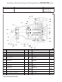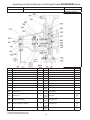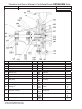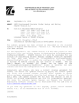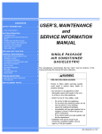
1
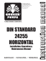
DIN STANDARD
24255
HORIZONTAL
Installation, Operation &
Maintenance Manual
MAINTENANCE • INSTALLATION • OPERATIONS
instruction manual
GUSHER PUMPS, INC.
115 INDUSTRIAL DRIVE
WILLIAMSTOWN, KY 41097
PHONE: 859-824-3100
FAX: 859-824-7428
www.gusher.com
Ruthmann Pumpen
Nothberger Str. 60
D-52249 Eschweiler
Germany
Tel. +49-(0)2403-5595 0
Fax +49-(0)2403-5595 20
Operating and Service Manual
for
Centrifugal Pumps Series
DELTANORM
Size of the pump:
Serial no.:
Year of construction:
Shaft seal:
Bearing frame size:
Operating point:
DN
_ ____________________________
_ ____________________________ _ ____________________________ _ ____________________________ _ ____________________________ _ ____________________________ This operating and maintenance manual contains
important notices and warnings. Please read
carefully before installation, electric connection,
and initiation. Further instructions concerning
components of the pump must be observed.
Operating and Service Manual of Centrifugal Pumps DELTANORM Series
Contents
Page
1
General
3
2
2.1
3
2.7
2.8
Safety Labelling of notices in the operating and
maintenance manual Personnel qualification and training
Dangers with non-observance of the safety notices
Safety-conscious working
Safety notices for the operator Safety notices for service, inspection, and installation
works Unauthorised modifications and production of spare parts
Inadmissible operating methods
3
3.1
3.2
Transport, Intermediate Storage
Transport
Intermediate storage/preservation
5
5
6
4
Designation
6
5
5.1
5.2
5.3
5.4
5.5
5.6.
5.7
5.8
Assembly / Installation
Safety regulations
Check-out before the beginning of assembly
Shaft alignment pump/motor
Connection of the tubing
Standard connections Additional connections Electric connection
Test of sense of rotation
6
6
6
6
7
6
6.1
6.2
Initiation Switching on
Switching off
7
7.1
7.2
7.3
7.4
7.5
7.6
Service / Maintenance
Monitoring
Lubrication
Dismantling
Shaft seal
Ordering of spare parts Stockkeeping of spare parts
8
8.1
8.7
Parts List
Parts list, pump size 32-125 to 65–125, 32-160 to 100-160, 80-200 to 125-200
Parts list, pump size 32-200 to 65-200, 32-250 to125-250
Parts list, pump size 150-200 Parts list, pump size 150-250, 200-250 Parts list, pump size 40-315 to 100-315 Parts list, pump size 125-315 to 150-315,
80-400 to 150-400
Parts list, pump size 40-315H to 80-315H
9
Malfunctions / Causes and Elimination
2.2
2.3
2.4
2.5
2.6
8.2
8.3
8.4
8.5
8.6
3
4
4
4
4
4
5
5
8
8
9
9
9
9
9
10
10
11
11
12
12
13
14
15
16
17
18
19
20
2
Operating and Service Manual of Centrifugal Pumps DELTANORM Series
1.
General
This rotary pump was developed in accordance with our current state of the art, manufactured with greatest care, and was
subject to a continuous quality control during production.
This operating and service manual contains important notices for a safe, appropriate, and economical operation of the
pump.
It is necessary to observe the operating and service manual in order to avoid dangers and to guarantee that the pump is
properly operated.
The type plate shows the pump model and the serial number. We request you to quote these with queries, repeat orders,
and in particular with the order of spare parts.
With receipt of the pump, an arrival inspection shall be carried out, in the course of which the aggregate must be checked for
externally visible damages. Possibly identifiable shipping damages shall be immediately reported to the transport operator.
Within the guarantee period of 6 months, beginning with the date of delivery of the pump ex our works, we assume the repair
and replacement, respectively, of all components which, according to our assessment, are defective or damaged due to
defects of material or fabrication. Wearing parts (e. g. axial face seals), damages due to non-observance of the instructions
for use and inadequate servicing are not covered by the guarantee. The said components must be returned to us free of
charge with the complete servicing records for the purpose of examination and determination of the type and extent of the
guarantee. We shall not assume any responsibility for transport from or to the plant or for possible production damages or
losses of production.
2.
Safety
Before installation and initiation, respectively, this operating and service manual must under all circumstances be read by
all persons involved in installing the pump or who will be operating the aggregate later on. Therefore, this manual should
always be available at the pump.
Other safety notices are listed under other paragraphs and must be observed under all circumstances.
2.1
Labelling of notices in the operating and maintenance manual
The safety notices contained in the operating instructions which may cause threats for persons in case of non-observance
are labelled with the general danger symbol
in case of warning against electric voltage, with
With safety notices, the non-observance of which may cause threats to the machine and its functions, the word
Caution
has been inserted.
Safety notices , which are located directly on the aggregate, must be observed under all circumstances.
3
Operating and Service Manual of Centrifugal Pumps DELTANORM Series
2.2
Personnel qualification and training
The operation and any other handling of the aggregate may only be carried out by qualified personnel.
2.3
Dangers with non-observance of the safety notices
Non-observance may, among other things, result in threats to persons, threats to the environment, or a failure of the
aggregate. Non-observance of safety notices results in the loss of any and all claims for damages.
2.4
Safety-conscious working
The listed safety notices, the existing national accident prevention rules, as well as possible internal job-related, operating,
and safety provisions of the operator shall be observed.
2.5
Safety notices for the operator/operating personnel
-
If hot or cold machine parts cause dangers, these parts must be protected by customer against accidental contact.
-
Protection against accidental contact for moving parts (e. g. coupling) must not be removed from a machine which
is in operation, and must be reinstalled under all circumstances before a new start.
-
Leakage of hazardous materials to be delivered (e. g. explosive, poisonous, hot) must be carried off in such a way
that there is no threat to persons and the environment.
In this process, the statutory provisions must also be complied with under all circumstances.
-
Appropriate measures of precaution must be taken in order to rule out threats caused by electric energy.
2.6
Safety notices for service, inspection, and installation works
Works on the aggregate may only be carried out in switched off condition.
Pumps delivering media injurious to health must be decontaminated.
After completion of the works, all panellings, safety and protective devices must be reinstalled.
With reoperation, the same procedure as with initial operation shall be followed.
Caution
4
Operating and Service Manual of Centrifugal Pumps DELTANORM Series
2.7
Modifications of the aggregate, spare parts
A modification of the aggregate is only permissible after agreement with the manufacturer.
When procuring spare parts, it must be taken care that the acquired parts are original spare parts. The use of other parts
cancels the liability for the resulting consequences.
2.8
Inadmissible operating methods
The operating safety of the pump is only guaranteed with appropriate use.
The purpose of use results from the data stated in the offer or order, as e. g. the flow rate, delivery head, pumping medium,
etc.
3.
Transport, Intermediate Storage
3.1
Transport
With transport of the aggregate, it must be taken care that no defective hoisting gear is used, and that the aggregate is in
a horizontal position during the entire transporting time.
Hoisting gear must not be attached to the shaft end or to the ring loop of the motor.
If the aggregate slips out of the transport suspension, personal injuries and damage to property may occur!
Transport of the complete aggregate
Transport of the pump with free shaft end
5
Operating and Service Manual of Centrifugal Pumps DELTANORM Series
3.2
Intermediate storage
If the pump is supposed to be stored intermediately, the components in contact with the fluid, as far as they are made of
grey cast iron or spheroidal graphite iron, and all other bright components (e. g. shaft ends) must be preserved with the
appropriate agents inhibiting corrosion. In general, the aggregate is to be stored in a dry environment. If the pump is used
in the area of enamelling lines or in conditioning zones, make sure the preservatives are free of silicone.
4.
Designation
DN 80-315 / B
Material code
Size of the pump
Line of products
5.
Mounting / Installation
5.1
Safety regulations
Electrical equipment operated in potentially explosive areas must fulfil the explosion proofness regulations. This is shown
on the type plate of the motor.
With installation in potentially explosive areas, the locally valid explosion proofness provisions and the provisions of the test
certificate provided with the delivery, which was issued by the competent test authority, shall be observed and complied with.
The test certificate provided with the delivery shall be kept in the place of use.
5.2
Check-out before the beginning of mounting
The mounting area must be prepared in accordance with the dimensions of the dimension sheet/space assignment plan.
If the pump is placed on a concrete foundation, sufficient solidity of the concrete (at least BN 150) must be guaranteed.
The surface of the foundation must be horizontal and even.
When mounting the aggregate, it must be aligned horizontally using a water level. If it is necessary to underlay the mounting
plate for the purpose of alignment, make sure the lining sheets are installed on the entire length of the mounting areas.
Mounting plates with a width of 400mm or smaller are made of torsion-free channel steel and need not be grouted in with
concrete.
Wider mounting plates must be grouted with shrinkage-free mortar.
5.3
Shaft alignment pump / motor
Caution
After mounting and fastening the mounting plate, the alignment offset of the pump/motor shaft must be checked and
adjusted, if necessary.
For this purpose, place a ruler on the circumference of the coupling halves at four points which are offset against each other
by 90° each. In addition, take care that the coupling halves have the same distance to each other at the circumference; this
can be checked by means of a feeler gauge.
The deviations must not exceed 0.1mm in radial or axial direction.
The shaft offset must be checked again and adjusted, if necessary, after complete installation at operating temperature and
with oncoming feed pressure.
6
Operating and Service Manual of Centrifugal Pumps DELTANORM Series
5.4
Connection of the tubing
Caution
The tubing shall be installed in such a way that it does not exercise any force or momentum on the connecting flanges of
the pump.
•
•
•
•
5.5
A non-return valve should be installed between the pressure joint of the pump and the shut-off device in order to
prevent the returning fluid from causing a rotation of the pump in opposite direction of the normal sense of rotation
after shutting off the pump, which can lead to damages of the pump when running it again.
In case of operating conditions with short standstill intervals, the use of such a non-return valve is absolutely
necessary in order to guarantee troublefree operation of the pump.
The compressed air gauge should always be installed immediately on the pressure joint of the pump, since the
delivery head and the flow rate of the pump are influenced by resistances in the pipe system.
In order to avoid air locks, the tubing shall be installed ascending towards the pump; with feed pressure, it shall be
installed descending towards the pump.
Standard connections
Item
Connection
1
Deairing
2
Evacuation
Connection
for
Filling and deairing of the impeller casing Evacuation of the
impeller casing
Position of connection
with view towards shaft end
At the pressure joint towards coupling side
At the lower end of the
impeller casing
3
Leakage
Draining of possibly
arising leakage
At the bearing carrier,
bottom right
Connec-
tion size
Used with size of pump
1/4“
All sizes
1/4“
32-125 to 50-125
32-160 to 50-160
32-200 to 50-200
100-160
All other sizes
32-125 to 65-125 32-160 to 65-200
All other sizes
3/8“
3/8“
1/2“
7
Operating and Service Manual of Centrifugal Pumps DELTANORM Series
5.6
Additional connections
Item Connection
Connection for
Position of connection with
view towards shaft end
Connec- Used with size of pump
tion size
1
Compressed air
gauge -
At pressure joint towards
suction side
1/2“
2
Vacuum gauge
-
At suction joint, right
1/4“
1/2“
3a
Flushing connection
inlet
External flushing (e.g. double-acting axial face
seal) At sealing space, bottom left
or right
External flushing (e.g. double-acting axial face seal) At sealing space, top left
3b
Flushing connection outlet Flushing connection inlet cooling/heating axial face At sealing space, bottom
seal
right
4b
Flushing connection outlet
cooling/heating axial face At sealing space, top left
seal
5.7
Electric connection
4a
1/4“
1/4“
3/8“
1/4“
3/8“
3/8“
All other sizes
65-315 to 150-315
80-400 to 150-400
125-200, 100-250,
150-250, 200-250
All other sizes
32-125 to 65-125
32-160 to 50-160
All other sizes
32-125 to 65-125
32-160 to 50-160
All other sizes
All sizes
3/8“
All sizes
The electric connection shall be carried out by appropriately skilled electricians exclusively.
The relevant VDE provisions shall be observed.
The use of a protective motor switch is urgently recommended.
8
65-315 to 150-315
80-400 to 150-400
125-200, 100-250,
150-250, 200-250
Operating and Service Manual of Centrifugal Pumps DELTANORM Series
5.8
Test of sense of rotation
The sense of rotation of all Deltanorm pumps, viewed towards the shaft end of the pump, is to the right.
On the spiral casing of the pump, there is a cast on arrow indicating the sense of rotation, on the ventilator cowl of the driving
motor, there is a sign with an arrow indicating the sense of rotation.
6.
Initiation
Caution
Before initiating the aggregate, make sure that
- the electric connection of the motor is done properly
- all protective devices are installed
- the pump and the suction line are filled with pumping medium, that they have been deaired, and all shut-off devices
on the suction side are open
- the sense of rotation has been checked
- with pumps with double-acting axial face seal, the sealing water supply is provided.
Caution
Running dry immediately leads to damages of the pump.
6.1
Switching on
Caution
The pump may only be switched on with closed shut-off device on the pressure side! After the full speed has been reached,
the shut-off device is slowly opened, and adjusted to the operating point. Make sure that the delivery head specified in the
offer or order is observed.
6.2
Switching off
Caution
Close the shut-off device on the pressure side.
The shut-off device on the suction side must remain open.
Switch off the motor.
Pumps with double-acting axial face seal (in particular with delivery of lacquers or media tending to crystallise out) must be
impinged on with sealing water during standstill.
With risk of frost or longer standstill periods, the pump must be evacuated.
7.
Service / Maintenance
Works may principally only be carried out if the electric connections have been disconnected and the pump has been
secured against undesired switching on.
9
Operating and Service Manual of Centrifugal Pumps DELTANORM Series
7.1
Monitoring
The following points must be observed:
-
-
-
-
-
-
7.2
Running dry must be avoided under all circumstances
The pump must run free from vibrations
The max. room temperature must not exceed 40°C
The pump must not be operated against a closed shut-off device for a longer period of time
The max. number of switching operations must not exceed 6 starting cycles per hour
The elastic elements of the shaft coupling must be checked for wear
Lubrication
The used rolling bearings are provided with grease lubrication for the designed service life of the bearings.
Pumps of special designs with regreasing appliances require the following lubricating intervals:
1000 1/min
1500 1/min
3000 1/min
approx. every 6000 operating hours
approx. every 4000 operating hours
approx. every 2000 operating hours
After 1000 operating hours, but no later than after 2 years, the bearings should be disassembled, washed out, provided with
a fresh grease filling, and remounted.
Depending on the operating conditions (higher ambient temperature, dust, high air moisture, etc.), the regreasing intervals
have to occur more often.
Required grease quantity per bearing:
Bearing carrier size
Size 1
Size 2, Size 2/1
Size 2H
Size 3, Size 3/1
Grease quantity per
bearing
5g
8g
14g
12g
Caution
If the bearings are overlubricated (too much grease in the bearing), there is a danger of overheating of the bearings.
We recommend the following or comparable greases:
Manufacturer
ESSO
SHELL
BP
Type
Beacon EP3
Shell Alvania R2
BP Energrease LS3
10
Operating and Service Manual of Centrifugal Pumps DELTANORM Series
7.3
Dismantling
Dismantling is carried out according to the following steps:
1. Make sure the personnel is appropriately qualified.
2. Secure the aggregate against switching on.
3. Close shut-off devices on suction and pressure side.
4. If necessary, let the aggregate cool down to room temperature.
5. Evacuate the pump casing.
6. Disconnect current supply to the motor.
7. Dismount additional connections.
8. Remove coupling protection.
9. Detach motor from mounting plate and remove from the plate.
10. Disconnect flanges on suction and pressure side from the tubing.
11. Detach support foot of the pump from the mounting plate.
12. The spiral casing remains in the tubing and on the mounting plate.
13. Unscrew the hexagon nuts on the collar of the pump casing.
14. Pull out bearing carriers completely with pressure lid and impeller.
15. With larger pumps, the bearing carrier must be supported or under-propped on the impeller side when pulling out in
order to avoid tipping over.
16. Release circlip securing ring (093).
17. Unscrew impeller nut (922) and remove from the shaft together with circlip (093).
18. Pull impeller (230) off the shaft (if necessary, with the aid of a take-off).
19. Remove feather key (940.1) from the shaft.
20. Remove impeller distance bush from the shaft.
21. Remove distance washer from the shaft.
22. Loosen sealing lid and pull out of the casing towards the bearing carrier.
23. Remove casing cover (with some pumps, the casing cover is cramped, with others, the nuts on the collar of the
bearing carrier must be unscrewed).
24. Pull axial face seal off the shaft.
25. Remove sealing lid from the shaft.
26. Remove stationary ring of the axial face seal together with O-ring from the sealing lid.
27. Unscrew cap pieces of the bearings (330 and 360) from the bearing carrier, and take off.
28. Pull shaft together with bearing out of the bearing carrier.
7.4
Shaft seal
In order to replace the shaft seal, please proceed as described under section 7.3 item 1 to 26. Before assembly, first clean
the shaft or, if provided, the shaft sleeve, and check whether there is any scoring on the seating of the shaft seal. If so, the
shaft or protective shaft sleeve must be replaced. Now clean the sealing lid.
Assembly occurs in reverse order of dismantling described above.
When mounting the axial face seal, extreme cleanliness must be observed, and work has to be carried out with greatest
care.
Damage to the sealing surfaces and sealing rings must be avoided under all circumstances; the seal must never be placed
on the sealing surfaces (polished side of the sealing rings), since even slight scratches on the sealing surface lead to
immediate failure of the seal.
Clean the shaft or, if provided, the shaft sleeve and the seating of the seal in the sealing lid from possible deposits, and
subsequently clean the components.
•
•
•
•
•
Oil or grease must never be used when mounting the axial face seal.
Moisten the O-ring of the stationary ring of the axial face seal with water, and push the stationary ring together with
the O-ring by hand into the sealing lid.
Slide the sealing lid together with the stationary ring over the shaft and fasten it on the collar of the bearing
casing.
Slide the axial face seal onto the shaft until the slide faces of stationary and rotating component touch.
The assembly of the pump occurs in reverse order of dismantling described above.
11
Operating and Service Manual of Centrifugal Pumps DELTANORM Series
7.5
Ordering of spare parts
For spare part orders, we always need the following information provided on the type plate of the pump:
Model: Serial no.:
e.g. DN100-315/B
e.g. 0385-005
as well as the part number and designation which you will find in this manual.
7.6
Stockkeeping of spare parts
For continuous operation of two years, we recommend keeping stock of the following spare parts:
Part no.
Part designation
015
046
002
054
053
041.1
041.2
005
038
Shaft
Shaft sleeve*
Impeller
Wear ring, suction side
Wear ring, pressure side
Radial ball bearing
Radial ball bearing
Casing seal
Shaft seal
O-ring (sealing lid)
Circlip
049
Number of pumps (incl. backing pumps)
1
1
1
1
1
1
1
1
2
1
1
2
2
1
1
1
1
1
2
2
4
2
2
4
3
1
1
1
1
1
2
2
6
3
3
6
* only if provided
12
4
2
2
1
1
1
4
4
8
4
4
8
5
2
2
2
2
2
4
4
10
5
5
10
6 and more
50%
50%
30%
30%
30%
100%
100%
200%
100%
100%
200%
Operating and Service Manual of Centrifugal Pumps DELTANORM Series
8.1 Parts list
Size of pumps
32-125 to 65-125
32-160 to 100-160
80-200 to 125-200
Item
001
002
003
005
013
Description
Impeller casing
Impeller
Casing cover
Casing seal
Splash ring
Number
1
1
1
1
1
014
Bearing casing
1
015
Shaft
1
033
Support foot
1
036
Seal gland
1
037
Flushing ring 2)
1
038
Packing ring2)
4
039
Cap piece of bearing
2
040
Seal of cap piece of bearing
2
041
Thrust bearing
2
Item
042
046
047
048
049
050,
051
054
055,
057
056,
058
100-0,
100-1
102-0,
102-1
110-0,
110-1
115-0,
115-1
only with pumps of special design
2)
not with pumps with axial face seal
3)
may also be replaced by Teflon tape
1)
13
Description
Joint gasket 1)
Protective shaft sleeve 1)
Seal of protective shaft sleeve 1)
Impeller nut
Circlip
Number
2
1
1
1
1
Feather key
1
Split ring
1
Screw plug
1
Joint gasket 3)
1
Stud bolt
Hexagon bolt
Hexagon nut
Plain washer
8/12
2
1
6
8/12
2
2
1
Operating and Service Manual of Centrifugal Pumps DELTANORM Series
8.2 Parts list
Size of pumps
32-200 to 65-200
32-250 to 125-250
Item
001
002
003
005
013
Description
Impeller casing
Impeller
Casing cover
Casing seal
Splash ring
Number
1
1
1
1
1
014
Bearing casing
1
015
Shaft
1
033
Support foot
1
036
Seal gland
1
037
Flushing ring 2)
1
038
Packing ring 2)
4
039
Cap piece of bearing
2
040
Seal of cap piece of bearing
2
041
Thrust bearing
2
only with pumps of special design
not with pumps with axial face seal
3)
may also be replaced by Teflon tape
Item
042
046
047
048
049
050,
051
054
055,
057
056,
058
100-0,
100-1
100-2
102-0,
102-1
110-0,
110-1
110-2
115-0,
115-1
1)
2)
14
Description
Joint gasket 1)
Protective shaft sleeve 1)
Seal of protective shaft sleeve 1)
Impeller nut
Circlip
Number
2
1
1
1
1
Feather key
1
Split ring
1
Screw plug
1
Joint gasket 3)
1
Stud bolt
Hexagon bolt
Hexagon nut
Plain washer
8/12
6/8
2
1
6
8/12
6/8
2
2
1
Operating and Service Manual of Centrifugal Pumps DELTANORM Series
8.3 Parts list
Size of pumps
150-200
Item
001
002
003
005
Description
Impeller casing
Impeller
Casing cover
Casing seal
Number
1
1
1
1
Item
042
046
047
048
Description
Joint gasket 1)
Protective shaft sleeve 1)
Seal of protective shaft sleeve 1)
Impeller nut
013
Splash ring
1
Circlip
1
014
Bearing casing
1
Feather key
1
015
033
Shaft
Support foot
1
1
049
050,
051
053
054
Split ring, casing cover
Split ring, suction side
1
1
036
Seal gland
1
055,
057
Screw plug
1
037
Flushing ring 2)
1
056,
058
Joint gasket 3)
1
038
Packing ring 2)
4
039
Cap piece of bearing
2
040
Seal of cap piece of bearing
2
041
Thrust bearing
2
100-0,
100-1
102-0,
102-1
110-0,
110-1
115-0,
115-1
only with pumps of special design
not with pumps with axial face seal
3)
may also be replaced by Teflon tape
1)
2)
15
Stud bolt
Hexagon bolt
Hexagon nut
Plain washer
Number
2
1
1
1
8/12
2
1
6
8/12
2
2
1
Operating and Service Manual of Centrifugal Pumps DELTANORM Series
8.4 Parts list
Size of pumps
150-250, 200-250
Item
001
002
003
005
013
Description
Impeller casing
Impeller
Casing cover
Casing seal
Splash ring
Number
1
1
1
1
1
014
Bearing casing
1
015
033
Shaft
Support foot
1
1
036
Seal gland
1
037
Flushing ring 2)
1
038
Packing ring 2)
4
039
Cap piece of bearing
2
040
Seal of cap piece of bearing
2
041
Thrust bearing
2
Item
042
046
047
048
049
050,
051
053
054
055,
057
056,
058
100-0,
100-1
102-0,
102-1
Description
Joint gasket 1)
Protective shaft sleeve 1)
Seal of protective shaft sleeve 1)
Impeller nut
Circlip
Feather key
1
Split ring, casing cover
Split ring, suction side
1
1
Screw plug
1
Joint gasket 3)
1
Stud bolt
Hexagon bolt
110-0,
Hexagon nut
110-1
115-0,
Plain washer
115-1
only with pumps of special design
not with pumps with axial face seal
3)
may also be replaced by Teflon tape
1)
2)
16
Number
2
1
1
1
1
8/12
2
1
6
8/12
2
2
1
Operating and Service Manual of Centrifugal Pumps DELTANORM Series
8.5 Parts list
Item
001
002
003
005
Description
Impeller casing
Impeller
Casing cover
Casing seal
013
Size of pumps
40-315 to 100-315
Number
1
1
1
1
Item
042
046
047
048
Splash ring
1
014
Bearing casing
1
015
033
Shaft
Support foot
1
1
036
Seal gland
1
037
Flushing ring 2)
1
038
Packing ring 2)
4
039
Cap piece of bearing
2
040
Seal of cap piece of bearing
2
041
Thrust bearing
2
049
050,
051
053
054
055,
057
056,
058
100-0,
100-1
100-2
102-0,
102-1
110-0,
110-1
110-2
115-0,
115-1
only with pumps of special design
not with pumps with axial face seal
3)
may also be replaced by Teflon tape
1)
2)
17
Description
Joint gasket 1)
Protective shaft sleeve 1)
Seal of protective shaft sleeve 1)
Impeller nut
Number
2
1
1
1
Circlip
1
Feather key
1
Split ring, casing cover
Split ring, suction side
1
1
Screw plug
1
Joint gasket 3)
1
Stud bolt
Hexagon bolt
Hexagon nut
Plain washer
8/12
6/8
2
1
6
8/12
6/8
2
2
1
Operating and Service Manual of Centrifugal Pumps DELTANORM Series
8.6 Parts list
Size of pumps
125-315 to 150-315
80-400 to 150-400
Item
001
002
003
005
013
Description
Impeller casing
Impeller
Casing cover
Casing seal
Splash ring
Number
1
1
1
1
1
014
Bearing casing
1
015
033
Shaft
Support foot
1
1
036
Seal gland
1
037
Flushing ring 2)
1
038
Packing ring 2)
4
039
Cap piece of bearing
2
040
Seal of cap piece of bearing
2
041
Thrust bearing
2
only with pumps of special design
not with pumps with axial face seal
3)
may also be replaced by Teflon tape
Item
042
046
047
048
049
050,
051
053
054
055,
057
056,
058
100-0,
100-1
100-2
102-0,
102-1
110-0,
110-1
110-2
115-0,
115-1
1)
2)
18
Description
Joint gasket 1)
Protective shaft sleeve 1)
Seal of protective shaft sleeve 1)
Impeller nut
Circlip
Number
2
1
1
1
1
Feather key
1
Split ring, casing cover
Split ring, suction side
1
1
Screw plug
1
Joint gasket 3)
1
Stud bolt
Hexagon bolt
Hexagon nut
Plain washer
8/12
6/8
2
1
6
8/12
6/8
2
2
1
Operating and Service Manual of Centrifugal Pumps DELTANORM Series
8.7 Parts list
Size of pumps
40-315H to 80-315H
Item
001
002
003
005
013
Description
Impeller casing
Impeller
Casing cover
Casing seal
Splash ring
Number
1
1
1
1
1
014
Bearing casing
1
015
033
Shaft
Support foot
1
1
036
Seal gland
1
037
Flushing ring 2)
1
038
Packing ring 2)
4
039
Cap piece of bearing
2
040
Seal of cap piece of bearing
2
041
Thrust bearing
2
only with pumps of special design
not with pumps with axial face seal
3)
may also be replaced by Teflon tape
Item
042
046
047
048
049
050,
051
053
054
055,
057
056,
058
100-0,
100-1
100-2
102-0,
102-1
110-0,
110-1
110-2
115-0,
115-1
1)
2)
19
Description
Joint gasket 1)
Protective shaft sleeve 1)
Seal of protective shaft sleeve 1)
Impeller nut
Circlip
Number
2
1
1
1
1
Feather key
1
Split ring, casing cover
Split ring, suction side
1
1
Screw plug
1
Joint gasket 3)
1
Stud bolt
Hexagon bolt
Hexagon nut
Plain washer
8/12
6/8
2
1
6
8/12
6/8
2
2
1
Operating and Service Manual of Centrifugal Pumps DELTANORM Series
9.
Malfunctions / Causes
X
X
X
X
X
X
X
X
X
X
X
Cavitation
(noise
development)
X
Motor
becomes hot
X
Vibrations
X
X
Pumping
output stops
after start
Pressure
build-up too
little
Pump not filled, tubing is air bound
Speed to low
Speed too high
Suction line leaky
Air or gas lock in the pumping medium
Counterpressure too high
Suction head too high
Feed pressure too low with hot pumping medium
Tubing on suction side not sufficiently covered with liquid
Density of pumping medium too high
Viscosity of pumping medium too high
Impeller obstructed
Tubing on suction side obstructed
Wrong sense of rotation
Split rings worn out
Impeller damaged
Driving motor defective
Voltage too low
Frequency too low
Running on 2 phases
Installation / foundation unstable
Motor – pump not well aligned
Bearing worn out
Balance error in the impeller
Impeller too small
Pumping
output too
little
Cause
No pumping
output
Malfunction
X
X
X
X
X
X
X
X
X
X
X
X
X
X
X
X
X
X
X
X
X
X
X
X
X
X
X
X
X
X
X
X
X
X
X
X
X
X
X
X
20
X
X
Ruthman...
Another Word for Innovation
Gusher Pumps is a Division of
Ruthman Companies
Corporate Headquarters
1212 Streng Street
Cincinnati, OH 45233
Phone: 513-559-1901
Fax: 513-559-0035
Web: www.ruthmancompanies.com
Gusher Pumps of Dry Ridge
22 Ruthman Drive
Dry Ridge, KY 41035
Phone: 859-824-5001
Fax: 859-824-3011
Web: www.gusher.com
Gusher Pumps of Williamstown
115 Industrial Drive
Williamstown, KY 41097
Phone: 859-824-3100
Fax: 859-824-7248
Web: www.gusher.com
Gusher Pumps of Cincinnati
1212 Streng Street
Cincinnati, OH 45233
Phone: 513-559-1901
Fax: 513-559-0035
Web: www.gusher.com
Gusher Pumps of California
8226 Salt Lake Avenue
Cudahy, CA 90201
Phone: 323-773-0847
Fax: 323-773-0958
Email: [email protected]
Gusher Pumps of New Castle
403 North Ninth Street
New Castle, IN 47362
Phone: 765-529-5624
Fax: 765-521-0008
Email: [email protected]
BSM Pump Corp.
180 Frenchtown Road
North Kingstown, RI 02852
Phone: 401-471-6350
Fax: 401-471-6370
Web: www.bsmpump.com
Nagle Pumps
1249 Center Avenue
Chicago Heights, IL 60411
Phone: 708-754-2940
Fax: 708-754-2944
Web: www.naglepumps.com
It began in 1913, servicing mechanical components of the
steamboats on the Ohio River. The
company founder, Alois Ruthman,
was a man of vision and saw part
of the future of the company was
in the development of a reliable industrial pump.
In 1924, with the conception of the first vertical ball bearing sealless centrifugal pump, Ruthman Pump and Engineering furthered
the design on a unit with a one piece motor driven shaft. The
pump was called “Gusher”, giving birth to the trade name Gusher Pumps, and the coining of the term “coolant pump”.
Wanting to carry on the tradition of quality and reliability started
by his father, Thomas R. Ruthman joined the company in 1949. In
the early 1990’s Thomas R. Ruthman’s son, Thomas G. Ruthman
joined the company, continuing this same tradition. Maintaining
the reputation of Gusher Pumps by innovation and customer service, the company has grown to service companies worldwide.
Wagner Processing – Bay Area
23510 Bernhardt Street
Hayward, CA 94545
Phone: 510-786-3929
Fax: 510-786-3722
Web: www.wagnerprocess.com
Wagner Processing – Central Valley
3675 N. Wilcox Street #C
Stockton, CA 95215
Phone: 209-931-0100
Fax: 209-931-7910
Web: www.wagnerprocess.com
Great Lakes Pump & Supply Co.
1075 Naughton
Troy, MI 48083
Phone: 248-528-9100
Fax: 248-528-9015
Web: www.greatlakespump.com
Process Systems, Inc.
Michigan, Main Headquarters
23633 Pinewood
Warren, MI 48091
Phone: 586-757-5711
Fax: 586-758-6996
Web: www.INFOatpsi4pumps.com
Indiana
485 N State Route 3431 South
Mellott, IN 47958
Phone: 765-295-2206
Fax: 765-295-2243
Web: www.process-systems-inc.com
Worldwide:
Ruthmann Pumpen
Northberger Strabe 60
Eschweiler Germany D-52249
Phone: +49 (0) 2403 5595 0
Fax: +49 (0) 2403 5595 20
Web: www.ruthmannpumpen.de
Birmingham Pump
Unit 7 Network Park
Duddeston Mill Road
Saltley, Birmingham England B81AU
Phone: +44 (0) 121 503 3000
Fax: +44 (0) 121 503 3002
Web: www.birminghampumps.co.uk
Guan Shen Industrial Pumps
(Shanghai) Company
Gusher Pumps (Shanghai) Co., Ltd.
Building D, Room 416
No. 188 East Jiagwan Road
Shanghai, 200081
P.R. CHINA
Phone: 86-21-33872056
Phone: 86-21-33872058
Fax: 86-21-33872057
86-21-33872056
86-21-33872058
86-21-33872057