1
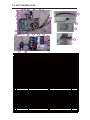
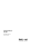
SPLIT-TYPE AIR CONDITIONER
INDOOR UNIT
OUTDOOR UNIT
Model Code : AR09HSFSJWKNCV AR09HSFSJWKXCV
AR12HSFSJWKNCV AR12HSFSJWKXCV
AR18HSFSJWKNCV AR18HSFSJWKXCV
AR24HSFSJWKNCV AR24HSFSJWKXCV
Basic Code :
AIR CONDITIONER
AR09HSFSHWKNCV AR09HSFSHWKXCV
AR12HSFSHWKNCV AR12HSFSHWKXCV
AR18HSFSHWKNCV AR18HSFSHWKXCV
AR24HSFSHWKNCV AR24HSFSHWKXCV
CONTENTS
1. Precautions
2. Product Specifications
3. Alignment and Adjustments
4. Disassembly and Reassembly
5. Disassembly WIFI
AR09HSFSJWKXCV
AR12HSFSJWKXCV
6. Electrical Parts List
7. Wiring Diagram
8. PCB Diagram
9. Operating Instructions
10. Troubleshooting
11. Block Diagram
AR18HSFSJWKXCV
AR24HSFSJWKXCV
12. Reference Sheet
Contents
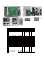
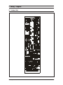
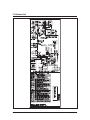
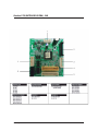
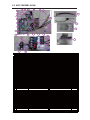
8. PCB Diagram 8-1
8-1 Indoor Unit·····························································································································································
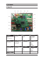
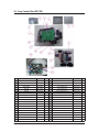
8-2 Outdoor PCB ························································································································································
8-3 Wire connecting the indoor unit terminal blocks ·················································································
8-1
8-2
8-8
9. Operating Instructions 9-1
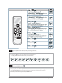
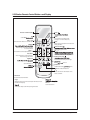
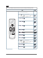
9-1 Name of Each Part ··············································································································································
9-2 Wireless Remote Control-Buttons and Display·······················································································
9-1
9-2
10. Troubleshooting 10-1
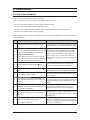
10-1 Items to be checked first······························································································································· 10-1
10-2 Communication Error ····································································································································· 10-2
10-3 PCB Inspection Method································································································································· 10-37
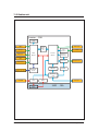
11. Block Diagram 11-1
11-1 Indoor unit ·························································································································································· 11-1
11-2 Outdoor unit······················································································································································· 11-2
12. Reference Sheet12-1
12-1 Low Refrigerant Pressure Distribution·····································································································
12-2 Pressure & Capacity mark······························································································································
12-3 Q & A for Non-trouble·····································································································································
12-4 Cleaning /Filter Change·································································································································
12-5 Installation···························································································································································
12-6 Installation Diagram of Indoor Unit and Outdoor Unit····································································
2
12-1
12-1
12-2
12-5
12-6
12-7
Samsung Electronics
Contents
1. Precautions ············································································································· 1-1
1-1 Installing the air conditioner··························································································································
1-2 Power supply and circuit breaker·················································································································
1-3 During operation ················································································································································
1-4 Disposing of the unit·········································································································································
1-5 Others ······································································································································································
1-1
1-1
1-1
1-2
1-2
2. Product Specifications······························································································· 2-1
2-1 The Feature of Product ·····································································································································
2-2 Product Specifications ······································································································································
2-3 The Comparative Specifications of Product·····························································································
2-4 Accessory and Option Specifications ·········································································································
2-1
2-2
2-6
2-8
3. Alignment and Adjustments ········································································ 3-1
3-1 Test Mode·······························································································································································
3-2 Outdoor LED Display Error and Check Method ·····················································································
3-3 Setting Option Setup Method·······················································································································
3-4 Setting Option Setup Method·······················································································································
3-1
3-2
3-5
3-9
4. Disassembly and Reassembly ······································································ 4-1
4-1. Indoor Unit·························································································································································· 4-1
4-2. Outdoor Unit························································································································································ 4-2
5. ASSY CONTROL ··························································································· 5-1
5-1 ASSY CONTROL IN ··············································································································································
5-2 Assy Control Out ················································································································································
5-1
5-2
6. Electrical Parts List ························································································ 6-1
6-1 INDOOR MAIN PCB ·········································································································· ································· 6-1
6-2 INDOOR SUB PBA··················································································································
··································· 6-5
6-3 INDOOR SUB PBA····················································································································································· 6-6
6-4 OUTDOOR MAIN PBA- 9K/12K ····················································································· ··················
··················· 6-7
6-5 OUTDOOR MAIN PBA- 18K···································································································
··················
·················· 6-13
6-6 OUTDOOR MAIN PBA- 24K··········································································································
························ 6-21
6-7 OUTDOOR MAIN PBA- 24K····························································································································
······ 6-25
7. Wiring Diagram······························································································ 7-1
7-1 Indoor Unit·····························································································································································
7-2 Outdoor Unit ························································································································································
Samsung Electronics
7-1
7-2
1
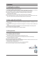
1. Precautions
1-1 Installing the air conditioner
O Uses should not install the air conditioner by themselves.
Ask the dealer or authorized company to install the air conditioner ecept window-type air conditioner in U.S.A and Canada.
O If you dont install the air conditioner properly, it may cause a fire, a water leakage or an electric shock.
O You must install the air conditioner according to the national wiring regulations and safety regulations.
O Install the indoor unit higher than 2.5m from the floor to avoid the injury caused by the operation of the fan.
(ecept the window-type air conditioner)
O The manufacturer is not responsible for any accidents or injury caused by an incorrect installation.
O When installing the built-in type air conditioner, keep all electric cables such as the power cable and the connection cord in
pipes, ducts, or cable channels to protect them from the danger of impact or any other incidents.
1-2 Power supply and circuit breaker
O If the power cord of the air conditioner is damaged, it must be replaced by the manufacturer or a ualified person in order
to avoid a hazard.
O The air conditioner must be plugged into an independent circuit if applicable or connect the power cable to the auiliary circuit
breaker.
An all pole disconnection form the power supply must be incorporated in the fied wiring with a contact opening of>3mm.
O Do not etend an electric cord to the air conditioner.
O The air conditioner must be plugged in after you complete the installation.
1-3 During operation
O Do not repair the air conditioner at your discretion.
It is recommended to contact a service center directly.
O Never spill any kind of liuid on the air conditioner.
If this happens, turn off the air conditioner and contact an authorized service center.
O Do not insert anything between the airflow blades to prevent damage of the inner fan and conseuent injury.
Keep children away from the air conditioner.
O Do not place any obstacles in front of the air conditioner.
O Do not spray any kind of liuid into the indoor unit. If this happens, turn off the air conditioner and contact a service center.
O Make sure that the air conditioner is well ventilated at all times.
Do not place a cloth or other materials over it.
O Remove the batteries if you dont use the remote control for a long time. (If applicable)
O Use the remote control within 7 meters from the indoor unit. (If applicable)
Samsung Electronics
1-1
1-4 Disposing of the unit
O Before the throwing out the air conditioner, remove the batteries from the remote control.
O When you dispose of the air conditioner, consult your dealer. If pipes are removed incorrectly, refrigerant may blow out
and cause air pollution. When it contacts with your skin, it can cause skin injury.
O The package of the air conditioner should be recycled or disposed of properly for environmental reasons.
1-5 Others
O
O
O
O
1-2
Never store or load the air conditioner upside down or sideways to prevent the damage to the compressor.
Young children or infirm persons should be always supervised when they use the air conditioner.
Ma current is measured according to IEC standard for safety.
Current is measured according to ISO standard for energy efficiency.
Samsung Electronics
2. Product Specifications
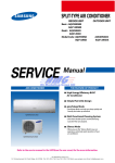
2-1 The Feature of Product
䒲 #2 step cooling
- Get cool quickly and keep cool comfortably without shivering
䒲 #Single user mode
- No worrying about the electricity bill, even using it when you're alone.
䒲 #Crystal gloss design
- Uniquely stylish and innovative design to enhance your life and home
䒲 #Smart Wi-Fi
- Control air conditioner anytime and anywhere
䒲 #Smart Installation
- Get the confidence that it's perfectly installed
䒲 #Smart Installation
- Get the confidence that it's perfectly installed
䒲 #Smart Check
- Don’t worry about the trouble-shooting in your home
䒲 #Triple Protector Plus
- Use longer without damage in unsuitable conditions
䒲 #Easy Installation
- Secure the easy Installation of Indoor unit and pipe connection
䒲 #Easy Filter
- Quick and easy to clean filter saves time and effort
Samsung Electronics
2-1
E icienc
t(Net)
B ow er
Oi T pe
Compressor
Drain Hose
Re ri erant Pipe
Wei
Outer Dimension
Pow er Factor
Operatin Current
Pow er Consumtion
Pow er
Ener
Ratio
Noise
t
(Low /St /Max)
Heatin
4.5
4
-
2- 2
-15 24℃
Heatin
Samsung Ele ctr onic s
-10 46℃
Coo in
None
cc
2Row 24Step
2Row 14Step
1Row 10Step
Rate Output(W)
EEV
-
Resin/stee /AC
Resin/stee /AC
Prope er
T pe
Cross- ow
EEV
-
Prope er
None
-15 24℃
-10 46℃
3.14
3.88
3.7
550*20
.52
6.35
53
1023* 11*413
EEV
-
Prope er
2Row 36Step
-
Resin/stee /AC
-15 24℃
-10 46℃
None
2000
2Row 16Step
1Row 12Step
-
Resin/stee /AC
Cross- ow
-
-
-
UG4T200FUAE4SS
14
1123*354*384
0
0
1.5/7.3/10.5
1.8/6.2/ .7
300/1630/2100
380/1360/2200
550*20
.52
6.35
71.5
1051*1045*417
Prope er
-15 24℃
-10 46℃
None
2300
-
2Row 42Step
EEV
-
Resin/stee /AC
-
-
2Row 16Step
1Row 12Step
Resin/stee /AC
Cross- ow
-
-
UG8T300FUBJUSS
14
1123*354*384
0
0
2.6/11.5/1 .0
3.2/8.3/14.0
480/2520/4200
600/1800/3150
1p ase, 208-230V , 60H
60
3.58
57
1p ase, 208-230V , 60H
Samsung Ele ctr onic s
2Row 24Step
-
Resin/stee /AC
1250
2Row 14Step
1Row 10Step
-
Resin/stee /AC
Cross- ow
-
-
-
Rate Output(W)
-
-
UG T115FUAE SS
-
T pe
UG T115FUAE SS
.52
.52
37
26*640*384
550*20
6.35
11
56*317*335
6.35
37
550*20
11
26*640*384
85
85
56*317*335
1.3/4. /8.3
1.3/4.1/6.5
85
1.5/4.1/5.3
1.5/2. /3.2
85
220/880/1150
1 0/1060/1800
220/600/700
1 0/880/1400
1p ase, 208-230V , 60H
4.3
4.4
1p ase, 208-230V , 60H
53
51
Proterction Device(OLP)
Operation con ition ran e
15/46/75
47/45
50/4
15/41/6
15/54/72
15/63/103
46
2.2/7. 13/12.00
/6.00
15/47/73
/3.
1.2/6.04/8.00
Wa -mounte
2.60/6.448/ .30
Wa -mounte
24
1.6/5.275/7.00
1
15/53/67
45/44
15/55/82
0.
/3.52/5.20
15/38/45
0.
1250
motor
T pe
Motor
T pe
mm
Gas
L*D
mm
mm
Wi t *Hei
*Dept
Li ui
(St )
A
(Low /St /Max)
W
(Low /St /Max)
p -V-H
W/W
(St )
Heatin
Coo in
Heatin
Coo in
Heatin
Coo in
Heatin
Coo in
Heatin
B
(H/L)
H
Coo in
(Low /St /Max)
Heatin
Coo in
/2.64/3.20
/3.52/4.00
Wa -mounte
0.
Wa -mounte
12
0.
0
Re ri erant to C an e(R410A)
Free er Oi Capacit
Re ri erant Contro Unit
Heat Exc an er
Si e
Pow
Per ormance
Runnin Fre uenc
Capacit
KW
Coo in
T pe
2-2 Product Specifications
2- 3
2- 6
Air Puri in S stem
Noise
Outer Dimension
Net Wei t
Desi n
ITEM
In oor Unit
Out oor Unit
In oor Unit
Out oor Unit
In oor Unit
Out oor Unit
Fi ter
Out oor Unit
In oor Unit
MODEL
2-3 The Comparative Specifications of Product
Samsung Ele ctr onic s
11
37
56*317*335
26*640*384
45
51
FULL HDFILTER
AR0 HSFSJWK/CV
Samsung Ele ctr onic s
11
37
56*317*335
26*640*384
47
53
FULL HDFILTER
FULL HDFILTER
14
53
1123*354*384
1023* 11*413
46
57
Deve op Mo e
AR12HSFSJWK/CV
AR18HSFSJWK/CV
FULL HDFILTER
14
71.5
1123*354*384
1051*1045*417
50
60
AR24HSFSJWK/CV
2- 7
2-4 Accessory and Option Specifications
Item
Descriptions
Code-No.
Installation Plate
09/12 (04 frame)
DB90-07732A
1
Installation Plate
18/24/30 (05 frame)
DB90-07731A
1
Remote controller
DB93-14195G
1
Batteries for Remote controller
4301-000121
2
User’s & Installation Manual
DB68-04405A
1
Wi-Fi Manual
DB68-04419A
1
Remote Control Holder
-
-
M4x10 Tapped Screws
DB97-23032A
2
M4 x 16 Tapped Screws
DB97-11984A
2
Drain Plug
DB67-20011A
1
Indoor unit case
Outdoor unit case
Rubber Leg
2-8
DB73-20134A
4
Samsung Electronics
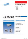
3. Alignment and Adjustments
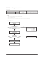
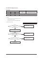
3-1 Test Mode
Q How to Approach Test Mode
You can approach the test mode by pressing the on/off switch of
indoor unit for 5 seconds.
Q Test mode operation option
After installing the air conditioner, check whether each subordinate is normally operated or not by operating the test mode.
When an Error occurs, display the Error Mode.
● Operation Mode : Cool mode. operate the cool mode by operating the compressor by force without the compressor ON/OFF
according to the set temperature/indoor temperature. (Do not follow the antifreeze control)
● Up-down louver : Up-down swing mode
● Indoor Fan : Turbo
●
●
Note
Because the teat mode operate the cool mode by force not related to the set temperature / indoor
temperature, check whether each subordinate is operated normally or not after completing installation
and must turn off the power of the air conditioner.
Samsung Electronics
3-1
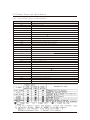
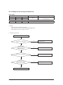
'LVSOD\(UURUDQG&KHFN0HWKRG
,QGRRU'LVSOD\(UURUDQG&KHFN0HWKRG
(5 5 2 5 0 2 ' (
((
' (6 & 5 ,3 7 ,2 1
&RPPXQLFDWLRQ(UURU,QGRRU
2XWGRRU
(
52207+VHQVRUHUURU
(
,1'2250,',1'225,13,3(7+VHQVRUHUURU
(
)DQ(UURU,QGRRU
(
((3520(UURU,QGRRU
(
2SWLRQ(UURU
(
7LPHRXW&RPP,QY0LFRP
(
2877+2XWGRRU7HPSHUDWXUH6HQVRU(UURU
0DLQ0LFRP
(
&217+&RQG7HPSHUDWXUH6HQVRU(UURU
(
',67+'LVFKDUJH7HPSHUDWXUH6HQVRU(UURU
(
',67+'LVFKDUJH7HPSHUDWXUH2YHU(UURU
(
((9RU9DOYH&ORVHHUURU6HOIGLDJQRVLV
(
3URKLELW2SHUDWLRQ&RQGLWLRQ(UURU+HDWLQJ
(
3URKLELW2SHUDWLRQ&RQGLWLRQ(UURU&RROLQJ
(
)DQ(UURU2XWGRRU
(
&RPS6WDUWLQJ(UURU
(
$&,QSXW,B/LPLW7ULS(UURU
(
,302YHU&XUUHQW2&(UURU
(
&RPS9BOLPLW,BOLPLW(UURU
(
'&/LQN9ROWDJH8QGHU2YHU(UURU
(
&RPS:LUH0LVVLQJ(UURU
(
&XUUHQW6HQVRU(UURU
(
'&/LQN9ROWDJH6HQVRU(UURU
(
((3520'DWD(UURUQRGDWD
(
((3520'DWD(UURU0DLQ0LFRP
(
+HDWVLQN6HQVRU(UURU
(
2YHU9ROWDJH3URWHFWLRQ(UURU
(
3)&2YHU/RDG(UURU
(
,QSXW&XUUHQW6HQVRU(UURU
(
$&,QSXW9ROWDJH6HQVRU(UURU
(
+HDWVLQN2YHU7HPSHUDWXUH(UURU
(
*DV/HDN(UURU
,QY0LFRP
6DPVXQJ(OHFWURQLFV
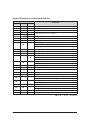
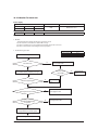
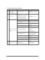
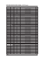
Outdoor LED Display Error and Check Method (9K/12K)
LED PATTERN
DESCRIPTION
YEL
GRN
RED
ل
ل
ل
Power off/VDD NG
م
م
م
Power ON reset(1sec)
ل
ሱ
م
Normal Operation
ل
ل
م
ل
م
م
ل
ل
ሱ
IPM Over Current(O.C) Error
ل
ሱ
ل
Comp Starting Error
ل
م
ل
EEPROM Data Error (no data)
ل
م
ሱ
ሱ
ل
ሱ
OUT-TH(Outdoor Temperature) Sensor Error
ሱ
ل
م
DIS-TH(Discharge Temperature) Over Error
ሱ
ሱ
ل
DIS-TH(Discharge Temperature) Sensor Error
Abnormal Communication (Indoor׳Outdoor)
DC-Link Voltage Under/Over Error
PFC Over Load Error
Over Voltage Protection Error
Current Sensor Error
ሱ
ሱ
م
Heatsink Sensor Error
Input Current Sensor Error
Comp V_limit/I_limit Error
ሱ
م
ل
ሱ
م
ሱ
CON-TH(Cond Temperature) Sensor Error
ሱ
م
م
Time out Comm. (Inv Micom׳Main Micom)
م
ل
ل
Fan Error(Outdoor)
م
ل
ሱ
EEPROM Data Error (Main Micom׳Inv Micom)
م
ل
م
Comp Wire Missing Error
م
ሱ
ل
م
ሱ
ሱ
م
ሱ
م
م
م
ل
ل
ሱ
ሱ
Test Operation at Cooling Mode
ሱ
ሱ
ሱ
Test Operation at Heating Mode
Heatsink Over Temperature Error
Prohibit Operation Condition Error (Heating)
Prohibit Operation Condition Error (Cooling)
DC-Link Voltage Sensor Error
AC Input Voltage Sensor Error
AC Input I_Limit Trip Error
Gas Leak Error
EEV or Valve Close error-Self diagnosis
͑مLED ON, ͑لLED OFF, ሱ͑LED BLINKING
Samsung Electronics
3-3
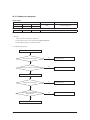
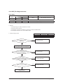
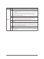
Outdoor LED Display Error and Check Method (18K/24K/30K)
LED PATTERN
DESCRIPTION
YEL
GRN
RED
ل
ل
ل
Power off/VDD NG
ل
ل
ሱ
IPM OVER CURRENT (O.C)
ل
ل
م
ل
م
م
ABNORMAL SERIAL COMMUNICATION
(DISPLAY BOARD : INDOOR ͑׳OUTDOOR)
ل
ሱ
م
NORMAL OPERATION
ل
ሱ
ل
COMP STARTING ERROR
ل
م
ሱ
ሱ
ل
ሱ
OUT-TH(OUTDOOR TEMPERATURE) SENSOR ERROR
ሱ
ل
م
DIS-TH(DISCHARGE TEMPERATURE) OVER ERROR
ሱ
ሱ
ل
DIS-TH(DISCHARGE TEMPERATURE)SENSOR ERROR
ሱ
ሱ
م
ሱ
م
ل
ሱ
م
ሱ
COIL TEMP SENSOR SENSOR ERROR (DUAL/SINGLE)
ሱ
م
م
1 MIN TIME OUT COMM
(MAIN MICOM INV MICOM)
ل
م
ل
EEPROM DATA ERROR
م
ل
ل
FAN ERROR
م
ل
ሱ
OTP ERROR
م
ل
م
COMP ROTATION ERROR
م
ሱ
ل
OPERATION CONDITION SECESSION (DUAL ONLY)
م
ሱ
ሱ
DC-LINK VOLTAGE SENSOR ERROR/
INPUT VOLTAGE SENSOR ERROR
م
ሱ
م
I-TRIP ERROR/PFC OVER CURRENT
م
م
ل
GAS LEAK/EEV OR VALVE ERROR-SELF DIAGNOSIS/HIGH PRESSION BLOCK
م
م
ሱ
AC LINE ZERO CROSS SIGNAL OUT
م
م
م
POWER ON RESET (1SEC)
ሱ
ل
ل
CAPACITY MISS MATCH
ل
ሱ
ሱ
TEST OPERATION COOLING MODE
ሱ
ሱ
ሱ
TEST OPERATION HEATIN G MODE
DC-LINK VOLTAGE UNDER/OVER ERROR
PFC OVERLOAD/H/W/ DC LINK OVER
CURRENT SENSOR ERROR
HEAT SINK SENSOR/INPUT CURRENT SENSOR ERROR
COMP V LIMIT ERROR
HEAT SINK OVER HEAT
͑مLED ON, ͑لLED OFF, ሱ͑LED BLINKING
3-4
Samsung Electronics
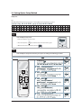
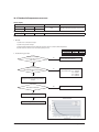
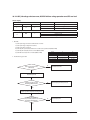
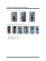
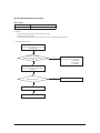
3-3 Setting Option Setup Method
e) Option No. :
Note :
SEG1, SEG7, SEG13, SEG19 need not to be pressed in, so in fact the Option No. we should press in is as below.
SEG1 SEG2 SEG3 SEG4 SEG5 SEG6 SEG7 SEG8 SEG9 SEG10 SEG11 SEG12 SEG13 SEG14 SEG15 SEG16 SEG17 SEG18 SEG19 SEG20 SEG21 SEG22 SEG23 SEG24
SEG25 SEG26 SEG27 SEG28 SEG29 SEG30 SEG31 SEG32 SEG33 SEG34 SEG35 SEG36 SEG37 SEG38 SEG39 SEG40 SEG41 SEG42 SEG43 SEG44 SEG45 SEG46 SEG47 SEG48
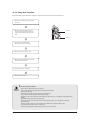
Step 1
Enter the Option Setup mode.
1. Tack out the batteries of remote control.
2. Press the temperature
button simultaneously and insert the battery again.
3. Make sure the remote control display shown as
.
Step 2
Enter the Options Setup mode and select your options asscording to the following procedure.
Samsung Electronics
3-5
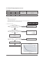
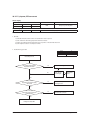
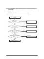
Step 3
Upon completion of the selection, check you made right selections.
Press the Mode
Selection key to set the display part and check the display part.
→ The display part shows like below when each time you press Mode button.
Step 4
Pressing the ON/OFF button (
).
When pressing the operation ON/OFF key with the direction of remote control for unit, the sound ’ Ding’’ or ’ Diriring’’ is heard
and the OPERATION ICON(
) lamp of the display is flickering at the same time, then the input of option is completed.
(If the deriving sound isn’t heard, try again pressing the ON/OFF button.)
3-6
Samsung Electronics
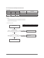
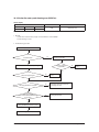
Step 5
Enter the Options Setup mode and select your options asscording to the following procedure.
Step 1 (Enter the Option Setup mode) is executed.
(Seg25 ~ 48 for setting remote control Setup)
Push the
Mode button to set the display panerl to 2.
Every time you push the
...
Push the
Samsung Electronics
...
repeatedly.
Mode button to set the display panerl to 1.
Every time you push the
button, the display panel reads
button, the display panel reads
repeatedly.
3-7
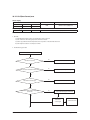
Step 6
Upon completion of the selection, check you made right selections.
Press the Mode
Selection key to set the display part and check the display part.
→The display part shows like below when each time you press Mode button.
Pressing the ON/OFF button (
Step 7
).
When pressing the operation ON/OFF key with the direction of remote control for unit, the sound ’ Ding’’ or ’ring’’
and the OPERATION ICON(
) lamp of the display is flickering at the same time, then the input of option is completed.
(If the deriving sound isn’t heard, try again pressing the ON/OFF button.)
Step 8
Unit operation test-run.
First : Remove the battery from the remote control.
Second : Re-insert the battery into the remote control.
Third : Press ON/OFF key with the direction of remote control for set.
■Error mode
1. If all lamps of indoor unit are flickering, Plug out, plug in power plug again and press ON/OFF key to retry.
2. If the unit is not working properly or all lamps are continuously flickering after setting the option code, the correct option code is
set up for its model.
□Option Items
0RGHO
6(*
6(*
6(*
6(*
6(*
6(*
6(*
$5+6)6-:.&9
$5+6)6-:.&9
$5+6)6-:.&9
$5+6)6-:.&9
$
$$
$
$'
&
3-8
6(* 6(* 6(* 6(* 6(*
)
$
%
)
)
(
Samsung Electronics
Uponc ompletion of the sele ction, check y ou maderight sele ction s.
Step 6
Press the Mode
Selection key to s
et t he display part a ndch eck the di splay part.
→The disp lay part sh ows li ke bel ow when each t ime you press M odebutton.
Pressing the ON/OFF butt on( ) .
Step 7
Whenpr essing the oper at io n ON/OFF key with the direc ti on of r emote co ntrol for u
and the OPERATION IC ON( ) la mp of the di splay is f
(If
the deriving sound is n’t
heard, try
li ckering at the s
ame time,
nit , t he so und ’ ’Drd ing’’ or
then the in put of option is co
mpleted.
again pr essing the ON/OFF butt on. )
Unit operation t est-run .
Step 8
Firs t: Remove the battery fr om the r emote c ontrol.
Second : Re -inse rt the battery in to the r emote c ontrol.
Third : Pr ess ON/OFF key with the di rec tion of r emote c ontr ol f or set .
■ Er r or mode
1. If all
2. If
la mps of i ndoor u ni t are fl ick eri ng, Pl ug out, pl ugin power pl ug agai n and pre ss ON/OFF key to retry.
the unit is not work ing pr operly or all lamps are c ontinuously flickering
set upfor its mo
aft er setting
orrect
the option
option cc ode
ode,is
del.
□ Option It ems
0RGHO
6(*
6(*
6(*
6(*
6(*
6(*
6(*
6(*
6(*
6(*
6(*
6(*
$5+6)6-:.&9
$5+6)6-:.&9
$5+6)6-:.&9
$5+6)6-:.&9
$
$$
$
$'
&
)
$
%
)
)
(
3- 8
Samsung Ele ctr onic s
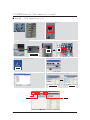
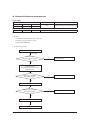
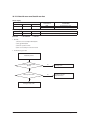
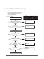
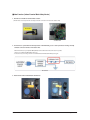
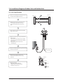
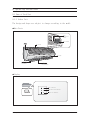
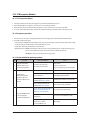
3-4 EEPROM Download (485 communication model)
Ƶ Method#1 : Using Communication line
1) Power off
2) Take off the side cover
3) Connect PC-Download Jig-PBA
F1,F2
(2pin)
F1,F2
(2pin)
RS 232 to 485
Converter
4) Execute the Inverter Download program
5) Select COM Port and connect
4) CLICK
7) Click the Start button and reset the power
6) Open the file (*.src)
Reset
power
Waiting down load
Download
6) CLICK
7) CLICK
Samsung Electronics
5) CLICK
3-9
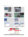
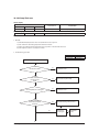
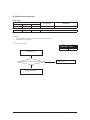
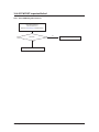
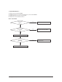
Ƶ Method#2 : Using Serial line
1) Power off
2) Take off the Cabinet : Check the LED off
3) Connect PC-Download Jig-PBA
Download connector
(10pin)
RS 232 to Serial
Download Converter
Download connector
(10pin,Black)
1)DB41-01010A : CN201
2)DB41-01129A : CN201
3)DB41-01023A : CN512
4)DB41-01081B : CN37
PIN# 1:RXD, 2:TXD, 9:GND, 10:VCC
Download connector
(20pin, Black)
1)DB41-01227A : CN201
2)DB41-01228A : CN201
PIN# 1:RXD, 2:TXD, 9:GND, 10:VCC
4) Execute the Inverter Download program
5) Select COM Port and connect
4) CLICK
6) Open the file(*.src)
7) Click the Start button
Waiting down load
Download
6) CLICK
7) CLICK
3-10
5) CLICK
Samsung Electronics
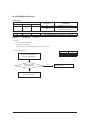
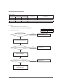
4. Disassembly and Reassembly
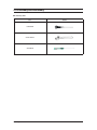
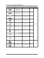
Q Necessary Tools
Item
Remark
+SCREW DRIVER
MONKEY SPANNER
- SCREW DRIVER
Samsung Electronics
4-1
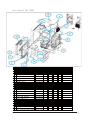
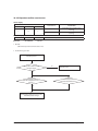
4-1. Indoor Unit
No
Parts
Procedure
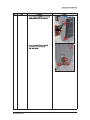
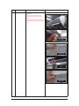
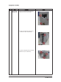
1
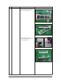
PANEL-FRONT
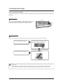
1) Stop the driving of air conditioner and shut off
main power supply.
Remark
2) Detach FILTER PRE from the PANEL FRONT.
3) Cover Panel is assembled on bottom of indoor
unit as shown in the figure.
Remove the Cap Screw as shown on the right
side and then remove the screw and separate
the Cover Panel.
4-2
Samsung Electronics
No
Parts
Procedure
Remark
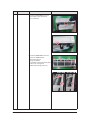
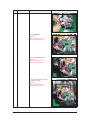
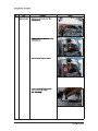
4) Cover Panel is fixed to body by Hook in center
area and side area.
Center area
Side area
Side area
HOOK
9/12K
18/24/30K
5) Separate the hook after pushing both end of
Cover Panel as shown in the figure.
(Watch out for the damage of the hook)
6) Raise front part upward obliquely as shown in
the figure and then remove the hooks.
Samsung Electronics
4-3
No
Parts
Procedure
Remark
Caution:
Assembly of Cover Panel after service end.
- Reassembly is in the reverse order of the
removal.
- Piping and drain hose must be careful not to
damage and Progress must be done with both
hands.
Hook (Side)
Hook (Center)
Screw
Cap Screw
4-4
Samsung Electronics
No
Parts
Procedure
Remark
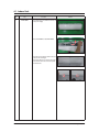
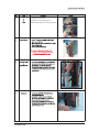
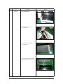
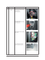
7) To detach the PANEL-FRONT from the main
frame, unfasten 2 screws at the bottom.
(use + Screw Driver)
8) To detach the COVER-PANEL from the main
frame, loosen 4 HOOK Structures.
When separate the hook :
Use the (-) screw Driver.
(-)Screw Driver Insert the hook and then pull the
hook as shown on the right side.
(Watch out for the damage of the hook)
Samsung Electronics
4-5
No
Parts
Procedure
Remark
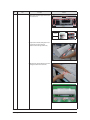
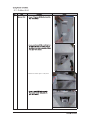
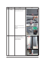
9) Remove the Panel Frame from the Main
Frame as shown on the right side.
10) Remove the WIFI KIT connector.
WIFI KIT connector is located of Panel Front.
(For model with WIFI KIT)
4-6
Samsung Electronics
No
Parts
Procedure
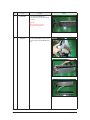
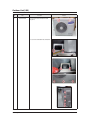
2
CONTORL IN
5) Loosen Stepping MOTOR Wire / BLADE Wire.
Remark
6) Loosen MOTOR Wire.
Caution:
When you separate the connector,
pull pressing the locking button.
7) Loosen the terminal block wires.
Caution:
When you separate the connector,
pull pressing the locking button.
8) Loosen the Thermistor wire connector,
Display wire connector.
Caution:
When you separate the connector,
pull pressing the locking button.
Samsung Electronics
4-7
No
Parts
5
EVAPORATOR
Procedure
Remark
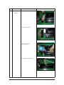
9) Take off the CASE-CONTROL from
the main frame after loosen the remaining
connector.
Caution:
When you separate the connector,
pull pressing the locking button.
3
4-8
TRAY DRAIN
1) To detach TRAY-DRAIN from the main frame,
pull the bottom of the TRAY-DRAIN towards
you.
Samsung Electronics
No
Parts
4
Evaporator
Procedure
Remark
1) Detach the HOLDER PIPE.
2) Unfasten the screw at the left side.
(use + Screw Driver)
3) Unfasten the screw at the right side.
(use + Screw Driver)
4) To detach Evaporator from the main frame,
pull the bottom of the Evaporator towards
you.
Samsung Electronics
4-9
No
Parts
5
FAN MOTOR
&
CROSS FAN
Procedure
Remark
1) Unfasten the screw. (use + Screw Driver)
2) Detach the FAN Motor case.
3) Unfasten the screw a little.
(use + Screw Driver)
4) Pull the CROSS-FAN to the left side.
4-10
Samsung Electronics
No
Parts
6
Assy SPI Lamp
Procedure
Remark
1) Remove the Assy SPI Lamp from the Back
Body as shown on the right side.
Caution:
- Confirm Seal of backside necessarily after
replace of Assy SPI Lamp.
- Seal should be close adhesion to SPI Lamp.
- Measure as shown on the right side since
replace.
(If the seal is not close adhesion perfectly :
Defectiveness can happen)
Samsung Electronics
4-11
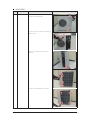
4 2 Outdoor Unit
3) Detach the Cabinet Upper li
e the picture.
5) Loosen 2 screw(CCW) on the right side of
Cabinet Front. (Use Screw Driver)
6) Loosen 2 screw(CCW) on the left side of
Cabinet Front. (Use Screw Driver)
7) Loosen 3 screw(CCW) on the front side of
Cabinet Front. (Use Screw Driver)
4-2-2
8
3
9
4-2-4
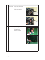
1) Release Nut at Fan Boss
2) Release 3 screws st Motor Brac et.
3) Detach Motor Wire from the Assy Control Out.
1
4-2-5
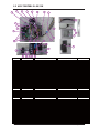
Outdoor Unit(18K)
No
Parts
1
Common Work
Procedure
Remark
1) Loosen each screws and detach the Cabi
Top Cover.
2) Loosen screws of the Cabi Front and detach it.
Samsung Electronics
4-17
No
Parts
Procedure
Remark
3) Loosen the 4 screws and detach the condbar.
4) Loosen fixing screws from the Cabi Front Lh
and detach it.
5) Loosen fixing screws from the Cabi Side Rh
and detach it.
4-18
Samsung Electronics
No
Parts
2
Fan
&
Motor
Procedure
Remark
1) Detach the Nut Flange like the picture on
the right side.(Turn clockwise because the
screw is left-handed.)
(Use Monkey Spanner.)
2) Detach the Fan Propeller.
3) Loosen 4 fixing screws to detach the Motor.
(Use Monkey Spanner.)
4) Disconnect the wire between Ass’y Control
Out and Motor.
5) Loosen 2 fixing bolts and detach the
Bracket Motor.(Use Monkey Spanner
Samsung Electronics
4-19
No
Parts
Procedure
3
Ass’y
Control Out
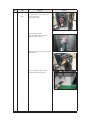
1) To remove the Cover control box : Pull the motor
wire is allow sufficient space as shown on the
right side and then remove the screw.
Remark
2) Detach several connectors from the Ass’y
Control Out.
3) Detach several connectors from the PCB of Ass’y
Control Out.
4
4-20
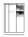
Heat Exchanger
1) Release the refrigerant at first.
2) Loosen fixing screw on both sides.
3) Disassemble the pipes in both inlet and
outlet with welding torch.
4) Detach the Heat Exchanger.
Samsung Electronics
No
Parts
Procedure
5
Compressor
1) Loosen the fixing nut and detach the
Compressor Lead Wire. (Use Monkey Spanner.)
Remark
2) Loosen the bolts at the bottom of Compressor
like the picture on the right side.
(Use Monkey Spanner.)
Samsung Electronics
4-21
$5+6)6+:.;&9
1R
3DUWV
&RPPRQ
:RUN
3URFHGXUH
5HPDUN
/RRVHQ IL[LQJVFUHZVRIWKH&DEL)URQW5K
DQG GHWDFKWKH&DEL)URQW5K
/RRVHQ HDFK IL[LQJVFUHZVDQG GHWDFKWKH
&DEL7RS &RYHU
/RRVHQ IL[LQJVFUHZVIURP WKH&DEL
)URQW5K
/RRVHQ IL[LQJVFUHZVIURP FRQG EDU
6DPVXQJ (OHFWURQLFV
No
Parts
Procedure
Remark
5) Loosen the 4 screws and detach the condbar(Right).
6) Loosen the fixing screws and detach the
Cabi Back Lf.
7) Loosen 13 fixing screws of the Cabi Front Lf
and detach it.
Samsung Electronics
3-17
No
Parts
Fan
&
Motor
Procedure
Remark
1) Detach the Nut Flange like the picture on
the right side.(Turn clockwise because the
screw is left-handed.)
(Use Monkey Spanner.)
2) Detach the Fan Propeller.
3) Loosen 4 fixing screws to detach the
Motor.(Use Monkey Spanner.)
4) Disconnect the wire between Ass’y Control
Out and Motor.
5) Loosen 2 fixing bolts and detach the
Bracket Motor.(Use Monkey Spanner.)
3-18
Samsung Electronics
No
Parts
3
Ass’y Control Out
1) Detach several connectors from the
Ass’y Control Out.
2) Detach several connectors from the PCB
of Ass’y Control Out.
3) Pull up the Ass’y Control Out.
4
Heat Exchanger
1) Release the refrigerant at first.
2) Loosen fixing screw on both sides.
3) Disassemble the pipes in both inlet and
outlet with welding torch.
4) Detach the Heat Exchanger.
Samsung Electronics
Procedure
Remark
3-19
No
Parts
5
Compressor
Procedure
Remark
1)Loosen the fixing nut and detach the
Compressor Lead Wire.
(Use Monkey Spanner.)
3) Loosen the 3 bolts at the bottom of
Compressor like the picture on the
right side.(Use Monkey Spanner.)
3-20
Samsung Electronics
5-2 ASSY CONTROL IN -9K/12K
1R
&2'(
'%(
5-2
'HVFULSWLRQ
$66<&21752/,1
6SHF
4
7<
'%&
$OXPLQXP6+((7
[[7$/6+((7
'%%
&$6(&21752/,1
&$6(&21752/,1
'%$
32:(5:,5(
7%PDLQSRZHU
'%$
($57+:,5(
($57+:,5(
'%$
7(50,1$/%/2&.
7(50,1$/%/2&.
'%)
6($/&877
39&%/$&.7:
'%$
6($/&21752/
$66</$%(/
)/2&.('%/$&.7:
$66</$%(/
'%$
'%$
&20081,&$7,21:,5(
7%PDLQ
'%$
)86(:,5(
SRZHUPDLQ99
'%'
$OXPLQXP6+((7
[[7$/6+((7
'%$
$66</$%(/
$66</$%(/
'%$
3/$7(&21752/,1
)
'%$
$66</$%(/
$66</$%(/
'%$
6&5(:
0/=3&:+76:5&+$
'%$
3/$7(
3/$7(
6&5(:
7+0/=3&:+76:5&+$
6&5(:
0/=3&:+76:5&+$
'%$
+2/'(5:,5(&/$03
+2/'(5:,5(&/$03
'%&
0$,13%$
67'
'%$
32:(53%$
67':
'%$
6($/&$6(/()7
6($/&$6(/()7
'%$
$66<&211(&725:,5('&
SRZHUPDLQ99
'%$
$66<7+(50,6725,1
VHQVRUURRP,HYDS
'%$
$66<&211(&725:,5('&
)-0
6&5(:
6&5(:
'%$
$66<&211(&725:,5('&
%/'&
'%$
$66<&211(&725:,5('&
',63/$<02725
'%%
'%$
$66<&211(&725:,5('&
',63/$<02725
$66<&211(&725:,5('&
67(302725
'%$
$66<&211(&725:,5('&
63,
'%$
3/$7(&21752/83
3/$7(&21752/83
'%$
$66<3/$7(&21752/
5,*+7
'%$
$66<&211(&725:,5('&
6WHSPDLQ/HIW
'%$
$66<&211(&725:,5('&
:,),
Samsung Electronics
5-2 ASSY CONTROL IN-18K
B
0Q
%1&'
&GUETKRVKQP
#55;%10641.+0
&$(
$66<6&5(:7$33,1*
΄ΡΖΔ
͘΅Ί
ͳͲ͞΅ͲͺͿ
ΡΠΨΖΣ͞ΞΒΚΟ͙ͤ͢͡·͑ͪ͢·͚
ͣ
'%$
$66<&211(&725:,5('&
'%%
$66<&$6(&21752/,1
'%$
$66<&211(&725:,5('&
'%$
/$%(/%$5&2'(
'%$
$66<3&%0$,1,1
'%$
$66<02'8/(
'%$
$66<&211(&725:,5(32:(5
'%$
$66<7+(50,6725,1
'%$
&$6(&21752/,1
'%$
6833257&21752/
'%$
3/$7(&21752//()7
'%$
6($/&21752/$
'%&
6($/&877
'%&
6+((7&21752/
'%'
10x10xT0.07,AL SHEET
4
6+((7&21752/
'%$
22x22xT0.07,AL SHEET
1
7(50,1$/%/2&.
'%$
TERMINAL BLOCK
1
3/$7(&21752/68%
'%$
'%$
'%$
$66<&211(&725:,5(&200
'%$
$66<&211(&725:,5(($57+
'%$
$66<6&5(:7$33,1*
6&5(:7$33,1*
6&5(:63(&,$/
'%$
+2/'(5:,5(
'%$
$66<&211(&725:,5(
'%$
F-05
Step-main(up)
LABEL BAR CODE
΄΅͵ͥ
11W
ΞΒΚΟ͞ΡΠΨΖΣ͙΄;΄͑ͺͿ͚
sensor 1room,2evap
F-05
1
case sub
1
PLATE CONTROL-LEFT
1
1
FLOCKED 52*65*T1 BLACK
0.052m
PVC 52*30*T1 BLACK
1
PLATE CONTROL-SUB
$66<&211(&725:,5('&6,*1$/power-main(12V 5V)
$66<&211(&725:,5(32:(5
1
T/B-main(power)
1
T/B-main(485)
1
ASSY CONNECTOR WIRE-EARTH
1
M3,L25,ZPC(WHT),SWRCH18A
1
M4,L12,ZPC(WHT),SWRCH18A
TH,M4,L10,ZPC(WHT),SWRCH18A
3
HOLDER-WIRE
1
FJM
1
$66</$%(/&$87,21
'%$
ASSY-LABEL CAUTION
1
$66</$%(/&$87,21
'%$
ASSY-LABEL CAUTION
6($/&$6(/()7
1
SEAL CASE-LEFT
3
'%$
$66<&211(&725:,5(
'%$
FJM
$66<&211(&725:,5(
'%$
LEFT-RIGHT
0
$66<3/$7(&21752/
'%$
ASSY PLATE CONTROL
3/$7(&21752/83
1
'%$
'%%
5-2
PLATE CONTROL-UP
$66<&211(&725:,5('&
BLDC MOTOR WIRE
$66<&211(&725:,5(',63/$< DISPLAY WIRE
Samsung Electronics
5-2 ASSY CONTROL IN-24K
B
0Q
%1&'
&GUETKRVKQP
#55;%10641.+0
&$(
$66<6&5(:7$33,1*
΄ΡΖΔ
͘΅Ί
ͳͲ͞΅ͲͺͿ
ΡΠΨΖΣ͞ΞΒΚΟ͙ͤ͢͡·͑ͪ͢·͚
ͣ
'%$
$66<&211(&725:,5('&
'%%
$66<&$6(&21752/,1
'%$
$66<&211(&725:,5('&
'%$
/$%(/%$5&2'(
'%$
$66<3&%0$,1,1
'%$
$66<02'8/(
'%$
$66<&211(&725:,5(32:(5
'%$
$66<7+(50,6725,1
'%$
&$6(&21752/,1
'%$
6833257&21752/
'%$
3/$7(&21752//()7
'%$
6($/&21752/$
'%&
6($/&877
'%&
6+((7&21752/
'%'
10x10xT0.07,AL SHEET
4
6+((7&21752/
'%$
22x22xT0.07,AL SHEET
1
7(50,1$/%/2&.
'%$
TERMINAL BLOCK
1
3/$7(&21752/68%
'%$
'%$
'%$
$66<&211(&725:,5(&200
'%$
$66<&211(&725:,5(($57+
'%$
$66<6&5(:7$33,1*
6&5(:7$33,1*
6&5(:63(&,$/
'%$
+2/'(5:,5(
'%$
$66<&211(&725:,5(
'%$
F-05
Step-main(up)
LABEL BAR CODE
΄΅͵ͥ
11W
ΞΒΚΟ͞ΡΠΨΖΣ͙΄;΄͑ͺͿ͚
sensor 1room,2evap
F-05
1
case sub
1
PLATE CONTROL-LEFT
1
1
FLOCKED 52*65*T1 BLACK
0.052m
PVC 52*30*T1 BLACK
1
PLATE CONTROL-SUB
$66<&211(&725:,5('&6,*1$/power-main(12V 5V)
$66<&211(&725:,5(32:(5
1
T/B-main(power)
1
T/B-main(485)
1
ASSY CONNECTOR WIRE-EARTH
1
M3,L25,ZPC(WHT),SWRCH18A
1
M4,L12,ZPC(WHT),SWRCH18A
TH,M4,L10,ZPC(WHT),SWRCH18A
3
HOLDER-WIRE
1
FJM
1
$66</$%(/&$87,21
'%$
ASSY-LABEL CAUTION
1
$66</$%(/&$87,21
'%$
ASSY-LABEL CAUTION
6($/&$6(/()7
1
SEAL CASE-LEFT
3
'%$
$66<&211(&725:,5(
'%$
FJM
$66<&211(&725:,5(
'%$
LEFT-RIGHT
0
$66<3/$7(&21752/
'%$
ASSY PLATE CONTROL
3/$7(&21752/83
1
'%$
'%%
5-2
PLATE CONTROL-UP
$66<&211(&725:,5('&
BLDC MOTOR WIRE
$66<&211(&725:,5(',63/$< DISPLAY WIRE
Samsung Electronics
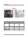
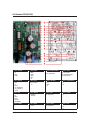
5-3 Assy Control Out (9K/12K)
No
NAME
CODE
TY
No
NAME
CODE
TY
1
GREASE-SILICON
0205-000178
0.002
8-12
ASSY CONNECTOR WIRE-COMM
DB93-14285A
1
2
SCREW-TAPPING
6002-000527
1
8-13
ASSY-SCREW TAPPING
DB97-02418A
4
3
SCREW-TAPPING
6002-000536
3
8-14
ASSY-LABEL CAUTION
DB98-33292A
1
4
CASE CONTROL
DB61-05883A
1
8-15
ASSY-LABEL CAUTION
DB98-33293A
1
5
HEAT SINK
DB62-11646A
1
8-16
ASSY-LABEL CAUTION
DB98-34030A
1
6
CABLE TIE
DB65-10088D
3
9
ASSY COVER CONTROL-UP
DB90-07729A
1
7
LABEL BAR CODE
DB68-02809A
1
9-1
PLATE CONTROL-UP
DB61-05821A
1
8
ASSY CASE CONTROL OUT
DB90-06308L
1
9-2
COVER CONTROL-OUT
DB63-03506A
1
8-1
SCREW-TAPPING
6002-000527
4
10
ASSY-SCREW MACHINE
DB91-00933A
4
8-2
SCREW-TAPPING
6002-000555
2
11
ASSY PCB SUB
DB92-02836A
1
8-3
SCREW-SPECIAL
6009-001001
4
12
ASSY MODULE
DB92-02862A
1
8-4
HOLDER-WIRE CLAMP
DB61-00250A
2
13
ASSY PCB MAIN
DB92-02866A
1
8-5
SUPPORT-PCB
DB61-04398A
2
14
ASSY CONNECTOR WIRE
DB93-09493C
1
8-6
PLATE CONTROL
DB61-05897A
1
15
ASSY CONNECTOR WIRE
DB93-09497E
1
8-7
TERMINAL BLOCK
DB65-00274A
1
16
ASSY CONNECTOR WIRE-POWER
DB93-14275A
1
8-8
TERMINAL BLOCK
DB65-00298B
1
17
ASSY CONNECTOR WIRE-DC SIGNAL
DB93-14276A
1
8-9
LABEL CAUTION
DB68-03146A
1
18
ASSY CONNECTOR WIRE-DC SIGNAL
DB93-14277A
1
19
ASSY CONNECTOR WIRE-DC SIGNAL
DB93-14278A
1
8-10
ASSY CONNECTOR WIRE
DB93-09495
1
8-11
ASSY CONNECTOR WIRE-EARTH WIRE
DB93-12121A
1
5-4
Samsung Electronics
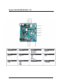
$VV\&RQWURO2XW .
uhtl
u
W
X
Y
Z
[
\
]
^
_
$66<&21752/287
*5($6(6,/,&21
6&5(:7$33,1*
6&5(:7$33,1*
&$6(&21752/287
&$6(&21752/833(5
6833257+($76,1.
+($76,1.
&$%/(7,(
jhislG{p l
jvkl
'%
'%$
'%$
'%$
'%$
'%%
'%&
'%$
`
/$%(/%$5&2'(
XW
$66<&$6(&21752/287
'%/
$66<&$6(&21752/287
'%1
$66<&$6(&21752/287
'%3
$66<6&5(:0$&+,1(
'%$
$66<3&%68%
'%$
$66<&211(&725:,5(:$<&2'%&
$66<3&%0$,1
'%.
$66<&211(&725:,5(
'%$
$66<&211(&725:,5(
'%(
$66<&211(&725:,5(
'%$
XX
XY
XZ
X[
X\
X]
X^
6DPVXQJ(OHFWURQLFV
xN
7
8
X
X
ylthyr
6
lh
lh
lh
lh
lh
lh
lh
lh
lh
lh
lh
lh
lh
lh
lh
lh
lh
lh
lh
lh
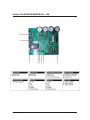
$VV\&RQWURO2XW .
1R
1$0(
$66<&21752/287
*5($6(6,/,&21
6&5(:0$&+,1(
6&5(:7$33,1*
6&5(:7$33,1*
6&5(:7$33,1*
6&5(:7$37<3(
6&5(:63(&,$/
$&5($&725
&$6(,19(57(53+$6(
+($76,1.
$66<6&5(:0$&+,1(
$66<6&5(:0$&+,1(
$66<&21752/287
$66<&21752/287
$66<3&%0$,1,19(57(5
&2'(
'%
'%$
'%$
'%$
'%$
'%$
'%'
'%*
'%)
'%'
'%(
$66<&211(&725:,5(&2000$'%$
4
W\
XQLW
*
+
5(0$5.
.*
3&
3&
3&
3&
3&
3&
3&
3&
3&
3&
3&
3&
3&
3&
3&
3&
3&
6DPVXQJ(OHFWURQLFV
(OHFWULFDO3DUWV/LVW
,1'2250$,13&%'%&
3DUWV&RGH
'HVLJQ/RF
3DUWV'HVFULSWLRQ
4XDQWLW\
'%$
'%$
'%$
'%$
'%$
62/'(5:,5(
62/'(5:,5()/8;
)/8;
4
9$
;&
;&
%=
&1
&1
&1
&1
&1
&1
&1
&1
&1
&1
&1
&1
&1
&1
&1
)7
9$
/$%(/%$5&2'(
4
37&
)
62/'(5&5($0
'
&'
&'
&'
4
4
4
,&
,&
3&
3&
3&
,&
,&
,&
,&
,&
5
5
5
5
5
5
5
5
5
5
5
5
5
5
5
5
5
5
$'+(6,9(6,/
62/'(5:,5(
62/'(5:,5()/8;
)/8;
7532:(5
9$5,6725
&),/0/($'33)
&),/0/($'33)
%8==(53,(=2
+($'(5%2$5'72&$%/(
+($'(5%2$5'72&$%/(
+($'(5%2$5'72&$%/(
+($'(5%2$5'72&$%/(
+($'(5%2$5'72&$%/(
&211(&725+($'(5
+($'(5%2$5'72&$%/(
+($'(5%2$5'72&$%/(
+($'(5%2$5'72&$%/(
+($'(5%2$5'72&$%/(
+($'(5%2$5'72&$%/(
+($'(5%2$5'72&$%/(
+($'(5%2$5'72&$%/(
+($'(5%2$5'72&$%/(
+($'(5%2$5'72&$%/(
&2,/&+2.(
&$3
/$%(/%$5&2'(
$66<3&%$872
7560$//6,*1$/
7+(50,672537&
)86((7&
$66<3&%60'
62/'(5&5($0
',2'(5(&7,),(5
',2'(796
',2'(796
',2'(796
7560$//6,*1$/
75',*,7$/
75',*,7$/
75$55$<
75$55$<
3+272&283/(5
3+272&283/(5
3+272&283/(5
,&&026/2*,&
,&%8675$16&(,9(5
,&92/7$*(&203
,&92/'(7(&725
,&326,),;('5(*
5&+,3
5&+,3
5&+,3
5&+,3
5&+,3
5&+,3
5&+,3
5&+,3
5&+,3
5&+,3
5&+,3
5&+,3
5&+,3
5&+,3
5&+,3
5&+,3
5&+,3
5&+,3
6DPVXQJ(OHFWURQLFV
,1'2250$,13&%'%&
6DPVXQJ(OHFWURQLFV
5
5
5
5
5
5
5
5
5
5
5
5
5
5
5
5
5
5
5
5
5
5
5
5
5
5
5
5
5
5
5
5
5
5
5
5
5
5
5
5
5
5
5
5
5
5
5
5
5
5
5
5
5
5
5
5
5
5
5
5
5
5
5
5
5
5
5
5
5
5
5&+,3
5&+,3
5&+,3
5&+,3
5&+,3
5&+,3
5&+,3
5&+,3
5&+,3
5&+,3
5&+,3
5&+,3
5&+,3
5&+,3
5&+,3
5&+,3
5&+,3
5&+,3
5&+,3
5&+,3
5&+,3
5&+,3
5&+,3
5&+,3
5&+,3
5&+,3
5&+,3
5&+,3
5&+,3
5&+,3
5&+,3
5&+,3
5&+,3
5&+,3
5&+,3
5&+,3
5&+,3
5&+,3
5&+,3
5&+,3
5&+,3
5&+,3
5&+,3
5&+,3
5&+,3
5&+,3
5&+,3
5&+,3
5&+,3
5&+,3
5&+,3
5&+,3
5&+,3
5&+,3
5&+,3
5&+,3
5&+,3
5&+,3
5&+,3
5&+,3
5&+,3
5&+,3
5&+,3
5&+,3
5&+,3
5&+,3
5&+,3
5&+,3
5&+,3
5&+,3
,1'2250$,13&%'%&
'%$
'%%
'%$
6DPVXQJ(OHFWURQLFV
5
5
5
5
5
5
5
5
5
5
5
5
&
&
&
&
&
&
&
&
&
&
&
&
&
&
&
&
&
&
&
&
&
&
&
&
&
&
&
&
&
&
&
&
&
&
&
&
&
&
&
&
&
&
&
&
&
&
&
&
&
;
3&%0$,1
$66</$%(/0,&20
5&+,3
5&+,3
5&+,3
5&+,3
5&+,3
5&+,3
5&+,3
5&+,3
5&+,3
5&+,3
5&+,3
5&+,3
&&(5&+,3
&&(5&+,3
&&(5&+,3
&&(5&+,3
&&(5&+,3
&&(5&+,3
&&(5&+,3
&&(5&+,3
&&(5&+,3
&&(5&+,3
&&(5&+,3
&&(5&+,3
&&(5&+,3
&&(5&+,3
&&(5&+,3
&&(5&+,3
&&(5&+,3
&&(5&+,3
&&(5&+,3
&&(5&+,3
&&(5&+,3
&&(5&+,3
&&(5&+,3
&&(5&+,3
&&(5&+,3
&&(5&+,3
&&(5&+,3
&&(5&+,3
&&(5&+,3
&&(5&+,3
&&(5&+,3
&&(5&+,3
&&(5&+,3
&&(5&+,3
&&(5&+,3
&&(5&+,3
&&(5&+,3
&&(5&+,3
&&(5&+,3
&&(5&+,3
&&(5&+,3
&&(5&+,3
&&(5&+,3
&&(5&+,3
&&(5&+,3
&&(5&+,3
&$/60'
&$/60'
&$/60'
5(621$725&(5$0,&
3&%0$,1
$66<0,&20
,&0,&52&21752//(5
$66</$%(/0,&20
*/%003%*41-":1#"%#
4&(
3DUWV&RGH 'HVLJQ/RF
&1
&1
&1
&1
&1
'%$
'%$
'%$
4XDQWLW\
3DUWV'HVFULSWLRQ
+($'(5%2$5'72&$%/(
+($'(5%2$5'72&$%/(
+($'(5%2$5'72&$%/(
+($'(5%2$5'72&$%/(
+($'(5%2$5'72&$%/(
/('',63/$<
='
4
$66<3&%$872
/('
/('
$66<3&%60'
',2'(=(1(5
75',*,7$/
,&
,&/(''5,9(5
5&+,3
5&+,3
5&+,3
5&+,3
5&+,3
5&+,3
&&(5&+,3
&&(5&+,3
&&(5&+,3
&&(5&+,3
&$/60'
3&%',63/$<
,&
/('
/('
5
5
5
5
5
5
&
&
&
&
&
'%$ 3&%',63/$<
6SHF
%2;35PP$1*/(61:+7
%2;35PP675$,*+761:+7
%2;35PP675$,*+761:+7
%2;35PP675$,*+761:+7
%2;3500675$,*+761%/.
:+,7(75$<[[[75$<
[[[
%(77(5%(67$'%$
5281'%/8(PP[PP
5281'%/8(PP[PP
%(77(5%(67$'%$
%=;&99P:62773
.5&6131P:..RKP62773
67/('6623[PP
P$733/$67,&9
P:,&/(''5,9(5
RKP:73
.RKP:73
.RKP:73
.RKP:73
.RKP:73
.RKP:73
Q)9;573
Q)9;573
Q)9;573
Q)9;573
X)973[PP
)5/D\HU%(77(5%(672]
4BNTVOH&MFDUSPOJDT
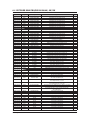
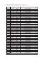
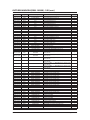
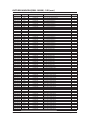
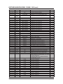
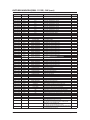
6-4 OUTDOOR MAIN PBA(DB92-02866A) - 9K/12K
Parts Code
Design Loc
Description
Spec.
TY
0401-001099
0401-001099
0401-001099
0401-001099
0401-001099
0401-001099
0401-001099
0401-001099
0401-001099
0401-001099
0401-001099
0401-001099
0401-001099
0401-001099
0401-001099
0401-001099
0402-001795
0403-001499
0403-001499
0404-001020
0404-001020
0406-001204
0406-001204
0406-001204
0501-000465
0504-001008
0504-001008
0504-001008
0504-001008
0504-001044
0504-001080
0506-000175
0506-000175
0506-000175
0601-002423
0601-002955
0601-002956
0601-002956
0604-001172
0604-001172
0604-001172
D020
D021
D030
D152
D153
D454
D500
D501
D502
D503
D504
D505
D507
D508
D904
D905
D903
ZD401
ZD420
D491
D492
TD301
TD302
TD303
Q551
Q351
Q352
Q901
Q903
Q151
Q902
IC061
IC701
IC702
LED801
LED803
LED551
LED802
PC151
PC351
PC352
DIODE-SWITCHING
DIODE-SWITCHING
DIODE-SWITCHING
DIODE-SWITCHING
DIODE-SWITCHING
DIODE-SWITCHING
DIODE-SWITCHING
DIODE-SWITCHING
DIODE-SWITCHING
DIODE-SWITCHING
DIODE-SWITCHING
DIODE-SWITCHING
DIODE-SWITCHING
DIODE-SWITCHING
DIODE-SWITCHING
DIODE-SWITCHING
DIODE-RECTIFIER
DIODE-ZENER
DIODE-ZENER
DIODE-SCHOTTKY
DIODE-SCHOTTKY
DIODE-TVS
DIODE-TVS
DIODE-TVS
TR-SMALL SIGNAL
TR-DIGITAL
TR-DIGITAL
TR-DIGITAL
TR-DIGITAL
TR-DIGITAL
TR-DIGITAL
TR-ARRAY
TR-ARRAY
TR-ARRAY
LED
LED
LED
LED
PHOTO-COUPLER
PHOTO-COUPLER
PHOTO-COUPLER
1
1
1
1
1
1
1
1
1
1
1
1
1
1
1
1
1
1
1
1
1
1
1
1
1
1
1
1
1
1
1
1
1
1
1
1
1
1
1
1
1
0801-000393
IC302
IC-CMOS LOGIC
1006-001325
IC301
IC-BUS TRANSCEIVER
1201-002946
IC451
IC-OP AMP
1203-002835
1203-002986
IC154
IC155
IC-POSI.FIXED REG.
IC-POSI.FIXED REG.
1203-004967
IC502
IC-VOL. DETECTOR
1404-001498
1405-000154
1405-000154
1405-001239
1405-001239
2007-000043
2007-000070
2007-000074
2007-000074
2007-000074
2007-000074
2007-000074
2007-000074
PTC020
VA002
VA003
VA001
VA401
R424
R309
R152
R210
R213
R233
R234
R401
THERMISTOR-PTC
VARISTOR
VARISTOR
VARISTOR
VARISTOR
R-CHIP
R-CHIP
R-CHIP
R-CHIP
R-CHIP
R-CHIP
R-CHIP
R-CHIP
1N4148WS,75V,150mA,SOD-323,TP
1N4148WS,75V,150mA,SOD-323,TP
1N4148WS,75V,150mA,SOD-323,TP
1N4148WS,75V,150mA,SOD-323,TP
1N4148WS,75V,150mA,SOD-323,TP
1N4148WS,75V,150mA,SOD-323,TP
1N4148WS,75V,150mA,SOD-323,TP
1N4148WS,75V,150mA,SOD-323,TP
1N4148WS,75V,150mA,SOD-323,TP
1N4148WS,75V,150mA,SOD-323,TP
1N4148WS,75V,150mA,SOD-323,TP
1N4148WS,75V,150mA,SOD-323,TP
1N4148WS,75V,150mA,SOD-323,TP
1N4148WS,75V,150mA,SOD-323,TP
1N4148WS,75V,150mA,SOD-323,TP
1N4148WS,75V,150mA,SOD-323,TP
US1M,1000V,1A,SMA,TP
MMSZ5252B,22.8/25.2V,500mW,SOD-123,TP
MMSZ5252B,22.8/25.2V,500mW,SOD-123,TP
BAT54C,30V,200mA,SOT-23,TP
BAT54C,30V,200mA,SOT-23,TP
SMB5.0CA,6.4/-/7.25V,600W,SMB
SMB5.0CA,6.4/-/7.25V,600W,SMB
SMB5.0CA,6.4/-/7.25V,600W,SMB
MMBT3904,NPN,350mW,SOT-23,TP,30-300
RN2427,PNP,200mW,2.2K/10Kohm,SOT-23,TP
RN2427,PNP,200mW,2.2K/10Kohm,SOT-23,TP
RN2427,PNP,200mW,2.2K/10Kohm,SOT-23,TP
RN2427,PNP,200mW,2.2K/10Kohm,SOT-23,TP
KRA226M,PNP,400MW,2.2K/10K,TO-92M,TP
KRC246S,NPN,200mW,2.2K/10Kohm,SOT-23,TP
2003,NPN,7,1W,SOP-16,ST,1000
2003,NPN,7,1W,SOP-16,ST,1000
2003,NPN,7,1W,SOP-16,ST,1000
SMD(REVERSE),RED,3.2x1.6mm,639nm,3.2x1.6x1.1mm
SMD(REVERSE),YEL,1.6x1.5mm,588nm,3.2x1.6x1.1mm
SMD(REVERSE),GRN,1.6x1.5mm,3.2x1.6x1.1mm
SMD(REVERSE),GRN,1.6x1.5mm,3.2x1.6x1.1mm
TR,150-300,200mW,SOP,TP
TR,150-300,200mW,SOP,TP
TR,150-300,200mW,SOP,TP
74HC86,OR GATE,SOP,14P,150MIL,QUAD,ST,-,2.0/6.0V,0.26V,40to+85C,180mW,4.2V,1uA,
ISL81487LIBZ,SO,8P,4.9x3.8 mm,SINGLE,ST,PLASTIC,5V,40to+85C,520mW,1,1,1.5/5.0V
TSSOP,TR,14P,5x4.4x1.2mm,100,5.5V,40to+85C,63dB,1,1nA,1nA,1.7mV
7805,3P,6.6x6.1mm,PLASTIC,4.8V/5.2V,1.3W,-40to+85,1A,TP
7812,3P,6.6x6.1mm,PLASTIC,11.5/12.5V,1.3,150C,1A,TP
KIA7042AT,TSM,3P,2.9x1.6mm,PLASTIC,4.2V,350mW,30to+75C,20mA,-,40ohm,25 ,290Vac,7A,TR
560V,460Vdc,4500A,17.5x7.5mm,BK,920V,600pF
560V,460Vdc,4500A,17.5x7.5mm,BK,920V,600pF
680V,560Vdc,6000A,17x7.3mm,BK,1120V,350pF
680V,560Vdc,6000A,17x7.3mm,BK,1120V,350pF
1Kohm,1 ,1/10W,TP,1608
0ohm,5 ,1/10W,TP,1608
100ohm,5 ,1/10W,TP,1608
100ohm,5 ,1/10W,TP,1608
100ohm,5 ,1/10W,TP,1608
100ohm,5 ,1/10W,TP,1608
100ohm,5 ,1/10W,TP,1608
100ohm,5 ,1/10W,TP,1608
Samsung Electronics
1
1
1
1
1
1
1
1
1
1
1
1
1
1
1
1
1
1
1
6-7
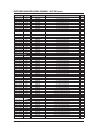
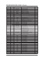
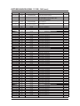
OUTDOOR MAIN PBA(DB92-02866A) - 9K/12K (cont.)
Parts Code
Design Loc
Description
Spec.
TY
2007-000074
2007-000074
2007-000074
2007-000074
2007-000074
2007-000074
2007-000074
2007-000074
2007-000074
2007-000074
2007-000074
2007-000076
2007-000076
2007-000076
2007-000076
2007-000076
2007-000076
2007-000076
2007-000076
2007-000076
2007-000076
2007-000078
2007-000078
2007-000078
2007-000078
2007-000078
2007-000078
2007-000078
2007-000078
2007-000078
2007-000078
2007-000078
2007-000078
2007-000078
2007-000078
2007-000078
2007-000078
2007-000078
2007-000078
2007-000080
2007-000082
2007-000084
2007-000084
2007-000084
2007-000084
2007-000084
2007-000084
2007-000084
2007-000084
2007-000084
2007-000084
2007-000084
2007-000084
2007-000084
2007-000084
2007-000084
2007-000084
2007-000084
2007-000084
2007-000084
2007-000084
2007-000084
2007-000084
2007-000084
R402
R403
R404
R405
R406
R407
R420
R422
R516
R519
R562
R153
R255
R256
R257
R258
R352
R353
R512
R567
R904
R303
R307
R308
R351
R354
R503
R504
R505
R508
R509
R515
R529
R530
R556
R557
R558
R560
R563
R522
R421
R211
R212
R214
R215
R216
R217
R218
R219
R220
R408
R501
R506
R507
R510
R511
R517
R518
R520
R521
R523
R524
R525
R526
R-CHIP
R-CHIP
R-CHIP
R-CHIP
R-CHIP
R-CHIP
R-CHIP
R-CHIP
R-CHIP
R-CHIP
R-CHIP
R-CHIP
R-CHIP
R-CHIP
R-CHIP
R-CHIP
R-CHIP
R-CHIP
R-CHIP
R-CHIP
R-CHIP
R-CHIP
R-CHIP
R-CHIP
R-CHIP
R-CHIP
R-CHIP
R-CHIP
R-CHIP
R-CHIP
R-CHIP
R-CHIP
R-CHIP
R-CHIP
R-CHIP
R-CHIP
R-CHIP
R-CHIP
R-CHIP
R-CHIP
R-CHIP
R-CHIP
R-CHIP
R-CHIP
R-CHIP
R-CHIP
R-CHIP
R-CHIP
R-CHIP
R-CHIP
R-CHIP
R-CHIP
R-CHIP
R-CHIP
R-CHIP
R-CHIP
R-CHIP
R-CHIP
R-CHIP
R-CHIP
R-CHIP
R-CHIP
R-CHIP
R-CHIP
100ohm,5 ,1/10W,TP,1608
100ohm,5 ,1/10W,TP,1608
100ohm,5 ,1/10W,TP,1608
100ohm,5 ,1/10W,TP,1608
100ohm,5 ,1/10W,TP,1608
100ohm,5 ,1/10W,TP,1608
100ohm,5 ,1/10W,TP,1608
100ohm,5 ,1/10W,TP,1608
100ohm,5 ,1/10W,TP,1608
100ohm,5 ,1/10W,TP,1608
100ohm,5 ,1/10W,TP,1608
330ohm,5 ,1/10W,TP,1608
330ohm,5 ,1/10W,TP,1608
330ohm,5 ,1/10W,TP,1608
330ohm,5 ,1/10W,TP,1608
330ohm,5 ,1/10W,TP,1608
330ohm,5 ,1/10W,TP,1608
330ohm,5 ,1/10W,TP,1608
330ohm,5 ,1/10W,TP,1608
330ohm,5 ,1/10W,TP,1608
330ohm,5 ,1/10W,TP,1608
1Kohm,5 ,1/10W,TP,1608
1Kohm,5 ,1/10W,TP,1608
1Kohm,5 ,1/10W,TP,1608
1Kohm,5 ,1/10W,TP,1608
1Kohm,5 ,1/10W,TP,1608
1Kohm,5 ,1/10W,TP,1608
1Kohm,5 ,1/10W,TP,1608
1Kohm,5 ,1/10W,TP,1608
1Kohm,5 ,1/10W,TP,1608
1Kohm,5 ,1/10W,TP,1608
1Kohm,5 ,1/10W,TP,1608
1Kohm,5 ,1/10W,TP,1608
1Kohm,5 ,1/10W,TP,1608
1Kohm,5 ,1/10W,TP,1608
1Kohm,5 ,1/10W,TP,1608
1Kohm,5 ,1/10W,TP,1608
1Kohm,5 ,1/10W,TP,1608
1Kohm,5 ,1/10W,TP,1608
2Kohm,5 ,1/10W,TP,1608
3.3Kohm,5 ,1/10W,TP,1608
4.7Kohm,5 ,1/10W,TP,1608
4.7Kohm,5 ,1/10W,TP,1608
4.7Kohm,5 ,1/10W,TP,1608
4.7Kohm,5 ,1/10W,TP,1608
4.7Kohm,5 ,1/10W,TP,1608
4.7Kohm,5 ,1/10W,TP,1608
4.7Kohm,5 ,1/10W,TP,1608
4.7Kohm,5 ,1/10W,TP,1608
4.7Kohm,5 ,1/10W,TP,1608
4.7Kohm,5 ,1/10W,TP,1608
4.7Kohm,5 ,1/10W,TP,1608
4.7Kohm,5 ,1/10W,TP,1608
4.7Kohm,5 ,1/10W,TP,1608
4.7Kohm,5 ,1/10W,TP,1608
4.7Kohm,5 ,1/10W,TP,1608
4.7Kohm,5 ,1/10W,TP,1608
4.7Kohm,5 ,1/10W,TP,1608
4.7Kohm,5 ,1/10W,TP,1608
4.7Kohm,5 ,1/10W,TP,1608
4.7Kohm,5 ,1/10W,TP,1608
4.7Kohm,5 ,1/10W,TP,1608
4.7Kohm,5 ,1/10W,TP,1608
4.7Kohm,5 ,1/10W,TP,1608
1
1
1
1
1
1
1
1
1
1
1
1
1
1
1
1
1
1
1
1
1
1
1
1
1
1
1
1
1
1
1
1
1
1
1
1
1
1
1
1
1
1
1
1
1
1
1
1
1
1
1
1
1
1
1
1
1
1
1
1
1
1
1
1
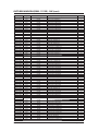
6-8
Samsung Electronics
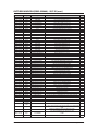
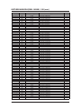
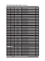
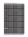
OUTDOOR MAIN PBA(DB92-02866A) - 9K/12K (cont.)
Parts Code
Design Loc
Description
Spec.
TY
2007-000084
2007-000084
2007-000084
2007-000084
2007-000084
2007-000090
2007-000090
2007-000090
2007-000090
2007-000090
2007-000090
2007-000090
2007-000090
2007-000090
2007-000090
2007-000090
2007-000090
2007-000090
2007-000090
2007-000109
2007-000116
2007-000124
2007-000140
2007-000140
2007-000143
2007-000143
2007-000143
2007-000143
2007-000143
2007-000143
2007-000143
2007-000143
2007-000143
2007-000143
2007-000143
2007-000143
2007-000143
2007-000148
2007-000148
2007-000148
2007-000170
2007-000239
2007-000256
2007-000256
2007-000256
2007-000300
2007-000385
2007-000385
2007-000455
2007-000455
2007-000491
2007-000536
2007-000537
2007-000537
2007-000537
2007-000537
2007-000537
2007-000614
2007-000614
2007-000614
2007-000614
2007-000614
2007-000614
2007-000614
R527
R534
R535
R536
R903
R301
R302
R304
R305
R528
R532
R533
R551
R552
R553
R554
R555
R559
R565
R531
R306
R564
R202
R205
R207
R221
R222
R223
R224
R225
R226
R227
R228
R229
R230
R231
R232
R203
R204
R206
R201
R491
R455
R457
R468
R901
R101
R105
R251
R253
R561
R492
R154
R155
R156
R157
R158
R252
R254
R469
R470
R471
R472
R473
R-CHIP
R-CHIP
R-CHIP
R-CHIP
R-CHIP
R-CHIP
R-CHIP
R-CHIP
R-CHIP
R-CHIP
R-CHIP
R-CHIP
R-CHIP
R-CHIP
R-CHIP
R-CHIP
R-CHIP
R-CHIP
R-CHIP
R-CHIP
R-CHIP
R-CHIP
R-CHIP
R-CHIP
R-CHIP
R-CHIP
R-CHIP
R-CHIP
R-CHIP
R-CHIP
R-CHIP
R-CHIP
R-CHIP
R-CHIP
R-CHIP
R-CHIP
R-CHIP
R-CHIP
R-CHIP
R-CHIP
R-CHIP
R-CHIP
R-CHIP
R-CHIP
R-CHIP
R-CHIP
R-CHIP
R-CHIP
R-CHIP
R-CHIP
R-CHIP
R-CHIP
R-CHIP
R-CHIP
R-CHIP
R-CHIP
R-CHIP
R-CHIP
R-CHIP
R-CHIP
R-CHIP
R-CHIP
R-CHIP
R-CHIP
4.7Kohm,5 ,1/10W,TP,1608
4.7Kohm,5 ,1/10W,TP,1608
4.7Kohm,5 ,1/10W,TP,1608
4.7Kohm,5 ,1/10W,TP,1608
4.7Kohm,5 ,1/10W,TP,1608
10Kohm,5 ,1/10W,TP,1608
10Kohm,5 ,1/10W,TP,1608
10Kohm,5 ,1/10W,TP,1608
10Kohm,5 ,1/10W,TP,1608
10Kohm,5 ,1/10W,TP,1608
10Kohm,5 ,1/10W,TP,1608
10Kohm,5 ,1/10W,TP,1608
10Kohm,5 ,1/10W,TP,1608
10Kohm,5 ,1/10W,TP,1608
10Kohm,5 ,1/10W,TP,1608
10Kohm,5 ,1/10W,TP,1608
10Kohm,5 ,1/10W,TP,1608
10Kohm,5 ,1/10W,TP,1608
10Kohm,5 ,1/10W,TP,1608
1Mohm,5 ,1/10W,TP,1608
120ohm,5 ,1/10W,TP,1608
2.2Kohm,5 ,1/10W,TP,1608
1Kohm,5 ,1/16W,TP,1005
1Kohm,5 ,1/16W,TP,1005
4.7Kohm,5 ,1/16W,TP,1005
4.7Kohm,5 ,1/16W,TP,1005
4.7Kohm,5 ,1/16W,TP,1005
4.7Kohm,5 ,1/16W,TP,1005
4.7Kohm,5 ,1/16W,TP,1005
4.7Kohm,5 ,1/16W,TP,1005
4.7Kohm,5 ,1/16W,TP,1005
4.7Kohm,5 ,1/16W,TP,1005
4.7Kohm,5 ,1/16W,TP,1005
4.7Kohm,5 ,1/16W,TP,1005
4.7Kohm,5 ,1/16W,TP,1005
4.7Kohm,5 ,1/16W,TP,1005
4.7Kohm,5 ,1/16W,TP,1005
10Kohm,5 ,1/16W,TP,1005
10Kohm,5 ,1/16W,TP,1005
10Kohm,5 ,1/16W,TP,1005
1Mohm,5 ,1/16W,TP,1005
1.5Kohm,1 ,1/10W,TP,1608
1.6Kohm,1 ,1/10W,TP,1608
1.6Kohm,1 ,1/10W,TP,1608
1.6Kohm,1 ,1/10W,TP,1608
10Kohm,5 ,1/8W,TP,2012
14.3Kohm,1 ,1/4W,TP,3216
14.3Kohm,1 ,1/4W,TP,3216
18Kohm,1 ,1/10W,TP,1608
18Kohm,1 ,1/10W,TP,1608
2.2Kohm,1 ,1/10W,TP,1608
200ohm,1 ,1/10W,TP,1608
200ohm,1 ,1/4W,TP,3216
200ohm,1 ,1/4W,TP,3216
200ohm,1 ,1/4W,TP,3216
200ohm,1 ,1/4W,TP,3216
200ohm,1 ,1/4W,TP,3216
24Kohm,1 ,1/10W,TP,1608
24Kohm,1 ,1/10W,TP,1608
24Kohm,1 ,1/10W,TP,1608
24Kohm,1 ,1/10W,TP,1608
24Kohm,1 ,1/10W,TP,1608
24Kohm,1 ,1/10W,TP,1608
24Kohm,1 ,1/10W,TP,1608
1
1
1
1
1
1
1
1
1
1
1
1
1
1
1
1
1
1
1
1
1
1
1
1
1
1
1
1
1
1
1
1
1
1
1
1
1
1
1
1
1
1
1
1
1
1
1
1
1
1
1
1
1
1
1
1
1
1
1
1
1
1
1
1
Samsung Electronics
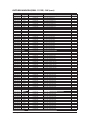
6-9
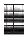
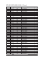
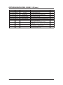
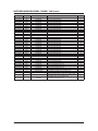
OUTDOOR MAIN PBA(DB92-02866A) - 9K/12K (cont.)
Parts Code
Design Loc
Description
Spec.
TY
2007-000614
2007-000651
2007-000683
2007-000683
2007-000683
2007-000763
2007-000763
2007-000872
2007-000872
2007-000872
2007-000924
2007-000924
2007-000924
2007-000924
2007-000924
2007-000924
2007-000979
2007-001071
2007-001175
2007-001175
2007-001175
2007-010245
2007-010245
2007-010245
2007-010245
2007-010245
2201-000540
2201-002002
2201-002002
2201-002002
2201-002002
2201-002427
2203-000236
2203-000257
2203-000257
2203-000257
2203-000257
2203-000257
2203-000257
2203-000257
2203-000257
2203-000257
2203-000440
2203-000440
2203-000440
2203-000440
2203-000440
2203-000440
2203-000440
2203-000440
2203-000440
2203-000440
2203-000440
2203-000440
2203-000440
2203-000440
2203-000440
2203-000440
2203-000440
2203-000783
2203-000783
2203-002002
2203-002002
2203-002002
R474
R475
R454
R459
R466
R476
R477
R801
R802
R803
R102
R103
R104
R106
R107
R108
R478
R902
R409
R423
R427
R410
R411
R412
R425
R426
C425
C004
C005
C012
C013
C901
C421
C222
C223
C224
C225
C301
C351
C352
C422
C423
C404
C405
C406
C408
C409
C410
C411
C501
C504
C505
C506
C507
C508
C510
C512
C523
C904
C455
C458
C453
C454
C459
R-CHIP
R-CHIP
R-CHIP
R-CHIP
R-CHIP
R-CHIP
R-CHIP
R-CHIP
R-CHIP
R-CHIP
R-CHIP
R-CHIP
R-CHIP
R-CHIP
R-CHIP
R-CHIP
R-CHIP
R-CHIP
R-CHIP
R-CHIP
R-CHIP
R-CHIP
R-CHIP
R-CHIP
R-CHIP
R-CHIP
C-CERAMIC,DISC
C-CERAMIC,DISC
C-CERAMIC,DISC
C-CERAMIC,DISC
C-CERAMIC,DISC
C-CERAMIC,DISC
C-CER,CHIP
C-CER,CHIP
C-CER,CHIP
C-CER,CHIP
C-CER,CHIP
C-CER,CHIP
C-CER,CHIP
C-CER,CHIP
C-CER,CHIP
C-CER,CHIP
C-CER,CHIP
C-CER,CHIP
C-CER,CHIP
C-CER,CHIP
C-CER,CHIP
C-CER,CHIP
C-CER,CHIP
C-CER,CHIP
C-CER,CHIP
C-CER,CHIP
C-CER,CHIP
C-CER,CHIP
C-CER,CHIP
C-CER,CHIP
C-CER,CHIP
C-CER,CHIP
C-CER,CHIP
C-CER,CHIP
C-CER,CHIP
C-CER,CHIP
C-CER,CHIP
C-CER,CHIP
24Kohm,1 ,1/10W,TP,1608
27Kohm,1 ,1/10W,TP,1608
3.3Kohm,1 ,1/10W,TP,1608
3.3Kohm,1 ,1/10W,TP,1608
3.3Kohm,1 ,1/10W,TP,1608
330ohm,1 ,1/10W,TP,1608
330ohm,1 ,1/10W,TP,1608
4.7Kohm,5 ,1/8W,TP,2012
4.7Kohm,5 ,1/8W,TP,2012
4.7Kohm,5 ,1/8W,TP,2012
470Kohm,1 ,1/4W,TP,3216
470Kohm,1 ,1/4W,TP,3216
470Kohm,1 ,1/4W,TP,3216
470Kohm,1 ,1/4W,TP,3216
470Kohm,1 ,1/4W,TP,3216
470Kohm,1 ,1/4W,TP,3216
5.6Kohm,1 ,1/10W,TP,1608
6.8Kohm,5 ,1/8W,TP,2012
8.2Kohm,1 ,1/10W,TP,1608
8.2Kohm,1 ,1/10W,TP,1608
8.2Kohm,1 ,1/10W,TP,1608
0.01ohm,1 ,2W,TP,6432
0.01ohm,1 ,2W,TP,6432
0.01ohm,1 ,2W,TP,6432
0.01ohm,1 ,2W,TP,6432
0.01ohm,1 ,2W,TP,6432
4.7nF,20 ,2000V,Y5U,12x5mm,10mm
4.7nF,20 ,400V,Y5U,16x6mm,10mm
4.7nF,20 ,400V,Y5U,16x6mm,10mm
4.7nF,20 ,400V,Y5U,16x6mm,10mm
4.7nF,20 ,400V,Y5U,16x6mm,10mm
2.2nF,K(10 ),2000V,Y5P,12.5x5mm,7.5mm
0.1nF,5 ,50V,C0G,TP,1608
10nF,10 ,50V,X7R,TP,1608
10nF,10 ,50V,X7R,TP,1608
10nF,10 ,50V,X7R,TP,1608
10nF,10 ,50V,X7R,TP,1608
10nF,10 ,50V,X7R,TP,1608
10nF,10 ,50V,X7R,TP,1608
10nF,10 ,50V,X7R,TP,1608
10nF,10 ,50V,X7R,TP,1608
10nF,10 ,50V,X7R,TP,1608
1nF,10 ,50V,X7R,TP,1608
1nF,10 ,50V,X7R,TP,1608
1nF,10 ,50V,X7R,TP,1608
1nF,10 ,50V,X7R,TP,1608
1nF,10 ,50V,X7R,TP,1608
1nF,10 ,50V,X7R,TP,1608
1nF,10 ,50V,X7R,TP,1608
1nF,10 ,50V,X7R,TP,1608
1nF,10 ,50V,X7R,TP,1608
1nF,10 ,50V,X7R,TP,1608
1nF,10 ,50V,X7R,TP,1608
1nF,10 ,50V,X7R,TP,1608
1nF,10 ,50V,X7R,TP,1608
1nF,10 ,50V,X7R,TP,1608
1nF,10 ,50V,X7R,TP,1608
1nF,10 ,50V,X7R,TP,1608
1nF,10 ,50V,X7R,TP,1608
0.33nF,5 ,50V,C0G,TP,1608
0.33nF,5 ,50V,C0G,TP,1608
0.033nF,5 ,50V,NP0,TP,1608
0.033nF,5 ,50V,NP0,TP,1608
0.033nF,5 ,50V,NP0,TP,1608
1
1
1
1
1
1
1
1
1
1
1
1
1
1
1
1
1
1
1
1
1
1
1
1
1
1
1
1
1
1
1
1
1
1
1
1
1
1
1
1
1
1
1
1
1
1
1
1
1
1
1
1
1
1
1
1
1
1
1
1
1
1
1
1
6-10
Samsung Electronics
OUTDOOR MAIN PBA(DB92-02866A) - 9K/12K (cont.)
Parts Code
Design Loc
Description
Spec.
TY
2203-002002
2203-002002
2203-002002
2203-002002
2203-002002
2203-002398
2203-005249
2203-005249
2203-005249
2203-005249
2203-005249
2203-005249
2203-005249
2203-005249
2203-005249
2203-005249
2203-005249
2203-005249
2203-005249
2203-005249
2203-005249
2203-005249
2203-005249
2203-005249
2203-005249
2203-005249
2203-005249
2203-005249
2203-005249
2203-005249
2203-005249
2203-005249
2203-005249
2203-005249
2203-005249
2203-005249
2203-005249
2203-005249
2203-005249
2203-005249
2203-005249
2203-005249
2203-005249
2203-005249
2203-005249
2203-005249
2203-006158
2203-006158
2203-006158
2203-006158
2203-006158
2203-006158
2203-006158
2203-006158
2203-006158
2203-006460
2203-006960
2203-007456
2203-007456
2203-007456
2203-007456
2203-007456
2203-007456
C515
C516
C517
C518
C519
C524
C061
C151
C152
C153
C154
C162
C163
C220
C221
C251
C252
C253
C254
C302
C303
C304
C305
C306
C307
C401
C402
C403
C407
C420
C424
C460
C503
C509
C511
C514
C520
C521
C525
C526
C527
C701
C702
C703
C704
C903
C201
C203
C204
C206
C207
C208
C210
C211
C212
C522
C902
C202
C205
C209
C213
C214
C226
C-CER,CHIP
C-CER,CHIP
C-CER,CHIP
C-CER,CHIP
C-CER,CHIP
C-CER,CHIP
C-CER,CHIP
C-CER,CHIP
C-CER,CHIP
C-CER,CHIP
C-CER,CHIP
C-CER,CHIP
C-CER,CHIP
C-CER,CHIP
C-CER,CHIP
C-CER,CHIP
C-CER,CHIP
C-CER,CHIP
C-CER,CHIP
C-CER,CHIP
C-CER,CHIP
C-CER,CHIP
C-CER,CHIP
C-CER,CHIP
C-CER,CHIP
C-CER,CHIP
C-CER,CHIP
C-CER,CHIP
C-CER,CHIP
C-CER,CHIP
C-CER,CHIP
C-CER,CHIP
C-CER,CHIP
C-CER,CHIP
C-CER,CHIP
C-CER,CHIP
C-CER,CHIP
C-CER,CHIP
C-CER,CHIP
C-CER,CHIP
C-CER,CHIP
C-CER,CHIP
C-CER,CHIP
C-CER,CHIP
C-CER,CHIP
C-CER,CHIP
C-CER,CHIP
C-CER,CHIP
C-CER,CHIP
C-CER,CHIP
C-CER,CHIP
C-CER,CHIP
C-CER,CHIP
C-CER,CHIP
C-CER,CHIP
C-CER,CHIP
C-CER,CHIP
C-CER,CHIP
C-CER,CHIP
C-CER,CHIP
C-CER,CHIP
C-CER,CHIP
C-CER,CHIP
0.033nF,5 ,50V,NP0,TP,1608
0.033nF,5 ,50V,NP0,TP,1608
0.033nF,5 ,50V,NP0,TP,1608
0.033nF,5 ,50V,NP0,TP,1608
0.033nF,5 ,50V,NP0,TP,1608
22nF,10 ,50V,X7R,TP,1608
100nF,10 ,50V,X7R,TP,1608
100nF,10 ,50V,X7R,TP,1608
100nF,10 ,50V,X7R,TP,1608
100nF,10 ,50V,X7R,TP,1608
100nF,10 ,50V,X7R,TP,1608
100nF,10 ,50V,X7R,TP,1608
100nF,10 ,50V,X7R,TP,1608
100nF,10 ,50V,X7R,TP,1608
100nF,10 ,50V,X7R,TP,1608
100nF,10 ,50V,X7R,TP,1608
100nF,10 ,50V,X7R,TP,1608
100nF,10 ,50V,X7R,TP,1608
100nF,10 ,50V,X7R,TP,1608
100nF,10 ,50V,X7R,TP,1608
100nF,10 ,50V,X7R,TP,1608
100nF,10 ,50V,X7R,TP,1608
100nF,10 ,50V,X7R,TP,1608
100nF,10 ,50V,X7R,TP,1608
100nF,10 ,50V,X7R,TP,1608
100nF,10 ,50V,X7R,TP,1608
100nF,10 ,50V,X7R,TP,1608
100nF,10 ,50V,X7R,TP,1608
100nF,10 ,50V,X7R,TP,1608
100nF,10 ,50V,X7R,TP,1608
100nF,10 ,50V,X7R,TP,1608
100nF,10 ,50V,X7R,TP,1608
100nF,10 ,50V,X7R,TP,1608
100nF,10 ,50V,X7R,TP,1608
100nF,10 ,50V,X7R,TP,1608
100nF,10 ,50V,X7R,TP,1608
100nF,10 ,50V,X7R,TP,1608
100nF,10 ,50V,X7R,TP,1608
100nF,10 ,50V,X7R,TP,1608
100nF,10 ,50V,X7R,TP,1608
100nF,10 ,50V,X7R,TP,1608
100nF,10 ,50V,X7R,TP,1608
100nF,10 ,50V,X7R,TP,1608
100nF,10 ,50V,X7R,TP,1608
100nF,10 ,50V,X7R,TP,1608
100nF,10 ,50V,X7R,TP,1608
100nF,10 ,16V,X7R,TP,1005,0.5T
100nF,10 ,16V,X7R,TP,1005,0.5T
100nF,10 ,16V,X7R,TP,1005,0.5T
100nF,10 ,16V,X7R,TP,1005,0.5T
100nF,10 ,16V,X7R,TP,1005,0.5T
100nF,10 ,16V,X7R,TP,1005,0.5T
100nF,10 ,16V,X7R,TP,1005,0.5T
100nF,10 ,16V,X7R,TP,1005,0.5T
100nF,10 ,16V,X7R,TP,1005,0.5T
2200nF,10 ,16V,X5R,TP,1608,1000nF,10 ,50V,X7R,TP,2012
1000nF,10 ,25V,X5R,TP,1005,0.5T
1000nF,10 ,25V,X5R,TP,1005,0.5T
1000nF,10 ,25V,X5R,TP,1005,0.5T
1000nF,10 ,25V,X5R,TP,1005,0.5T
1000nF,10 ,25V,X5R,TP,1005,0.5T
1000nF,10 ,25V,X5R,TP,1005,0.5T
1
1
1
1
1
1
1
1
1
1
1
1
1
1
1
1
1
1
1
1
1
1
1
1
1
1
1
1
1
1
1
1
1
1
1
1
1
1
1
1
1
1
1
1
1
1
1
1
1
1
1
1
1
1
1
1
1
1
1
1
1
1
1
Samsung Electronics
6-11
OUTDOOR MAIN PBA(DB92-02866A) - 9K/12K (cont.)
Parts Code
2203-007456
2203-007456
2203-007456
2301-001285
2301-001285
2306-000123
2401-000303
2401-000303
2401-001838
2401-002438
2401-003224
2401-003585
2401-004874
2401-004874
2401-004874
2402-001183
2402-001268
2402-001268
2402-001268
2402-001368
2402-001368
2402-001368
2802-001165
2802-001211
3501-001154
3501-001154
3501-001279
3601-001538
3711-000015
3711-000024
3711-000177
3711-000203
3711-000296
3711-000760
3711-000879
3711-000880
3711-000998
3711-000999
3711-002001
3711-003404
3711-003843
3711-007656
3711-007659
3711-007817
3712-001047
3712-001139
3712-001139
4715-001093
4719-002483
4719-002484
DB27-00097A
DB41-01227A
DB61-05296A
DB61-05916A
Design Loc
Description
C227
C-CER,CHIP
C228
C-CER,CHIP
C229
C-CER,CHIP
C001
C-FILM,LEAD-PPF
C006
C-FILM,LEAD-PPF
C412
C-FILM,LEAD-PPF
CE162
C-AL
CE163
C-AL
CE151
C-AL
CE902
C-AL
CE152
C-AL
CE901
C-AL
CE101
C-AL
CE102
C-AL
CE103
C-AL
CE451
C-AL,SMD
CE153
C-AL,SMD
CE404
C-AL,SMD
CE420
C-AL,SMD
CE401
C-AL,SMD
CE402
C-AL,SMD
CE403
C-AL,SMD
X201
RESONATOR-CERAMIC
X501
RESONATOR-CERAMIC
RY022
RELAY-MINIATURE
RY030
RELAY-MINIATURE
RY021
RELAY-POWER
F001
FUSE-AXIAL LEAD
CN203
HEADER-BOARD TO CABLE
CN202
HEADER-BOARD TO CABLE
CN301
HEADER-BOARD TO CABLE
CN030
HEADER-BOARD TO CABLE
CN901
HEADER-BOARD TO CABLE
CN551
HEADER-BOARD TO CABLE
CN152
HEADER-BOARD TO CABLE
CN151
HEADER-BOARD TO CABLE
CN701
CONNECTOR-HEADER
CN204
HEADER-BOARD TO CABLE
CN201
HEADER-BOARD TO CABLE
CN150
HEADER-BOARD TO CABLE
CN251
HEADER-BOARD TO CABLE
CN402
HEADER-BOARD TO CABLE
CN401
HEADER-BOARD TO CABLE
CN501
HEADER-BOARD TO BOARD
CN003
CONNECTOR-Terminal
CN001
CONNECTOR-Terminal
CN002
CONNECTOR-Terminal
DSA001
SURGE ABSORBER
PFC050
POWER MODULE
IPM400
POWER MODULE
FT001
COIL CHOKE
PCB MAIN
PCB MAIN
SUPPORT-IC
SUPPORT-IC
SUPPORTSUPPORT-PCB
PCB
DB91-01517A
IC501
ASSY MICOM
0903-001843
-
IC-MICROCONTROLLER
DB91-01534A
IC201
ASSY MICOM
DB09-00596A
-
IC MICOM
6-12
Spec.
TY
1000nF,10 ,25V,X5R,TP,1005,0.5T
1000nF,10 ,25V,X5R,TP,1005,0.5T
1000nF,10 ,25V,X5R,TP,1005,0.5T
680nF,10 ,275V,BK,31x11x21mm
680nF,10 ,275V,BK,31x11x21mm
100nF,5 ,630V,BK,26x16.5x8.5mm
100uF,20 ,25V,WT,TP,6.3x11mm,5mm
100uF,20 ,25V,WT,TP,6.3x11mm,5mm
470uF,20 ,25V,WT,TP,10x16,5mm
47uF,20 ,50V,WT,TP,6.3x11,5mm
470uF,20 ,16V,WT,TP,8X11.5,5mm
220uF,20 ,35V,WT,TP,8x11.5mm,5
330uF,20 ,400V,BK,25.450,10mm
330uF,20 ,400V,BK,25.450,10mm
330uF,20 ,400V,BK,25.450,10mm
22UF,20 ,16V,WT,TP,5.3X5.3X6MM
100uF,20 ,25V,WT,TP,8x6.3mm
100uF,20 ,25V,WT,TP,8x6.3mm
100uF,20 ,25V,WT,TP,8x6.3mm
47uF,20 ,25V,TP,6.3x4.9mm
47uF,20 ,25V,TP,6.3x4.9mm
47uF,20 ,25V,TP,6.3x4.9mm
4MHz,0.5 ,TP,4.5x2.0x1.15mm
8MHZ,0.1 ,TP,3.2X1.3X0.9 MM
12V,200mW,3000mA,1FormA,10ms,10ms
12V,200mW,3000mA,1FormA,10ms,10ms
12V DC,400mW,16000mA,1Form A,15mS,5mS
250V,15A,TIME-LAG,CERAMIC,6.35x31.8mm
BOX,2P,1R,2.5MM,STRAIGHT,SN,WHT
BOX,3P,1R,2.5MM,STRAIGHT,SN,WHT
1WALL,2P,1R,3.96MM,STRAIGHT,SN,RED
1WALL,2P/3P,1R,7.92mm,STRAIGHT,SN,WHT
1WALL,6P,1R,3.96MM,STRAIGHT,SN,WHT
BOX,20P,2R,2MM,ANGLE,SN,BLK
BOX,3P,1R,2.5mm,STRAIGHT,SN,BLU
BOX,3P,1R,2.5MM,STRAIGHT,SN,RED
BOX,5P,1R,2.5MM,STRAIGHT,SN,RED
BOX,5P,1R,2.5mm,STRAIGHT,SN,WHT
BOX,20P,2R,2MM,STRAIGHT,SN,BLK
1WALL,2P,1R,7.92mm,STRAIGHT,SN,BLU
BOX,8P,1R,2mm,STRAIGHT,SN,WHT
BOX,3,1R,6mm,STRAIGHT,WHT
BOX,2,1R,7.92mm,STRAIGHT,WHT
3WALL,7P,1R,2mm,STRAIGHT,SN,WHT
TAB,MALE,N,0.5/4.75mm
TAB,MALE,6.35x0.8mm
TAB,MALE,6.35x0.8mm
3600V,20 ,2000A,-,AXIAL
Smart Power Module,FPAB20BH60B,600V,20A,89W,20kHz,PFCM
Smart Power Module,FNA41560B2,600V,15A,41W,20kHz
CC-35-15SS,SI,3.5mH,+50-30 ,15mohm Max,15A,-25+115
FR-4,2Layer,142197,PF#2,OUTDOOR,2Oz,142197
AFX-HD233A,PA66,FR50,BLACK
1
1
1
1
1
1
1
1
1
1
1
1
1
1
1
1
1
1
1
1
1
1
1
1
1
1
1
1
1
1
1
1
1
1
1
1
1
1
1
1
1
1
1
1
1
1
1
1
1
1
1
1
1
XS01_V2MD,HIPS,S834S1,15.5g,BLACK
1
Soc 1Phase PF2,PF3,PF4,PF6,STM-125F-OA, HART-I910, 64LQFP, ROM
64KB
HART-I910,LQFP,64Z30,12x12mm,8MHz,5V,600mW,40to+85C,12KB,64KB,Inverter SOC,Inverter SOC
RAC A3050 Outdoor Micom,STM-130C-OS, S3FM02G, 128TQFP, ROM
384KB
S3FM02G,128P,DC3V,TQFP,-40+85,384K
1
1
1
1
Samsung Electronics
6-5 OUTDOOR MAIN PBA(DB93-10939K) - 18K
Parts Code
Design Loc
Parts Description
1203-000002
IC107
IC-POSI.ADUST REG.
1203-002735
IC104
IC-POSI.FIXED REG.
1203-006089
IC101
IC-PWM CONTROLLER
1404-001274
1404-001498
1405-000154
1405-000154
1405-000160
1405-000160
3501-001154
3501-001154
3501-001268
3704-001601
3711-000179
3711-000203
3711-000880
3711-004019
3711-004379
3711-005096
3711-005716
3711-006337
3711-006714
3711-006715
3711-007706
3712-001047
3712-001139
3712-001139
3712-001139
3712-001139
3712-001139
3712-001139
3712-001139
4719-002485
NTC101
PTC001
VA001
VA003
VA002
VA101
RY002
RY003
RY001
IC701
CN301
CN001
CN513
CN901
CN510
CN509
CN512
CN503
CN502
CN501
CN201
EARTH
REACTOR1
REACTOR2
TB-L
TB-N
U
V
W
IPM
THERMISTOR-NTC
THERMISTOR-PTC
VARISTOR
VARISTOR
VARISTOR
VARISTOR
RELAY-MINIATURE
RELAY-MINIATURE
RELAY-POWER
SOCKET-IC
HEADER-BOARD TO CABLE
HEADER-BOARD TO CABLE
HEADER-BOARD TO CABLE
CONNECTOR-HEADER
HEADER-BOARD TO CABLE
HEADER-BOARD TO CABLE
HEADER-BOARD TO CABLE
CONNECTOR-HEADER
HEADER-BOARD TO CABLE
HEADER-BOARD TO CABLE
HEADER-BOARD TO CABLE
CONNECTOR-Terminal
CONNECTOR-Terminal
CONNECTOR-Terminal
CONNECTOR-Terminal
CONNECTOR-Terminal
CONNECTOR-Terminal
CONNECTOR-Terminal
CONNECTOR-Terminal
POWER MODULE
4719-002486
PFCM
POWER MODULE
DB26-00120A
PT001
TRANS SWITCHING
DB27-00034A
B405
COIL-BEAD
DB27-00070A
FT301
COIL CHOKE
DB27-00078A
DB61-05296A
DB94-04162B
0402-000137
2003-000855
2009-001145
2009-001145
2009-001145
2201-000322
2201-000322
2201-000322
2201-000446
2201-000446
2201-000446
2201-000446
2201-000540
2201-000551
2201-000987
2201-000987
2301-001285
FT001
D101
R101
R413
R414
R415
C101
C102
C901
C003
C004
C005
C006
C807
C114
C111
C112
C002
COIL FILTER
SUPPORT-IC
ASSY PCB AUTO
DIODE-RECTIFIER
R-METAL OXIDE(S)
R-METAL PLATE
R-METAL PLATE
R-METAL PLATE
C-CERAMIC,DISC
C-CERAMIC,DISC
C-CERAMIC,DISC
C-CERAMIC,DISC
C-CERAMIC,DISC
C-CERAMIC,DISC
C-CERAMIC,DISC
C-CERAMIC,DISC
C-CERAMIC,DISC
C-CERAMIC,DISC
C-CERAMIC,DISC
C-FILM,LEAD-PPF
Samsung Electronics
Spec.
431,TO-92,3P,-,PLASTIC,2.44/2.58V,775MV,0TO+70C,100MA,,ST,KIA7815API,TO-220IS,3P,10.3x15.3mm,PLASTIC,15V,2W,30to+150,1A,-,ST
TOP253PN,DIP,7P,6.35x9.57mm,PLASTIC,-0.3V/700V,15W,40Cto+150C,1.37A,ST
22ohm,1.4A,3100K,9.5mW/C,-,7.0,40ohm,25 ,290Vac,7A,TR
560V,460Vdc,4500A,17.5x7.5mm,BK,920V,600pF
560V,460Vdc,4500A,17.5x7.5mm,BK,920V,600pF
680V,560Vdc,4500A,17.5x6.5mm,TP,1120V,250pF
680V,560Vdc,4500A,17.5x6.5mm,TP,1120V,250pF
12V,200mW,3000mA,1FormA,10ms,10ms
12V,200mW,3000mA,1FormA,10ms,10ms
12V,0.9W,25000mA,1FormA,20ms,10ms
8P,SN,2.54mm
1WALL,2P,1R,3.96MM,STRAIGHT,SN,YEL
1WALL,2P/3P,1R,7.92mm,STRAIGHT,SN,WHT
BOX,3P,1R,2.5MM,STRAIGHT,SN,RED
1WALL,6P,1R,3.96mm,ANGLE,SN,WHT
BOX,4P,1R,2mm,STRAIGHT,SN,WHT
BOX,5P,1R,2MM,STRAIGHT,SN,BLK
BOX,10P,1R,2mm,STRAIGHT,SN,BLK
BOX,5P,1R,2.5mm,ANGLE,SN,RED
BOX,4P,1R,2.5mm,ANGLE,SN,RED
BOX,4P,1R,2.5mm,ANGLE,SN,WHT
BOX,10P,1R,2mm,STRAIGHT,SN,RED
TAB,MALE,N,0.5/4.75mm
TAB,MALE,6.35x0.8mm
TAB,MALE,6.35x0.8mm
TAB,MALE,6.35x0.8mm
TAB,MALE,6.35x0.8mm
TAB,MALE,6.35x0.8mm
TAB,MALE,6.35x0.8mm
TAB,MALE,6.35x0.8mm
Smart Power Module,FSBB30CH60C,600V,30A,106W,20kHz
Smart Power Module,FPAB30BH60B,600V,30A,104W,20kHz,PF
CM
EE2525,TOP253PN(SI-INV),220V,EE2525,18.6V, 12V,
6V,EE2525,50/60Hz,1.32mH,18.6V, 12V, 6V,SI-INVERTER, 12W
BI-3857,1.2uH MIN,-,-,1,-,-,BEAD,4575ohm,5.7X3.5X61.5mm,,2060,TAPING
CV005180SF3,SF2,18.0,+5030 ,430mohm,13159,8.4/3.4,4.0,-30+105
MALDIVE,12mH,22m,20A
AFX-HD233A,PA66,FR50,BLACK
OUTDOOR,A3050,Y,5V,12V,15V,3.3V,OLD PF#3,DB93-10939K
1N4007,1000V,1A,DO-41,TP
47Kohm,5 ,3W,AA,TP,5.6x16mm
0.005ohm,5 ,5W,AA,BK,14.5x5.0x18.0mm
0.005ohm,5 ,5W,AA,BK,14.5x5.0x18.0mm
0.005ohm,5 ,5W,AA,BK,14.5x5.0x18.0mm
2.2nF,10 ,2000V,Y5P,TP,13x5mm,10mm
2.2nF,10 ,2000V,Y5P,TP,13x5mm,10mm
2.2nF,10 ,2000V,Y5P,TP,13x5mm,10mm
3.3nF,20 ,400V,Y5U,TP,15x6mm,10mm
3.3nF,20 ,400V,Y5U,TP,15x6mm,10mm
3.3nF,20 ,400V,Y5U,TP,15x6mm,10mm
3.3nF,20 ,400V,Y5U,TP,15x6mm,10mm
4.7nF,20 ,2000V,Y5U,12x5mm,10mm
0.47nF,10 ,1000V,Y5P,6.3x5mm,5mm
2.2nF,20 ,400V,Y5U,TP,12.5x6mm,10mm
2.2nF,20 ,400V,Y5U,TP,12.5x6mm,10mm
680nF,10 ,275V,BK,31x11x21mm
uantity
1
1
1
1
1
1
1
1
1
1
1
1
1
1
1
1
1
1
1
1
1
1
1
1
1
1
1
1
1
1
1
1
1
1
1
1
1
1
2
1
1
1
1
1
1
1
1
1
1
1
1
1
1
1
1
1
1
6-13
OUTDOOR MAIN PBA(DB93-10939K) - 18K (cont.)
Parts Code
Design Loc
Parts Description
Spec.
uantity
2301-001949
2306-000123
2306-000123
2401-000481
2401-000880
2401-001548
2401-001838
2401-001838
2401-001838
2401-002438
2401-003069
2401-003224
2401-003224
2401-003224
2401-003224
2401-004267
2401-004929
2401-004929
2401-004929
2401-004929
2702-001110
2702-001110
3601-001652
4715-001093
C001
C414
C806
CE109
CE901
CE102
CE104
CE108
CE110
CE902
CE103
CE105
CE106
CE107
CE451
CE101
CE001
CE002
CE003
CE004
L102
L103
F001
DSA001
C-FILM,LEAD
C-FILM,LEAD-PPF
C-FILM,LEAD-PPF
C-AL
C-AL
C-AL
C-AL
C-AL
C-AL
C-AL
C-AL
C-AL
C-AL
C-AL
C-AL
C-AL
C-AL
C-AL
C-AL
C-AL
INDUCTOR-RADIAL
INDUCTOR-RADIAL
FUSE-AXIAL LEAD
SURGE ABSORBER
1
1
1
1
1
1
1
1
1
1
1
1
1
1
1
1
1
1
1
1
1
1
1
1
DB27-00034A
B401
COIL-BEAD
DB27-00034A
B402
COIL-BEAD
DB27-00034A
B403
COIL-BEAD
DB27-00034A
B404
COIL-BEAD
DB27-00034A
B901
COIL-BEAD
DB27-00034A
B902
COIL-BEAD
DB94-04162C
0401-001099
0401-001099
0401-001099
0401-001099
0401-001099
0401-001099
0401-001099
0401-001099
0401-001099
0401-001099
0401-001099
0401-001099
0401-001099
0401-001099
0401-001099
0401-001099
0402-001097
0402-001192
0402-001192
0402-001192
0402-001298
0402-001427
0403-001499
0403-001499
0404-001020
0404-001020
0404-001020
D001
D002
D003
D201
D202
D204
D205
D206
D207
D208
D501
D502
D503
D504
D901
D902
D106
D103
D104
D105
BD101
D102
ZD401
ZD801
D203
D401
D402
ASSY PCB SMD
DIODE-SWITCHING
DIODE-SWITCHING
DIODE-SWITCHING
DIODE-SWITCHING
DIODE-SWITCHING
DIODE-SWITCHING
DIODE-SWITCHING
DIODE-SWITCHING
DIODE-SWITCHING
DIODE-SWITCHING
DIODE-SWITCHING
DIODE-SWITCHING
DIODE-SWITCHING
DIODE-SWITCHING
DIODE-SWITCHING
DIODE-SWITCHING
DIODE-SCHOTTKY
DIODE-RECTIFIER
DIODE-RECTIFIER
DIODE-RECTIFIER
DIODE-BRIDGE
DIODE-RECTIFIER
DIODE-ZENER
DIODE-ZENER
DIODE-SCHOTTKY
DIODE-SCHOTTKY
DIODE-SCHOTTKY
3300nF,10 ,275V,BK,31x21x31mm
100nF,5 ,630V,BK,26x16.5x8.5mm
100nF,5 ,630V,BK,26x16.5x8.5mm
10uF,20 ,50V,WT,TP,5x11,5
220uF,20 ,50V,WT,TP,10x16mm,5m
47uF,20 ,25V,WT,TP,5x11,5
470uF,20 ,25V,WT,TP,10x16,5mm
470uF,20 ,25V,WT,TP,10x16,5mm
470uF,20 ,25V,WT,TP,10x16,5mm
47uF,20 ,50V,WT,TP,6.3x11,5mm
470uF,20 ,50V,WT,TP,10x20mm,5
470uF,20 ,16V,WT,TP,8X11.5,5mm
470uF,20 ,16V,WT,TP,8X11.5,5mm
470uF,20 ,16V,WT,TP,8X11.5,5mm
470uF,20 ,16V,WT,TP,8X11.5,5mm
22uF,20 ,500V,TP,1625,7.5mm
390uF,20 ,400V,BK,10mm
390uF,20 ,400V,BK,10mm
390uF,20 ,400V,BK,10mm
390uF,20 ,400V,BK,10mm
33uH,10 ,9.5x16mm
33uH,10 ,9.5x16mm
250V,30A,TIME-LAG,CERAMIC,6.35x31.8mm
3600V,20 ,2000A,-,AXIAL
BI-3857,1.2uH MIN,-,-,1,-,-,BEAD,4575ohm,5.7X3.5X61.5mm,,2060,TAPING
BI-3857,1.2uH MIN,-,-,1,-,-,BEAD,4575ohm,5.7X3.5X61.5mm,,2060,TAPING
BI-3857,1.2uH MIN,-,-,1,-,-,BEAD,4575ohm,5.7X3.5X61.5mm,,2060,TAPING
BI-3857,1.2uH MIN,-,-,1,-,-,BEAD,4575ohm,5.7X3.5X61.5mm,,2060,TAPING
BI-3857,1.2uH MIN,-,-,1,-,-,BEAD,4575ohm,5.7X3.5X61.5mm,,2060,TAPING
BI-3857,1.2uH MIN,-,-,1,-,-,BEAD,4575ohm,5.7X3.5X61.5mm,,2060,TAPING
OUTDOOR,A3050,Y,5V,12V,15V,3.3V,OLD PF#3,DB93-10939K
1N4148WS,75V,150mA,SOD-323,TP
1N4148WS,75V,150mA,SOD-323,TP
1N4148WS,75V,150mA,SOD-323,TP
1N4148WS,75V,150mA,SOD-323,TP
1N4148WS,75V,150mA,SOD-323,TP
1N4148WS,75V,150mA,SOD-323,TP
1N4148WS,75V,150mA,SOD-323,TP
1N4148WS,75V,150mA,SOD-323,TP
1N4148WS,75V,150mA,SOD-323,TP
1N4148WS,75V,150mA,SOD-323,TP
1N4148WS,75V,150mA,SOD-323,TP
1N4148WS,75V,150mA,SOD-323,TP
1N4148WS,75V,150mA,SOD-323,TP
1N4148WS,75V,150mA,SOD-323,TP
1N4148WS,75V,150mA,SOD-323,TP
1N4148WS,75V,150mA,SOD-323,TP
B140,40V,1000mA,DO-214AC,TP
ES2D,200V,2A,SMB,TP
ES2D,200V,2A,SMB,TP
ES2D,200V,2A,SMB,TP
DF06S,600V,1A,SMD-4,TP
ES1D,200V,1A,DO-214AC,TP
MMSZ5252B,22.8/25.2V,500mW,SOD-123,TP
MMSZ5252B,22.8/25.2V,500mW,SOD-123,TP
BAT54C,30V,200mA,SOT-23,TP
BAT54C,30V,200mA,SOT-23,TP
BAT54C,30V,200mA,SOT-23,TP
6-14
1
1
1
1
1
1
1
1
1
1
1
1
1
1
1
1
1
1
1
1
1
1
1
1
1
1
1
1
1
1
1
1
1
1
Samsung Electronics
OUTDOOR MAIN PBA(DB93-10939K) - 18K (cont.)
Parts Code
Design Loc
Parts Description
Spec.
uantity
0404-001020
0404-001020
0404-001020
0404-001020
0404-001020
0406-001204
0406-001204
0406-001204
0406-001204
0407-000123
0501-000463
0501-000463
0504-000127
0506-000175
0506-000175
0601-002423
0601-002955
0601-002956
0601-002956
0604-001172
0604-001172
0604-001172
0604-001172
0604-001172
D451
D452
D453
D454
D456
CD301
CD302
CD303
CD304
D601
Q651
Q652
Q902
IC502
IC503
LED501
LED503
LED201
LED502
IC103
IC106
IC202
IC203
IC651
DIODE-SCHOTTKY
DIODE-SCHOTTKY
DIODE-SCHOTTKY
DIODE-SCHOTTKY
DIODE-SCHOTTKY
DIODE-TVS
DIODE-TVS
DIODE-TVS
DIODE-TVS
DIODE-SWITCHING
TR-SMALL SIGNAL
TR-SMALL SIGNAL
TR-DIGITAL
TR-ARRAY
TR-ARRAY
LED
LED
LED
LED
PHOTO-COUPLER
PHOTO-COUPLER
PHOTO-COUPLER
PHOTO-COUPLER
PHOTO-COUPLER
1
1
1
1
1
1
1
1
1
1
1
1
1
1
1
1
1
1
1
1
1
1
1
1
0801-000393
IC302
IC-CMOS LOGIC
1006-001325
IC301
IC-BUS TRANSCEIVER
1201-002946
IC451
IC-OP AMP
1201-002946
IC452
IC-OP AMP
1202-000104
IC601
IC-VOLTAGE COMP.
1203-001211
IC204
IC-VOL. DETECTOR
1203-005797
IC105
IC-DC/DC CONVERTER
2007-000029
2007-000043
2007-000052
2007-000052
2007-000066
2007-000066
2007-000066
2007-000066
2007-000070
2007-000070
2007-000074
2007-000074
2007-000074
2007-000074
2007-000074
2007-000074
2007-000074
2007-000074
2007-000074
2007-000076
2007-000076
2007-000076
2007-000076
2007-000076
2007-000076
2007-000076
2007-000076
R115
R805
R112
R117
R451
R458
R459
R653
R310
R662
R401
R402
R403
R404
R405
R406
R522
R801
R803
R208
R210
R505
R506
R507
R508
R517
R661
R-CHIP
R-CHIP
R-CHIP
R-CHIP
R-CHIP
R-CHIP
R-CHIP
R-CHIP
R-CHIP
R-CHIP
R-CHIP
R-CHIP
R-CHIP
R-CHIP
R-CHIP
R-CHIP
R-CHIP
R-CHIP
R-CHIP
R-CHIP
R-CHIP
R-CHIP
R-CHIP
R-CHIP
R-CHIP
R-CHIP
R-CHIP
BAT54C,30V,200mA,SOT-23,TP
BAT54C,30V,200mA,SOT-23,TP
BAT54C,30V,200mA,SOT-23,TP
BAT54C,30V,200mA,SOT-23,TP
BAT54C,30V,200mA,SOT-23,TP
SMB5.0CA,6.4/-/7.25V,600W,SMB
SMB5.0CA,6.4/-/7.25V,600W,SMB
SMB5.0CA,6.4/-/7.25V,600W,SMB
SMB5.0CA,6.4/-/7.25V,600W,SMB
DAN202K,80V,100mA,SOT-23,TP
KST2907A,PNP,350mW,SOT-23,TP,100-300
KST2907A,PNP,350mW,SOT-23,TP,100-300
FV3102R,NPN,200mW,10K/10Kohm,SOT-23,TP
2003,NPN,7,1W,SOP-16,ST,1000
2003,NPN,7,1W,SOP-16,ST,1000
SMD(REVERSE),RED,3.2x1.6mm,639nm,3.2x1.6x1.1mm
SMD(REVERSE),YEL,1.6x1.5mm,588nm,3.2x1.6x1.1mm
SMD(REVERSE),GRN,1.6x1.5mm,3.2x1.6x1.1mm
SMD(REVERSE),GRN,1.6x1.5mm,3.2x1.6x1.1mm
TR,150-300,200mW,SOP,TP
TR,150-300,200mW,SOP,TP
TR,150-300,200mW,SOP,TP
TR,150-300,200mW,SOP,TP
TR,150-300,200mW,SOP,TP
74HC86,OR GATE,SOP,14P,150MIL,QUAD,ST,-,2.0/6.0V,0.26V,40to+85C,180mW,4.2V,1uA,
ISL81487LIBZ,SO,8P,4.9x3.8 mm,SINGLE,ST,PLASTIC,5V,40to+85C,520mW,1,1,1.5/5.0V
TSSOP,TR,14P,5x4.4x1.2mm,100,5.5V,40to+85C,63dB,1,1nA,1nA,1.7mV
TSSOP,TR,14P,5x4.4x1.2mm,100,5.5V,40to+85C,63dB,1,1nA,1nA,1.7mV
393,SOP,8P,150MIL,DUAL,36V,CMOS,PLASTIC,18V,780mW,0to
+70C,18V,5mV,250nA,50NA,30
7027,SOT-89,3P,PLASTIC,500mW,-30to+75,2.7V,TP
SI-8008TMX-TL,TO263-5,5P,6.6x6.2x2.3mm,PLASTIC,0.8/24,1.6
5W,-40to+85C,1.5,0.784/0.816,TP
0ohm,5 ,1/8W,TP,2012
1Kohm,1 ,1/10W,TP,1608
10Kohm,1 ,1/10W,TP,1608
10Kohm,1 ,1/10W,TP,1608
20Kohm,1 ,1/10W,TP,1608
20Kohm,1 ,1/10W,TP,1608
20Kohm,1 ,1/10W,TP,1608
20Kohm,1 ,1/10W,TP,1608
0ohm,5 ,1/10W,TP,1608
0ohm,5 ,1/10W,TP,1608
100ohm,5 ,1/10W,TP,1608
100ohm,5 ,1/10W,TP,1608
100ohm,5 ,1/10W,TP,1608
100ohm,5 ,1/10W,TP,1608
100ohm,5 ,1/10W,TP,1608
100ohm,5 ,1/10W,TP,1608
100ohm,5 ,1/10W,TP,1608
100ohm,5 ,1/10W,TP,1608
100ohm,5 ,1/10W,TP,1608
330ohm,5 ,1/10W,TP,1608
330ohm,5 ,1/10W,TP,1608
330ohm,5 ,1/10W,TP,1608
330ohm,5 ,1/10W,TP,1608
330ohm,5 ,1/10W,TP,1608
330ohm,5 ,1/10W,TP,1608
330ohm,5 ,1/10W,TP,1608
330ohm,5 ,1/10W,TP,1608
Samsung Electronics
1
1
1
1
1
1
1
1
1
1
1
1
1
1
1
1
1
1
1
1
1
1
1
1
1
1
1
1
1
1
1
1
1
1
6-15
OUTDOOR MAIN PBA(DB93-10939K) - 18K (cont.)
Parts Code
Design Loc
Parts Description
2007-000076
2007-000077
2007-000077
2007-000077
2007-000078
2007-000078
2007-000078
2007-000078
2007-000078
2007-000078
2007-000078
2007-000078
2007-000078
2007-000078
2007-000078
2007-000078
2007-000078
2007-000080
2007-000080
2007-000082
2007-000082
2007-000082
2007-000084
2007-000084
2007-000084
2007-000084
2007-000084
2007-000084
2007-000084
2007-000084
2007-000084
2007-000084
2007-000084
2007-000084
2007-000087
2007-000090
2007-000090
2007-000090
2007-000090
2007-000090
2007-000090
2007-000090
2007-000090
2007-000090
2007-000090
2007-000090
2007-000090
2007-000090
2007-000090
2007-000090
2007-000093
2007-000093
2007-000093
2007-000097
2007-000106
2007-000109
2007-000109
2007-000116
2007-000116
2007-000263
2007-000263
2007-000455
2007-000455
R904
R106
R219
R220
R201
R202
R203
R204
R205
R206
R209
R211
R303
R307
R308
R516
R520
R408
R607
R518
R519
R802
R104
R221
R222
R223
R224
R225
R227
R407
R512
R513
R660
R903
R902
R105
R213
R215
R217
R218
R301
R302
R304
R305
R309
R311
R312
R701
R702
R901
R214
R216
R230
R521
R207
R229
R515
R306
R514
R604
R606
R501
R504
R-CHIP
R-CHIP
R-CHIP
R-CHIP
R-CHIP
R-CHIP
R-CHIP
R-CHIP
R-CHIP
R-CHIP
R-CHIP
R-CHIP
R-CHIP
R-CHIP
R-CHIP
R-CHIP
R-CHIP
R-CHIP
R-CHIP
R-CHIP
R-CHIP
R-CHIP
R-CHIP
R-CHIP
R-CHIP
R-CHIP
R-CHIP
R-CHIP
R-CHIP
R-CHIP
R-CHIP
R-CHIP
R-CHIP
R-CHIP
R-CHIP
R-CHIP
R-CHIP
R-CHIP
R-CHIP
R-CHIP
R-CHIP
R-CHIP
R-CHIP
R-CHIP
R-CHIP
R-CHIP
R-CHIP
R-CHIP
R-CHIP
R-CHIP
R-CHIP
R-CHIP
R-CHIP
R-CHIP
R-CHIP
R-CHIP
R-CHIP
R-CHIP
R-CHIP
R-CHIP
R-CHIP
R-CHIP
R-CHIP
6-16
Spec.
330ohm,5 ,1/10W,TP,1608
470ohm,5 ,1/10W,TP,1608
470ohm,5 ,1/10W,TP,1608
470ohm,5 ,1/10W,TP,1608
1Kohm,5 ,1/10W,TP,1608
1Kohm,5 ,1/10W,TP,1608
1Kohm,5 ,1/10W,TP,1608
1Kohm,5 ,1/10W,TP,1608
1Kohm,5 ,1/10W,TP,1608
1Kohm,5 ,1/10W,TP,1608
1Kohm,5 ,1/10W,TP,1608
1Kohm,5 ,1/10W,TP,1608
1Kohm,5 ,1/10W,TP,1608
1Kohm,5 ,1/10W,TP,1608
1Kohm,5 ,1/10W,TP,1608
1Kohm,5 ,1/10W,TP,1608
1Kohm,5 ,1/10W,TP,1608
2Kohm,5 ,1/10W,TP,1608
2Kohm,5 ,1/10W,TP,1608
3.3Kohm,5 ,1/10W,TP,1608
3.3Kohm,5 ,1/10W,TP,1608
3.3Kohm,5 ,1/10W,TP,1608
4.7Kohm,5 ,1/10W,TP,1608
4.7Kohm,5 ,1/10W,TP,1608
4.7Kohm,5 ,1/10W,TP,1608
4.7Kohm,5 ,1/10W,TP,1608
4.7Kohm,5 ,1/10W,TP,1608
4.7Kohm,5 ,1/10W,TP,1608
4.7Kohm,5 ,1/10W,TP,1608
4.7Kohm,5 ,1/10W,TP,1608
4.7Kohm,5 ,1/10W,TP,1608
4.7Kohm,5 ,1/10W,TP,1608
4.7Kohm,5 ,1/10W,TP,1608
4.7Kohm,5 ,1/10W,TP,1608
6.8Kohm,5 ,1/10W,TP,1608
10Kohm,5 ,1/10W,TP,1608
10Kohm,5 ,1/10W,TP,1608
10Kohm,5 ,1/10W,TP,1608
10Kohm,5 ,1/10W,TP,1608
10Kohm,5 ,1/10W,TP,1608
10Kohm,5 ,1/10W,TP,1608
10Kohm,5 ,1/10W,TP,1608
10Kohm,5 ,1/10W,TP,1608
10Kohm,5 ,1/10W,TP,1608
10Kohm,5 ,1/10W,TP,1608
10Kohm,5 ,1/10W,TP,1608
10Kohm,5 ,1/10W,TP,1608
10Kohm,5 ,1/10W,TP,1608
10Kohm,5 ,1/10W,TP,1608
10Kohm,5 ,1/10W,TP,1608
20Kohm,5 ,1/10W,TP,1608
20Kohm,5 ,1/10W,TP,1608
20Kohm,5 ,1/10W,TP,1608
47Kohm,5 ,1/10W,TP,1608
220Kohm,5 ,1/10W,TP,1608
1Mohm,5 ,1/10W,TP,1608
1Mohm,5 ,1/10W,TP,1608
120ohm,5 ,1/10W,TP,1608
120ohm,5 ,1/10W,TP,1608
1.82Kohm,1 ,1/8W,TP,2012
1.82Kohm,1 ,1/8W,TP,2012
18Kohm,1 ,1/10W,TP,1608
18Kohm,1 ,1/10W,TP,1608
uantity
1
1
1
1
1
1
1
1
1
1
1
1
1
1
1
1
1
1
1
1
1
1
1
1
1
1
1
1
1
1
1
1
1
1
1
1
1
1
1
1
1
1
1
1
1
1
1
1
1
1
1
1
1
1
1
1
1
1
1
1
1
1
1
Samsung Electronics
OUTDOOR MAIN PBA(DB93-10939K) - 18K (cont.)
Parts Code
Design Loc
Parts Description
2007-000476
2007-000476
2007-000476
2007-000536
2007-000614
2007-000614
2007-000614
2007-000614
2007-000614
2007-000614
2007-000651
2007-000651
2007-000669
2007-000669
2007-000669
2007-000669
2007-000683
2007-000683
2007-000683
2007-000708
2007-000766
2007-000857
2007-000872
2007-000872
2007-000872
2007-000924
2007-000924
2007-000924
2007-000924
2007-000924
2007-000924
2007-000082
2007-000929
2007-000939
2007-000939
2007-000950
2007-000962
2007-000965
2007-000965
2007-000965
2007-000965
2007-000979
2007-001067
2007-001068
2007-001074
2007-001174
2007-001175
2007-002637
2007-002637
2007-002637
2007-002637
2007-002637
2007-002637
2007-007225
2007-007225
2007-007225
2007-007225
2007-007225
2007-007385
2007-008261
2007-008261
2007-008261
2007-010245
2007-010245
R102
R103
R113
R109
R453
R456
R462
R502
R503
R663
R463
R466
R464
R465
R608
R651
R452
R457
R460
R655
R226
R804
R509
R510
R511
R005
R006
R007
R657
R658
R659
R-CHIP
R-CHIP
R-CHIP
R-CHIP
R-CHIP
R-CHIP
R-CHIP
R-CHIP
R-CHIP
R-CHIP
R-CHIP
R-CHIP
R-CHIP
R-CHIP
R-CHIP
R-CHIP
R-CHIP
R-CHIP
R-CHIP
R-CHIP
R-CHIP
R-CHIP
R-CHIP
R-CHIP
R-CHIP
R-CHIP
R-CHIP
R-CHIP
R-CHIP
R-CHIP
R-CHIP
R-CHIP
R-CHIP
R-CHIP
R-CHIP
R-CHIP
R-CHIP
R-CHIP
R-CHIP
R-CHIP
R-CHIP
R-CHIP
R-CHIP
R-CHIP
R-CHIP
R-CHIP
R-CHIP
R-CHIP
R-CHIP
R-CHIP
R-CHIP
R-CHIP
R-CHIP
R-CHIP
R-CHIP
R-CHIP
R-CHIP
R-CHIP
R-CHIP
R-CHIP
R-CHIP
R-CHIP
R-CHIP
R-CHIP
R110
R111
R652
R118
R107
R523
R524
R525
R526
R654
R656
R416
R114
R004
R806
R601
R602
R603
R605
R609
R610
R108
R417
R454
R455
R461
R116
R001
R002
R003
R807
R808
Samsung Electronics
Spec.
1Mohm,1 ,1/4W,TP,3216
1Mohm,1 ,1/4W,TP,3216
1Mohm,1 ,1/4W,TP,3216
200ohm,1 ,1/10W,TP,1608
24Kohm,1 ,1/10W,TP,1608
24Kohm,1 ,1/10W,TP,1608
24Kohm,1 ,1/10W,TP,1608
24Kohm,1 ,1/10W,TP,1608
24Kohm,1 ,1/10W,TP,1608
24Kohm,1 ,1/10W,TP,1608
27Kohm,1 ,1/10W,TP,1608
27Kohm,1 ,1/10W,TP,1608
2Kohm,1 ,1/10W,TP,1608
2Kohm,1 ,1/10W,TP,1608
2Kohm,1 ,1/10W,TP,1608
2Kohm,1 ,1/10W,TP,1608
3.3Kohm,1 ,1/10W,TP,1608
3.3Kohm,1 ,1/10W,TP,1608
3.3Kohm,1 ,1/10W,TP,1608
3.9Kohm,1 ,1/10W,TP,1608
330ohm,5 ,1/8W,TP,2012
4.3Kohm,1 ,1/10W,TP,1608
4.7Kohm,5 ,1/8W,TP,2012
4.7Kohm,5 ,1/8W,TP,2012
4.7Kohm,5 ,1/8W,TP,2012
470Kohm,1 ,1/4W,TP,3216
470Kohm,1 ,1/4W,TP,3216
470Kohm,1 ,1/4W,TP,3216
470Kohm,1 ,1/4W,TP,3216
470Kohm,1 ,1/4W,TP,3216
470Kohm,1 ,1/4W,TP,3216
3.3Kohm,5 ,1/10W,TP,1608
470ohm,1 ,1/10W,TP,1608
47Kohm,1 ,1/10W,TP,1608
47Kohm,1 ,1/10W,TP,1608
47ohm,5 ,1/4W,TP,3216
5.1Kohm,1 ,1/10W,TP,1608
5.1Kohm,5 ,1/10W,TP,1608
5.1Kohm,5 ,1/10W,TP,1608
5.1Kohm,5 ,1/10W,TP,1608
5.1Kohm,5 ,1/10W,TP,1608
5.6Kohm,1 ,1/10W,TP,1608
6.8Kohm,1 ,1/8W,TP,2012
6.8Kohm,1 ,1/10W,TP,1608
6.8ohm,5 ,1/8W,TP,2012
8.25Kohm,1 ,1/4W,TP,3216
8.2Kohm,1 ,1/10W,TP,1608
60.4Kohm,1 ,1/4W,TP,3216
60.4Kohm,1 ,1/4W,TP,3216
60.4Kohm,1 ,1/4W,TP,3216
60.4Kohm,1 ,1/4W,TP,3216
60.4Kohm,1 ,1/4W,TP,3216
60.4Kohm,1 ,1/4W,TP,3216
1.62Kohm,1 ,1/10W,TP,1608
1.62Kohm,1 ,1/10W,TP,1608
1.62Kohm,1 ,1/10W,TP,1608
1.62Kohm,1 ,1/10W,TP,1608
1.62Kohm,1 ,1/10W,TP,1608
1.2Mohm,1 ,1/4w,TP,3216
150Kohm,1 ,1/2W,TP,5025
150Kohm,1 ,1/2W,TP,5025
150Kohm,1 ,1/2W,TP,5025
0.01ohm,1 ,2W,TP,6432
0.01ohm,1 ,2W,TP,6432
uantity
1
1
1
1
1
1
1
1
1
1
1
1
1
1
1
1
1
1
1
1
1
1
1
1
1
1
1
1
1
1
1
1
1
1
1
1
1
1
1
1
1
1
1
1
1
1
1
1
1
1
1
1
1
1
1
1
1
1
1
1
1
1
1
1
6-17
OUTDOOR MAIN PBA(DB93-10939K) - 18K (cont.)
Parts Code
Design Loc
Parts Description
2007-010245
2203-000189
2203-000236
2203-000257
2203-000257
2203-000257
2203-000257
2203-000257
2203-000257
2203-000257
2203-000257
2203-000257
2203-000257
2203-000257
2203-000257
2203-000257
2203-000257
2203-000257
2203-000257
2203-000257
2203-000257
2203-000440
2203-000440
2203-000440
2203-000440
2203-000440
2203-000440
2203-000440
2203-000440
2203-000440
2203-000440
2203-000440
2203-000440
2203-000440
2203-000783
2203-000783
2203-000799
2203-002002
2203-002002
2203-002002
2203-002002
2203-002002
2203-002002
2203-002002
2203-002002
2203-002002
2203-005249
2203-005249
2203-005249
2203-005249
2203-005249
2203-005249
2203-005249
2203-005249
2203-005249
2203-005249
2203-005249
2203-005249
2203-005249
2203-005249
2203-005249
2203-005249
2203-005249
2203-005249
R809
C523
C802
C213
C216
C301
C416
C521
C524
C525
C526
C527
C601
C602
C603
C605
C651
C653
C804
C805
C904
C201
C202
C203
C204
C401
C402
C403
C404
C405
C406
C407
C409
C654
C454
C455
C408
C218
C219
C220
C221
C222
C223
C451
C452
C453
C103
C104
C105
C106
C107
C108
C109
C110
C113
C208
C209
C210
C211
C212
C214
C215
C226
C227
R-CHIP
C-CER,CHIP
C-CER,CHIP
C-CER,CHIP
C-CER,CHIP
C-CER,CHIP
C-CER,CHIP
C-CER,CHIP
C-CER,CHIP
C-CER,CHIP
C-CER,CHIP
C-CER,CHIP
C-CER,CHIP
C-CER,CHIP
C-CER,CHIP
C-CER,CHIP
C-CER,CHIP
C-CER,CHIP
C-CER,CHIP
C-CER,CHIP
C-CER,CHIP
C-CER,CHIP
C-CER,CHIP
C-CER,CHIP
C-CER,CHIP
C-CER,CHIP
C-CER,CHIP
C-CER,CHIP
C-CER,CHIP
C-CER,CHIP
C-CER,CHIP
C-CER,CHIP
C-CER,CHIP
C-CER,CHIP
C-CER,CHIP
C-CER,CHIP
C-CER,CHIP
C-CER,CHIP
C-CER,CHIP
C-CER,CHIP
C-CER,CHIP
C-CER,CHIP
C-CER,CHIP
C-CER,CHIP
C-CER,CHIP
C-CER,CHIP
C-CER,CHIP
C-CER,CHIP
C-CER,CHIP
C-CER,CHIP
C-CER,CHIP
C-CER,CHIP
C-CER,CHIP
C-CER,CHIP
C-CER,CHIP
C-CER,CHIP
C-CER,CHIP
C-CER,CHIP
C-CER,CHIP
C-CER,CHIP
C-CER,CHIP
C-CER,CHIP
C-CER,CHIP
C-CER,CHIP
6-18
Spec.
0.01ohm,1 ,2W,TP,6432
100nF,+80-20 ,25V,Y5V,TP,1608
0.1nF,5 ,50V,C0G,TP,1608
10nF,10 ,50V,X7R,TP,1608
10nF,10 ,50V,X7R,TP,1608
10nF,10 ,50V,X7R,TP,1608
10nF,10 ,50V,X7R,TP,1608
10nF,10 ,50V,X7R,TP,1608
10nF,10 ,50V,X7R,TP,1608
10nF,10 ,50V,X7R,TP,1608
10nF,10 ,50V,X7R,TP,1608
10nF,10 ,50V,X7R,TP,1608
10nF,10 ,50V,X7R,TP,1608
10nF,10 ,50V,X7R,TP,1608
10nF,10 ,50V,X7R,TP,1608
10nF,10 ,50V,X7R,TP,1608
10nF,10 ,50V,X7R,TP,1608
10nF,10 ,50V,X7R,TP,1608
10nF,10 ,50V,X7R,TP,1608
10nF,10 ,50V,X7R,TP,1608
10nF,10 ,50V,X7R,TP,1608
1nF,10 ,50V,X7R,TP,1608
1nF,10 ,50V,X7R,TP,1608
1nF,10 ,50V,X7R,TP,1608
1nF,10 ,50V,X7R,TP,1608
1nF,10 ,50V,X7R,TP,1608
1nF,10 ,50V,X7R,TP,1608
1nF,10 ,50V,X7R,TP,1608
1nF,10 ,50V,X7R,TP,1608
1nF,10 ,50V,X7R,TP,1608
1nF,10 ,50V,X7R,TP,1608
1nF,10 ,50V,X7R,TP,1608
1nF,10 ,50V,X7R,TP,1608
1nF,10 ,50V,X7R,TP,1608
0.33nF,5 ,50V,C0G,TP,1608
0.33nF,5 ,50V,C0G,TP,1608
33nF,10 ,16V,X7R,TP,1608,0.8T
0.033nF,5 ,50V,NP0,TP,1608
0.033nF,5 ,50V,NP0,TP,1608
0.033nF,5 ,50V,NP0,TP,1608
0.033nF,5 ,50V,NP0,TP,1608
0.033nF,5 ,50V,NP0,TP,1608
0.033nF,5 ,50V,NP0,TP,1608
0.033nF,5 ,50V,NP0,TP,1608
0.033nF,5 ,50V,NP0,TP,1608
0.033nF,5 ,50V,NP0,TP,1608
100nF,10 ,50V,X7R,TP,1608
100nF,10 ,50V,X7R,TP,1608
100nF,10 ,50V,X7R,TP,1608
100nF,10 ,50V,X7R,TP,1608
100nF,10 ,50V,X7R,TP,1608
100nF,10 ,50V,X7R,TP,1608
100nF,10 ,50V,X7R,TP,1608
100nF,10 ,50V,X7R,TP,1608
100nF,10 ,50V,X7R,TP,1608
100nF,10 ,50V,X7R,TP,1608
100nF,10 ,50V,X7R,TP,1608
100nF,10 ,50V,X7R,TP,1608
100nF,10 ,50V,X7R,TP,1608
100nF,10 ,50V,X7R,TP,1608
100nF,10 ,50V,X7R,TP,1608
100nF,10 ,50V,X7R,TP,1608
100nF,10 ,50V,X7R,TP,1608
100nF,10 ,50V,X7R,TP,1608
uantity
1
1
1
1
1
1
1
1
1
1
1
1
1
1
1
1
1
1
1
1
1
1
1
1
1
1
1
1
1
1
1
1
1
1
1
1
1
1
1
1
1
1
1
1
1
1
1
1
1
1
1
1
1
1
1
1
1
1
1
1
1
1
1
1
Samsung Electronics
OUTDOOR MAIN PBA(DB93-10939K) - 18K (cont.)
Parts Code
Design Loc
Parts Description
2203-005249
2203-005249
2203-005249
2203-005249
2203-005249
2203-005249
2203-005249
2203-005249
2203-005249
2203-005249
2203-005249
2203-005249
2203-005249
2203-005249
2203-005249
2203-005249
2203-005249
2203-005249
2203-005249
2203-005249
2203-005249
2203-005249
2203-005249
2203-005249
2203-005249
2203-005249
2203-005249
2203-005249
2203-005249
2203-005249
2203-005249
2203-005249
2203-005249
2203-005249
2203-005249
2203-005249
2203-005249
2203-005249
2203-005249
2203-005249
2203-006104
2203-006104
2203-006333
2203-006333
2203-006333
2203-006333
2203-006333
2203-006333
2203-006348
2203-006348
2203-006348
2203-006348
2203-006348
2203-006348
2203-006348
2203-006348
2203-006348
2203-006348
2402-001144
2402-001144
2402-001144
2402-001144
2402-001144
2402-001268
C302
C303
C304
C305
C306
C307
C312
C313
C314
C315
C411
C412
C413
C415
C456
C457
C501
C502
C503
C504
C505
C506
C507
C508
C510
C511
C512
C513
C514
C515
C516
C518
C519
C528
C529
C532
C604
C652
C803
C903
C316
C902
C317
C318
C530
CE501
CE502
CE503
C205
C206
C207
C217
C410
C509
C517
C520
C531
C801
CE201
CE402
CE403
CE404
CE452
CE401
C-CER,CHIP
C-CER,CHIP
C-CER,CHIP
C-CER,CHIP
C-CER,CHIP
C-CER,CHIP
C-CER,CHIP
C-CER,CHIP
C-CER,CHIP
C-CER,CHIP
C-CER,CHIP
C-CER,CHIP
C-CER,CHIP
C-CER,CHIP
C-CER,CHIP
C-CER,CHIP
C-CER,CHIP
C-CER,CHIP
C-CER,CHIP
C-CER,CHIP
C-CER,CHIP
C-CER,CHIP
C-CER,CHIP
C-CER,CHIP
C-CER,CHIP
C-CER,CHIP
C-CER,CHIP
C-CER,CHIP
C-CER,CHIP
C-CER,CHIP
C-CER,CHIP
C-CER,CHIP
C-CER,CHIP
C-CER,CHIP
C-CER,CHIP
C-CER,CHIP
C-CER,CHIP
C-CER,CHIP
C-CER,CHIP
C-CER,CHIP
C-CER,CHIP
C-CER,CHIP
C-CER,CHIP
C-CER,CHIP
C-CER,CHIP
C-CER,CHIP
C-CER,CHIP
C-CER,CHIP
C-CER,CHIP
C-CER,CHIP
C-CER,CHIP
C-CER,CHIP
C-CER,CHIP
C-CER,CHIP
C-CER,CHIP
C-CER,CHIP
C-CER,CHIP
C-CER,CHIP
C-AL,SMD
C-AL,SMD
C-AL,SMD
C-AL,SMD
C-AL,SMD
C-AL,SMD
Samsung Electronics
Spec.
100nF,10 ,50V,X7R,TP,1608
100nF,10 ,50V,X7R,TP,1608
100nF,10 ,50V,X7R,TP,1608
100nF,10 ,50V,X7R,TP,1608
100nF,10 ,50V,X7R,TP,1608
100nF,10 ,50V,X7R,TP,1608
100nF,10 ,50V,X7R,TP,1608
100nF,10 ,50V,X7R,TP,1608
100nF,10 ,50V,X7R,TP,1608
100nF,10 ,50V,X7R,TP,1608
100nF,10 ,50V,X7R,TP,1608
100nF,10 ,50V,X7R,TP,1608
100nF,10 ,50V,X7R,TP,1608
100nF,10 ,50V,X7R,TP,1608
100nF,10 ,50V,X7R,TP,1608
100nF,10 ,50V,X7R,TP,1608
100nF,10 ,50V,X7R,TP,1608
100nF,10 ,50V,X7R,TP,1608
100nF,10 ,50V,X7R,TP,1608
100nF,10 ,50V,X7R,TP,1608
100nF,10 ,50V,X7R,TP,1608
100nF,10 ,50V,X7R,TP,1608
100nF,10 ,50V,X7R,TP,1608
100nF,10 ,50V,X7R,TP,1608
100nF,10 ,50V,X7R,TP,1608
100nF,10 ,50V,X7R,TP,1608
100nF,10 ,50V,X7R,TP,1608
100nF,10 ,50V,X7R,TP,1608
100nF,10 ,50V,X7R,TP,1608
100nF,10 ,50V,X7R,TP,1608
100nF,10 ,50V,X7R,TP,1608
100nF,10 ,50V,X7R,TP,1608
100nF,10 ,50V,X7R,TP,1608
100nF,10 ,50V,X7R,TP,1608
100nF,10 ,50V,X7R,TP,1608
100nF,10 ,50V,X7R,TP,1608
100nF,10 ,50V,X7R,TP,1608
100nF,10 ,50V,X7R,TP,1608
100nF,10 ,50V,X7R,TP,1608
100nF,10 ,50V,X7R,TP,1608
1000nF,10 ,50V,X7R,TP,3225,2.5T
1000nF,10 ,50V,X7R,TP,3225,2.5T
10000nF,20 ,16V,X5R,TP,3216
10000nF,20 ,16V,X5R,TP,3216
10000nF,20 ,16V,X5R,TP,3216
10000nF,20 ,16V,X5R,TP,3216
10000nF,20 ,16V,X5R,TP,3216
10000nF,20 ,16V,X5R,TP,3216
1000nF,10 ,25V,X5R,TP,1608,0.8T
1000nF,10 ,25V,X5R,TP,1608,0.8T
1000nF,10 ,25V,X5R,TP,1608,0.8T
1000nF,10 ,25V,X5R,TP,1608,0.8T
1000nF,10 ,25V,X5R,TP,1608,0.8T
1000nF,10 ,25V,X5R,TP,1608,0.8T
1000nF,10 ,25V,X5R,TP,1608,0.8T
1000nF,10 ,25V,X5R,TP,1608,0.8T
1000nF,10 ,25V,X5R,TP,1608,0.8T
1000nF,10 ,25V,X5R,TP,1608,0.8T
68uF,20 ,25V,LZ,TP,6.35.8mm
68uF,20 ,25V,LZ,TP,6.35.8mm
68uF,20 ,25V,LZ,TP,6.35.8mm
68uF,20 ,25V,LZ,TP,6.35.8mm
68uF,20 ,25V,LZ,TP,6.35.8mm
100uF,20 ,25V,WT,TP,8x6.3mm
uantity
1
1
1
1
1
1
1
1
1
1
1
1
1
1
1
1
1
1
1
1
1
1
1
1
1
1
1
1
1
1
1
1
1
1
1
1
1
1
1
1
1
1
1
1
1
1
1
1
1
1
1
1
1
1
1
1
1
1
1
1
1
1
1
1
6-19
OUTDOOR MAIN PBA(DB93-10939K) - 18K (cont.)
Parts Code
Design Loc
Parts Description
2402-001268
2402-001268
2402-001268
2703-003768
2802-001165
2802-001211
DB13-00003A
DB41-01023A
CE405
CE801
CE805
L101
X501
X201
Q901
PCB
C-AL,SMD
C-AL,SMD
C-AL,SMD
INDUCTOR-SMD
RESONATOR-CERAMIC
RESONATOR-CERAMIC
IC DRIVER GATE
PCB MAIN-INVERTER
DB91-01387A
IC201
ASSY MICOM
DB09-00591A
-
IC MICOM
DB91-01552A
IC501
ASSY MICOM
DB09-00535B
-
IC MICOM
6-20
Spec.
uantity
100uF,20 ,25V,WT,TP,8x6.3mm
100uF,20 ,25V,WT,TP,8x6.3mm
100uF,20 ,25V,WT,TP,8x6.3mm
330uH,20 ,6060,2.736ohm,270mA,Wirewound
4MHz,0.5 ,TP,4.5x2.0x1.15mm
8MHZ,0.1 ,TP,3.2X1.3X0.9 MM
-,SOT-23,-,-,1P,1P,0.2mm,2.93x1.3mm
VENICE Project,FR-4,2,T1.6,240x195,1,INVERTER OUT,600V
MICHELANGELO OUTDOOR INV MICOM,STM-111D-OA,
LM3S817, 48LQFP, ROM 64KB
LM3S817,48,DC3V,50 MHz,LQFP,LQFP,LQFP,-40 85,64KB,LQFP
13R A3050 RAC PF3 Outdoor Main Micom,STM-1321-OA,
S3F4A1HKZZ-TX8H, 100TQFP, ROM 512KB
S3F4A1HKZZ-TX8H,100P,DC5V,12 MHz,QFP,16 Bit,16
Bit,QFP,QFP,16 Bit,-40+105,512K
1
1
1
1
1
1
1
1
1
1
1
1
Samsung Electronics
6-6 OUTDOOR MAIN PBA(DB93-12326E) - 24K
Parts Code
Design Loc
Parts Description
0204-003174
0204-005180
ADHESIVESIL
SOLDER BAR
SOLDER
WIRE
SOLVENTFLUX
1203-000002
IC102
IC-POSI.ADUST REG.
1203-006612
1404-001274
2802-001179
3404-000165
3404-000165
3404-000165
3404-000165
3407-000121
3501-001163
3501-001163
3501-001163
3601-000263
3602-001012
3704-001601
3711-000015
3711-000024
3711-000176
3711-000177
3711-000203
3711-000997
3711-000999
3711-001038
3711-001084
3711-003406
3711-003407
3711-003873
3711-005096
3711-005716
3711-007422
3712-001047
IC101
NTC01
X201
K1
K2
K3
K4
SW02
RY72
RY74
RY75
FUSE02
F101
IC83
CN44
CN45
CN12
CN31
CN11
CN81
CN901
CN39
CN43
CN75
CN74
CN35
CN32
CN37
CN33
EARTH
IC-PWM CONTROLLER
THERMISTOR-NTC
RESONATOR-CERAMIC
SWITCH-TACT
SWITCH-TACT
SWITCH-TACT
SWITCH-TACT
SWITCH-DIP
RELAY-MINIATURE
RELAY-MINIATURE
RELAY-MINIATURE
FUSE-CARTRIDGE
FUSE-BLOCK
SOCKET-IC
HEADER-BOARD TO CABLE
HEADER-BOARD TO CABLE
HEADER-BOARD TO CABLE
HEADER-BOARD TO CABLE
HEADER-BOARD TO CABLE
CONNECTOR-HEADER
HEADER-BOARD TO CABLE
HEADER-BOARD TO CABLE
HEADER-BOARD TO CABLE
HEADER-BOARD TO CABLE
HEADER-BOARD TO CABLE
HEADER-BOARD TO CABLE
HEADER-BOARD TO CABLE
HEADER-BOARD TO CABLE
HEADER-BOARD TO BOARD
CONNECTOR-TERMINAL
DB07-00054A
DP51
LED DISPLAY
DB07-00054A
DP52
LED DISPLAY
DB26-00122A
PT01
TRANS SWITCHING
DB27-00082A
COIL01
COIL CHOKE
DB94-04162E
2003-000855
2201-000322
2201-000551
2201-000983
2201-000987
2201-000987
2301-001220
2301-001220
2401-000481
2401-001103
2401-001103
2401-001838
2401-001838
2401-002438
2401-003645
R110
C103
C107
C104
C116
C117
YC01
YC02
C118
C111
C112
C108
C109
C106
C115
ASSY PCB AUTO
R-METAL OXIDE(S)
C-CERAMIC,DISC
C-CERAMIC,DISC
C-CERAMIC,DISC
C-CERAMIC,DISC
C-CERAMIC,DISC
C-FILM,LEAD-PPF
C-FILM,LEAD-PPF
C-AL
C-AL
C-AL
C-AL
C-AL
C-AL
C-AL
0201-001982
0202-001338
0202-001608
Samsung Electronics
Spec.
ADHESIVE-SIL
TSE3854DS-W,White,2.2,MIL-A-46146B,UL94V-0
SOLDER-BAR
LeeD-free Solder BAR,W20L350H8,99.3Sn/0.7Cu/0.01P
SOLDER-WIRE FLUX
SOLVENT
FLUX
uantity
0.005
10
LFC7-107,D0.8,99.3Sn/0.7Cu/0.01P,Flux3-4
2
S-E70,R-OH,100 ,0.790
ILF-714,MIXTURE,99.5 ,18L,(0.823) / (14 )
431,TO-92,3P,-,PLASTIC,2.44/2.58V,775MV,0TO+70C,100MA,,ST,TOP264VG,DIP,12P,10.16x10.46mm,PLASTIC,TP
22ohm,1.4A,3100K,9.5mW/C,-,7.0,4MHZ,0.5 ,TP,8x3x5.5mm
12V,50mA,160gf,6x6x5,SPST
12V,50mA,160gf,6x6x5,SPST
12V,50mA,160gf,6x6x5,SPST
12V,50mA,160gf,6x6x5,SPST
24V,300mA,SLIDE,STANDARD
12V,200mW,5000mA,1FormA,10ms,5ms
12V,200mW,5000mA,1FormA,10ms,5ms
12V,200mW,5000mA,1FormA,10ms,5ms
250V,3.15A,TIME-LAG,GLASS,5x20mm
500V,-,100MOhm
8P,SN,2.54mm
BOX,2P,1R,2.5MM,STRAIGHT,SN,WHT
BOX,3P,1R,2.5MM,STRAIGHT,SN,WHT
1WALL,2P,1R,3.96mm,STRAIGHT,SN,BLU
1WALL,2P,1R,3.96MM,STRAIGHT,SN,RED
1WALL,2P/3P,1R,7.92mm,STRAIGHT,SN,WHT
BOX,5P,1R,2.5mm,STRAIGHT,SN,BLU
BOX,5P,1R,2.5mm,STRAIGHT,SN,WHT
BOX,6P,1R,2.5mm,STRAIGHT,SN,WHT
BOX,8P,1R,2.5MM,STRAIGHT,SN,WHT
1WALL,2P,1R,7.92MM,STRAIGHT,SN,YEL
1WALL,2P,1R,7.92MM,STRAIGHT,SN,RED
BOX,7P,1R,2mm,STRAIGHT,SN,WHT
BOX,5P,1R,2MM,STRAIGHT,SN,BLK
BOX,10P,1R,2mm,STRAIGHT,SN,BLK
7P,1R,2mm,STRAIGHT,BRASS,BLK
TAB,MALE,N,0.5/4.75mm
SSD-A3202GS-A13,LED DISPLAY,2 DIGIT,16 SEGMENT,2
DIGIT,16.6x16x13mm,GREEN,50mW,9
SSD-A3202GS-A13,LED DISPLAY,2 DIGIT,16 SEGMENT,2
DIGIT,16.6x16x13mm,GREEN,50mW,9
EE2525,RC100PHXEA,GLOBAL 4WAY,310V,200400V,PL-7,
PM-7,5V,12V,ER2525 V10,50HZ,1.56mH,MULTI OUTPUT
CV305400S,RC100PHXEA,GLOBAL 4WAY,40mH,+5030 ,706mohm,0.5A,1375,1618.510,3.4mm8.4mm,1.2
mm,PAD,-25+105
OUTDOOR,A3050,Y,5V,12V,OLD PF#4,DB93-12326E
47Kohm,5 ,3W,AA,TP,5.6x16mm
2.2nF,10 ,2000V,Y5P,TP,13x5mm,10mm
0.47nF,10 ,1000V,Y5P,6.3x5mm,5mm
1nF,10 ,2000V,Y5P,TP,9x5mm,7.5mm
2.2nF,20 ,400V,Y5U,TP,12.5x6mm,10mm
2.2nF,20 ,400V,Y5U,TP,12.5x6mm,10mm
100nF,10 ,275V,BK,18x6x12mm
100nF,10 ,275V,BK,18x6x12mm
10uF,20 ,50V,WT,TP,5x11,5
330uF,20 ,16V,WT,TP,8x11.5mm,5
330uF,20 ,16V,WT,TP,8x11.5mm,5
470uF,20 ,25V,WT,TP,10x16,5mm
470uF,20 ,25V,WT,TP,10x16,5mm
47uF,20 ,50V,WT,TP,6.3x11,5mm
1UF,20 ,50V,WT,TP,4X5MM,5
2
1
1
1
1
1
1
1
1
1
1
1
1
1
1
1
1
1
1
1
1
1
1
1
1
1
1
1
1
1
1
1
1
1
1
1
1
1
1
1
1
1
1
1
1
1
1
1
1
1
1
1
1
6-21
OUTDOOR MAIN PBA(DB93-12326E) - 24K (cont.)
Parts Code
Design Loc
Parts Description
2401-003861
2401-003861
3601-001308
DB94-04162F
C-AL
C-AL
FUSE
ASSY PCB SMD
68UF,20 ,400V,WT,TP,18X25MM,7.5
68UF,20 ,400V,WT,TP,18X25MM,7.5
250V,1.6A,TIME-LAG,PLASTIC,8.4x7.6mm
OUTDOOR,A3050,Y,5V,12V,OLD PF#4,DB93-12326E
1
1
1
1
SOLDER-CREAM
S3X58-M405,D2038um,96.5Sn/3Ag/0.5Cu,FLUX 5
10
0401-001099
0401-001099
0401-001099
0401-001099
0401-001099
0401-001099
0401-001099
0401-001099
0401-001099
0401-001099
0401-001099
0401-001099
0401-001099
0401-001099
0401-001099
0402-001192
0402-001298
0402-001427
0402-001427
0402-001429
0406-001204
0406-001204
0406-001204
0504-000001
0504-000001
0504-000001
0504-000001
0504-000127
0506-000175
0506-000175
0506-000175
0506-000175
0601-001816
0601-001816
0601-002345
0604-001172
C101
C102
F102
SOLDER
CREAM
D105
D201
D202
D203
D204
D209
D210
D211
D212
D213
D214
D391
D392
D420
D421
D104
BD101
D102
D103
D101
CD31
CD32
CD33
Q501
Q502
Q503
Q504
Q103
IC51
IC52
IC71
IC81
LD74
LD75
LD01
PC01
DIODE-SWITCHING
DIODE-SWITCHING
DIODE-SWITCHING
DIODE-SWITCHING
DIODE-SWITCHING
DIODE-SWITCHING
DIODE-SWITCHING
DIODE-SWITCHING
DIODE-SWITCHING
DIODE-SWITCHING
DIODE-SWITCHING
DIODE-SWITCHING
DIODE-SWITCHING
DIODE-SWITCHING
DIODE-SWITCHING
DIODE-RECTIFIER
DIODE-BRIDGE
DIODE-RECTIFIER
DIODE-RECTIFIER
DIODE-RECTIFIER
DIODE-TVS
DIODE-TVS
DIODE-TVS
TR-DIGITAL
TR-DIGITAL
TR-DIGITAL
TR-DIGITAL
TR-DIGITAL
TR-ARRAY
TR-ARRAY
TR-ARRAY
TR-ARRAY
LED
LED
LED
PHOTO-COUPLER
1
1
1
1
1
1
1
1
1
1
1
1
1
1
1
1
1
1
1
1
1
1
1
1
1
1
1
1
1
1
1
1
1
1
1
1
0801-000393
IC32
IC-CMOS LOGIC
1006-001325
IC31
IC-BUS TRANSCEIVER
2007-000074
2007-000076
2007-000076
2007-000076
2007-000076
2007-000076
2007-000076
2007-000076
2007-000076
2007-000076
2007-000076
2007-000078
2007-000078
2007-000078
2007-000078
2007-000078
2007-000078
2007-000078
R202
R203
R309
R310
R411
R413
R415
R417
R902
R904
R906
R121
R302
R303
R501
R502
R503
R504
R-CHIP
R-CHIP
R-CHIP
R-CHIP
R-CHIP
R-CHIP
R-CHIP
R-CHIP
R-CHIP
R-CHIP
R-CHIP
R-CHIP
R-CHIP
R-CHIP
R-CHIP
R-CHIP
R-CHIP
R-CHIP
1N4148WS,75V,150mA,SOD-323,TP
1N4148WS,75V,150mA,SOD-323,TP
1N4148WS,75V,150mA,SOD-323,TP
1N4148WS,75V,150mA,SOD-323,TP
1N4148WS,75V,150mA,SOD-323,TP
1N4148WS,75V,150mA,SOD-323,TP
1N4148WS,75V,150mA,SOD-323,TP
1N4148WS,75V,150mA,SOD-323,TP
1N4148WS,75V,150mA,SOD-323,TP
1N4148WS,75V,150mA,SOD-323,TP
1N4148WS,75V,150mA,SOD-323,TP
1N4148WS,75V,150mA,SOD-323,TP
1N4148WS,75V,150mA,SOD-323,TP
1N4148WS,75V,150mA,SOD-323,TP
1N4148WS,75V,150mA,SOD-323,TP
ES2D,200V,2A,SMB,TP
DF06S,600V,1A,SMD-4,TP
ES1D,200V,1A,DO-214AC,TP
ES1D,200V,1A,DO-214AC,TP
US1,600V,1A,DO-214AC,TP
SMB5.0CA,6.4/-/7.25V,600W,SMB
SMB5.0CA,6.4/-/7.25V,600W,SMB
SMB5.0CA,6.4/-/7.25V,600W,SMB
DTA114EKA,PNP,200mW,10K/10K,SOT-23,TP
DTA114EKA,PNP,200mW,10K/10K,SOT-23,TP
DTA114EKA,PNP,200mW,10K/10K,SOT-23,TP
DTA114EKA,PNP,200mW,10K/10K,SOT-23,TP
FV3102R,NPN,200mW,10K/10Kohm,SOT-23,TP
2003,NPN,7,1W,SOP-16,ST,1000
2003,NPN,7,1W,SOP-16,ST,1000
2003,NPN,7,1W,SOP-16,ST,1000
2003,NPN,7,1W,SOP-16,ST,1000
SMD,Y-GRN,1.6x0.8x0.55mm,570nm,1.6x0.8x0.55mm
SMD,Y-GRN,1.6x0.8x0.55mm,570nm,1.6x0.8x0.55mm
SMD,RED,1.6x0.8x0.55mm,660nm,1.6x0.8x0.55mm
TR,150-300,200mW,SOP,TP
74HC86,OR GATE,SOP,14P,150MIL,QUAD,ST,-,2.0/6.0V,0.26V,40to+85C,180mW,4.2V,1uA,
ISL81487LIBZ,SO,8P,4.9x3.8 mm,SINGLE,ST,PLASTIC,5V,40to+85C,520mW,1,1,1.5/5.0V
100ohm,5 ,1/10W,TP,1608
330ohm,5 ,1/10W,TP,1608
330ohm,5 ,1/10W,TP,1608
330ohm,5 ,1/10W,TP,1608
330ohm,5 ,1/10W,TP,1608
330ohm,5 ,1/10W,TP,1608
330ohm,5 ,1/10W,TP,1608
330ohm,5 ,1/10W,TP,1608
330ohm,5 ,1/10W,TP,1608
330ohm,5 ,1/10W,TP,1608
330ohm,5 ,1/10W,TP,1608
1Kohm,5 ,1/10W,TP,1608
1Kohm,5 ,1/10W,TP,1608
1Kohm,5 ,1/10W,TP,1608
1Kohm,5 ,1/10W,TP,1608
1Kohm,5 ,1/10W,TP,1608
1Kohm,5 ,1/10W,TP,1608
1Kohm,5 ,1/10W,TP,1608
0202-001459
6-22
Spec.
uantity
1
1
1
1
1
1
1
1
1
1
1
1
1
1
1
1
1
1
1
1
Samsung Electronics
OUTDOOR MAIN PBA(DB93-12326E) - 24K (cont.)
Parts Code
Design Loc
Parts Description
2007-000078
2007-000078
2007-000078
2007-000082
2007-000082
2007-000084
2007-000084
2007-000084
2007-000090
2007-000090
2007-000090
2007-000090
2007-000090
2007-000090
2007-000090
2007-000090
2007-000090
2007-000090
2007-000090
2007-000090
2007-000090
2007-000090
2007-000116
2007-000116
2007-000134
2007-000238
2007-000297
2007-000297
2007-000409
2007-000441
2007-000455
2007-000455
2007-000455
2007-000481
2007-000481
2007-000481
2007-000481
2007-000592
2007-000614
2007-000614
2007-000683
2007-000701
2007-000869
2007-000941
2007-000941
2007-001131
2007-007385
2007-007385
2007-007385
2007-010635
2203-000257
2203-000257
2203-000257
2203-000257
2203-000257
2203-000257
2203-000257
2203-000440
2203-002304
2203-005249
2203-005249
2203-005249
2203-005249
R505
R506
R507
R704
R705
R901
R903
R905
R304
R305
R306
R307
R308
R311
R312
R313
R314
R391
R512
R513
R514
R515
R201
R301
R100
R221
R118
R119
R111
R108
R412
R414
R419
R101
R102
R103
R104
R113
R416
R418
R117
R114
R340
R109
R120
R115
R105
R106
R107
R112
C301
C302
C303
C512
C513
C514
C515
C120
C203
C105
C110
C113
C114
R-CHIP
R-CHIP
R-CHIP
R-CHIP
R-CHIP
R-CHIP
R-CHIP
R-CHIP
R-CHIP
R-CHIP
R-CHIP
R-CHIP
R-CHIP
R-CHIP
R-CHIP
R-CHIP
R-CHIP
R-CHIP
R-CHIP
R-CHIP
R-CHIP
R-CHIP
R-CHIP
R-CHIP
R-CHIP
R-CHIP
R-CHIP
R-CHIP
R-CHIP
R-CHIP
R-CHIP
R-CHIP
R-CHIP
R-CHIP
R-CHIP
R-CHIP
R-CHIP
R-CHIP
R-CHIP
R-CHIP
R-CHIP
R-CHIP
R-CHIP
R-CHIP
R-CHIP
R-CHIP
R-CHIP
R-CHIP
R-CHIP
R-CHIP
C-CER,CHIP
C-CER,CHIP
C-CER,CHIP
C-CER,CHIP
C-CER,CHIP
C-CER,CHIP
C-CER,CHIP
C-CER,CHIP
C-CER,CHIP
C-CER,CHIP
C-CER,CHIP
C-CER,CHIP
C-CER,CHIP
Samsung Electronics
Spec.
1Kohm,5 ,1/10W,TP,1608
1Kohm,5 ,1/10W,TP,1608
1Kohm,5 ,1/10W,TP,1608
3.3Kohm,5 ,1/10W,TP,1608
3.3Kohm,5 ,1/10W,TP,1608
4.7Kohm,5 ,1/10W,TP,1608
4.7Kohm,5 ,1/10W,TP,1608
4.7Kohm,5 ,1/10W,TP,1608
10Kohm,5 ,1/10W,TP,1608
10Kohm,5 ,1/10W,TP,1608
10Kohm,5 ,1/10W,TP,1608
10Kohm,5 ,1/10W,TP,1608
10Kohm,5 ,1/10W,TP,1608
10Kohm,5 ,1/10W,TP,1608
10Kohm,5 ,1/10W,TP,1608
10Kohm,5 ,1/10W,TP,1608
10Kohm,5 ,1/10W,TP,1608
10Kohm,5 ,1/10W,TP,1608
10Kohm,5 ,1/10W,TP,1608
10Kohm,5 ,1/10W,TP,1608
10Kohm,5 ,1/10W,TP,1608
10Kohm,5 ,1/10W,TP,1608
120ohm,5 ,1/10W,TP,1608
120ohm,5 ,1/10W,TP,1608
33Kohm,5 ,1/10W,TP,1608
1.5Kohm,1 ,1/8W,TP,2012
10Kohm,1 ,1/8W,TP,2012
10Kohm,1 ,1/8W,TP,2012
15Kohm,5 ,1/8W,TP,2012
180Kohm,1 ,1/8W,TP,2012
18Kohm,1 ,1/10W,TP,1608
18Kohm,1 ,1/10W,TP,1608
18Kohm,1 ,1/10W,TP,1608
1Mohm,5 ,1/4W,TP,3216
1Mohm,5 ,1/4W,TP,3216
1Mohm,5 ,1/4W,TP,3216
1Mohm,5 ,1/4W,TP,3216
22ohm,1 ,1/4W,TP,3216
24Kohm,1 ,1/10W,TP,1608
24Kohm,1 ,1/10W,TP,1608
3.3Kohm,1 ,1/10W,TP,1608
3.6Kohm,1 ,1/10W,TP,1608
4.7Kohm,1 ,1/10W,TP,1608
47Kohm,5 ,1/8W,TP,2012
47Kohm,5 ,1/8W,TP,2012
68ohm,1 ,1/10W,TP,1608
1.2Mohm,1 ,1/4w,TP,3216
1.2Mohm,1 ,1/4w,TP,3216
1.2Mohm,1 ,1/4w,TP,3216
6.8ohm,1 ,1/10,TP,1608
10nF,10 ,50V,X7R,TP,1608
10nF,10 ,50V,X7R,TP,1608
10nF,10 ,50V,X7R,TP,1608
10nF,10 ,50V,X7R,TP,1608
10nF,10 ,50V,X7R,TP,1608
10nF,10 ,50V,X7R,TP,1608
10nF,10 ,50V,X7R,TP,1608
1nF,10 ,50V,X7R,TP,1608
10pF,5 ,50V,TH,BK,1608,100nF,10 ,50V,X7R,TP,1608
100nF,10 ,50V,X7R,TP,1608
100nF,10 ,50V,X7R,TP,1608
100nF,10 ,50V,X7R,TP,1608
uantity
1
1
1
1
1
1
1
1
1
1
1
1
1
1
1
1
1
1
1
1
1
1
1
1
1
1
1
1
1
1
1
1
1
1
1
1
1
1
1
1
1
1
1
1
1
1
1
1
1
1
1
1
1
1
1
1
1
1
1
1
1
1
1
6-23
OUTDOOR MAIN PBA(DB93-12326E) - 24K (cont.)
Parts Code
Design Loc
Parts Description
2203-005249
2203-005249
2203-005249
2203-005249
2203-005249
2203-005249
2203-005249
2203-005249
2203-005249
2203-005249
2203-005249
2203-005249
2203-005249
2203-005249
2203-005249
2203-005249
2203-005249
2203-005249
2203-005249
2203-005249
2203-005249
2203-005249
2203-005249
2203-005249
2203-005249
2203-005249
2203-005249
2203-005249
2203-005249
2203-006348
2203-006348
2203-006348
2703-002297
2703-002297
DB41-01081B
C119
C202
C204
C205
C206
C207
C208
C209
C211
C212
C213
C214
C216
C217
C304
C305
C311
C312
C403
C404
C405
C406
C501
C502
C701
C801
C901
C902
C903
C201
C210
C221
L101
L102
PCB
C-CER,CHIP
C-CER,CHIP
C-CER,CHIP
C-CER,CHIP
C-CER,CHIP
C-CER,CHIP
C-CER,CHIP
C-CER,CHIP
C-CER,CHIP
C-CER,CHIP
C-CER,CHIP
C-CER,CHIP
C-CER,CHIP
C-CER,CHIP
C-CER,CHIP
C-CER,CHIP
C-CER,CHIP
C-CER,CHIP
C-CER,CHIP
C-CER,CHIP
C-CER,CHIP
C-CER,CHIP
C-CER,CHIP
C-CER,CHIP
C-CER,CHIP
C-CER,CHIP
C-CER,CHIP
C-CER,CHIP
C-CER,CHIP
C-CER,CHIP
C-CER,CHIP
C-CER,CHIP
INDUCTOR-SMD
INDUCTOR-SMD
PCB
DB91-01553A
-
ASSY MICOM
DB09-00535B
-
IC MICOM
6-24
Spec.
uantity
100nF,10 ,50V,X7R,TP,1608
100nF,10 ,50V,X7R,TP,1608
100nF,10 ,50V,X7R,TP,1608
100nF,10 ,50V,X7R,TP,1608
100nF,10 ,50V,X7R,TP,1608
100nF,10 ,50V,X7R,TP,1608
100nF,10 ,50V,X7R,TP,1608
100nF,10 ,50V,X7R,TP,1608
100nF,10 ,50V,X7R,TP,1608
100nF,10 ,50V,X7R,TP,1608
100nF,10 ,50V,X7R,TP,1608
100nF,10 ,50V,X7R,TP,1608
100nF,10 ,50V,X7R,TP,1608
100nF,10 ,50V,X7R,TP,1608
100nF,10 ,50V,X7R,TP,1608
100nF,10 ,50V,X7R,TP,1608
100nF,10 ,50V,X7R,TP,1608
100nF,10 ,50V,X7R,TP,1608
100nF,10 ,50V,X7R,TP,1608
100nF,10 ,50V,X7R,TP,1608
100nF,10 ,50V,X7R,TP,1608
100nF,10 ,50V,X7R,TP,1608
100nF,10 ,50V,X7R,TP,1608
100nF,10 ,50V,X7R,TP,1608
100nF,10 ,50V,X7R,TP,1608
100nF,10 ,50V,X7R,TP,1608
100nF,10 ,50V,X7R,TP,1608
100nF,10 ,50V,X7R,TP,1608
100nF,10 ,50V,X7R,TP,1608
1000nF,10 ,25V,X5R,TP,1608,0.8T
1000nF,10 ,25V,X5R,TP,1608,0.8T
1000nF,10 ,25V,X5R,TP,1608,0.8T
4.7uH,20 ,6060,.053Ohm,2400mA,Wirewound
4.7uH,20 ,6060,.053Ohm,2400mA,Wirewound
FR-4,2
13R A3050 RAC PF4 Outdoor Main Micom,STM-1322-OA,
S3F4A1HKZZ-TX8H, 100TQFP, ROM 512KB
S3F4A1HKZZ-TX8H,100P,DC5V,12 MHz,QFP,16 Bit,16
Bit,QFP,QFP,16 Bit,-40+105,512K
1
1
1
1
1
1
1
1
1
1
1
1
1
1
1
1
1
1
1
1
1
1
1
1
1
1
1
1
1
1
1
1
1
1
1
1
1
Samsung Electronics
6-7 OUTDOOR MAIN PBA(DB93-11112E) - 24K
Parts Code
Design Loc
DB93-11360C
Parts Description
ASSY PCB MANUAL
0204-005180
0204-005225
ADHESIVESILICON
SOLDER BAR
SOLDER
CREAM
SOLDER
WIRE
FLUX
SOLVENT
1203-002735
IC113
IC-POSI.FIXED REG.
0201-001982
0202-001338
0202-001459
0202-001608
TSE3854DS-W,White,2.2,MIL-A-46146B,UL94V-0
0.02
LeeD-free Solder BAR,W20L350H8,99.3Sn/0.7Cu/0.01P
12.4
S3X58-M405,D2038um,96.5Sn/3Ag/0.5Cu,FLUX 5
3.8
LFC7-107,D0.8,99.3Sn/0.7Cu/0.01P,Flux3-4
3.2
ILF-714,MIXTURE,99.5 ,18L,(0.823) / (14 )
IT-700,R-OH,100 ,0.786
KIA7815API,TO-220IS,3P,10.3x15.3mm,PLASTIC,15V,2W,30to+150,1A,-,ST
TOP243,DIP,7P,9.83x6.6mm,PLASTIC,-0.3/700V,25W,40to+150,1.44A,TP
40ohm,25 ,290Vac,7A,TR
470nF,10 ,630V,BK,8.5x18.0x26.0
470nF,10 ,630V,BK,8.5x18.0x26.0
470uF,20 ,450V,WT,BK,35x50mm,14.2mm
470uF,20 ,450V,WT,BK,35x50mm,14.2mm
470uF,20 ,450V,WT,BK,35x50mm,14.2mm
470uF,20 ,450V,WT,BK,35x50mm,14.2mm
80mH,19.56x14.48x19.05
80mH,19.56x14.48x19.05
12V,200mW,5000mA,1FormA,10ms,5ms
12V,30000mA,2FormA
250V,3.15A,TIME-LAG,GLASS,5x20mm
500V,-,100MOhm
1WALL,6P,1R,3.96MM,STRAIGHT,SN,WHT
BOX,6P,1R,2.5mm,STRAIGHT,SN,WHT
BOX,8P,1R,2mm,STRAIGHT,SN,WHT
3P,1R,10mm,STRAIGHT,AU,BLK
BOX,10P,1R,2mm,STRAIGHT,SN,RED
TAB,MALE,6.35x0.8mm
TAB,MALE,6.35x0.8mm
TAB,MALE,6.35x0.8mm
TAB,MALE,6.35x0.8mm
Smart Power Module,FSBB30CH60C,600V,30A,106W,20kHz
SPM for Interleaved PFC,600V-30A single-phase
EE2218,RC100PHXEA,GLOBAL 4WAY,310V,200400V,PL-7,
PM-7,8V,13V,15V,17V,EE2218 V10,50HZ,700uH,MULTI
OUTPUT
10
10
RC160RHXH1
1
RC100DHXEA,,AUTO,N
UF4007,1000V,1A,DO-41,TP
P6KE18A,200,185,215,DO-15
P6KE18A,200,185,215,DO-15
47Kohm,5 ,3W,AA,TP,5.6x16mm
10nF,+80-20 ,2000V,Y5P,20x5mm,7.5mm
2.2nF,10 ,2000V,Y5P,TP,13x5mm,10mm
0.47nF,10 ,1000V,Y5P,6.3x5mm,5mm
0.47nF,10 ,1000V,Y5P,6.3x5mm,5mm
0.47nF,10 ,1000V,Y5P,6.3x5mm,5mm
0.47nF,10 ,1000V,Y5P,6.3x5mm,5mm
0.47nF,10 ,1000V,Y5P,6.3x5mm,5mm
0.47nF,10 ,1000V,Y5P,6.3x5mm,5mm
470nF,10 ,630V,BK,8.5x18.0x26.0
100uF,20 ,16V,WT,TP,6.3x11,5
10uF,20 ,50V,WT,TP,5x11,5
10uF,20 ,50V,WT,TP,5x11,5
10uF,20 ,50V,WT,TP,5x11,5
10uF,20 ,50V,WT,TP,5x11,5
10uF,20 ,50V,WT,TP,5x11,5
10uF,20 ,50V,WT,TP,5x11,5
1
1
1
1
1
1
1
1
1
1
1
1
1
1
1
1
1
1
1
1
1
SOLDER-CREAM
SOLDER-WIRE FLUX
FLUX
SOLVENT
IC101
IC-PWM CONTROLLER
PTC01
C132
C701
C141
C142
C143
C144
CT71
CT72
RY11
RY12
F901-1
F901
CN90
CN31
CN21
CN71
CN22
REACTOR-A1
REACTOR-A2
REACTOR-B1
REACTOR-B2
IPM
PFCM
THERMISTOR-PTC
C-FILM,LEAD
C-FILM,LEAD
C-AL
C-AL
C-AL
C-AL
TRANS-PULSE
TRANS-PULSE
RELAY-MINIATURE
RELAY-POWER
FUSE-CARTRIDGE
FUSE-BLOCK
HEADER-BOARD TO CABLE
HEADER-BOARD TO CABLE
HEADER-BOARD TO CABLE
CONNECTOR-HEADER
HEADER-BOARD TO CABLE
CONNECTOR-TERMINAL
CONNECTOR-TERMINAL
CONNECTOR-TERMINAL
CONNECTOR-TERMINAL
POWER MODULE
POWER MODULE
DB26-00123A
ST11
TRANS SWITCHING
ASSY CW
ASSY CONNECTOR WIRE-POWER
POWER-LN
ASSY PCB AUTO
D102
DIODE-RECTIFIER
D704
DIODE-TVS
D801
DIODE-TVS
R101
R-METAL OXIDE(S)
C101
C-CERAMIC,DISC
C102
C-CERAMIC,DISC
C103
C-CERAMIC,DISC
C110
C-CERAMIC,DISC
C122
C-CERAMIC,DISC
C127
C-CERAMIC,DISC
C719
C-CERAMIC,DISC
C720
C-CERAMIC,DISC
C725
C-FILM,LEAD
C722
C-AL
C104
C-AL
C106
C-AL
C109
C-AL
C160
C-AL
C161
C-AL
C901
C-AL
Samsung Electronics
1
SOLDER-BAR
1203-003527
DB93-11370C
0402-000012
0406-001434
0406-001434
2003-000855
2201-000154
2201-000322
2201-000551
2201-000551
2201-000551
2201-000551
2201-000551
2201-000551
2301-002101
2401-000287
2401-000481
2401-000481
2401-000481
2401-000481
2401-000481
2401-000481
uantity
ADHESIVE-SIL
1404-001498
2301-002101
2301-002101
2401-004279
2401-004279
2401-004279
2401-004279
2602-000074
2602-000074
3501-001163
3501-001411
3601-000263
3602-001012
3711-000296
3711-001038
3711-003843
3711-007276
3711-007706
3712-001139
3712-001139
3712-001139
3712-001139
4719-002485
4719-002496
DB93-10870A
Spec.
RC100DHXEA,ASSY PCB MANUAL,N
1
1
1
1
1
1
1
1
1
1
1
1
1
1
1
1
1
1
1
1
1
1
1
1
1
1
1
6-25
OUTDOOR MAIN PBA(DB93-11112E) - 24K (cont.)
Parts Code
Design Loc
Parts Description
Spec.
uantity
2401-000880
2401-000880
2401-002438
2401-003585
2401-003585
2401-003585
2401-003585
2401-003585
2401-003585
2401-003585
2401-003585
2401-003736
2401-003736
2401-003736
2401-004211
2702-001123
DB93-11367C
0401-001099
0401-001099
0401-001099
0401-001099
0401-001099
0401-001099
0401-001099
0401-001099
0401-001099
0401-001099
0401-001099
0401-001099
0401-001099
0401-001099
0401-001099
0401-001099
0401-001099
0402-001192
0402-001192
0402-001427
0402-001427
0402-001427
0402-001472
0402-001472
0403-000282
0403-000282
0403-000461
0404-001020
0501-000457
0504-000127
0504-000127
0505-000110
0601-001816
0601-001816
0601-001816
0601-001954
0601-002345
0604-001172
0604-001172
0604-001172
C708
C801
C114
C111
C112
C116
C118
C121
C123
C125
C906
C713
C715
C717
C163
L101
D101
D107
D108
D110
D111
D113
D114
D705
D706
D731
D732
D733
D734
D921
D922
D923
D924
D104
D105
D103
D106
D901
D707
D708
ZD730
ZD731
ZD102
D109
Q802
Q801
Q902
Q101
LD22
LED11
LED12
LD21
LD23
IC301
IC302
PC11
C-AL
C-AL
C-AL
C-AL
C-AL
C-AL
C-AL
C-AL
C-AL
C-AL
C-AL
C-AL
C-AL
C-AL
C-AL
INDUCTOR-RADIAL
ASSY PCB SMD
DIODE-SWITCHING
DIODE-SWITCHING
DIODE-SWITCHING
DIODE-SWITCHING
DIODE-SWITCHING
DIODE-SWITCHING
DIODE-SWITCHING
DIODE-SWITCHING
DIODE-SWITCHING
DIODE-SWITCHING
DIODE-SWITCHING
DIODE-SWITCHING
DIODE-SWITCHING
DIODE-SWITCHING
DIODE-SWITCHING
DIODE-SWITCHING
DIODE-SWITCHING
DIODE-RECTIFIER
DIODE-RECTIFIER
DIODE-RECTIFIER
DIODE-RECTIFIER
DIODE-RECTIFIER
DIODE-RECTIFIER
DIODE-RECTIFIER
DIODE-ZENER
DIODE-ZENER
DIODE-ZENER
DIODE-SCHOTTKY
TR-SMALL SIGNAL
TR-DIGITAL
TR-DIGITAL
FET-SILICON
LED
LED
LED
LED
LED
PHOTO-COUPLER
PHOTO-COUPLER
PHOTO-COUPLER
1
1
1
1
1
1
1
1
1
1
1
1
1
1
1
1
1
1
1
1
1
1
1
1
1
1
1
1
1
1
1
1
1
1
1
1
1
1
1
1
1
1
1
1
1
1
1
1
1
1
1
1
1
1
1
1
1
0801-003366
IC106
IC-CMOS LOGIC
0801-003380
IC107
IC-CMOS LOGIC
1202-000104
IC108
IC-VOLTAGE COMP.
220uF,20 ,50V,WT,TP,10x16mm,5m
220uF,20 ,50V,WT,TP,10x16mm,5m
47uF,20 ,50V,WT,TP,6.3x11,5mm
220uF,20 ,35V,WT,TP,8x11.5mm,5
220uF,20 ,35V,WT,TP,8x11.5mm,5
220uF,20 ,35V,WT,TP,8x11.5mm,5
220uF,20 ,35V,WT,TP,8x11.5mm,5
220uF,20 ,35V,WT,TP,8x11.5mm,5
220uF,20 ,35V,WT,TP,8x11.5mm,5
220uF,20 ,35V,WT,TP,8x11.5mm,5
220uF,20 ,35V,WT,TP,8x11.5mm,5
22UF,20 ,50V,WT,TP,5X11MM,2
22UF,20 ,50V,WT,TP,5X11MM,2
22UF,20 ,50V,WT,TP,5X11MM,2
4.7uF,20 ,50V,WT,TP,5x11,5mm
4.7uH,10 ,6.5x7.5mm
RC100DHXEA,SMD,N
1N4148WS,75V,150mA,SOD-323,TP
1N4148WS,75V,150mA,SOD-323,TP
1N4148WS,75V,150mA,SOD-323,TP
1N4148WS,75V,150mA,SOD-323,TP
1N4148WS,75V,150mA,SOD-323,TP
1N4148WS,75V,150mA,SOD-323,TP
1N4148WS,75V,150mA,SOD-323,TP
1N4148WS,75V,150mA,SOD-323,TP
1N4148WS,75V,150mA,SOD-323,TP
1N4148WS,75V,150mA,SOD-323,TP
1N4148WS,75V,150mA,SOD-323,TP
1N4148WS,75V,150mA,SOD-323,TP
1N4148WS,75V,150mA,SOD-323,TP
1N4148WS,75V,150mA,SOD-323,TP
1N4148WS,75V,150mA,SOD-323,TP
1N4148WS,75V,150mA,SOD-323,TP
1N4148WS,75V,150mA,SOD-323,TP
ES2D,200V,2A,SMB,TP
ES2D,200V,2A,SMB,TP
ES1D,200V,1A,DO-214AC,TP
ES1D,200V,1A,DO-214AC,TP
ES1D,200V,1A,DO-214AC,TP
ES1,600V,0.8A,SMA,TP
ES1,600V,0.8A,SMA,TP
MMBZ5232B,5 ,300mW,SOT-23,TP
MMBZ5232B,5 ,300mW,SOT-23,TP
PTZ18A,16.8-19.1V,1000MW,PSM,TP
BAT54C,30V,200mA,SOT-23,TP
MMBT2222A/KST2222A,NPN,350mW,SOT-23,TP,35-300
FV3102R,NPN,200mW,10K/10Kohm,SOT-23,TP
FV3102R,NPN,200mW,10K/10Kohm,SOT-23,TP
2N7002,N,60V,115mA,7.5ohm,0.3W,SOT-23
SMD,Y-GRN,1.6x0.8x0.55mm,570nm,1.6x0.8x0.55mm
SMD,Y-GRN,1.6x0.8x0.55mm,570nm,1.6x0.8x0.55mm
SMD,Y-GRN,1.6x0.8x0.55mm,570nm,1.6x0.8x0.55mm
SMD(TOP VIEW),YEL,1.6x0.8x0.8mm,587nm,1.6x0.8x0.8mm
SMD,RED,1.6x0.8x0.55mm,660nm,1.6x0.8x0.55mm
TR,150-300,200mW,SOP,TP
TR,150-300,200mW,SOP,TP
TR,150-300,200mW,SOP,TP
HEF4093BT,NAND Schmitt trigger,SOT108,14P,8.65x3.9mm,QUAD,TP,5V,-40to+125C,500mW
HEF4081BT,2-input AND Gate,SOT108,14P,19x6.3mm,QUAD,TP,5V,-40to+125C
393,SOP,8P,150MIL,DUAL,36V,CMOS,PLASTIC,18V,780mW,0t
o+70C,18V,5mV,250nA,50NA,30
6-26
1
1
1
Samsung Electronics
OUTDOOR MAIN PBA(DB93-11112E) - 24K (cont.)
Parts Code
Design Loc
Parts Description
1202-000104
IC109
IC-VOLTAGE COMP.
1203-001211
IC200
IC-VOL. DETECTOR
1203-002948
IC102
IC-POSI.ADUST REG.
1203-005454
IC104
IC-POSI.FIXED REG.
1203-006611
IC105
IC-PWM CONTROLLER
2007-000043
2007-000043
2007-000043
2007-000043
2007-000043
2007-000043
2007-000043
2007-000052
2007-000074
2007-000074
2007-000074
2007-000074
2007-000074
2007-000074
2007-000074
2007-000076
2007-000076
2007-000076
2007-000076
2007-000077
2007-000077
2007-000078
2007-000082
2007-000082
2007-000084
2007-000084
2007-000084
2007-000084
2007-000084
2007-000084
2007-000084
2007-000084
2007-000084
2007-000084
2007-000084
2007-000084
2007-000084
2007-000084
2007-000084
2007-000084
2007-000084
2007-000084
2007-000090
2007-000090
2007-000093
2007-000109
2007-000111
2007-000219
2007-000238
2007-000238
2007-000286
2007-000286
2007-000286
2007-000286
2007-000297
R214
R253
R254
R301
R304
R728
R905
R170
R215
R701
R702
R703
R704
R705
R706
R202
R302
R303
R906
R227
R228
R801
R151
R152
R171
R172
R173
R203
R204
R205
R208
R209
R210
R213
R221
R222
R223
R224
R225
R226
R251
R252
R901
R903
R201
R217
R103
R126
R723
R727
R190
R191
R805
R808
R185
R-CHIP
R-CHIP
R-CHIP
R-CHIP
R-CHIP
R-CHIP
R-CHIP
R-CHIP
R-CHIP
R-CHIP
R-CHIP
R-CHIP
R-CHIP
R-CHIP
R-CHIP
R-CHIP
R-CHIP
R-CHIP
R-CHIP
R-CHIP
R-CHIP
R-CHIP
R-CHIP
R-CHIP
R-CHIP
R-CHIP
R-CHIP
R-CHIP
R-CHIP
R-CHIP
R-CHIP
R-CHIP
R-CHIP
R-CHIP
R-CHIP
R-CHIP
R-CHIP
R-CHIP
R-CHIP
R-CHIP
R-CHIP
R-CHIP
R-CHIP
R-CHIP
R-CHIP
R-CHIP
R-CHIP
R-CHIP
R-CHIP
R-CHIP
R-CHIP
R-CHIP
R-CHIP
R-CHIP
R-CHIP
Samsung Electronics
Spec.
393,SOP,8P,150MIL,DUAL,36V,CMOS,PLASTIC,18V,780mW,0t
o+70C,18V,5mV,250nA,50NA,30
7027,SOT-89,3P,PLASTIC,500mW,-30to+75,2.7V,TP
TL431AID,SOP,8P,4.9x3.9mm,PLASTIC,-,1.5W,40to+85,0.15A,2.5V,TP,Adjust
LD1117S33-HF,SOT-223,4P,6.5x3.5mm,PLASTIC,3.267/3.333,40to+125C,0.8,TP
UCC28070PWR,TSSOP,20P,6.5x4.4mm,PLASTIC,40to+125C,TP
1Kohm,1 ,1/10W,TP,1608
1Kohm,1 ,1/10W,TP,1608
1Kohm,1 ,1/10W,TP,1608
1Kohm,1 ,1/10W,TP,1608
1Kohm,1 ,1/10W,TP,1608
1Kohm,1 ,1/10W,TP,1608
1Kohm,1 ,1/10W,TP,1608
10Kohm,1 ,1/10W,TP,1608
100ohm,5 ,1/10W,TP,1608
100ohm,5 ,1/10W,TP,1608
100ohm,5 ,1/10W,TP,1608
100ohm,5 ,1/10W,TP,1608
100ohm,5 ,1/10W,TP,1608
100ohm,5 ,1/10W,TP,1608
100ohm,5 ,1/10W,TP,1608
330ohm,5 ,1/10W,TP,1608
330ohm,5 ,1/10W,TP,1608
330ohm,5 ,1/10W,TP,1608
330ohm,5 ,1/10W,TP,1608
470ohm,5 ,1/10W,TP,1608
470ohm,5 ,1/10W,TP,1608
1Kohm,5 ,1/10W,TP,1608
3.3Kohm,5 ,1/10W,TP,1608
3.3Kohm,5 ,1/10W,TP,1608
4.7Kohm,5 ,1/10W,TP,1608
4.7Kohm,5 ,1/10W,TP,1608
4.7Kohm,5 ,1/10W,TP,1608
4.7Kohm,5 ,1/10W,TP,1608
4.7Kohm,5 ,1/10W,TP,1608
4.7Kohm,5 ,1/10W,TP,1608
4.7Kohm,5 ,1/10W,TP,1608
4.7Kohm,5 ,1/10W,TP,1608
4.7Kohm,5 ,1/10W,TP,1608
4.7Kohm,5 ,1/10W,TP,1608
4.7Kohm,5 ,1/10W,TP,1608
4.7Kohm,5 ,1/10W,TP,1608
4.7Kohm,5 ,1/10W,TP,1608
4.7Kohm,5 ,1/10W,TP,1608
4.7Kohm,5 ,1/10W,TP,1608
4.7Kohm,5 ,1/10W,TP,1608
4.7Kohm,5 ,1/10W,TP,1608
4.7Kohm,5 ,1/10W,TP,1608
10Kohm,5 ,1/10W,TP,1608
10Kohm,5 ,1/10W,TP,1608
20Kohm,5 ,1/10W,TP,1608
1Mohm,5 ,1/10W,TP,1608
6.8ohm,5 ,1/10W,TP,1608
1.2Kohm,1 ,1/10W,TP,1608
1.5Kohm,1 ,1/8W,TP,2012
1.5Kohm,1 ,1/8W,TP,2012
100ohm,1 ,1/8W,TP,2012
100ohm,1 ,1/8W,TP,2012
100ohm,1 ,1/8W,TP,2012
100ohm,1 ,1/8W,TP,2012
10Kohm,1 ,1/8W,TP,2012
uantity
1
1
1
1
1
1
1
1
1
1
1
1
1
1
1
1
1
1
1
1
1
1
1
1
1
1
1
1
1
1
1
1
1
1
1
1
1
1
1
1
1
1
1
1
1
1
1
1
1
1
1
1
1
1
1
1
1
1
1
1
6-27
OUTDOOR MAIN PBA(DB93-11112E) - 24K (cont.)
Parts Code
Design Loc
Parts Description
2007-000297
2007-000297
2007-000297
2007-000394
2007-000394
2007-000394
2007-000394
2007-000394
2007-000394
2007-000394
2007-000394
2007-000394
2007-000394
2007-000465
2007-000465
2007-000501
2007-000619
2007-000619
2007-000633
2007-000682
2007-000683
2007-000683
2007-000766
2007-000766
2007-000766
2007-000842
2007-000842
2007-000842
2007-000868
2007-000868
2007-000868
2007-000869
2007-000869
2007-000869
2007-000869
2007-000869
2007-000909
2007-000924
2007-000924
2007-000924
2007-000924
2007-000082
2007-000929
2007-000950
2007-000950
2007-000950
2007-000962
2007-001023
2007-001067
2007-001096
2007-001139
2007-001139
2007-001175
2007-001433
2007-001652
2007-002454
2007-007342
2007-007445
2007-007455
2007-007455
2007-007720
2007-007790
2007-007790
2007-007818
R194
R809
R810
R121
R122
R123
R124
R125
R141
R142
R143
R144
R145
R722
R726
R181
R111
R113
R183
R718
R109
R127
R241
R242
R243
R187
R192
R707
R147
R188
R212
R720
R721
R724
R725
R902
R164
R114
R115
R116
R117
R-CHIP
R-CHIP
R-CHIP
R-CHIP
R-CHIP
R-CHIP
R-CHIP
R-CHIP
R-CHIP
R-CHIP
R-CHIP
R-CHIP
R-CHIP
R-CHIP
R-CHIP
R-CHIP
R-CHIP
R-CHIP
R-CHIP
R-CHIP
R-CHIP
R-CHIP
R-CHIP
R-CHIP
R-CHIP
R-CHIP
R-CHIP
R-CHIP
R-CHIP
R-CHIP
R-CHIP
R-CHIP
R-CHIP
R-CHIP
R-CHIP
R-CHIP
R-CHIP
R-CHIP
R-CHIP
R-CHIP
R-CHIP
R-CHIP
R-CHIP
R-CHIP
R-CHIP
R-CHIP
R-CHIP
R-CHIP
R-CHIP
R-CHIP
R-CHIP
R-CHIP
R-CHIP
R-CHIP
R-CHIP
R-CHIP
R-CHIP
R-CHIP
R-CHIP
R-CHIP
R-CHIP
R-CHIP
R-CHIP
R-CHIP
6-28
R108
R102
R110
R112
R184
R165
R193
R163
R167
R168
R717
R169
R146
R216
R107
R106
R186
R189
R182
R195
R196
R162
Spec.
10Kohm,1 ,1/8W,TP,2012
10Kohm,1 ,1/8W,TP,2012
10Kohm,1 ,1/8W,TP,2012
150Kohm,1 ,1/4W,TP,3216
150Kohm,1 ,1/4W,TP,3216
150Kohm,1 ,1/4W,TP,3216
150Kohm,1 ,1/4W,TP,3216
150Kohm,1 ,1/4W,TP,3216
150Kohm,1 ,1/4W,TP,3216
150Kohm,1 ,1/4W,TP,3216
150Kohm,1 ,1/4W,TP,3216
150Kohm,1 ,1/4W,TP,3216
150Kohm,1 ,1/4W,TP,3216
1Kohm,1 ,1/8W,TP,2012
1Kohm,1 ,1/8W,TP,2012
2.2ohm,1 ,1/10W,TP,1608
24ohm,5 ,1/4W,TP,3216
24ohm,5 ,1/4W,TP,3216
270Kohm,1 ,1/10W,TP,1608
3.3Kohm,1 ,1/8W,TP,2012
3.3Kohm,1 ,1/10W,TP,1608
3.3Kohm,1 ,1/10W,TP,1608
330ohm,5 ,1/8W,TP,2012
330ohm,5 ,1/8W,TP,2012
330ohm,5 ,1/8W,TP,2012
3Kohm,1 ,1/10W,TP,1608
3Kohm,1 ,1/10W,TP,1608
3Kohm,1 ,1/10W,TP,1608
4.7Kohm,1 ,1/8W,TP,2012
4.7Kohm,1 ,1/8W,TP,2012
4.7Kohm,1 ,1/8W,TP,2012
4.7Kohm,1 ,1/10W,TP,1608
4.7Kohm,1 ,1/10W,TP,1608
4.7Kohm,1 ,1/10W,TP,1608
4.7Kohm,1 ,1/10W,TP,1608
4.7Kohm,1 ,1/10W,TP,1608
43Kohm,1 ,1/8W,TP,2012
470Kohm,1 ,1/4W,TP,3216
470Kohm,1 ,1/4W,TP,3216
470Kohm,1 ,1/4W,TP,3216
470Kohm,1 ,1/4W,TP,3216
3.3Kohm,5 ,1/10W,TP,1608
470ohm,1 ,1/10W,TP,1608
47ohm,5 ,1/4W,TP,3216
47ohm,5 ,1/4W,TP,3216
47ohm,5 ,1/4W,TP,3216
5.1Kohm,1 ,1/10W,TP,1608
560Kohm,1 ,1/10W,TP,1608
6.8Kohm,1 ,1/8W,TP,2012
62Kohm,1 ,1/10W,TP,1608
7.5Kohm,1 ,1/10W,TP,1608
7.5Kohm,1 ,1/10W,TP,1608
8.2Kohm,1 ,1/10W,TP,1608
12Kohm,1 ,1/10W,TP,1608
1.6Kohm,1 ,1/8W,TP,2012
5.1Mohm,5 ,1/10W,TP,1608
1.82Kohm,1 ,1/10W,TP,1608
9.09Kohm,1 ,1/10W,TP,1608
24.9Kohm,1 ,1/10W,TP,1608
24.9Kohm,1 ,1/10W,TP,1608
300Kohm,1 ,1/10W,TP,1608
20ohm,1 ,1W,TP,6432
20ohm,1 ,1W,TP,6432
360Kohm,1 ,1/10W,TP,1608
uantity
1
1
1
1
1
1
1
1
1
1
1
1
1
1
1
1
1
1
1
1
1
1
1
1
1
1
1
1
1
1
1
1
1
1
1
1
1
1
1
1
1
1
1
1
1
1
1
1
1
1
1
1
1
1
1
1
1
1
1
1
1
1
1
1
Samsung Electronics
OUTDOOR MAIN PBA(DB93-11112E) - 24K (cont.)
Parts Code
Design Loc
Parts Description
2203-000142
2203-000142
2203-000206
2203-000257
2203-000257
2203-000257
2203-000257
2203-000257
2203-000257
2203-000440
2203-000440
2203-000440
2203-000440
2203-000440
2203-000440
2203-000440
2203-000440
2203-000440
2203-000440
2203-000440
2203-000440
2203-000440
2203-000440
2203-000440
2203-000440
2203-000444
2203-000802
2203-000888
2203-001211
2203-001211
2203-002002
2203-002002
2203-002002
2203-002002
2203-002002
2203-002002
2203-002002
2203-002002
2203-002398
2203-005227
2203-005249
2203-005249
2203-005249
2203-005249
2203-005249
2203-005249
2203-005249
2203-005249
2203-005249
2203-005249
2203-005249
2203-005249
2203-005249
2203-005249
2203-005249
2203-005249
2203-005249
2203-005249
2203-005249
2203-005249
2203-005249
2203-005249
2203-005249
2203-005249
C155
C157
C710
C216
C217
C301
C302
C303
C727
C218
C251
C252
C253
C255
C702
C703
C704
C705
C706
C707
C723
C731
C732
C734
C735
C711
C150
C153
C154
C156
C208
C209
C210
C211
C212
C213
C804
C805
C221
C128
C105
C107
C108
C113
C115
C117
C119
C124
C126
C158
C159
C162
C164
C165
C166
C167
C168
C169
C204
C205
C206
C207
C219
C709
C-CER,CHIP
C-CER,CHIP
C-CER,CHIP
C-CER,CHIP
C-CER,CHIP
C-CER,CHIP
C-CER,CHIP
C-CER,CHIP
C-CER,CHIP
C-CER,CHIP
C-CER,CHIP
C-CER,CHIP
C-CER,CHIP
C-CER,CHIP
C-CER,CHIP
C-CER,CHIP
C-CER,CHIP
C-CER,CHIP
C-CER,CHIP
C-CER,CHIP
C-CER,CHIP
C-CER,CHIP
C-CER,CHIP
C-CER,CHIP
C-CER,CHIP
C-CER,CHIP
C-CER,CHIP
C-CER,CHIP
C-CER,CHIP
C-CER,CHIP
C-CER,CHIP
C-CER,CHIP
C-CER,CHIP
C-CER,CHIP
C-CER,CHIP
C-CER,CHIP
C-CER,CHIP
C-CER,CHIP
C-CER,CHIP
C-CER,CHIP
C-CER,CHIP
C-CER,CHIP
C-CER,CHIP
C-CER,CHIP
C-CER,CHIP
C-CER,CHIP
C-CER,CHIP
C-CER,CHIP
C-CER,CHIP
C-CER,CHIP
C-CER,CHIP
C-CER,CHIP
C-CER,CHIP
C-CER,CHIP
C-CER,CHIP
C-CER,CHIP
C-CER,CHIP
C-CER,CHIP
C-CER,CHIP
C-CER,CHIP
C-CER,CHIP
C-CER,CHIP
C-CER,CHIP
C-CER,CHIP
Samsung Electronics
Spec.
1.5nF,10 ,50V,X7R,2012
1.5nF,10 ,50V,X7R,2012
100nF,10 ,50V,X7R,TP,2012
10nF,10 ,50V,X7R,TP,1608
10nF,10 ,50V,X7R,TP,1608
10nF,10 ,50V,X7R,TP,1608
10nF,10 ,50V,X7R,TP,1608
10nF,10 ,50V,X7R,TP,1608
10nF,10 ,50V,X7R,TP,1608
1nF,10 ,50V,X7R,TP,1608
1nF,10 ,50V,X7R,TP,1608
1nF,10 ,50V,X7R,TP,1608
1nF,10 ,50V,X7R,TP,1608
1nF,10 ,50V,X7R,TP,1608
1nF,10 ,50V,X7R,TP,1608
1nF,10 ,50V,X7R,TP,1608
1nF,10 ,50V,X7R,TP,1608
1nF,10 ,50V,X7R,TP,1608
1nF,10 ,50V,X7R,TP,1608
1nF,10 ,50V,X7R,TP,1608
1nF,10 ,50V,X7R,TP,1608
1nF,10 ,50V,X7R,TP,1608
1nF,10 ,50V,X7R,TP,1608
1nF,10 ,50V,X7R,TP,1608
1nF,10 ,50V,X7R,TP,1608
1nF,10 ,50V,X7R,TP,2012
33nF,10 ,50V,X7R,TP,2012
4.7nF,10 ,50V,X7R,TP,1608
8.2nF,10 ,50V,X7R,TP,1608
8.2nF,10 ,50V,X7R,TP,1608
0.033nF,5 ,50V,NP0,TP,1608
0.033nF,5 ,50V,NP0,TP,1608
0.033nF,5 ,50V,NP0,TP,1608
0.033nF,5 ,50V,NP0,TP,1608
0.033nF,5 ,50V,NP0,TP,1608
0.033nF,5 ,50V,NP0,TP,1608
0.033nF,5 ,50V,NP0,TP,1608
0.033nF,5 ,50V,NP0,TP,1608
22nF,10 ,50V,X7R,TP,1608
0.022nF,5 ,50V,R2H,1608
100nF,10 ,50V,X7R,TP,1608
100nF,10 ,50V,X7R,TP,1608
100nF,10 ,50V,X7R,TP,1608
100nF,10 ,50V,X7R,TP,1608
100nF,10 ,50V,X7R,TP,1608
100nF,10 ,50V,X7R,TP,1608
100nF,10 ,50V,X7R,TP,1608
100nF,10 ,50V,X7R,TP,1608
100nF,10 ,50V,X7R,TP,1608
100nF,10 ,50V,X7R,TP,1608
100nF,10 ,50V,X7R,TP,1608
100nF,10 ,50V,X7R,TP,1608
100nF,10 ,50V,X7R,TP,1608
100nF,10 ,50V,X7R,TP,1608
100nF,10 ,50V,X7R,TP,1608
100nF,10 ,50V,X7R,TP,1608
100nF,10 ,50V,X7R,TP,1608
100nF,10 ,50V,X7R,TP,1608
100nF,10 ,50V,X7R,TP,1608
100nF,10 ,50V,X7R,TP,1608
100nF,10 ,50V,X7R,TP,1608
100nF,10 ,50V,X7R,TP,1608
100nF,10 ,50V,X7R,TP,1608
100nF,10 ,50V,X7R,TP,1608
uantity
1
1
1
1
1
1
1
1
1
1
1
1
1
1
1
1
1
1
1
1
1
1
1
1
1
1
1
1
1
1
1
1
1
1
1
1
1
1
1
1
1
1
1
1
1
1
1
1
1
1
1
1
1
1
1
1
1
1
1
1
1
1
1
1
6-29
OUTDOOR MAIN PBA(DB93-11112E) - 24K (cont.)
Parts Code
Design Loc
Parts Description
Spec.
uantity
2203-005249
2203-005249
2203-005249
2203-005249
2203-005249
2203-005249
2203-005249
2203-005249
2203-005249
2203-005261
2203-005261
2203-006348
2203-006348
2203-006348
2203-006348
2203-006348
2203-006348
2203-006460
2203-006496
2203-006636
2203-007149
2203-007149
2203-007149
2802-001211
3201-001860
3201-001860
DB13-00003A
C714
C716
C718
C721
C730
C733
C802
C902
C903
C120
C724
C201
C202
C203
C214
C803
C905
C151
C170
C152
C133
C171
C172
X201
IC700
IC701
Q901
C-CER,CHIP
C-CER,CHIP
C-CER,CHIP
C-CER,CHIP
C-CER,CHIP
C-CER,CHIP
C-CER,CHIP
C-CER,CHIP
C-CER,CHIP
C-CER,CHIP
C-CER,CHIP
C-CER,CHIP
C-CER,CHIP
C-CER,CHIP
C-CER,CHIP
C-CER,CHIP
C-CER,CHIP
C-CER,CHIP
C-CER,CHIP
C-CER,CHIP
C-CER,CHIP
C-CER,CHIP
C-CER,CHIP
RESONATOR-CERAMIC
SENSOR MAG
SENSOR MAG
IC DRIVER GATE
1
1
1
1
1
1
1
1
1
1
1
1
1
1
1
1
1
1
1
1
1
1
1
1
1
1
1
DB41-01031A
PCB
PCB MAIN-INVERTER
DB91-01413A
IC201
ASSY MICOM
DB09-00591A
-
IC MICOM
DB95-00769A
R700
ASSY HEAT
SINK1
ASSY HEAT
SINK2
-
ASSY-R CEMENT
100nF,10 ,50V,X7R,TP,1608
100nF,10 ,50V,X7R,TP,1608
100nF,10 ,50V,X7R,TP,1608
100nF,10 ,50V,X7R,TP,1608
100nF,10 ,50V,X7R,TP,1608
100nF,10 ,50V,X7R,TP,1608
100nF,10 ,50V,X7R,TP,1608
100nF,10 ,50V,X7R,TP,1608
100nF,10 ,50V,X7R,TP,1608
1000nF,10 ,25V,X7R,TP,3216
1000nF,10 ,25V,X7R,TP,3216
1000nF,10 ,25V,X5R,TP,1608,0.8T
1000nF,10 ,25V,X5R,TP,1608,0.8T
1000nF,10 ,25V,X5R,TP,1608,0.8T
1000nF,10 ,25V,X5R,TP,1608,0.8T
1000nF,10 ,25V,X5R,TP,1608,0.8T
1000nF,10 ,25V,X5R,TP,1608,0.8T
2200nF,10 ,16V,X5R,TP,1608,2.2nF,10 ,50V,X7R,1608
220nF,10 ,25V,X7R,TP,1608
3.3nF,10 ,100V,X7R,TP,1608
3.3nF,10 ,100V,X7R,TP,1608
3.3nF,10 ,100V,X7R,TP,1608
8MHZ,0.1 ,TP,3.2X1.3X0.9 MM
ACS710KLATR-12CB-T,37.5A,-40to+125C,8V
ACS710KLATR-12CB-T,37.5A,-40to+125C,8V
-,SOT-23,-,-,1P,1P,0.2mm,2.93x1.3mm
RC100DHXEA, RC100PHXEA, RC125PHXEA,FR-4,2,ver
0.6,T1.6,220195,UB1, UB2,1,Outdoor,2oz, Inverter Platform
#4,600
Global 4way LCI_Outdoor INV Micom,STM-1137-OA,
LM3S817, 48LQFP, ROM 64KB
LM3S817,48,DC3V,50 MHz,LQFP,LQFP,LQFP,-40 85,64KB,LQFP
AS18BPBX,10mohm,15W
1
ASSY HEAT SINK
RC100DHXEA, RC100PHXEA,Inverter #4, 1phase
1
NM7805,TO-220F,3P,PLASTIC,5V,16W,-30to+150,1A,-,ST
PH,+,NO,2S,M3,L8,ZPC(WHT),SWRCH18A
AIXCSH072B1,AL6063,T1.2,W15,L14,30,SCREW
1
1
1
RC100DHXEA, RC100PHXEA,Inverter #4, 1phase
1
7812,TO-220,3P,-,PLASTIC,11.5/
PH,+,NO,2S,M3,L8,ZPC(WHT),SWRCH18A
AIXCSH072B1,AL6063,T1.2,W15,L14,30,SCREW
1
1
1
DB95-04685A
1203-002560
6002-000630
DB62-07573A
DB95-04685B
1203-000242
6002-000630
DB62-07573A
6-30
IC-POSI.FIXED REG.
SCREW-TAPPING
HEAT SINK
ASSY HEAT SINK
IC-POSI.FIXED REG.
SCREW-TAPPING
HEAT SINK
1
1
1
Samsung Electronics
7. Wiring Diagram
7-1 Indoor Unit
'%$
Samsung Ele ctr onic s
7- 1
7-2 Outdoor Unit
7-2
Samsung Electronics
8. PCB Diagram
8-1 Indoor PCB
CN21
CN81
CN61
CN63
CN62
CN43
CN76
CN32
CN91
CN77
CN31
CN51
CN72
CN75
CN71
① CN61/CN62/CN63 STEP MOTOR
② CN71 - POWER IN
③ CN81 - SPI
④ CN51 - WI-FI MODULE
#1,#3 : AC220240V
#1: SPI SIGNAL
#1: DC 12V
#2 : N.C
#3 : DC 12V
#1 : WIFI UART SIGNAL1
#2 : WIFI UART SIGNAL2
#3 : WIFI RESET SIGNAL
#4 : GND
#5 : DC 12V
#6 : N.C
⑥ CN43 - TEMPERATURE SENSOR
⑦ CN21 - COMMUNICATION
⑧ CN72 - BLDC FAN MOTOR
#1,#2 : 485 COMM SIGNAL
#1 : DC 310340V
#2 : N.C
#3 : AGND
#4 : DC 15V
#5 : FAN RPM
#6 : FAN FEEDBACK
#2#5 :STEP MOTOR SIGNAL
⑤ CN51 - DISPLAY
#1#11,#14,#17#20 : MICOM DOWN #1,#2 : ROOM SENSOR
#12, #13, #15, #16 : N.C
#3,#4 : EVA MID SENSOR
#5,#6 : EVA IN SENSOR
⑨ CN32 - FJM/NASA
䆣 CN75 - SMPS POWER IN
#1#7, #11 #14 : FM/NASA SIGNAL
#1,#3 : AC220240V
䆤 CN76 - SMPS DC OUT
(12V/GND/5V)
䆥 CN77 - SMPS DC OUT
(19V/GND/310V)
#8 : DC 5V
#2 : N.C
#1 : DC 5V
#1 : DC 310V340V
#9 : GND
#2 : GND
#2,#3 : N.C
#10 : DC 12V
#3 : DC 12V
#4 : DC 19V27V
#5 : AGND
䆦 CN31 - DOWNLOAD
DOWNLOAD
Samsung Electronics
8-1
8-2 Outdoor PCB (9K/12K)
1
2
3
4
5
6
7
8
9
10
11
12
13
14
15
16
① CN151 - SMPS INV
② CN204 - DRED
③ CN201- DOWNLOAD-MAIN
④ CN251 - SENSOR
#1 : 15V
#2 : GND
#3 : ENABLE
#1 : DRED1
#2 : DRED2
#3 : DRED3
#4 : GND
#5 : 5V
#1 #20 : DOWNLAOD
#1,#2 : OUT SENSOR
#3,#4 : DISCHARGE SENSOR
#5,#6 : COND SENSOR
⑤ CN501 - EEPROM
⑥ CN701 - EEV-A
⑦ CN152 - SMPS MAIN
⑧ CN301 - COMMUNICATION
#1 : GND
#3 : 5V
#4 : EEP CS
#5 : EEP_SO/MICOM RX
#6 : EEP_SI_MICOM_TX
#7 : EEP CLK
#1#4 : EEV SIGNAL
#5 : 12V
#1 : 12V
#2 : GND
#3 : 5V
#1 : F1
#2 : F2
⑨ CN901 - FAN
䆣 CN401- REACTOR
䆤 CN030 - 4WAY
䆥 CN001 - POWER-N
#1 : DC 310340V
#2 : N.C
#3 : AGND
#4 : DC 15V
#5 : FAN RPM
#6 : FAN FEEDBACK
#1 : REACTOR1
#2 : REACTOR2
#1,#3 : AC220240V
#1 : N
䆦 CN002 - POWER-L
䆧 CN003 - EARTH
䆨 CN150 - SMPS AC
⑯ CN402 - COMP
#1 : L
#1 : EARTH
#1,#3 : AC220240V
#1 : W
#2 : V
#3 : U
8-2
Samsung Electronics
Outdoor PCB (18K)
1
2
3
4
5
6
7
8
9
10
11
12
13
① EARTH - EARTH
② TB-N - POWER N
③ TB-L - POWER L
④ CN001 - 4-WAY
#1 : EARTH
#1 : N
#1 : L
#1,#3 : AC220240V
⑤ REACTOR1/2 - REACTOR
⑥ CN901 - FAN MOTOR
⑦ CN502 - TEMP SENSOR-OUT/DIS
⑧ CN301 - COMMUNICATION
#1 : REACTOR1
#1 : REACTOR2
#1 : DC 310340V
#2 : N.C
#3 : AGND
#4 : DC 15V
#5 : FAN RPM
#6 : FAN FEEDBACK
#1, #2 : OUT SENSOR
#3, #4 : DISCHARGE SENSOR
#1 : F1
#2 : F2
⑨ CN501 - TEMP SENSOR-COND
䆣 U/V/W - COMP
䆤 CN503 - EEV
䆥 CN512 - DOWNLOAD-MAIN
#1, #2 : OLP SENSOR
U:U
#1#4 : EEV SIGNAL
#1#10 : DOWNLOAD
#3, #4 : COND SENSOR
V :V
#5 : 12V
W :W
䆦 CN201 - DOWNLOAD-INV
#1#10 : DOWNLOAD
Samsung Electronics
8-3
Outdoor PCB (OUTDOOR MAIN PBA) - 24K
8-4
Samsung Electronics
Outdoor PCB (OUTDOOR INVERTER PBA ) - 24K
Samsung Electronics
8-5
Outdoor PCB (OUTDOOR EMI PBA) - 24K
8-6
Samsung Electronics
Outdoor PCB (OUTDOOR SUB PBA) - 24K
Samsung Electronics
8-7
8-3 Wire connecting the indoor unit terminal blocks
1. Terminal press of Ring terminal shall be set facing up before connecting wire.
Is inverted
Terminalhasbeencut.
2. There shall be no empty space between Ring terminal and Screw after Clamp.
If not, there exists a possibility of fire which can be caused by electric heat in the connecting part.
䆚, 䆛 : Good
䆜 Bad : Ring terminal is connected reversely
䆝 Bad : Not clamped Screw
䆞 Bad : In the gap between Ring terminal & Screw
䆟 Bad : Unused Ring Terminal
8-8
Samsung Electronics
2SHUDWLQJ,QVWUXFWLRQV
1DPHRI(DFK3DUW
,QGRRU8QLW
7KHGHVLJQDQGVKDSHDUHVXEMHFWWRFKDQJHDFFRUGLQJWRWKHPRGHO
■0DLQ3DUWV
5RRP
WHPSHUDWXUH
VHQVRU
:L)LPRGXOH
$LULQWDNH
63L/DPS
XS DQG GRZQ
OHIW DQG ULJKW
■'LVSOD\
3RZHU LQGLFDWRU
7LPHU$XWRFOHDQLQGLFDWRU
3RZHUEXWWRQ
6DPVXQJ(OHFWURQLFV
6LQJOHXVHULQGLFDWRU
9-2 Wireless Remote Control-Buttons and Display
Remote controller display
Power
SPi
Mode
Set the SPi
Set one of the 5 operating modes
(see pages 15~16 for instructions).
Turbo / Soft
Quiet
Select Ultra turbo function or Soft function
Reduce noise generated from an indoor unit
during operation.
ECO Run
Vertical air swing
reduces energy usage while operating
in cool/heat mode.
h
Fan
Increase/Decrease the temperature by 1 ˚C.
Auto Clean
h
automatically up and down.
Temp + -
such as Auto/Low/Medium/High/Turbo.
Auto clean function – Dry inside of the
indoor unit to get rid of odor.
Horizontal air swing
d'light Cool
movement automatically left and right.
On Timer
Set the
Set the On Timer on.
mode on.
Set/Cancel
Set/Cancel the timer/
mode.
SMART Air conditioner Network.
2ndF
Switch the function of the button on the
remote controller.
Filter Reset
Reset the Filter Clean reminder
Usage
Display the amount of power consumption for few seconds on
the indoor unit display:
Time set
Set the current time
To silence the beep sound when pressing the button.
9-2
Samsung Electronics
10. Troubleshooting
10-1 Items to be checked first
1. The input voltage should be rating voltage ±10 range.
The air conditioner may not operate properly if the voltage is out of this range.
2. Is the line cable linking the indoor unit and the outdoor unit linked properly?
The indoor unit and the outdoor unit shall be linked by 5 cables.
Check the terminals if the indoor unit and outdoor unit are properly linked by the same number of cables.
Otherwise the air conditioner may not operate properly.
3. When a problem occurs due to the contents illustrated in the table below it is a symptom not related to the malfunction
of the air conditioner.
NO
Operation of air conditioner
Eplanation
1
The OPERATION indication LED(BLUE) blinks when a
power plug of the indoor unit is plugged in for first
time.
It indicates power is on. The LED stops blinking if the operation ON/OFF button on the remote control unit is pushed.
2
In a COOL operation mode, the compressor does not
operate at a room temperature higher than the setting
temperature that the INDOOR FAN should operate.
[ In case of heat pump model ]
In a HEAT operation mode, the compressor does not
operate at a room temperature lower than the setting
temperature that indoor fan should operate.
In happens after a delay of 3 minutes when the compressor is reoperated. The same phenomenon occurs when
a power is on. As a phenomenon that the compressor is
reoperated after a delay of 3 minutes, the indoor fan is
adjusted automatically with reference to a temperature of
the air blew.
3
Fan speed setting is not allowed in DRY
4
5
6
7
8
9
mode.
The speed of the indoor fan is set to LL in DRY mode.
Fan speed is selected automatically in AUTO mode.
Compressor operation is controlled automatically in DRY
mode depending on the room temperature and humidity.
Timer is being activated and the unit is in ready
Timer LED(ORANGE) of the indoor unit lights up and
mode. The unit operates normally if the timer operathe air conditioner does not operate.
tion is cancelled.
The compressor stops intermittently or the fan speed
The compressor stops intermittently in a COOL
of the indoor unit decreases to prevent inside/outside
mode or DRY mode, and fan speed of the indoor unit
air frozen depending on the inside/outside air temdecreases.
perature.
[In case of heat pump model]
When the unit is turned off while de-ice is activated,
Compressor of the outdoor unit is operating although the compressor continus operation for up to 9
minutes(maximum) until the deice is completed.
it is turned off in a HEAT mode.
The compressor and indoor fan stop intermittently if
[In case of heat pump model]
room temperature exceeds a setting temperature in
The compressor and indoor fan stop intermittenly in order to protect the compressor from overheated air
HEAT mode.
in a HEAT mode.
Compressor stops operation intermittently in Dry
mode.
[In case of heat pump model]
Indoor fan and outdoor fan stop operation
intermittently in a HEAT mode.
Samsung Electronics
The compressor operates in a reverse cycle to remove
exterior ice in a HEAT mode, and indoor fan and outdoor fan do not operate intermittently for within 20
of the total heater operation.
10-1
10-2 Communication Error
10-2-1 Communication Error
Indoor display
3-LED DISPLAY
LED1
◎
LED2
●
LED3
●
●
{
●
●
●
●
7-SEG DISPLAY
DESCRIPTION
E101/E102
Communication error(Indoor<->outdoor)
Outdoor display
◎
{
{
OLED ON
1min. Time out Comm.
Abnormal Communication
◎LED BLINKING {LED OFF
1. Checklist :
1) Is the cable between the indoor unit and outdoor unit connected correctly?
2) Isn't the power cable and communication cable cross?
2. Troubleshooting procedure
Restart after power off.
Is the communication error occurred again?
NO
Terminate the service.
YES
Is the connection of power cable and
communication cable normal?
NO
Correct the wrong cable.
YES
Is the power is normal?
(check the LED Lamp)
NO
Exchange the PBA of no power unit
YES
Exchange the indoor unit PBA.
YES
Is the communication error occurred again?
NO
Terminate the service.
YES
Exchange the outdoor unit PBA.
10-2
Samsung Electronics
10-2-2 Indoor temperature sensor Error
Indoor display
DESCRIPTION
7-SEG DISPLAY
E121
Indoor room temp sensor error
1. Checklist :
1) Is the indoor units temperature sensor connected correctly?
2) Is the sensor placed correctly?
3) Does the both terminal of sensor satisfy the resistance value in accordance with temperature?
2. Troubleshooting procedure
Detach the assembled sensor from the PBA sensor
connector and measure the sensor resistance with
ohmmeter(tester)
Is the sensor resistance value
10kohm±3 at the room temperature
of 25°C
NO
YES
Assy Sensor Replace
Sensor resistance value : 20°C- 12.09kohm
30°C - 8.31kohm
35°C - 6.94kohm
40°C- 5.83kohm
Connect the sensor to PBA connector (6piin)
Is the connection
ofthe
power
cableof #1-#2 in
supply power
and measure
voltage
and communication
cable normal?
the connector
Below 0.5V or Over 4.5V?
YES
Exchange the indoor PBA
NO
Micom error or connector check
YES
Exchange the indoor PBA
Samsung Electronics
10-3
10-2-3 Indoor Eva-in temperature sensor error
Indoor display
3-LED DISPLAY
LED1
◎
OLED ON
LED2
◎
LED3
{
7-SEG DISPLAY
DESCRIPTION
E122,E123
Indoor MID, Indoor IN PIPE-TH sensor error
◎LED BLINKING {LED OFF
1. Checklist :
1) Is the indoor units temperature sensor connected correctly?
2) Is the sensor placed correctly?
3) Does the both terminal of sensor satisfy the resistance value in accordance with temperature?
2. Troubleshooting procedure
Detach the assembled sensor from the PBA sensor
connector and measure the sensor resistance with
ohmmeter(tester)
Is the sensor resistance value
#3-#4 and #5-#6 10kohm±3 at the room
temperature of 25ఁ
NO
YES
Sensor Replace
Sensor resistance value : 20°C- 12.09kohm
30°C - 8.31kohm
35°C - 6.94kohm
40°C- 5.83kohm
Connect the sensor to PBA connector (6piin)
Is the connection
of power
cableof #3-#4
supply power
and measure
the voltage
and and
communication
cable normal?
#5-#6 in the connector
Below 0.5V or Over 4.5V?
YES
Exchange the indoor PBA
NO
Micom error or connector check
YES
Exchange the indoor PBA
10-4
Samsung Electronics
10-2-4 When the Up/Down, Left/Right, Grill louver motor does not operate (Initial Diagnosis)
(Not displayed)
1. Checklist :
1) Is the input power voltage normal?
2) Is the Up/Down louver motor properly connected with the connector? (CN61, CN62, CN63)
2. Troubleshooting procedure
Unplug the power cord and plug it after
30seconds later.
Is the lamp blinking?
NO
Check the as in the procedure.
No power.
NO
Connect the wire PBA to louver motor
YES
Is the connected louver wire?
YES
Does operation start when swing button of the
remote control unit pushed?
YES
Normal
NO
Is the voltage changeable at the pin#2#5 of CN61,
CN62, CN63
(louver connector)?
NO
Exchange the PBA
YES
Up/Down louver motor is faulty.
Samsung Electronics
10-5
10-2-5 Indoor fan motor speed detecting error (BLDC fan)
Indoor display
3-LED DISPLAY
LED1
{
OLED ON
LED2
{
7-SEG DISPLAY
DESCRIPTION
E154
Indoor fan error
LED3
◎
◎LED BLINKING {LED OFF
1. Checklist :
1) Is the indoor units fan motor properly connected with the connector(CN72)?
2) Is the AC voltage correct?
2. Troubleshooting procedure
Restart after power off.
NO
Does the fan rotate?
Power off and Separate the Fan motor wire
from CN72 on Indoor PBA
YES
Is there short among
each pin #1#6
Reassemble the fan wire and input the power again
YES
Exchange the Fan
motor
NO
Is the fan error appeared again?
NO
Terminate the
service
NO
Follow the check procedure of Indoor unit
power supply error check
NO
Exchange the Indoor PBA
YES
Is the voltage of CN72 #1-#3 over 250Vdc
YES
Is the voltage of CN72
#3-#5 and #3-#6 with in 1Vdc15Vdc during
the operation?
YES
PBA problem or Motor problem
Change the PBA first and check the operation
Exchange the Fan motor
10-6
Samsung Electronics
10-2-6 Outdoor temperature sensor error
Indoor display
3-LED DISPLAY
LED1
◎
LED2
{
LED3
◎
{
◎
7-SEG DISPLAY
DESCRIPTION
E221
Outdoor temperature sensor error
Outdoor display
◎
OLED ON
Outdoor temperature sensor error
◎LED BLINKING {LED OFF
1. Checklist :
1) Is the sensor connected correctly?
2) Is the sensor placed correctly?
3) Does the both terminal of sensor satisfy the resistance value in accordance with temperature?
4) Is the resistance value of sensor connection pull-up correct?
MODEL
AR12(09)HSFSHWK
AR18HSFSHWK
AR24HSFSHWK
2. Troubleshooting procedure
Is the sensor connector("A") connected
correctly in accordance with a color?
NO
"A"
CN251
CN502
CN43
"B"
CN251 #1-#2
CN502 #1-#2
CN43 #1-#2
Reconnect the sensor connector.
YES
Is the sensor resistance value
"B" 10kohm±3 at the room temperature
of 25ఁ
NO
YES
Sensor Replace
Sensor resistance value : 20ఁ - 12.09kohm
30ఁ - 8.31kohm
35ఁ- 6.94kohm
40ఁ - 5.83kkohm
Connect the sensor to PBA connector
Is the
connection
of power
supply
power
and measure
thecable
voltage of
"B"in the connector
and communication
cable normal?
Below 0.5Vdc or Over 4.5Vdc?
YES
Exchange the Outdoor PBA
NO
Micom error or connector check
YES
Exchange the Outdoor PBA
Samsung Electronics
10-7
10-2-7 Outdoor Coil temperature sensor error
Indoor display
3-LED DISPLAY
LED1
◎
LED2
{
LED3
◎
O
◎
7-SEG DISPLAY
DESCRIPTION
E231
Outdoor Cond temperature sensor error
Outdoor display
◎
OLED ON
Outdoor Cond temperature sensor error
◎LED BLINKING {LED OFF
1. Checklist :
1) Is the sensor connected correctly?
2) Is the sensor placed correctly?
3) Does the both terminal of sensor satisfy the resistance value in accordance with temperature?
4) Is the resistance value of sensor connection pull-up correct?
MODEL
AR12(09)HSFSHWK
AR18HSFSHWK
AR24HSFSHWK
2. Troubleshooting procedure
Is the sensor connector("A")
connected correctly in accordance
with a color?
NO
"A"
CN251
CN501
CN43
"B"
CN251 #5-#6
CN501 #3-#4
CN43 #3-#4
Reconnect the sensor connector.
YES
Is the sensor resistance value
"B" 10kohm±3 at the room temperature
of 25ఁ
NO
YES
Sensor Replace
Sensor resistance value : 20ఁ - 12.09kohm
30ఁ - 8.31kohm
35ఁ - 6.94kohm
40ఁ - 5.83kohm
Connect the sensor to PBA connector
Is the and
connection
power
cable
supply power
measureofthe
voltage
of "B"in the
connector
and communication
cable normal?
Below 0.5Vdc or Over 4.5Vdc?
YES
Exchange the Outdoor PBA
NO
Micom error or connector check
YES
Exchange the Outdoor PBA
10-8
Samsung Electronics
10-2-8 Outdoor Discharge temperature sensor error
Indoor display
3-LED DISPLAY
LED1
◎
LED2
{
LED3
◎
◎
{
7-SEG DISPLAY
DESCRIPTION
E251
Outdoor Discharge temperature
sensor error
Outdoor display
◎
OLED ON
◎LED BLINKING
Outdoor Discharge temperature sensor error
{LED OFF
1. Checklist :
1) Is the sensor connected correctly?
2) Is the sensor placed correctly?
3) Does the both terminal of sensor satisfy the resistance value in accordance with temperature?
4) Is the resistance value of sensor connection pull-up correct?
MODEL
AR12(09)HSFSHWK
AR18HSFSHWK
AR24HSFSHWK
2. Troubleshooting procedure
Is the sensor connector("A")
connected correctly in accordance
with a color?
NO
"A"
CN251
CN502
CN43
"B"
CN251 #3-#4
CN502 #3-#4
CN43 #5-#6
Reconnect the sensor connector.
YES
Is the sensor resistance value
"B" 200kohm±3 at the room temperature
of 25ఁ
NO
YES
Sensor Replace
Sensor resistance value : 20ఁ - 242kohm
30ఁ - 166ohm
35ఁ - 138ohm
40ఁ - 115kohm
Connect the sensor to PBA connector
Is the and
connection
power
cable
supply power
measureofthe
voltage
of "B"in the
connector
and communication
cable normal?
Below 0.5Vdc or Over 4.5Vdc?
YES
Exchange the Outdoor PBA
NO
Micom error or connector check
YES
Exchange the Outdoor PBA
Samsung Electronics
10-9
10-2-9 Outdoor Discharge over temperature error
Indoor display
3-LED DISPLAY
LED1
◎
LED2
{
LED3
◎
◎
O
7-SEG DISPLAY
DESCRIPTION
E416
Outdoor Discharge over temperature error
Outdoor display
◎
OLED ON
◎LED BLINKING
Outdoor Discharge over temperature error
{LED OFF
1. Checklist :
1) Check the discharge temperature in the outdoor unit
2) Check the compressor locking or gas leak
3) Download the EEPROM data
2. Troubleshooting procedure
Restart after power off.
after 30min 1Hr
Is the discharge over
temperature sensor error appeared
again?
NO
Terminate the service
YES
The condition is too poor for
air conditioner to operate .
Wait until discharge temperature is decreased
Restart after power off
Is the discharge over temperature
sensor error appeared again?
NO
Terminate the service
YES
Download the EEPROM data
Is the discharge over temperature
sensor error appeared again?
NO
Terminate the service
YES
Exchange the Outdoor PBA
Exchanged the Compressor
10-10
Samsung Electronics
10-2-10 Outdoor Fan motor error
Indoor display
3-LED DISPLAY
LED1
◎
LED2
{
LED3
◎
{
{
7-SEG DISPLAY
DESCRIPTION
E458
Outdoor fan error
Outdoor display
O
OLED ON
◎LED BLINKING
Outdoor fan error
{LED OFF
1. Checklist :
1) Are the input power voltage and the power connection correct?
2) Is the motor wire connected to the outdoor PBA correctly?
3) Is there no assembly error or non-assembly in the terminal of motor wire connector?
4) Is there no obstacle at the surrounding of motor and propeller?
2. Troubleshooting procedure
MODEL
AR12(09)HSFSHWK
AR18HSFSHWK
AR24HSFSHWK
Restart after power off.
NO
Does the fan rotate?
"A"
CN901
CN901
CN90
Power off and Separate the Fan motor wire
from "A" on Outdoor PBA
YES
Is there short among
each pin #1#6
Reassemble the fan wire and input the power again
YES
Exchange the Fan
motor
NO
Is the fan error appeared again?
NO
Terminate the
service
NO
Follow the check procedure of outdoor unit
power supply error check
NO
Exchange the Outdoor PBA
YES
Is the voltage of "A" #1-#3 over 250Vdc
YES
Is the voltage of "A" #3-#5 and
#3-#6 with in 1Vdc15Vdc during
the operation?
YES
PBA problem or Motor problem
Change the PBA first and check the operation
Exchange the Fan motor
Samsung Electronics
10-11
10-2-11 Compressor starting error
Indoor display
3-LED DISPLAY
LED1
◎
LED2
{
LED3
◎
◎
{
7-SEG DISPLAY
DESCRIPTION
E461
Comp starting error
Outdoor display
{
OLED ON
◎LED BLINKING
Comp starting error
{LED OFF
1. Checklist :
1) Is the connection of cable for the compressor?
2) Is the compressor wire is connected clockwise? U(RED)-V(BLU)-W(YEL)
3) Is the interphase resistance of compressor normal?
2. Troubleshooting procedure
Restart after power off.
Is the restart error occurred again?
NO
Terminate the service
YES
Is the connection of compressor wire is normal?
NO
Connect the comp wire normally
YES
Download the EEPROM data
Is the restart error occurred again?
NO
Terminate the service
YES
Is the compressor body and interphase
resistance insulated?
NO
Exchange the Outdoor PBA
YES
Exchange the compressor
10-12
Samsung Electronics
10-2-12 Compressor wire missing error/rotation error
Indoor display
3-LED DISPLAY
LED1
◎
LED2
{
LED3
◎
{
O
7-SEG DISPLAY
DESCRIPTION
E467
Compressor wire missing
errorr/rotation error
Outdoor display
O
OLED ON
◎LED BLINKING
Compressor wire missing error/rotation error
{LED OFF
1. Checklist :
1) Is the connection of cable for the compressor?
2) Is the compressor wire is connected clockwise? U(RED)-V(BLU)-W(YEL)
3) Is the interphase resistance of compressor normal?
2. Troubleshooting procedure
Restart after power off.
Is the restart error occurred again?
NO
Terminate the service
YES
Is the connection of
compressor wire is normal?
(PBA and Compressor)
NO
Connect the comp wire normally
YES
Is the restart error occurred again?
NO
Terminate the service
YES
Is the compressor body and
interphase resistance insulated?
NO
Exchange the Outdoor PBA
YES
Exchange the compressor
Samsung Electronics
10-13
10-2-13 O.C(Over Current) error
Indoor display
3-LED DISPLAY
LED1
◎
LED2
{
LED3
◎
{
◎
7-SEG DISPLAY
DESCRIPTION
E464
IPM Over Current(O.C) Error
Outdoor display
{
OLED ON
◎LED BLINKING
IPM Over Current(O.C) Error
{LED OFF
1. Checklist :
1) Is the IPM Shunt resistance value correct? Check the resistor is opened
2) Is the condition of surrounding temperature abnormal overload?
3) Is there any problem as like the temperature sensor separation or measurement value error?
4) Is the interphase resistance of compressor normal?
2. Troubleshooting procedure
Restart after power off.
Is the O.C error occurred?
NO
Terminate the service
YES
Is the connection of compressor wire is normal?
NO
Connect the comp wire normally
YES
Is the O.C error occurred again?
NO
Terminate the service
YES
Is the condition of indoor/outdoor temperature
normal load?
NO
Restart after returning to the normal load
YES
Is the O.C error
occurred again?
10-14
Terminate the service
Samsung Electronics
Is the position of
temperature sensor and sensing
value normal?
Is the compressor body
and interphase resistance
insulated?
NO
NO
Correct the sensor position or
exchange the sensor
Exchange the Outdoor PBA
YES
Exchange the compressor
Samsung Electronics
10-15
10-2-14 DC_link voltage sensor error
Indoor display
3-LED DISPLAY
LED1
◎
LED2
{
LED3
◎
◎
◎
7-SEG DISPLAY
DESCRIPTION
E469
DC_link voltage sensor error
Outdoor display
O
OLED ON
◎LED BLINKING
DC_link voltage sensor error
{LED OFF
1. Checklist :
1) Is the input voltage of outdoor terminal block is normal?
2) Is the reactor wire connected?
3) Is the DC_link capacitor("A") assembled in accordance the specification? (Outdoor PBA)
4) Is the DC_link resistor("B") value is normal? (Outdoor PBA)
2. Troubleshooting procedure
MODEL
AR12(09)HSFSHWK
AR18HSFSHWK
AR24HSFSHWK
Is the connected of reactor wire?
(PBA-Reactor)
"A"
CE101,CE102,CE103
CE001,CE002,CE003,CE004
C141,C142,C143,C144
NO
Connect the reactor wire
NO
Check the power input
NO
Exchange the Outdoor PBA
NO
Exchange the Outdoor PBA
"B"
R410,R411,R412
R413,R414,R415
"-"
YES
Restart after power off.
Start the operation (cooling mode or heating mode)
Is the DC_link
voltage ("A") is normal in operation mode?
Normal range(280Vdc320Vdc)
YES
Is the DC_link
sensing voltage("B") is normal in operation mode?
Normal range (0.2Vdc4.8Vdc)
YES
Is the reactor insulation damaged?
YES
Exchange the Reactor
10-16
Samsung Electronics
10-2-15 DC_link voltage sensor error
Indoor display
3-LED DISPLAY
LED1
◎
LED2
{
LED3
◎
◎
◎
7-SEG DISPLAY
DESCRIPTION
E488
AC Input Voltage Sensor Error
Outdoor display
O
OLED ON
◎LED BLINKING
AC Input Voltage Sensor Error
{LED OFF
1. Checklist :
1) Is the input voltage of outdoor terminal block is normal?
2) Is the reactor wire connected?
3) Is the PFC resistor("A") value is normal? (Outdoor PBA)
2. Troubleshooting procedure
MODEL
AR12(09)HSFSHWK
Is the connected of reactor wire?
(PBA-Reactor)
"A"
R105,R106,R107,R108
NO
Connect the reactor wire
NO
Exchange the Outdoor PBA
NO
Exchange the Outdoor PBA
"B"
R105
YES
Restart after power off.
Start the operation (cooling mode or heating mode)
Is the DC_link sensing
voltage("B") is normal in operation mode?
Normal range (0.2Vdc4.8Vdc)
YES
Is the reactor insulation damaged?
YES
Exchange the Reactor
Samsung Electronics
10-17
10-2-16 DC_link voltage under/over error, H/W DC-link Over voltage protection error/PFC over load
Indoor display
7-SEG DISPLAY
DESCRIPTION
LED3
E466
DC-Link voltage under/over error
{
◎
E483
E484
Over Voltage Protection Error
PFC over load
O
◎
3-LED DISPLAY
LED1
LED2
◎
Outdoor display
{
OLED ON
◎LED BLINKING
DC-Link voltage under/over error
PFC over load
Over Voltage Protection Erro
{LED OFF
1. Checklist :
1) Is the input voltage of outdoor terminal block is normal?
2) Is the input voltage is higher than 300Vac?
3) Is the reactor wire connected?
4) Is the DC_link capacitor(A") assembled in accordance the specification? (Outdoor PBA)
5) Is the DC_link resistor("B") value is normal? (Outdoor PBA)
MODEL
6) Is the PFC resistor("C") value is normal? (Outdoor PBA)
AR12(09)HSFSHWK
AR18HSFSHWK
AR24HSFSHWK
2. Troubleshooting procedure
MODEL
AR12(09)HSFSHWK
AR18HSFSHWK
AR24HSFSHWK
Is the connected of reactor wire?
(PBA-Reactor)
"A"
CE101,CE102,CE103
CE001,CE002,CE003,CE004
C141,C142,C143,C144
"B"
R101,R102,R103,R104
R004,R005,R006,R007
R141-R147
"C"
R105,R106,R107,R108
"-"
"-"
"D"
R101,R105
R004
R146
NO
Connect the reactor wire
NO
Check the input power in the powercord.
NO
Check the input power
YES
Restart after power off.
Is the the input voltage is nomal?
Normal range(180Vac 270Vac)
YES
Restart after power off.
Start the operation (cooling mode or heating mode)
Is the DC_link voltage
("A") is normal in operation mode?
Normal range(280Vdc320Vdc)
YES
10-18
Samsung Electronics
Is the DC_link sensing
voltage("D")is normal in operation mode?
Normal range (0.2Vdc4.0Vdc)
NO
Exchange the Outdoor PBA
NO
Exchange the Outdoor PBA
YES
Is the reactor insulation damaged?
YES
Exchange the Reactor
Samsung Electronics
10-19
10-2-17 I_trip error, PFC over current
Indoor display
3-LED DISPLAY
LED1
◎
LED2
{
LED3
◎
◎
O
7-SEG DISPLAY
DESCRIPTION
E462
AC Input I_Limit Trip Error
Outdoor display
O
OLED ON
◎LED BLINKING
AC Input I_Limit Trip Error
{LED OFF
1. Checklist :
1) Is the PFC Shunt("A") resistance value correct? Check the resistor is opened
2) Is the condition of surrounding temperature abnormal overload?
3) Is there any problem as like the temperature sensor separation or measurement value error?
4) Is the interphase resistance of compressor normal?
2. Troubleshooting procedure
MODEL
AR12(09)HSFSHWK
AR18HSFSHWK
AR24HSFSHWK
"A"
R425,R426
R807,R808,R809
"-"
Restart after power off.
Is the condition of indoor/outdoor
temperature normal load?
NO
YES
Restart after returning to the normal load
Is the I_trip error
occurred again?
Terminate the
service
NO
YES
Is the position of
temperature sensor and the sensing
value normal?
NO
Correct the sensor position or
exchange the sensor
YES
Is the connection
cable for the compressor and power
terminal normal?
NO
Correct the cable connection
YES
Exchange the Outdoor PBA
10-20
Samsung Electronics
10-2-18 Current sensor error/Input current sensor error
Indoor display
3-LED DISPLAY
LED1
◎
LED2
{
LED3
◎
◎
O
7-SEG DISPLAY
DESCRIPTION
E462
AC Input I_Limit Trip Error
Outdoor display
◎
OLED ON
◎LED BLINKING
Current sensor error
Input current sensor error
{LED OFF
1. Checklist :
1) Is the PFC Shunt("A") resistance value correct? Check the resistor is opened
2) Is the IPM Shunt("B") resistance value correct? Check the resistor is opened
3) Is there no short or open around "C"?
2. Troubleshooting procedure
Restart after power off.
Is the PFC shunt and IPM
shunt resistance value correct?
MODEL
AR12(09)HSFSHWK
AR18HSFSHWK
NO
"A"
R426,R425
R807,R808,R809
"B"
R410,R411,R412
R413,R414,R415
"C"
IC451
IC451
Exchange the Outdoor PBA
YES
Is the current sensor error appeared again?
NO
Terminate the service
YES
Exchange the Outdoor PBA
Samsung Electronics
10-21
10-2-19 Heatsink sensor error/Heatsink over heat
Indoor display
3-LED DISPLAY
LED1
LED2
LED3
◎
{
◎
7-SEG DISPLAY
DESCRIPTION
E474
E500
Heatsink sensor error
Heatsink Over Temperature Error
Outdoor display
◎
◎
O
Heatsink sensor error
◎
O
{
Heatsink Over Temperature Error
OLED ON
◎LED BLINKING
{LED OFF
1. Checklist :
1) Are there screws assembly in PBA-heatsink?
2) Is the gap PBA-heatsink
3) Is the fan operation normal?
4) Is the cover assembly in control-box normal?
2. Troubleshooting procedure
Restart after power off.
Are there screws in PBA-heatsink?
(4 screws)
NO
Fastening the screw
YES
Is the fan operation normal?
NO
Check the fan connection
Change the Fan motor
YES
Exchange the Outdoor PBA
10-22
Samsung Electronics
10-2-20 Comp Vlimit error
Indoor display
3-LED DISPLAY
LED1
◎
LED2
{
LED3
◎
O
{
7-SEG DISPLAY
DESCRIPTION
E465
Comp V_limit/I_limit Error
Outdoor display
◎
OLED ON
◎LED BLINKING
Comp V_limit/I_limit Error
{LED OFF
1. Checklist :
1) Is the IPM Shunt("A") resistance value correct? Check the resistor is opened
2) Is the condition of surrounding temperature abnormal overload?
3) Is there any problem as like the temperature sensor separation or measurement value error?
4) Is the interphase resistance of compressor normal?
2. Troubleshooting procedure
MODEL
AR12(09)HSFSHWK
AR18HSFSHWK
"A"
R410,R411,R412
R413,R414,R415
Restart after power off.
Is the O.C error occurred?
NO
Terminate the service
NO
Connect the comp wire normally
NO
Terminate the service
NO
Restart after returning to the normal load
YES
Is the connection
of compressor wire is
normal?
YES
Is the Comp Vlimit error occurred again?
YES
Is the condition of
indoor/outdoor temperature
normal load?
YES
YES
Samsung Electronics
Is the O.C error
occurred again?
NO
Terminate the
service
10-23
Is the position of
temperature sensor and sensing
value normal?
NO
Correct the sensor position or
exchange the sensor
YES
Exchange the Outdoor PBA
YES
Is the compressor
body and interphase resistance
insulated?
NO
Exchange the compressor
10-24
Samsung Electronics
10-2-21 EEPROM error/OTP error
Indoor display
3-LED DISPLAY
LED1
LED2
LED3
◎
{
◎
O
{
{
◎
7-SEG DISPLAY
DESCRIPTION
E470
EEPROM Data Error (no data)
OTP errorEEPROM Data Error
(Main Micom׳Inv Micom)
E471
Outdoor display
{
O
OLED ON
◎LED BLINKING
EEPROM Data Error (no data)
OTP errorEEPROM Data Error (Main Micom׳Inv Micom)
{LED OFF
1. Checklist :
1) Is there a short around micom?
2) Is there a short around "A"?
3) Did you download or insert EEPROM IC, after changing outdoor PBA?
2. Troubleshooting procedure
MODEL
AR12(09)HSFSHWK
AR18HSFSHWK
AR24HSFSHWK
power off and download EEPROM data
(or. Insert the service EEPROM IC)
Restart after power off
Is the error appeared again?
NO
"A"
CN501
IC701
IC83
Terminate the service
YES
Exchange the Outdoor PBA
Samsung Electronics
10-25
10-2-22 Operation condition secession error
Indoor display
3-LED DISPLAY
LED1
LED2
LED3
7-SEG DISPLAY
E440
◎
◎
{
E441
DESCRIPTION
Prohibit Operation Condition Error
(Heating)
Prohibit Operation Condition Error
(Cooling)
Outdoor display
O
OLED ON
◎
Operation condition secession
{
◎LED BLINKING
{LED OFF
1. Checklist :
1) Check the temperature around the outdoor unit.
2. Troubleshooting procedure
Restart after power off
Is the operation condition secession
error appeared again?
NO
Terminate the service
YES
Heating mode Is the outdoor temperature over 40ఁ or
under -30ఁ?
Cooling mode Is the outdoor temperature under -7ఁ
YES
The temperature condition is too poor to operate.
Wait until temperature is changed
10-26
Samsung Electronics
10-2-23 Gas leak error
Indoor display
3-LED DISPLAY
LED1
◎
LED2
{
LED3
◎
O
{
7-SEG DISPLAY
DESCRIPTION
E554
GAS Leak error
Outdoor display
O
OLED ON
◎LED BLINKING
GAS Leak error
{LED OFF
1. Checklist :
1) Is the position of indoor Eva_in sensor normal?
2) Check the pipe crack
3) Check the EEV valve connection("A") in Outdoor unit
4) Check the refrigerant was charged
MODEL
AR12(09HSFSHWK
AR18HSFSHWK
AR24HSFSHWK
2. Troubleshooting procedure
Is the position of indoor eva
_in sensor normal?
NO
"A"
CN701
CN503
CN81
Indoor sensor take the normal position
YES
Restart after power off
after 20minutes later
Is the gas leak error appeared again?
NO
Terminate the service.
YES
Check the EEV valve operation.
Is the EEV valve connection normal?
NO
Connect the EEV valve.
YES
Is the EEV valve is operation?
Check the sound of EEV valve
after power on.
NO
Change the EEV valve.
YES
Samsung Electronics
10-27
Is the pressure of refrigerant normal?
NO
Check the pipe crack.
Fill up the refrigerant.
YES
Exchange the Indoor PBA
Exchange the Outdoor PBA
10-28
Samsung Electronics
102-24 No power outdoor (Initial Diagnosis) (Not displayed)
1. Checklist :
1) Is input power normal?
2) Is AC power linked correctly? (L,N,E)
3) Is mis-wiring between communication wire and Power wire?
4) Is mis-wiring between Main PBA and SMPS PBA wire?
5) Is input voltage of SMPS AC in Main PBA (CN150) normal?
6) Is the voltage of SMPS DC in Main PBA (CN151,CN152) normal?
2. Troubleshooting procedure
MODEL
AR12(09)HSFSHWK
Unplug the power cord
Is the power cable from
terminal block to PBA is correct?L :CN002, N:CN001,
EARTH:CN003
NO
Reconnect the power wire correctly.
YES
Check the fuse open or not? (F001)
NO
Exchange the Main PBA
YES
Restart after power off.
Is the power normal?
NO
Check the power source.
YES
Is AC power is normal for SMPS?
CN150 : 220Vac240Vac
NO
Exchange the Main PBA
YES
Check SMPS wire connection
Samsung Electronics
10-29
After seperate SMPS DC
wire (3PIN RED, 3PIN BLU) from
Main PBA Connector CN151, CN152, Check
the DC voltage in SMPS PBA. Is the voltage is
normal in SMPS PBA?
(SMPS : CN002, CN003 Check)
NO
Exchange the SMPS PBA
YES
After connect SMPS
DC wire (3PIN RED, 3PIN BLU) with Main PBA
Connector CN151, CN152, Check the DC voltage in
Main PBA. Is the voltage is normal in Main PBA?
(Main : CN151,CN152 Check)
NO
Exchange the Main PBA
YES
Exchange the Main PBA, SMPS PBA
10-30
Samsung Electronics
10-2-25 No power outdoor (Initial Diagnosis) (Not displayed)
1. Checklist :
1) Is input power normal?
2) Is AC power linked correctly? (L,N,E)
3) Is mis-wiring between communication wire and Power wire?
4) Is input voltage of SMPS DC-link capacitor("A") normal?
5) Is the voltage of SMPS DC normal?
2. Troubleshooting procedure
Unplug the power cord
Is the power cable from terminal block to
PBA is correct?L :"B", N:"C", EARTH:"D"
MODEL
AR18HSFSHWK
AR24HSFSHWK
"A"
CE101
C101
"B"
TB-L
CN11 #1
"C"
TB-N
CN11 #3
"D"
EARTH
"-"
MODEL
AR18HSFSHWK
AR24HSFSHWK
"E"
F001
F101
"F"
CE101
C101
"G"
CE106
C112
"H"
CE108
C109
NO
Reconnect the power wire correctly.
NO
Exchange the PBA
NO
Check the power source.
NO
Exchange the PBA
NO
Exchange the PBA
YES
Check the fuse open or not? ("E")
YES
Restart after power off.
Is the power normal?
YES
Is the SMPS DC_link voltage normal?
"F":270Vdc320Vdc
YES
Is the SMPS is normal?
"G" Main 5V : 4.5Vdc 5.5Vdc
YES
Is the SMPS is normal?
"H" Main 12V : 11Vdc 13Vdc
NO
Exchange the PBA
YES
Exchange the PBA
Samsung Electronics
10-31
10-2-26 AC zero cross signal error
Indoor display
3-LED DISPLAY
LED1
◎
LED2
{
LED3
◎
O
◎
7-SEG DISPLAY
DESCRIPTION
E472
AC zero cross signal error
Outdoor display
O
OLED ON
◎LED BLINKING
AC zero cross signal error
{LED OFF
1. Checklist :
1) Check the power condition at customer's house (Is there any power noise?)
2) Have been there power failure?
2. Troubleshooting procedure
MODEL
AR12(09)HSFSHWK
AR18HSFSHWK
AR24HSFSHWK
Error display
X
O
O
Restart after power off
Is the AC line zero cross signal error appeared again?
NO
Terminate the service
YES
Exchange the Outdoor PBA
10-32
Samsung Electronics
10-2-27 AC zero cross signal error
Indoor display
3-LED DISPLAY
LED1
◎
LED2
{
LED3
◎
{
{
7-SEG DISPLAY
DESCRIPTION
E556
Capacity miss match error
Outdoor display
◎
OLED ON
◎LED BLINKING
Capacity miss match error
{LED OFF
1. Checklist :
1) Check the Btu between indoor and outdoor unit
2) Check the indoor unit option and outdoor unit EEPROM data
MODEL
AR12(09)HSFSHWK
AR18HSFSHWK
AR24HSFSHWK
2. Troubleshooting procedure
Is the rated Btu between indoor unit
and outdoor unit?
NO
Error display
X
O
O
Exchange the one of them according
to the exact model spec
YES
Reset the option code again at indoor unit
Is the capacity miss match error appeared again?
NO
Terminate the service
YES
Download the EEPROM data
Is the capacity miss match error appeared again?
NO
Terminate the service
YES
Exchange the Outdoor PBA
Exchange the Indoor PBA
Samsung Electronics
10-33
10-2-28 When the remote control is not receiving
1. Checklist :
1) Check if the connector was normally assembled.
2) Check the battery in remote control
3) All the lights out and check again : Change electronic typed to a fluorescent light
4) Put the set in operation and check the voltage of display PBA
5) Replace the display PBA
10-34
Samsung Electronics
10-2-29 EEV or Valve Close error-Self diagnosis
Indoor display
3-LED DISPLAY
LED1
◎
LED2
{
LED3
◎
O
{
7-SEG DISPLAY
DESCRIPTION
E422
EEV or Valve Close error-Self diagnosis
Outdoor display
O
OLED ON
◎LED BLINKING
EEV or Valve Close error-Self diagnosis
{LED OFF
1. Checklist :
1) Is the position of indoor Eva_in sensor normal?
2) Check the pipe crack
3) Check the EEV valve connection("A") in Outdoor unit
4) Check the refrigerant was charged
MODEL
AR12(09)HSFSHWK
AR18HSFSHWK
AR24HSFSHWK
"A"
CN701
CN503
CN81
2. Troubleshooting procedure
Is the position of indoor eva_in sensor normal?
NO
Indoor sensor take the normal position
YES
Restart after power off
after 20minutes later
Is the gas leak error appeared again?
NO
Terminate the service.
YES
Check the EEV valve operation.
Is the EEV valve connection normal?
NO
Connect the EEV valve.
YES
Is the EEV valve is operation?
Check the sound of EEV valve after power on.
NO
Change the EEV valve.
YES
Is the pressure of refrigerant normal?
NO
Check the pipe crack.
Fill up the refrigerant.
YES
Exchange the Indoor PBA
Exchange the Outdoor PBA
Samsung Electronics
10-35
10-2-30 10-3-18 Smart Install error
1. Checklist :
1) Check the leakage region.(Use leakage detection liquid or soapy water)
2) When leakage region is found from service valve and piping connection flare nut part : After the related measures to check the
refrigerant supplements and operation.
3) If the leakage region is pipe welding part : Weld leakage region after refrigerant gas release.(Brass parts should only apply)
4) If the leakage region is surface area (Heat exchanger or pipe welding region is not) : Replace parts.
5) Check the PBA Relay
- Display of indoor unit : Ensure that the operating pilot lamp has been lighted.
- Ensure that the Relay input voltage of indoor unit PBA is normally.(If the PBA is defective, replace)
2. Troubleshooting procedure
Did stop valve of
the low pressure valve open
perfectly?
NO
Open perfectly stop valve.
(Use the 4mm hex wrench)
YES
Re-connect after 3 seconds,
after separate the power cord.
And then begin cooling operation with minimum
temperature that can establish. (use the remote control)
YES
Among compressor operation, does cold air
come out from the indoor unit?
YES
NO
Connect the manifold gauge to the service
port of low pressure side service valve and
then measure the refrigerant pressure.
YES
Does measurement
pressure include in ±10 extent
of reference pressure?
NO
YES
- Discharge temperature and the indoor
temperature measurements confirm
that the difference is more than 10ఁ.
- Fill up perfectly refrigerant after
re-vacuum.
[Execute the troubleshooting]
Check the refrigerant leaks.
Check the PCB Relay.
YES
YES
Execute the related troubleshooting.
End
10-36
Samsung Electronics
10-3 PCB Inspection Method
10-3-1 Pre-inspection Notices
1.
2.
3.
4.
Check if you pulled out the AC power plug when you eliminate the PCB or front panel.
Don't hold the PCB side not impose excessive force on it to eliminate the PCB.
Don’t pull the lead wire but hold the whole housing to connect or disconnect a connector to the PCB.
In case of outdoor PCB disassembly, check first the complete discharge of condenser after 1 minute power off.
10-3-2 Inspection procedure
1. Check connector connection and peeling of PCB or bronze coating pattern when you think the PCB is broken.
2. The PCB is composed of 3 parts.
. Indoor Main part : MICOM and surrounding circuit, relay, fan motor sensing and driving circuit, temperature sensing
circuit power circuit of SMPS, buzzer circuit. Communication circuit.
. Display part : LED lamp, Switch, Remote-control module.
. Outdoor Main part : MICOM and surround circuit, fan motor sensing and driving circuit, compressor driving circuit
power circuit of SMPS, PFC control circuit, 4way circuit, communication circuit,
OPTION.(EEV control circuit, temperature sensing circuit)
10-3-3 Indoor detailed inspection procedure
No
1
procedure
Plug out and pull the
PCB out of the control
box Check the PCB fuse.
Inspection Method
1) Is 1st fuse disconnected?
2) Is 2nd fuse disconnected?
Cause
. Over current.
. Indoor Fan motor short.
. AC part and pattern short of Indoor PBA.
Check the power voltage
2
Supply power
If the operating lamp
twinkles at this time ,
the above 1)3) have no
relation.
1) Is the BD71 input voltage
200Vac 240Vac?
. Power cord is fault, Fuse open, Wrong Power
cable Wiring, AC part is faulty.
2) Is the voltage between both
terminal of C111(+)-(-) 12Vdc?
. Switching Trans of Power circuit is faulty.
3) Is the voltage between both
terminal of C118(+)-(-) 5Vdc?
. Power circuit is faulty, Load short.
1) Is the voltage over DC 270V being
imposed on terminal #1#3 of
. Fan motor of the indoor is faulty.
fanmotor connector(CN72)?
3
Press the ON/OFF button.
1. Fan speed(high)
2. Continuous Operation
Samsung Electronics
2) The fan motor of the indoor unit
doesn't run.
. Fan motor connector(CN72) is faulty.
3) The power voltage between
terminal #1-#3 of the
connector(CN72) is 0V.
. PBA is faulty.
10-37
㽞 New Function [ Indoor Terminal Block Safety Device ]
1. Thermal Fuse is installed in Terminal Block as below.
(Thermal Fuse is used to prevent PL caused by a defective connection of indoor and outdoor units)
Thermal Fuse
Connection of terminal block
and Main PBA
Terminal Block Internals
2. Thermal Fuse is opened when internal temperature of Terminal Block goes to a certain point due to Tracking caused by
a defective connection of indoor and outdoor units.
- When Thermal Fuse is opened, Main PBA (DC12V) is turned off and the indoor unit does not operate.
(There is no problem with Main PBA in this case)
- In the above case, the change of all-in-one Terminal Block will make Main PBA operate again.
Circuit Block
3. Measurement method of fair/defective thermal fuse
Fail
10-38
Defective
Samsung Electronics
10-4 ASSY WIFI KIT Inspection Method
10-4-1 Status-LED Blinking with interval 0.5s
Check Wireless AP whether
connect to internet or not
(Connect to www.samsung.com with Smart Phone)
Internet OK?
NO
Contact to Internet service provider.
YES
Contact to Wireless AP maker.
Samsung Electronics
10-39
10-4-2 Status-LED Blinking with interval 3s
Wireless AP Power
on??
NO
Connect Indoor unit and ASSY WIFI KIT
YES
Retry WiFi setting with Smart Phone
Is the problem
occurred again?
NO
Terminate the service
YES
Exchange ASSY WIFI KIT
Is the problem
occurred again?
NO
Terminate the service
YES
Contact to Wireless AP maker
10-40
Samsung Electronics
<< Status LED Indication >>
1. LED ON : Connected with AP & INTERNET
2. LED Blinking (Interval of 0.5s) : Connected with AP but not connected with INTERNET
3. LED Blinking (Interval of 3s) : Not connected with AP
4. LED OFF : Not connected with Air Conditioner
10-4-3 Status-LED OFF
Indoor unit Power
Plug in??
NO
Plug in
YES
Connection between
Indoor & WIFI KIT
OK??
NO
Connect Indoor unit and ASSY WIFI KIT.
YES
Exchange ASSY WIFI KIT
Is the problem
occurred again?
NO
Terminate the service.
YES
Exchange the indoor unit PBA
Samsung Electronics
10-41
11. Block Diagram
11-1 Indoor unit
CONTROLLER
IC-MCU
HEAT EXCHANGER SENSOR
·
·
·
·
·
·
·
·
·
·
ROOM TEMPERATURE SENSOR
HUMIDITY SENSOR
INFRARED SIGNAL
REMOTE CONTROL
DISPLAY PART
H/V BLADE CONTROL
INDOOR FAN MOTOR CONTROL
OUTDOOR COMMUNICATION
TEMPERATURE CONTROL
HUMIDITY CONTROL
TIMER
BUZZER CONTROL
WIFI MODEM COMMUNICATION
DISPLAY CONTROL
SPI
OSCILLATION
CIRCUIT
· DISPLAY
- TIMER
- GOODSLEEP
- COMFORT CARE
- 88 SEGMENT
· SPI
ZERO
VOLTAGE
DETECT
POWER ON/OFF
PWM
CONTROL
SIGNAL
MODE
(AUTO,COOL,DRY,FAN,
HEAT)
SPI SELECT
SMART SAVER SELECT
TURBO OPERATION
· STEPPING MOTOR
CONTROL SIGNAL
· SPI CONTROL SIGNAL
· BUZZZER CONTROL SIGNAL
PHOTO COUPLER
INDOOR FAN MOTOR
OVER
VOLTAGE
PROTECTION
QUIET OPERATION
TEMPERATURE
SELECT(UP/DOWN)
WI-FI MODEM
FAN SPEED SELECT
(H/M/L/AUTO)
COMMUNICATION
SIGNAL
BLADE-H/V
MOVING SELECT
OUTDOOR UNIT
d'LIGHT COOL SELECT
BUZZER
AUTO CLEAN SELECT
GOOD SLEEP SELECT
ON,OFF TIMER
SELECT(UP/DOWN)
· STEPPING MOTOR DRIVE
· SPI DRIVE
· BUZZER DRIVE
SPI
· STEPPING MOTOR
- BLDAE CONTROL(H/V)
TEMP/HUMI SELECT
BEEP ON/OFF SELECT
DISPLAY ON/OFF SELECT
DC12V
DC5V
SMPS POWER BLOCK
WPS MODE SELECT
DC5V
AP MODE SELECT
DC12V
DC15V
AC INPUT
Samsung Electronics
AC230V
11-1
11-2 Outdoor unit
Inverter - PBA
LED
DRED
Main
- Inv
Sensor
4Way V/V
Download
Comm.
Main
Micom
Fan
Control
Inverter
Micom
FAN
Current
Sensing
EEV
Inverter
Compressor
Download
Comm. In - out
ZCP OVP
Communi
cation
DC LINK
Converter
PFC
POWER
Filter
SMPS
11-2
SMPS
Reactor
SMPS - PBA
Samsung Electronics
11-2-1 Pre-inspection Notices
1. Check if you pulled out the AC power plug when you eliminate the PCB or front panel
2. Don't hold the PCB side not impose excessive force on it to eliminate the PCB
3. Don’t pull the lead wire but hold the whole housing to connect or disconnect a connector to the PCB
4. In case of outdoor PCB disassembly, check first the complete discharge of condenser after 1 minute power off
11-2-2 Inspection procedure
1. Check connector connection and peeling of PCB or bronze coating pattern when you think the PCB is broken
2. The PCB is composed of 3 parts
• Indoor Main part : MICOM and surrounding circuit, relay, fan motor sensing and driving circuit, temperature sensing circuit power
circuit of SMPS, buzzer circuit. Communication circuit
• Display part : LED lamp, Switch, Remote-control module
• Outdoor Main part : MICOM and surround circuit, fan motor sensing and driving circuit, compressor driving circuit power
circuit of SMPS, PFC control circuit, 4way circuit, communication circuit, OPTION (EEV control circuit, temperature sensing circuit)
11-2-3 Indoor detailed inspection procedure
No
1
Procedure
Plug out and pull the PCB
out of the control box
Check the PCB fuse
Inspection Method
1) Is 1st fuse disconnected?
2) Is 2nd fuse disconnected?
Cause
. Over current
. Indoor Fan motor short
. AC part and pattern short of
Indoor PBA
Check the power voltage
2
3
Supply power
If the operating lamp twinkles at this time , the above
1)~3) have no relation
Press the ON/OFF button
1. Fan speed(high)
2. Continuous Operation
Samsung Electronics
1) Is the BD71 input voltage
200Vac~240Vac?
. Power cord is fault, Fuse open,
Wrong Power cable Wiring,
AC part is faulty
2) Is the voltage between both terminal of IC02 pin #1-#2 12Vdc?
. Switching Trans of Power circuit
is faulty
3) Is the voltage between both terminal of IC02 pin #2-#3 5Vdc?
. Power circuit is faulty, Load short
1) Is the voltage over AC 180V being
imposed on terminal #3-#5 of fan
motor connector (CN72)?
. Fan motor of the indoor is faulty
2) The fan motor of the indoor unit
doesn't run
. Fan motor connector(CN72) is
faulty
3) The power voltage between
terminal #3-#5 of the
connector(CN72) is 0V
. PBA is faulty
11-3
11-2-4 Outdoor detailed inspection procedure
No
1
2
Procedure
Plug out and pull the PCB out of
the control box
Check the PCB fuse
(Wait 3 minutes after power off)
Check the Wiring
Inspection Method
Cause
1) Is 1st fuse disconnected?
. Over current
. AC part and pattern short of Outdoor
PBA
1) Is the Compressor wire connected clockwise?
2) Is the Reactor wire connected normal?
3) Is the Fan wire connected normal?
4) Is the 4way wire connected normal?
5) Is the sensor wire connected normal?
6) Is the EEV wire connected normal?
. Wrong assembly
. Installation(service) condition is bad
Check the power voltage
3
4
11-4
"Supply power and operate the
set
(Use Remote-control, button in
indoor set)"
Check the LED lamp display
1) Is the voltage between Terminal block L-N
200Vac~240Vac?
. Power cord is faulty, Wrong Power cable
Wiring
2) Is the C006 voltage 200Vac~240Vac?
. Fuse open
. L,N,F1,F2 wire wrong wiring (Terminal
Block-PBA)
2) Is the CN150 voltage 200Vac~240Vac?
. Power circuit is faulty
. Load short
4) Is the PFC050(#26-#27) voltage
200Vac~240Vac after 3 minutes later?
. Fuse open
. L,N,F1,F2 wire wrong wiring (Terminal
Block-PBA)
. PTC020 open
. RY021, RY022 is faulty
. Outdoor Micom(IC201) error
5) Is the CE101 voltage 280Vdc~320dc
after 3 minutes later?
. PFC050 is faulty
. Reactor wire is wrong connection
. Power circuit is faulty, Load short
. BLDC Fan motor error
6) Is the voltage CN151 #1-#2 voltage 15Vdc?
. Switching Trans of Power circuit is faulty
. Load short
7) Is the voltage CN152 #1-#2 voltage 12Vdc?
. Switching Trans of Power circuit is faulty
. Load short
8) Is the voltage CN151 #3-#2 voltage 5Vdc?
. Switching Trans of Power circuit is faulty
. Load short
1) Normal : RED on, GRN blink, YEL off
2) Abnormal
- All off : check no power
- abnormal display : check error mode
. F1,F2 wire wrong wiring
. Outdoor PBA is faulty
Samsung Electronics
12. Reference Sheet
12-1 Low Refrigerant Pressure Distribution
Note : Please measure the refrigerant pressure after the air conditioner operates on testing cooling mode during more than
10 minutes.
■ Indoor Temp. Variation : 20°C ~ 32°C
■ Outdoor Temp. Variation : -5°C ~ 45°C
12-2 Pressure & Capacity mark
■ Power/Heat
W
cal/s
kcal/h
Btu/h
HP
kg.m/s
Ib.m/s
1
0.23885
0.85985
3.4121
0.001341
0.10197
0.73756
4.1868
1
3.6
14.286
0.0056146
0.42693
3.088
1.163
0.27778
1
3.9683
0.0015596
0.11859
0.85778
0.29307
0.06999
0.252
1
3.9302x10⁻⁴
0.029885
0.21616
745.7
178.11
641.19
2,544.4
1
76.04
550
9.8067
2.3423
8.4322
33.462
0.013151
1
7.233
1.3558
0.32383
1.0658
4.6262
0.0018182
0.13826
1
Samsung Electronics
12-1
12-3 Q & A for Non-trouble
Classification Class
Cooling
Q
The cooling is weak.
A
When it is hot outside, its cooling capacity decreases due to the increase of the ambient temperature.
When the dust filter gets blocked or warm outside air gets in, the cooling capacity will decrease. So,
make sure to clean the dust filter frequently, prevent heat loss by closing the doors and insulate the
cooling area by using curtains, blinds, shades or window tinting.
Q
The cooling is good generally. But, it gets weak when it is considerably hot.
A
It occurs when the outdoor unit is exposed to direct sun light and heat-up air is not ventilated well. So,
set up a sunblind over the outdoor unit and keep stuff away from the unit to increase the ventilation.
When the cooling capacity decreases during a heat wave, clean the heat exchanger of the outdoor unit
or spray some cold water to the heat exchanger to increase the cooling capability.
Q
The cooling is weak. Does it need refrigerant charging?
A
It is not correct charging refrigerant regularly. Except that you have moved in several times or the
connection pipes are broken, the refrigerant does not run low. So, when refrigerant is additionally
charged, it could be costly and cause a product's failure. When the refrigerant leaks, all of it will escape
in a short time resulting in cooling failure and no water coming out of the drain hose. So, if water comes
out from the drain hose, it indicates the normal operation of the product and it does not need
refrigerant charging.
Q
It fails to do cooling.
A
When the air conditioner is set to ventilation or the desired temperature is set higher than the current
temperature, it fails to do cooling. In this case, select cooling or set the desired temperature lower.
Q
A
It floods the floor.
Place the drain hose properly. When it is not placed properly, the drain water would flow back flooding
the floor. So, straighten out the drain hose for the water to be drained well.
Q
Water drips at the drain connection (service valve) of the outdoor unit.
A
When a glass bottle is taken out of the refrigerator, moisture gets condensed on its surface due to the
temperature differences. The same principle applies to the air conditioner. When cold refrigerant goes
through the copper tube, moisture gets condensed on the surface of the tube and the connection
areas. To prevent the water condensation, the pipes are insulated. But, the connection areas of the
outdoor unit are not insulated for the purpose of maintenance or repair, and water gets condensed due
to the temperature differences and drips down. Generally, it evaporates right away. But, when it drips
much during muggy days, put a water pan on the floor.
Q
It leaks even though a drain pump is used.
A
It occurs when the drain pump is plugged out or it is out of order. Check the power of the drain pump
and the position of the drain hose, and when the pump is faulty, contact the drain pump manufacturer.
Samsung Electronics do not manufacture drain pumps. So, we are not able to correct the drain pump
problems.
Q
Whenever the air conditioner is turned on, it irritates my eyes and gives me a headache.
A
There are no components in the air conditioner irritating the eyes and sending out chemical smells.
But, when the air conditioner is turned on, other smell sources are sucked into the air conditioner and
get out of it. So find and root out the smell sources. Generally, it occurs at a interior renovated place, a
pharmacy, a gasoline handling place, a tire shop, a second-hand book shop or an electronic component
handling place, when its chemical or musty smells are sucked in and sent out, it can be misled that the
air conditioner generates them.
Leakage
Smells
12-2
Description
Samsung Electronics
Classification Class
Smells
Operation
Description
Q
Whenever the air conditioner is turned on, it stinks.
A
When are no components in the air conditioner sending out chemical smells. But, when the air conditioner is turned on, other smell sources are sucked into the air conditioner and get out of it. So, find and
root out the smell sources. Generally, when the drain hose is taken out to the washing room or there
are sources of smells such as a diaper bin, a shoe shelf or a socks bin, bad smells generate. Also, it occurs
where glass cleaners or air fresheners are used; when they are sucked in interacting with dusts and
moistures inside, bad smells generate. these kinds of organic materials noxious to human bodies. So, we
recommend against the use of them.
Q
Whenever the air conditioner is turned on, it smells sour.
A
When the room is papered recently, its paste smells would be sucked inside. Also, when the air conditioner is installed in the study room of young boys loving sweat-generating activities such as the basketball, excessive sweats evaporate and get sucked into the air conditioner resulting in bad smells. So,
find and root out problem or refresh the room frequently.
Q
Whenever the air conditioner is turned on, it smells musty.
A
It is due to the improper keeping of the product after its use. When keeping the product, dry up the
inside with the operation of ventilation to prevent must. When the product is kept without drying up
the inside with ventilation, mold would grow inside resulting in must. So, open the windows and switch
on the ventilation function to get rid of the saturated smell inside.
Q
Whenever the air conditioner is turned on, it sends out bad smells such as stale smells.
A
It occurs generally when there are pet animals in the house. Their smells stay at the same place.
But, when the air conditioner is turned on, the air gets circulated resulting in the circulation of the
smells. So, find and root out the problem or refresh the room frequently.
Q
A
It sends out bad smells.
Q
It won't start.
A
There is a power failure or it is plugged out. Also, check if the power distribution panel is switched off.
Q
It goes off during operation.
A
When the hot air does not escape properly, it goes off during operation. it occurs when it does not ventilate properly because the outdoor unit is covered, the back of the outdoor unit is blocked by a cardboard or a plywood panel, and the front of the outdoor unit is blocked by the closed window or other
obstacles. Clear the above obstacles from the outdoor unit.
Q
It generally works properly. But, when it's considerably hot, it goes off during operation.
A
It occurs when the outdoor unit is exposed to direct sunlight and the hot air does not escape properly.
Set up a sun blind over the outdoor unit and clear the neighboring obstacles from the outdoor unit to
provide good ventilation. When it goes off frequently during a heat wave, it would prevent the turnoff and increase the cooling capacity cleaning the outdoor unit or spraying some water to the heat
exchanger.
Q
The remote controller won't operate.
A
When the batteries run out or the transmitter or receiver of the remote controller is blocked by obstacles, change the batteries or keep the obstacles away from the controlling area. Also, the remote controller may mot work under intensive light from a 3-wave length lamp or a neon sign due to the EMI. In
this case, take the remote controller closer to the receiver.
Samsung Electronics
When the air filter is filthy, it could send out bad smells. So, clean the filter and ventilate the room with
the windows open while operating the ventilation function.
12-3
Classification Class
Q
Who installs the air conditioner? (Relocation/Re-installation)
A
When relocating or re-installing the air conditioner, make sure to contact Samsung Electronics Service
Center or Authorized Service Agent and have them to do the job. (If not, it could cause personal injury
or product damage.)
The cost for the relocation/re-installation of the air conditioner is subject to the customer's expense.
There is a cost table. But, our service engineer needs to visit to total up the cost correctly.
When you move in, make sure to contact Samsung Electronics Service Center or Authorized Service
Agent in advance to streamline the process.
Q
Is it possible to install the outdoor unit outside?
A
It is possible to install it at a designated place in the apartment or on the rooftop nearby.
But, it's illegal hanging an angle iron case with the outdoor unit in it outside the apartment.
Also, it is illegal obstructing passers-by with the outdoor unit installed outside.
Q
What can be done to install the outdoor unit facing the road because it is a commercial
building?
The following is an excerpt from building code going into effect from JUNE 1 st 2005. "The exhaust pipe
of a cooling or ventilation facility installed in a building adjacent to the streets of commercial or residential areas shall bel installed higher than 2 m to prevent the exhaust air from blowing directly to passersby and the current facilities shall be corrected by MAY 31 st 2005." So, please install it higher than 2 m or
not to blow the hot exhausting air directly to passers-by.
What about installing a windscreen during installation not to blow hot air directly to passers-by?
When the hot air from the front of the outdoor unit is blocked, the product's performance will be affected and it will fail to operate properly. So, keep it at least 300mm away from its surrounding walls and
give it good ventilation.
Installation
A
Q
A
12-4
Description
Samsung Electronics
12-4 Cleaning /Filter Change
12-4-1 Cleaning your Air Conditioner
To get the best possible use out of your air conditioner, you must clean it regularly to remove the dust that accumulates on
the air filter.
Removing the Air filter
Air filter
There is a hole on the bottom right side of the filter. Put your finger in that hole
to get a grip on the filter and slightly push it up to release the hooks from the
bottom side. Then, pull it down to remove the filter from the main body.
Cleaning the air filter
Washable foam based air filter captures large particles from the air. The filter is cleaned with a vacuum or by hand washing.
Remove the air filter from the main body.
Clean the Air filter with a vacuum cleaner or soft brush.
If dust is too heavy, rinse it with running water.
Insert the air filter back in its original position.
Dry the Air filter in a ventilated area.
t $MFBOUIF"JSöMUFSFWFSZXFFLT$MFBOJOHUFSNNBZEJòFSEFQFOEJOHPOUIFVTBHFBOEFOWJSPONFOUBMDPOEJUJPOT*OEVTUZBSFBDMFBO
it once a week.
t *GUIF"JSöMUFSESJFTJOBDPOöOFEPSIVNJE
BSFBPEPSTNBZHFOFSBUF*GJUPDDVSTSFDMFBOBOEESZJUJOBXFMMWFOUJMBUFEBSFB
t 8IFOUIFöMUFSDMFBOSFNJOEFSJTPOQMFBTFQSFTTUIFOE'CVUUPOBOEUIFOQSFTTUIF&$03VOCVUUPOPOSFNPUFDPOUSPMMFS
Samsung Electronics
12-5
12-5 Installation
12-5-1 Before Installation
Keep the air conditioner outlet and inlet free from its surroundings.
In case of installation, keep the symmetry and fix it to prevent vibration.
The pipe length shall meet the standard as far as possible.
12-5-2 Installation Procedure
■ Location
Install the product in an area to guarantee the best cooling effect, convenience of piping and electric work, and
inexistence of vibration or wind.
■ Wall Drilling
Drill the wall downward in a diameter of 60 to 65mm.
■ Fixing Indoor Unit & Outdoor Unit
Fix the air conditioner indoor unit securely to the wall. Secure the outdoor unit in a suitable position.
■ Pipe Spooling & Connectingt
You shall cut the pipe with a pipe cutter and grind all the burrs of the cut surface.
pipe expansion may continue until the pipe surface becomes uneven or torn apart.
Be sure to use a torque wrench to tighten pipes or flare nuts.
<Torque & Depth>
Outer Diameter (D)
ø6.35 mm(1/4")
Torque(kgf·cm)
140~170
Depth(A)
1.3 mm
ø9.52 mm(3/8")
250~280
1.8 mm
ø12.70 mm(1/2")
380~420
2.0 mm
ø15.88 mm(5/8")
440~480
2.2 mm
ø19.05 mm(4/4")
9900~1,210
2.2 mm
Pipe
Flare
■ Leak Test
Put an inset gas like nitrogen in the outdoor unit pipe and put soap bubbles or other test liquids on the pipe surface for
the leak test.
■ Drain Hose Connecting
Install the drain hose downward to drain water naturally. Be sure to pour water into the hose to check if it drains well.
■ Electric & Earth Work
Electric and earth work shall meet the "Electric Facility Technology Standard" and the "Internal Wire Regulation" of the
Electric Business Laws.
■ Inspection & Trial Run
Upon completion of the tests, you shall make a trial run while you explain the main functions of the air conditioner to
finish the installation.
12-6
Samsung Electronics
12-6 Installation Diagram of Indoor Unit and Outdoor Unit
12-6-1 Air-Purge Procedure
1) Connect each assembly pipe to the appropriate valve on
the outdoor unit and tighten the flare nut.
Indoor unit
Outdoor unit
A
Gas pipe side
B
Liquid pipe side D
C
2) Connect the charging hose of low pressure side of
manifold gauge to the packed valve having a
service port (3/8" Packed valve) as shown at the
figure.
3) Open the valve of the low pressure side of manifold
gauge counter-clockwise.
4) Purge the air from the system using vacuum pump for
about 30 minutes.
- After that, please recheck that pressure is stabilized.
- Close the valve of the low pressure side of manifold
gauge clockwise.
- Remove the hose of the low pressure side
of manifold gauge.
5) Set valve cork of both liquid side and gas side of packed
valve to the open position.
6) Mount the valve stem nuts to the 2 way and
3 way valve. And mount the service port cap to
3 way valve.
Vacuum Pump
Valve stem
Stem cap
7) Check for gas leakage.
- At this time, especially check for gas
leakage from the 3 way valve's stem nuts,
and from the service port cap.
A
(gas)
B
(liquid)
Samsung Electronics
12-7
12-6-2 "Pump down" Procedure
Pump down will be carried out when an evaporator is replaced or when the unit is relocated in another area.
1) Remove the caps from the 3 way valve and the
3 way valve.
2) Turn the 3 way valve clockwise to close and
connect a pressure gauge (low pressure side)
to the service valve, and open the 3 way valve
again.
3 way Valve
2 way Valve
3) Set the unit to cool operation mode.
(Check if the compressor is operating.)
4) Turn the 3 way valve clockwise to close.
5) When the pressure gauge indicates "0" turn the
3 way valve clockwise to close.
6) Stop operation of the air conditioner.
7) Close the cap of each valve.
Relocation of the air conditioner
t3FGFSUPUIJTQSPDFEVSFXIFOUIFVOJUJTSFMPDBUFE
t$BSSZPVUUIFQVNQEPXOQSPDFEVSFSFGFSUPUIFEFUBJMTPGAQVNQEPXOh
t3FNPWFUIFQPXFSDPSE
t%JTDPOOFDUUIFBTTFNCMZDBCMFGSPNUIFJOEPPSBOEPVUEPPSVOJUT
t3FNPWFUIFGMBSFOVUDPOOFDUJOHUIFJOEPPSVOJUBOEUIFQJQF
t"UUIJTUJNFDPWFSUIFQJQFPGUIFJOEPPSVOJUBOEUIFPUIFSQJQFVTJOHBDBQPSWJOZMQMVHUPBWPJEGPSFJHONBUFSJBM
entering.
t%JTDPOOFDUUIFQJQFDPOOFDUFEUPUIFPVUEPPSVOJU At this time, cover the valve of the outdoor unit and the other pipe using a cap or vinyl plug to avoid foreign
material entering.
t.BLFTVSFZPVEPOPUCFOEUIFDPOOFDUJPOQJQFTJOUIFNJEEMFBOETUPSFUPHFUIFSXJUIUIFDBCMFT
t.PWFUIFJOEPPSBOEPVUEPPSVOJUTUPBOFXMPDBUJPO
t3FNPWFUIFNPVOUJOHQMBUFGPSUIFJOEPPSVOJUBOENPWFJUUPBOFXMPDBUJPO
12-8
Samsung Electronics
12-7.ReferenceSheet
IndexforModelName
1st
2nd
Project
A
R
A
R
A
R
A
R
ITEM
RAC
FAC
WAC
3rd
4th
Capacity
0
9
1
2
1
8
2
4
1ST
A
A
A
2ND
R
F
W
5th
Sell
H
H
H
H
Item
1
2
3
4
5
6th
7th
Feature
S
F
S
F
S
F
S
F
Reference
Export
Export
Export
Export
Export
8th
9th
Series
S
H
S
H
S
H
S
H
3TH 4TH
0
9
1
2
1
8
2
4
3
0
Item 5TH
12Year E
13Year F
14Year H
15Year J
16Year K
Item2
Item1
7TH
Export The virus doctor (The India / Latin America A / PAC K besides) S
Export NO virus doctor (the India / Latin America A / PAC K besides) F
Special instructions:
About AR**FSSSCUR/SA ,the 7TH is “S”, but there is no virus doctor in these models.
Item 1
Export
Export
Export
Export
Item 2
RAC
RAC
RAC
RAC
Item 3
FMC FLG (Best)
FMC DLX (Better)
FMC STD (Good1)
FMC ENT (Good2)
1ST
1ST
1ST
1ST
A3050
12th
Unit
N/X
N/X
N/X
N/X
Item
6TH
INVERTER HP S
INVERTER CO V
9TH DIGIT
Export 1st MODEL
2nd
Export
Export 3rd MODEL
Export 4th MODEL
Export 5th MODEL
1
Twilight
Best
Best
TBD
Twilight
Better
Better
TBD
Twilight
Good1
Good1 Midnight Blue
Twilight
Good2
Good2
TBD
The existing code The sales area
XCV
A
B
C
D
E
Grille
Grille
Grille
Grille
Grille
Deco
Grille
Grille
Sinkeolreo code
Remark
(10TH,11TH)
WK
TBD
WK
TBD
WK
Deco : Transparency
Grille : Twilight
UR
WK
TBD
Grille : Metalic Gray
Item1 Item2 12TH
/
Export SET
N
Export IN
X
Export OUT
Item
13th 14th
Export
C
V
C
V
C
V
C
V
8TH
9TH
MODEL F
MODEL D
MODEL S
MODEL N
Division Series Project Color Name Division component
F
F
D
D
S
S
N
N
10th 11th
Color
W
K
W
K
W
K
W
K
America
The integrated code
(13TH,14TH)
(XCV
CV
CIS Desription
AMERICA
GSPN (GLOBAL SERVICE PARTNER NETWORK)
Area
Web Site
Europe, CIS, Mideast & Africa gspn1.samsungcsportal.com
Asia
gspn2.samsungcsportal.com
North & Latin America
gspn3.samsungcsportal.com
China
china.samsungportal.com
This Service Manual is a property of Samsung Electronics Co., Ltd.
Any unauthorized use of Manual can be punished under applicable
International and/or domestic law.
© Samsung Electronics Co., Ltd. August. 2013.
Code No. AC-00045K_1
Contents
8. PCB Diagram ·································································································· 8-1
8-1 Indoor Unit·····························································································································································
8-2 Outdoor PCB ························································································································································
8-3 Wire connecting the indoor unit terminal blocks ·················································································
8-1
8-2
8-8
9. Operating Instructions·················································································· 9-1
9-1 Name of Each Part ··············································································································································
9-2 Wireless Remote Control-Buttons and Display·······················································································
9-1
9-2
10. Troubleshooting ··························································································10-1
10-1 Items to be checked first······························································································································· 10-1
10-2 Communication Error ····································································································································· 10-2
10-3 PCB Inspection Method································································································································· 10-37
11. Block Diagram ·····························································································11-1
11-1 Indoor unit ·························································································································································· 11-1
11-2 Outdoor unit······················································································································································· 11-2
12. Reference Sheet···························································································12-1
12-1 Low Refrigerant Pressure Distribution·····································································································
12-2 Pressure & Capacity mark······························································································································
12-3 Q & A for Non-trouble·····································································································································
12-4 Cleaning /Filter Change·································································································································
12-5 Installation···························································································································································
12-6 Installation Diagram of Indoor Unit and Outdoor Unit····································································
2
12-1
12-1
12-2
12-5
12-6
12-7
Samsung Electronics
1. Precautions
1-1 Installing the air conditioner
O Uses should not install the air conditioner by themselves.
Ask the dealer or authorized company to install the air conditioner ecept window-type air conditioner in U.S.A and Canada.
O If you dont install the air conditioner properly, it may cause a fire, a water leakage or an electric shock.
O You must install the air conditioner according to the national wiring regulations and safety regulations.
O Install the indoor unit higher than 2.5m from the floor to avoid the injury caused by the operation of the fan.
(ecept the window-type air conditioner)
O The manufacturer is not responsible for any accidents or injury caused by an incorrect installation.
O When installing the built-in type air conditioner, keep all electric cables such as the power cable and the connection cord in
pipes, ducts, or cable channels to protect them from the danger of impact or any other incidents.
1-2 Power supply and circuit breaker
O If the power cord of the air conditioner is damaged, it must be replaced by the manufacturer or a ualified person in order
to avoid a hazard.
O The air conditioner must be plugged into an independent circuit if applicable or connect the power cable to the auiliary circuit
breaker.
An all pole disconnection form the power supply must be incorporated in the fied wiring with a contact opening of>3mm.
O Do not etend an electric cord to the air conditioner.
O The air conditioner must be plugged in after you complete the installation.
1-3 During operation
O Do not repair the air conditioner at your discretion.
It is recommended to contact a service center directly.
O Never spill any kind of liuid on the air conditioner.
If this happens, turn off the air conditioner and contact an authorized service center.
O Do not insert anything between the airflow blades to prevent damage of the inner fan and conseuent injury.
Keep children away from the air conditioner.
O Do not place any obstacles in front of the air conditioner.
O Do not spray any kind of liuid into the indoor unit. If this happens, turn off the air conditioner and contact a service center.
O Make sure that the air conditioner is well ventilated at all times.
Do not place a cloth or other materials over it.
O Remove the batteries if you dont use the remote control for a long time. (If applicable)
O Use the remote control within 7 meters from the indoor unit. (If applicable)
Samsung Electronics
1-1
1-4 Disposing of the unit
O Before the throwing out the air conditioner, remove the batteries from the remote control.
O When you dispose of the air conditioner, consult your dealer. If pipes are removed incorrectly, refrigerant may blow out
and cause air pollution. When it contacts with your skin, it can cause skin injury.
O The package of the air conditioner should be recycled or disposed of properly for environmental reasons.
1-5 Others
O
O
O
O
1-2
Never store or load the air conditioner upside down or sideways to prevent the damage to the compressor.
Young children or infirm persons should be always supervised when they use the air conditioner.
Ma current is measured according to IEC standard for safety.
Current is measured according to ISO standard for energy efficiency.
Samsung Electronics
2. Product Specifications
2-1 The Feature of Product
䒲 #2 step cooling
- Get cool quickly and keep cool comfortably without shivering
䒲 #Single user mode
- No worrying about the electricity bill, even using it when you're alone.
䒲 #Crystal gloss design
- Uniquely stylish and innovative design to enhance your life and home
䒲 #Smart Wi-Fi
- Control air conditioner anytime and anywhere
䒲 #Smart Installation
- Get the confidence that it's perfectly installed
䒲 #Smart Installation
- Get the confidence that it's perfectly installed
䒲 #Smart Check
- Don’t worry about the trouble-shooting in your home
䒲 #Triple Protector Plus
- Use longer without damage in unsuitable conditions
䒲 #Easy Installation
- Secure the easy Installation of Indoor unit and pipe connection
䒲 #Easy Filter
- Quick and easy to clean filter saves time and effort
Samsung Electronics
2-1
E icienc
t(Net)
B ow er
Oi T pe
Compressor
Drain Hose
Re ri erant Pipe
Wei
Outer Dimension
Pow er Factor
Operatin Current
Pow er Consumtion
Pow er
Ener
Ratio
Noise
t
(Low /St /Max)
Heatin
4.5
4
-
2- 2
-15 24℃
Heatin
Samsung Ele ctr onic s
-10 46℃
Coo in
None
cc
2Row 24Step
2Row 14Step
1Row 10Step
Rate Output(W)
EEV
-
Resin/stee /AC
Resin/stee /AC
Prope er
T pe
Cross- ow
EEV
-
Prope er
None
-15 24℃
-10 46℃
3.14
3.88
3.7
550*20
.52
6.35
53
1023* 11*413
EEV
-
Prope er
2Row 36Step
-
Resin/stee /AC
-15 24℃
-10 46℃
None
2000
2Row 16Step
1Row 12Step
-
Resin/stee /AC
Cross- ow
-
-
-
UG4T200FUAE4SS
14
1123*354*384
0
0
1.5/7.3/10.5
1.8/6.2/ .7
300/1630/2100
380/1360/2200
550*20
.52
6.35
71.5
1051*1045*417
Prope er
-15 24℃
-10 46℃
None
2300
-
2Row 42Step
EEV
-
Resin/stee /AC
-
-
2Row 16Step
1Row 12Step
Resin/stee /AC
Cross- ow
-
-
UG8T300FUBJUSS
14
1123*354*384
0
0
2.6/11.5/1 .0
3.2/8.3/14.0
480/2520/4200
600/1800/3150
1p ase, 208-230V , 60H
60
3.58
57
1p ase, 208-230V , 60H
Samsung Ele ctr onic s
2Row 24Step
-
Resin/stee /AC
1250
2Row 14Step
1Row 10Step
-
Resin/stee /AC
Cross- ow
-
-
-
Rate Output(W)
-
-
UG T115FUAE SS
-
T pe
UG T115FUAE SS
.52
.52
37
26*640*384
550*20
6.35
11
56*317*335
6.35
37
550*20
11
26*640*384
85
85
56*317*335
1.3/4. /8.3
1.3/4.1/6.5
85
1.5/4.1/5.3
1.5/2. /3.2
85
220/880/1150
1 0/1060/1800
220/600/700
1 0/880/1400
1p ase, 208-230V , 60H
4.3
4.4
1p ase, 208-230V , 60H
53
51
Proterction Device(OLP)
Operation con ition ran e
15/46/75
47/45
50/4
15/41/6
15/54/72
15/63/103
46
2.2/7. 13/12.00
/6.00
15/47/73
/3.
1.2/6.04/8.00
Wa -mounte
2.60/6.448/ .30
Wa -mounte
24
1.6/5.275/7.00
1
15/53/67
45/44
15/55/82
0.
/3.52/5.20
15/38/45
0.
1250
motor
T pe
Motor
T pe
mm
Gas
L*D
mm
mm
Wi t *Hei
*Dept
Li ui
(St )
A
(Low /St /Max)
W
(Low /St /Max)
p -V-H
W/W
(St )
Heatin
Coo in
Heatin
Coo in
Heatin
Coo in
Heatin
Coo in
Heatin
B
(H/L)
H
Coo in
(Low /St /Max)
Heatin
Coo in
/2.64/3.20
/3.52/4.00
Wa -mounte
0.
Wa -mounte
12
0.
0
Re ri erant to C an e(R410A)
Free er Oi Capacit
Re ri erant Contro Unit
Heat Exc an er
Si e
Pow
Per ormance
Runnin Fre uenc
Capacit
KW
Coo in
T pe
2-2 Product Specifications
2- 3
2- 6
Air Puri in S stem
Noise
Outer Dimension
Net Wei t
Desi n
ITEM
In oor Unit
Out oor Unit
In oor Unit
Out oor Unit
In oor Unit
Out oor Unit
Fi ter
Out oor Unit
In oor Unit
MODEL
2-3 The Comparative Specifications of Product
Samsung Ele ctr onic s
11
37
56*317*335
26*640*384
45
51
FULL HDFILTER
AR0 HSFSJWK/CV
Samsung Ele ctr onic s
11
37
56*317*335
26*640*384
47
53
FULL HDFILTER
FULL HDFILTER
14
53
1123*354*384
1023* 11*413
46
57
Deve op Mo e
AR12HSFSJWK/CV
AR18HSFSJWK/CV
FULL HDFILTER
14
71.5
1123*354*384
1051*1045*417
50
60
AR24HSFSJWK/CV
2- 7
2-4 Accessory and Option Specifications
Item
Descriptions
Code-No.
Installation Plate
09/12 (04 frame)
DB90-07732A
1
Installation Plate
18/24/30 (05 frame)
DB90-07731A
1
Remote controller
DB93-14195G
1
Batteries for Remote controller
4301-000121
2
User’s & Installation Manual
DB68-04405A
1
Wi-Fi Manual
DB68-04419A
1
Remote Control Holder
-
-
M4x10 Tapped Screws
DB97-23032A
2
M4 x 16 Tapped Screws
DB97-11984A
2
Drain Plug
DB67-20011A
1
Indoor unit case
Outdoor unit case
Rubber Leg
2-8
DB73-20134A
4
Samsung Electronics
3. Alignment and Adjustments
3-1 Test Mode
Q How to Approach Test Mode
You can approach the test mode by pressing the on/off switch of
indoor unit for 5 seconds.
Q Test mode operation option
After installing the air conditioner, check whether each subordinate is normally operated or not by operating the test mode.
When an Error occurs, display the Error Mode.
● Operation Mode : Cool mode. operate the cool mode by operating the compressor by force without the compressor ON/OFF
according to the set temperature/indoor temperature. (Do not follow the antifreeze control)
● Up-down louver : Up-down swing mode
● Indoor Fan : Turbo
●
●
Note
Because the teat mode operate the cool mode by force not related to the set temperature / indoor
temperature, check whether each subordinate is operated normally or not after completing installation
and must turn off the power of the air conditioner.
Samsung Electronics
3-1
'LVSOD\(UURUDQG&KHFN0HWKRG
,QGRRU'LVSOD\(UURUDQG&KHFN0HWKRG
(5 5 2 5 0 2 ' (
((
' (6 & 5 ,3 7 ,2 1
&RPPXQLFDWLRQ(UURU,QGRRU
2XWGRRU
(
52207+VHQVRUHUURU
(
,1'2250,',1'225,13,3(7+VHQVRUHUURU
(
)DQ(UURU,QGRRU
(
((3520(UURU,QGRRU
(
2SWLRQ(UURU
(
7LPHRXW&RPP,QY0LFRP
(
2877+2XWGRRU7HPSHUDWXUH6HQVRU(UURU
0DLQ0LFRP
(
&217+&RQG7HPSHUDWXUH6HQVRU(UURU
(
',67+'LVFKDUJH7HPSHUDWXUH6HQVRU(UURU
(
',67+'LVFKDUJH7HPSHUDWXUH2YHU(UURU
(
((9RU9DOYH&ORVHHUURU6HOIGLDJQRVLV
(
3URKLELW2SHUDWLRQ&RQGLWLRQ(UURU+HDWLQJ
(
3URKLELW2SHUDWLRQ&RQGLWLRQ(UURU&RROLQJ
(
)DQ(UURU2XWGRRU
(
&RPS6WDUWLQJ(UURU
(
$&,QSXW,B/LPLW7ULS(UURU
(
,302YHU&XUUHQW2&(UURU
(
&RPS9BOLPLW,BOLPLW(UURU
(
'&/LQN9ROWDJH8QGHU2YHU(UURU
(
&RPS:LUH0LVVLQJ(UURU
(
&XUUHQW6HQVRU(UURU
(
'&/LQN9ROWDJH6HQVRU(UURU
(
((3520'DWD(UURUQRGDWD
(
((3520'DWD(UURU0DLQ0LFRP
(
+HDWVLQN6HQVRU(UURU
(
2YHU9ROWDJH3URWHFWLRQ(UURU
(
3)&2YHU/RDG(UURU
(
,QSXW&XUUHQW6HQVRU(UURU
(
$&,QSXW9ROWDJH6HQVRU(UURU
(
+HDWVLQN2YHU7HPSHUDWXUH(UURU
(
*DV/HDN(UURU
,QY0LFRP
6DPVXQJ(OHFWURQLFV
Outdoor LED Display Error and Check Method (9K/12K)
LED PATTERN
DESCRIPTION
YEL
GRN
RED
ل
ل
ل
Power off/VDD NG
م
م
م
Power ON reset(1sec)
ل
ሱ
م
Normal Operation
ل
ل
م
ل
م
م
ل
ل
ሱ
IPM Over Current(O.C) Error
ل
ሱ
ل
Comp Starting Error
ل
م
ل
EEPROM Data Error (no data)
ل
م
ሱ
ሱ
ل
ሱ
OUT-TH(Outdoor Temperature) Sensor Error
ሱ
ل
م
DIS-TH(Discharge Temperature) Over Error
ሱ
ሱ
ل
DIS-TH(Discharge Temperature) Sensor Error
Abnormal Communication (Indoor׳Outdoor)
DC-Link Voltage Under/Over Error
PFC Over Load Error
Over Voltage Protection Error
Current Sensor Error
ሱ
ሱ
م
Heatsink Sensor Error
Input Current Sensor Error
Comp V_limit/I_limit Error
ሱ
م
ل
ሱ
م
ሱ
CON-TH(Cond Temperature) Sensor Error
ሱ
م
م
Time out Comm. (Inv Micom׳Main Micom)
م
ل
ل
Fan Error(Outdoor)
م
ل
ሱ
EEPROM Data Error (Main Micom׳Inv Micom)
م
ل
م
Comp Wire Missing Error
م
ሱ
ل
م
ሱ
ሱ
م
ሱ
م
م
م
ل
ل
ሱ
ሱ
Test Operation at Cooling Mode
ሱ
ሱ
ሱ
Test Operation at Heating Mode
Heatsink Over Temperature Error
Prohibit Operation Condition Error (Heating)
Prohibit Operation Condition Error (Cooling)
DC-Link Voltage Sensor Error
AC Input Voltage Sensor Error
AC Input I_Limit Trip Error
Gas Leak Error
EEV or Valve Close error-Self diagnosis
͑مLED ON, ͑لLED OFF, ሱ͑LED BLINKING
Samsung Electronics
3-3
Outdoor LED Display Error and Check Method (18K/24K/30K)
LED PATTERN
DESCRIPTION
YEL
GRN
RED
ل
ل
ل
Power off/VDD NG
ل
ل
ሱ
IPM OVER CURRENT (O.C)
ل
ل
م
ل
م
م
ABNORMAL SERIAL COMMUNICATION
(DISPLAY BOARD : INDOOR ͑׳OUTDOOR)
ل
ሱ
م
NORMAL OPERATION
ل
ሱ
ل
COMP STARTING ERROR
ل
م
ሱ
ሱ
ل
ሱ
OUT-TH(OUTDOOR TEMPERATURE) SENSOR ERROR
ሱ
ل
م
DIS-TH(DISCHARGE TEMPERATURE) OVER ERROR
ሱ
ሱ
ل
DIS-TH(DISCHARGE TEMPERATURE)SENSOR ERROR
ሱ
ሱ
م
ሱ
م
ل
ሱ
م
ሱ
COIL TEMP SENSOR SENSOR ERROR (DUAL/SINGLE)
ሱ
م
م
1 MIN TIME OUT COMM
(MAIN MICOM INV MICOM)
ل
م
ل
EEPROM DATA ERROR
م
ل
ل
FAN ERROR
م
ل
ሱ
OTP ERROR
م
ل
م
COMP ROTATION ERROR
م
ሱ
ل
OPERATION CONDITION SECESSION (DUAL ONLY)
م
ሱ
ሱ
DC-LINK VOLTAGE SENSOR ERROR/
INPUT VOLTAGE SENSOR ERROR
م
ሱ
م
I-TRIP ERROR/PFC OVER CURRENT
م
م
ل
GAS LEAK/EEV OR VALVE ERROR-SELF DIAGNOSIS/HIGH PRESSION BLOCK
م
م
ሱ
AC LINE ZERO CROSS SIGNAL OUT
م
م
م
POWER ON RESET (1SEC)
ሱ
ل
ل
CAPACITY MISS MATCH
ل
ሱ
ሱ
TEST OPERATION COOLING MODE
ሱ
ሱ
ሱ
TEST OPERATION HEATIN G MODE
DC-LINK VOLTAGE UNDER/OVER ERROR
PFC OVERLOAD/H/W/ DC LINK OVER
CURRENT SENSOR ERROR
HEAT SINK SENSOR/INPUT CURRENT SENSOR ERROR
COMP V LIMIT ERROR
HEAT SINK OVER HEAT
͑مLED ON, ͑لLED OFF, ሱ͑LED BLINKING
3-4
Samsung Electronics
3-3 Setting Option Setup Method
e) Option No. :
Note :
SEG1, SEG7, SEG13, SEG19 need not to be pressed in, so in fact the Option No. we should press in is as below.
SEG1 SEG2 SEG3 SEG4 SEG5 SEG6 SEG7 SEG8 SEG9 SEG10 SEG11 SEG12 SEG13 SEG14 SEG15 SEG16 SEG17 SEG18 SEG19 SEG20 SEG21 SEG22 SEG23 SEG24
SEG25 SEG26 SEG27 SEG28 SEG29 SEG30 SEG31 SEG32 SEG33 SEG34 SEG35 SEG36 SEG37 SEG38 SEG39 SEG40 SEG41 SEG42 SEG43 SEG44 SEG45 SEG46 SEG47 SEG48
Step 1
Enter the Option Setup mode.
1. Tack out the batteries of remote control.
2. Press the temperature
button simultaneously and insert the battery again.
3. Make sure the remote control display shown as
.
Step 2
Enter the Options Setup mode and select your options asscording to the following procedure.
Samsung Electronics
3-5
Step 3
Upon completion of the selection, check you made right selections.
Press the Mode
Selection key to set the display part and check the display part.
→ The display part shows like below when each time you press Mode button.
Step 4
Pressing the ON/OFF button (
).
When pressing the operation ON/OFF key with the direction of remote control for unit, the sound ’ Ding’’ or ’ Diriring’’ is heard
and the OPERATION ICON(
) lamp of the display is flickering at the same time, then the input of option is completed.
(If the deriving sound isn’t heard, try again pressing the ON/OFF button.)
3-6
Samsung Electronics
Step 5
Enter the Options Setup mode and select your options asscording to the following procedure.
Step 1 (Enter the Option Setup mode) is executed.
(Seg25 ~ 48 for setting remote control Setup)
Push the
Mode button to set the display panerl to 2.
Every time you push the
...
Push the
Samsung Electronics
...
repeatedly.
Mode button to set the display panerl to 1.
Every time you push the
button, the display panel reads
button, the display panel reads
repeatedly.
3-7
Step 6
Upon completion of the selection, check you made right selections.
Press the Mode
Selection key to set the display part and check the display part.
→The display part shows like below when each time you press Mode button.
Pressing the ON/OFF button (
Step 7
).
When pressing the operation ON/OFF key with the direction of remote control for unit, the sound ’ Ding’’ or ’ring’’
and the OPERATION ICON(
) lamp of the display is flickering at the same time, then the input of option is completed.
(If the deriving sound isn’t heard, try again pressing the ON/OFF button.)
Step 8
Unit operation test-run.
First : Remove the battery from the remote control.
Second : Re-insert the battery into the remote control.
Third : Press ON/OFF key with the direction of remote control for set.
■Error mode
1. If all lamps of indoor unit are flickering, Plug out, plug in power plug again and press ON/OFF key to retry.
2. If the unit is not working properly or all lamps are continuously flickering after setting the option code, the correct option code is
set up for its model.
□Option Items
0RGHO
6(*
6(*
6(*
6(*
6(*
6(*
6(*
$5+6)6-:.&9
$5+6)6-:.&9
$5+6)6-:.&9
$5+6)6-:.&9
$
$$
$
$'
&
3-8
6(* 6(* 6(* 6(* 6(*
)
$
%
)
)
(
Samsung Electronics
Uponc ompletion of the sele ction, check y ou maderight sele ction s.
Step 6
Press the Mode
Selection key to s
et t he display part a ndch eck the di splay part.
→The disp lay part sh ows li ke bel ow when each t ime you press M odebutton.
Pressing the ON/OFF butt on( ) .
Step 7
Whenpr essing the oper at io n ON/OFF key with the direc ti on of r emote co ntrol for u
and the OPERATION IC ON( ) la mp of the di splay is f
(If
the deriving sound is n’t
heard, try
li ckering at the s
ame time,
nit , t he so und ’ ’Drd ing’’ or
then the in put of option is co
mpleted.
again pr essing the ON/OFF butt on. )
Unit operation t est-run .
Step 8
Firs t: Remove the battery fr om the r emote c ontrol.
Second : Re -inse rt the battery in to the r emote c ontrol.
Third : Pr ess ON/OFF key with the di rec tion of r emote c ontr ol f or set .
■ Er r or mode
1. If all
2. If
la mps of i ndoor u ni t are fl ick eri ng, Pl ug out, pl ugin power pl ug agai n and pre ss ON/OFF key to retry.
the unit is not work ing pr operly or all lamps are c ontinuously flickering
set upfor its mo
aft er setting
orrect
the option
option cc ode
ode,is
del.
□ Option It ems
0RGHO
6(*
6(*
6(*
6(*
6(*
6(*
6(*
6(*
6(*
6(*
6(*
6(*
$5+6)6-:.&9
$5+6)6-:.&9
$5+6)6-:.&9
$5+6)6-:.&9
$
$$
$
$'
&
)
$
%
)
)
(
3- 8
Samsung Ele ctr onic s
3-4 EEPROM Download (485 communication model)
Ƶ Method#1 : Using Communication line
1) Power off
2) Take off the side cover
3) Connect PC-Download Jig-PBA
F1,F2
(2pin)
F1,F2
(2pin)
RS 232 to 485
Converter
4) Execute the Inverter Download program
5) Select COM Port and connect
4) CLICK
7) Click the Start button and reset the power
6) Open the file (*.src)
Reset
power
Waiting down load
Download
6) CLICK
7) CLICK
Samsung Electronics
5) CLICK
3-9
Ƶ Method#2 : Using Serial line
1) Power off
2) Take off the Cabinet : Check the LED off
3) Connect PC-Download Jig-PBA
Download connector
(10pin)
RS 232 to Serial
Download Converter
Download connector
(10pin,Black)
1)DB41-01010A : CN201
2)DB41-01129A : CN201
3)DB41-01023A : CN512
4)DB41-01081B : CN37
PIN# 1:RXD, 2:TXD, 9:GND, 10:VCC
Download connector
(20pin, Black)
1)DB41-01227A : CN201
2)DB41-01228A : CN201
PIN# 1:RXD, 2:TXD, 9:GND, 10:VCC
4) Execute the Inverter Download program
5) Select COM Port and connect
4) CLICK
6) Open the file(*.src)
7) Click the Start button
Waiting down load
Download
6) CLICK
7) CLICK
3-10
5) CLICK
Samsung Electronics
4. Disassembly and Reassembly
Q Necessary Tools
Item
Remark
+SCREW DRIVER
MONKEY SPANNER
- SCREW DRIVER
Samsung Electronics
4-1
4-1. Indoor Unit
No
Parts
Procedure
1
PANEL-FRONT
1) Stop the driving of air conditioner and shut off
main power supply.
Remark
2) Detach FILTER PRE from the PANEL FRONT.
3) Cover Panel is assembled on bottom of indoor
unit as shown in the figure.
Remove the Cap Screw as shown on the right
side and then remove the screw and separate
the Cover Panel.
4-2
Samsung Electronics
No
Parts
Procedure
Remark
4) Cover Panel is fixed to body by Hook in center
area and side area.
Center area
Side area
Side area
HOOK
9/12K
18/24/30K
5) Separate the hook after pushing both end of
Cover Panel as shown in the figure.
(Watch out for the damage of the hook)
6) Raise front part upward obliquely as shown in
the figure and then remove the hooks.
Samsung Electronics
4-3
No
Parts
Procedure
Remark
Caution:
Assembly of Cover Panel after service end.
- Reassembly is in the reverse order of the
removal.
- Piping and drain hose must be careful not to
damage and Progress must be done with both
hands.
Hook (Side)
Hook (Center)
Screw
Cap Screw
4-4
Samsung Electronics
No
Parts
Procedure
Remark
7) To detach the PANEL-FRONT from the main
frame, unfasten 2 screws at the bottom.
(use + Screw Driver)
8) To detach the COVER-PANEL from the main
frame, loosen 4 HOOK Structures.
When separate the hook :
Use the (-) screw Driver.
(-)Screw Driver Insert the hook and then pull the
hook as shown on the right side.
(Watch out for the damage of the hook)
Samsung Electronics
4-5
No
Parts
Procedure
Remark
9) Remove the Panel Frame from the Main
Frame as shown on the right side.
10) Remove the WIFI KIT connector.
WIFI KIT connector is located of Panel Front.
(For model with WIFI KIT)
4-6
Samsung Electronics
No
Parts
Procedure
2
CONTORL IN
5) Loosen Stepping MOTOR Wire / BLADE Wire.
Remark
6) Loosen MOTOR Wire.
Caution:
When you separate the connector,
pull pressing the locking button.
7) Loosen the terminal block wires.
Caution:
When you separate the connector,
pull pressing the locking button.
8) Loosen the Thermistor wire connector,
Display wire connector.
Caution:
When you separate the connector,
pull pressing the locking button.
Samsung Electronics
4-7
No
Parts
5
EVAPORATOR
Procedure
Remark
9) Take off the CASE-CONTROL from
the main frame after loosen the remaining
connector.
Caution:
When you separate the connector,
pull pressing the locking button.
3
4-8
TRAY DRAIN
1) To detach TRAY-DRAIN from the main frame,
pull the bottom of the TRAY-DRAIN towards
you.
Samsung Electronics
No
Parts
4
Evaporator
Procedure
Remark
1) Detach the HOLDER PIPE.
2) Unfasten the screw at the left side.
(use + Screw Driver)
3) Unfasten the screw at the right side.
(use + Screw Driver)
4) To detach Evaporator from the main frame,
pull the bottom of the Evaporator towards
you.
Samsung Electronics
4-9
No
Parts
5
FAN MOTOR
&
CROSS FAN
Procedure
Remark
1) Unfasten the screw. (use + Screw Driver)
2) Detach the FAN Motor case.
3) Unfasten the screw a little.
(use + Screw Driver)
4) Pull the CROSS-FAN to the left side.
4-10
Samsung Electronics
No
Parts
6
Assy SPI Lamp
Procedure
Remark
1) Remove the Assy SPI Lamp from the Back
Body as shown on the right side.
Caution:
- Confirm Seal of backside necessarily after
replace of Assy SPI Lamp.
- Seal should be close adhesion to SPI Lamp.
- Measure as shown on the right side since
replace.
(If the seal is not close adhesion perfectly :
Defectiveness can happen)
Samsung Electronics
4-11
4 2 Outdoor Unit
3) Detach the Cabinet Upper li
e the picture.
5) Loosen 2 screw(CCW) on the right side of
Cabinet Front. (Use Screw Driver)
6) Loosen 2 screw(CCW) on the left side of
Cabinet Front. (Use Screw Driver)
7) Loosen 3 screw(CCW) on the front side of
Cabinet Front. (Use Screw Driver)
4-2-2
8
3
9
4-2-4
1) Release Nut at Fan Boss
2) Release 3 screws st Motor Brac et.
3) Detach Motor Wire from the Assy Control Out.
1
4-2-5
No
Parts
Procedure
Remark
3) Loosen the 4 screws and detach the condbar.
4) Loosen fixing screws from the Cabi Front Lh
and detach it.
5) Loosen fixing screws from the Cabi Side Rh
and detach it.
4-18
Samsung Electronics
No
Parts
2
Fan
&
Motor
Procedure
Remark
1) Detach the Nut Flange like the picture on
the right side.(Turn clockwise because the
screw is left-handed.)
(Use Monkey Spanner.)
2) Detach the Fan Propeller.
3) Loosen 4 fixing screws to detach the Motor.
(Use Monkey Spanner.)
4) Disconnect the wire between Ass’y Control
Out and Motor.
5) Loosen 2 fixing bolts and detach the
Bracket Motor.(Use Monkey Spanner
Samsung Electronics
4-19
No
Parts
Procedure
3
Ass’y
Control Out
1) To remove the Cover control box : Pull the motor
wire is allow sufficient space as shown on the
right side and then remove the screw.
Remark
2) Detach several connectors from the Ass’y
Control Out.
3) Detach several connectors from the PCB of Ass’y
Control Out.
4
4-20
Heat Exchanger
1) Release the refrigerant at first.
2) Loosen fixing screw on both sides.
3) Disassemble the pipes in both inlet and
outlet with welding torch.
4) Detach the Heat Exchanger.
Samsung Electronics
No
Parts
Procedure
5
Compressor
1) Loosen the fixing nut and detach the
Compressor Lead Wire. (Use Monkey Spanner.)
Remark
2) Loosen the bolts at the bottom of Compressor
like the picture on the right side.
(Use Monkey Spanner.)
Samsung Electronics
4-21
$5+6)6+:.;&9
1R
3DUWV
&RPPRQ
:RUN
3URFHGXUH
5HPDUN
/RRVHQ IL[LQJVFUHZVRIWKH&DEL)URQW5K
DQG GHWDFKWKH&DEL)URQW5K
/RRVHQ HDFK IL[LQJVFUHZVDQG GHWDFKWKH
&DEL7RS &RYHU
/RRVHQ IL[LQJVFUHZVIURP WKH&DEL
)URQW5K
/RRVHQ IL[LQJVFUHZVIURP FRQG EDU
6DPVXQJ (OHFWURQLFV
No
Parts
Procedure
Remark
5) Loosen the 4 screws and detach the condbar(Right).
6) Loosen the fixing screws and detach the
Cabi Back Lf.
7) Loosen 13 fixing screws of the Cabi Front Lf
and detach it.
Samsung Electronics
3-17
No
Parts
Fan
&
Motor
Procedure
Remark
1) Detach the Nut Flange like the picture on
the right side.(Turn clockwise because the
screw is left-handed.)
(Use Monkey Spanner.)
2) Detach the Fan Propeller.
3) Loosen 4 fixing screws to detach the
Motor.(Use Monkey Spanner.)
4) Disconnect the wire between Ass’y Control
Out and Motor.
5) Loosen 2 fixing bolts and detach the
Bracket Motor.(Use Monkey Spanner.)
3-18
Samsung Electronics
No
Parts
3
Ass’y Control Out
1) Detach several connectors from the
Ass’y Control Out.
2) Detach several connectors from the PCB
of Ass’y Control Out.
3) Pull up the Ass’y Control Out.
4
Heat Exchanger
1) Release the refrigerant at first.
2) Loosen fixing screw on both sides.
3) Disassemble the pipes in both inlet and
outlet with welding torch.
4) Detach the Heat Exchanger.
Samsung Electronics
Procedure
Remark
3-19
No
Parts
5
Compressor
Procedure
Remark
1)Loosen the fixing nut and detach the
Compressor Lead Wire.
(Use Monkey Spanner.)
3) Loosen the 3 bolts at the bottom of
Compressor like the picture on the
right side.(Use Monkey Spanner.)
3-20
Samsung Electronics
5-2 ASSY CONTROL IN -9K/12K
1R
&2'(
'%(
5-2
'HVFULSWLRQ
$66<&21752/,1
6SHF
4
7<
'%&
$OXPLQXP6+((7
[[7$/6+((7
'%%
&$6(&21752/,1
&$6(&21752/,1
'%$
32:(5:,5(
7%PDLQSRZHU
'%$
($57+:,5(
($57+:,5(
'%$
7(50,1$/%/2&.
7(50,1$/%/2&.
'%)
6($/&877
39&%/$&.7:
'%$
6($/&21752/
$66</$%(/
)/2&.('%/$&.7:
$66</$%(/
'%$
'%$
&20081,&$7,21:,5(
7%PDLQ
'%$
)86(:,5(
SRZHUPDLQ99
'%'
$OXPLQXP6+((7
[[7$/6+((7
'%$
$66</$%(/
$66</$%(/
'%$
3/$7(&21752/,1
)
'%$
$66</$%(/
$66</$%(/
'%$
6&5(:
0/=3&:+76:5&+$
'%$
3/$7(
3/$7(
6&5(:
7+0/=3&:+76:5&+$
6&5(:
0/=3&:+76:5&+$
'%$
+2/'(5:,5(&/$03
+2/'(5:,5(&/$03
'%&
0$,13%$
67'
'%$
32:(53%$
67':
'%$
6($/&$6(/()7
6($/&$6(/()7
'%$
$66<&211(&725:,5('&
SRZHUPDLQ99
'%$
$66<7+(50,6725,1
VHQVRUURRP,HYDS
'%$
$66<&211(&725:,5('&
)-0
6&5(:
6&5(:
'%$
$66<&211(&725:,5('&
%/'&
'%$
$66<&211(&725:,5('&
',63/$<02725
'%%
'%$
$66<&211(&725:,5('&
',63/$<02725
$66<&211(&725:,5('&
67(302725
'%$
$66<&211(&725:,5('&
63,
'%$
3/$7(&21752/83
3/$7(&21752/83
'%$
$66<3/$7(&21752/
5,*+7
'%$
$66<&211(&725:,5('&
6WHSPDLQ/HIW
'%$
$66<&211(&725:,5('&
:,),
Samsung Electronics
5-2 ASSY CONTROL IN-18K
B
0Q
%1&'
&GUETKRVKQP
#55;%10641.+0
&$(
$66<6&5(:7$33,1*
΄ΡΖΔ
͘΅Ί
ͳͲ͞΅ͲͺͿ
ΡΠΨΖΣ͞ΞΒΚΟ͙ͤ͢͡·͑ͪ͢·͚
ͣ
'%$
$66<&211(&725:,5('&
'%%
$66<&$6(&21752/,1
'%$
$66<&211(&725:,5('&
'%$
/$%(/%$5&2'(
'%$
$66<3&%0$,1,1
'%$
$66<02'8/(
'%$
$66<&211(&725:,5(32:(5
'%$
$66<7+(50,6725,1
'%$
&$6(&21752/,1
'%$
6833257&21752/
'%$
3/$7(&21752//()7
'%$
6($/&21752/$
'%&
6($/&877
'%&
6+((7&21752/
'%'
10x10xT0.07,AL SHEET
4
6+((7&21752/
'%$
22x22xT0.07,AL SHEET
1
7(50,1$/%/2&.
'%$
TERMINAL BLOCK
1
3/$7(&21752/68%
'%$
'%$
'%$
$66<&211(&725:,5(&200
'%$
$66<&211(&725:,5(($57+
'%$
$66<6&5(:7$33,1*
6&5(:7$33,1*
6&5(:63(&,$/
'%$
+2/'(5:,5(
'%$
$66<&211(&725:,5(
'%$
F-05
Step-main(up)
LABEL BAR CODE
΄΅͵ͥ
11W
ΞΒΚΟ͞ΡΠΨΖΣ͙΄;΄͑ͺͿ͚
sensor 1room,2evap
F-05
1
case sub
1
PLATE CONTROL-LEFT
1
1
FLOCKED 52*65*T1 BLACK
0.052m
PVC 52*30*T1 BLACK
1
PLATE CONTROL-SUB
$66<&211(&725:,5('&6,*1$/power-main(12V 5V)
$66<&211(&725:,5(32:(5
1
T/B-main(power)
1
T/B-main(485)
1
ASSY CONNECTOR WIRE-EARTH
1
M3,L25,ZPC(WHT),SWRCH18A
1
M4,L12,ZPC(WHT),SWRCH18A
TH,M4,L10,ZPC(WHT),SWRCH18A
3
HOLDER-WIRE
1
FJM
1
$66</$%(/&$87,21
'%$
ASSY-LABEL CAUTION
1
$66</$%(/&$87,21
'%$
ASSY-LABEL CAUTION
6($/&$6(/()7
1
SEAL CASE-LEFT
3
'%$
$66<&211(&725:,5(
'%$
FJM
$66<&211(&725:,5(
'%$
LEFT-RIGHT
0
$66<3/$7(&21752/
'%$
ASSY PLATE CONTROL
3/$7(&21752/83
1
'%$
'%%
5-2
PLATE CONTROL-UP
$66<&211(&725:,5('&
BLDC MOTOR WIRE
$66<&211(&725:,5(',63/$< DISPLAY WIRE
Samsung Electronics
5-2 ASSY CONTROL IN-24K
B
0Q
%1&'
&GUETKRVKQP
#55;%10641.+0
&$(
$66<6&5(:7$33,1*
΄ΡΖΔ
͘΅Ί
ͳͲ͞΅ͲͺͿ
ΡΠΨΖΣ͞ΞΒΚΟ͙ͤ͢͡·͑ͪ͢·͚
ͣ
'%$
$66<&211(&725:,5('&
'%%
$66<&$6(&21752/,1
'%$
$66<&211(&725:,5('&
'%$
/$%(/%$5&2'(
'%$
$66<3&%0$,1,1
'%$
$66<02'8/(
'%$
$66<&211(&725:,5(32:(5
'%$
$66<7+(50,6725,1
'%$
&$6(&21752/,1
'%$
6833257&21752/
'%$
3/$7(&21752//()7
'%$
6($/&21752/$
'%&
6($/&877
'%&
6+((7&21752/
'%'
10x10xT0.07,AL SHEET
4
6+((7&21752/
'%$
22x22xT0.07,AL SHEET
1
7(50,1$/%/2&.
'%$
TERMINAL BLOCK
1
3/$7(&21752/68%
'%$
'%$
'%$
$66<&211(&725:,5(&200
'%$
$66<&211(&725:,5(($57+
'%$
$66<6&5(:7$33,1*
6&5(:7$33,1*
6&5(:63(&,$/
'%$
+2/'(5:,5(
'%$
$66<&211(&725:,5(
'%$
F-05
Step-main(up)
LABEL BAR CODE
΄΅͵ͥ
11W
ΞΒΚΟ͞ΡΠΨΖΣ͙΄;΄͑ͺͿ͚
sensor 1room,2evap
F-05
1
case sub
1
PLATE CONTROL-LEFT
1
1
FLOCKED 52*65*T1 BLACK
0.052m
PVC 52*30*T1 BLACK
1
PLATE CONTROL-SUB
$66<&211(&725:,5('&6,*1$/power-main(12V 5V)
$66<&211(&725:,5(32:(5
1
T/B-main(power)
1
T/B-main(485)
1
ASSY CONNECTOR WIRE-EARTH
1
M3,L25,ZPC(WHT),SWRCH18A
1
M4,L12,ZPC(WHT),SWRCH18A
TH,M4,L10,ZPC(WHT),SWRCH18A
3
HOLDER-WIRE
1
FJM
1
$66</$%(/&$87,21
'%$
ASSY-LABEL CAUTION
1
$66</$%(/&$87,21
'%$
ASSY-LABEL CAUTION
6($/&$6(/()7
1
SEAL CASE-LEFT
3
'%$
$66<&211(&725:,5(
'%$
FJM
$66<&211(&725:,5(
'%$
LEFT-RIGHT
0
$66<3/$7(&21752/
'%$
ASSY PLATE CONTROL
3/$7(&21752/83
1
'%$
'%%
5-2
PLATE CONTROL-UP
$66<&211(&725:,5('&
BLDC MOTOR WIRE
$66<&211(&725:,5(',63/$< DISPLAY WIRE
Samsung Electronics
5-3 Assy Control Out (9K/12K)
No
NAME
CODE
TY
No
NAME
CODE
TY
1
GREASE-SILICON
0205-000178
0.002
8-12
ASSY CONNECTOR WIRE-COMM
DB93-14285A
1
2
SCREW-TAPPING
6002-000527
1
8-13
ASSY-SCREW TAPPING
DB97-02418A
4
3
SCREW-TAPPING
6002-000536
3
8-14
ASSY-LABEL CAUTION
DB98-33292A
1
4
CASE CONTROL
DB61-05883A
1
8-15
ASSY-LABEL CAUTION
DB98-33293A
1
5
HEAT SINK
DB62-11646A
1
8-16
ASSY-LABEL CAUTION
DB98-34030A
1
6
CABLE TIE
DB65-10088D
3
9
ASSY COVER CONTROL-UP
DB90-07729A
1
7
LABEL BAR CODE
DB68-02809A
1
9-1
PLATE CONTROL-UP
DB61-05821A
1
8
ASSY CASE CONTROL OUT
DB90-06308L
1
9-2
COVER CONTROL-OUT
DB63-03506A
1
8-1
SCREW-TAPPING
6002-000527
4
10
ASSY-SCREW MACHINE
DB91-00933A
4
8-2
SCREW-TAPPING
6002-000555
2
11
ASSY PCB SUB
DB92-02836A
1
8-3
SCREW-SPECIAL
6009-001001
4
12
ASSY MODULE
DB92-02862A
1
8-4
HOLDER-WIRE CLAMP
DB61-00250A
2
13
ASSY PCB MAIN
DB92-02866A
1
8-5
SUPPORT-PCB
DB61-04398A
2
14
ASSY CONNECTOR WIRE
DB93-09493C
1
8-6
PLATE CONTROL
DB61-05897A
1
15
ASSY CONNECTOR WIRE
DB93-09497E
1
8-7
TERMINAL BLOCK
DB65-00274A
1
16
ASSY CONNECTOR WIRE-POWER
DB93-14275A
1
8-8
TERMINAL BLOCK
DB65-00298B
1
17
ASSY CONNECTOR WIRE-DC SIGNAL
DB93-14276A
1
8-9
LABEL CAUTION
DB68-03146A
1
18
ASSY CONNECTOR WIRE-DC SIGNAL
DB93-14277A
1
19
ASSY CONNECTOR WIRE-DC SIGNAL
DB93-14278A
1
8-10
ASSY CONNECTOR WIRE
DB93-09495
1
8-11
ASSY CONNECTOR WIRE-EARTH WIRE
DB93-12121A
1
5-4
Samsung Electronics
(OHFWULFDO3DUWV/LVW
,1'2250$,13&%'%&
3DUWV&RGH
'HVLJQ/RF
3DUWV'HVFULSWLRQ
4XDQWLW\
'%$
'%$
'%$
'%$
'%$
62/'(5:,5(
62/'(5:,5()/8;
)/8;
4
9$
;&
;&
%=
&1
&1
&1
&1
&1
&1
&1
&1
&1
&1
&1
&1
&1
&1
&1
)7
9$
/$%(/%$5&2'(
4
37&
)
62/'(5&5($0
'
&'
&'
&'
4
4
4
,&
,&
3&
3&
3&
,&
,&
,&
,&
,&
5
5
5
5
5
5
5
5
5
5
5
5
5
5
5
5
5
5
$'+(6,9(6,/
62/'(5:,5(
62/'(5:,5()/8;
)/8;
7532:(5
9$5,6725
&),/0/($'33)
&),/0/($'33)
%8==(53,(=2
+($'(5%2$5'72&$%/(
+($'(5%2$5'72&$%/(
+($'(5%2$5'72&$%/(
+($'(5%2$5'72&$%/(
+($'(5%2$5'72&$%/(
&211(&725+($'(5
+($'(5%2$5'72&$%/(
+($'(5%2$5'72&$%/(
+($'(5%2$5'72&$%/(
+($'(5%2$5'72&$%/(
+($'(5%2$5'72&$%/(
+($'(5%2$5'72&$%/(
+($'(5%2$5'72&$%/(
+($'(5%2$5'72&$%/(
+($'(5%2$5'72&$%/(
&2,/&+2.(
&$3
/$%(/%$5&2'(
$66<3&%$872
7560$//6,*1$/
7+(50,672537&
)86((7&
$66<3&%60'
62/'(5&5($0
',2'(5(&7,),(5
',2'(796
',2'(796
',2'(796
7560$//6,*1$/
75',*,7$/
75',*,7$/
75$55$<
75$55$<
3+272&283/(5
3+272&283/(5
3+272&283/(5
,&&026/2*,&
,&%8675$16&(,9(5
,&92/7$*(&203
,&92/'(7(&725
,&326,),;('5(*
5&+,3
5&+,3
5&+,3
5&+,3
5&+,3
5&+,3
5&+,3
5&+,3
5&+,3
5&+,3
5&+,3
5&+,3
5&+,3
5&+,3
5&+,3
5&+,3
5&+,3
5&+,3
6DPVXQJ(OHFWURQLFV
,1'2250$,13&%'%&
6DPVXQJ(OHFWURQLFV
5
5
5
5
5
5
5
5
5
5
5
5
5
5
5
5
5
5
5
5
5
5
5
5
5
5
5
5
5
5
5
5
5
5
5
5
5
5
5
5
5
5
5
5
5
5
5
5
5
5
5
5
5
5
5
5
5
5
5
5
5
5
5
5
5
5
5
5
5
5
5&+,3
5&+,3
5&+,3
5&+,3
5&+,3
5&+,3
5&+,3
5&+,3
5&+,3
5&+,3
5&+,3
5&+,3
5&+,3
5&+,3
5&+,3
5&+,3
5&+,3
5&+,3
5&+,3
5&+,3
5&+,3
5&+,3
5&+,3
5&+,3
5&+,3
5&+,3
5&+,3
5&+,3
5&+,3
5&+,3
5&+,3
5&+,3
5&+,3
5&+,3
5&+,3
5&+,3
5&+,3
5&+,3
5&+,3
5&+,3
5&+,3
5&+,3
5&+,3
5&+,3
5&+,3
5&+,3
5&+,3
5&+,3
5&+,3
5&+,3
5&+,3
5&+,3
5&+,3
5&+,3
5&+,3
5&+,3
5&+,3
5&+,3
5&+,3
5&+,3
5&+,3
5&+,3
5&+,3
5&+,3
5&+,3
5&+,3
5&+,3
5&+,3
5&+,3
5&+,3
,1'2250$,13&%'%&
'%$
'%%
'%$
6DPVXQJ(OHFWURQLFV
5
5
5
5
5
5
5
5
5
5
5
5
&
&
&
&
&
&
&
&
&
&
&
&
&
&
&
&
&
&
&
&
&
&
&
&
&
&
&
&
&
&
&
&
&
&
&
&
&
&
&
&
&
&
&
&
&
&
&
&
&
;
3&%0$,1
$66</$%(/0,&20
5&+,3
5&+,3
5&+,3
5&+,3
5&+,3
5&+,3
5&+,3
5&+,3
5&+,3
5&+,3
5&+,3
5&+,3
&&(5&+,3
&&(5&+,3
&&(5&+,3
&&(5&+,3
&&(5&+,3
&&(5&+,3
&&(5&+,3
&&(5&+,3
&&(5&+,3
&&(5&+,3
&&(5&+,3
&&(5&+,3
&&(5&+,3
&&(5&+,3
&&(5&+,3
&&(5&+,3
&&(5&+,3
&&(5&+,3
&&(5&+,3
&&(5&+,3
&&(5&+,3
&&(5&+,3
&&(5&+,3
&&(5&+,3
&&(5&+,3
&&(5&+,3
&&(5&+,3
&&(5&+,3
&&(5&+,3
&&(5&+,3
&&(5&+,3
&&(5&+,3
&&(5&+,3
&&(5&+,3
&&(5&+,3
&&(5&+,3
&&(5&+,3
&&(5&+,3
&&(5&+,3
&&(5&+,3
&&(5&+,3
&&(5&+,3
&&(5&+,3
&&(5&+,3
&&(5&+,3
&&(5&+,3
&$/60'
&$/60'
&$/60'
5(621$725&(5$0,&
3&%0$,1
$66<0,&20
,&0,&52&21752//(5
$66</$%(/0,&20
*/%003%*41-":1#"%#
4&(
3DUWV&RGH 'HVLJQ/RF
&1
&1
&1
&1
&1
'%$
'%$
'%$
4XDQWLW\
3DUWV'HVFULSWLRQ
+($'(5%2$5'72&$%/(
+($'(5%2$5'72&$%/(
+($'(5%2$5'72&$%/(
+($'(5%2$5'72&$%/(
+($'(5%2$5'72&$%/(
/('',63/$<
='
4
$66<3&%$872
/('
/('
$66<3&%60'
',2'(=(1(5
75',*,7$/
,&
,&/(''5,9(5
5&+,3
5&+,3
5&+,3
5&+,3
5&+,3
5&+,3
&&(5&+,3
&&(5&+,3
&&(5&+,3
&&(5&+,3
&$/60'
3&%',63/$<
,&
/('
/('
5
5
5
5
5
5
&
&
&
&
&
'%$ 3&%',63/$<
6SHF
%2;35PP$1*/(61:+7
%2;35PP675$,*+761:+7
%2;35PP675$,*+761:+7
%2;35PP675$,*+761:+7
%2;3500675$,*+761%/.
:+,7(75$<[[[75$<
[[[
%(77(5%(67$'%$
5281'%/8(PP[PP
5281'%/8(PP[PP
%(77(5%(67$'%$
%=;&99P:62773
.5&6131P:..RKP62773
67/('6623[PP
P$733/$67,&9
P:,&/(''5,9(5
RKP:73
.RKP:73
.RKP:73
.RKP:73
.RKP:73
.RKP:73
Q)9;573
Q)9;573
Q)9;573
Q)9;573
X)973[PP
)5/D\HU%(77(5%(672]
4BNTVOH&MFDUSPOJDT
6-4 OUTDOOR MAIN PBA(DB92-02866A) - 9K/12K
Parts Code
Design Loc
Description
Spec.
TY
0401-001099
0401-001099
0401-001099
0401-001099
0401-001099
0401-001099
0401-001099
0401-001099
0401-001099
0401-001099
0401-001099
0401-001099
0401-001099
0401-001099
0401-001099
0401-001099
0402-001795
0403-001499
0403-001499
0404-001020
0404-001020
0406-001204
0406-001204
0406-001204
0501-000465
0504-001008
0504-001008
0504-001008
0504-001008
0504-001044
0504-001080
0506-000175
0506-000175
0506-000175
0601-002423
0601-002955
0601-002956
0601-002956
0604-001172
0604-001172
0604-001172
D020
D021
D030
D152
D153
D454
D500
D501
D502
D503
D504
D505
D507
D508
D904
D905
D903
ZD401
ZD420
D491
D492
TD301
TD302
TD303
Q551
Q351
Q352
Q901
Q903
Q151
Q902
IC061
IC701
IC702
LED801
LED803
LED551
LED802
PC151
PC351
PC352
DIODE-SWITCHING
DIODE-SWITCHING
DIODE-SWITCHING
DIODE-SWITCHING
DIODE-SWITCHING
DIODE-SWITCHING
DIODE-SWITCHING
DIODE-SWITCHING
DIODE-SWITCHING
DIODE-SWITCHING
DIODE-SWITCHING
DIODE-SWITCHING
DIODE-SWITCHING
DIODE-SWITCHING
DIODE-SWITCHING
DIODE-SWITCHING
DIODE-RECTIFIER
DIODE-ZENER
DIODE-ZENER
DIODE-SCHOTTKY
DIODE-SCHOTTKY
DIODE-TVS
DIODE-TVS
DIODE-TVS
TR-SMALL SIGNAL
TR-DIGITAL
TR-DIGITAL
TR-DIGITAL
TR-DIGITAL
TR-DIGITAL
TR-DIGITAL
TR-ARRAY
TR-ARRAY
TR-ARRAY
LED
LED
LED
LED
PHOTO-COUPLER
PHOTO-COUPLER
PHOTO-COUPLER
1
1
1
1
1
1
1
1
1
1
1
1
1
1
1
1
1
1
1
1
1
1
1
1
1
1
1
1
1
1
1
1
1
1
1
1
1
1
1
1
1
0801-000393
IC302
IC-CMOS LOGIC
1006-001325
IC301
IC-BUS TRANSCEIVER
1201-002946
IC451
IC-OP AMP
1203-002835
1203-002986
IC154
IC155
IC-POSI.FIXED REG.
IC-POSI.FIXED REG.
1203-004967
IC502
IC-VOL. DETECTOR
1404-001498
1405-000154
1405-000154
1405-001239
1405-001239
2007-000043
2007-000070
2007-000074
2007-000074
2007-000074
2007-000074
2007-000074
2007-000074
PTC020
VA002
VA003
VA001
VA401
R424
R309
R152
R210
R213
R233
R234
R401
THERMISTOR-PTC
VARISTOR
VARISTOR
VARISTOR
VARISTOR
R-CHIP
R-CHIP
R-CHIP
R-CHIP
R-CHIP
R-CHIP
R-CHIP
R-CHIP
1N4148WS,75V,150mA,SOD-323,TP
1N4148WS,75V,150mA,SOD-323,TP
1N4148WS,75V,150mA,SOD-323,TP
1N4148WS,75V,150mA,SOD-323,TP
1N4148WS,75V,150mA,SOD-323,TP
1N4148WS,75V,150mA,SOD-323,TP
1N4148WS,75V,150mA,SOD-323,TP
1N4148WS,75V,150mA,SOD-323,TP
1N4148WS,75V,150mA,SOD-323,TP
1N4148WS,75V,150mA,SOD-323,TP
1N4148WS,75V,150mA,SOD-323,TP
1N4148WS,75V,150mA,SOD-323,TP
1N4148WS,75V,150mA,SOD-323,TP
1N4148WS,75V,150mA,SOD-323,TP
1N4148WS,75V,150mA,SOD-323,TP
1N4148WS,75V,150mA,SOD-323,TP
US1M,1000V,1A,SMA,TP
MMSZ5252B,22.8/25.2V,500mW,SOD-123,TP
MMSZ5252B,22.8/25.2V,500mW,SOD-123,TP
BAT54C,30V,200mA,SOT-23,TP
BAT54C,30V,200mA,SOT-23,TP
SMB5.0CA,6.4/-/7.25V,600W,SMB
SMB5.0CA,6.4/-/7.25V,600W,SMB
SMB5.0CA,6.4/-/7.25V,600W,SMB
MMBT3904,NPN,350mW,SOT-23,TP,30-300
RN2427,PNP,200mW,2.2K/10Kohm,SOT-23,TP
RN2427,PNP,200mW,2.2K/10Kohm,SOT-23,TP
RN2427,PNP,200mW,2.2K/10Kohm,SOT-23,TP
RN2427,PNP,200mW,2.2K/10Kohm,SOT-23,TP
KRA226M,PNP,400MW,2.2K/10K,TO-92M,TP
KRC246S,NPN,200mW,2.2K/10Kohm,SOT-23,TP
2003,NPN,7,1W,SOP-16,ST,1000
2003,NPN,7,1W,SOP-16,ST,1000
2003,NPN,7,1W,SOP-16,ST,1000
SMD(REVERSE),RED,3.2x1.6mm,639nm,3.2x1.6x1.1mm
SMD(REVERSE),YEL,1.6x1.5mm,588nm,3.2x1.6x1.1mm
SMD(REVERSE),GRN,1.6x1.5mm,3.2x1.6x1.1mm
SMD(REVERSE),GRN,1.6x1.5mm,3.2x1.6x1.1mm
TR,150-300,200mW,SOP,TP
TR,150-300,200mW,SOP,TP
TR,150-300,200mW,SOP,TP
74HC86,OR GATE,SOP,14P,150MIL,QUAD,ST,-,2.0/6.0V,0.26V,40to+85C,180mW,4.2V,1uA,
ISL81487LIBZ,SO,8P,4.9x3.8 mm,SINGLE,ST,PLASTIC,5V,40to+85C,520mW,1,1,1.5/5.0V
TSSOP,TR,14P,5x4.4x1.2mm,100,5.5V,40to+85C,63dB,1,1nA,1nA,1.7mV
7805,3P,6.6x6.1mm,PLASTIC,4.8V/5.2V,1.3W,-40to+85,1A,TP
7812,3P,6.6x6.1mm,PLASTIC,11.5/12.5V,1.3,150C,1A,TP
KIA7042AT,TSM,3P,2.9x1.6mm,PLASTIC,4.2V,350mW,30to+75C,20mA,-,40ohm,25 ,290Vac,7A,TR
560V,460Vdc,4500A,17.5x7.5mm,BK,920V,600pF
560V,460Vdc,4500A,17.5x7.5mm,BK,920V,600pF
680V,560Vdc,6000A,17x7.3mm,BK,1120V,350pF
680V,560Vdc,6000A,17x7.3mm,BK,1120V,350pF
1Kohm,1 ,1/10W,TP,1608
0ohm,5 ,1/10W,TP,1608
100ohm,5 ,1/10W,TP,1608
100ohm,5 ,1/10W,TP,1608
100ohm,5 ,1/10W,TP,1608
100ohm,5 ,1/10W,TP,1608
100ohm,5 ,1/10W,TP,1608
100ohm,5 ,1/10W,TP,1608
Samsung Electronics
1
1
1
1
1
1
1
1
1
1
1
1
1
1
1
1
1
1
1
6-7
OUTDOOR MAIN PBA(DB92-02866A) - 9K/12K (cont.)
Parts Code
Design Loc
Description
Spec.
TY
2007-000074
2007-000074
2007-000074
2007-000074
2007-000074
2007-000074
2007-000074
2007-000074
2007-000074
2007-000074
2007-000074
2007-000076
2007-000076
2007-000076
2007-000076
2007-000076
2007-000076
2007-000076
2007-000076
2007-000076
2007-000076
2007-000078
2007-000078
2007-000078
2007-000078
2007-000078
2007-000078
2007-000078
2007-000078
2007-000078
2007-000078
2007-000078
2007-000078
2007-000078
2007-000078
2007-000078
2007-000078
2007-000078
2007-000078
2007-000080
2007-000082
2007-000084
2007-000084
2007-000084
2007-000084
2007-000084
2007-000084
2007-000084
2007-000084
2007-000084
2007-000084
2007-000084
2007-000084
2007-000084
2007-000084
2007-000084
2007-000084
2007-000084
2007-000084
2007-000084
2007-000084
2007-000084
2007-000084
2007-000084
R402
R403
R404
R405
R406
R407
R420
R422
R516
R519
R562
R153
R255
R256
R257
R258
R352
R353
R512
R567
R904
R303
R307
R308
R351
R354
R503
R504
R505
R508
R509
R515
R529
R530
R556
R557
R558
R560
R563
R522
R421
R211
R212
R214
R215
R216
R217
R218
R219
R220
R408
R501
R506
R507
R510
R511
R517
R518
R520
R521
R523
R524
R525
R526
R-CHIP
R-CHIP
R-CHIP
R-CHIP
R-CHIP
R-CHIP
R-CHIP
R-CHIP
R-CHIP
R-CHIP
R-CHIP
R-CHIP
R-CHIP
R-CHIP
R-CHIP
R-CHIP
R-CHIP
R-CHIP
R-CHIP
R-CHIP
R-CHIP
R-CHIP
R-CHIP
R-CHIP
R-CHIP
R-CHIP
R-CHIP
R-CHIP
R-CHIP
R-CHIP
R-CHIP
R-CHIP
R-CHIP
R-CHIP
R-CHIP
R-CHIP
R-CHIP
R-CHIP
R-CHIP
R-CHIP
R-CHIP
R-CHIP
R-CHIP
R-CHIP
R-CHIP
R-CHIP
R-CHIP
R-CHIP
R-CHIP
R-CHIP
R-CHIP
R-CHIP
R-CHIP
R-CHIP
R-CHIP
R-CHIP
R-CHIP
R-CHIP
R-CHIP
R-CHIP
R-CHIP
R-CHIP
R-CHIP
R-CHIP
100ohm,5 ,1/10W,TP,1608
100ohm,5 ,1/10W,TP,1608
100ohm,5 ,1/10W,TP,1608
100ohm,5 ,1/10W,TP,1608
100ohm,5 ,1/10W,TP,1608
100ohm,5 ,1/10W,TP,1608
100ohm,5 ,1/10W,TP,1608
100ohm,5 ,1/10W,TP,1608
100ohm,5 ,1/10W,TP,1608
100ohm,5 ,1/10W,TP,1608
100ohm,5 ,1/10W,TP,1608
330ohm,5 ,1/10W,TP,1608
330ohm,5 ,1/10W,TP,1608
330ohm,5 ,1/10W,TP,1608
330ohm,5 ,1/10W,TP,1608
330ohm,5 ,1/10W,TP,1608
330ohm,5 ,1/10W,TP,1608
330ohm,5 ,1/10W,TP,1608
330ohm,5 ,1/10W,TP,1608
330ohm,5 ,1/10W,TP,1608
330ohm,5 ,1/10W,TP,1608
1Kohm,5 ,1/10W,TP,1608
1Kohm,5 ,1/10W,TP,1608
1Kohm,5 ,1/10W,TP,1608
1Kohm,5 ,1/10W,TP,1608
1Kohm,5 ,1/10W,TP,1608
1Kohm,5 ,1/10W,TP,1608
1Kohm,5 ,1/10W,TP,1608
1Kohm,5 ,1/10W,TP,1608
1Kohm,5 ,1/10W,TP,1608
1Kohm,5 ,1/10W,TP,1608
1Kohm,5 ,1/10W,TP,1608
1Kohm,5 ,1/10W,TP,1608
1Kohm,5 ,1/10W,TP,1608
1Kohm,5 ,1/10W,TP,1608
1Kohm,5 ,1/10W,TP,1608
1Kohm,5 ,1/10W,TP,1608
1Kohm,5 ,1/10W,TP,1608
1Kohm,5 ,1/10W,TP,1608
2Kohm,5 ,1/10W,TP,1608
3.3Kohm,5 ,1/10W,TP,1608
4.7Kohm,5 ,1/10W,TP,1608
4.7Kohm,5 ,1/10W,TP,1608
4.7Kohm,5 ,1/10W,TP,1608
4.7Kohm,5 ,1/10W,TP,1608
4.7Kohm,5 ,1/10W,TP,1608
4.7Kohm,5 ,1/10W,TP,1608
4.7Kohm,5 ,1/10W,TP,1608
4.7Kohm,5 ,1/10W,TP,1608
4.7Kohm,5 ,1/10W,TP,1608
4.7Kohm,5 ,1/10W,TP,1608
4.7Kohm,5 ,1/10W,TP,1608
4.7Kohm,5 ,1/10W,TP,1608
4.7Kohm,5 ,1/10W,TP,1608
4.7Kohm,5 ,1/10W,TP,1608
4.7Kohm,5 ,1/10W,TP,1608
4.7Kohm,5 ,1/10W,TP,1608
4.7Kohm,5 ,1/10W,TP,1608
4.7Kohm,5 ,1/10W,TP,1608
4.7Kohm,5 ,1/10W,TP,1608
4.7Kohm,5 ,1/10W,TP,1608
4.7Kohm,5 ,1/10W,TP,1608
4.7Kohm,5 ,1/10W,TP,1608
4.7Kohm,5 ,1/10W,TP,1608
1
1
1
1
1
1
1
1
1
1
1
1
1
1
1
1
1
1
1
1
1
1
1
1
1
1
1
1
1
1
1
1
1
1
1
1
1
1
1
1
1
1
1
1
1
1
1
1
1
1
1
1
1
1
1
1
1
1
1
1
1
1
1
1
6-8
Samsung Electronics
OUTDOOR MAIN PBA(DB92-02866A) - 9K/12K (cont.)
Parts Code
Design Loc
Description
Spec.
TY
2007-000084
2007-000084
2007-000084
2007-000084
2007-000084
2007-000090
2007-000090
2007-000090
2007-000090
2007-000090
2007-000090
2007-000090
2007-000090
2007-000090
2007-000090
2007-000090
2007-000090
2007-000090
2007-000090
2007-000109
2007-000116
2007-000124
2007-000140
2007-000140
2007-000143
2007-000143
2007-000143
2007-000143
2007-000143
2007-000143
2007-000143
2007-000143
2007-000143
2007-000143
2007-000143
2007-000143
2007-000143
2007-000148
2007-000148
2007-000148
2007-000170
2007-000239
2007-000256
2007-000256
2007-000256
2007-000300
2007-000385
2007-000385
2007-000455
2007-000455
2007-000491
2007-000536
2007-000537
2007-000537
2007-000537
2007-000537
2007-000537
2007-000614
2007-000614
2007-000614
2007-000614
2007-000614
2007-000614
2007-000614
R527
R534
R535
R536
R903
R301
R302
R304
R305
R528
R532
R533
R551
R552
R553
R554
R555
R559
R565
R531
R306
R564
R202
R205
R207
R221
R222
R223
R224
R225
R226
R227
R228
R229
R230
R231
R232
R203
R204
R206
R201
R491
R455
R457
R468
R901
R101
R105
R251
R253
R561
R492
R154
R155
R156
R157
R158
R252
R254
R469
R470
R471
R472
R473
R-CHIP
R-CHIP
R-CHIP
R-CHIP
R-CHIP
R-CHIP
R-CHIP
R-CHIP
R-CHIP
R-CHIP
R-CHIP
R-CHIP
R-CHIP
R-CHIP
R-CHIP
R-CHIP
R-CHIP
R-CHIP
R-CHIP
R-CHIP
R-CHIP
R-CHIP
R-CHIP
R-CHIP
R-CHIP
R-CHIP
R-CHIP
R-CHIP
R-CHIP
R-CHIP
R-CHIP
R-CHIP
R-CHIP
R-CHIP
R-CHIP
R-CHIP
R-CHIP
R-CHIP
R-CHIP
R-CHIP
R-CHIP
R-CHIP
R-CHIP
R-CHIP
R-CHIP
R-CHIP
R-CHIP
R-CHIP
R-CHIP
R-CHIP
R-CHIP
R-CHIP
R-CHIP
R-CHIP
R-CHIP
R-CHIP
R-CHIP
R-CHIP
R-CHIP
R-CHIP
R-CHIP
R-CHIP
R-CHIP
R-CHIP
4.7Kohm,5 ,1/10W,TP,1608
4.7Kohm,5 ,1/10W,TP,1608
4.7Kohm,5 ,1/10W,TP,1608
4.7Kohm,5 ,1/10W,TP,1608
4.7Kohm,5 ,1/10W,TP,1608
10Kohm,5 ,1/10W,TP,1608
10Kohm,5 ,1/10W,TP,1608
10Kohm,5 ,1/10W,TP,1608
10Kohm,5 ,1/10W,TP,1608
10Kohm,5 ,1/10W,TP,1608
10Kohm,5 ,1/10W,TP,1608
10Kohm,5 ,1/10W,TP,1608
10Kohm,5 ,1/10W,TP,1608
10Kohm,5 ,1/10W,TP,1608
10Kohm,5 ,1/10W,TP,1608
10Kohm,5 ,1/10W,TP,1608
10Kohm,5 ,1/10W,TP,1608
10Kohm,5 ,1/10W,TP,1608
10Kohm,5 ,1/10W,TP,1608
1Mohm,5 ,1/10W,TP,1608
120ohm,5 ,1/10W,TP,1608
2.2Kohm,5 ,1/10W,TP,1608
1Kohm,5 ,1/16W,TP,1005
1Kohm,5 ,1/16W,TP,1005
4.7Kohm,5 ,1/16W,TP,1005
4.7Kohm,5 ,1/16W,TP,1005
4.7Kohm,5 ,1/16W,TP,1005
4.7Kohm,5 ,1/16W,TP,1005
4.7Kohm,5 ,1/16W,TP,1005
4.7Kohm,5 ,1/16W,TP,1005
4.7Kohm,5 ,1/16W,TP,1005
4.7Kohm,5 ,1/16W,TP,1005
4.7Kohm,5 ,1/16W,TP,1005
4.7Kohm,5 ,1/16W,TP,1005
4.7Kohm,5 ,1/16W,TP,1005
4.7Kohm,5 ,1/16W,TP,1005
4.7Kohm,5 ,1/16W,TP,1005
10Kohm,5 ,1/16W,TP,1005
10Kohm,5 ,1/16W,TP,1005
10Kohm,5 ,1/16W,TP,1005
1Mohm,5 ,1/16W,TP,1005
1.5Kohm,1 ,1/10W,TP,1608
1.6Kohm,1 ,1/10W,TP,1608
1.6Kohm,1 ,1/10W,TP,1608
1.6Kohm,1 ,1/10W,TP,1608
10Kohm,5 ,1/8W,TP,2012
14.3Kohm,1 ,1/4W,TP,3216
14.3Kohm,1 ,1/4W,TP,3216
18Kohm,1 ,1/10W,TP,1608
18Kohm,1 ,1/10W,TP,1608
2.2Kohm,1 ,1/10W,TP,1608
200ohm,1 ,1/10W,TP,1608
200ohm,1 ,1/4W,TP,3216
200ohm,1 ,1/4W,TP,3216
200ohm,1 ,1/4W,TP,3216
200ohm,1 ,1/4W,TP,3216
200ohm,1 ,1/4W,TP,3216
24Kohm,1 ,1/10W,TP,1608
24Kohm,1 ,1/10W,TP,1608
24Kohm,1 ,1/10W,TP,1608
24Kohm,1 ,1/10W,TP,1608
24Kohm,1 ,1/10W,TP,1608
24Kohm,1 ,1/10W,TP,1608
24Kohm,1 ,1/10W,TP,1608
1
1
1
1
1
1
1
1
1
1
1
1
1
1
1
1
1
1
1
1
1
1
1
1
1
1
1
1
1
1
1
1
1
1
1
1
1
1
1
1
1
1
1
1
1
1
1
1
1
1
1
1
1
1
1
1
1
1
1
1
1
1
1
1
Samsung Electronics
6-9
OUTDOOR MAIN PBA(DB92-02866A) - 9K/12K (cont.)
Parts Code
Design Loc
Description
Spec.
TY
2007-000614
2007-000651
2007-000683
2007-000683
2007-000683
2007-000763
2007-000763
2007-000872
2007-000872
2007-000872
2007-000924
2007-000924
2007-000924
2007-000924
2007-000924
2007-000924
2007-000979
2007-001071
2007-001175
2007-001175
2007-001175
2007-010245
2007-010245
2007-010245
2007-010245
2007-010245
2201-000540
2201-002002
2201-002002
2201-002002
2201-002002
2201-002427
2203-000236
2203-000257
2203-000257
2203-000257
2203-000257
2203-000257
2203-000257
2203-000257
2203-000257
2203-000257
2203-000440
2203-000440
2203-000440
2203-000440
2203-000440
2203-000440
2203-000440
2203-000440
2203-000440
2203-000440
2203-000440
2203-000440
2203-000440
2203-000440
2203-000440
2203-000440
2203-000440
2203-000783
2203-000783
2203-002002
2203-002002
2203-002002
R474
R475
R454
R459
R466
R476
R477
R801
R802
R803
R102
R103
R104
R106
R107
R108
R478
R902
R409
R423
R427
R410
R411
R412
R425
R426
C425
C004
C005
C012
C013
C901
C421
C222
C223
C224
C225
C301
C351
C352
C422
C423
C404
C405
C406
C408
C409
C410
C411
C501
C504
C505
C506
C507
C508
C510
C512
C523
C904
C455
C458
C453
C454
C459
R-CHIP
R-CHIP
R-CHIP
R-CHIP
R-CHIP
R-CHIP
R-CHIP
R-CHIP
R-CHIP
R-CHIP
R-CHIP
R-CHIP
R-CHIP
R-CHIP
R-CHIP
R-CHIP
R-CHIP
R-CHIP
R-CHIP
R-CHIP
R-CHIP
R-CHIP
R-CHIP
R-CHIP
R-CHIP
R-CHIP
C-CERAMIC,DISC
C-CERAMIC,DISC
C-CERAMIC,DISC
C-CERAMIC,DISC
C-CERAMIC,DISC
C-CERAMIC,DISC
C-CER,CHIP
C-CER,CHIP
C-CER,CHIP
C-CER,CHIP
C-CER,CHIP
C-CER,CHIP
C-CER,CHIP
C-CER,CHIP
C-CER,CHIP
C-CER,CHIP
C-CER,CHIP
C-CER,CHIP
C-CER,CHIP
C-CER,CHIP
C-CER,CHIP
C-CER,CHIP
C-CER,CHIP
C-CER,CHIP
C-CER,CHIP
C-CER,CHIP
C-CER,CHIP
C-CER,CHIP
C-CER,CHIP
C-CER,CHIP
C-CER,CHIP
C-CER,CHIP
C-CER,CHIP
C-CER,CHIP
C-CER,CHIP
C-CER,CHIP
C-CER,CHIP
C-CER,CHIP
24Kohm,1 ,1/10W,TP,1608
27Kohm,1 ,1/10W,TP,1608
3.3Kohm,1 ,1/10W,TP,1608
3.3Kohm,1 ,1/10W,TP,1608
3.3Kohm,1 ,1/10W,TP,1608
330ohm,1 ,1/10W,TP,1608
330ohm,1 ,1/10W,TP,1608
4.7Kohm,5 ,1/8W,TP,2012
4.7Kohm,5 ,1/8W,TP,2012
4.7Kohm,5 ,1/8W,TP,2012
470Kohm,1 ,1/4W,TP,3216
470Kohm,1 ,1/4W,TP,3216
470Kohm,1 ,1/4W,TP,3216
470Kohm,1 ,1/4W,TP,3216
470Kohm,1 ,1/4W,TP,3216
470Kohm,1 ,1/4W,TP,3216
5.6Kohm,1 ,1/10W,TP,1608
6.8Kohm,5 ,1/8W,TP,2012
8.2Kohm,1 ,1/10W,TP,1608
8.2Kohm,1 ,1/10W,TP,1608
8.2Kohm,1 ,1/10W,TP,1608
0.01ohm,1 ,2W,TP,6432
0.01ohm,1 ,2W,TP,6432
0.01ohm,1 ,2W,TP,6432
0.01ohm,1 ,2W,TP,6432
0.01ohm,1 ,2W,TP,6432
4.7nF,20 ,2000V,Y5U,12x5mm,10mm
4.7nF,20 ,400V,Y5U,16x6mm,10mm
4.7nF,20 ,400V,Y5U,16x6mm,10mm
4.7nF,20 ,400V,Y5U,16x6mm,10mm
4.7nF,20 ,400V,Y5U,16x6mm,10mm
2.2nF,K(10 ),2000V,Y5P,12.5x5mm,7.5mm
0.1nF,5 ,50V,C0G,TP,1608
10nF,10 ,50V,X7R,TP,1608
10nF,10 ,50V,X7R,TP,1608
10nF,10 ,50V,X7R,TP,1608
10nF,10 ,50V,X7R,TP,1608
10nF,10 ,50V,X7R,TP,1608
10nF,10 ,50V,X7R,TP,1608
10nF,10 ,50V,X7R,TP,1608
10nF,10 ,50V,X7R,TP,1608
10nF,10 ,50V,X7R,TP,1608
1nF,10 ,50V,X7R,TP,1608
1nF,10 ,50V,X7R,TP,1608
1nF,10 ,50V,X7R,TP,1608
1nF,10 ,50V,X7R,TP,1608
1nF,10 ,50V,X7R,TP,1608
1nF,10 ,50V,X7R,TP,1608
1nF,10 ,50V,X7R,TP,1608
1nF,10 ,50V,X7R,TP,1608
1nF,10 ,50V,X7R,TP,1608
1nF,10 ,50V,X7R,TP,1608
1nF,10 ,50V,X7R,TP,1608
1nF,10 ,50V,X7R,TP,1608
1nF,10 ,50V,X7R,TP,1608
1nF,10 ,50V,X7R,TP,1608
1nF,10 ,50V,X7R,TP,1608
1nF,10 ,50V,X7R,TP,1608
1nF,10 ,50V,X7R,TP,1608
0.33nF,5 ,50V,C0G,TP,1608
0.33nF,5 ,50V,C0G,TP,1608
0.033nF,5 ,50V,NP0,TP,1608
0.033nF,5 ,50V,NP0,TP,1608
0.033nF,5 ,50V,NP0,TP,1608
1
1
1
1
1
1
1
1
1
1
1
1
1
1
1
1
1
1
1
1
1
1
1
1
1
1
1
1
1
1
1
1
1
1
1
1
1
1
1
1
1
1
1
1
1
1
1
1
1
1
1
1
1
1
1
1
1
1
1
1
1
1
1
1
6-10
Samsung Electronics
OUTDOOR MAIN PBA(DB92-02866A) - 9K/12K (cont.)
Parts Code
Design Loc
Description
Spec.
TY
2203-002002
2203-002002
2203-002002
2203-002002
2203-002002
2203-002398
2203-005249
2203-005249
2203-005249
2203-005249
2203-005249
2203-005249
2203-005249
2203-005249
2203-005249
2203-005249
2203-005249
2203-005249
2203-005249
2203-005249
2203-005249
2203-005249
2203-005249
2203-005249
2203-005249
2203-005249
2203-005249
2203-005249
2203-005249
2203-005249
2203-005249
2203-005249
2203-005249
2203-005249
2203-005249
2203-005249
2203-005249
2203-005249
2203-005249
2203-005249
2203-005249
2203-005249
2203-005249
2203-005249
2203-005249
2203-005249
2203-006158
2203-006158
2203-006158
2203-006158
2203-006158
2203-006158
2203-006158
2203-006158
2203-006158
2203-006460
2203-006960
2203-007456
2203-007456
2203-007456
2203-007456
2203-007456
2203-007456
C515
C516
C517
C518
C519
C524
C061
C151
C152
C153
C154
C162
C163
C220
C221
C251
C252
C253
C254
C302
C303
C304
C305
C306
C307
C401
C402
C403
C407
C420
C424
C460
C503
C509
C511
C514
C520
C521
C525
C526
C527
C701
C702
C703
C704
C903
C201
C203
C204
C206
C207
C208
C210
C211
C212
C522
C902
C202
C205
C209
C213
C214
C226
C-CER,CHIP
C-CER,CHIP
C-CER,CHIP
C-CER,CHIP
C-CER,CHIP
C-CER,CHIP
C-CER,CHIP
C-CER,CHIP
C-CER,CHIP
C-CER,CHIP
C-CER,CHIP
C-CER,CHIP
C-CER,CHIP
C-CER,CHIP
C-CER,CHIP
C-CER,CHIP
C-CER,CHIP
C-CER,CHIP
C-CER,CHIP
C-CER,CHIP
C-CER,CHIP
C-CER,CHIP
C-CER,CHIP
C-CER,CHIP
C-CER,CHIP
C-CER,CHIP
C-CER,CHIP
C-CER,CHIP
C-CER,CHIP
C-CER,CHIP
C-CER,CHIP
C-CER,CHIP
C-CER,CHIP
C-CER,CHIP
C-CER,CHIP
C-CER,CHIP
C-CER,CHIP
C-CER,CHIP
C-CER,CHIP
C-CER,CHIP
C-CER,CHIP
C-CER,CHIP
C-CER,CHIP
C-CER,CHIP
C-CER,CHIP
C-CER,CHIP
C-CER,CHIP
C-CER,CHIP
C-CER,CHIP
C-CER,CHIP
C-CER,CHIP
C-CER,CHIP
C-CER,CHIP
C-CER,CHIP
C-CER,CHIP
C-CER,CHIP
C-CER,CHIP
C-CER,CHIP
C-CER,CHIP
C-CER,CHIP
C-CER,CHIP
C-CER,CHIP
C-CER,CHIP
0.033nF,5 ,50V,NP0,TP,1608
0.033nF,5 ,50V,NP0,TP,1608
0.033nF,5 ,50V,NP0,TP,1608
0.033nF,5 ,50V,NP0,TP,1608
0.033nF,5 ,50V,NP0,TP,1608
22nF,10 ,50V,X7R,TP,1608
100nF,10 ,50V,X7R,TP,1608
100nF,10 ,50V,X7R,TP,1608
100nF,10 ,50V,X7R,TP,1608
100nF,10 ,50V,X7R,TP,1608
100nF,10 ,50V,X7R,TP,1608
100nF,10 ,50V,X7R,TP,1608
100nF,10 ,50V,X7R,TP,1608
100nF,10 ,50V,X7R,TP,1608
100nF,10 ,50V,X7R,TP,1608
100nF,10 ,50V,X7R,TP,1608
100nF,10 ,50V,X7R,TP,1608
100nF,10 ,50V,X7R,TP,1608
100nF,10 ,50V,X7R,TP,1608
100nF,10 ,50V,X7R,TP,1608
100nF,10 ,50V,X7R,TP,1608
100nF,10 ,50V,X7R,TP,1608
100nF,10 ,50V,X7R,TP,1608
100nF,10 ,50V,X7R,TP,1608
100nF,10 ,50V,X7R,TP,1608
100nF,10 ,50V,X7R,TP,1608
100nF,10 ,50V,X7R,TP,1608
100nF,10 ,50V,X7R,TP,1608
100nF,10 ,50V,X7R,TP,1608
100nF,10 ,50V,X7R,TP,1608
100nF,10 ,50V,X7R,TP,1608
100nF,10 ,50V,X7R,TP,1608
100nF,10 ,50V,X7R,TP,1608
100nF,10 ,50V,X7R,TP,1608
100nF,10 ,50V,X7R,TP,1608
100nF,10 ,50V,X7R,TP,1608
100nF,10 ,50V,X7R,TP,1608
100nF,10 ,50V,X7R,TP,1608
100nF,10 ,50V,X7R,TP,1608
100nF,10 ,50V,X7R,TP,1608
100nF,10 ,50V,X7R,TP,1608
100nF,10 ,50V,X7R,TP,1608
100nF,10 ,50V,X7R,TP,1608
100nF,10 ,50V,X7R,TP,1608
100nF,10 ,50V,X7R,TP,1608
100nF,10 ,50V,X7R,TP,1608
100nF,10 ,16V,X7R,TP,1005,0.5T
100nF,10 ,16V,X7R,TP,1005,0.5T
100nF,10 ,16V,X7R,TP,1005,0.5T
100nF,10 ,16V,X7R,TP,1005,0.5T
100nF,10 ,16V,X7R,TP,1005,0.5T
100nF,10 ,16V,X7R,TP,1005,0.5T
100nF,10 ,16V,X7R,TP,1005,0.5T
100nF,10 ,16V,X7R,TP,1005,0.5T
100nF,10 ,16V,X7R,TP,1005,0.5T
2200nF,10 ,16V,X5R,TP,1608,1000nF,10 ,50V,X7R,TP,2012
1000nF,10 ,25V,X5R,TP,1005,0.5T
1000nF,10 ,25V,X5R,TP,1005,0.5T
1000nF,10 ,25V,X5R,TP,1005,0.5T
1000nF,10 ,25V,X5R,TP,1005,0.5T
1000nF,10 ,25V,X5R,TP,1005,0.5T
1000nF,10 ,25V,X5R,TP,1005,0.5T
1
1
1
1
1
1
1
1
1
1
1
1
1
1
1
1
1
1
1
1
1
1
1
1
1
1
1
1
1
1
1
1
1
1
1
1
1
1
1
1
1
1
1
1
1
1
1
1
1
1
1
1
1
1
1
1
1
1
1
1
1
1
1
Samsung Electronics
6-11
OUTDOOR MAIN PBA(DB92-02866A) - 9K/12K (cont.)
Parts Code
2203-007456
2203-007456
2203-007456
2301-001285
2301-001285
2306-000123
2401-000303
2401-000303
2401-001838
2401-002438
2401-003224
2401-003585
2401-004874
2401-004874
2401-004874
2402-001183
2402-001268
2402-001268
2402-001268
2402-001368
2402-001368
2402-001368
2802-001165
2802-001211
3501-001154
3501-001154
3501-001279
3601-001538
3711-000015
3711-000024
3711-000177
3711-000203
3711-000296
3711-000760
3711-000879
3711-000880
3711-000998
3711-000999
3711-002001
3711-003404
3711-003843
3711-007656
3711-007659
3711-007817
3712-001047
3712-001139
3712-001139
4715-001093
4719-002483
4719-002484
DB27-00097A
DB41-01227A
DB61-05296A
DB61-05916A
Design Loc
Description
C227
C-CER,CHIP
C228
C-CER,CHIP
C229
C-CER,CHIP
C001
C-FILM,LEAD-PPF
C006
C-FILM,LEAD-PPF
C412
C-FILM,LEAD-PPF
CE162
C-AL
CE163
C-AL
CE151
C-AL
CE902
C-AL
CE152
C-AL
CE901
C-AL
CE101
C-AL
CE102
C-AL
CE103
C-AL
CE451
C-AL,SMD
CE153
C-AL,SMD
CE404
C-AL,SMD
CE420
C-AL,SMD
CE401
C-AL,SMD
CE402
C-AL,SMD
CE403
C-AL,SMD
X201
RESONATOR-CERAMIC
X501
RESONATOR-CERAMIC
RY022
RELAY-MINIATURE
RY030
RELAY-MINIATURE
RY021
RELAY-POWER
F001
FUSE-AXIAL LEAD
CN203
HEADER-BOARD TO CABLE
CN202
HEADER-BOARD TO CABLE
CN301
HEADER-BOARD TO CABLE
CN030
HEADER-BOARD TO CABLE
CN901
HEADER-BOARD TO CABLE
CN551
HEADER-BOARD TO CABLE
CN152
HEADER-BOARD TO CABLE
CN151
HEADER-BOARD TO CABLE
CN701
CONNECTOR-HEADER
CN204
HEADER-BOARD TO CABLE
CN201
HEADER-BOARD TO CABLE
CN150
HEADER-BOARD TO CABLE
CN251
HEADER-BOARD TO CABLE
CN402
HEADER-BOARD TO CABLE
CN401
HEADER-BOARD TO CABLE
CN501
HEADER-BOARD TO BOARD
CN003
CONNECTOR-Terminal
CN001
CONNECTOR-Terminal
CN002
CONNECTOR-Terminal
DSA001
SURGE ABSORBER
PFC050
POWER MODULE
IPM400
POWER MODULE
FT001
COIL CHOKE
PCB MAIN
PCB MAIN
SUPPORT-IC
SUPPORT-IC
SUPPORTSUPPORT-PCB
PCB
DB91-01517A
IC501
ASSY MICOM
0903-001843
-
IC-MICROCONTROLLER
DB91-01534A
IC201
ASSY MICOM
DB09-00596A
-
IC MICOM
6-12
Spec.
TY
1000nF,10 ,25V,X5R,TP,1005,0.5T
1000nF,10 ,25V,X5R,TP,1005,0.5T
1000nF,10 ,25V,X5R,TP,1005,0.5T
680nF,10 ,275V,BK,31x11x21mm
680nF,10 ,275V,BK,31x11x21mm
100nF,5 ,630V,BK,26x16.5x8.5mm
100uF,20 ,25V,WT,TP,6.3x11mm,5mm
100uF,20 ,25V,WT,TP,6.3x11mm,5mm
470uF,20 ,25V,WT,TP,10x16,5mm
47uF,20 ,50V,WT,TP,6.3x11,5mm
470uF,20 ,16V,WT,TP,8X11.5,5mm
220uF,20 ,35V,WT,TP,8x11.5mm,5
330uF,20 ,400V,BK,25.450,10mm
330uF,20 ,400V,BK,25.450,10mm
330uF,20 ,400V,BK,25.450,10mm
22UF,20 ,16V,WT,TP,5.3X5.3X6MM
100uF,20 ,25V,WT,TP,8x6.3mm
100uF,20 ,25V,WT,TP,8x6.3mm
100uF,20 ,25V,WT,TP,8x6.3mm
47uF,20 ,25V,TP,6.3x4.9mm
47uF,20 ,25V,TP,6.3x4.9mm
47uF,20 ,25V,TP,6.3x4.9mm
4MHz,0.5 ,TP,4.5x2.0x1.15mm
8MHZ,0.1 ,TP,3.2X1.3X0.9 MM
12V,200mW,3000mA,1FormA,10ms,10ms
12V,200mW,3000mA,1FormA,10ms,10ms
12V DC,400mW,16000mA,1Form A,15mS,5mS
250V,15A,TIME-LAG,CERAMIC,6.35x31.8mm
BOX,2P,1R,2.5MM,STRAIGHT,SN,WHT
BOX,3P,1R,2.5MM,STRAIGHT,SN,WHT
1WALL,2P,1R,3.96MM,STRAIGHT,SN,RED
1WALL,2P/3P,1R,7.92mm,STRAIGHT,SN,WHT
1WALL,6P,1R,3.96MM,STRAIGHT,SN,WHT
BOX,20P,2R,2MM,ANGLE,SN,BLK
BOX,3P,1R,2.5mm,STRAIGHT,SN,BLU
BOX,3P,1R,2.5MM,STRAIGHT,SN,RED
BOX,5P,1R,2.5MM,STRAIGHT,SN,RED
BOX,5P,1R,2.5mm,STRAIGHT,SN,WHT
BOX,20P,2R,2MM,STRAIGHT,SN,BLK
1WALL,2P,1R,7.92mm,STRAIGHT,SN,BLU
BOX,8P,1R,2mm,STRAIGHT,SN,WHT
BOX,3,1R,6mm,STRAIGHT,WHT
BOX,2,1R,7.92mm,STRAIGHT,WHT
3WALL,7P,1R,2mm,STRAIGHT,SN,WHT
TAB,MALE,N,0.5/4.75mm
TAB,MALE,6.35x0.8mm
TAB,MALE,6.35x0.8mm
3600V,20 ,2000A,-,AXIAL
Smart Power Module,FPAB20BH60B,600V,20A,89W,20kHz,PFCM
Smart Power Module,FNA41560B2,600V,15A,41W,20kHz
CC-35-15SS,SI,3.5mH,+50-30 ,15mohm Max,15A,-25+115
FR-4,2Layer,142197,PF#2,OUTDOOR,2Oz,142197
AFX-HD233A,PA66,FR50,BLACK
1
1
1
1
1
1
1
1
1
1
1
1
1
1
1
1
1
1
1
1
1
1
1
1
1
1
1
1
1
1
1
1
1
1
1
1
1
1
1
1
1
1
1
1
1
1
1
1
1
1
1
1
1
XS01_V2MD,HIPS,S834S1,15.5g,BLACK
1
Soc 1Phase PF2,PF3,PF4,PF6,STM-125F-OA, HART-I910, 64LQFP, ROM
64KB
HART-I910,LQFP,64Z30,12x12mm,8MHz,5V,600mW,40to+85C,12KB,64KB,Inverter SOC,Inverter SOC
RAC A3050 Outdoor Micom,STM-130C-OS, S3FM02G, 128TQFP, ROM
384KB
S3FM02G,128P,DC3V,TQFP,-40+85,384K
1
1
1
1
Samsung Electronics
7. Wiring Diagram
7-1 Indoor Unit
'%$
Samsung Ele ctr onic s
7- 1
7-2 Outdoor Unit
7-2
Samsung Electronics
8. PCB Diagram
8-1 Indoor PCB
CN21
CN81
CN61
CN63
CN62
CN43
CN76
CN32
CN91
CN77
CN31
CN51
CN72
CN75
CN71
① CN61/CN62/CN63 STEP MOTOR
② CN71 - POWER IN
③ CN81 - SPI
④ CN51 - WI-FI MODULE
#1,#3 : AC220240V
#1: SPI SIGNAL
#1: DC 12V
#2 : N.C
#3 : DC 12V
#1 : WIFI UART SIGNAL1
#2 : WIFI UART SIGNAL2
#3 : WIFI RESET SIGNAL
#4 : GND
#5 : DC 12V
#6 : N.C
⑥ CN43 - TEMPERATURE SENSOR
⑦ CN21 - COMMUNICATION
⑧ CN72 - BLDC FAN MOTOR
#1,#2 : 485 COMM SIGNAL
#1 : DC 310340V
#2 : N.C
#3 : AGND
#4 : DC 15V
#5 : FAN RPM
#6 : FAN FEEDBACK
#2#5 :STEP MOTOR SIGNAL
⑤ CN51 - DISPLAY
#1#11,#14,#17#20 : MICOM DOWN #1,#2 : ROOM SENSOR
#12, #13, #15, #16 : N.C
#3,#4 : EVA MID SENSOR
#5,#6 : EVA IN SENSOR
⑨ CN32 - FJM/NASA
䆣 CN75 - SMPS POWER IN
#1#7, #11 #14 : FM/NASA SIGNAL
#1,#3 : AC220240V
䆤 CN76 - SMPS DC OUT
(12V/GND/5V)
䆥 CN77 - SMPS DC OUT
(19V/GND/310V)
#8 : DC 5V
#2 : N.C
#1 : DC 5V
#1 : DC 310V340V
#9 : GND
#2 : GND
#2,#3 : N.C
#10 : DC 12V
#3 : DC 12V
#4 : DC 19V27V
#5 : AGND
䆦 CN31 - DOWNLOAD
DOWNLOAD
Samsung Electronics
8-1
8-2 Outdoor PCB (9K/12K)
1
2
3
4
5
6
7
8
9
10
11
12
13
14
15
16
① CN151 - SMPS INV
② CN204 - DRED
③ CN201- DOWNLOAD-MAIN
④ CN251 - SENSOR
#1 : 15V
#2 : GND
#3 : ENABLE
#1 : DRED1
#2 : DRED2
#3 : DRED3
#4 : GND
#5 : 5V
#1 #20 : DOWNLAOD
#1,#2 : OUT SENSOR
#3,#4 : DISCHARGE SENSOR
#5,#6 : COND SENSOR
⑤ CN501 - EEPROM
⑥ CN701 - EEV-A
⑦ CN152 - SMPS MAIN
⑧ CN301 - COMMUNICATION
#1 : GND
#3 : 5V
#4 : EEP CS
#5 : EEP_SO/MICOM RX
#6 : EEP_SI_MICOM_TX
#7 : EEP CLK
#1#4 : EEV SIGNAL
#5 : 12V
#1 : 12V
#2 : GND
#3 : 5V
#1 : F1
#2 : F2
⑨ CN901 - FAN
䆣 CN401- REACTOR
䆤 CN030 - 4WAY
䆥 CN001 - POWER-N
#1 : DC 310340V
#2 : N.C
#3 : AGND
#4 : DC 15V
#5 : FAN RPM
#6 : FAN FEEDBACK
#1 : REACTOR1
#2 : REACTOR2
#1,#3 : AC220240V
#1 : N
䆦 CN002 - POWER-L
䆧 CN003 - EARTH
䆨 CN150 - SMPS AC
⑯ CN402 - COMP
#1 : L
#1 : EARTH
#1,#3 : AC220240V
#1 : W
#2 : V
#3 : U
8-2
Samsung Electronics
8-3 Wire connecting the indoor unit terminal blocks
1. Terminal press of Ring terminal shall be set facing up before connecting wire.
Is inverted
Terminalhasbeencut.
2. There shall be no empty space between Ring terminal and Screw after Clamp.
If not, there exists a possibility of fire which can be caused by electric heat in the connecting part.
䆚, 䆛 : Good
䆜 Bad : Ring terminal is connected reversely
䆝 Bad : Not clamped Screw
䆞 Bad : In the gap between Ring terminal & Screw
䆟 Bad : Unused Ring Terminal
8-8
Samsung Electronics
2SHUDWLQJ,QVWUXFWLRQV
1DPHRI(DFK3DUW
,QGRRU8QLW
7KHGHVLJQDQGVKDSHDUHVXEMHFWWRFKDQJHDFFRUGLQJWRWKHPRGHO
■0DLQ3DUWV
5RRP
WHPSHUDWXUH
VHQVRU
:L)LPRGXOH
$LULQWDNH
63L/DPS
XS DQG GRZQ
OHIW DQG ULJKW
■'LVSOD\
3RZHU LQGLFDWRU
7LPHU$XWRFOHDQLQGLFDWRU
3RZHUEXWWRQ
6DPVXQJ(OHFWURQLFV
6LQJOHXVHULQGLFDWRU
9-2 Wireless Remote Control-Buttons and Display
Remote controller display
Power
SPi
Mode
Set the SPi
Set one of the 5 operating modes
(see pages 15~16 for instructions).
Turbo / Soft
Quiet
Select Ultra turbo function or Soft function
Reduce noise generated from an indoor unit
during operation.
ECO Run
Vertical air swing
reduces energy usage while operating
in cool/heat mode.
h
Fan
Increase/Decrease the temperature by 1 ˚C.
Auto Clean
h
automatically up and down.
Temp + -
such as Auto/Low/Medium/High/Turbo.
Auto clean function – Dry inside of the
indoor unit to get rid of odor.
Horizontal air swing
d'light Cool
movement automatically left and right.
On Timer
Set the
Set the On Timer on.
mode on.
Set/Cancel
Set/Cancel the timer/
mode.
SMART Air conditioner Network.
2ndF
Switch the function of the button on the
remote controller.
Filter Reset
Reset the Filter Clean reminder
Usage
Display the amount of power consumption for few seconds on
the indoor unit display:
Time set
Set the current time
To silence the beep sound when pressing the button.
9-2
Samsung Electronics
10. Troubleshooting
10-1 Items to be checked first
1. The input voltage should be rating voltage ±10 range.
The air conditioner may not operate properly if the voltage is out of this range.
2. Is the line cable linking the indoor unit and the outdoor unit linked properly?
The indoor unit and the outdoor unit shall be linked by 5 cables.
Check the terminals if the indoor unit and outdoor unit are properly linked by the same number of cables.
Otherwise the air conditioner may not operate properly.
3. When a problem occurs due to the contents illustrated in the table below it is a symptom not related to the malfunction
of the air conditioner.
NO
Operation of air conditioner
Eplanation
1
The OPERATION indication LED(BLUE) blinks when a
power plug of the indoor unit is plugged in for first
time.
It indicates power is on. The LED stops blinking if the operation ON/OFF button on the remote control unit is pushed.
2
In a COOL operation mode, the compressor does not
operate at a room temperature higher than the setting
temperature that the INDOOR FAN should operate.
[ In case of heat pump model ]
In a HEAT operation mode, the compressor does not
operate at a room temperature lower than the setting
temperature that indoor fan should operate.
In happens after a delay of 3 minutes when the compressor is reoperated. The same phenomenon occurs when
a power is on. As a phenomenon that the compressor is
reoperated after a delay of 3 minutes, the indoor fan is
adjusted automatically with reference to a temperature of
the air blew.
3
Fan speed setting is not allowed in DRY
4
5
6
7
8
9
mode.
The speed of the indoor fan is set to LL in DRY mode.
Fan speed is selected automatically in AUTO mode.
Compressor operation is controlled automatically in DRY
mode depending on the room temperature and humidity.
Timer is being activated and the unit is in ready
Timer LED(ORANGE) of the indoor unit lights up and
mode. The unit operates normally if the timer operathe air conditioner does not operate.
tion is cancelled.
The compressor stops intermittently or the fan speed
The compressor stops intermittently in a COOL
of the indoor unit decreases to prevent inside/outside
mode or DRY mode, and fan speed of the indoor unit
air frozen depending on the inside/outside air temdecreases.
perature.
[In case of heat pump model]
When the unit is turned off while de-ice is activated,
Compressor of the outdoor unit is operating although the compressor continus operation for up to 9
minutes(maximum) until the deice is completed.
it is turned off in a HEAT mode.
The compressor and indoor fan stop intermittently if
[In case of heat pump model]
room temperature exceeds a setting temperature in
The compressor and indoor fan stop intermittenly in order to protect the compressor from overheated air
HEAT mode.
in a HEAT mode.
Compressor stops operation intermittently in Dry
mode.
[In case of heat pump model]
Indoor fan and outdoor fan stop operation
intermittently in a HEAT mode.
Samsung Electronics
The compressor operates in a reverse cycle to remove
exterior ice in a HEAT mode, and indoor fan and outdoor fan do not operate intermittently for within 20
of the total heater operation.
10-1
10-2 Communication Error
10-2-1 Communication Error
Indoor display
3-LED DISPLAY
LED1
◎
LED2
●
LED3
●
●
{
●
●
●
●
7-SEG DISPLAY
DESCRIPTION
E101/E102
Communication error(Indoor<->outdoor)
Outdoor display
◎
{
{
OLED ON
1min. Time out Comm.
Abnormal Communication
◎LED BLINKING {LED OFF
1. Checklist :
1) Is the cable between the indoor unit and outdoor unit connected correctly?
2) Isn't the power cable and communication cable cross?
2. Troubleshooting procedure
Restart after power off.
Is the communication error occurred again?
NO
Terminate the service.
YES
Is the connection of power cable and
communication cable normal?
NO
Correct the wrong cable.
YES
Is the power is normal?
(check the LED Lamp)
NO
Exchange the PBA of no power unit
YES
Exchange the indoor unit PBA.
YES
Is the communication error occurred again?
NO
Terminate the service.
YES
Exchange the outdoor unit PBA.
10-2
Samsung Electronics
10-2-2 Indoor temperature sensor Error
Indoor display
DESCRIPTION
7-SEG DISPLAY
E121
Indoor room temp sensor error
1. Checklist :
1) Is the indoor units temperature sensor connected correctly?
2) Is the sensor placed correctly?
3) Does the both terminal of sensor satisfy the resistance value in accordance with temperature?
2. Troubleshooting procedure
Detach the assembled sensor from the PBA sensor
connector and measure the sensor resistance with
ohmmeter(tester)
Is the sensor resistance value
10kohm±3 at the room temperature
of 25°C
NO
YES
Assy Sensor Replace
Sensor resistance value : 20°C- 12.09kohm
30°C - 8.31kohm
35°C - 6.94kohm
40°C- 5.83kohm
Connect the sensor to PBA connector (6piin)
Is the connection
ofthe
power
cableof #1-#2 in
supply power
and measure
voltage
and communication
cable normal?
the connector
Below 0.5V or Over 4.5V?
YES
Exchange the indoor PBA
NO
Micom error or connector check
YES
Exchange the indoor PBA
Samsung Electronics
10-3
10-2-3 Indoor Eva-in temperature sensor error
Indoor display
3-LED DISPLAY
LED1
◎
OLED ON
LED2
◎
LED3
{
7-SEG DISPLAY
DESCRIPTION
E122,E123
Indoor MID, Indoor IN PIPE-TH sensor error
◎LED BLINKING {LED OFF
1. Checklist :
1) Is the indoor units temperature sensor connected correctly?
2) Is the sensor placed correctly?
3) Does the both terminal of sensor satisfy the resistance value in accordance with temperature?
2. Troubleshooting procedure
Detach the assembled sensor from the PBA sensor
connector and measure the sensor resistance with
ohmmeter(tester)
Is the sensor resistance value
#3-#4 and #5-#6 10kohm±3 at the room
temperature of 25ఁ
NO
YES
Sensor Replace
Sensor resistance value : 20°C- 12.09kohm
30°C - 8.31kohm
35°C - 6.94kohm
40°C- 5.83kohm
Connect the sensor to PBA connector (6piin)
Is the connection
of power
cableof #3-#4
supply power
and measure
the voltage
and and
communication
cable normal?
#5-#6 in the connector
Below 0.5V or Over 4.5V?
YES
Exchange the indoor PBA
NO
Micom error or connector check
YES
Exchange the indoor PBA
10-4
Samsung Electronics
10-2-4 When the Up/Down, Left/Right, Grill louver motor does not operate (Initial Diagnosis)
(Not displayed)
1. Checklist :
1) Is the input power voltage normal?
2) Is the Up/Down louver motor properly connected with the connector? (CN61, CN62, CN63)
2. Troubleshooting procedure
Unplug the power cord and plug it after
30seconds later.
Is the lamp blinking?
NO
Check the as in the procedure.
No power.
NO
Connect the wire PBA to louver motor
YES
Is the connected louver wire?
YES
Does operation start when swing button of the
remote control unit pushed?
YES
Normal
NO
Is the voltage changeable at the pin#2#5 of CN61,
CN62, CN63
(louver connector)?
NO
Exchange the PBA
YES
Up/Down louver motor is faulty.
Samsung Electronics
10-5
10-2-5 Indoor fan motor speed detecting error (BLDC fan)
Indoor display
3-LED DISPLAY
LED1
{
OLED ON
LED2
{
7-SEG DISPLAY
DESCRIPTION
E154
Indoor fan error
LED3
◎
◎LED BLINKING {LED OFF
1. Checklist :
1) Is the indoor units fan motor properly connected with the connector(CN72)?
2) Is the AC voltage correct?
2. Troubleshooting procedure
Restart after power off.
NO
Does the fan rotate?
Power off and Separate the Fan motor wire
from CN72 on Indoor PBA
YES
Is there short among
each pin #1#6
Reassemble the fan wire and input the power again
YES
Exchange the Fan
motor
NO
Is the fan error appeared again?
NO
Terminate the
service
NO
Follow the check procedure of Indoor unit
power supply error check
NO
Exchange the Indoor PBA
YES
Is the voltage of CN72 #1-#3 over 250Vdc
YES
Is the voltage of CN72
#3-#5 and #3-#6 with in 1Vdc15Vdc during
the operation?
YES
PBA problem or Motor problem
Change the PBA first and check the operation
Exchange the Fan motor
10-6
Samsung Electronics
10-2-9 Outdoor Discharge over temperature error
Indoor display
3-LED DISPLAY
LED1
◎
LED2
{
LED3
◎
◎
O
7-SEG DISPLAY
DESCRIPTION
E416
Outdoor Discharge over temperature error
Outdoor display
◎
OLED ON
◎LED BLINKING
Outdoor Discharge over temperature error
{LED OFF
1. Checklist :
1) Check the discharge temperature in the outdoor unit
2) Check the compressor locking or gas leak
3) Download the EEPROM data
2. Troubleshooting procedure
Restart after power off.
after 30min 1Hr
Is the discharge over
temperature sensor error appeared
again?
NO
Terminate the service
YES
The condition is too poor for
air conditioner to operate .
Wait until discharge temperature is decreased
Restart after power off
Is the discharge over temperature
sensor error appeared again?
NO
Terminate the service
YES
Download the EEPROM data
Is the discharge over temperature
sensor error appeared again?
NO
Terminate the service
YES
Exchange the Outdoor PBA
Exchanged the Compressor
10-10
Samsung Electronics
10-2-11 Compressor starting error
Indoor display
3-LED DISPLAY
LED1
◎
LED2
{
LED3
◎
◎
{
7-SEG DISPLAY
DESCRIPTION
E461
Comp starting error
Outdoor display
{
OLED ON
◎LED BLINKING
Comp starting error
{LED OFF
1. Checklist :
1) Is the connection of cable for the compressor?
2) Is the compressor wire is connected clockwise? U(RED)-V(BLU)-W(YEL)
3) Is the interphase resistance of compressor normal?
2. Troubleshooting procedure
Restart after power off.
Is the restart error occurred again?
NO
Terminate the service
YES
Is the connection of compressor wire is normal?
NO
Connect the comp wire normally
YES
Download the EEPROM data
Is the restart error occurred again?
NO
Terminate the service
YES
Is the compressor body and interphase
resistance insulated?
NO
Exchange the Outdoor PBA
YES
Exchange the compressor
10-12
Samsung Electronics
10-2-12 Compressor wire missing error/rotation error
Indoor display
3-LED DISPLAY
LED1
◎
LED2
{
LED3
◎
{
O
7-SEG DISPLAY
DESCRIPTION
E467
Compressor wire missing
errorr/rotation error
Outdoor display
O
OLED ON
◎LED BLINKING
Compressor wire missing error/rotation error
{LED OFF
1. Checklist :
1) Is the connection of cable for the compressor?
2) Is the compressor wire is connected clockwise? U(RED)-V(BLU)-W(YEL)
3) Is the interphase resistance of compressor normal?
2. Troubleshooting procedure
Restart after power off.
Is the restart error occurred again?
NO
Terminate the service
YES
Is the connection of
compressor wire is normal?
(PBA and Compressor)
NO
Connect the comp wire normally
YES
Is the restart error occurred again?
NO
Terminate the service
YES
Is the compressor body and
interphase resistance insulated?
NO
Exchange the Outdoor PBA
YES
Exchange the compressor
Samsung Electronics
10-13
10-2-13 O.C(Over Current) error
Indoor display
3-LED DISPLAY
LED1
◎
LED2
{
LED3
◎
{
◎
7-SEG DISPLAY
DESCRIPTION
E464
IPM Over Current(O.C) Error
Outdoor display
{
OLED ON
◎LED BLINKING
IPM Over Current(O.C) Error
{LED OFF
1. Checklist :
1) Is the IPM Shunt resistance value correct? Check the resistor is opened
2) Is the condition of surrounding temperature abnormal overload?
3) Is there any problem as like the temperature sensor separation or measurement value error?
4) Is the interphase resistance of compressor normal?
2. Troubleshooting procedure
Restart after power off.
Is the O.C error occurred?
NO
Terminate the service
YES
Is the connection of compressor wire is normal?
NO
Connect the comp wire normally
YES
Is the O.C error occurred again?
NO
Terminate the service
YES
Is the condition of indoor/outdoor temperature
normal load?
NO
Restart after returning to the normal load
YES
Is the O.C error
occurred again?
10-14
Terminate the service
Samsung Electronics
Is the position of
temperature sensor and sensing
value normal?
Is the compressor body
and interphase resistance
insulated?
NO
NO
Correct the sensor position or
exchange the sensor
Exchange the Outdoor PBA
YES
Exchange the compressor
Samsung Electronics
10-15
Is the DC_link sensing
voltage("D")is normal in operation mode?
Normal range (0.2Vdc4.0Vdc)
NO
Exchange the Outdoor PBA
NO
Exchange the Outdoor PBA
YES
Is the reactor insulation damaged?
YES
Exchange the Reactor
Samsung Electronics
10-19
10-2-19 Heatsink sensor error/Heatsink over heat
Indoor display
3-LED DISPLAY
LED1
LED2
LED3
◎
{
◎
7-SEG DISPLAY
DESCRIPTION
E474
E500
Heatsink sensor error
Heatsink Over Temperature Error
Outdoor display
◎
◎
O
Heatsink sensor error
◎
O
{
Heatsink Over Temperature Error
OLED ON
◎LED BLINKING
{LED OFF
1. Checklist :
1) Are there screws assembly in PBA-heatsink?
2) Is the gap PBA-heatsink
3) Is the fan operation normal?
4) Is the cover assembly in control-box normal?
2. Troubleshooting procedure
Restart after power off.
Are there screws in PBA-heatsink?
(4 screws)
NO
Fastening the screw
YES
Is the fan operation normal?
NO
Check the fan connection
Change the Fan motor
YES
Exchange the Outdoor PBA
10-22
Samsung Electronics
Is the position of
temperature sensor and sensing
value normal?
NO
Correct the sensor position or
exchange the sensor
YES
Exchange the Outdoor PBA
YES
Is the compressor
body and interphase resistance
insulated?
NO
Exchange the compressor
10-24
Samsung Electronics
10-2-22 Operation condition secession error
Indoor display
3-LED DISPLAY
LED1
LED2
LED3
7-SEG DISPLAY
E440
◎
◎
{
E441
DESCRIPTION
Prohibit Operation Condition Error
(Heating)
Prohibit Operation Condition Error
(Cooling)
Outdoor display
O
OLED ON
◎
Operation condition secession
{
◎LED BLINKING
{LED OFF
1. Checklist :
1) Check the temperature around the outdoor unit.
2. Troubleshooting procedure
Restart after power off
Is the operation condition secession
error appeared again?
NO
Terminate the service
YES
Heating mode Is the outdoor temperature over 40ఁ or
under -30ఁ?
Cooling mode Is the outdoor temperature under -7ఁ
YES
The temperature condition is too poor to operate.
Wait until temperature is changed
10-26
Samsung Electronics
Is the pressure of refrigerant normal?
NO
Check the pipe crack.
Fill up the refrigerant.
YES
Exchange the Indoor PBA
Exchange the Outdoor PBA
10-28
Samsung Electronics
After seperate SMPS DC
wire (3PIN RED, 3PIN BLU) from
Main PBA Connector CN151, CN152, Check
the DC voltage in SMPS PBA. Is the voltage is
normal in SMPS PBA?
(SMPS : CN002, CN003 Check)
NO
Exchange the SMPS PBA
YES
After connect SMPS
DC wire (3PIN RED, 3PIN BLU) with Main PBA
Connector CN151, CN152, Check the DC voltage in
Main PBA. Is the voltage is normal in Main PBA?
(Main : CN151,CN152 Check)
NO
Exchange the Main PBA
YES
Exchange the Main PBA, SMPS PBA
10-30
Samsung Electronics
10-2-28 When the remote control is not receiving
1. Checklist :
1) Check if the connector was normally assembled.
2) Check the battery in remote control
3) All the lights out and check again : Change electronic typed to a fluorescent light
4) Put the set in operation and check the voltage of display PBA
5) Replace the display PBA
10-34
Samsung Electronics
10-2-30 10-3-18 Smart Install error
1. Checklist :
1) Check the leakage region.(Use leakage detection liquid or soapy water)
2) When leakage region is found from service valve and piping connection flare nut part : After the related measures to check the
refrigerant supplements and operation.
3) If the leakage region is pipe welding part : Weld leakage region after refrigerant gas release.(Brass parts should only apply)
4) If the leakage region is surface area (Heat exchanger or pipe welding region is not) : Replace parts.
5) Check the PBA Relay
- Display of indoor unit : Ensure that the operating pilot lamp has been lighted.
- Ensure that the Relay input voltage of indoor unit PBA is normally.(If the PBA is defective, replace)
2. Troubleshooting procedure
Did stop valve of
the low pressure valve open
perfectly?
NO
Open perfectly stop valve.
(Use the 4mm hex wrench)
YES
Re-connect after 3 seconds,
after separate the power cord.
And then begin cooling operation with minimum
temperature that can establish. (use the remote control)
YES
Among compressor operation, does cold air
come out from the indoor unit?
YES
NO
Connect the manifold gauge to the service
port of low pressure side service valve and
then measure the refrigerant pressure.
YES
Does measurement
pressure include in ±10 extent
of reference pressure?
NO
YES
- Discharge temperature and the indoor
temperature measurements confirm
that the difference is more than 10ఁ.
- Fill up perfectly refrigerant after
re-vacuum.
[Execute the troubleshooting]
Check the refrigerant leaks.
Check the PCB Relay.
YES
YES
Execute the related troubleshooting.
End
10-36
Samsung Electronics
10-3 PCB Inspection Method
10-3-1 Pre-inspection Notices
1.
2.
3.
4.
Check if you pulled out the AC power plug when you eliminate the PCB or front panel.
Don't hold the PCB side not impose excessive force on it to eliminate the PCB.
Don’t pull the lead wire but hold the whole housing to connect or disconnect a connector to the PCB.
In case of outdoor PCB disassembly, check first the complete discharge of condenser after 1 minute power off.
10-3-2 Inspection procedure
1. Check connector connection and peeling of PCB or bronze coating pattern when you think the PCB is broken.
2. The PCB is composed of 3 parts.
. Indoor Main part : MICOM and surrounding circuit, relay, fan motor sensing and driving circuit, temperature sensing
circuit power circuit of SMPS, buzzer circuit. Communication circuit.
. Display part : LED lamp, Switch, Remote-control module.
. Outdoor Main part : MICOM and surround circuit, fan motor sensing and driving circuit, compressor driving circuit
power circuit of SMPS, PFC control circuit, 4way circuit, communication circuit,
OPTION.(EEV control circuit, temperature sensing circuit)
10-3-3 Indoor detailed inspection procedure
No
1
procedure
Plug out and pull the
PCB out of the control
box Check the PCB fuse.
Inspection Method
1) Is 1st fuse disconnected?
2) Is 2nd fuse disconnected?
Cause
. Over current.
. Indoor Fan motor short.
. AC part and pattern short of Indoor PBA.
Check the power voltage
2
Supply power
If the operating lamp
twinkles at this time ,
the above 1)3) have no
relation.
1) Is the BD71 input voltage
200Vac 240Vac?
. Power cord is fault, Fuse open, Wrong Power
cable Wiring, AC part is faulty.
2) Is the voltage between both
terminal of C111(+)-(-) 12Vdc?
. Switching Trans of Power circuit is faulty.
3) Is the voltage between both
terminal of C118(+)-(-) 5Vdc?
. Power circuit is faulty, Load short.
1) Is the voltage over DC 270V being
imposed on terminal #1#3 of
. Fan motor of the indoor is faulty.
fanmotor connector(CN72)?
3
Press the ON/OFF button.
1. Fan speed(high)
2. Continuous Operation
Samsung Electronics
2) The fan motor of the indoor unit
doesn't run.
. Fan motor connector(CN72) is faulty.
3) The power voltage between
terminal #1-#3 of the
connector(CN72) is 0V.
. PBA is faulty.
10-37
㽞 New Function [ Indoor Terminal Block Safety Device ]
1. Thermal Fuse is installed in Terminal Block as below.
(Thermal Fuse is used to prevent PL caused by a defective connection of indoor and outdoor units)
Thermal Fuse
Connection of terminal block
and Main PBA
Terminal Block Internals
2. Thermal Fuse is opened when internal temperature of Terminal Block goes to a certain point due to Tracking caused by
a defective connection of indoor and outdoor units.
- When Thermal Fuse is opened, Main PBA (DC12V) is turned off and the indoor unit does not operate.
(There is no problem with Main PBA in this case)
- In the above case, the change of all-in-one Terminal Block will make Main PBA operate again.
Circuit Block
3. Measurement method of fair/defective thermal fuse
Fail
10-38
Defective
Samsung Electronics
10-4 ASSY WIFI KIT Inspection Method
10-4-1 Status-LED Blinking with interval 0.5s
Check Wireless AP whether
connect to internet or not
(Connect to www.samsung.com with Smart Phone)
Internet OK?
NO
Contact to Internet service provider.
YES
Contact to Wireless AP maker.
Samsung Electronics
10-39
10-4-2 Status-LED Blinking with interval 3s
Wireless AP Power
on??
NO
Connect Indoor unit and ASSY WIFI KIT
YES
Retry WiFi setting with Smart Phone
Is the problem
occurred again?
NO
Terminate the service
YES
Exchange ASSY WIFI KIT
Is the problem
occurred again?
NO
Terminate the service
YES
Contact to Wireless AP maker
10-40
Samsung Electronics
<< Status LED Indication >>
1. LED ON : Connected with AP & INTERNET
2. LED Blinking (Interval of 0.5s) : Connected with AP but not connected with INTERNET
3. LED Blinking (Interval of 3s) : Not connected with AP
4. LED OFF : Not connected with Air Conditioner
10-4-3 Status-LED OFF
Indoor unit Power
Plug in??
NO
Plug in
YES
Connection between
Indoor & WIFI KIT
OK??
NO
Connect Indoor unit and ASSY WIFI KIT.
YES
Exchange ASSY WIFI KIT
Is the problem
occurred again?
NO
Terminate the service.
YES
Exchange the indoor unit PBA
Samsung Electronics
10-41
11. Block Diagram
11-1 Indoor unit
CONTROLLER
IC-MCU
HEAT EXCHANGER SENSOR
·
·
·
·
·
·
·
·
·
·
ROOM TEMPERATURE SENSOR
HUMIDITY SENSOR
INFRARED SIGNAL
REMOTE CONTROL
DISPLAY PART
H/V BLADE CONTROL
INDOOR FAN MOTOR CONTROL
OUTDOOR COMMUNICATION
TEMPERATURE CONTROL
HUMIDITY CONTROL
TIMER
BUZZER CONTROL
WIFI MODEM COMMUNICATION
DISPLAY CONTROL
SPI
OSCILLATION
CIRCUIT
· DISPLAY
- TIMER
- GOODSLEEP
- COMFORT CARE
- 88 SEGMENT
· SPI
ZERO
VOLTAGE
DETECT
POWER ON/OFF
PWM
CONTROL
SIGNAL
MODE
(AUTO,COOL,DRY,FAN,
HEAT)
SPI SELECT
SMART SAVER SELECT
TURBO OPERATION
· STEPPING MOTOR
CONTROL SIGNAL
· SPI CONTROL SIGNAL
· BUZZZER CONTROL SIGNAL
PHOTO COUPLER
INDOOR FAN MOTOR
OVER
VOLTAGE
PROTECTION
QUIET OPERATION
TEMPERATURE
SELECT(UP/DOWN)
WI-FI MODEM
FAN SPEED SELECT
(H/M/L/AUTO)
COMMUNICATION
SIGNAL
BLADE-H/V
MOVING SELECT
OUTDOOR UNIT
d'LIGHT COOL SELECT
BUZZER
AUTO CLEAN SELECT
GOOD SLEEP SELECT
ON,OFF TIMER
SELECT(UP/DOWN)
· STEPPING MOTOR DRIVE
· SPI DRIVE
· BUZZER DRIVE
SPI
· STEPPING MOTOR
- BLDAE CONTROL(H/V)
TEMP/HUMI SELECT
BEEP ON/OFF SELECT
DISPLAY ON/OFF SELECT
DC12V
DC5V
SMPS POWER BLOCK
WPS MODE SELECT
DC5V
AP MODE SELECT
DC12V
DC15V
AC INPUT
Samsung Electronics
AC230V
11-1
11-2 Outdoor unit
Inverter - PBA
LED
DRED
Main
- Inv
Sensor
4Way V/V
Download
Comm.
Main
Micom
Fan
Control
Inverter
Micom
FAN
Current
Sensing
EEV
Inverter
Compressor
Download
Comm. In - out
ZCP OVP
Communi
cation
DC LINK
Converter
PFC
POWER
Filter
SMPS
11-2
SMPS
Reactor
SMPS - PBA
Samsung Electronics
11-2-1 Pre-inspection Notices
1. Check if you pulled out the AC power plug when you eliminate the PCB or front panel
2. Don't hold the PCB side not impose excessive force on it to eliminate the PCB
3. Don’t pull the lead wire but hold the whole housing to connect or disconnect a connector to the PCB
4. In case of outdoor PCB disassembly, check first the complete discharge of condenser after 1 minute power off
11-2-2 Inspection procedure
1. Check connector connection and peeling of PCB or bronze coating pattern when you think the PCB is broken
2. The PCB is composed of 3 parts
• Indoor Main part : MICOM and surrounding circuit, relay, fan motor sensing and driving circuit, temperature sensing circuit power
circuit of SMPS, buzzer circuit. Communication circuit
• Display part : LED lamp, Switch, Remote-control module
• Outdoor Main part : MICOM and surround circuit, fan motor sensing and driving circuit, compressor driving circuit power
circuit of SMPS, PFC control circuit, 4way circuit, communication circuit, OPTION (EEV control circuit, temperature sensing circuit)
11-2-3 Indoor detailed inspection procedure
No
1
Procedure
Plug out and pull the PCB
out of the control box
Check the PCB fuse
Inspection Method
1) Is 1st fuse disconnected?
2) Is 2nd fuse disconnected?
Cause
. Over current
. Indoor Fan motor short
. AC part and pattern short of
Indoor PBA
Check the power voltage
2
3
Supply power
If the operating lamp twinkles at this time , the above
1)~3) have no relation
Press the ON/OFF button
1. Fan speed(high)
2. Continuous Operation
Samsung Electronics
1) Is the BD71 input voltage
200Vac~240Vac?
. Power cord is fault, Fuse open,
Wrong Power cable Wiring,
AC part is faulty
2) Is the voltage between both terminal of IC02 pin #1-#2 12Vdc?
. Switching Trans of Power circuit
is faulty
3) Is the voltage between both terminal of IC02 pin #2-#3 5Vdc?
. Power circuit is faulty, Load short
1) Is the voltage over AC 180V being
imposed on terminal #3-#5 of fan
motor connector (CN72)?
. Fan motor of the indoor is faulty
2) The fan motor of the indoor unit
doesn't run
. Fan motor connector(CN72) is
faulty
3) The power voltage between
terminal #3-#5 of the
connector(CN72) is 0V
. PBA is faulty
11-3
11-2-4 Outdoor detailed inspection procedure
No
1
2
Procedure
Plug out and pull the PCB out of
the control box
Check the PCB fuse
(Wait 3 minutes after power off)
Check the Wiring
Inspection Method
Cause
1) Is 1st fuse disconnected?
. Over current
. AC part and pattern short of Outdoor
PBA
1) Is the Compressor wire connected clockwise?
2) Is the Reactor wire connected normal?
3) Is the Fan wire connected normal?
4) Is the 4way wire connected normal?
5) Is the sensor wire connected normal?
6) Is the EEV wire connected normal?
. Wrong assembly
. Installation(service) condition is bad
Check the power voltage
3
4
11-4
"Supply power and operate the
set
(Use Remote-control, button in
indoor set)"
Check the LED lamp display
1) Is the voltage between Terminal block L-N
200Vac~240Vac?
. Power cord is faulty, Wrong Power cable
Wiring
2) Is the C006 voltage 200Vac~240Vac?
. Fuse open
. L,N,F1,F2 wire wrong wiring (Terminal
Block-PBA)
2) Is the CN150 voltage 200Vac~240Vac?
. Power circuit is faulty
. Load short
4) Is the PFC050(#26-#27) voltage
200Vac~240Vac after 3 minutes later?
. Fuse open
. L,N,F1,F2 wire wrong wiring (Terminal
Block-PBA)
. PTC020 open
. RY021, RY022 is faulty
. Outdoor Micom(IC201) error
5) Is the CE101 voltage 280Vdc~320dc
after 3 minutes later?
. PFC050 is faulty
. Reactor wire is wrong connection
. Power circuit is faulty, Load short
. BLDC Fan motor error
6) Is the voltage CN151 #1-#2 voltage 15Vdc?
. Switching Trans of Power circuit is faulty
. Load short
7) Is the voltage CN152 #1-#2 voltage 12Vdc?
. Switching Trans of Power circuit is faulty
. Load short
8) Is the voltage CN151 #3-#2 voltage 5Vdc?
. Switching Trans of Power circuit is faulty
. Load short
1) Normal : RED on, GRN blink, YEL off
2) Abnormal
- All off : check no power
- abnormal display : check error mode
. F1,F2 wire wrong wiring
. Outdoor PBA is faulty
Samsung Electronics
12. Reference Sheet
12-1 Low Refrigerant Pressure Distribution
Note : Please measure the refrigerant pressure after the air conditioner operates on testing cooling mode during more than
10 minutes.
■ Indoor Temp. Variation : 20°C ~ 32°C
■ Outdoor Temp. Variation : -5°C ~ 45°C
12-2 Pressure & Capacity mark
■ Power/Heat
W
cal/s
kcal/h
Btu/h
HP
kg.m/s
Ib.m/s
1
0.23885
0.85985
3.4121
0.001341
0.10197
0.73756
4.1868
1
3.6
14.286
0.0056146
0.42693
3.088
1.163
0.27778
1
3.9683
0.0015596
0.11859
0.85778
0.29307
0.06999
0.252
1
3.9302x10⁻⁴
0.029885
0.21616
745.7
178.11
641.19
2,544.4
1
76.04
550
9.8067
2.3423
8.4322
33.462
0.013151
1
7.233
1.3558
0.32383
1.0658
4.6262
0.0018182
0.13826
1
Samsung Electronics
12-1
12-3 Q & A for Non-trouble
Classification Class
Cooling
Q
The cooling is weak.
A
When it is hot outside, its cooling capacity decreases due to the increase of the ambient temperature.
When the dust filter gets blocked or warm outside air gets in, the cooling capacity will decrease. So,
make sure to clean the dust filter frequently, prevent heat loss by closing the doors and insulate the
cooling area by using curtains, blinds, shades or window tinting.
Q
The cooling is good generally. But, it gets weak when it is considerably hot.
A
It occurs when the outdoor unit is exposed to direct sun light and heat-up air is not ventilated well. So,
set up a sunblind over the outdoor unit and keep stuff away from the unit to increase the ventilation.
When the cooling capacity decreases during a heat wave, clean the heat exchanger of the outdoor unit
or spray some cold water to the heat exchanger to increase the cooling capability.
Q
The cooling is weak. Does it need refrigerant charging?
A
It is not correct charging refrigerant regularly. Except that you have moved in several times or the
connection pipes are broken, the refrigerant does not run low. So, when refrigerant is additionally
charged, it could be costly and cause a product's failure. When the refrigerant leaks, all of it will escape
in a short time resulting in cooling failure and no water coming out of the drain hose. So, if water comes
out from the drain hose, it indicates the normal operation of the product and it does not need
refrigerant charging.
Q
It fails to do cooling.
A
When the air conditioner is set to ventilation or the desired temperature is set higher than the current
temperature, it fails to do cooling. In this case, select cooling or set the desired temperature lower.
Q
A
It floods the floor.
Place the drain hose properly. When it is not placed properly, the drain water would flow back flooding
the floor. So, straighten out the drain hose for the water to be drained well.
Q
Water drips at the drain connection (service valve) of the outdoor unit.
A
When a glass bottle is taken out of the refrigerator, moisture gets condensed on its surface due to the
temperature differences. The same principle applies to the air conditioner. When cold refrigerant goes
through the copper tube, moisture gets condensed on the surface of the tube and the connection
areas. To prevent the water condensation, the pipes are insulated. But, the connection areas of the
outdoor unit are not insulated for the purpose of maintenance or repair, and water gets condensed due
to the temperature differences and drips down. Generally, it evaporates right away. But, when it drips
much during muggy days, put a water pan on the floor.
Q
It leaks even though a drain pump is used.
A
It occurs when the drain pump is plugged out or it is out of order. Check the power of the drain pump
and the position of the drain hose, and when the pump is faulty, contact the drain pump manufacturer.
Samsung Electronics do not manufacture drain pumps. So, we are not able to correct the drain pump
problems.
Q
Whenever the air conditioner is turned on, it irritates my eyes and gives me a headache.
A
There are no components in the air conditioner irritating the eyes and sending out chemical smells.
But, when the air conditioner is turned on, other smell sources are sucked into the air conditioner and
get out of it. So find and root out the smell sources. Generally, it occurs at a interior renovated place, a
pharmacy, a gasoline handling place, a tire shop, a second-hand book shop or an electronic component
handling place, when its chemical or musty smells are sucked in and sent out, it can be misled that the
air conditioner generates them.
Leakage
Smells
12-2
Description
Samsung Electronics
Classification Class
Smells
Operation
Description
Q
Whenever the air conditioner is turned on, it stinks.
A
When are no components in the air conditioner sending out chemical smells. But, when the air conditioner is turned on, other smell sources are sucked into the air conditioner and get out of it. So, find and
root out the smell sources. Generally, when the drain hose is taken out to the washing room or there
are sources of smells such as a diaper bin, a shoe shelf or a socks bin, bad smells generate. Also, it occurs
where glass cleaners or air fresheners are used; when they are sucked in interacting with dusts and
moistures inside, bad smells generate. these kinds of organic materials noxious to human bodies. So, we
recommend against the use of them.
Q
Whenever the air conditioner is turned on, it smells sour.
A
When the room is papered recently, its paste smells would be sucked inside. Also, when the air conditioner is installed in the study room of young boys loving sweat-generating activities such as the basketball, excessive sweats evaporate and get sucked into the air conditioner resulting in bad smells. So,
find and root out problem or refresh the room frequently.
Q
Whenever the air conditioner is turned on, it smells musty.
A
It is due to the improper keeping of the product after its use. When keeping the product, dry up the
inside with the operation of ventilation to prevent must. When the product is kept without drying up
the inside with ventilation, mold would grow inside resulting in must. So, open the windows and switch
on the ventilation function to get rid of the saturated smell inside.
Q
Whenever the air conditioner is turned on, it sends out bad smells such as stale smells.
A
It occurs generally when there are pet animals in the house. Their smells stay at the same place.
But, when the air conditioner is turned on, the air gets circulated resulting in the circulation of the
smells. So, find and root out the problem or refresh the room frequently.
Q
A
It sends out bad smells.
Q
It won't start.
A
There is a power failure or it is plugged out. Also, check if the power distribution panel is switched off.
Q
It goes off during operation.
A
When the hot air does not escape properly, it goes off during operation. it occurs when it does not ventilate properly because the outdoor unit is covered, the back of the outdoor unit is blocked by a cardboard or a plywood panel, and the front of the outdoor unit is blocked by the closed window or other
obstacles. Clear the above obstacles from the outdoor unit.
Q
It generally works properly. But, when it's considerably hot, it goes off during operation.
A
It occurs when the outdoor unit is exposed to direct sunlight and the hot air does not escape properly.
Set up a sun blind over the outdoor unit and clear the neighboring obstacles from the outdoor unit to
provide good ventilation. When it goes off frequently during a heat wave, it would prevent the turnoff and increase the cooling capacity cleaning the outdoor unit or spraying some water to the heat
exchanger.
Q
The remote controller won't operate.
A
When the batteries run out or the transmitter or receiver of the remote controller is blocked by obstacles, change the batteries or keep the obstacles away from the controlling area. Also, the remote controller may mot work under intensive light from a 3-wave length lamp or a neon sign due to the EMI. In
this case, take the remote controller closer to the receiver.
Samsung Electronics
When the air filter is filthy, it could send out bad smells. So, clean the filter and ventilate the room with
the windows open while operating the ventilation function.
12-3
Classification Class
Q
Who installs the air conditioner? (Relocation/Re-installation)
A
When relocating or re-installing the air conditioner, make sure to contact Samsung Electronics Service
Center or Authorized Service Agent and have them to do the job. (If not, it could cause personal injury
or product damage.)
The cost for the relocation/re-installation of the air conditioner is subject to the customer's expense.
There is a cost table. But, our service engineer needs to visit to total up the cost correctly.
When you move in, make sure to contact Samsung Electronics Service Center or Authorized Service
Agent in advance to streamline the process.
Q
Is it possible to install the outdoor unit outside?
A
It is possible to install it at a designated place in the apartment or on the rooftop nearby.
But, it's illegal hanging an angle iron case with the outdoor unit in it outside the apartment.
Also, it is illegal obstructing passers-by with the outdoor unit installed outside.
Q
What can be done to install the outdoor unit facing the road because it is a commercial
building?
The following is an excerpt from building code going into effect from JUNE 1 st 2005. "The exhaust pipe
of a cooling or ventilation facility installed in a building adjacent to the streets of commercial or residential areas shall bel installed higher than 2 m to prevent the exhaust air from blowing directly to passersby and the current facilities shall be corrected by MAY 31 st 2005." So, please install it higher than 2 m or
not to blow the hot exhausting air directly to passers-by.
What about installing a windscreen during installation not to blow hot air directly to passers-by?
When the hot air from the front of the outdoor unit is blocked, the product's performance will be affected and it will fail to operate properly. So, keep it at least 300mm away from its surrounding walls and
give it good ventilation.
Installation
A
Q
A
12-4
Description
Samsung Electronics
12-4 Cleaning /Filter Change
12-4-1 Cleaning your Air Conditioner
To get the best possible use out of your air conditioner, you must clean it regularly to remove the dust that accumulates on
the air filter.
Removing the Air filter
Air filter
There is a hole on the bottom right side of the filter. Put your finger in that hole
to get a grip on the filter and slightly push it up to release the hooks from the
bottom side. Then, pull it down to remove the filter from the main body.
Cleaning the air filter
Washable foam based air filter captures large particles from the air. The filter is cleaned with a vacuum or by hand washing.
Remove the air filter from the main body.
Clean the Air filter with a vacuum cleaner or soft brush.
If dust is too heavy, rinse it with running water.
Insert the air filter back in its original position.
Dry the Air filter in a ventilated area.
t $MFBOUIF"JSöMUFSFWFSZXFFLT$MFBOJOHUFSNNBZEJòFSEFQFOEJOHPOUIFVTBHFBOEFOWJSPONFOUBMDPOEJUJPOT*OEVTUZBSFBDMFBO
it once a week.
t *GUIF"JSöMUFSESJFTJOBDPOöOFEPSIVNJE
BSFBPEPSTNBZHFOFSBUF*GJUPDDVSTSFDMFBOBOEESZJUJOBXFMMWFOUJMBUFEBSFB
t 8IFOUIFöMUFSDMFBOSFNJOEFSJTPOQMFBTFQSFTTUIFOE'CVUUPOBOEUIFOQSFTTUIF&$03VOCVUUPOPOSFNPUFDPOUSPMMFS
Samsung Electronics
12-5
12-5 Installation
12-5-1 Before Installation
Keep the air conditioner outlet and inlet free from its surroundings.
In case of installation, keep the symmetry and fix it to prevent vibration.
The pipe length shall meet the standard as far as possible.
12-5-2 Installation Procedure
■ Location
Install the product in an area to guarantee the best cooling effect, convenience of piping and electric work, and
inexistence of vibration or wind.
■ Wall Drilling
Drill the wall downward in a diameter of 60 to 65mm.
■ Fixing Indoor Unit & Outdoor Unit
Fix the air conditioner indoor unit securely to the wall. Secure the outdoor unit in a suitable position.
■ Pipe Spooling & Connectingt
You shall cut the pipe with a pipe cutter and grind all the burrs of the cut surface.
pipe expansion may continue until the pipe surface becomes uneven or torn apart.
Be sure to use a torque wrench to tighten pipes or flare nuts.
<Torque & Depth>
Outer Diameter (D)
ø6.35 mm(1/4")
Torque(kgf·cm)
140~170
Depth(A)
1.3 mm
ø9.52 mm(3/8")
250~280
1.8 mm
ø12.70 mm(1/2")
380~420
2.0 mm
ø15.88 mm(5/8")
440~480
2.2 mm
ø19.05 mm(4/4")
9900~1,210
2.2 mm
Pipe
Flare
■ Leak Test
Put an inset gas like nitrogen in the outdoor unit pipe and put soap bubbles or other test liquids on the pipe surface for
the leak test.
■ Drain Hose Connecting
Install the drain hose downward to drain water naturally. Be sure to pour water into the hose to check if it drains well.
■ Electric & Earth Work
Electric and earth work shall meet the "Electric Facility Technology Standard" and the "Internal Wire Regulation" of the
Electric Business Laws.
■ Inspection & Trial Run
Upon completion of the tests, you shall make a trial run while you explain the main functions of the air conditioner to
finish the installation.
12-6
Samsung Electronics
12-6 Installation Diagram of Indoor Unit and Outdoor Unit
12-6-1 Air-Purge Procedure
1) Connect each assembly pipe to the appropriate valve on
the outdoor unit and tighten the flare nut.
Indoor unit
Outdoor unit
A
Gas pipe side
B
Liquid pipe side D
C
2) Connect the charging hose of low pressure side of
manifold gauge to the packed valve having a
service port (3/8" Packed valve) as shown at the
figure.
3) Open the valve of the low pressure side of manifold
gauge counter-clockwise.
4) Purge the air from the system using vacuum pump for
about 30 minutes.
- After that, please recheck that pressure is stabilized.
- Close the valve of the low pressure side of manifold
gauge clockwise.
- Remove the hose of the low pressure side
of manifold gauge.
5) Set valve cork of both liquid side and gas side of packed
valve to the open position.
6) Mount the valve stem nuts to the 2 way and
3 way valve. And mount the service port cap to
3 way valve.
Vacuum Pump
Valve stem
Stem cap
7) Check for gas leakage.
- At this time, especially check for gas
leakage from the 3 way valve's stem nuts,
and from the service port cap.
A
(gas)
B
(liquid)
Samsung Electronics
12-7
12-6-2 "Pump down" Procedure
Pump down will be carried out when an evaporator is replaced or when the unit is relocated in another area.
1) Remove the caps from the 3 way valve and the
3 way valve.
2) Turn the 3 way valve clockwise to close and
connect a pressure gauge (low pressure side)
to the service valve, and open the 3 way valve
again.
3 way Valve
2 way Valve
3) Set the unit to cool operation mode.
(Check if the compressor is operating.)
4) Turn the 3 way valve clockwise to close.
5) When the pressure gauge indicates "0" turn the
3 way valve clockwise to close.
6) Stop operation of the air conditioner.
7) Close the cap of each valve.
Relocation of the air conditioner
t3FGFSUPUIJTQSPDFEVSFXIFOUIFVOJUJTSFMPDBUFE
t$BSSZPVUUIFQVNQEPXOQSPDFEVSFSFGFSUPUIFEFUBJMTPGAQVNQEPXOh
t3FNPWFUIFQPXFSDPSE
t%JTDPOOFDUUIFBTTFNCMZDBCMFGSPNUIFJOEPPSBOEPVUEPPSVOJUT
t3FNPWFUIFGMBSFOVUDPOOFDUJOHUIFJOEPPSVOJUBOEUIFQJQF
t"UUIJTUJNFDPWFSUIFQJQFPGUIFJOEPPSVOJUBOEUIFPUIFSQJQFVTJOHBDBQPSWJOZMQMVHUPBWPJEGPSFJHONBUFSJBM
entering.
t%JTDPOOFDUUIFQJQFDPOOFDUFEUPUIFPVUEPPSVOJU At this time, cover the valve of the outdoor unit and the other pipe using a cap or vinyl plug to avoid foreign
material entering.
t.BLFTVSFZPVEPOPUCFOEUIFDPOOFDUJPOQJQFTJOUIFNJEEMFBOETUPSFUPHFUIFSXJUIUIFDBCMFT
t.PWFUIFJOEPPSBOEPVUEPPSVOJUTUPBOFXMPDBUJPO
t3FNPWFUIFNPVOUJOHQMBUFGPSUIFJOEPPSVOJUBOENPWFJUUPBOFXMPDBUJPO
12-8
Samsung Electronics
GSPN (GLOBAL SERVICE PARTNER NETWORK)
Area
Web Site
Europe, CIS, Mideast & Africa gspn1.samsungcsportal.com
Asia
gspn2.samsungcsportal.com
North & Latin America
gspn3.samsungcsportal.com
China
china.samsungportal.com
This Service Manual is a property of Samsung Electronics Co., Ltd.
Any unauthorized use of Manual can be punished under applicable
International and/or domestic law.
© Samsung Electronics Co., Ltd. August. 2013.
Code No. AC-00045K_1