1
MultiLine Pro 125S/49S
T1750
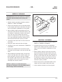
This manual is for daily users of the equipment. Always read the
Safety Instruction Manual part No 21741 before starting up the equipment
and keep the manuals with the machine for reference at all times.
Edition B, November 2000
This manual has part No 51147-GB-A
1250
125/49
- GB -
FILM PROCESSOR
GENERAL INFORMATION
This manual is published by:
Glunz & Jensen A/S
13 - 15 Haslevvej, DK - 4100 Ringsted, Denmark
Phone:
45 5768-8181
Fax:
45 5768-8340
Glunz & Jensen Inc.
21405 Airpark Drive, P.O. Box 97, Elkwood, Virginia 22718, USA
Phone:
1 540-825-7300
Fax:
1 540-825-7525
Copyright © 2000 by Glunz & Jensen A/S
The manual was written and illustrated using the best possible information available at the time of
publication.
Any differences between the manual and the equipment reflect improvements introduced after the
publication of the manual.
Changes, technical inaccuracies, and typographic errors will be corrected in subsequent editions.
As a part of our policy of continuous improvement, we reserve the right to alter design and specifications
without further notice.
0.2
0047
FILM PROCESSOR
- GB -
IMPORTANT!
1250
125/49
WARNINGS, CAUTIONS AND NOTES!
· Approvals: The equipment is manufactured
according to legal demands. For compliance
with the requirements the equipment is tested by
Underwriters Laboratories or other accredited
authority. Approvals will appear from the labels
attached to the name plate or the frame part of
the equipment.
Throughout the manual warnings, cautions, and
notes are written in italics on a grey background
like the example below:
· Intended use of the equipment: Development
of photographic materials as specified in chapter
1 "PROCESSING MATERIALS" in the Film
Processor Service Manual.
EXPLANATION
· Installation: It is the responsibility of the owner
and operator/s of the equipment , that the
installation is made in accordance with local
regulations, and by engineers authorized to carry
out plumbing and electrical installations.
Installation, service and repair must be performed
only by service technicians who are trained in
servicing the equipment. The installation procedure
is described in chapter 4 "INSTALLATION" in the
Film Processor Service Manual.
The manufacturer cannot be held responsible for
any damage caused by incorrect installation of
the equipment.
CAUTION! Make sure that .......
NOTE!
The operator should observe and/or act according
to the information in order to obtain the best
possible function of the equipment.
CAUTION!
The operator must observe and/or act according to
the information in order to avoid any mechanical or
electrical damage to the equipment.
WARNING!
The operator must observe/and or act according to
the information in order to avoid any personnel
injury.
· Technical data: Observe technical data from
the name plate located as specified on page 0.2
in the Film Processor Service Manual.
0047
0.3
1250
125/49
- GB -
FILM PROCESSOR
TABLE OF CONTENTS
. . . . . . . . . . . . . . . . . . . . . . . . . . . . . . . . . . . . . . . . . . . . . . . . . . . . . . . . . PAGE
GENERAL INFORMATION
0.2
IMPORTANT! . . . . . . . . . . . . . . . . . . . . . . . . . . . . . . . . . . . . . . . . . . . . . 0.3
WARNINGS, CAUTIONS AND NOTES! . . . . . . . . . . . . . . . . . . . . . . . . . . 0.3
1. FUNCTIONS AND FEATURES
1.1
GENERAL . . . . . . . . . . . . . . . . . . . . . . . . . . . . . . . . . . . . . . . . . . . . . . . . . . . 1.1
MAIN COMPONENTS OVERVIEW . . . . . . . . . . . . . . . . . . . . . . . . . . . . . . . . . 1.3
FUNCTIONAL DESCRIPTION . . . . . . . . . . . . . . . . . . . . . . . . . . . . . . . . . . . . 1.9
DEVELOPER SECTION . . . . . . . . . . . . . . . . . . . . . . . . . . . . . . . . . . . . . . 1.9
FIXER SECTION . . . . . . . . . . . . . . . . . . . . . . . . . . . . . . . . . . . . . . . . . . 1.11
THE REPLENISHMENT SYSTEM. . . . . . . . . . . . . . . . . . . . . . . . . . . . . . 1.11
WASH SECTION . . . . . . . . . . . . . . . . . . . . . . . . . . . . . . . . . . . . . . . . . 1.12
DRYER SECTION . . . . . . . . . . . . . . . . . . . . . . . . . . . . . . . . . . . . . . . . . 1.13
TRANSPORT SYSTEM . . . . . . . . . . . . . . . . . . . . . . . . . . . . . . . . . . . . . 1.14
ECOLOGICAL UNITS . . . . . . . . . . . . . . . . . . . . . . . . . . . . . . . . . . . . . . 1.14
2. OPERATING PROCEDURES
2.1
GENERAL . . . . . . . . . . . . . . . . . . . . . . . . . . . . . . . . . . . . . . . . . . . . . . . . . . . 2.1
DAILY START-UP . . . . . . . . . . . . . . . . . . . . . . . . . . . . . . . . . . . . . . . . . . . . . 2.3
MANUAL START-UP . . . . . . . . . . . . . . . . . . . . . . . . . . . . . . . . . . . . . . . 2.3
AUTOMATIC START-UP . . . . . . . . . . . . . . . . . . . . . . . . . . . . . . . . . . . . . 2.3
PROCESSING FROM THE FEED TABLE . . . . . . . . . . . . . . . . . . . . . . . . . . . . 2.5
PROCESSING FROM THE DAYLIGHT CASSETTE . . . . . . . . . . . . . . . . . . . . . 2.7
PROCESSING FROM THE DAYLIGHT SLOT . . . . . . . . . . . . . . . . . . . . . . . . . 2.9
USING THE REWASH SLOT . . . . . . . . . . . . . . . . . . . . . . . . . . . . . . . . . . . . . 2.9
SHUT-DOWN PROCEDURE. . . . . . . . . . . . . . . . . . . . . . . . . . . . . . . . . . . . . 2.11
MANUAL SHUT-DOWN . . . . . . . . . . . . . . . . . . . . . . . . . . . . . . . . . . . . 2.11
AUTOMATIC SHUT-DOWN . . . . . . . . . . . . . . . . . . . . . . . . . . . . . . . . . . 2.11
"GFCI" Ground Fault Circuit Interrupter . . . . . . . . . . . . . . . . . . . . . . . . . . . 2.13
USING THE GFCI RELAY . . . . . . . . . . . . . . . . . . . . . . . . . . . . . . . . . . . 2.13
0.4
0047
FILM PROCESSOR
- GB -
1250
125/49
TABLE OF CONTENTS
. . . . . . . . . . . . . . . . . . . . . . . . . . . . . . . . . . . . . . . . . . . . . . . . . . . . . . . . . PAGE
3. CLEANING AND MAINTENANCE
3.1
GENERAL . . . . . . . . . . . . . . . . . . . . . . . . . . . . . . . . . . . . . . . . . . . . . . . . . . . 3.1
DISASSEMBLING FOR CLEANING . . . . . . . . . . . . . . . . . . . . . . . . . . . . . . . . 3.2
DRIP TRAY . . . . . . . . . . . . . . . . . . . . . . . . . . . . . . . . . . . . . . . . . . . . . . 3.2
TOP COVER AND DRYER COVER . . . . . . . . . . . . . . . . . . . . . . . . . . . . . 3.3
HANDLING A WET RACK . . . . . . . . . . . . . . . . . . . . . . . . . . . . . . . . . . . . 3.3
REMOVING THE DRYER RACK . . . . . . . . . . . . . . . . . . . . . . . . . . . . . . . 3.4
SMALL ANTI-OXIDATION LIDS . . . . . . . . . . . . . . . . . . . . . . . . . . . . . . . . 3.5
RACK OXIDATION LIDS . . . . . . . . . . . . . . . . . . . . . . . . . . . . . . . . . . . . . 3.5
ROLLER BEARINGS . . . . . . . . . . . . . . . . . . . . . . . . . . . . . . . . . . . . . . . . 3.5
RACKS AND ROLLERS . . . . . . . . . . . . . . . . . . . . . . . . . . . . . . . . . . . . . 3.7
CROSSOVER GUIDES . . . . . . . . . . . . . . . . . . . . . . . . . . . . . . . . . . . . . . 3.7
CLEANING . . . . . . . . . . . . . . . . . . . . . . . . . . . . . . . . . . . . . . . . . . . . . . . . . . 3.8
GENERAL . . . . . . . . . . . . . . . . . . . . . . . . . . . . . . . . . . . . . . . . . . . . . . . 3.8
DAILY CLEANING . . . . . . . . . . . . . . . . . . . . . . . . . . . . . . . . . . . . . . . . . 3.8
WEEKLY CLEANING . . . . . . . . . . . . . . . . . . . . . . . . . . . . . . . . . . . . . . . 3.9
MONTHLY CLEANING . . . . . . . . . . . . . . . . . . . . . . . . . . . . . . . . . . . . . . 3.9
MAINTENANCE . . . . . . . . . . . . . . . . . . . . . . . . . . . . . . . . . . . . . . . . . . . . . . 3.10
REMOVING FILTERS . . . . . . . . . . . . . . . . . . . . . . . . . . . . . . . . . . . . . . 3.10
REPLENISHMENT . . . . . . . . . . . . . . . . . . . . . . . . . . . . . . . . . . . . . . . . . . . . 3.11
CHECK OF DEVELOPER REPLENISHMENT . . . . . . . . . . . . . . . . . . . . . 3.11
CHECK OF FIXER REPLENISHMENT . . . . . . . . . . . . . . . . . . . . . . . . . . 3.11
CHECK OF OXIDATION REPLENISHMENT . . . . . . . . . . . . . . . . . . . . . . 3.11
0047
0.5
1250
125/49
0.6
- GB -
FILM PROCESSOR
0047
FILM PROCESSOR
- GB -
1250
125/49
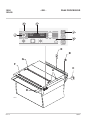
1. FUNCTIONS AND FEATURES
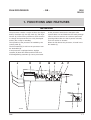
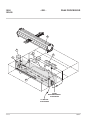
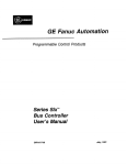
GENERAL
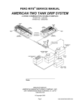
The processor contains 4 major sections (see figure
below): Developer (A), fixer (B), wash (C), and dryer
section (D). Each section performs a basic function
to change the exposed film into a fully developed
and dry film, ready for handling.
The operation of the processor is handled by the
control panel (E).
The film material (F) is fed into the processor from
the feed-table (G).
If the processor is equipped with a daylight
cassette (H) both film sheets and film rolls from
PTS/Imagesetting-cassettes (I) can be processed.
J
D
C
At the processor entrance the transport roller
system takes over and leads the film safely through
each of the four sections at a uniform speed and
special guides make sure that it passes smoothly
from one section to another.
When the film leaves the processor, it lands in the
film basket (L).
B
E
A
F
G
H
I
T1812
0047
1.1
1250
125/49
- GB -
FILM PROCESSOR
21
12
14
11
10
13
23
22
15
19
16
19
9
17
20
8
19
7
4
6
0
1
1
18
19
5
3
2
24
T1813
26
25
1.2
0047
FILM PROCESSOR
- GB -
1250
125/49
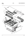
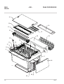
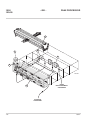
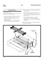
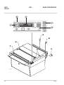
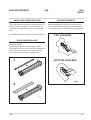
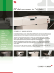
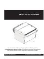
MAIN COMPONENTS OVERVIEW
(See illustration opposite)
A
MAIN SWITCH (1)
Switches the power to the processor ON/OFF.
The main switch is also a lock, and cannot be
turned on without the key delivered with the
processor.
ELECTRONICS CABINET (2)
The electronics cabinet holds the main control
electronics and the fuses for all functions.
The cabinet is fitted with a cover inside to protect
the electronics.
B
CONTROL PANEL (3)
The processor is operated from the control panel.
See description in the "FMA Control Panel" manual.
FEED TABLE (4)
As standard the processor is equipped with a feed
table.
Some models only: Alternatively the processor is
equipped with a daylight cassette (A) (see figure
opposite). The cassette is equipped with a specially
designed shelf (B) that makes it easy to handle both
small and big PTS/Imagesetting cassettes. The
shelf can also be used as a feed table.
INPUT SENSORS (5)
The processor is equipped with 7 input sensors
placed at the processor entrance. When film is
inserted, the input sensors automatically start the
processor provided that the processor is switched
on by the main switch (1) and the ON-button on the
control panel (3).
0047
T31284
DEVELOPER SECTION (6)
See detailed description in “DEVELOPER SECTION”
later in this chapter.
FIXER SECTION (7)
See detailed description in “FIXER SECTION” later
in this chapter.
WASH SECTION 1 AND 2 (8)
See detailed description in “WASH SECTION” later
in this chapter.
1.3
1250
125/49
- GB -
FILM PROCESSOR
21
12
14
11
10
13
23
22
15
19
16
19
9
17
20
8
19
7
4
6
0
1
1
18
19
5
3
2
24
T1813
26
25
1.4
0047
FILM PROCESSOR
- GB -
DRYER SECTION (9)
See detailed description in “DRYER SECTION” later
in this chapter.
1250
125/49
DEVELOPER FILTER (15)
The developer tank is equipped with a filter that
removes mechanical impurities and floating
particles from the developer solution. The filter unit
has its own circulation pump.
RACKS (10)
The racks are a combination of rollers and guides
that smoothly transport the film through the wet
sections and the dryer section of the film processor.
Roller configuration is shown in chapter 3 "RACKS,
ROLLERS AND GUIDES".
ANTI-OXIDATION LIDS (11)
The developer and fixer racks are equipped with
anti-oxidation lids. The anti-oxidation lids reduce
the oxidation from the chemical baths as well as it
minimizes build-up of condensate underneath the
condensation lids (12) and (13) and the top cover
(21).
DEV/FIX CONDENSATION LID (12)
The developer and fixer sections are equipped with
a condensation lid to prevent condensation
underneath the top cover and that fixer
condensation drips into the developer section and
opposite.
WASH CONDENSATION LID (13)
The wash sections are also equipped with a
condensation lid to prevent condensation
underneath the top cover.
FIXER FILTER (16)
Some models only.
Like the developer tank, the fixer tank also is
equipped with a filter that removes mechanical
impurities and floating particles from the developer
solution. The filter unit has its own circulation
pump.
COVER FOR FILTERS (17)
Some models only.
The filters (15) and (16) are covered with a small
cover which is easily tipped.
SCAVENGER FAN (18)
In the right tank side is mounted a fan for removal
of chemical vapours from inside of the wet
sections.
SAFETY SWITCHES (19)
The processor is equipped with 4 safety switches. If
either the top cover (22) (two switches), the dryer
cover (23), or the filters cover (17) (some models
only) are removed from the processor, the related
switch(es) will switch the processor to a safe mode.
In the safe mode pumps and moving parts cannot
be activated.
DRIP TRAY (14)
With the processor is delivered a drip tray on which
a rack can be placed and carried away for cleaning
without spilling of chemicals.
0047
WARNING! Never activate any of the safety
switches without the covers mounted as this
will make the processor start in jog mode and
activate pumps and moving parts.
1.5
1250
125/49
- GB -
FILM PROCESSOR
21
12
14
11
10
13
23
22
15
19
16
19
9
17
20
8
19
7
4
6
0
1
1
18
19
5
3
2
24
T1813
26
25
1.6
0047
FILM PROCESSOR
- GB -
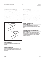
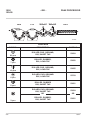
OVERFLOW/DRAIN TUBE (20)
Each bath is equipped with a combined overflow
and drain tube in the right-hand side of the tank
section. In the developer section and in the fixer
section the tubes are placed underneath the top
cover. The tubes for the wash water is placed
through the top cover.
To empty the baths the tubes must be turned 90°
counterclockwise.
As shown on the figure below it is easily observed if
drain tubes for wash tanks are opened or closed.
OPEN
1250
125/49
FILM BASKET (23)
When leaving the processor the film material is
collected in the film basket.
STAND (24)
The processor is delivered with a closed stand. The
side panels of the stand are very easy to remove.
Inside the stand there is room for a large drip tray
(25) and trolleys (26) with containers for
replenishment and/or waste chemicals (optional).
LARGE DRIP TRAY (25)
Some models only.
The large drip tray fits inside the stand and is
designed specially for easy handling of the trolleys
(26).
CLOSED
TROLLEYS WITH CONTAINERS (26)
Some models only.
A pair of trolleys fit inside the stand and make it
easy to handle both replenishment containers and
containers for waste chemicals when changing,
emptying, refilling etc.
T31285
TOP COVER (21)
The top cover is fitted with two handles for easy
handling.
DRYER COVER (22)
The dryer cover covers the dryer section only and
has a cutout for film exit and holes for mounting of
film basket.
0047
1.7
1250
125/49
- GB -
FILM PROCESSOR
M
FIL
8
4
6
7
2
3
5
T31286
(F
LO
W
)
FROM
REPLENISHMENT
CONTAINER
1
TO WASTE
CONTAINER
1.8
0047
FILM PROCESSOR
- GB -
1250
125/49
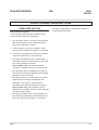
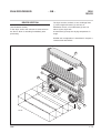
FUNCTIONAL DESCRIPTION
DEVELOPER SECTION
(See illustration opposite).
In the developer (DEV) section the latent image
created during exposure is developed.
· The developer section consists of a processing
tank with a heater (1) and a thermostat (2) to
keep the temperature constant.
The roller configuration is described in chapter 3,
"RACKS AND ROLLERS".
NOTE! Some models are equipped with special
racks for polyester plates.
See Appendix B for roller configuration for
polyester racks.
· A level detector (3) prevents operation of the
processor with insufficient amount of chemicals.
· A pump (4) recirculates the solution to maintain
a uniform temperature of the chemicals.
· The waste chemicals leave the tank through a
combined overflow and drain tube (5) and is led
to a waste chemicals container..
Some models only! The waste chemicals
container is equipped with a max. level sensor.
· The developer tank is equipped with a filter (6)
that removes mechanical impurities and floating
particles from the chemicals.
· The bellows pump (7) connected to an external
replenishment container automatically add
developer to the tank to compensate for
chemicals used during actual film processing.
Some models only: A level detector in the
replenishment container gives an alarm when the
container needs refilling.
· The rack is equipped with an anti-oxidation lid
(8) preventing condensation underneath the top
cover and minimizing oxidation of chemicals.
0047
1.9
1250
125/49
- GB -
FILM PROCESSOR
M
FIL
8
6
4
9
3
2
5
(F
LO
W
1
)
FROM
REPLENISHMENT
CONTAINER
TO WASTE
CONTAINER
1.10
0047
FILM PROCESSOR
- GB -
FIXER SECTION
(See illustration opposite).
In the fixer (FIX) section the developing process is
stopped and unexposed silver halide is dissolved.
· The fixer section consist of a processing tank
with a heater (1) and a thermostat (2) to keep the
temperature constant.
· A level detector (3) prevents operation of the
processor with insufficient amount of chemicals.
· A pump (4) recirculates the solution to maintain
a uniform temperature of the chemicals.
· The waste chemicals leaves the tank through a
combined overflow and drain tube (5) and is led
to a waste chemicals container.
Some models only! The waste chemicals
container is equipped with a max. level sensor.
1250
125/49
THE REPLENISHMENT SYSTEM
The system automatically adds developer and fixer
to compensate for chemicals used during actual
film processing.
The system also supplies additional developer to
compensate for lost activity caused by normal
oxidation.
It is possible to operate the replenishment pumps
manually (to “top up” the tank levels) on the control
panel. See also the "FMA Control Panel" manual.
Film sensors at the entrance of the processor start
the replenishment control circuit when film is
entered.
· Some models only! The fixer tank is equipped
with a filter (6) that removes mechanical
impurities and floating particles from the
chemicals.
· The bellows pump (7) connected to an external
replenishment container automatically add fixer
to the tank to compensate for chemicals used
during actual film processing.
Some models only: A level detector in the
replenishment container gives an alarm when the
container needs refilling.
· The rack is equipped with an anti-oxidation lid
(8) preventing condensation underneath the top
cover and minimizing oxidation of chemicals.
The roller configuration is described in chapter 3,
"RACKS AND ROLLERS".
0047
1.11
1250
125/49
- GB -
FILM PROCESSOR
· Water from the wash-2 section overflow to the
wash-1 section.
WASH SECTION
(See illustration below).
In the wash section (WASH) any residual chemicals
are washed off the film material.
· A level detector (3) prevents operation of the
processor with insufficient amount of water. The
wash section will automatically be topped up if
low level occurs.
· When the processor is switched on fresh water
is added to the WASH 2 section from an
external water supply controlled by a water
solenoid valve (1), or
some models only: ... from the water supply
container controlled by a bellows pump (2).
· The wash water overflows into combined
overflow/- drain tubes (4) which are located
through the top cover (see “MAIN COMPONENTS
OVERVIEW”).
WASH rack configuration is described in chapter 3,
“RACKS AND ROLLERS”.
M
FIL
EXTERNAL WATER
SUPPLY
3
)
W
O
FL
(
2
1
H
S
A
W
2
A
W
1
H
S
4
FROM
WATER SUPPLY
CONTAINER
T31289
TO WASTE
CONTAINER
1.12
0047
FILM PROCESSOR
- GB -
DRYER SECTION
(See illustration below).
In the dryer section the moisture is removed from
the film to allow for handling immediately after
processing.
1250
125/49
The dryer section consists of two centrifugal fans
(1) with integrated heaters (2) and two air
distribution boxes, one underneath (3) and one
above (4) the dryer rack.
A thermostat (5) keeps the drying temperature in
range.
DRYER rack configuration is described in chapter 3,
“RACKS AND ROLLERS”.
FI
LM
4
5
2
1
3
2
1
T31290
0047
1.13
1250
125/49
- GB -
TRANSPORT SYSTEM
The transport system consists of a main
drive-motor connected to a worm gear drive
system. The drive system turns the rollers in each
rack which, in conjunction with the film guides and
crossovers, directs the film through the processor.
FILM PROCESSOR
ECOLOGICAL UNITS
The processor is prepared for connections to
ecological units for the developer, fixer, and wash
sections, and chemical vapours exhaust.
Ask your local dealer for more information about the
ecological units and chemical vapours exhaust kit.
Squeegee rollers at the entrance of the dryer
section remove surface moisture from the film and
divert water to the wash section.
The illustration in chapter 3 "RACKS AND
ROLLERS" shows positions of rollers and guides in
each rack.
1.14
0047
FILM PROCESSOR
- GB -
1250
125/49
2. OPERATING PROCEDURES
GENERAL
Procedures for daily operation of the processor are
described on the following pages.
0047
2.1
1250
125/49
- GB -
4
FILM PROCESSOR
2
P
PROG 2
TIMER
1
3
1-4
READY
MENU
5
DEV
FIX
E
OF
F
B
ON
G
F
A
C
0
1
D
T1840
2.2
0047
FILM PROCESSOR
- GB -
1250
125/49
DAILY START-UP
(See illustration opposite)
MANUAL START-UP
· Before starting up the processor follow the
procedure for daily cleaning as described in
chapter 3.
AUTOMATIC START-UP
The auto-start function enables automatic start-up
and shut-down of the processor.
The auto-start function is described in the "FMA
Control Panel" manual: "STARTING THE
PROCESSOR" and "AUTO MODE".
· Make certain that the wash tank drain tubes (A)
are closed (see fig.).
· Open external water supply valve (B).
· If the processor is turned off on the main
switch (no indicators on the control panel are
lit):
- Models with GFCI relay only:
Activate the reset button/switch on the GFCI
relay. The indicator on the GFCI will turn red
or light up depending on which model is
installed. (See also "GFCI RELAY" later in this
chapter).
- Turn the main switch (C) to ON/I.
The "power on" indicator (4) is lit and the
display (2) shows "Initializing, Please wait...".
US models with GFCI relay only:
Activate the reset button on the GFCI relay. The
red indicator on the GFCI relay will light up.
(See also "GFCI RELAY" later in this chapter).
· When the processor is in off mode the power on
indicator (5) is lit and the display (2) is black.
Press the stand-by key (1) on the control panel.
The processor turns into stand-by mode and the
display (2) will show the latest employed
program. See the "FMA Control Panel" manual
for more information about the control panel
functions and operation.
· When the processor is switched to stand-by
mode the wash section is filled up automatically.
· Feed some sheets of film through the processor
to clean it.
· Your processor is now ready for processing.
· Shut-down is described later in this chapter.
0047
2.3
1250
125/49
- GB -
4
FILM PROCESSOR
2
P
PROG 2
TIMER
1
3
1-4
READY
MENU
5
DEV
FIX
E
OF
F
B
ON
G
F
A
C
0
1
D
T1840
2.4
0047
FILM PROCESSOR
- GB -
1250
125/49
PROCESSING FROM THE FEED TABLE
(See illustration opposite).
· Select the program suitable for the processing
material by means of the program key (3). The
display (2) shows which program is active at any
time.
· Slowly enter the film (with the emulsion side up)
into the processor using the film feed guide (D)
until it engages the drive system. Activating the
input sensors the processor will start at the
speed specified in the selected program.
· Verify that the display (2) changes between the
messages "PROCESSING" and "WAIT PRC".
When the message "WAIT PRC" disappears you
can insert another film.
· When the film exits, the display returns to
stand-by mode.
0047
2.5
1250
125/49
- GB -
4
FILM PROCESSOR
2
P
PROG 2
TIMER
1
3
1-4
READY
MENU
5
DEV
FIX
E
OF
F
B
ON
G
F
A
C
0
1
D
T1840
2.6
0047
FILM PROCESSOR
- GB -
1250
125/49
PROCESSING FROM THE DAYLIGHT CASSETTE
(See also figure to the right).
· Verify that the processor is not busy (display (2)
messages change between "PROCESSING" and
"WAIT PRC" when busy). When the message
"WAIT PRC" disappears you can insert another
film.
6
8
· Open the cassette cover (5).
· Adjust the shelf (6) to fit the cassette size or
remove it, whatever is necessary.
· Select processing program by means of the
program key (3). The display (2) shows which
program is active at any time.
· Place the cassette (7) on the shelf and enter the
film/paper (8) into the processor until it engages
the drive system. The input roller ensures that
the material enters the processor without
scratches. When the input sensors are activated,
the processor starts and the display (2) shows
"PROCESSING".
7
T1846
5
· Close the cassette cover (5) and do not open
until the message "WAIT PRC" in the display
disappears.
· When the message "WAIT PRC" disappears the
processor is ready to process another cassette.
The shelf can also be used as feed table. In that
case adjust the shelf to upper position and follow
the procedure described in “PROCESSING FROM
THE FEED TABLE”. Feed paper between the white
marks on the shelf.
0047
2.7
1250
125/49
- GB -
4
FILM PROCESSOR
2
P
PROG 2
TIMER
1
3
1-4
READY
MENU
5
DEV
FIX
E
OF
F
B
ON
G
F
A
C
0
1
D
T1840
2.8
0047
FILM PROCESSOR
- GB -
1250
125/49
PROCESSING FROM THE DAYLIGHT SLOT
(See illustration opposite).
NOTE! Some models only.
· Verify that the processor is not busy.
· Open the daylight slot (F). The messages in the
display (2) change between "PROCESSING" and
"WAIT PRC".
· Feed paper into the processor and close the
daylight slot.
· When the message "WAIT PRC" disappears
from the display, the processor is ready to
receive another film through the daylight slot.
USING THE REWASH SLOT
(See illustration opposite).
NOTE! Some models only.
· Verify that the processor is not busy.
· Open the rewash slot (G). The messages in the
display (2) change between "PROCESSING" and
"WAIT PRC".
· Feed paper into the processor and close the
rewash slot.
· When the message "WAIT PRC" disappears
from the display, the processor is ready to
receive another film through the rewash slot.
0047
2.9
1250
125/49
- GB -
4
FILM PROCESSOR
2
P
PROG 2
TIMER
1
3
1-4
READY
MENU
5
DEV
FIX
E
OF
F
B
ON
G
F
A
C
0
1
D
T1840
2.10
0047
FILM PROCESSOR
- GB -
1250
125/49
SHUT-DOWN PROCEDURE
(See illustration opposite).
MANUAL SHUT-DOWN
· Push the stand-by key (1). The processor turns
into off mode: The power on indicator (4) is lit
and the display (2) is black.
The exhaust fan and the time-replenishment
circuits will still work.
AUTOMATIC SHUT-DOWN
The auto-start function enables automatic start-up
and shut-down of the processor.
The auto-start function is described in the "FMA
Control Panel" manual: "STARTING THE
PROCESSOR" and "AUTO MODE".
· Close the external water supply valve (B).
· Open the wash tank drain tubes (A) by turning
them 90° counterclockwise.
NOTE! It is recommended to drain the wash
tank at least once every 24 hours to prevent
growth of algae and thereby consequent
reduction in processing quality.
NOTE! The wash tank will be filled again
automatically when the processor is switched
to stand-by mode.
· Do not turn the main switch off ("0") during the
night, if:
- Time-replenishment is wanted.
- Removal of exhaust is wanted
- Automatic start-up is wanted.
0047
2.11
1250
125/49
- GB -
4
FILM PROCESSOR
2
P
PROG 2
TIMER
1
3
1-4
READY
MENU
5
DEV
FIX
E
OF
F
B
ON
G
F
A
C
0
1
D
T1840
2.12
0047
FILM PROCESSOR
- GB -
1250
125/49
"GFCI" Ground Fault Circuit Interrupter
Some models only!
USING THE GFCI RELAY
The processor should be started as described in
"DAILY START-UP" earlier in this chapter.
In "power off" situations the GFCI must be
operated as follows (see also figure below):
CURRENT LEAKAGE
· GFCI relay will switch power off and the red
indicator (Z) will turn off.
· Turn main switch (C) off (= 0).
· Press the reset button (X). GFCI relay will
reconnect power to the processor.
· Turn the main switch (C) on (= I).
X
Y
Z
CAUTION! If GFCI relay do not reconnect
power to the processor call service technician.
TEST BUTTON (Y)
T2311xy
The test button (Y) is for testing reliability of the
GFCI relay. Make a test approx. once a year:
· Press the test button (Y). The GFCI relay must
cut power off (red indicator (Z) turns off).
POWER SUPPLY DISCONNECTED
AT WALL SOCKET
CAUTION! If GFCI relay do not cut power off
(red indicator (Z) turns off) the GFCI relay must
be changed. Call service technician.
· Make sure that main switch (C) is off (= 0).
· If test of GFCI has been successful turn main
switch (C) off (= 0).
· Switch main power supply on (E).
· Press the reset button (X). The red indicator (Z)
will light up.
· Turn the main switch (C) on (= I).
CAUTION! Always activate the RESET button
(X) each time the main power supply is
switched on.
CAUTION! Never use the TEST button (Y) on the
GFCI relay as power-off switch.
0047
· Press the reset button (X). The GFCI relay will
reconnect power to the processor. The red
indicator (Z) will light up.
· Turn main switch (C) on (= I).
SEE ALSO DESCRIPTION OF GFCI RELAY ON
THE NEXT PAGE.
2.13
1250
125/49
- GB -
4
FILM PROCESSOR
2
P
PROG 2
TIMER
1
3
1-4
READY
MENU
5
DEV
FIX
E
OF
F
B
ON
G
F
A
C
0
1
D
T1840
2.14
0047
FILM PROCESSOR
- GB -
1250
125/49
"GFCI" Ground Fault Circuit Interrupter
Some models only!
USING THE GFCI RELAY
CURRENT LEAKAGE
The processor should be started as described in
"DAILY START-UP" earlier in this chapter.
In "power off" situations the GFCI must be
operated as follows (see also figure below):
Z
Y
· GFCI relay will switch power off and the
indicator (Z) will turn green.
· Turn main switch (J) off.
· Push the reset switch (X) upwards. The indicator
will turn red and the GFCI relay reconnects
power to the processor.
· Turn the main switch (J) on.
X
CAUTION! If GFCI relay do not reconnect
power to the processor call service technician.
TEST BUTTON (Y)
Leuc
hten
fest
T2475
03-A
0/ 4 /0
F7- 4
POWER SUPPLY DISCONNECTED
AT WALL SOCKET
· Switch main power supply on (H).
· Make sure that main switch (J) is off.
The test button (Y) is for testing reliability of the
GFCI relay. Make a test approx. once a year:
· Press the test button (Y). The GFCI relay must
cut power off (indicator (Z) must turn green).
CAUTION! If GFCI relay do not cut power off
(indicator (Z) does not turn green) the GFCI
relay must be changed. Call service technician.
· If test of GFCI has been successful turn main
switch (J) off.
· Push the reset switch (X) upwards. The
indicator (Z) will turn red.
· Push the reset switch (X) upwards. The GFCI
relay will reconnect power to the processor. The
indicator (Z) will turn red.
· Turn the main switch (J) on.
· Turn main switch (J) on.
CAUTION! Never use the TEST button (Y) on the
GFCI relay as power-off switch.
0047
SEE ALSO DESCRIPTION OF GFCI RELAY ON
THE PREVIOUS PAGE.
2.15
1250
125/49
2.16
- GB -
FILM PROCESSOR
0047
FILM PROCESSOR
- GB -
1250
125/49
3. CLEANING AND MAINTENANCE
GENERAL
Performing maintenance on a scheduled basis
reduces the possibilities of equipment failure and
the loss of processing quality. Only one person
should be responsible for performing the preventive
maintenance program. That person should be
familiar with the equipment as well as its
operational characteristics and maintenance
requirements.
A periodic major clean-up of the equipment is
important to maintain the processing quality and
reliability of the processor.
This clean-up should be performed either monthly
or after processing approx. 1000m2 (10.000 ft2) of
film.
NOTE! Before attempting any maintenance or
clean-up procedures the personnel must
familiarize themselves with the safety
instructions and environmental protection
described in the SAFETY INSTRUCTIONS
MANUAL delivered with the processor.
WARNING! BE SURE TO DISCONNECT
ELECTRICAL POWER BEFORE
PERFORMING ANY CLEANING OR
MAINTENANCE.
The major clean-up procedure can be performed in
2 to 4 hours depending on the condition of the
processor and on the proficiency of the person
cleaning it.
0047
3.1
1250
125/49
- GB -
FILM PROCESSOR
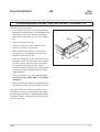
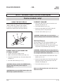
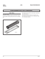
DISASSEMBLING FOR CLEANING
DRIP TRAY
(See figure below).
A drip tray is delivered with the processor. Use the
drip tray when carrying away the racks for cleaning
etc.
The drip tray has catches in each side in which the
rack side plates fit.
Press the rack down between the catches (see
figure below) and carry away for cleaning by lifting
in the side plate handles.
T31270
3.2
0047
FILM PROCESSOR
- GB -
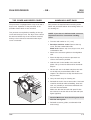
TOP COVER AND DRYER COVER
The processor is equipped with a top cover and a
dryer cover. Operation of the processor is not
possible without both covers mounted.
Two persons are required for handling of the top
cover and the dryer cover. The dryer cover cannot
be removed unless top cover has been removed,
and top cover cannot be mounted unless dryer
cover is mounted.
1250
125/49
HANDLING A WET RACK
Two persons are required when removing racks.
Follow the procedure below when taking racks out
for cleaning etc.
NOTE! If processor is delivered with crane see
separate manual for crane when handling
racks.
· Turn the main switch to "0" (= off).
· Developer and fixer racks: Remove the top
cover, and the condensation lids.
Wash rack: Remove top cover, dryer cover, and
condensation lids.
· Remove the crossover guide on the neighbour
rack.
· Place the drip tray across the processor as
close to the bath as possible.
· Grab the rack in the handle of the rack side
plates. Lift up in the left side and let chemicals
drip off.
· Lift the rack out of the bath and place the rack
on the drip tray as described earlier in this
chapter. Be careful not to drip chemicals onto
the processor.
· Carry the rack away for cleaning etc.
· Reinstall the rack in the reverse order. If the bath
contains chemicals while reinstalling, lower the
rack very carefully to avoid that chemicals flow
over into the other baths.
Make sure that the left rack side panel fit into
the notches in the left side of the tank wall (see
figure opposite).
T31268
Caution! Make sure that the drive gears mesh
with the worm gears.
· Reinstall crossover guides, condensation lids
and cover(s).
0047
3.3
1250
125/49
- GB -
FILM PROCESSOR
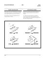
REMOVING THE DRYER RACK
Two persons are required when removing top cover
and dryer rack. Follow the procedure below when
taking the dryer rack out for cleaning etc.
B
A
1
See figure opposite.
· Turn the main switch to "0" (= off).
· Remove top cover and dryer cover.
· Remove crossover guide between wash rack
and dryer rack.
· Stand at the rear end of the processor. One
person in each side.
· Fig. 1: Remove the upper dryer cassette (A) by
lifting it up, out of the air flanges (B) in each side
of the dryer section.
· Fig. 2: Grab in the dryer rack side plates and
pull the dryer rack (C) upwards in order to
release the bearings from the drive shaft, and lift
it out of the processor.
C
2
CAUTION! Always lift the rack in the side
plates.
· After cleaning, it is very important that the rack
is reinstalled correctly. Make sure that bearings
catch the drive shaft and the drive gears mesh
with the worm gears.
T31296
· Reinstall upper dryer cassette (A), crossover
guide, dryer cover and top cover.
3.4
0047
FILM PROCESSOR
- GB -
1250
125/49
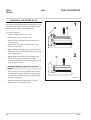
SMALL ANTI-OXIDATION LIDS
ROLLER BEARINGS
In the right side of the developer and fixer bath is a
small lid which is installed to prevent oxidation of
chemicals. The small lid has a cut-out for the drain
tube.
When reinstalling the roller pairs in the racks, be
very careful that the bearings are locked properly in
the respective slots as indicated in the figure below.
The small lid is easily removed by pulling upwards.
TOP ROLLERS
RACK OXIDATION LIDS
(See figure below)
The developer and fixer rack is equipped with
anti-oxidation lids. To remove the anti-oxidation lids
first remove the roller pair in the exit part of the
rack (1) then lift out the anti-oxidation lid (2).
1
BOTTOM ROLLERS
T 3298
2
T31272
0047
3.5
1250
125/49
- GB -
DEV
FIX
WASH1 WASH2
FILM PROCESSOR
DRY
T31297
ROLLERS
SYMBOL
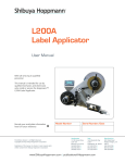
23 pcs
7 pcs
13 pcs
2 pcs
5 pcs
DESCRIPTION
PART NO
ROLLER, PUR, GROUND,
D30, SHORT TAP
53254
ROLLER, RUBBER,
D30, LONG TAP
53250
ROLLER, PUR, GROUND,
D30, LONG TAP
53255
ROLLER, PUR, GROUND
D30, LONG TAP
53703
ROLLER, RUBBER
D30, SHORT TAP
53251
ROLLER, PUR, GROUND
D30, SHORT TAP
OR
3 pcs
3.6
ROLLER, RUBBER,
D30, SHORT TAP
53254
OR
53251
0047
FILM PROCESSOR
- GB -
RACKS AND ROLLERS
1250
125/49
CROSSOVER GUIDES
When racks have been disassembled for cleaning
or servicing purposes it is very important that the
rollers are reinstalled in their correct positions.
Between each section are mounted crossover
guides for guiding the film from one section to
another.
See illustration opposite for identification and
correct position of rollers.
The illustration opposite shows the type, part No
and correct position of each roller in the processor.
It is important that the guides are installed in
correct places and for easy identification each
guide is marked with small holes in the right side of
the guide. See figure below.
T31336
DEV
FIX
0047
FIX
WASH1
WASH2
WASH1
WASH2
DRYER
3.7
1250
125/49
- GB -
FILM PROCESSOR
CLEANING
GENERAL
DAILY CLEANING
When using water for cleaning purposes, use warm
water 35 - 40°C (95 - 104°F).
It is recommended to clean the processor each day
before you start processing. Follow the procedure
below:
MORNING:
· Remove top cover, dryer cover and
condensation lids. Two persons are required for
removal of the top cover.
· Clean top rollers and crossover guides with a
moist cloth.
Do not use abrasive materials on the processor.
· Clean feed table with a moist cloth.
· Reinstall condensation lids, dryer cover, and top
cover.
· Check the level in both replenishment containers
and refill if needed.
· Empty the waste-chemicals tanks.
EVENING:
· Drain the wash tanks and close the drain-tubes
at the end of each shift.
CAUTION! Never cover the processor with a
cloth or piece of plastic to protect it from dust,
as this prevents free circulation around the
processor and can lead to overheating and
increased condensation.
3.8
0047
FILM PROCESSOR
- GB -
1250
125/49
WEEKLY CLEANING
CAUTION! Never use any hard tool or abrasive
materials when handling and cleaning the
rollers.
· Weekly cleaning procedure should be made in
addition to "DAILY CLEANING".
· Remove the developer rack as described earlier
in this chapter and rinse it with water. Be sure to
rinse off possible crystallization on film guides.
· When needed, empty the developer tank and
clean both tank and rack with tank-cleaner. Ask
your dealer of chemicals for advice. Be careful
not to get any of this cleaner into the fixer
section. It is important to get all of the cleaner
out of the developer tank after cleaning and to
rinse both tank and rack in plenty of water.
· Carefully lift the wash racks out and rinse them
with water.
· Empty the wash tanks and clear off algae.
· Cleaning of fixer rack is described in “MONTHLY
CLEANING”.
· Remove the oxidation lids from all three racks,
see earlier in this chapter, and rinse the lids with
water.
· When refilling the developer tank, use the level
mark in the right side of the tank as guide, see
figure opposite. Lower the rack very carefully
into the bath, right side first in order to allow for
air bobbles to flow up. Be careful not to get
developer into the fixer section.
NOTE! If tanks are not filled before the
processor is turned on, the auto-filling feature
will fill empty tanks automatically.
0047
T31181
MONTHLY CLEANING
· Monthly cleaning procedure should be made in
addition to "WEEKLY CLEANING".
· Carefully lift the fixer rack out as described
earlier in this chapter and rinse it with water. Be
sure to rinse off possible crystallization on film
guides.
· When needed, empty the fixer tank and clean
both tank and rack with tank-cleaner. Ask your
dealer of chemicals for advice. Be careful not to
get any of this cleaner into the other sections. It
is important to get all of the cleaner out of the
fixer tank after cleaning and to rinse both tank
and rack in plenty of water.
· Remove dryer rack as described earlier in this
chapter and rinse rubber rollers with water.
· Clean residual chemicals off all worm gears.
3.9
1250
125/49
- GB -
FILM PROCESSOR
MAINTENANCE
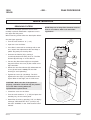
REMOVING FILTERS
The filter for developer (and fixer too on some
models) is placed underneath a separate cover in
the upper left side panel.
When removing a filter follow the description below.
NOTE! Disposal of dirty filter elements must be
done in accordance with local authorities
regulations.
See the figure opposite.
· Turn the main switch to "0" (= off).
C
· Open the cover for filters.
· If the filter is removed for exchange with a new
one, unpack the replacement filter and keep a
plastic bag ready for the dirty filter.
· Unscrew the filter lid (A) by turning it
counterclockwise and slowly lift it off. The filter
element (B) will hang on to the filter lid.
· Put the dirty filter element (B) into the plastic
bag and remove the cover (A). Be careful not to
drip chemicals.
FF
O
O
N
A
B
· Mount the new filter element (B) underneath the
cover (A) and lower it slowly into the filter
housing to avoid splashing.
· Tighten the cover (A) (clockwise). The lid is
tightened in two steps (C) as illustrated on the
figure. When it feels tight, turn it a little more.
CAUTION! Make sure the lid is tightened
properly, otherwise chemicals may be pressed
out of the filter housing when the
replenishment system starts.
· Closed the cover for the filters.
· Turn the main switch to "I" (= ON) and press the
stand-by key on the control panel.
· Reset filter account by pressing "OK" on display
message "REPLACE DEV FILT" (or FIX) if any.
See also "ALARMS" in the "FMA Control Panel"
manual.
3.10
T31137
0047
FILM PROCESSOR
- GB -
1250
125/49
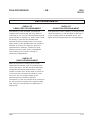
REPLENISHMENT
CHECK OF
DEVELOPER REPLENISHMENT
CHECK OF
OXIDATION REPLENISHMENT
The efficiency of the developer can either be
checked with a testing strip (ask your dealer of
chemicals) or you can use a well exposed and well
processed film as reference. If, after a week's work,
the density of your film has decreased the
replenishment has probably been too low and a
higher setting of the replenishment rate should be
selected. If, however, the density is good, the
replenishment is sufficient. If desired, a lower
setting can then be tried, until it is established
which setting of the control is enough for
satisfactory replenishment.
If the processor is left in stand by for longer periods
check the efficiency of the developer at the start of
a new working period as described above, and
adjust the time replenishment rate correspondingly.
CHECK OF
FIXER REPLENISHMENT
While the processor is working at its normal
temperature and speed, feed an unexposed film
into the processor. The film should be absolutely
transparent and without whitish spots or areas
spread at random over the film when it comes out
of the processor, otherwise the efficiency of the
fixer is too low and a higher setting of the
replenishment rate should be selected.
The efficiency of the fixer and the silver contents of
the fixer can also be tested with a special testing
strip. Ask your local specialist for application of
testing strip.
0047
3.11
1250
125/49
3.12
- GB -
FILM PROCESSOR
0047