1
SERVICE MANUAL
MODEL TYPE: YS1092
DH40H
WEB ACCESS: http://www.yorkville.com
WORLD HEADQUARTERS
CANADA
•IRONHORSE•
U.S.A.
Yorkville Sound
Yorkville Sound Inc.
550 Granite Court
Pickering, Ontario
L1W-3Y8 CANADA
4625 Witmer Industrial Estate
Niagara Falls, New York
14305 USA
Voice: (905) 837-8481
Fax: (905) 837-8746
Voice: (716) 297-2920
Fax: (716) 297-3689
Quality and Innovation Since 1963
Printed in Canada
Manual-Service-DH40H-00-1v1.pdf
IMPORTANT SAFETY INSTRUCTIONS
This lightning flash with arrowhead symbol, within
an equilateral triangle, is intended to alert the user to
the presence of uninsulated “dangerous voltage”
within the product’s enclosure that may be of sufficient
magnitude to constitute a risk of electric shock to persons.
The exclamation point within an equilatereal triangle is
intended to alert the user to the presence of important
operating and maintenance (servicing) instructions in
the literature accompanying the appliance.
Le point d’exclamation à l’intérieur d’un triangle équilatéral
est prévu pour alerter l’utilisateur de la présence
d’instructions importantes dans la littérature accompagnant l’appareil en ce qui concerne l’opération et la
maintenance de cet appareil.
Ce symbole d’éclair avec tête de flèche dans un triangle
équilatéral est prévu pour alerter l’utilisateur de la présence d’un
« voltage dangereux » non-isolé à proximité de l’enceinte du
produit qui pourrait être d’ampleur suffisante pour présenter
un risque de choque électrique.
S2125A
FOLLOW ALL INSTRUCTIONS
Instructions pertaining to a risk of fire,
electric shock, or injury to a person
SUIVEZ TOUTES LES INSTRUCTIONS
Instructions relatives au risque de feu,
choc électrique, ou blessures aux personnes
CAUTION: TO REDUCE THE RISK OF ELECTRIC
SHOCK, DO NOT REMOVE COVER (OR BACK).
AVIS: AFIN DE REDUIRE LES RISQUE DE CHOC ELECTRIQUE,
N’ENLEVEZ PAS LE COUVERT (OU LE PANNEAU ARRIERE)
NO USER SERVICEABLE PARTS INSIDE.
NE CONTIENT AUCUNE PIECE REPARABLE PAR L’UTILISATEUR.
REFER SERVICING TO QUALIFIED SERVICE PERSONNEL.
CONSULTEZ UN TECHNICIEN QUALIFIE POUR L’ENTRETIENT
THIS DEVICE IS FOR INDOOR USE ONLY!
CE PRODUIT EST POUR L’USAGE À L’INTÉREUR SEULEMENT
Read Instructions: The Owner’s Manual should be read and understood before operation
of your unit. Please, save these instructions for future reference and heed all warnings.
Veuillez Lire le Manuel: Il contient des informations qui devraient êtres comprises avant
l’opération de votre appareil. Conservez. Gardez S.V.P. ces instructions pour consultations
ultérieures et observez tous les avertissements.
Clean only with dry cloth.
Packaging: Keep the box and packaging materials, in case the unit needs to be
returned for service.
Nettoyez seulement avec le tissu sec.
Emballage: Conservez la boite au cas ou l’appareil devait être retourner pour réparation.
Warning: To reduce the risk or fire or electric shock, do not expose this apparatus to rain or
moisture. Do not use this apparatus near water!
Avertissement: Pour réduire le risque de feu ou la décharge électrique, n'exposez pas
cet appareil à la pluie ou à l'humidité. N’utilisez pas cet appareil près de l’eau!
Warning: When using electric products, basic precautions should always be followed,
including the following:
Attention: Lors de l’utilisation de produits électrique, assurez-vous d’adhérer à des
précautions de bases incluant celle qui suivent:
Power Sources
Your unit should be connected to a power source only of the voltage specified in the
owners manual or as marked on the unit. This unit has a polarized plug. Do not use
with an extension cord or receptacle unless the plug can be fully inserted. Precautions should be taken so that the grounding scheme on the unit is not defeated. An
apparatus with CLASS I construction shall be connected to a Mains socket outlet with
a protective earthing ground. Where the MAINS plug or an appliance coupler is used
as the disconnect device, the disconnect device shall remain readily operable.
Hazards
Do not place this product on an unstable cart, stand, tripod, bracket or table. The
product may fall, causing serious personal injury and serious damage to the product.
Use only with cart, stand, tripod, bracket, or table recommended by the manufacturer
or sold with the product. Follow the manufacturer’s instructions when installing the
product and use mounting accessories recommended by the manufacturer. Only use
attachments/accessories specified by the manufacturer
Note: Prolonged use of headphones at a high volume may cause
health damage on your ears.
The apparatus should not be exposed to dripping or splashing water; no objects
filled with liquids should be placed on the apparatus.
Terminals marked with the “lightning bolt” are hazardous live; the external wiring
connected to these terminals require installation by an instructed person or the use of
ready made leads or cords.
Ensure that proper ventilation is provided around the appliance. Do not install near
any heat sources such as radiators, heat registers, stoves, or other apparatus
(including amplifiers) that produce heat.
No naked flame sources, such as lighted candles, should be placed on the apparatus.
Power Cord
Do not defeat the safety purpose of the polarized or grounding-type plug. A polarized plug
has two blades with one wider than the other. A grounding type plug has two blades and a
third grounding prong. The wide blade or the third prong are provided for your safety. If the
provided plug does not fit into your outlet, consult an electrician for replacement of the
obsolete outlet. The AC supply cord should be routed so that it is unlikely that it will be
damaged. Protect the power cord from being walked on or pinched particularly at plugs. If
the AC supply cord is damaged DO NOT OPERATE THE UNIT. To completely disconnect
this apparatus from the AC Mains, disconnect the power supply cord plug from the AC
receptacle. The mains plug of the power supply cord shall remain readily operable.
Unplug this apparatus during lightning storms or when unused for long periods of time.
Service
The unit should be serviced only by qualified service personnel. Servicing is required
when the apparatus has been damaged in any way, such as power-supply cord or plug is
damaged, liquid has been spilled or objects have fallen into the apparatus, the apparatus
has been exposed to rain or moisture, does not operate normally, or has been dropped.
Alimentation
L’appareil ne doit être branché qu’à une source d’alimentation correspondant au
voltage spécifié dans le manuel ou tel qu’indiqué sur l’appareil. Cet appareil est équipé
d’une prise d’alimentation polarisée. Ne pas utiliser cet appareil avec un cordon de
raccordement à moins qu’il soit possible d’insérer complètement les trois lames. Des
précautions doivent êtres prises afin d’eviter que le système de mise à la terre de
l’appareil ne soit désengagé. Un appareil construit selon les normes de CLASS I
devrait être raccordé à une prise murale d’alimentation avec connexion intacte de mise
à la masse. Lorsqu’une prise de branchement ou un coupleur d'appareils est utilisée
comme dispositif de débranchement, ce dispositif de débranchement devra demeurer
pleinement fonctionnel avec raccordement à la masse.
Risque
Ne pas placer cet appareil sur un chariot, un support, un trépied ou une table instables.
L’appareil pourrait tomber et blesser quelqu’un ou subir des dommages importants.
Utiliser seulement un chariot, un support, un trépied ou une table recommandés par le
fabricant ou vendus avec le produit. Suivre les instructions du fabricant pour installer
l’appareil et utiliser les accessoires recommandés par le fabricant. Utilisez seulement
les attachements/accessoires indiqués par le fabricant
Note: L'utilisation prolongée des écouteurs à un volume élevé peut
avoir des conséquences néfastes sur la santé sur vos oreilles. .
Il convient de ne pas placer sur l’appareil de sources de flammes nues, telles que
des bougies allumées.
L’appeil ne doit pas être exposé à des égouttements d’eau ou des éclaboussures
et qu’aucun objet rempli de liquide tel que des vases ne doit être placé sur l’appareil.
Assurez que lappareil est fourni de la propre ventilation. Ne procédez pas à
l’installation près de source de chaleur tels que radiateurs, registre de chaleur, fours
ou autres appareils (incluant les amplificateurs) qui produisent de la chaleur.
Les dispositifs marqués d’une symbole “d’éclair” sont des parties dangereuses
au toucher et que les câblages extérieurs connectés à ces dispositifs de
connection extérieure doivent être effectivés par un opérateur formé ou en utilisant
des cordons déjà préparés.
Cordon d’Alimentation
Ne pas enlever le dispositif de sécurité sur la prise polarisée ou la prise avec tige de
mise à la masse du cordon d’alimentation. Une prise polarisée dispose de deux lames
dont une plus large que l’autre. Une prise avec tige de mise à la masse dispose de
deux lames en plus d’une troisième tige qui connecte à la masse. La lame plus large ou
la tige de mise à la masse est prévu pour votre sécurité. La prise murale est désuète si
elle n’est pas conçue pour accepter ce type de prise avec dispositif de sécurité. Dans
ce cas, contactez un électricien pour faire remplacer la prise murale. Évitez
d’endommager le cordon d’alimentation. Protégez le cordon d’alimentation. Assurezvous qu’on ne marche pas dessus et qu’on ne le pince pas en particulier aux prises.
N’UTILISEZ PAS L’APPAREIL si le cordon d’alimentation est endommagé. Pour
débrancher complètement cet appareil de l’alimentation CA principale, déconnectez le
cordon d’alimentation de la prise d’alimentation murale. Le cordon d’alimentation du
bloc d’alimentation de l’appareil doit demeurer pleinement fonctionnel.
Débranchez cet appareil durant les orages ou si inutilisé pendant de longues périodes.
Service
Consultez un technicien qualifié pour l’entretien de votre appareil. L'entretien est
nécessaire quand l'appareil a été endommagé de quelque façon que se soit. Par exemple
si le cordon d’alimentation ou la prise du cordon sont endommagés, si il y a eu du liquide
qui a été renversé à l’intérieur ou des objets sont tombés dans l'appareil, si l'appareil a été
exposé à la pluie ou à l'humidité, si il ne fonctionne pas normalement, ou a été échappé.
safety-4v8 • April 14/2011
A
B
C
D
E
F
G
H
I
J
K
L
M
N
O
P
Q
3696
R4
100K
{Function}
Val
V2:A
100N
C38
63V
Bass
22U
C28
50V
.
M
500K P2:A
1B 4444
.
C10
3N3
Gold Gold Gold
100V
R15
1M
R19
1K54
.
.
22U
C6
50V
R22
1/4W
100K
T
Q1
5101
C27
1U
63V
.
R39
15K
R72
2K2
.
.
R
J5
Poweramp In
S
S
R
3
T
J2
63V
TO92
R41
15K
Gold Gold Gold
BC550C
.
R46
1/4W
680R
1U
C40
2N2
C42
400V
63V
Preamp Out
.
R59
1M
1/4W
1/4W
R35
1K54
R40
15K
.
.
1/4W
2X_TRIODE_HCT
{Body}
.
R23
100K
1/4W
R33
1/4W
56K
1/4W
1N5
C12
200V
3417
W1
R60
680R
10U
C39
R58
1M
.
.
.
4
Twisted
CHASSIS
W26:K 12
W26:L 12
7
7
8
8
9
9
10
10
11
11
12
12
12 W26_:E
W27_:D 4
12 W26_:F
2
2
3
3
4
4
W35:C 6
W35:D 6
W35:E 6
W35:F 6
C8
22N
4 W27:C
5
Gold Gold Gold
4 W27:D
680P
C23
100V
R34
220K
.
1
R9
82K
.
Val
V4:A
.
12 W26_:G
12 W26_:I
R36
1/4W
56K
12 W26_:J
12 W26_:L
1
2
3
3
4
4
5
5
6
6
100V
R29
1M
.
R20
1K54
R14
1/4W
10K
.
2X_TRIODE_HCT
{Body}
R11
1M
C4
100N
R38
1/4W
4148 22K
.
220P
C32
200V
R12
1M
.
D15
{Body}
2X_TRIODE_HCT
63V
6 W35_:D
C3
22N
6 W35_:E
6 W35_:F
Ribbon to LEDs/Standby
S5:B
63V
C45
10U
V3:B
Val
TRIODE
6 W35_:C
C26
10U
R7
100K
400V
6
R2
1R
Gold Gold Gold
4
XF4
Part#
WIREWND
R48
7.0W
750R
Standoff
R47
7.0W
750R
W8:B 3
2
R1
1R
V5:A
Val
.
.
S
OUT_GND
W31
7
6
BLK
1 BRN
YS# 1331M
PENTODE
{Body}
.
R
J4
Out
5
{Description}
{Hz}
3392
BLK
Standoff
WIREWND
T
GRN
2 RED
160V
TP1
R10
100K
S
.
.
R6
1/4W
1K54
R
3 BLU
.
FIXED MODE
??.?Vdc
.
T
J3
Out
TP2
R8
100K
3 W8:A
R25
2.0W
1K
{Body}
PENTODE
.
.
6 W35_:A
6 W35_:B
400V
R13
1/4W
820R
.
R5
1/4W
1K54
TRIODE
Val
V3:A
10N
C5
P4:A
M Master
1/4W
47P
C17
100V
2
100K
1B
4424
2X_TRIODE_HCT
{Body}
.
12 W26_:K
1
C2
22N
{Function}
Val
V2:B
12 W26_:H
FROM_SW
W42
400V
1/4W
W35:B 6
4 W27:B
Master Volume Ribbon
Ribbon to Pots
W35:A 6
1/4W
6
W27_:C 4
3392
YEL
.
2W
W26:J 12
5
6
W27_:B 4
12 W26_:D
4 W27:A
2W
W26:I 12
5
12 W26_:C
1
1/4W
W26:H 12
4
1
TP3
W26:G 12
3
4
W27_:A 4
1/4W
W26:F 12
3
12 W26_:B
1/4W
W26:E 12
2
R18
113K
1/4W
W26:D 12
2
To 3429 Rocker Switch
12 W26_:A
1/4W
W26:C 12
1
1/4W
W26:B 12
1
1/4W
W26:A 12
7
.
K6:A
18AWG
BLK W33
.
2
R42
330K
1/4W
18AWG
BLK W32
400V
1/4W
1/4W
Input Hi
.
C20
2N2
.
P1:A
M Gain
.
400V
R24
1/4W
330K
3696
R37
1M
C43
2N2
200V
500K
15A
4425
2X_TRIODE_HCT
{Body}
.
47P
C25
100V
18AWG
GRN W34
6
.
.
Val
V1:A
R49
1/4W
68K
RING
5
R16
470K
R32
1/4W
1K
.
C11
1B 4444 1N5
500K P3:A
M
Treble
2X_TRIODE_HCT
{Body}
100V
1/4W
J1
.
3
4
18AWG
YEL W21
C21
680P
1/4W
1/4W
400V
RING
18AWG
YEL W20
400V
.
Val
V1:B
1/4W
C29
22N
.
.
K4:A
1/4W
R44
1/4W
68K
R21
113K
1/4W
J7
6588
C30
22N
Input Lo
2
1/4W
1
1/2W
1
R50
2.0W
1K
.
3
3 W8:C
8
8
4148
D18
3696
R61
100K
.
Standby
LD2
YEL
6399
1/4W
D8
3696
1/4W
4148
10
Q3
5101
D
TO92
470N
C48
63V
R75
2K2
TO92
DPDT TOGGLE SW MINI SLDR TERM
D17
GRN
6396
10
UP: Push-Pull (Full Power)
MID: STANDBY
DOWN: Cathode Bias (Low Power)
D14
3696
R80 TO92
2K2
.
Product
K2:B
.
E
9
.
MPSA13
4148
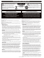
IronHorse (DH40H)
power amp
K2:A
D19
.
C
.
Q5
5101
4148
R81
1/4W
56K
B
R79
1/4W
56K
.
Q6
5103
S5:A
Single-Ended
LD3
R45
1/4W
2K2
.
4148
MPSA06
D16
R62
1K5
Q2
5105
RED
6398
SOLO
BC550C
.
.
.
400V
R68
47R
R70 TO92
2K2
1/4W
1/4W
TO92
470N
C44
63V
11
A
C47
1N
Q4
5103
BC550C
.
R71
2K2
.
MPSA06
.
S3:B
PURE
PURE
400V
R67
47R
R74
1/4W
56K
S3:A
PURE
.
.
R78
10K
1/4W
1/4W
C46
1N
1/2W
.
R66
2K
Push-Pull
LD1
R77
1/4W
1K5
K6:B
R76
10K
1/4W
Gold Gold Gold
R65
2K
1/4W
K4:B
T
1/4W
R
1/4W
S
1/2W
J6
9
Footswitch
4148
PCB# M1423
Date: Tue Feb 28, 2012 Rev: V03
Filename: M1423V03sch.sch2006
F
G
H
I
J
K
L
M
N
O
P
Sheet 1 of 3
YsType: YsType
Q
11
A
B
C
D
E
F
G
H
I
J
K
L
M
N
O
P
Q
1
1
2
2
3
3
In FIXED BIAS mode with no signal, adjust
BIAS trim (P5) until voltage measures 45mV
each across R1 and R2
10K
Lin
4520
5
6
CH1343
CH1343E
NOT APPLICABLE
R51
36K
.
1/4W
CE (220V)
TRANSFORMER CABLE
CONNECTOR REQUIRES
MODIFICATION. SEE PCB
LAYOUT PDF FOR DETAILS.
4
.
.
63V
R52
36K C31
10U
.
R54
1M
.
63V
R55C33
15K 10U
.
NOT APPLICABLE
5
TRANSFORMER PLUGS
DIRECTLY INTO PCB.
TRANSFORMER PLUGS
DIRECTLY INTO PCB.
CH1343U
1/4W
NA (120V)
TX - YSPART#
R53
1/4W
2K2
D5
MAINS OPERATING VOLTAGE
R43
1/4W
22K
P5
M BIAS
1/4W
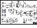
POWER TRANSFORMER REFERENCE TABLE
4007
1/4W
4
USE ADAPTER PATCH CABLE
YS#3088. (SEE LAYOUT PDF
FOR CE MODIFICATION IF NO
PATCH CABLE IS AVAILABLE)
CH1343U
SHOWN
100N
C24
250V
6
411Vdc
410Vdc
352Vdc
302Vdc
279Vdc
L1:A
D1
1
7
W3:D 6
4
W3:F 6
3 W2:A
10N
C1
500V
BLACK
2
W3:B 6
R28
1.0W
15K
.
.
4007
3 W2:B
7
82U
C13
450V
D3
10U
C14
450V
22U
C15
450V
22U
C16
450V
22U
C36
450V
D4
S1
2
R27
1.0W
15K
.
4007
6
POWER
22N
C18
275V
R26
1.0W
10K0
3500mH
4077
4007
D2
W3:E 6
4007
5
3
8
YELLOW
3 W2:C
8
CE
Fuse: T400mA
9
FOR CE: CUT X1 & X3
AND WIRE W3:C to W3:E.
X3
4N7
C19
250V
North America
Fuse: T1A
X1
30.3Vdc
1
2 W5:A
28Vac
XF_P2
16AWG
IEC_RECT
R63
1.0W
47R
GRN
W3:C 6
W4
35Vdc
D11
4007
4007
3
BLUE
100N
C37
63V
IGND
2
24.9Vdc
.
R57
1.0W
47R
R56
5.0W
33R
.
470U
C34
63V
D12
4007
470U
C41
63V
U1
7824
+24 RegOUT
REF
.
6731
220U
C35
35V
D10
2 W5:B
IN
V2:C
2X_TRIODE_HCT
{Voltage}
{Watts}
TO220
9
100N
C22
63V
V1:C
2X_TRIODE_HCT
{Voltage}
D9
XF_P1
W3:A 6
4007
1
WHITE
10
2 W6:A
1/4W
1
R30
100R
1/4W
XF_P2
R31
100R
10
{Voltage}
{Voltage}
PENTODE PENTODE
V4:B
V5:B
.
6.3Vac
V3:C
2X_TRIODE_HCT
{Voltage}
.
Product
XF_P1
11
2
IronHorse (DH40H)
power supply
2 W6:B
PCB# M1423
Date: Tue Feb 28, 2012 Rev: V03
Filename: M1423V03sch.sch2006
A
B
C
D
E
F
G
H
I
J
K
L
M
N
O
P
Sheet 2 of 3
YsType: YsType
Q
11
Function
3
4148
NA
CE
Q2
J3
W42 YEL
FROM_SW
C19
SPDT TOGGLE
S1
6549
POWER
4007
6451
250V
4N7
GRN
W4
S5
6559
STBY
CLINCH
W2
AC_Hi
DPDT TOGGLE
R51 R52
5865
100N
WHT
NC
C24
M1423
4148
1
2343
LEDs
470U
63V
R55
5621
D16
V01
100K
MPSA13
W35
6
RT
V
15K
AC_Mid
R62
R43
22K
C22
R34
LONG AXIS
ORIGIN
SEE LAYOUT DOCUMENTATION
+
RELAY 1C
RELAY 1C
1N5
C12
1N5
C11
NC
NO
R65
R76
TP2
56K
47R
1
W26
C10
470N
MPSA06
Q6
2K2
220K
680P
8
2348
Pots/Switching
15A
R56
P1
500K
4425
Gain
12
5840
VE
EE
SL
W33
R32
1K
C25
R37
22U
50V
C28
W21
470N
R68
Q3
BC550C
BC550C
Q5
S3
Q4
47P
1M
R4
1
RING
M1423 4/4 BLK
Gold
R19
2N2
2N2
15K
R41
330K
V1
3732
6
J6
R42
5840
22N
400V
C30
.
2329
YEL GRN
TIP-SW
2335
WHT
12
W26_
C43
C20
Gold
Footswitch
Gold
3450
22U
50V
C6
To_Pots/Switching
113K
ClinchRepeats - [email protected]@0.000
R74
R67
2K2
2K2
4148
56K
C44
56K
47R
WHT
W27_
MPSA06
C2
C1
R22
C48
100K
4148
1N
C47
500K
R79
4444
R71
R75
D19
R81
D18
2K
1/2W
P2
Bass
R14
1K54
10K
2K
1/2W
W27
C23
C37
100N
W31 BLK
OUT_GND
2/4
YEL
RED
LD2
LD1
6399 Push-Pull
R61 Standby 6398
StepAndRepeat - [email protected]@0.000
4
680P
C21
100K
4
To_Master
2337
10K
R13
C8
400V
22N
113K
C27
1U
BC550C
Q1
W32
3921
Master
2357
R23
2356
33R
5.0W
1
820R
R12
R18
V3
3732
WHT
2335
113K
2N2
C38
TIP
1
R70
500K
330K
1M
1M
100K
R10
R21
V2
3732
C40
1U
C42
R72 R39 R40
68K
Input Lo
D8
4148
R78
10K
2K2
R80
R66
K6
3696
R11
WHT
2335
0
584
J2
R59
J1
C46
1N
4444
1
R24
3N3
100K
P3
R8
Treble
C
2
4
2200V
N
58
40
V
4002N
2
450V
22U
Gold
680R
J7
WHT
6731
3696 K4
V4
3984
.
R7
4157
LOC
C15
5973
R46
Gold
Preamp Out
C35
4424
8799
M1423
V01
3/4
1R
2W
WHT
2335
R5
1K54
100K
100K
TP1
W6
BEC
1M R58
R26
Gold
Gold
3450
BLKYEL
Master
R2
M1423
V01
1/4
4158
P4
D11 IronHorse (DH40H)
U1
D12
C34
4007
100N
7824
+24 Reg
{Watts}
TO220
4007
D9
2W
1R
1
Gold
Poweramp In
10K0
1.0W
J5
Gold
3450
10N
C5
D10
R1
V5
3984
.
W1
3417
35V
220U
4007
R63
C41
4007
To_LEDs
RT
V
P5
10U
63V
47R
1.0W
6
D14
R45
470U
63V
10K
R57
2327
22K
R38
D15
4148
47R
1.0W
1
W35_
5621
BIAS
NO
C33
C2
C1
4157
3696
10U
63V
C45
RELAY 1C
D5
10U
R53
63V
TP3
4148
2K2
0R
75 0W
7.
0R
75 0W
7.
R48
2K2
1M
K2
D3
L1
W8
Output XF Primary
2335
4007
4158
4007
C1
10
N
C31
D4
160V
10U
C26
1
2.0W
1K
36K
36K
J4
4077
3500mH
WHT
2335
C32
220P
W5
D1
82K
R77
INSERT
4007
4007
C13
Gold
Gold
RT
V
R9
R54
D2
5902
82U
450V
Out
1K
2.0W
D17
Gold
Gold
3450
Gold
RT
V
SHORT AXIS
C18
275V
22N 6435
Out
3450
Gold
450V
10U
3
R47
R25
3
C14
5959
Filaments
C4 100N
1K5
6
1K54
1
R50
C3
R35
NO
W3
100R
100R
RT
V
R28
NC
R6
5973
C16 RT
V
C36
5973
3921
Input Hi
68K
C2
C1
R27
1.0W
15K
RT
V
1B
1
R60
15K
1.0W
R16
1B
4160
C39
R29
470K
1B
RT
V
63V
10U
1M
R20
47P
22U C17
450V
450V
22U
5840
RING-SW
R31
R30
1K54
22N
400V
TIP
680R
R36
56K
C29
TIP-SW
1M
RING-SW
VE
EE
SL
15K
15K
2K2
1
ORIGIN
100N
R33
56K
R15
1M
1K54
RING
Pcb Mech M1423V01
Top Assy M1423V01
Into Wave
W34
W20
R49
R44
PURE
1K5
GRN
LD3
Single-Ended
6396
BlankSize - 12500x11500
YS Type -{Company Name}
TIP-SW
BLK
VE
EE
SL
12
8
W26
1
WHT
3/4
C44
500K
R79
4444
P2
R68
470N
3N3
C10
Q3
BC550C
100K
BC550C
Q5
S3
R76
R65
10K
2K
1/2W
W27
2K2
Master
2357
1
4424
100K
4
R70
220K
680P
6451
250V
4N7
W4
Out
SWITCH SUPPORT PLATE LIMIT
D16
4148
3
4
6
S5
S1
W3
POWER
SPDT TOGGLE
X1
C18
STBY
DPDT TOGGLE
1K5
R62
Q2
W35
1
D17
6
2343
LEDs
6398
Push-Pull
RED
LD1
R77
LD3
GRN
Single-Ended
6396
X3
CLINCH
ORIGIN
4148
XFMR-Pri
1
1
6559
6399
Standby
YEL
LD2
1K5
6549
4160
R61
100K
MPSA13
6435
22N
275V
2/4
M1423 DH40H V03
GRN
INSERT
VCDORIGIN
M1423
SEE LAYOUT DOCUMENTATION
C23
BlankSize - 12500x11800
R34
W31 BLK
OUT_GND
C19
MPSA06
D8
4148
R78
10K
2K2
R80
R66
C46
1N
WHT
3696 K4
Q4
V03
StepAndRepeat - [email protected]@0.000
500K
4444
Treble
P3
D11
D12
4007
4007
NO
+
RELAY 1C
P4
D10
4007
10K
P5
W5
NC
100N
AC_Mid
C24
4148
1N
C47
K6
3696
R24
5865
-
2335
100N
C11
C2
C1
C37
WHT
R52
W2
AC_Hi
BIAS
C33
4157
10U
63V
D9
R43
22K
C12
1N5
Master
100N
47R
1.0W
RT
V
15K
2K2
1M
4007
36K
36K
R51C31
C22
C34
5621
NO
M1423 DH40H V03
1/4
R63
6
2327
22K
R38
D15
4148
47R
1.0W
1
W35_
10U
63V
C45
RELAY 1C
D5
10U
R53
63V
K2
C2
C1
R54
4007
U1
470U
63V
NC
1N5
3450
D2
W42 YEL
FROM_SW
4007
4158
6731
4007
To_LEDs
D14
R45
TP3
4148
2K2
D3
4007
D1
3
C1
10
N
8799
7824
+24 Reg
{Watts}
TO220
R55
C1
WHT
2335
R1
D4
5902
82U
450V
4007
J4
3450
R57
3696
RT
V
Out
5621
1
J3
0R
75 0W
7.
0R
75 0W
7.
160V
10U
C26
1
RT
V
3
L1
R47
1
4077
3500mH
R48
RT
V
1B
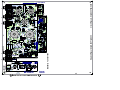
Pcb Mech M1423V03
Top Assy M1423V03
3
WHT
2335
2W
1R
1
450V
10U
1R
2W
470U
63V
1B
5959
MPSA06
Q6
R2
C41
2.0W
1K
NO
W8
Output XF Primary
R25
1K
2.0W
PURE
NC
R50
C14
RT
V
RELAY 1C
C2
C1
4158
D18
2K
1/2W
330K
R23
2356
C21
470N
C48
V4
3984
680P
1K54
R5
100K
TP1
R7
100K
1B
V5
3984
Top M1423 V03
56K
47R
R74
R67
TP2
Bass
58
40
56K
47R
R22
100K
M1423
2348
Pots/Switching
500K
15A
4425
P1
Gain
R56
33R
5.0W
2K2
2K2
4148
56K
R71
R75
D19
R81
R8
Filaments
M1423 4/4
WHT
47P
1M
4
2337
1
820R
R11
10N
C5
2335
WHT
To_Master
10K
R12
1M
R13
W6
1
M1423
DH40H
V03
W27_
1M
C
2
4
2200V
N
82K
C32
220P
W33
R32
1K
C25
R37
C28
22U
50V
R14
R18
WHT
R9
YEL GRN
RING
2329
22N
400V
C30
5840
C8
113K
400V
22N
5840
LOC
BEC
C1
5
R26
10K0
1.0W
3732
C35
35V
220U
C4 100N
4157
1K54
100R
100R
BLKYEL
V3
450V
22U
C3
J7
W21
1K54
R35
R28
100K
R10
R58
1M
J5
3450
R31
R30
RT
V
5973
RT
V
450V
22U
15K
1.0W
RT
V
1.0W
15K
R27
5973
2335
5973
C16
R6
R29
1M
47P
22U C17
450V
R49
R44
W32
3921
Input Lo
V
4002N
2
R46
C39
R60
2335
12
W26_
6
1
113K
R21
R20
0
584
Preamp Out
J2
680R
1K54
Poweramp In
W1
3417
100K
R4 6588 1/2W
C27
C40
C42
3450
R36
56K
W20
68K
C36
63V
10U
680R
C6
To_Pots/Switching
22U
50V
2N2
R19
C20
C43
2N2
J6
R42
R41
15K
330K
3450
1U
2N2
1U
Q1
C38
R59
1M
TIP
68K
RING
15K
15K
2K2
3921
Input Hi
TIP-SW
R72 R39 R40
BC550C
R16
3732
RING-SW
V2
470K
V1
TIP
3732
22N
400V
J1 RING-SW
VE
R33
56K
R15
1M
1K54
5840
EE
SL
100N
W34
C29
ClinchRepeats - [email protected]@0.000
Into Wave
Footswitch
SEE LAYOUT DIAGRAM
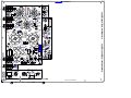
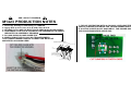
M1423 PRODUCTION NOTES
1. Screw U1 directly to PCB using 1x YS#8799.
2. Apply RTV to C13 C14 C15 C16 C26 C34 C36 C41.
3. KEYWAY OF S1 AND S5 MUST FACE ARROW ON SILKSCREEN.
4. HARDWARE FOR 6549 & 6559 MUST BE ASSEMBLED IN ORDER
INDICATED IN ASSEMBLY DRAWING.
5. R4 100K #6588 IS HAND INSERTED.
6. WHEN USING THE CH1343 (NA TRANSFORMER),
THE TRANSFORMER'S MOLEX CONNECTOR MUST BE
MODIFIED AS SHOWN HERE:
ASSEMBLY OF 6549 SPDT AND 6559 DPDT
WITH Z1295 AND NUTS AND WASHERS
6559 DPDT SWITCH
Z1295 SWITCH WASHER
6pin
CONNECTOR
PLACE IMAGE HERE
THIS TRIMMED CORNER OF
Z1295 SHOULD BE ORIENTED
CLOSE TO LABELED TABS
NUT WITH DOUBLE SIDE CHAMFER
INSIDE TEETH WASHER
CHASSIS
FRONT PLATE
KEYED WASHER
NUT WITH ONE SIDE CHAMFER
7. FOR CE OPERATION WITH A CH1343U, USE ADAPTER PATCH
CABLE (YS#3088) BETWEEN THE TRANSFORMER AND PCB.
IF A PATCH CABLE IS NOT AVAILABLE, THE POWER SWITCH
PCB CAN BE MODIFIED AS BELOW:
PLACE IMAGE HERE
SEE PRODUCTION NOTES
M1423_PCB_DATABASE_HISTORY
M1423.PCB_DATABASE_HISTORY
MODEL(S):-
MODEL
VER# DESCRIPTION OF CHANGE
# DATE
N
1 11-JAN-2011 V01
PC8221: #4160 new AC pattern. #4646 update. GG
2 12-APR-2011 V02
V
PC8264: Change R4 #4776 with #6588 hand insert GG
3 D
PC8351: RETAPED AC PLUG AREA FOR CH1343/E/U. - ML
4 27-FEB-2012 V03
N
V
5 D
V
N
6 D
N
V
7 D
N
V
8 D
V
N
9 D
N
V
10 D
N
V
11 D
V
N
12 D
N
V
13 D
1 D
V
N
2 D
V
N
3 D
V
N
4 D
V
N
5 D
V
N
6 D
V
N
7 D
V
N
8 D
V
N
9 D
V
N
10 D
V
N
11 D
V
N
12 D
V
N
13 D
V
N
1 D
V
N
2 D
V
N
3 D
V
N
4 D
V
N
5 D
V
N
6 D
V
N
7 D
V
N
8 D
V
N
9 D
V
N
10 D
V
N
11 D
V
N
12 D
V
N
13 D
V
N
MODEL(S):#
1
2
3
4
5
6
DATE
D
D
D
D
D
D
MODEL(S):#
1
2
3
4
5
6
PC#
PC
PC
PC
PC
PC
PC
REF
P1
P2
P3
P4
P5
R
R
R
R
R
R
R
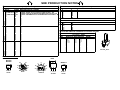
FUNCTION PART# KNOB
GAIN
BASS
TREBLE
MASTER
Bias Trim
F
F
F
F
F
F
F
78XX
G2
G1
4
P 3
6
H 2
7
1
C B E
TO-92
NC
EL34
8
H
H
5
K
G3
NC
H
4
5
6
2K 3
7
2G 2
8
1
MPSA13
1P
1G
1K
9
2P
HT
12AX7A
I G O
TO-220
MODEL
PENDING CHANGE
X
X
X
X
X
X
*PLACE IMPLEMENTED CHANGES INTO BOARD HISTORY
M1423 Potlist
Iron Horse - IH40H
MODEL(S):-
LEAD/PIN REFERENCE
BC550C
BC560C
MODEL
VER# DESCRIPTION OF CHANGE
V
N
V
N
V
N
V
N
V
N
V
N
M1423 PENDING CHANGES
EBC
TO-92
4425
4444
4444
4424
4520
P
P
P
P
P
P
P
8430
8430
8430
8430
n/a
K
K
K
K
K
K
K
{NEW}
N
N
N
N
N
N
N
N
N
N
N
N
"STYLE_P32"
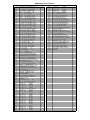
DH40H Parts List 11/15/2011
YS No.
6384
6396
6398
6399
6438
6825
6731
5101
5103
5105
5277
5408
5206
5208
5273
5275
5816
5204
5840
6435
6451
9961
5212
5234
5865
5256
5629
5631
5945
5959
5973
5268
5621
5902
4424
4444
4425
4520
711
3976
4077
8522
3478
3489
3601
3449
3450
3921
2403
8696
8889
3438
3810
4160
4157
4158
8430
8923
3428
8800
8844
4597
4646
4704
4613
4817
4852
4873
4680
4822
4747
4823
4824
4791
4631
4847
4829
5031
4830
6159
4832
4868
4835
4836
4837
4838
6588
Description
JEWELED PILOT LAMP AMBER ROHS V1
GREEN 5MM LED 2V1 20MA HIGH EFF
RED 5MM LED 1V5 20MA HIGH EFF
YEL 5MM LED 1V5 20MA HIGH EFF
1N4007 1000V 1A0 DIODE
T&R
1N4148 75V 0A45 DIODE
T&R
L7824
TO220 P 24V0 REG
BC550C
TO92 NPN TRAN T&R TB
MPSA06
TO92 NPN TRAN T&R TA
MPSA13
TO92 NPN DARL T&R TA
220P 200V 5%CAP T&R RAD CER.2NPO
_47P 100V 10%CAP T&R BEAD
NPO
__1N 400V 5%CAP T&R RAD .2FLM
__2N2 400V 5%CAP T&R RAD .2FLM
__1N5 200V 5%CAP T&R RAD CER.2NPO
__3N3 100V 5%CAP T&R RAD .2FLM
680P 100V 5%CAP T&R RAD CER.2NPO
_10N 100V 10%CAP T&R RAD .2FLM
_22N 400V 10%CAP BLK RAD POLY FLM
_22N 275V 20%CAP BLK 'X2' 15MM AC
__4N7 250V 20%CAP BLK 'Y' 10MM AC
_10N 500V 20%CAP RAD CER DISC BULK
100N 63V 5%CAP T&R RAD .2FLM
470N 63V 10%CAP T&R RAD .2FLM
100N 250V 10%CAP BLK RAD POLY FLM
__1U 63V 5%CAP T&R RAD .2FLM
_10U 160V 20%CAP BLK 10X13MM EL
_22U 50V 20%CAP T&R 6X7MM .2EL
_10U 63V 20%CAP T&R RAD .2EL
_10U 450V 20%CAP BLK
EL
_22U 450V 20%CAP BLK
EL
220U 35V 20%CAP T&R RAD .2EL
470U 63V 20%CAP BLK 12X25MM EL
_82U 450V 20%CAP BLK 22X30MM
100K 1B LIN 9MM
P32
500K 1B LIN 9MM
P32
500K 15AAUDIO 9MM
P32
_10K
TRIM POT
30 X 50 X 1.5MIL PLASTIC BAG
SNAP ON 0.843" INSULATING BUSHING
3.5H CHOKE 50MA 0R137 IRON CORE
RUBBER BUMPER WITH WASHER -SMALLCLIP 205/187X032 18-22AWG DISCO/INS
CLIP 250X032 18-22AWG DISCO/INSL
RING TERMINAL 16AWG WIRE & #8 SCREW
NEUTRIK JACK NUT RED
1/4" JCK PCB MT ALL-GOLD SKT
1/4" JCK PCB MT VERT STER RT SWT
T2,0AL
5X20MM FUSE
AP-SERIES HANDLE- BARE 6061-T6 ALUM
RUBBER GROMMET #2183-034-BLK
IEC PWR SOC W/.205TAB &FUSE 10A250V
4" NYLON CABLE TIE
3X2PIN 4.2MM RA HEADER VAL-U-LOK
2PIN 4.2MM HEADER VAL-U-LOK
3PIN 4.2MM HEADER VAL-U-LOK
KNOB CHICKEN-BEAK
6-32 THUMB SCREW - ALUMINUM
8' 3/18 SJT AC LINE CORD REMOVABLE
6-32 KEPS NUT ZINC
6-32 PEMNUT
22AWG STRAN TC WIR
JMP
2.0W 1R 5% WIREWND T&R RES
5.0W 33R 5%
BLK RES
1.0W 47R 5%
T&R RES
1/4W 47R 5%
T&R RES
1/4W 100R 5%
T&R RES
1/4W 680R 5%
T&R RES
7.0W 750R 5% STANDOFF BLK RES
1/4W 820R 5%
T&R RES
2.0W 1K 10%
BLK RES
1/4W 1K 5%
T&R RES
1/4W 1K5 5%
T&R RES
1/4W 1K54 1%
T&T RES
1/2W 2K 5%
T&R RES
1/4W 2K2 5%
T&R RES
1/4W 10K 5%
T&R RES
1.0W 10K0 5%
T&R RES
1/4W 15K 5%
T&R RES
1.0W 15K 5%
T&R RES
1/4W 22K 5%
T&R RES
1/4W 36K 5%
T&R RES
1/4W 56K 5%
T&R RES
1/4W 68K 5%
T&R RES
1/4W 82K 5%
T&R RES
1/4W 100K 5%
T&R RES
1/2W 100K 5%
BLK RES
Qty.
1
1
1
1
9
7
1
3
2
1
1
2
2
3
2
1
2
1
5
1
1
1
4
2
1
2
1
2
4
1
3
1
2
1
1
2
1
1
1
1
1
4
2
1
3
2
5
2
2
1
3
1
7
1
2
2
4
4
1
3
4
3
2
1
2
2
2
2
2
1
2
1
2
5
2
7
3
1
4
2
2
2
5
2
1
6
1
YS No.
4776
4841
4842
4843
4844
3696
8799
8808
8832
8807
8801
8829
8824
8999
8791
8708
2335
3417
3865
8482
8488
8652
3511
8850
2356
6559
3429
6549
3392
3384
12AX7
EL34
3732
3984
1407
CH1343
CH1343M
Description
1/4W 113K 1%
T&R RES
1/4W 220K 5%
T&R RES
1/4W 330K 5%
T&R RES
1/4W 470K 5%
T&R RES
1/4W 1M 5%
T&R RES
RELAY 1C 02AMP DC24 006MA PC-S
#6 X 1/4 PAN PH TYPE B JS500
4-40 X 3/4 FLAT PHIL MS B.O.& WAX
6-32 X 1/4 PAN PH TAPTITE JS500
6-32 X 5/16 PAN PH MS JS500
6-32 X 3/8 PAN PH TAPTITE JS500
6-32 X 3/8 FLAT PH TAPTITE BO#C HEA
8-32 X 5/16 PAN QUAD TAPTITE JS500
8-32 X 5/8 PAN PH TAPTITE JS500
8-32 X 2 PAN PH TAPTITE ZINC CLEAR
10-32 X 3/8 FILLISTER QD MS ZN
NYLON STANDOFF NUT #4 500MIL
6-32 SCREW TERMINAL PC MNT SNAP-IN
1/2 PLASTIC HEX SPACER #6
3/8 1D FLAT WASHER
3/8 INT TOOTH LOCKWASHE ZINC
SHOULDER WASHER .483" X .125" BLACK
#6 FLAT WASHER NYLON
#10 INT TOOTH LOCKWASHER BO
DPDT MINI SW PCMT V TOG ON-ON-ON
DPDT TOGGLE SW MINI ON-OFF-ON
SPDT ROKR SW QUIK 180' AC PWR BL/BL
SPDT TOGGLE SW MINI LRG BAT
250 MALE TAB .2IN
T&R
12AU7 JJ DUAL TRIODE PREAMP TUBE
12AX7 DUAL TRIODE PREAMP TUBE
EL34 PENTODE OUTPUT TUBE
9 PIN PC MOUNT TUBE SOCKET BE
8 PIN PC MOUNT TUBE SOCKET BE
DH40H POWER TX SHIELD !FIRST 200!
DH40H XFMR
DH40H OPT
Qty.
2
1
2
1
8
3
1
6
3
2
15
8
4
4
4
2
6
1
2
4
2
1
2
2
1
1
1
1
2
1
2
2
3
2
1
1
1