1
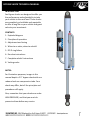
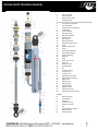
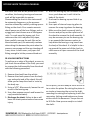
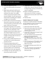
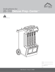
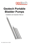
BYPASS SHOCK TECHNICAL MANUAL INTRODUCTION Fox Bypass shocks are designed to offer you the performance and adjustability to take your vehicle to the next level. These shocks are completely re-‐buildable and repairable to offer a long life on your vehicle and great value to your investment. CONTENTS 1. Exploded diagram 2. Principles of operation 3. Adjustment and tuning 4. When to re-‐valve, when to rebuild 5. IFP O-‐ring failure 6. Re-‐valve instructions 7. Complete rebuild instructions 8. Valving codes NOTES: For illustration purposes, images in this manual depict a 2.5” bypass shock with one rebound and one compression tube. Your shock may differ, but all the principles and procedures still apply. Also, remember that your shocks are under HIGH PRESSURE, and that you must de-‐ pressurize them before any service. 1 BYPASS SHOCK TECHNICAL MANUAL 1. Piston Lock Nut 2. Back-‐Up Washer 3. Rebound Valve Stack 4. Damping Piston *Your piston will have an O-‐ring under the wear band, M 5. Compression Valve Stack 6. Top-‐Out Washer 7. Damping Piston Wear Band 8. Shaft Spacer 10. Internal Bearing 11. Bearing Housing 12. Bearing U-‐Cup Seal 13. Retaining Ring 15. Bearing Cap 16. Bearing Set Screw 17. Bearing Cap Wiper Seal 18. Shaft 19. Bottom-‐Out Bumper 22. Eyelet 23. Eyelet Spacer/Reducer 24. Eyelet Retaining Ring 25. Spherical Bearing 26. Body Cap 31. Body 36. Reservoir End Cap 37. Reservoir 38. Reservoir Decal 39. IFP Wear Band 40. IFP 41. Air Valve Housing 42. Air Valve Core 43. Air Valve Cap 52. Bypass Reservoir Tube 53. Bypass Reservoir Fitting 54. Bypass Tube 55. Bypass Piston 56. Bypass Spring 57. Bypass Plunger 58. Bypass End Cap 59. Adjustment Screw 60. Adjustment Screw Lock Nut O-‐RINGS A. Bearing Housing B. Shaft Bearing D. Body Cap E. Air Valve Housing F. Reservoir End Cap G. IFP K. Bypass Reservoir Fitting L. Bypass Plunger M. Damping Piston 2 BYPASS SHOCK TECHNICAL MANUAL PRINCIPLE OF OPERATION At the core of the bypass shock is a normal reservoir shock. It has a damping piston with valve stacks on both sides. However, where the bypass shock differs is the externally mounted bypass tubes. These tubes allow shock oil to travel around the piston for certain portions of the travel. This makes the shock position-‐sensitive. Generally the shocks are tuned to ramp up damping force as the shock travel increases, while allowing less damping closer to ride height. This combination provides excellent vehicle performance over a wide range of obstacle sizes at a wide range of speeds. Additionally the shock will reduce bottoming out of the suspension thus reducing the forces seen by the bump-‐stops and chassis of the vehicle. The end result is increased speed and performance over rougher terrain. A typical bypass circuit is shown. The “head” of the bypass unit houses an adjustable check valve. The check valve ensures that the particular bypass circuit is only active in one direction: compression for blue units and rebound for red units. The adjustment is used to set how far the valve will open. This adjustment is external to the shock and can be set at any time without tear-‐down or de-‐ pressurizing of the shock. A particular bypass circuit is only active when the damping piston is between the inlet and outlet of the bypass unit and travelling in the prescribed direction, and has no effect otherwise. Typically more bypass units are active close to ride height, reducing damping for that area. As the shock is compressed or extended from ride height, less units are active until you reach the end zones where none are active. The end zone regions are known as the top-‐out and bottom-‐out zones, and only the piston valving is active in these sections of the travel. 3 BYPASS SHOCK TECHNICAL MANUAL ADJUSTMENT AND TUNING Tuning external bypass shocks is a very individual process. Driver preferences as well as type of vehicle and terrain play a huge role. The key to successful tuning is to understand when each bypass circuit is active. Adjustment procedure: 1. Loosen the lock nut on top of the bypass unit while holding the adjuster with an Allen key. Back it off far enough that you can close the adjuster without the nut bottoming out. 2. Close the valve completely with an Allen key while counting rotations. You will feel increased resistance when the valve is closed. 3. Open the adjuster to the new setting by counting turns. 4. Tighten the lock nut while holding the Allen key still. *Do not allow the bypass end cap to come loose (the red or blue aluminum part). It may be necessary to hold it with a wrench while breaking the lock nut loose. Fox recommends that as a starting point short tubes are set 6 turns from fully closed and long tubes are set 3 turns from fully closed. This applies to both rebound and compression tubes. Increasing the number of turns will decrease the amount of damping while the circuit is active and vice-‐versa. Adjustments are generally made in increments of one turn at a time. A zip-‐tie on the shock shaft to serve as a travel indicator will give you a clear idea of the amount of travel used and will help determine what adjustments need to be made. The goal is to use all the travel of the shock on the roughest terrain you will encounter. When the bypass circuits are being tuned, the suitability of the main piston valving can come into play. This can happen in rebound, compression, or both. When the adjusters are set closed or almost closed, this is an indication that the main valving is too soft. Conversely if the adjusters are set nearly fully open, this is an indication that the main valving is too stiff. When this conclusion is reached, it is time to re-‐valve the shock. WHEN TO REBUILD Re-‐valving the shock can be done without a full rebuild of the shock, or it can be done in combination with an overhaul. If this is beyond your capabilities, the Fox Factory can perform this service for you. For non-‐race vehicles, Fox recommends an overhaul each season. For race vehicles, Fox recommends a rebuild after each race, however as a minimum the oil condition needs to be checked. The oil should be red and not smell burnt. IFP O-‐RING FAILURE The reservoir has an internal floating piston (IFP) that separates the shock oil from the nitrogen. If the O-‐ring seal on the IFP fails, 4 BYPASS SHOCK TECHNICAL MANUAL the shock fluid side will be pressurized. In this condition, the bearing housing and reservoir ends will be impossible to remove. Disassembling the shock in this state would be extremely dangerous, so the pressure must be released by carefully cracking open a fitting on the shock. On a remote reservoir shock loosen one of the hose fittings, and on a piggy back shock loosen one of the bypass units. To crack open the bypass unit, first make sure the unit is adjusted fully open, then carefully unscrew the unit (the red or blue aluminum part). Be extremely cautious when doing this because the point when the pressure can escape and the cap shooting off is very close. In both cases, only open the fitting enough to let the pressure bleed out. RE-‐VALVING INSTRUCTIONS To perform a re-‐valve of the shock, or even to just check the condition of the fluid, you need to remove the shaft assembly from the shock with the following procedure: 1. Remove the shock from the vehicle. 2. Remove the shock spacers from the body cap, and eyelet end of the shock, this will allow you to clamp the shock in a vise by the body cap. 3. Using a 5/32” Allen wrench, loosen the set screw in the bearing cap. 4. Use a face-‐spanner wrench and loosen the cap (counterclockwise). 5. Discharge the shock, failure to do so will leave the shock pressurized and can cause injury. 6. With the bearing cap still threaded on by 2 turns, push down on it until it hits the body of the shock. 7. Unscrew the bearing cap and slide it up the shaft. 8. Use a pair of internal snap ring pliers to remove the snap ring above the bearing. 9. Make sure the shock is securely held in the vice and pull up on the eyelet end of the shock to remove the shaft assembly. It may be necessary to use the bearing cap in an upward slide-‐hammer motion to help brake the bearing o-‐ring loose from the body of the shock. It is helpful to tie a rag around the open end of the shock to catch excess oil upon removal of the shaft assembly. At this point, you are ready to check the oil or to re-‐valve the piston. Re-‐valving the piston is as simple as loosening the nut on the shaft, removing the valving and replacing it with the new setup. Valving combinations are shown at the end of this document. Torque the nut to 30 ft-‐lbs. Now you are ready to re-‐install the shaft: 5 BYPASS SHOCK TECHNICAL MANUAL 1. Inflate the reservoir to 10 PSI. 2. Insert the shaft assembly into the shock body. 3. Begin slowly pushing the shaft up and down in the oil to remove air trapped in and behind the valves. Use a rubber mallet to tap the shock shaft to release any stuck bubbles. You will know you are finished with the bleeding when bubbles no longer rise to the surface. 4. Pull the shaft up until the first Al spacer is flush with the top of the shock body. The oil level should be up to the bottom of this spacer. (Add more if necessary) 5. Slide the bearing down until it contacts the Al spacer, then slowly push the entire assembly into the shock body. As the bearing is pushed into the body excess oil will escape through the groove on the bearing. If no oil comes out, there was not enough oil to begin with and now an air pocket is trapped inside. 6. Once you feel confident that all the air is out of the shock, remove the pressure from the reservoir. 7. Slide the bearing cap down until it contacts the bearing. Push the cap down further until it hits the body, this will push the bearing down into the shock body, allowing access to the snap ring groove. 8. Install the snap ring into the groove, and clean off any excess oil residue. 9. Charge shock with 200 PSI of nitrogen. Failing to do so now will allow the bearing to rotate during next step, and the bearing cap will not get tight. 10.Tighten the bearing cap with a face-‐ spanner wrench, and lock it in place by tightening the set screw with a 5/32” Allen wrench. 11.Check for leaks. COMPLETE REBUILD OF THE SHOCK To perform a complete overhaul of the shock, you will change the various O-‐rings and seals throughout, and change out the oil. 1. Remove the shock from the vehicle. 2. Remove the shock spacers from the body cap and eyelet end of the shock, then clamp the shock in a vise. 3. Using a 5/32” Allen wrench, loosen the set screw in the bearing cap. 4. Use a face-‐spanner wrench to loosen the bearing cap (counterclockwise). 5. Discharge the shock, failure to do so will leave the shock pressurized and can cause injury. 6. With the bearing cap still threaded on by 2 turns, push down on it until it hits the body of the shock. 7. Unscrew the bearing cap and slide it up the shaft. 8. Use a pair of internal snap ring pliers to remove the retaining ring above the bearing housing. 6 BYPASS SHOCK TECHNICAL MANUAL 9. Make sure the shock is securely held in the vice and pull up on the eyelet end of the shock to remove the shaft assembly. 10.With the shock still in the vice, remove the reservoir end cap with the Schrader valve. It may be necessary to tap the cap into the reservoir using a rubber mallet (with the valve cap installed). Using a pair of internal snap ring pliers remove the snap ring. Keep in mind that all of the surfaces inside the reservoir are sealing surfaces, and cannot be scratched. 11.Now that the reservoir end cap has been removed, you will be able to see the backside of the Internal Floating Piston (IFP). This IFP separates the Nitrogen from the oil, and must be set at the proper height during assembly. Use the wooden end of a hammer to push the IFP towards the hose-‐fitting end. This will push the remaining oil from the reservoir into the shock, allowing all the oil to be dumped. 12.Remove the hose-‐fitting end of the reservoir in the same manner as before. Now that both ends of the reservoir have been removed, the IFP may be removed and cleaned. If changing the IFP O-‐ring, be careful not to scratch the O-‐ring gland, doing so may result in an O-‐ring failure. 13.To disassemble the bypass unit, loosen the red or blue cap with a wrench. Remove the cap with the plunger and adjuster screw as a unit. Beneath the plunger is a small spring and the check valve, these can be removed with a magnet, or by simply turning the shock upside down. 14.Replace the two O-‐rings on the plunger assembly. Be careful not to scratch the O-‐ ring gland with the pick. 15.Place the earlier removed shaft assembly into a vice, clamping on the eyelet. Remove the piston nut. 16.Carefully remove the damping piston from the shaft assembly, and place on a clean rag or towel. The valve shims may be laid in a row to easily inspect and measure if needed. Be sure to note the order that the valves were removed. 17.Remove the bearing housing and bearing cap from the shaft. 18.To remove the wiper from the bearing cap, use a pick or scribe, and pry inward. 19.Both the O-‐ring and U-‐cup inside the bearing can be removed with a pick or scribe. Once again, stick the pick into the seal, and pry inward towards the center of the bearing, being careful not to scratch the seal glands. 20.Make sure everything is clean before installing new seals ASSEMBLY Generously apply oil or grease to all o-‐rings and seals before installation 1. At this time re-‐valve the shock, if necessary. (see chart) 2. Re-‐install the bearing and bearing cap onto the shaft, grease the seals in the bearing, and rock the bearing while installing onto the shaft. 7 BYPASS SHOCK TECHNICAL MANUAL 3. Once the new valving has been stacked on the piston, and the compression side of the piston has been installed towards the shaft, torque the nut to 30 ft-‐lbs. The lock nut should be replaced if you can spin the nut on by hand. 4. Set shaft assembly aside until step 18. 5. Re-‐install the bypass units into the bypass tubes. First install the bullet shaped check valve, next the spring, and finally the cap/ plunger unit. Use a dab of grease on the plunger. For piggyback shocks, skip to step 13. 6. Re-‐install the reservoir hose. Be sure the hose fittings on both ends are tight. 7. Place the IFP back into the reservoir, making sure that the O-‐ring and wear band are installed. Set the surface of the IFP w/o the threads five inches from the top. 8. Add oil to reservoir on top of the IFP. The oil side is the side w/o the threads. 9. Insert the reservoir end cap into the reservoir making sure that the end cap O-‐ ring is re-‐installed. The O-‐ring should be wiped with shock oil to ease installation. 10.Using internal snap ring pliers, re-‐install the snap ring, to retain the previously installed reservoir end cap. 11.With the shock still in the vice, let the reservoir drop below the body cap to allow any air to rise to the surface. Next, with the reservoir still below the body cap, push the IFP until it tops out on the reservoir end cap, this will completely fill the hose with oil, and remove air from the reservoir and hose. For non-‐piggyback shocks, skip to step 16. 12.For piggyback shocks, place the IFP back into the reservoir, making sure that the O-‐ ring and wear band are installed. 13.With the shock still in the vice, slide the reservoir over the end cap that is attached to the welded fitting on the shock, making sure that the end cap O-‐ring is re-‐ installed. Using internal snap ring pliers, re-‐install the snap ring into the reservoir, (to retain the previously installed reservoir end cap), and then pull the reservoir down to seat the O-‐ring. 14. Secure the other end of the reservoir with the provided hose clamp. Do not over-‐ tighten the hose clamp 15.Put 10 PSI in the reservoir chamber to make sure the IFP doesn’t move. 16.Fill the shock with oil until it appears that oil has filled the reservoir and reservoir tube. At this point, air trapped in the compression tubes can be bled out by simply placing your hand over the base of the shock and flipping the shock over. You will be able to hear the bubbles rising to the surface. 17.Put the shock back in the vise 18.Now that all of the air has been bled from the system, insert the shaft assembly into oil to bleed the air from the valves. At this point, all the bypass tubes should be in the full open position. 8 BYPASS SHOCK TECHNICAL MANUAL 19.Begin slowly pushing the shaft up and down in the oil to remove air trapped in and behind the valves. Use a rubber mallet to tap the shock shaft down to release any trapped air. You will know you are finished bleeding when bubbles stop rising to the surface. Once you feel confident that all the air is out of the shock, release the pressure in the reservoir. 20.Pull the shaft up until the first Al spacer is flush with the open end of the shock body. The oil level should be to the bottom of this spacer. (Add more oil if necessary) 21.Slide the bearing down until it contacts the Al spacer then slowly depress the whole assembly into the body. As the bearing is pushed into the body, excess oil will escape through the groove on the bearing. If no oil comes out, there was not enough oil to begin with and an air pocket is trapped inside. Re-‐bleed if necessary. 22.Once you feel confident all the air is out of the shock, remove the pressure from the reservoir. 23.Slide the bearing cap down until it contacts the bearing. Push the cap down further until it hits the body, this will puss the bearing down into the shock body allowing access to the snap ring groove. 24.Install the snap ring in the groove and clean off excess oil residue. 25. Charge shock with 200psi of Nitrogen. Failing to do so now will allow the bearing to rotate during the next step and the cap will not get tight. 26.Tighten the bearing cap with a face spanner wrench and lock it into place by tightening the set screw with a 5/32” Allen wrench. 27. Check for leaks. 9 BYPASS SHOCK TECHNICAL MANUAL VALVING CODES AND VALVESTACK LAYOUT 10