1
ROOM AIR CONDITIONER
SERVICE MANUAL
CAUTION
BEFORE SERVICING THE UNIT,
READ THE SAFETY PRECAUTIONS IN THIS MANUAL.
��
�
��
�
��
��
MODEL: GWHD6500R ,GWHD6500RY6
CONTENTS
1. PREFACE
....................................................................................................................................................................... 3
1.1 FEATURES ........................................................................................................................................................................ 3
1.2 SPECIFICATIONS ............................................................................................................................................................. 3
1.3 SAFETY PRECAUTIONS ................................................................................................................................................. 3
1.4 INSULATION RESISTANCE TEST .................................................................................................................................... 3
1.5 LOCATIONS OF CONTROLS ........................................................................................................................................... 4
2. DISASSEMBLY INSTRUCTIONS
.................................................................................................................... 6
2.1 MECHANICAL PARTS ...................................................................................................................................................... 6
2.1.1 FRONT GRILLE ....................................................................................................................................................... 6
2.1.2 CABINET................................................................................................................................................................... 6
2.1.3 CONTROL BOARD ................................................................................................................................................... 6
2.2 AIR HANDLING PARTS .................................................................................................................................................... 7
2.2.1 AIR GUIDE UPPER................................................................................................................................................... 7
2.2.2 ORIFICE, TURBO FAN AND FAN............................................................................................................................. 7
2.2.3 MOTOR .................................................................................................................................................................... 8
2.2.4 AIR GUIDE ................................................................................................................................................................ 8
2.3 ELECTRICAL PARTS ....................................................................................................................................................... 8
2.3.1 OVERLOAD PROTECTOR ...................................................................................................................................... 8
2.3.2 COMPRESSOR ........................................................................................................................................................ 9
2.3.3 CAPACITOR ............................................................................................................................................................. 9
2.3.4 THERMISTOR........................................................................................................................................................... 9
2.3.5 CONTROL PANEL..................................................................................................................................................... 9
2.3.6 POWER CORD ...................................................................................................................................................... 10
2.4 REFRIGERANT CYCLE ............................................................................................................................................ 10
2.4.1 CONDENSER ........................................................................................................................................................ 10
2.4.2 EVAPORATOR ....................................................................................................................................................... 10
2.4.3 CAPILLARY TUBE ................................................................................................................................................. 11
3. INSTALLATION ......................................................................................................................................................... 13
3.1 SELECT THE BEST LOCATION ..................................................................................................................................... 13
3.2 HOW TO INSTALL .......................................................................................................................................................... 13
3.3 ELECTRICAL DATA ..................................................................................................................................................... 16
4. TROUBLESHOOTING GUIDE
........................................................................................................................ 16
4.1 OUTSIDE DIMENSIONS ................................................................................................................................................. 16
4.2 PIPING SYSTEM ............................................................................................................................................................ 17
4.3 TROUBLESHOOTING GUIDE ........................................................................................................................................ 18
5. SCHEMATIC DIAGRAM
...................................................................................................................................... 26
5.1 CIRCUIT DIAGRAM......................................................................................................................................................... 26
5.2 ELECTRONIC CONTROL DEVICE ................................................................................................................................. 27
5.3 COMPONENTS LOCATION(FOR MAIN P.W.B ASM)............................................................................................................... 28
5.4 COMPONENTS LOCATION(FOR DISPLAY P.W.B ASM) ......................................................................................................... 28
6. EXPLODED VIEW ................................................................................................................................................... 29
7. SERVICE PARTS LIST ......................................................................................................................................... 30
-2-
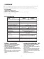
1. PREFACE
This service manual provides various service information, including the mechanical and electrical parts, etc.
This room air conditioner was manufactured and assembled under a strict quality control system.
The refrigerant is charged at the factory. Be sure to read the safety precautions prior to servicing the unit.
1.1 FEATURES
z
z
z
z
z
DESIGNED FOR COOLING ONLY
POWERFUL AND INCREDIBLE COOLING
TOP-DOWN CHASSIS FOR THE SIMPLE INSTALLATION AND SERVICE
WASHABLE ONE-TOUCH FILTER
COMPACT SIZE
1.2 SPECIFICATIONS
MODELS
GWHD6500RY6
GWHD6500R
ITEMS
6,500
COOLING CAPACITY (BTU/h)
1�, 115V, 60HZ
POWER SUPPLY (Phase, V, Hz)
INPUT (W)
670
OPERATING CURRENT (AMP.)
6.1
REFRIGERANT CONTROL
CAPILLARY TUBE
REFRIGERANT CHARGE (R-22)
TURBO
INSIDE FAN
PROPELLER FAN WITH SLINGER RING
OUTSIDE FAN
AIR DISCHARGE
2-WAY (RIGHT AND LEFT)
CHASSIS
PROTECTOR
350g (12.4 Oz)
380g (13.4 Oz)
TOP-DOWN
z OVERLOAD PROTECTOR FOR COMPRESSOR
z INTERNAL PROTECTOR FOR FAN MOTOR
TEMPERATURE CONTROL
THERMISTOR
2 SPEED (LOW FAN, HIGH FAN)
SWITCH
FAN MOTOR
6 POLES, 28W
are subject to minor change without notice for further improvement.
NOTE: Specifications
z
1.3 SAFETY PRECAUTIONS
1.4 INSULATION RESISTANCE TEST
1. When servicing, set the POWER of CONTROL
BOARD to Off and unplug the power cord.
2. Observe the original lead dress.
If a short circuit is found, replace all parts which
have been overheated or damaged by the short circuit.
3. After servicing, make an insulation resistance test
to prevent the customer's exposure to shock
hazards.
1. Unplug the power cord and connect a jumper
between 2 pins (black and white).
2. The grounding conductor (green or green and yellow) is to be open.
3. Measure the resistance value with an ohm meter
between the jumpered lead and each exposed
metallic part on the equipment at all Mode [except
POWER OFF].
4. The value should be over 1 M�.
_ 3_
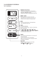
1.5 LOCATIONS OF CONTROLS
1.5.1 CONTROLS
TEMPERATURE SETTING
z This button can automatically control the temperature
of the room. The temperature can be set within a range of
60 F(16 C) to 86 F(30 C) by 1 F(1 C).
Select the lower number for lower temperature of the room.
ENERGY SAVER
The fan stops when the compressor stops cooling.
z Approximately every 3 minutes the fan will turn on and
check the room air to determine if cooling is needed.
MODE
z Everytime you push this button, it will toggle between
COOL, FAN, DRY or FAN, COOL.
Dry
Fan
Cool
TIMER
- STOPPING OPERATION
z Everytime you push this button, when the unit is operating,
timer is set as follows.
(1Hour 2Hours 3Hours 4Hours 5Hours 6Hours
7Hours 8Hours 9Hours 10Hours 11Hours 12Hours Cancel)
z The Setting Temperature will be raised by 2 F(1 C) 30min. later
and by 2 F(1 C) after another 30 min.
POWER
z To turn the unit ON, push the button. To turn the unit OFF,
push the button again.
z This button takes priority over any other buttons.
z When you first turn it on, the unit is on the High cool mode
and the temp. at 72 F(22 C).
FAN SPEED
z Everytime you push this button it is set as follows.
{High(F2)
{High(F3)
-4-
Low(F1)
Mid(F2)
High(F2)...} or
Low(F1) High(F3)...}.
1.5.2 REMOTE CONTROLLER
POWER
z To turn the Set ON, push the button. To turn the Set OFF, push the button again.
z This button takes priority over any other buttons.
z When you first turn it on, the Set is on the High cool mode and the temp. at 72� F(22� C).
TEMPERATURE SETTING
z This button can automatically control the temperature of the room.
Power
The temperature can be set within a range of 60� F(16� C) to
86� F(30� C) by 1� F(1� C).
Select the lower number for lower temperature of the room.
Temp
FAN SPEED
z Everytime you push this button it is set as follows.
{High(F2)
{High(F3)
Low(F1)
Mid(F2)
High(F2) or
Low(F1) High(F3)...}
Fan Speed
TIMER
- STOPPING OPERATION
z Everytime you push this button, when the set is operating,
timer is set as follows.
(1Hour 2Hours 3Hours 4Hours 5Hours 6Hours
7Hours 8Hours 9Hours 10Hours 11Hours 12Hours Cancel)
z The Setting Temperature will be raised by 2� F(1� C) 30min.
later and by 2� F(1� C) after another 30 min.
Timer
Mode
Energy
Saver
Auto
Swing
ENERGY SAVER
z The fan stops when the compressor stops cooling.
Approximately every 3 minutes the fan will turn on and
check the room air to determine if cooling is needed.
COOL/FAN/DRY or COOL/FAN
z Everytime you push this button, it will toggle between COOL, FAN and DRY.
How to Insert Batteries
z Do not use rechargeable batteries. Such bat-
1. Remove the cover from the back of the
teries
differ from standard dry cells in shape, dimensions, and performance.
remote controller
2. Insert two batteries.
z Be sure that the (+) and (-) directions
z Remove the batteries from the remote con-
are correct.
z Be sure that both batteries are new.
troller if the air conditioner is not going to be
used for an extended length of time.
3. Re-attach the cover.
-5-
2. DISASSEMBLY INSTRUCTIONS
2.1 MECHANICAL PARTS
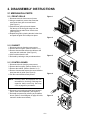
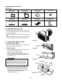
2.1.1 FRONT GRILLE
Figure 1
1. Disconnect the unit from source of power.
2. Using a screwdriver, remove the screw that
secures the front grille to control board.
(See Figure 1)
3. Push the front grille up from the bottom.
Pull the top of the front grille away from the
cabinet as the top tabs lift out of their slots.
(See Figure 2)
4. Replace the grille by placing the tabs in the slots
and push the grille until it snaps into place.
Figure 2
2.1.2 CABINET
1. Disconnect the unit from the power source.
2. Remove the front grille. (Refer to section 2.1.1)
3. Remove 9 screws that secure the cabinet to the
base pan and condenser. (See Figure 3)
4. Lift the cabinet from the unit.
5. Re-install by referring to the procedures above.
Figure 3
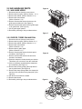
2.1.3 CONTROL BOARD
1. Disconnect the unit from the power source.
2. Remove the front grille. (Refer to Section 2.1.1)
3. Remove the cabinet. (Refer to Section 2.1.2)
4. Remove 2 screws that secure the control board to
base pan and air guide. (See Figure 4)
5. Pull the control board toward yourself.
Figure 4
NOTE : Controls, wires, and capacitor are now
accessible for servicing. Discharge the
capacitor before servicing. See step
2.3.3 on page 9 for procedures.
6. Disconnect one housing terminal and 3 wires for
the fan motor and compressor. (See Figure 5)
7. Re-install components by referring to procedures
above. (Refer to circuit diagram on page 26 in this
manual or inside control board.)
Figure 5
—6—
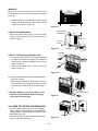
2.2 AIR HANDLING PARTS
Figure 6
2.2.1 AIR GUIDE UPPER
1. Disconnect the unit from the power source.
2. Remove the front grille. (Refer to Section 2.1.1)
3. Remove the cabinet. (Refer to Section 2.1.2)
4. Remove the control board.
(Refer to Section 2.1.3)
5. Remove 2 screws that secure the brace to air
guide upper and shroud. (See Figure 6)
6. Remove 2 screws that secure the air guide upper
to air guide lower. (See Figure 6)
7. Lift air guide upper upward.
8. Re-install by referring to the procedures above.
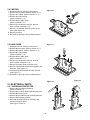
Figure 7
2.2.2 ORIFICE, TURBO FAN AND FAN
1. Disconnect the unit from the power source.
2. Remove the front grille. (Refer to Section 2.1.1)
3. Remove the cabinet. (Refer to Section 2.1.2)
4. Remove the control board.
(Refer to Section 2.1.3)
5. Remove the air guide upper.
(Refer to Section 2.2.1)
6. Remove 2 screws that secure the base pan to
condenser. (See Figure 7)
7. Remove 2 screws that secures the shroud to
channel of condenser.
8. Press the snap area of shroud with your thumbs.
This allows you to remove it from the condenser.
9. Lift the compressor upward with the evaporator
and condenser. (See Figure 7)
10. Remove the orfice by pushing the snap area of
the air guide blower. (See Figure 8)
11. Remove the clamp springs which are clamped to
the boss of fan and turbo fan by hand plier. (See
Figure 9)
12. Pull the fan and turbo fan outward.
13. Remove the shroud.
14. Re-install by referring to the procedures above.
Figure 8
Figure 9
—7—
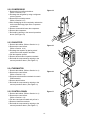
2.2.3 MOTOR
1. Disconnect the unit from the power source.
2. Remove the front grille. (Refer to Section 2.1.1)
3. Remove the cabinet. (Refer to Section 2.1.2)
4. Remove the control board.
(Refer to Section 2.1.3)
5. Remove the air guide upper.
(Refer to Section 2.2.1)
6. Remove the compressor, turbo fan, fan and
shroud. (Refer to Section 2.2.2)
7. Remove 2 screws that secure the motor to the
motor. (See Figure 10)
8. Remove the motor.
9. Re-install by referring to the procedures above.
2.2.4 AIR GUIDE
Figure 10
Figure 11
1. Disconnect the unit from the power source.
2. Remove the front grille. (Refer to Section 2.1.1)
3. Remove the cabinet. (Refer to Section 2.1.2)
4. Remove the control board.
(Refer to Section 2.1.3)
5. Remove the air guide upper.
(Refer to Section 2.2.1)
6. Remove the compressor, turbo fan, fan and
shroud. (Refer to Section 2.2.2)
7. Remove the motor. (Refer to Section 2.2.3)
8. Remove 2 screws that secure the air guide to the
base pan. (See Figure 11)
9. Push the air guide backward and lift it upward.
(See Figure 11)
10. Re-install by referring to the procedures above.
Figure 12
2.3 ELECTRICAL PARTS
2.3.1 OVERLOAD PROTECTOR
1. Remove the front grille and cabinet.
(Refer to Section 2.1)
2. Remove the nut which fastens the terminal cover.
3. Remove the terminal cover.
4. Remove all the leads from the overload protector.
5. Remove the overload protector.
6. Re-install the components by referring to the
removal procedure above.
(See Figure 12 and 13)
— 8—
Figure 13
2.3.2 COMPRESSOR
Figure 14
1. Remove the front grille and cabinet.
(Refer to Section 2.1.2)
2. Discharge the refrigerant by using a refrigerant
recovery system.
3. Remove the overload protector.
(Refer to Section 2.3.1)
4. After discharging the unit completely, unbrace the
suction and discharge pipes at the compressor
connections.
5. Remove 3 nuts which fasten the compressor.
6. Remove the compressor.
7. Re-install by referring to the removal procedure
above. (See Figure 14)
2.3.3 CAPACITOR
1. Remove the cabinet. (Refer to Section 2.1.2)
2. Remove the control board.
(Refer to Section 2.1.3)
3. Discharge the capacitor by placing a 20 K
resistor across the capacitor terminals.
4. Pull the capacitor upward.
5. Remove all the leads of capacitor terminals.
6. Re-install the components by referring to the
removal procedure above. (See Figure 15)
Figure 15
2.3.4 THERMISTOR
1. Remove the cabinet. (Refer to Section 2.1.2)
2. Remove the control board.
(Refer to Section 2.1.3)
3. Disconnect the thermistor terminals from main
P.W.B assembly.
4. Remove the thermistor.
5. Re-install the components by referring to the
removal procedure above. (See Figure 16)
Figure 16
Figure 17
2.3.5 CONTROL PANEL
1. Remove the cabinet. (Refer to Section 2.1.2)
2. Remove the control board.
(Refer to Section 2.1.3)
3. Pull the control panel forward and pull out it.
4. Remove 2 lead wire terminals.
5. Re-install the components by referring to the
removal procedure above. (See Figure 17)
- 9-
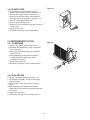
2.3.6 POWER CORD
Figure 18
1. Disconnect the unit from source of power.
2. Remove the front grille. (Refer to Section 2.1.1)
3. Remove the cabinet. (Refer to Section 2.1.2)
4. Remove 2 screws that secure control board to
base pan and air guide. (Refer to Section 2.1.3)
5. Pulls the control board toward you.
6. Remove the grounding screw.
7. Remove a screw securing the clip with cord to the
control board.
8. Pull the power cord.
9. Re-install by referring to procedures above.
2.4 REFRIGERANT CYCLE
Figure19
2.4.1 CONDENSER
1. Remove the cabinet. (Refer to Section 2.1.2)
2. Discharge the refrigerant by using a refrigerant
recovery system.
3. Remove 2 screws which fasten the condenser.
(See Figure 19)
4. After discharging the refrigerant completely,
unbraze the interconnecting tube at the
condenser connections.
5. Remove the condenser.
6. Re-install by referring to the procedures above.
2.4.2 EVAPORATOR
1. Remove the cabinet. (Refer to Section 2.1.2)
2. Discharge the refrigera
t by using a refrigerant
n
recovery system.
3. Remove the air guide upper. (Refer to Section
2.2.1)
4. After discharging the refrigerant completely,
unbraze the interconnecting tube at the evaporator
connections.
5. Remove the evaporator.
6. Re-install by referring to the procedures above.
- 10 -
2.4.3 CAPILLARY TUBE
1. Remove the cabinet. (Refer to Section 2.1.2)
2. Discharge the refrigerant by using a refrigerant
recovery system.
3. Remove the air guide upper. (Refer to Section
2.2.1)
4. After discharging the refrigerant completely,
unbraze the interconnecting tube of the capillary
tube.
5. Remove the capillary tube.
6. Re-install by referring to the procedures above.
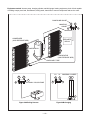
NOTES
Replacement of the refrigeration cycle.
1. When replacing the refrigerating cycle, be sure to
discharge the refrigerant by using a refrigerant
recovery system.
2. After discharging the unit completely, remove the
desired components, and unbraze the pinch-off
tubes.
3. Solder service valves into the pinch-off tube ports,
leaving the valves open.
4. Solder the pinch-off tubes with service valves.
5. After completing the above procedures, the valve
must be closed and left in place on the system for
any subsequent procedures.
6. Evacuate as follows:
6-1. Connect the vacuum pump, as illustrated in
figure 20A.
6-2. Start the vacuum pump. Slowly open manifold
valves A and B with two full turns counterclockwise and leave the valves closed.
The vacuum pump is now pulling through
valves A and B up to valve C by means of
manifold and the entire system.
6-4. Remove the hose from the vacuum pump and
place it on the charging cylinder. See figure
20B. Open valve C.
Discharge the line at the manifold connection.
6-5. The system is now ready for final charging.
7. Recharge as follows:
7-1. Rotary compressor systems are charged from
the high-side. If the total charge cannot be put
in the high-side, the balance will be put in the
suction line through the access valve which is
installed as the system is opened.
7-2. Connect the charging cylinder as shown in figure 20B. With valve C open, discharge the
hose at the manifold connection.
7-3. Open valve A and allow the proper charge to
enter the system. Valve B is still closed.
7-4. If more charge is required, the high-side will
not take it. Close valve A.
7-5. With the unit running, open valve B and add
the balance of the charge.
a. Do not add the liquid refrigerant to the lowside.
b. Watch the low-side gauge, allow pressure to
rise to 30 lbs.
c. Turn off valve B and allow the pressure to
drop.
d. Repeat steps B and C until the balance of
the charge is in the system.
7-6. When the unit is operating correctly, use the
pinch-off tool with the unit still running and the
clamp on the pinch-off tube. Using a tube cutter, cut the pinch-off tube about 2 inches from
the pinch-off tool. Use sil-fos solder and solder
the pinch-off tube closed. Turn off the unit,
allow setting for a while and then test the leakage of the pinch-off connection.
CAUTION : If high vacuum equipment is used,
just crack valves A and B for a few minutes, then
open slowly with the two full turns counter-clockwise. This will keep oil from foaming and being
drawn into the vacuum pump.
6-3. Operate the vacuum pump for 20 to 30 minutes, until 600 micron vacuum is obtained.
Close valves A and B and observe vacuum
gauge for a few minutes.
A rise in pressure would indicate a possible
leak or moisture remaining in the system.
With valves A and B closed, stop the vacuum
pump.
—11—
Equipment needed: Vacuum pump, charging cylinder, manifold gauge, brazing equipment, pinch-off tool capable
of making a vapor proof seal, leak detector, tubing cutter, hand tools to remove components and service valve.
COMPOUND GAUGE
MANIFOLD
GAUGE
CONDENSER
(HIGH PRESSURE SIDE)
B
A
SEE INSETS
BELOW
COMPRESSOR
EVAPORATOR
(LOW PRESSURE SIDE)
CAPILLARY TUBE
LO
A
B
EXTERNAL VACUUM PUMP
B
HI
CHARGING CYLINDER
A
C
Figure 20A-Pulling Vacuum
Figure 20B-Charging
—12—
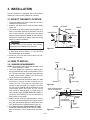
3. INSTALLATION
This air conditioner is designed with a button-down
chassis so it can be easily installed in a window.
3.1 SELECT THE BEST LOCATION
1. To prevent vibration and noise, make sure the unit is
installed securely and firmly.
2. Install the unit where the sun does not shine directly
on the unit.
3. The outside of the cabinet must extend outward for at
least 10" and there should be no obstacles, such as a
fence or wall, within 20" from the back of the cabinet
because it will prevent heat radiation of the condenser.
Restriction of outside air will greatly reduce the cooling
efficiency of the air conditioner.
INSIDE
AWNING
COOLED AIR
30"-60"
CAUTION
All side louvers of the cabinet must remain
exposed on the outdside of the structure.
4. Install the unit slanted slightly so the back is slightly lower than the front (about 1/4"). This will force
condensed water to the outside.
5. Install the unit with the bottom about 30"~60"
above the floor level.
3.2 HOW TO INSTALL
3.2.1 WINDOW REQUIREMENTS
OUTSIDE
FENCE
HEAT
RADIATION
ABOUT 1/4 "
Over 20"
Figure 21
INNER
SILL
NOTE: All supporting parts should be secured to firm
wood, masonry, or metal.
1. This unit is designed for installation in standard double hung windows with actual opening widths of 22" to
36". The upper and lower sash must open sufficiently
to allow a clear vertical opening of 13" from the botOUTER
tom of the sash to the window stool.
SILL
2.If storm window presents interference, fasten a 2" wide
wood strip to the inner window sill across the full
INDOORS
OUTDOORS
width of the sill. The wood strip should be thick
Figure 22
enough to raise the height of the window sill so that
the unit can be installed without interference by the
1" MAX.
WOOD STRIP MOUNTED
storm window frame. See Figure. 23. Top of wood
3/4"
ON TOP OF INNER SILL
strip should be approximately 3/4" higher than the
CLEARANCE
storm window frame (STORM WINDOW FRAME) or
wood strip (OUTDOORS) to help condensation to
STORM
WINDOW
drain properly to the outside.
INNER
FRAME
3. Install a second wood strip (approximately 6" long by
SILL
WOOD STRIP
11/2" wide and same thickness as first strip) in the cenFOR L BRACKET
ter of the outer sill flush against the back off the inner
OUTER
sill. This will raise the L bracket as shown Figure. 23.
SILL
4. If the distance between STORM WINDOW FRAME
INDOORS
OUTDOORS
and WOOD STRIP MOUNTED ON TOP OF INNER
Figure 23
SILL is more than 1", two of wood strip are not necessary.
—13—
Installation Kit (Some models)
HARDWARE
TYPE B: 5EA
(WOOD SCREW)
TYPE C: 3EA
(L BACKET)
DRAIN PIPE
16mm
10mm
TYPE A: 11EA
(SHORT SCREW)
TYPE D: 1EA
(SEAL STRIP)
TYPE E: 1EA
(SASH SEAL)
(Adhesive backed)
(Not adhesive backed)
TYPE F: 2EA
(GUIDE PANEL)
TYPE G: 1EA
(SUPPORT BACKET)
3.2.2 BEFORE INSTALLATION
1. Insert the guide panels into the guides of the air conditioner. Fasten the curtains to the unit with screws (TYPE
A), as shown Figure. 24.
2. Cut the adhesive-backed seal strip (TYPE D) to the window
width.
Remove the backing from the seal strip and attach the seal
strip to the underside of the bottom window. (Figure. 25)
TYPE A
Figure 24
3.2.3 NOW START INSTALLATION
1. LOCATING UNIT IN WINDOW
Open the window and mark center line on the center of
the inner sill, as shown in Figure. 26.
2. ATTACH L BRACKET
a. Install the L brackets behind the inner window sill, with
the short side of bracket as shown.
Use the 2 screws (TYPE A) provided.
b. The bracket helps to hold unit securely in place. Be
sure to place bracket edge flush against back of inner
sill. See Figure. 27.
CAUTION
During the following step, hold unit firmly until
window sash is lowered to top channel behind
side panel frames. Personal injury or property
damage may result if unit falls from window.
3. INSTALL THE AIR CONDITIONER IN THE WINDOW
a. Carefully lift the air conditioner and slide it into the
open window. Make sure the bottom guide of the air
conditioner drops into the notches of the
L bracket. See Figure. 27.
TYPE C
SEAL STRIP
(TYPE D)
Figure 25
CENTER LINE
INNER SILL
ROOM SIDE
Figure 26
INNER SILL
TYPE A
OUTER SILL
INSIDE
CENTER LINE
8"
8"
Figure 27
OUTSIDE
L BRACKET
—14—
IMPORTANT :
When the air conditioner drops into the L bracket, the air
conditioner will be centered in window opening as shown in
Figure. 28.
b. While steadying the air conditioner, carefully bring the
window sash down behind the upper guide of the air
conditioner, as shown in Figure. 29.
CENTER LINE
Figure 28
WINDOW FRAME
UPPER GUIDE
4. SECURE THE GUIDE PANELS
Extend the guide panels (TYPE F) to fill the window
opening using 4 screws (TYPE B) to secure them, as
shown in Figure. 30.
SEAL
ABOUT 1/4"
BOTTOM
GUIDE
Figure 29
L BRACKET
L BRACKET
TYPE A
5. INSTALL THE SASH SEAL AND SASH LOCK
a. Cut the sash seal (TYPE E) to the window width. Stuff
the sash seal between the glass and the window to
prevent air and insects from getting into the room, as
shown in Figure. 30.
b. Fasten the L bracket using a (TYPE A) screw, as
shown in Figure. 30.
SASH SEAL
(TYPE E)
TYPE B
Figure 30
6. a. Remove the screws that secure the cabinet and base
pan in the right side.
b. Fasten the suport bracket (TYPE G) using a removed
screw. Attach the suport bracket (TYPE G) in the inner
window sill with a screw (TYPE B), as shown Figure.
31.
7. Window installation of room air conditioner is now
completed. See ELECTRICAL DATA for attaching
power cord to electrical outlet.
TYPE B
Support Bracket (TYPE G)
Figure 31
1 hang
3.2.4 HOW TO SECURE THE DRAIN PIPE
In humid weather, excess water may cause the BASE
PAN to overflow. To drain the water, remove the DRAIN
CAP and secure the DRAIN PIPE to the rear hole of the
BASE PAN. (Figure. 32)
Press the drain pipe into the hole by pushing down and
away from the fins to avoid injury.
DRAIN CAP
DRAIN PIPE
Figure 32
—15—
2 push
REMOVAL FROM WINDOW
Turn the air conditioner off, disconnect the power cord, remove the L bracket, the screws and support bracket installed through
the top and bottom of the guide panels, and save for reinstallation later. Close the guide panels. Keeping a firm grip on the air
conditioner, raise the sash, and carefully tilt the air conditioner backward, draining any condensate. Lift the air conditioner from
the window and remove the sash seal from between the windows.
3.3 ELECTRICAL DATA
Line Cord Plug
Use Wall Receptacle
Do not under any
circumstances cut
or remove the
grounding prong
from the plug.
Power supply cord with
3-prong grounding plug
Power Supply
Use 15 AMP, time
delay fuse or circuit
breaker.
Standard 125V, 3-wire grounding
receptacle rated 15A, 125V AC
Power cord may include a current interrupter device. A test and reset button is provided on the plug case. The device should be tested
on a periodic basis by first pressing the TEST button and the RESET button. If the TEST button does not trip or if the RESET button
will not stay engaged, discontinue use of the air conditioner andcontact a qualified service technician.
USE OF EXTENSION CORDS
Because of potential safety hazards, we strongly discourage the use of an extension cord. However, if you wish to use an extension
cord, use a CSA certified/UL-listed 3-wire (grounding) extension cord, rated 15A, 125V.
4. TROUBLESHOOTING GUIDE
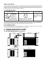
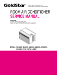
4.1 OUTSIDE DIMENSIONS (unit: mm [in])
29 (1 5/32")
370 (14 9/16")
42 (1 21/32")
472 (18 9/16")
42 (1 21/32")
120 (4 3/4")
12
(0.4 1/16")
312 (12 1/4")
346 (13 5/8")
27.5 (1 3/32")
22.5(0.8 3/32")
155(6 3/32")
370 (14 9/16")
312 (12 1/4")
472 (18 9/16")
- 16 -
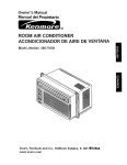
4.2 PIPING SYSTEM
CONDENSER COILS
FAN
MOTOR
CAPILLARY
TUBE
TURBO FAN
EVAPORATOR
COILS
Following is a brief description of the important components and their function in what is called the refrigeration
system. Reference should be made to Figure 33 to follow the refrigerating cycle and the flow of the refrigerant in
the cooling cycle.
ROOM AIR CONDITIONER
CYCLE OF REFRIGERATION
EVAPORATOR COILS
CONDENSER COILS
SUCTION LINE
COOL LOW PRESSURE VAPOR
COMPLETE LIQUID
BOIL OFF POINT
COOLED
AIR
VAPOR INLET
HOT
DISCHARGED
AIR
ROOM AIR HEAT LOAD
OUTSIDE COOLING
AIR FOR REFRIGERANT
PASS THROUGH
MOTOR
COMPRESSOR
DISCHARGE
LINE
NOT HIGH PRESSURE
VAPOR
OIL
LIQUID
PRESSURE
DROP
LIQUID OUTLET
(LIQUID REFRIGERANT)
CAPILLARY TUBE
HIGH PRESSURE VAPOR
LIQUID REFRIGERANT
LOW PRESSURE VAPOR
Figure 33
—17—
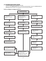
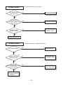
4.3 TROUBLESHOOTING GUIDE
In general, possible trouble is classified in two kinds.
The one is called Starting Failure which is caused by an electrical defect. The other is Ineffective Air Conditioning caused by a defect in the refrigeration circuit and improper application.
Unit is running but cooling is ineffective.
Ineffective Cooling
Check cold air
circulation for smooth
flow.
Check outdoor coil
(heat exchanger) and
fan operation.
Dirty indoor coil
(heat exchanger)
Check gas leakage.
Repair gas leak.
Check heat load
increase.
Clean condenser.
Not on separate circuit
Malfunction of fan.
Clogging of air filter.
Replacement of unit if
the unit is beyond repair.
Check inside gas
pressure.
Adjust refrigerant
charge.
Obstruction at air outlet.
Remove obstruction.
Malfunction of
compressor.
Check clogging in refrigeration circuit.
Replacement of
compressor.
Repair clogging in
refrigeration circuit.
Satisfactory operation
with temperature
difference of inlet & outlet
air; 44~50°F (7~10°C)
—18—
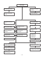
Fails to Start
Check of power source.
Check of circuit breaker
and fuse.
Check of control panel
setting.
Check control panel.
Compressor fails only to
start.
Fan only fails to start.
Drop of power voltage.
Improper thermistor
setting
Defect of compressor
capacitor.
Loose terminal
connection
Capacitor check.
Improper wiring
Improper wiring.
Defect of fan motor
capacitor.
Irregular motor
resistance (Ω)
Irregular motor
insulation (Ω)
Replacement.
Replacement of fan motor.
Irregular motor resistance (Ω)
Regular but fails to start.
Irregular motor insulation (Ω)
Replacement of compressor.
(Locking of piston, metal.)
Replacement of compressor
(Motor damaged).
—19—
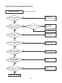
ELECTRIC PARTS TROUBLESHOOTING GUIDE:
Possible Trouble 1
Is the Trans output power
AC 115V?
• The unit does not operate.
NO
• Check the Fuse.
• Check the wiring diagram.
YES
Is the Trans output power
about AC 14V?
NO
Is shorted the Trans. output?
YES
Is output Voltage of IC01D
DC 12V?
YES
NO
• Check the Main
P.W.B pattern.
• Exchange the Trans.
• Exchange D02D~D05D.
• Exchange IC01D.
NO
YES
Is output Voltage of IC02D
DC 5V?
NO
• Exchange IC02D.
YES
Is the reset circuit all right?
(The No.14 of Micom
is 5V.)
NO
• Exchange IC01A.
YES
Is the
connection between
Main and Display
all right?
NO
• Connect connector
exactly.
NO
• Check the P.W.B
pattern.
YES
Is the voltage No.18 of Micom
DC 5V?
YES
Exchange Main P.W.B Ass'y.
—20—
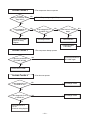
Possible Trouble 2
• The compressor does not operate.
Is Temp.
NO
setting set lower than Room
Temp.-0.5°C?
• Set the Temp. setting to higher Temp.
YES
Is the voltage No.10
of IC01M 0V?
NO
Is the voltage N0.7 of
IC01M DC 5V?
NO
YES
YES
• Check the RY-COMP.
• Check the wiring
Diagram.
• Exchange IC01M.
Is the Unit for 3 minutes
delay?
NO
YES
• Wait 3 Minutes
• Exchange MAIN
P.W.B Ass'y.
Possible Trouble 3
Is the wire connection of
RY-COMP all right?
• The compressor always operate.
• Connect LEAD Wire to
RY-COMP again.
NO
YES
• Check the RY-COMP.
Possible Trouble 4
Is the voltage NO.1 or 4
of IC01M DC 5V?
• Fan does not operate.
NO
• Exchange IC01M.
YES
Is the voltage NO.13 or 16
of IC01M 0V?
NO
• Exchange IC01M.
YES
• Check the RY-Hi or
RY-Lo.
• Check the wiring diagram.
—21—
• Romote controller does not operate.
Possible Trouble 5
Is the voltage of Battery
about over 2.3V?
NO
• Exchange the battery.
YES
Is the voltage No.16
of CN-DISP1 on Main P.W.B
Ass'y DC 5V?
NO
• Check the P.W.B pattern.
YES
Is the connection of
CN-DISP1 all right?
• Connect connector to
CN-DISP1 exactly.
NO
YES
• Exchange Receiver Ass'y.
Possible Trouble 6
Is the IC01G all right?
• It displays abnormally on Display P.W.B Ass'y.
NO
• Exchange IC01G.
YES
NO
Is the connection of
CN-DISP1 all right?
• Connect connector
to CN-DISP1 exactly.
NO
YES
Does the Q01G,
Q02G, Q03G Q04G operate normally
on main P.W.B Ass'y?
NO
• Exchange Q01G,
Q02G, Q03G, Q04G
YES
• Exchange the display
P.W.B Ass'y.
—22—
ROOM AIR CONDITIONER VOLTAGE LIMITS
NAME PLATE RATING
MINIMUM
MAXIMUM
115V ± 10%
103.5V
126.5V
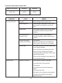
COMPLAINT
Fan motor will not run.
CAUSE
REMEDY
No power
Check voltage at outlet. Correct if none.
Power supply cord
Check voltage to rotary switch. If none, check
power supply cord. Replace cord if circuit is
open.
Rotary switch
Check switch continuity. Refer to wiring diagram
for terminal identification. Replace switch if
defective.
Wire disconnected or
connection loose
Connect wire. Refer to wiring diagram for
terminal identification. Repair or replace loose
terminal.
Capacitor (Discharge
capacitor before testing.)
Test capacitor.
Replace if not within ±10% of manufacturer's
rating. Replace if shorted, open, or damaged.
Will not rotate
Fan blade hitting shroud or blower wheel hitting
scroll. Re-align assembly.
Units using slinger ring condenser fans must
have 0.22~0.25 inch clearance to the base.
If necessary, shim up the bottom of the fan motor
with mounting screw(s).
Check fan motor bearings; if motor shaft will not
rotate, replace the motor.
Fan motor runs.
Revolves on overload
Check voltage. See limits on this page.
If not within limits, call an electrician.
Test capacitor.
Check bearings. Does the fan blade rotate
freely?
If not, replace fan motor.
Pay attention to any change from high speed to
low speed. If the speed does not change,
replace the motor.
—23—
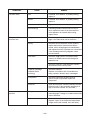
COMPLAINT
Fan motor noise.
Compressor will not run,
fan motor runs.
CAUSE
REMEDY
Fan
If cracked, out of balance, or partially missing,
replace it.
Blower
If cracked, out of balance, or partially missing,
replace it.
Loose set screw
Tighten it.
Worn bearings
If knocking sounds continue when running or
loose, replace the motor. If the motor hums or
noise appears to be internal while running,
replace motor.
Voltage
Check voltage. See the limits on the preceding
page. If not within limits, call an electrician.
Wiring
Check the wire connections; if loose, repair or
replace the terminal. If the wires are disconnected, refer to wiring diagram for identification,
and replace the wires. Check the wire connections;
If not according to the wiring diagram, correct
the connections.
Thermistor
Check the TEMP control. If not at the lowest
number, set TEMP control to this setting and
restart the unit.
Check the continuity of the thermistor. Replace
the thermistor if the circuit is open.
Compressor cycles on
overload.
Capacitor (discharge
capacitor before
servicing.)
Check the capacitor.
Replace if not within ±10% of manufacturer’s
rating, replace if shorted, open, or damaged.
Compressor
Check the compressor for open circuit or
ground. If open or grounded, replace the
compressor.
Overload
Check the compressor overload if externally mounted.
Replace if open. (If the compressor temperature is
high, remove the overload, cool, and retest.)
Voltage
Check the voltage. See the limits on the
preceding page. If voltage is not within these limits,
call an electrician.
Overload
Check overload, if externally mounted.
Replace if open. (If the compressor temperature
is high, remove the overload, cool, and retest.)
—24—
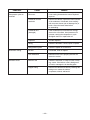
COMPLAINT
Compressor cycles on
overload
Insufficient cooling.
Excessive noise.
CAUSE
REMEDY
Fan motor
If not running, determine the cause. Replace if
required.
Condenser air flow
restriction
Remove the cabinet, inspect the interior surface
of the condenser. If restricted, clean carefully
with a vacuum cleaner (do not damage fins) or
brush. Clean the interior base before
re-assembling.
Condenser fins
(damaged)
If the condenser fins are closed over a large
area on the coil surface, head pressures will
increase, causing the compressor to cycle.
Straighten the fins or replace the coil.
Capacitor
Test the capacitor.
Wiring
Check the terminals. If loose, repair or replace.
Refrigeration system
Check the system for a restriction.
Air filter
If restricted, clean or replace.
Unit undersized
Determine if the unit is properly sized for the
area to be cooled.
Blower or fan
Check the set screw, or clamp. If loose or missing, correct. If the blower or fan is hitting scroll
or barrier, rearrange the air handling parts.
Copper tubing
Remove the cabinet and carefully rearrange the
tubing not to contact the cabinet,
compressor, shroud, and barrier.
—25—
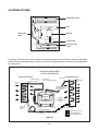
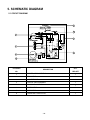
5. SCHEMATIC DIAGRAM
5.1 CIRCUIT DIAGRAM
1
6
2
4
7
5
3
8
LOCATION
DESCRIPTION
NO.
Q'TY
PER SET
1
POWER CORD ASSEMBLY
1
2
FAN MOTOR
1
3
COMPRESSOR
1
4
DISPLAY P.W.B ASSEMBLY
1
5
MAIN P.W.B ASSEMBLY
1
6
THERMISTOR
1
7
CAPACITOR
1
8
OVERLOAD PROTECTOR
1
- 26 -
—27—
MAIN POWER
FAN
COMP
HERM
C
CAPACITOR
FAN
MOTOR
S/V4WAY
SYNC
MOTOR
PIPE-TH
ROOM-TH
1
1
CN-BK
CN-BL
CN-RD
250V/T2A
FUSE
RY-COMP
G4A-1A-E-LG
12V
CN-4WAY
CN-SYNC
CN-WOR
3
3
1
1
2
4
3
3
2
2
4
3
1
1
SMW250-02
R 01J
120 1/2W
SVC271D-14A
ZNR01J
C 01J
0.1/275V
R Y -H I
RY-MED
RY-LOW
RY-4WAY
RY-SYNC
0K
R 03H
2
1
4
7
6
3
R 22H
OR2H
12.1K
1%
1000
35V
D04D
+
C01D
D 05D
IC01M
8
9
ULN2004A
1
2
14
16
15
4
13
5
11
12
7
10
D02D~D05D
1N4004
D 03D
D02D
12V
OR1H
POWER TRANS
RY-HI
RY-MED
R Y - L OW
RY-4WAY
RY-SYNC
RY-COMP
12.1K
1%
R21H
5V
1000
16V
I
+
12.1K
1%
R01H
C03D
7812
IC01D
C02D
0.1
50V
O
6.2K
1%
R02H
C04D
7805
IC 0 2 D
0.01
50V
O
12V
LED out3
Buzzer
Receiver
HI
M ED
ION
HV B
LOW
4WAY
SYNC
COMP
34
22
I
C05D +
220
10V
33
32
31
30
29
28
27
26
25
24
23
RT8.00MG
Option2
LED out2
CN-TH1
1M
R01B
36
20
37
5V
5V
17
16
38
39
R02E
20
R12F
20K
40
MICOM
18
TMP87CH47U
19
C 06D
0.01
50V
R01E
1K
5V
35
21
Option1
LED out1
VAref
KEY0
Room TH
KEY1
VSS
SLIDE SW
Pipe TH
LED out0
Osc out
VDD
41
15
42
14
/Reset
SEG-f
Osc in
SEG-g
43
1
2
3
4
5
6
7
8
9
10
11
C01L
680pF
4
SDA
Rx
2
1
+
3
WP
6
7
Vcc 8
SC L
1K
R01L
IC 0 1 G
ULN2004A
C01F R01F
0.001 10K
SEG-c
SEG-b
SEG-a
Digit0 (Scan0)
Digit1 (Scan1)
Digit2 (Scan2)
Digit3 (Scan3)
1
2
3 .6 V
GND SDA 5
A2
A1
A0
EEPROM
3
CAT93C46
1uF
10V
C02A
20K
R01A
Digit4 (Scan4)
SCL
C02F R02F
0 . 0 01 1 0 K
44
12
Tx
C01A
0.01
50V
13
TEST
SEG-e
OSC01B
SEG-d
5V
10
7
8
9
11
6
12
13
5
14
4
15
16
3
2
1
1K
R04P
20K
R02P
IC 0 1 A
5V
S7136
20K
R03P
12V
5V
R07G
R06G
R05G
R04G
R03G
R02G
R01G
CN-DISP
220
220
220
220
220
220
220
5V
16
15
12
11
10
9
8
7
6
14
A/RESTART
A/SWING
SW3
AIR PURIFIER
5V
CN-DISP
2
3
6
7
8
9
10
11
12
5
4
17
1
13
1
17
D 03F
ENERGY
SAVER
D07F
SW7
TEMP UP
Q 04G
A101S
2
16
COOL
SW2
SW5
PKM13EPY
-4002
BZ01E
E/SAVER
FAN
TIMER
DRY/HEAT
DEFROST
D02F
TIMER
D05F
TEMP DOWN
A101S
Q 03G
3
15
d
c
b
V cc
GN D
RECEIVER
Vout
g
7 f
8
SW1
Digit1
a
1 e
2
3
4
5
D01F
FAN
D 04F
SW4
MODE
A101S
Q0 2 G
4
SW 6
d
c
e
f
Digit0
SW8
+
5V
C22L
220
10V
5
d
g
a
6
13
88 SEGMENT
e
g
a
b
D08F
10
f
D 06F
ON/OFF
AUTO SWING
14
A101S
Q0 1 G
c
b
5V
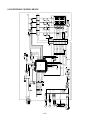
5.2 ELECTRONIC CONTROL DEVICE
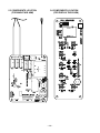
5.3 COMPONENTS LOCATION
(FOR MAIN P.W.B ASM)
5.4 COMPONENTS LOCATION
(FOR DISPLAY P.W.B ASM)
—28—
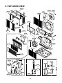
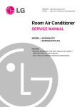
6. EXPLODED VIEW
137215
559010
130910
W48602
148000
554030
149980
349480
132111-2
267110
132111-1
135312
352390-2
159900-2
145200
359012
346811
W48602
352390-1
159900-1
152302
354210
130410
135313
264110
W0CZZ
552111
352115
567502
352113
554160
268714
263230
249950
238310 268712
35211A
550140
- 29 -
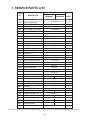
7. SERVICE PARTS LIST
PART NO
LOCATION
NO
DESCRIPTION
GWHD6500R
GWHD6500RY6
REMARKS
BASE ASSEMBLY,SINGLE
3041A10011E
R
130910
CABINET ASSEMBLY,SINGLE
3091A30016C
132111-1
FRAME ASSEMBLY
3211AR3239A
R
R
132111-2
FRAME ASSEMBLY
3211AR3239B
R
135312
GRILLE ASSEMBLY, FRONT(SINGLE)
3531AR1644H
135313
GRILLE ASSEMBLY, INLET
3530A10039A
R
R
137215
GUIDE
5210AR3196C
R
145200
LINK
4520AR3191A
R
148000
BRACE
4800A30003A
R
149980
SHROUD
4998A10008A
R
152302
FILTER(MECH),A/C
5231AR2148G
R
159900-1
VANE,VERTICAL
5990AR3190C
R
159900-2
VANE,VERTICAL
5990AR3190D
R
238310
ESCUTCHEON
3831A10001F
R
249950
CONTROL BOX, SINGLE
4994A20020A
R
263230
THERMISTOR ASSEMBLY
6323A20003D
R
264110
POWER CORD ASSEMBLY
6411A20048Y
R
267110
REMOTE CONTROLLER ASSEMBLY
6711A90019A
R
268712
PWB(PCB) ASSEMBLY, DISPLAY
6871A20193B
R
268714
PWB(PCB) ASSEMBLY, MAIN
6871A20188L
R
346811
MOTOR ASSEMBLY,SINGLE
4681A10002U
R
349480
ORIFICE
4948A10007A
R
352113
TUBE,DISCHARGE
5210A21100A
R
352115
TUBE ASSEMBLY, EVAPORATOR IN
R
35211A
352390-2
TUBE ASSEMBLY, SUCTION SINGLE
AIR GUIDE (Upper)
5211A10063C
5211A10062C
5211A30874A
5238A20004B
R
352390-1
AIR GUIDE (Lower)
5238A20003A
R
354210
EVAPORATOR ASSEMBLY, FIRST
5421A20016G
R
359012
FAN, TURBO
5900A10005A
R
550140
ISOLATOR,COMPRESSOR
5040AR4195A
R
552111
TUBE ASSEMBLY, CAPILLARY
554030
CONDENSER ASSEMBLY, FIRST
554160
COMPRESSOR SET
559010
FAN PROPELLER
567502
W0CZZ
O.L.P
CAPACITOR, DRA WING
W48602
CLAMP, SPRING
130410
5211A30793D
5211A30793C
5403A20009E
R
R
R
2520AA1C71A
R
R
6750U-L058A
6750A90016A
R
0CZZA20001W
6120AR2359V
R
2520UCEA004
5900A20017A
3H02932B
R
NOTE) *Please ensure GCSC since these parts may be changed depending upon the buyer's request. (GCSC WEBSITE http://biz.lgservice.com)
_ 30 _
P/No.: 3828A20529B
October, 2005
Printed inThailand