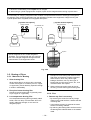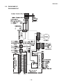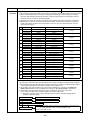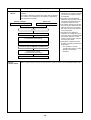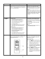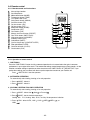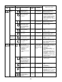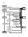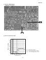
1
FILE NO. SVM-07034-2 !""#! Indoor Unit <High Wall, Heat Pump Type> RAS-M07SKV-E RAS-M10SKV-E RAS-M13SKV-E RAS-M16SKV-E <High Wall, Cooling Type> RAS-M10SKCV-E RAS-M13SKCV-E RAS-M16SKCV-E R410A Revised May, 2009 CONTENTS 1. SAFETY PRECAUTIONS .......................................................................... 3 2. SPECIFICATIONS ..................................................................................... 5 3. REFRIGERANT R410A ............................................................................. 8 4. CONSTRUCTION VIEWS ........................................................................ 16 5. WIRING DIAGRAM .................................................................................. 17 6. SPECIFICATIONS OF ELECTRICAL PARTS ......................................... 19 7. REFRIGERANT CYCLE DIAGRAM ........................................................ 20 8. CONTROL BLOCK DIAGRAM ................................................................ 21 9. OPERATION DESCRIPTION ................................................................... 23 10. INSTALLATION PROCEDURE ................................................................ 47 11. HOW TO DIAGNOSE THE TROUBLE ...................................................... 55 12. HOW TO REPLACE THE MAIN PARTS ................................................... 74 13. EXPLODED VIEWS AND PARTS LIST ................................................... 83 –2– 1. SAFETY PRECAUTIONS For general public use Power supply cord of outdoor unit shall be more than 1.5 mm2 (H07RN-F or 60245IEC66) polychloroprene sheathed flexible cord. • • • • Read this “SAFETY PRECAUTIONS” carefully before servicing. The precautions described below include the important items regarding safety. Observe them without fail. After the servicing work, perform a trial operation to check for any problem. Turn off the main power supply switch (or breaker) before the unit maintenance. CAUTION New Refrigerant Air Conditioner Installation • THIS AIR CONDITIONER ADOPTS THE NEW HFC REFRIGERANT (R410A) WHICH DOES NOT DESTROY OZONE LAYER. R410A refrigerant is apt to be affected by impurities such as water, oxidizing membrane, and oils because the working pressure of R410A refrigerant is approx. 1.6 times of refrigerant R22. Accompanied with the adoption of the new refrigerant, the refrigeration machine oil has also been changed. Therefore, during installation work, be sure that water, dust, former refrigerant, or refrigeration machine oil does not enter into the new type refrigerant R410A air conditioner circuit. To prevent mixing of refrigerant or refrigerating machine oil, the sizes of connecting sections of charging port on main unit and installation tools are different from those used for the conventional refrigerant units. Accordingly, special tools are required for the new refrigerant (R410A) units. For connecting pipes, use new and clean piping materials with high pressure fittings made for R410A only, so that water and/or dust does not enter. Moreover, do not use the existing piping because there are some problems with pressure fittings and possible impurities in existing piping. CAUTION TO DISCONNECT THE APPLIANCE FROM THE MAIN POWER SUPPLY This appliance must be connected to the main power supply by a circuit breaker or a switch with a contact separation of at least 3 mm. DANGER • ASK AN AUTHORIZED DEALER OR QUALIFIED INSTALLATION PROFESSIONAL TO INSTALL/MAINTAIN THE AIR CONDITIONER. INAPPROPRIATE SERVICING MAY RESULT IN WATER LEAKAGE, ELECTRIC SHOCK OR FIRE. • TURN OFF MAIN POWER SUPPLY BEFORE ATTEMPTING ANY ELECTRICAL WORK. MAKE SURE ALL POWER SWITCHES ARE OFF. FAILURE TO DO SO MAY CAUSE ELECTRIC SHOCK. DANGER: HIGH VOLTAGE The high voltage circuit is incorporated. Be careful to do the check service, as the electric shock may be caused in case of touching parts on the P.C. board by hand. • CORRECTLY CONNECT THE CONNECTING CABLE. IF THE CONNECTING CABLE IS INCORRECTLY CONNECTED, ELECTRIC PARTS MAY BE DAMAGED. • CHECK THAT THE EARTH WIRE IS NOT BROKEN OR DISCONNECTED BEFORE SERVICE AND INSTALLATION. FAILURE TO DO SO MAY CAUSE ELECTRIC SHOCK. –3– • DO NOT INSTALL NEAR CONCENTRATIONS OF COMBUSTIBLE GAS OR GAS VAPORS. FAILURE TO FOLLOW THIS INSTRUCTION CAN RESULT IN FIRE OR EXPLOSION. • TO PREVENT THE INDOOR UNIT FROM OVERHEATING AND CAUSING A FIRE HAZARD, PLACE THE UNIT WELL AWAY (MORE THAN 2 M) FROM HEAT SOURCES SUCH AS RADIATORS, HEAT REGISTORS, FURNACE, STOVES, ETC. • WHEN MOVING THE AIR-CONDITIONER FOR INSTALLATION IN ANOTHER PLACE, BE VERY CAREFUL NOT TO ALLOW THE SPECIFIED REFRIGERANT (R410A) TO BECOME MIXED WITH ANY OTHER GASEOUS BODY INTO THE REFRIGERATION CIRCUIT. IF AIR OR ANY OTHER GAS IS MIXED IN THE REFRIGERANT, THE GAS PRESSURE IN THE REFRIGERATION CIRCUIT WILL BECOME ABNORMALLY HIGH AND IT MAY RESULT IN THE PIPE BURSTING AND POSSIBLE PERSONNEL INJURIES. • IN THE EVENT THAT THE REFRIGERANT GAS LEAKS OUT OF THE PIPE DURING THE SERVICE WORK AND THE INSTALLATION WORK, IMMEDIATELY LET FRESH AIR INTO THE ROOM. IF THE REFRIGERANT GAS IS HEATED, SUCH AS BY FIRE, GENERATION OF POISONOUS GAS MAY RESULT. WARNING • Never modify this unit by removing any of the safety guards or bypass any of the safety interlock switches. • Do not install in a place which cannot bear the weight of the unit. Personal injury and property damage can result if the unit falls. • After the installation work, confirm that refrigerant gas does not leak. If refrigerant gas leaks into the room and flows near a fire source, such as a cooking range, noxious gas may generate. • The electrical work must be performed by a qualified electrician in accordance with the Installation Manual. Make sure the air conditioner uses an exclusive circuit. An insufficient circuit capacity or inappropriate installation may cause fire. • When wiring, use the specified cables and connect the terminals securely to prevent external forces applied to the cable from affecting the terminals. • Be sure to provide grounding. Do not connect ground wires to gas pipes, water pipes, lightning rods or ground wires for telephone cables. • Conform to the regulations of the local electric company when wiring the power supply. Inappropriate grounding may cause electric shock. CAUTION • Exposure of unit to water or other moisture before installation may result in an electrical short. Do not store in a wet basement or expose to rain or water. • Do not install in a place that can increase the vibration of the unit. Do not install in a place that can amplify the noise level of the unit or where noise or discharged air might disturb neighbors. • To avoid personal injury, be careful when handling parts with sharp edges. • Perform the specified installation work to guard against an earthquake. If the air conditioner is not installed appropriately, accidents may occur due to the falling unit. For Reference: If a heating operation would be continuously performed for a long time under the condition that the outdoor temperature is 0°C or lower, drainage of defrosted water may be difficult due to freezing of the bottom plate, resulting in a trouble of the cabinet or fan. It is recommended to procure an antifreeze heater locally for a safe installation of the air conditioner. For details, contact the dealer. –4– Revised-2 2. Specifications 2-1. Combined Outdoor Unit The outdoor units, which can be combined with M**SKV-E series indoor unit are as described below: 2-2-1. Heatpump type Outdoor Combined outdoor unit unit type model name M16SKV-E 2-room Multi RAS-M14GAV-E X outdoor unit RAS-M18GAV-E X 3-room Multi RAS-3M18SAV-E X outdoor unit RAS-3M26GAV-E1 4-room Multi RAS-4M23SAV-E outdoor unit RAS-4M27GAV-E1 Indoor unit model name M13SKV-E M10SKV-E M07SKV-E X X : Combination available X : Combination unavailable 2-2-2. Cooling only type Outdoor Combined outdoor unit unit type model name M16SKCV-E 2-room Multi RAS-M14GACV-E X outdoor unit RAS-M18GACV-E 3-room Multi RAS-3M18SACV-E outdoor unit RAS-3M23GACV-E 4-room Multi RAS-4M23SACV-E outdoor unit RAS-4M27GACV-E Indoor unit model name M13SKCV-E M10SKCV-E : Combination available X : Combination unavailable This service manual describes about M**SKV-E series indoor units, RAS-M07SKV-E,RAS-M10SKV-E, RAS-M13SKV-E,RAS-M16SKV-E,RAS-M10SKCV-E,RAS-M13SKCV-E and RAS-M16SKCV-E only. For the multi outdoor unit to be combined, refer to the service manual. Outdoor unit Heat Pump Model Cooling only model RAS-M14GAV-E RAS-M14GACV-E RAS-M18GAV-E RAS-M18GACV-E RAS-3M18SAV-E File name A05-009-1 RAS-3M18SACV-E A06-013 RAS-3M23GACV-E A05-014-1 RAS-4M23SAV-E RAS-4M23SACV-E A06-014 RAS-3M26GAV-E,RAS-4M27GAV-E RAS-4M27GACV-E A05-011-1 –5– Revised-2 Specifications Unit model Indoor Outdoor Cooling capacity Cooling capacity range Heating capacity Heating capacity range Power supply Electric Indoor characteristic Outdoor COP(Cooling/Heating) Indoor Operating noise (Cooling/ dB(A) Heating) Outdoor Indoor unit Outdoor unit Piping connection Unit model Dimension (mm) (kW) (kW) (kW) (kW) Unit model Running current Power consumption Power factor Operation mode Running current Power consumption Power factor Starting current (A) (W) (%) (A) (W) (%) (A) Unit model High Medium Low Cooling Heating Height Width Depth Net weight Fan motor output Air flow rate (m3/h) (Cooling/Heating) Dimension Height (mm) Width Depth Net weight Compressor Motor output Type Model Fan motor output Air flow rate (m3/h) (Cooling/Heating) Type Indoor unit Unit model Liquid side Gas side Maximum length (per unit) Minimum length (per unit) Maximum length (total) Maximum chargeless length Additional refriderant Maximum height difference Name of refrigerant Weight Wiring connection Power supply Interconnection (° Indoor (Cooling/Heating) Usable temperature range Outdoor (Cooling/Heating) Accessory Indoor unit Installation plate Wireless remote control Remote control holder Pan head wood screw Super Oxi Deo filter Super Sterilizer filter Battery Mounting screw Owner's manual Installation manual (kg) (W) (kg) (W) (W) Outdoor unit (m) (m) (m) (m) (m) (kg) RAS-M07SKV-E, RAS-M10SKV-E, RAS-M13SKV-E, RAS-M16SKV-E ∗1 ∗1 ∗1 ∗1 ∗1 220~240V-1Ph-50Hz / 220V-1Ph-60Hz RAS-M07SKV-E RAS-M10SKV-E RAS-M13SKV-E RAS-M16SKV-E 0.21-0.19 0.21-0.19 0.21-0.19 0.21-0.19 35 35 35 30 75 75 75 65 Cooling Heating Cooling Heating Cooling Heating Cooling Heating ∗1 ∗1 ∗1 ∗1 ∗1 ∗1 ∗1 ∗1 ∗1 ∗1 ∗1 ∗1 ∗1 ∗1 ∗1 ∗1 ∗1 ∗1 ∗1 ∗1 ∗1 ∗1 ∗1 ∗1 ∗1 ∗1 ∗1 ∗1 ∗1 ∗1 ∗1 ∗1 ∗1 ∗1 ∗1 ∗1 ∗1 ∗1 ∗1 ∗1 RAS-M07SKV-E RAS-M10SKV-E RAS-M13SKV-E RAS-M16SKV-E 38/38 38/39 39/40 45/45 33/33 33/34 33/34 40/40 26/28 26/28 26/28 30/31 ∗1 ∗1 RAS-M07SKV-E RAS-M10SKV-E RAS-M13SKV-E RAS-M16SKV-E 275 275 275 275 790 790 790 790 205 205 205 205 9 9 9 9 20 20 20 30 8.6/9.5 8.6/9.5 9.4/10.5 11.5/12.4 ∗1 ∗1 ∗1 ∗1 ∗1 ∗1 ∗1 ∗1 ∗1 Flare connection RAS-M07SKV-E RAS-M10SKV-E RAS-M13SKV-E RAS-M16SKV-E ∅6.35 ∅6.35 ∅6.35 ∅6.35 ∅9.52 ∅9.52 ∅9.52 ∅12.7 ∗1 ∗1 ∗1 ∗1 ∗1 ∗1 ∗1 ∗1 R410A ∗1 3 Wires : includes earth 4 Wires : includes earth 21 - 32/ ∗1 1 1 1 2(∅3.1 x 16L) 1 1 2 6(∅4 x 25L) 1 1 ∗1 : Refer to the service manual of the multi outdoor unit to be combined. Note The specifications may be subject to change without notice for purpose of improvement. –6– Revised-2 Unit model Indoor Outdoor Cooling capacity Cooling capacity range Heating capacity Heating capacity range Power supply Electric Indoor characteristic Outdoor COP(Cooling/Heating) Operating Indoor noise (Cooling/ dB(A) Heating) Outdoor Indoor unit Outdoor unit Piping connection Unit model Dimension (mm) (kW) (kW) (kW) (kW) Unit model Running current Power consumption Power factor Operation mode Running current Power consumption Power factor Starting current (A) (W) (%) (A) (W) (%) (A) Unit model High Medium Low Cooling Heating Height Width Depth Net weight Fan motor output Air flow rate (m3/h) (Cooling/Heating) Dimension Height (mm) Width Depth Net weight Compressor Motor output Type Model Fan motor output (m3/h) (Cooling/Heating) Air flow rate Type Indoor unit Unit model (kg) (W) (kg) (W) (W) Outdoor unit Liquid side Gas side (m) Maximum length (per unit) (m) Minimum length (per unit) (m) Maximum length (total) (m) Maximum chargeless length Additional refriderant (m) Maximum height difference Name of refrigerant Weight (kg) Wiring connection Power supply Interconnection Usable temperature range (°C) Indoor (Cooling/Heating) Outdoor (Cooling/Heating) Indoor unit Installation plate Accessory Wireless remote control Remote control holder Pan head wood screw Super Oxi Deo filter Super Sterilizer filter Battery Mounting screw Owner's manual Installation manual RAS-M10SKCV-E, RAS-M13SKCV-E, RAS-M16SKCV-E ∗1 ∗1 ∗1 − − 220~240V-1Ph-50Hz / 220V-1Ph-60Hz RAS-M10SKCV-E RAS-M13SKCV-E RAS-M16SKCV-E 0.21-0.19 0.21-0.19 0.21-0.19 35 35 30 75 75 65 Cooling Heating ∗1 − ∗1 − ∗1 − ∗1 − ∗1 − RAS-M10SKCV-E RAS-M13SKCV-E RAS-M16SKCV-E 38/39/45/33/33/40/30/26/26/∗1 − RAS-M10SKCV-E RAS-M13SKCV-E RAS-M16SKCV-E 275 275 275 790 790 790 205 205 205 9 9 9 20 20 30 8.6/9.4/11.5/∗1 ∗1 ∗1 ∗1 ∗1 ∗1 ∗1 ∗1 ∗1 Flare connection RAS-M16SKCV-E RAS-M10SKCV-E RAS-M13SKCV-E ∅6.35 ∅6.35 ∅6.35 ∅9.52 ∅9.52 ∅12.7 ∗1 ∗1 ∗1 ∗1 ∗1 ∗1 ∗1 ∗1 R410A ∗1 3 Wires : includes earth 4 Wires : includes earth 21 - 32/ ∗1 1 1 1 2(∅3.1 x 16L) 1 1 2 6(∅4 x 25L) 1 1 *1 : Refer to the service manual of the multi outdoor unit to be combined. Note The specifications may be subject to change without notice for purpose of improvement. –7– 3. REFRIGERANT R410A 6. When an air conditioning system charged with a large volume of refrigerant is installed in a small room, it is necessary to exercise care so that, even when refrigerant leaks, its concentration does not exceed the marginal level. If the refrigerant gas leakage occurs and its concentration exceeds the marginal level, an oxygen starvation accident may result. 7. Be sure to carry out installation or removal according to the installation manual. Improper installation may cause refrigeration trouble, water leakage, electric shock, fire, etc. 8. Unauthorized modifications to the air conditioner may be dangerous. If a breakdown occurs please call a qualified air conditioner technician or electrician. Improper repair’s may result in water leakage, electric shock and fire, etc. This air conditioner adopts the new refrigerant HFC (R410A) which does not damage the ozone layer. The working pressure of the new refrigerant R410A is 1.6 times higher than conventional refrigerant (R22). The refrigerating oil is also changed in accordance with change of refrigerant, so be careful that water, dust, and existing refrigerant or refrigerating oil are not entered in the refrigerant cycle of the air conditioner using the new refrigerant during installation work or servicing time. The next section describes the precautions for air conditioner using the new refrigerant. Conforming to contents of the next section together with the general cautions included in this manual, perform the correct and safe work. 3-1. Safety During Installation/Servicing As R410A’s pressure is about 1.6 times higher than that of R22, improper installation/servicing may cause a serious trouble. By using tools and materials exclusive for R410A, it is necessary to carry out installation/servicing safely while taking the following precautions into consideration. 1. Never use refrigerant other than R410A in an air conditioner which is designed to operate with R410A. If other refrigerant than R410A is mixed, pressure in the refrigeration cycle becomes abnormally high, and it may cause personal injury, etc. by a rupture. 2. Confirm the used refrigerant name, and use tools and materials exclusive for the refrigerant R410A. The refrigerant name R410A is indicated on the visible place of the outdoor unit of the air conditioner using R410A as refrigerant. To prevent mischarging, the diameter of the service port differs from that of R22. 3. If a refrigeration gas leakage occurs during installation/servicing, be sure to ventilate fully. If the refrigerant gas comes into contact with fire, a poisonous gas may occur. 4. When installing or removing an air conditioner, do not allow air or moisture to remain in the refrigeration cycle. Otherwise, pressure in the refrigeration cycle may become abnormally high so that a rupture or personal injury may be caused. 5. After completion of installation work, check to make sure that there is no refrigeration gas leakage. If the refrigerant gas leaks into the room, coming into contact with fire in the fan-driven heater, space heater, etc., a poisonous gas may occur. 3-2. Refrigerant Piping Installation 3-2-1. Piping Materials and Joints Used For the refrigerant piping installation, copper pipes and joints are mainly used. Copper pipes and joints suitable for the refrigerant must be chosen and installed. Furthermore, it is necessary to use clean copper pipes and joints whose interior surfaces are less affected by contaminants. 1. Copper Pipes It is necessary to use seamless copper pipes which are made of either copper or copper alloy and it is desirable that the amount of residual oil is less than 40 mg/10 m. Do not use copper pipes having a collapsed, deformed or discolored portion (especially on the interior surface). Otherwise, the expansion valve or capillary tube may become blocked with contaminants. As an air conditioner using R410A incurs pressure higher than when using R22, it is necessary to choose adequate materials. Thicknesses of copper pipes used with R410A are as shown in Table 3-2-1. Never use copper pipes thinner than 0.8 mm even when it is available on the market. –8– Table 3-2-1 Thicknesses of annealed copper pipes Thickness (mm) Nominal diameter Outer diameter (mm) R410A R22 1/4 6.35 0.80 0.80 3/8 9.52 0.80 0.80 1/2 12.70 0.80 0.80 5/8 15.88 1.00 1.00 2. Joints For copper pipes, flare joints or socket joints are used. Prior to use, be sure to remove all contaminants. a) Flare Joints Flare joints used to connect the copper pipes cannot be used for pipings whose outer diameter exceeds 20 mm. In such a case, socket joints can be used. Sizes of flare pipe ends, flare joint ends and flare nuts are as shown in Tables 3-2-3 to 3-2-6 below. b) Socket Joints Socket joints are such that they are brazed for connections, and used mainly for thick pipings whose diameter is larger than 20 mm. Thicknesses of socket joints are as shown in Table 3-2-2. Table 3-2-2 Minimum thicknesses of socket joints Nominal diameter Reference outer diameter of copper pipe jointed (mm) Minimum joint thickness (mm) 1/4 6.35 0.50 3/8 9.52 0.60 1/2 12.70 0.70 5/8 15.88 0.80 3-2-2. Processing of Piping Materials When performing the refrigerant piping installation, care should be taken to ensure that water or dust does not enter the pipe interior, that no other oil than lubricating oils used in the installed air-water heat pump is used, and that refrigerant does not leak. When using lubricating oils in the piping processing, use such lubricating oils whose water content has been removed. When stored, be sure to seal the container with an airtight cap or any other cover. 1. Flare processing procedures and precautions a) Cutting the Pipe By means of a pipe cutter, slowly cut the pipe so that it is not deformed. b) Removing Burrs and Chips If the flared section has chips or burrs, refrigerant leakage may occur. Carefully remove all burrs and clean the cut surface before installation. c) Insertion of Flare Nut –9– d) Flare Processing Make certain that a clamp bar and copper pipe have been cleaned. By means of the clamp bar, perform the flare processing correctly. Use either a flare tool for R410A or conventional flare tool. Flare processing dimensions differ according to the type of flare tool. When using a conventional flare tool, be sure to secure “dimension A” by using a gauge for size adjustment. ØD A Fig. 3-2-1 Flare processing dimensions Table 3-2-3 Dimensions related to flare processing for R410A A (mm) Nominal diameter Outer diameter (mm) Thickness (mm) Conventional flare tool Flare tool for R410A clutch type Clutch type Wing nut type 1/4 6.35 0.8 0 to 0.5 1.0 to 1.5 1.5 to 2.0 3/8 9.52 0.8 0 to 0.5 1.0 to 1.5 1.5 to 2.0 1/2 12.70 0.8 0 to 0.5 1.0 to 1.5 2.0 to 2.5 5/8 15.88 1.0 0 to 0.5 1.0 to 1.5 2.0 to 2.5 Table 3-2-4 Dimensions related to flare processing for R22 A (mm) Nominal diameter Outer diameter (mm) Thickness (mm) Conventional flare tool Flare tool for R22 clutch type Clutch type Wing nut type 1/4 6.35 0.8 0 to 0.5 0.5 to 1.0 1.0 to 1.5 3/8 9.52 0.8 0 to 0.5 0.5 to 1.0 1.0 to 1.5 1/2 12.70 0.8 0 to 0.5 0.5 to 1.0 1.5 to 2.0 5/8 15.88 1.0 0 to 0.5 0.5 to 1.0 1.5 to 2.0 Table 3-2-5 Flare and flare nut dimensions for R410A Dimension (mm) Nominal diameter Outer diameter (mm) Thickness (mm) A B C D Flare nut width (mm) 1/4 6.35 0.8 9.1 9.2 6.5 13 17 3/8 9.52 0.8 13.2 13.5 9.7 20 22 1/2 12.70 0.8 16.6 16.0 12.9 23 26 5/8 15.88 1.0 19.7 19.0 16.0 25 29 – 10 – Table 3-2-6 Flare and flare nut dimensions for R22 Dimension (mm) Nominal diameter Outer diameter (mm) Thickness (mm) A B C D Flare nut width (mm) 1/4 6.35 0.8 9.0 9.2 6.5 13 17 3/8 9.52 0.8 13.0 13.5 9.7 20 22 1/2 12.70 0.8 16.2 16.0 12.9 20 24 5/8 15.88 1.0 19.7 19.0 16.0 23 27 3/4 19.05 1.0 23.3 24.0 19.2 34 36 45˚ 6˚ to 4 B A C 43˚ D to 4 5˚ Fig. 3-2-2 Relations between flare nut and flare seal surface 2. Flare Connecting Procedures and Precautions a) Make sure that the flare and union portions do not have any scar or dust, etc. b) Correctly align the processed flare surface with the union axis. c) Tighten the flare with designated torque by means of a torque wrench. The tightening torque for R410A is the same as that for conventional R22. Incidentally, when the torque is weak, the gas leakage may occur. When it is strong, the flare nut may crack and may be made non-removable. When choosing the tightening torque, comply with values designated by manufacturers. Table 3-2-7 shows reference values. NOTE : When applying oil to the flare surface, be sure to use oil designated by the manufacturer. If any other oil is used, the lubricating oils may deteriorate and cause the compressor to burn out. Table 3-2-7 Tightening torque of flare for R410A [Reference values] Nominal diameter Outer diameter (mm) Tightening torque N•m (kgf•cm) Tightening torque of torque wrenches available on the market N•m (kgf•cm) 1/4 6.35 14 to 18 (140 to 180) 16 (160), 18 (180) 3/8 9.52 33 to 42 (330 to 420) 42 (420) 1/2 12.70 50 to 62 (500 to 620) 55 (550) 5/8 15.88 63 to 77 (630 to 770) 65 (650) – 11 – 3-3. Tools 3-3-1. Required Tools The service port diameter of packed valve of the outdoor unit in the air-water heat pump using R410A is changed to prevent mixing of other refrigerant. To reinforce the pressure-resisting strength, flare processing dimensions and opposite side dimension of flare nut (For Ø12.7 copper pipe) of the refrigerant piping are lengthened. The used refrigerating oil is changed, and mixing of oil may cause a trouble such as generation of sludge, clogging of capillary, etc. Accordingly, the tools to be used are classified into the following three types. 1. Tools exclusive for R410A (Those which cannot be used for conventional refrigerant (R22)) 2. Tools exclusive for R410A, but can be also used for conventional refrigerant (R22) 3. Tools commonly used for R410A and for conventional refrigerant (R22) The table below shows the tools exclusive for R410A and their interchangeability. Tools exclusive for R410A (The following tools for R410A are required.) Tools whose specifications are changed for R410A and their interchangeability R410A air-water heat pump installation No. Used tool Usage Existence of new equipment for R410A Whether conventional equipment can be used Conventional air-water heat pump installation Whether new equipment can be used with conventional refrigerant 1 Flare tool Pipe flaring Yes *(Note 1) 2 Copper pipe gauge for adjusting projection margin Flaring by conventional flare tool Yes *(Note 1) *(Note 1) 3 Torque wrench (For Ø12.7) Connection of flare nut Yes × × 4 Gauge manifold Charge hose Evacuating, refrigerant charge, run check, etc. Yes 5 × × 6 Vacuum pump adapter Vacuum evacuating Yes 7 Electronic balance for refrigerant charging Refrigerant charge Yes 8 Refrigerant cylinder Refrigerant charge Yes 9 Leakage detector Gas leakage check Yes 10 Charging cylinder Refrigerant charge (Note 2) × × × × × × × (Note 1) When flaring is carried out for R410A using the conventional flare tools, adjustment of projection margin is necessary. For this adjustment, a copper pipe gauge, etc. are necessary. (Note 2) Charging cylinder for R410A is being currently developed. General tools (Conventional tools can be used.) In addition to the above exclusive tools, the following equipments which serve also for R22 are necessary as the general tools. 1. Vacuum pump Use vacuum pump by attaching vacuum pump adapter. 2. Torque wrench (For Ø6.35, Ø9.52) 3. Pipe cutter 4. 5. 6. 7. 8. Reamer Pipe bender Level vial Screwdriver (+, –) Spanner or Monkey wrench 9. Hole core drill (Ø65) 10. Hexagon wrench (Opposite side 4mm) 11. Tape measure 12. Metal saw Also prepare the following equipments for other installation method and run check. 1. Clamp meter 2. Thermometer 3. Insulation resistance tester 4. Electroscope – 12 – 3-4. Recharging of Refrigerant When it is necessary to recharge refrigerant, charge the specified amount of new refrigerant according to the following steps. Recover the refrigerant, and check no refrigerant remains in the equipment. When the compound gauge’s pointer has indicated –0.1 Mpa (–76 cmHg), place the handle Low in the fully closed position, and turn off the vacuum pump’s power switch. Connect the charge hose to packed valve service port at the outdoor unit’s gas side. Keep the status as it is for 1 to 2 minutes, and ensure that the compound gauge’s pointer does not return. Connect the charge hose to the vacuum pump adapter. Set the refrigerant cylinder to the electronic balance, connect the connecting hose to the cylinder and the connecting port of the electronic balance, and charge liquid refrigerant. Open fully both packed valves at liquid and gas sides. (For refrigerant charging, see the figure below.) Place the handle of the gauge manifold Low in the fully opened position, and turn on the vacuum pump’s power switch. Then, evacuating the refrigerant in the cycle. 1. Never charge refrigerant exceeding the specified amount. 2. If the specified amount of refrigerant cannot be charged, charge refrigerant bit by bit in COOL mode. 3. Do not carry out additional charging. When additional charging is carried out if refrigerant leaks, the refrigerant composition changes in the refrigeration cycle, that is characteristics of the air conditioner changes, refrigerant exceeding the specified amount is charged, and working pressure in the refrigeration cycle becomes abnormally high pressure, and may cause a rupture or personal injury. (Water heat exchanger unit) (Outdoor unit) Opened Refrigerant cylinder (with siphon) Check valve Opened Opened Open/close valve for charging Closed Service port Electronic balance for refrigerant charging Fig. 3-4-1 Configuration of refrigerant charging – 13 – 1. Be sure to make setting so that liquid can be charged. 2. When using a cylinder equipped with a siphon, liquid can be charged without turning it upside down. It is necessary for charging refrigerant under condition of liquid because R410A is mixed type of refrigerant. Accordingly, when charging refrigerant from the refrigerant cylinder to the equipment, charge it turning the cylinder upside down if cylinder is not equipped with siphon. [ Cylinder with siphon ] [ Cylinder without siphon ] Gauge manifold Gauge manifold OUTDOOR unit OUTDOOR unit Refrigerant cylinder Refrigerant cylinder Electronic balance Electronic balance Siphon R410A refrigerant is HFC mixed refrigerant. Therefore, if it is charged with gas, the composition of the charged refrigerant changes and the characteristics of the equipment varies. Fig. 3-4-2 3-5. Brazing of Pipes 1. Phosphor bronze brazing filler tends to react with sulfur and produce a fragile compound water solution, which may cause a gas leakage. Therefore, use any other type of brazing filler at a hot spring resort, etc., and coat the surface with a paint. 2. When performing brazing again at time of servicing, use the same type of brazing filler. 3-5-1. Materials for Brazing 1. Silver brazing filler Silver brazing filler is an alloy mainly composed of silver and copper. It is used to join iron, copper or copper alloy, and is relatively expensive though it excels in solderability. 2. Phosphor bronze brazing filler Phosphor bronze brazing filler is generally used to join copper or copper alloy. 3. Low temperature brazing filler Low temperature brazing filler is generally called solder, and is an alloy of tin and lead. Since it is weak in adhesive strength, do not use it for refrigerant pipes. 3-5-2. Flux 1. Reason why flux is necessary • By removing the oxide film and any foreign matter on the metal surface, it assists the flow of brazing filler. • In the brazing process, it prevents the metal surface from being oxidized. • By reducing the brazing filler’s surface tension, the brazing filler adheres better to the treated metal. – 14 – 2. Characteristics required for flux • Activated temperature of flux coincides with the brazing temperature. • Due to a wide effective temperature range, flux is hard to carbonize. • It is easy to remove slag after brazing. • The corrosive action to the treated metal and brazing filler is minimum. • It excels in coating performance and is harmless to the human body. As the flux works in a complicated manner as described above, it is necessary to select an adequate type of flux according to the type and shape of treated metal, type of brazing filler and brazing method, etc. 3. Types of flux • Noncorrosive flux Generally, it is a compound of borax and boric acid. It is effective in case where the brazing temperature is higher than 800°C. • Activated flux Most of fluxes generally used for silver brazing are this type. It features an increased oxide film removing capability due to the addition of compounds such as potassium fluoride, potassium chloride and sodium fluoride to the borax-boric acid compound. 4. Piping materials for brazing and used brazing filler/flux Piping material Used brazing filler Used flux Copper - Copper Phosphor copper Do not use Copper - Iron Silver Paste flux Iron - Iron Silver Vapor flux 3-5-3. Brazing As brazing work requires sophisticated techniques, experiences based upon a theoretical knowledge, it must be performed by a person qualified. In order to prevent the oxide film from occurring in the pipe interior during brazing, it is effective to proceed with brazing while letting dry Nitrogen gas (N2) flow. Never use gas other than Nitrogen gas. 1. Brazing method to prevent oxidation 1) Attach a reducing valve and a flow-meter to the Nitrogen gas cylinder. 2) Use a copper pipe to direct the piping material, and attach a flow-meter to the cylinder. 3) Apply a seal onto the clearance between the piping material and inserted copper pipe for Nitrogen in order to prevent backflow of the Nitrogen gas. 4) When the Nitrogen gas is flowing, be sure to keep the piping end open. 5) Adjust the flow rate of Nitrogen gas so that it is lower than 0.05 m3/Hr or 0.02 MPa (0.2kgf/cm2) by means of the reducing valve. 6) After performing the steps above, keep the Nitrogen gas flowing until the pipe cools down to a certain extent (temperature at which pipes are touchable with hands). 7) Remove the flux completely after brazing. M Flow meter Stop valve Nitrogen gas cylinder 1. Do not enter flux into the refrigeration cycle. 2. When chlorine contained in the flux remains within the pipe, the lubricating oil deteriorates. Therefore, use a flux which does not contain chlorine. 3. When adding water to the flux, use water which does not contain chlorine (e.g. distilled water or ion-exchange water). 4. Remove the flux after brazing. From Nitrogen cylinder Pipe Nitrogen gas Rubber plug Fig. 3-5-1 Prevention of oxidation during brazing – 15 – Revised-2 4. CONSTRUCTION VIEWS RAS-M07SKV-E, RAS-M10SKV-E, RAS-M13SKV-E, RAS-M16SKV-E RAS-M10SKCV-E, RAS-M13SKCV-E, RAS-M16SKCV-E 790 Air inlet Air filter 205 63 48 48 Heat exchanger 7 7 63 275 Front panel Knock out system 49 Knock out system 62 480 Installation plate hanger 69 193 157 116 56 19 Wireless remote controller Installation plate hanger Drain hose (0.50m) Connecting pipe (0.35m) (For 07,10,13 series; Flare 9.52mm) (For 16 series; Flare 12.7mm) 84.5 621 84.5 235 215 Minimum distance to ceiling to wall 170 or more 170 or more 190 distance to wall 40 Minimum distance 40 275 Minimum 84.5 Hanger 150 160.5 Center line – 16 – 160.5 26 Remote controller holder 45 Hanger 63 65 or more 235 215 125 Connecting pipe (0.40m) (Flare 6.35mm) Hanger 150 84.5 Installation plate outline Revised-2 5. WIRING DIAGRAM 5-1. RAS-M07SKV-E, RAS-M10SKV-E, RAS-M13SKV-E, RAS-M10SKCV-E, RAS-M13SKCV-E – 17 – Revised-2 5-2. RAS-M16SKV-E RAS-M16SKCV-E – 18 – Revised-2 6. SPECIFICATIONS OF ELECTRICAL PARTS Indoor Unit Parts name No. 1 Fan motor (for indoor) Type Specifications M07SKV-E, M10SKV-E, M13SKV-E, M10SKCV-E, M13SKCV-E AFS-220-20-4AR AC240V, 20W M16SKV-E, M16SKCV-E ICF-340-30-2B DC 340V, 30W 2 Room temp. sensor (TA-sensor) (−) 10kΩ at 25°C 3 Heat exchanger temp. sensor (TC-sensor) (−) 10kΩ at 25°C 4 Louver motor MP24Z3T – 19 – Output (Rated) 1W, 16 poles, DC12V Revised-2 7. REFRIGERANT CYCLE DIAGRAM INDOOR UNIT T1 Indoor heat exchanger Temp. measurement TCJ P Pressure measurement Gauge attaching port Vacuum pump connecting port Deoxidized copper pipe Outer dia. : 9.52mm Thickness : 0.8mm TA Deoxidized copper pipe Outer dia. : 6.35mm Thickness : 0.8mm Sectional shape of heat insulator M16SKV-E, M16SKCV-E Deoxidized copper pipe Outer dia. : 12.7mm Thickness : 0.8mm ∗1 : Refer to the service manual of multi outdoor unit to be combined. – 20 – Allowable pipe length Cross flow fan Allowable height difference : 10m TC Max. : ∗1 Min. : ∗1 Chargeless : ∗1 Charge : ∗1 Revised-2 8. CONTROL BLOCK DIAGRAM 8-1. Indoor Unit RAS-M07SKV-E, RAS-M10SKV-E, RAS-M13SKV-E, RAS-M16SKV-E Heat Exchanger Sensor (Tc) Indoor Unit Control Unit M.C.U. Heat Exchanger Sensor (Tcj) Louver Motor Functions • Cold draft preventing Function Room Temperature Sensor (Ta) • 3-minute Delay at Restart for Compressor Infrared Rays Signal Receiver and Indication Initializing Circuit Clock Frequency Oscillator Circuit Louver Motor Drive Control • Fan Motor Starting Control Indoor Fan Motor Control • Processing (Temperature Processing) Indoor Fan Motor • Timer • Serial Signal Communication • Clean Function Power Supply Circuit Converter (D.C circuit) Noise Filter From Outdoor Unit 220-240V ~50Hz 220V ~60Hz Serial Signal Transmitter/Receiver Serial Signal Communication (Operation Command and Information) Remote Controller REMOTE CONTROLLER Operation (START/STOP) Operation Mode Selection AUTO, COOL, DRY, HEAT Thermo. Setting Fan Speed Selection ON TIMER Setting OFF TIMER Setting Louver AUTO Swing Louver Direction Setting ECO Hi-POWER COMFORT SLEEP QUIET – 21 – Infrared Rays, 36.7kHz RAS-M10SKCV-E, RAS-M13SKCV-E, RAS-M16SKCV-E Heat Exchanger Sensor (Tc) Indoor Unit Control Unit M.C.U. Heat Exchanger Sensor (Tcj) Louver Motor Functions • Cold draft preventing Function Room Temperature Sensor (Ta) • 3-minute Delay at Restart for Compressor Infrared Rays Signal Receiver and Indication Initializing Circuit Clock Frequency Oscillator Circuit Louver Motor Drive Control • Fan Motor Starting Control Indoor Fan Motor Control • Processing (Temperature Processing) Indoor Fan Motor • Timer • Serial Signal Communication • Clean Function Power Supply Circuit Converter (D.C circuit) Noise Filter From Outdoor Unit 220-240V ~50Hz 220V ~60Hz Serial Signal Transmitter/Receiver Serial Signal Communication (Operation Command and Information) Remote Controller REMOTE CONTROLLER Operation (START/STOP) Operation Mode Selection AUTO, COOL, DRY, Fan only Thermo. Setting Fan Speed Selection ON TIMER Setting OFF TIMER Setting Louver AUTO Swing Louver Direction Setting ECO Hi-POWER COMFORT SLEEP QUIET – 22 − Infrared Rays, 36.7kHz 9. OPERATION DESCRIPTION 9-1. Outline of Air Conditioner Control This air conditioner is a capacity-variable type air conditioner, which uses AC or DC motor for the indoor for motor and the outdoor fan motor. And the capacityproportional control compressor mounted. The DC motor drive circuit is mounted to the indoor unit. The compressor and the inverter to control fan motor are mounted to the outdoor unit. The entire air conditioner is mainly controlled by the indoor unit controller. The indoor unit controller drives the indoor fan motor based upon command sent from the remote controller, and transfers the operation command to the outdoor unit controller. The outdoor unit controller receives operation command from the indoor unit side, and controls the outdoor fan and the pulse motor valve. (P.M.V) Besides, detecting revolution position of the compressor motor, the outdoor unit controller controls speed of the compressor motor by controlling output voltage of the inverter and switching timing of the supply power (current transfer timing) so that motors drive according to the operation command. And then, the outdoor unit controller transfers reversely the operating status information of the outdoor unit to control the indoor unit controller. As the compressor adopts four-pole brushless DC motor, the frequency of the supply power from inverter to compressor is two-times cycles of the actual number of revolution. 1. Role of indoor unit controller The indoor unit controller judges the operation commands from the remote controller and assumes the following functions. • Judgment of suction air temperature of the indoor heat exchanger by using the indoor temp. sensor. (TA sensor) • Judgment of the indoor heat exchanger temperature by using heat exchanger sensor (TC sensor) (Prevent-freezing control, etc.) • Louver motor control • Indoor fan motor operation control • LED (Light Emitting Diode) display control • Transferring of operation command signal (Serial signal) to the outdoor unit • Reception of information of operation status (Serial signal including outside temp. data) to the outdoor unit and judgment/display of error 2. Role of outdoor unit controller • Detection of inverter input current and current release operation • Over-current detection and prevention operation to IGBT module (Compressor stop function) • Compressor and outdoor fan stop function when serial signal is off (when the serial signal does not reach the board assembly of outdoor control by trouble of the signal system) • Transferring of operation information (Serial signal) from outdoor unit controller to indoor unit controller • Detection of outdoor temperature and operation revolution control • Defrost control in heating operation (Temp. measurement by outdoor heat exchanger and control for 4-way valve and outdoor fan) 3. Contents of operation command signal (Serial signal) from indoor unit controller to outdoor unit controller The following three types of signals are sent from the indoor unit controller. • Operation mode set on the remote controller • Compressor revolution command signal defined by indoor temperature and set temperature (Correction along with variation of room temperature and correction of indoor heat exchanger temperature are added.) • Temperature of indoor heat exchanger • For these signals ([Operation mode] and [Compressor revolution] indoor heat exchanger temperature), the outdoor unit controller monitors the input current to the inverter, and performs the followed operation within the range that current does not exceed the allowable value. 4. Contents of operation command signal (Serial signal) from outdoor unit controller to indoor unit controller The following signals are sent from the outdoor unit controller. • The current operation mode • The current compressor revolution • Outdoor temperature • Existence of protective circuit operation For transferring of these signals, the indoor unit controller monitors the contents of signals, and judges existence of trouble occurrence. Contents of judgment are described below. • Whether distinction of the current operation status meets to the operation command signal • Whether protective circuit operates When no signal is received from the outdoor unit controller, it is assumed as a trouble. Receiving the operation command signal (Serial signal) from the indoor unit controller, the outdoor unit performs its role. • Compressor operation control • Operation control of outdoor fan motor Operations followed to judgment of serial signal from indoor side. • P.M.V. control • 4-way valve control (Heat Pump model only) − 23 − 9-2. Operation Description 1. Basic operation ........................................................................................................... 25 1. Operation control ................................................................................................... 25 2. Operating mode selection when performing 2-room operation ......................... 26 3. Cooling/Heating operation ..................................................................................... 26 4. AUTO operation .................................................................................................... 27 5. DRY operation ....................................................................................................... 27 2. Indoor fan motor control ............................................................................................. 28 3. Capacity control .......................................................................................................... 30 4. Release protective control by temperature of indoor heat exchanger ........................ 31 5. Louver control ............................................................................................................. 32 1) Louver position ....................................................................................................... 32 2) Air direction adjustment ......................................................................................... 32 3) Swing ..................................................................................................................... 32 6. ECO operation ............................................................................................................ 33 7. Temporary operation ................................................................................................... 34 8. Self-Cleaning function ................................................................................................ 35 9. Selt-Cleaning function release ................................................................................... 36 10. Remote-A or B selection ............................................................................................ 37 11. QUIET mode ............................................................................................................. 38 12. COMFORT SLEEP mode ............ ............................................................................. 38 13. Short Timer ................................................................................................................ 38 14. One-Touch Comfort .................................................................................................. 39 15. Hi-POWER Mode ...................................................................................................... 39 16. FILTER Indicator ............................................................................................... 39 9-3. Auto Restart Function ................................................................................................ 40 9-3-1. How to Set the Auto Restart Function .............................. ........................................ 40 9-3-2. How to Cancel the Auto Restart Function ................................................................ 41 9-3-3. Power Failure During Timer Operation ................................................................... 41 9-4. Remote Controller and Its Fuctions .................................................................... 42 9-4-1. Parts Name of Remote Controller ............................................................................. 42 9-4-2. Operation of remote control ...................................................................................... 42 9-4-3. Name and Functions of Indications on Remote Controller ....................................... 45 – 24 − Item Operation flow and applicable data, etc. 1. Basic operation Description 1. Operation control Receiving the user’s operation condition setup, the operation statuses of indoor/outdoor units are controlled. 1) The operation conditions are selected by the remote controller as shown in the below. 2) A signal is sent by ON button of the remote controller. 3) The signal is received by a sensor of the indoor unit and processed by the indoor controllers as shown in the below. 4) The indoor controller controls the indoor fan motor and louver motor. 5) The indoor controller sends the operation command to the outdoor controller, and sends/receives the control status with a serial signal. 6) The outdoor controller controls the operation as shown in the left, and also controls the compressor, outdoor fan motor, 4-way valve and pulse motor valve. Remote controller Selection of operation conditions ON/OFF Control contents of remote controller • ON/OFF • Operation select • Temperature setup • Air direction • Swing • Air volume select (AUTO/LOW/LOW+/MED/MED+/HIGH) • ECO • COMFORT SLEEP • QUIET • ON timer setup • PRESET • OFF timer setup • ONE-TOUCH • Hi-POWER Indoor unit Signal receiving Indoor unit control Operation command Serial signal send/receive Indoor unit control • Command signal generating function of indoor unit operation • Calculation function (temperature calculation) • Activation compensation function of indoor fan • Cold draft preventive function • Timer function • Indoor heat exchanger release control ~ Outdoor unit Serial signal send/receive Outdoor unit control Outdoor unit control • Frequency control of inverter output • Waveform composite function • Calculation function (Temperature calculation) • AD conversion function • Quick heating function • Delay function of compressor reactivation • Current release function • GTr over-current preventive function • Defrost operation function – 25 – • Indoor fan motor • Louver motor Inverter • Compressor • Outdoor fan motor • 4-way valve • Pulse motor valve (P.M.V.) Item 1. Basic operation Operation flow and applicable data, etc. Description 2. Operating mode selection when performing 2-room operation 1) The outdoor unit operation mode conforms to the instructions of the indoor unit that was pressed first. 2) When combined operation consisting of cooling (dry) and heating, fan and heating, or cleaning operation and heating is performed, operation conforms to the instructions of the indoor unit that was pressed first as shown in the following table. 3) The indoor fan stops for the indoor unit that was pressed last and which instructions are ignored. 4) When three or four indoor units are operated concurrently, the priority is also given to operating mode of the indoor unit which was pressed first as same as the case when two indoor units are operated concurrently. No. 1 2 3 4 5 6 7 8 9 10 11 12 13 14 Indoor unit Set operating mode Actual indoor unit operation Pressed first Cooling (dry) Cooling (dry) Pressed last Cooling (dry) Cooling (dry) Pressed first Heating Heating Pressed last Heating Heating Pressed first Fan only Fan only Pressed last Fan only Fan only Pressed first Fan only Fan only Pressed last Cooling (dry) Cooling (dry) Pressed first Cooling (dry) Cooling (dry) Pressed last Fan only Fan only Pressed first Cooling (dry) Cooling (dry) Pressed last Heating Fan stopped Pressed first Heating Heating Pressed last Cooling (dry) Fan stopped Pressed first Cleaning operation Cleaning operation Pressed last Cleaning operation Cleaning operation Pressed first Cleaning operation Cleaning operation Pressed last Cooling (dry) Cooling (dry) Pressed first Cooling (dry) Cooling (dry) Pressed last Cleaning operation Cleaning operation Pressed first Cleaning operation Cleaning operation Pressed last Fan only Fan only Pressed first Fan only Fan only Pressed last Cleaning operation Cleaning operation Pressed first Cleaning operation Cleaning operation Pressed last Heating Fan stopped Pressed first Heating Heating Pressed last Cleaning operation Fan stopped Actual outdoor unit operation Cooling Heating Stopped Cooling Cooling Cooling Heating Stopped Cooling Cooling Stopped Stopped Stopped Heating 3. Cooling/Heating operation The operations are performed in the following parts by controls according to cooling/heating conditions. 1) Receiving the operation ON signal of the remote controller, the cooling or heating operation signal starts being transferred from the indoor controller to the outdoor unit. 2) At the indoor unit side, the indoor fan is operated according to the contents of "2. Indoor fan motor contr " land the louver according to the contents of "9. Louver control", respectively. 3) The outdoor unit controls the outdoor fan motor, compressor, pulse motor valve and 4-way valve according to the operation signal sent from the indoor unit. *1. The power coupler of 4-way valve is usually turned off, and it is turned on during defrost operation. (Only in heating) Operation On Indoor unit control Setup of remote controller Indoor fan motor control / Louver control Sending of operation command signal Outdoor unit control Compressor revolution control / Outdoor fan motor control / 4-way valve control [In cooling operation: OFF, In heating operation: ON] Pulse motor valve control – 26 – Item Operation flow and applicable data, etc. Description 1. Basic operation 4. AUTO operation Selection of operation mode As shown in the following figure, the operation starts by selecting automatically the status of room temperature (Ta) when starting AUTO operation. *1. When reselecting the operation mode, the fan speed is controlled by the previous operation mode. 1) Detects the room temperature (Ta) when the operation started. 2) Selects an operation mode from Ta in the left figure. 3) Fan operation continues until an operation mode is selected. 4) When AUTO operation has started within 2 hours after heating operation stopped and if the room temperature is 20°C or more, the fan operation is performed with ”Super Ultra LOW” mode for 3 minutes. Then, select an operation mode. 5) If the status of compressor-OFF continues for 15 minutes the room temperature after selecting an operation mode (COOL/HEAT), reselect an operation mode. Ta Cooling operation Ts + 1 Monitoring (Fan) Ts – 1 Heating operation (Heatpump) Monitoring (Fan)(Cooling Only) 5. DRY operation DRY operation is performed according to the difference between room temperature and the setup temperature as shown below. In DRY operation, fan speed is controlled in order to prevent lowering of the room temperature and to avoid air flow from blowing directly to persons. [˚C] Ta L– (W5) +1.0 (W5+W3) / 2 +0.5 SUL (W3) Tsc Fan speed − 27 − 1) Detects the room temperature (Ta) when the DRY operation started. 2) Starts operation under conditions in the left figure according to the temperature difference between the room temperature and the setup temperature (Tsc). Setup temperature (Tsc) = Set temperature on remote controller (Ts) + (0.0 to 1.0) 3) When the room temperature is lower 1°C or less than the setup temperature, turn off the compressor. Revised-2 Item Operation flow and applicable data, etc. 2. Indoor fan motor control Description <In cooling operation> (This operation controls the fan speed at indoor unit side.) The indoor fan (cross flow fan) is operated by the phasecontrol induction motor. The fan rotates in 5 stages in MANUAL mode, and in 5 stages in AUTO mode, respectively. (Table 1) UH H M+ M L+ L LUL SUL COOL ON Fan speed setup MANUAL * The fan speed broadly varies due to position of the louver, etc. The described value indicates one under condition of inclining downward blowing. 1) When setting the fan speed to L, L+, M, M+ or H on the remote controller, the operation is performed with the constant speed shown in Fig. 1. 2) When setting the fan speed to AUTO on the remote controller, revolution of the fan motor is controlled to the fan speed level shown in Fig. 2 and Table 1 according to the setup temperature, room temperature, and heat exchanger temperature. (Fig. 1) Indication AUTO Fan speed L W6 L+ (L + M) / 2 M W9 M+ (M + H) / 2 H WC (Fig. 2) Air volume AUTO Ta [˚C] M+(WB) +2.5 +2.0 a *3 *3 : Fan speed = (M + –L) x 3/4 + L +1.5 b *4 *4 : Fan speed = (M + –L) x 2/4 + L +1.0 c *5 *5 : Fan speed = (M + –L) x 1/4 + L +0.5 d Tsc e L(W6) * Symbols : Ultra High : High : Medium+ : Medium : Low+ : Low : Low– : Ultra Low : Super Ultra Low (Linear approximation from M+ and L) (Table 1) Indoor fan air flow rate Fan speed level RAS-M07SKV-E COOL HEAT DRY RAS-M10SKV-E RAS-M10SKCV-E RAS-M13SKV-E RAS-M13SKCV-E RAS-M16SKV-E RAS-M16SKCV-E Fan speed Air flow rate Fan speed Air flow rate Fan speed Air flow rate Fan speed Air flow rate (rpm) (m3/h) (rpm) (m3/h) (rpm) (m3/h) (rpm) (m3/h) WF UH 1240 630 1240 630 1240 630 1470 743 WE H 1170 582 1170 582 1240 630 1470 743 UH 1140 563 1140 563 1190 596 1440 723 H 1100 536 1100 536 1140 563 1390 691 M+ 1000 469 1000 469 1040 496 1250 601 M 1000 469 1000 469 100 469 1190 563 L+ 960 443 960 443 960 443 1120 518 L 870 383 870 383 870 383 970 421 WD UH WC H WB M+ M+ M+ WA W9 M W8 W7 L+ W6 L L- 850 369 850 369 850 369 950 408 L 760 309 760 309 760 309 890 370 W5 L- L- 760 309 760 309 760 309 870 357 W4 UL UL 700 269 700 269 700 269 810 318 W3 SUL SUL 650 236 650 236 650 236 750 280 500 135 500 135 500 135 600 183 500 135 500 135 500 135 500 119 W2 W1 UL L+ SUL – 28 – Item Operation flow and applicable data, etc. 2. Indoor fan motor control Description <In heating operation> 1) When setting the fan speed to L, L+, M, M+ or H on the remote controller, the operation is performed with the constant speed shown in Fig. 3 and Table 1. 2) When setting the fan speed to AUTO on the remote controller, revolution of the fan motor is controlled to the fan speed level shown in Fig. 5 according to the set temperature and room temperature. 3) Min air flow rate is controlled by temperature of the indoor heat exchanger (Tc) as shown in Fig. 4. 4) Cold draft prevention, the fan speed is controlled by temperature of the indoor heat exchanger (Tc) as shown in Fig. 6. 5) In order to prevent Cold draft when compressor step during heating operation. Then louver will move to upper position and fan speed will reduce or off. HEAT ON Fan speed setup MANUAL (Fig. 3) Indication AUTO Fan speed L W8 L+ (L + M) / 2 M WA M+ (M + H) / 2 H WE YES TC ≥ 42˚C Min air flow rate control NO Limited to Min WD tap Tc 52 51 * 42 41 (Fig. 4) No limit * Fan speed = (TC – – W8) + W8 Cold draft preventive control Basic fan control Fan speed AUTO TA [˚C] TSC –0.5 –1.0 –1.5 –2.0 –2.5 b L+ (W9) 46 45 Tc 46 45 34 33 33 32 33 32 21 20 *A+4 *A+4 *A+4 *A-4 *A-4 *A-4 H (WE) c d *1 e *2 Line-approximate H and SUL with Tc. SUL (W2) f *3 Stop g –5.0 Fan speed MANUAL in starting Fan speed AUTO in stability Fan speed AUTO in starting M+ (WD) –5.5 H (WE) *1: Fan speed = (M + -L+) x 1 4 + L+ *2: Fan speed = (M + -L+) x 2 4 + L+ *3: Fan speed = (M + -L+) x 3 4 + L+ (Calculated with linear approximation from M+ and L+) * No limitation while fan speed MANUAL mode is in stability. * A: When Tsc ≥ 24, A is 24, and when Tsc < 24, A is Tsc Tsc: Set value (Fig. 5) (Fig. 6) [In starting and in stability] In starting FAN AUTO In stability • Until 12 minutes passed after operation start • When 12 to 25 minutes passed after operation start and room temp. is higher than (set temp. –3°C) • When 12 to 25 minutes passed after operation start and room temp. is 3°C or lower than set temp. • When 25 minutes or more passed after operation start • Room temp. ≥ Set temp. –3.5°C FAN Manual • Room temp. < Set temp. –4°C – 29 – Item 3. Capacity control Operation flow and applicable data, etc. Description The cooling or heating capacity depending on the load is adjusted. According to difference between the setup value of temperature and the room temperature, the capacity is adjusted by the compressor revolution. 1) The difference between set temperature on remote controller (Ts) and room temperature (Ta) is calculated. 2) According to the temperature difference, the correction value of Hz signal which determines the compressor speed is set up. 3) The rotating position and speed of the motor are detected by the electromotive force occurred on the motor winding with operation of the compressor. 4) According to the difference resulted from comparison of the correction value of Hz signal with the present operation Hz, the inverter output and the commutation timing are varied. 5) Change the compressor motor speed by outputting power to the compressor. * The contents of control operation are same in cooling operation and heating operation Remote controller Indoor unit Set temp. (Ts) Room temp. (Ta) Ts –Ta Correction of Hz signal Detection of electromotive force of compressor motor winding Detection of motor speed and rotor position Correction value of Hz signal ≤ Operating Hz Inverter output change Commutation timing change Change of compressor speed Current release control About "Current release control", Please refer to a service manual of connected Multi outdoor unit. – 30 – Item Operation flow and applicable data, etc. Indoor heat exchanger temperature 4. Release protective <In cooling/dry operation> control by tempera- (Prevent-freezing control for indoor heat exchanger) ture of indoor heat In cooling/dry operation, the sensor of indoor heat exchanger exchanger detects evaporation temperature and controls the compressor speed so that temperature of the heat exchanger does not exceed the specified value. Usual cooling capacity control R When the value is in Q zone, the compressor speed is kept. 7˚C Q 6˚C 1) When temperature of the indoor heat exchanger drops below 5°C, the compressor speed is reduced. (P zone) 2) When temperature of the indoor heat exchanger rises in the range from 6°C to under 7°C, the compressor speed is kept. (Q zone) 3) When temperature of the indoor heat exchanger rises to 7°C or higher, the capacity control operation returns to the usual control in cooling operation. (R zone) P 5˚C Reduction of compressor speed <In heating operation> (Prevent-overpressure control for refrigerating cycle) In heating operation, the sensor of indoor heat exchanger detects condensation temperature and controls the compressor speed so that temperature of the heat exchanger does not exceed the specified value. Indoor heat exchanger temperature Description Reduction of compressor speed P 55˚C 52˚C Q When the value is in Q zone, the compressor speed is kept. 48˚C R Usual heating capacity control – 31 – 1) When temperature of the indoor heat exchanger rises in the range from 50°C to 55°C, the compressor speed is kept. (Q zone) When temperature of the indoor heat exchanger drops in the range from 46°C to under 55°C, the compressor speed is kept. (Q zone) 2) When temperature of the indoor heat exchanger rises to 55°C or higher, the compressor speed is reduced. (P zone) 3) When temperature of the indoor heat exchanger does not rise to 50°C, or when it drops below to 46°C, the capacity control operation returns to the usual control in heating operation. (R zone) Item Operation flow and applicable data, etc. Description 5. Louver control This function controls the air direction of the indoor unit. 1) Louver • The position is automatically controlled according to the operation position mode (COOL/HEAT). • The set louver position is stored in memory by the microcomputer, and the louver returns to the stored position when the next operation is performed. (Cooling/Heating memory position) The angle of the louver is indicated as the louver closes fully is 0°. 1) Louver position in cooling operation Initial setting of "Cooling storage position" Louver : Directs downward (35.3°) 2) Louver position in heating operation Heating operation/ AUTO (HEAT) Initial setting of “Heating storage position” Louver : Directs downward (80.5˚) 2) Air direction adjustment • The louver position can be arbitrarily set up by pressing [FIX] button. Air direction Horizontal blowing 3) Swing Inclined blowing Blowing downward Inclined blowing Horizontal blowing • Swing operation is performed in width 35° with the stop position as the center. • If the stop position exceeds either upper or lower limit position, swing operation is performed in width 35° from the limit which the stop position exceeded. – 32 – • Swing When pressing [SWING] button during operation, the louver starts swinging. Revised-2 Item 6. ECO operation Description Operation flow and applicable data, etc. When pressing [ECO] button on the remote controller, a Economic operation is performed. <Cooling operation> <Cooling operation> This function operates the air conditioner with the difference between the set and the room temperature as shown in the following figure. Zone Frequency 12 11 10 9 8 7 6 5 4 3 2 +6.5 +6.0 +5.5 +5.0 +4.5 +4.0 +3.5 +3.0 +2.5 +2.0 +1.5 +1.0 1 +0.5 FAN Dry Max *12 *11 *10 Fan speed depend on presetting and can change every speed. TA *9 *8 Min Hz TSC -0.5 -1.0 -2.0 1) The control target temperature increase 0.5ºC per hour up to 2ºC starting from the set temperature when ECONO has been received. 2) The indoor fan speed is depend on presetting and can change every speed after setting ECO operation. 3) The compressor speed is controlled as shown in the left figure. OFF 1H 2H 3H 4H Time * 12 (DRY max - COOL min) /6 x 5 + COOL min * 11 (DRY max - COOL min) /6 x 4 + COOL min * 10 (DRY max - COOL min) /6 x 3 + COOL min * 9 (DRY max - COOL min) /6 x 2 + COOL min * 8 (DRY max - COOL min) /6 x 1 + COOL min Hz M07SKV-E Cool min 20 M10SKCV-E M10SKV-E 20 DRY max 35 35 M13SKV-E M13SKCV-E 20 13 M16SKV-E M16SKCV-E 13 37 31 35 <Heating operation> <Heating operation> → Time Compressor speed 0Hz (Room temp. – Set temp.) 30 minutes 0 –0.5 –1.0 –1.5 –2.0 –2.5 –3.0 –4.0 –5.0 –6.0 –7.0 –8.0 –9.0 –10.0 –11.0 A B A A zone aHz 1) Setting the compressor speed to Max. aHz, the temperature zone in which the operation can be performed with Max. cHz is gradually widened after 30 minutes passed when starting ECO operation. 2) The indoor fan speed is depend on presetting and can change every speed after setting ECO operation. B zone a to cHz B C C zone cHz C Hz M07SKV-E a 20 M10SKCV-E M13SKV-E 20 b 50 50 13 M16SKV-E M16SKCV-E 13 43 50 M13SKCV-E – 33 – Item Operation flow and applicable data, etc. 7. Temporary operation Pressing [RESET] button starts the temporary operation of [AUTO] operation. When keeping [RESET] button pressed for 10 seconds or more, the temporary [COOL] operation is performed. Filter lamp ON YES Press RESET button. NO Did you press [RESET] button for 3 seconds or more? NO Temporary [AUTO] operation YES Did you press [RESET] button for 10 seconds or more? YES NO Switch to [AUTO RESTART] control. Temporary [COOL] Operation – 34 – Description 1) When pressing [RESET] button, the temporary [AUTO] operation starts. 2) When keeping [RESET] button pressed for 3 seconds or more, Pi, Pi, Pi sound is heard and [AUTO RESTART] control is changed. 3) When keeping [RESET] button pressed for 10 seconds or more, “Pi” sound is heard and the temporary [COOL] operation starts. 4) If the filter lamp goes on, press [RESET] button to go off the filter lamp, and then press [RESET] button again. 5) To stop the temporary operation, press the button again. Item Description Operation flow and applicable data, etc. 8. Self-Cleaning function Unit now performing cooling or dry operation Press “STOP” button Only timer indicator lights, and Self Cleaning operation starts 1. Purpose The Self-Cleaning operation is to minimize the growth of mold, bacteria etc. by running the fan and drying so as to keep the inside of the air conditioner clean. Self-Cleaning operation When the cooling or dry operation shuts down, the unit automatically starts the SelfCleaning operation which is then performed for the specified period based on duration of the operation which was performed prior to the shutdown, after which the Self-Cleaning operation stops. (The Self-Cleaning operation is not performed after a heating operation.) 2. Operation 1) When the stop signal from the remote controller or timer-off function is received, only the timer indicator light. 2) The period of the Self-Cleaning operation is determined by the duration of the operation performed prior to the reception of the stop code. 3) After the Self-Cleaning operation has been performed for the specified period, the unit stops operating. Time set now elapses Operation stops • During Self-Cleaning operations: The louver opens slightly. The indoor fan operates continuously at a speed of 500 rpm. Self-Cleaning operation times Operation time Cooling: Auto (cooling) Dry Self-Cleaning operation time Up to 10 minutes No Self-Cleaning operation performed (0 minutes) 10 minutes or longer 30 mins. Heating: Auto (heating) Auto (fan only) No Self-Cleaning operation performed Shutdown • To stop an ongoing Self-Cleaning operation at any time Press the start/stop button on the remote controller twice during the Self-Cleaning operation. (After pressing the button for the first time, press it for the second time without delay (within 10 minutes).) – 35 – Item Operation flow and applicable data, etc. 8. Self-Cleaning function Description • Self-Cleaning diagram Operation display ON OFF OFF FCU fan ON rpm is depend on presetting. ON (500RPM) OFF FCU louver OPEN OPEN (12.7º) CLOSE Timer display ON or OFF depend on presetting of timer function. ON ON or OFF depend on presetting of timer function. Compressor ON or OFF depend on presetting per room temperature. OFF OFF ON or OFF depend on presetting per room temperature. OFF OFF Cool mode or dry mode operation more than 10 mins. Self-Cleaning mode operate 30 mins. CDU fan Operation time Turn off by remote controller or timer-off function. 9. Self-Cleaning function release Automatically turn-off. How to cencel Self-Cleaning function To cancel the Self-Cleaning function, proceed as follows: • Press [RESET] button one time or use remote control to turn on air conditioner. Display will show in green color. • Hold down the [RESET] button for more than 20 seconds. (The air conditioner will stop suddenly when the [RESET] is pressed but keep holding it continue. The will beep 3 times in the first 3 seconds but it is not related to Self-Cleaning function) • After holding about 20 seconds, the air conditioner will beep 5 times without any blinking of display. • The Self-Cleaning Operation had been cancelled. Remark Presetting of Self-Cleaning function above, AUTORESTART function had been cancelled. To set AUTO-RESTART again, please follow item 9-3-1 How to set Self-Cleaning function Hi POWER FILTER To set the Self-Cleaning function, proceed as follows. • Press [RESET] button one time or use remote control to turn on air conditioner. Display will show in green color. • Hold down the [RESET] button for more than 20 seconds. (The air conditioner will stop suddenly when the [RESET] is pressed but keep holding it continue. Then will beep 3 times is the first 3 seconds but it is not related to Self-Cleaning function) • After holding about 20 seconds, the air conditioner will beep 5 times and OPERATION display blinks 5 times. • The Self-Cleaning function had been set. Remark Presetting of Self-Cleaning function above, AUTORESTART function had been cancelled. To set AUTO-RESTART again, please follow item 9-3-1 − 36 − PAP TIMER OPERATION RESET Item 10. Remote-A or B selection Operation flow and applicable data, etc. Setting the remote controller To separate using of remote control for each indoor unit in case of 2 air conditioner are installed nearly. Remote Control B Setup. 1) Press RESET button on the indoor unit to turn the air conditioner ON. 2) Point the remote control at the indoor unit. 3) Push and hold CHK • button on the Remote Control by the tip of the pencil. "00" will be shown shown on the display. 4) Press MODE • during pushing CHK • . "B" will show on the display and "00" will disappear and the air conditioner will turn OFF. The Remote Control B is memorized. Note : 1. Repeat above step to reset Remote Control to be A. 2. Remote Control A has not "A" display. 3. Default setting of Remote Control from factory is A. − 37 − Description 1. Purpose This operation is to operate only one indoor unit using one remote controller. 2. Description When operating one indoor unit in a situation where two indoor units have been installed in the same room or nearby rooms, this operation prevents the remote controller signal from being received simultaneously by both units, thus preventing both units from operating. 3. Operation The indoor unit on which the remote controller selection has been set to B receives the signal of the remote controller also set to B. (At the factory the remote controller selection is set to A on all the indoor units. There is no A setting display.) Item 11. QUIET mode Description Operation flow and applicable data, etc. When the [QUIET] button is pressed, the fan of the indoor unit will be restricted the revolving speed at speed L − until the [QUIET] button is pressed once again (cancel Quiet mode). Quiet mode is the system which, control the revolving speed of indoor fan to work constantly at lower than speed L. In addition, noise level of indoor unit is less than usual. Remarks : 1. Quiet mode is unable to work in dry mode. 2. Quiet mode is appropriate to work with less cooling load and less heating load condition. Because of the fan speed L- may cause not enough the cooling capacity or heating capacity. 12. COMFORT SLEEP Cooling mode • The preset temperature will increase as show on ECO operation (Item No. 9) • Press the [COMFORT SLEEP] button to choose the operating hours. Repeat pressing to select the hours. (1hr, 3hr, 5hr or 9hr) • If the [COMFORT SLEEP] button is pressed again means cancel comfort sleep mode. The principles of comfort sleep mode are: • Quietness for more comfortable. When room temperature reach setting temperature • Save energy by changing room temperature automatically. • The air condition can shut down by itself automatically. Remarks: 1. Comfort sleep mode will not operate in dry mode and fan only mode. Heating mode • The preset temperature will drop down as show on ECO operation (Item No. 9) • Press the [COMFORT SLEEP] button to choose the operating hours. Repeat pressing to setect thehours. (1hr, 3hr, 5hr or 9 hr) • If the [COMFORT SLEEP] button is pressed again means cancel comfort sleep mode. 13. Short Timer In the normal condition, after switching one circuit breaker, 3-minute delay time for compressor and 1 hour for plasma air purifier are set for the maintenance of the unit. Purpose To start the unit immediately for the purpose of testing, trial...etc, short timer can be used. maintenance of the unit. Short Timer Setting j k Press [ ] button to turn the unit OFF. Set the operation mode or plasma air purifier on the remote control without sending the signal to the unit. l Use the tip of the pencil to push the [CHK] button and hold, "00" will show on display, them press [SET] button to make "00" disappear. Press [ ] button to turn the unit ON. When short timer is activated, all setting on the remote operates immediately, besides, all indicatiors on front panel turns ON continuously for 3 seconds. m n − 38 − Item 14. One-Touch Comfort Operation flow and applicable data, etc. One touch comfort is the fully automated operation that is set according to the preferable condition in a region. 0 * AUTO/L 12 L 25 Operation condition for model to Europe market When an indoor unit receives "One Touch Comfort Signal" from the remote controller, the indoor unit operates as following. 1) Air conditioner starts to operation when the signal is received, even if the air conditioner was OFF. Fan Operation AUTO Description Time after operation starts (min) *AUTO/L: Fan operates depends on the setting temperature and room temperature. 2) Operation mode is set according to room temperature, the same as AUTO mode. 3) Target temperature is 24ºC. 4) Louver position is set as stored position of the operating mode. 5) Fan is controlled as followings. During the One Touch Comfort mode if the indoor unit receives any signal with other operation mode, the unit will cancel the comfort mode and operates according to the signal received. 15. Hi-POWER Mode ([Hi-POWER] button on the remote controller is pressed) When [Hi-POWER] button is pressed while the indoor unit is in Auto, Cooling or Heating operation, HiPOWER mark is indicated on the display of the remote controller and the unit operates as follows. 1. Automatic operation • The indoor unit operates in according to the current operation. 2. Cooling operation • The preset temperature drops 1ºC (The value of the preset temperature on the remote controller does not change.) The indoor unit's fan speed level increase 1 tap 3. Heating operation • The preset temperature increases 2ºC (The value of the preset temperature on the remote controller does not change.) The indoor unit's fan speed level increase 1 tap 4. The Hi-POWER mode can not be set in Dry operation 16. FILTER Indicator When the elapsed time reaches 1000 hours after air purifier operation, the FILTER indicator lights. After cleaning the filters, turn off the FILTER indicator. How to Turn Off FILTER Indicator Press [RESET] button on the indoor unit. NOTE : If [RESET] button is pushed while the FILTER indicator is not lit, the indoor unit will start the automatic operation. When you want a temporary operation while the FILTER lamp lights, press [RESET] button to turn off the FILTER lamp. (See page 34) − 39 − . 9-3. Auto Restart Function This indoor unit is equipped with an automatic restarting function which allows the unit to restart operating with the set operating conditions in the event of a power supply being accidentally shut down. The operation will resume without warning three minutes after power is restored. This function is not set to work when shipped from the factory. Therefore it is necessary to set it to work. 9-3-1. How to Set the Auto Restart Function To set the auto restart function, proceed as follows: The power supply to the unit must be on ; the function will not set if the power is off. Press the [RESET] button located in the center of the front panel continuously for three seconds. The unit receives the signal and beeps three times. The unit then restarts operating automatically in the event of power supply being accidentally shut down. • When the unit is standby (Not operating) Motions Operation Press [RESET] button for more than three seconds. (Less than 10 seconds) The unit is on standby. ↓ The unit starts to operate. ↓ After approx. three seconds, The unit beeps three times and continues to operate. Hi POWER FILTER PAP TIMER OPERATION RESET The green indicator is on. The green indicator flashes for 5 seconds. If the unit is not required to operate at this time, press [RESET] button once more or use the remote controller to turn it off. • When the unit is in operation Motions Operation Press [RESET] button for more than three seconds. (Less than 10 seconds) The unit is in operation. ↓ The unit stops operating. ↓ PAP TIMER The green indicator is turned off. After approx. three seconds, The unit beeps three times. Hi POWER FILTER The green indicator is on. The green indicator flashes for 5 seconds. OPERATION RESET If the unit is required to operate at this time, press [RESET] button once more or use the remote controller to turn it on. • While the filter check indicator is on, the RESET button has the function of filter reset betton. – 40 – 9-3-2. How to Cancel the Auto Restart Function To cancel auto restart function, proceed as follows : Repeat the setting procedure : the unit receives the signal and beeps three times. The unit will be required to be turned on with the remote controller after the main power supply is turned off. • When the system is on stand-by (not operating) Motions Operation Press [RESET] button for more than three seconds. (Less than 10 seconds) The unit is on standby. ↓ The unit starts to operate. ↓ The green indicator is on. After approx. three seconds, The unit beeps three times and continues to operate. Hi POWER FILTER PAP TIMER OPERATION If the unit is not required to operate at this time, press [RESET] button once more or use the remote controller to turn it off. RESET • When the system is operating Operation Motions Press [RESET] button for more than three seconds. (Less than 10 seconds) The unit is in operation. The green indicator is on. ↓ The unit stops operating. ↓ The green indicator is turned off. After approx. three seconds, The unit beeps three times. Hi POWER FILTER PAP TIMER OPERATION If the unit is required to operate at this time, press [RESET] button once more or use the remote controller to turn it on. RESET 9-3-3. Power Failure During Timer Operation When the unit is turned off because of power failure during timer operation, the timer operation is cancelled. In that case, set the timer operation again. NOTE : The Everyday Timer is reset while a command signal can be received from the remote controller even if it stopped due to a power failure. – 41 – 9-4. Remote control 9-4-1. Remote control and its functions 1 2 3 4 5 6 7 8 9 18 10 19 11 12 20 13 14 15 16 17 18 19 20 21 1 Infrared signal emitter Start/Stop button Mode select button (MODE) Temperature button (TEMP) Fan speed button (FAN Swing louver button (SWING) Set louver button (FIX) On timer button (ON) Off timer button (OFF) Sleep timer button (SLEEP) Setup button (SET) Clear button (CLR) Memory and Preset button (PRESET) One Touch button (ONE-TOUCH) High power button (Hi-POWER) Economy button (ECO) Quiet button (QUIET) Comfort sleep button (COMFORT SLEEP) Filter reset button (FILTER) Clock Reset button (CLOCK) Check button (CHK) PRESET FAN 13 5 TEMP MODE ONE-TOUCH 14 2 COMFORT SLEEP QUIET 17 SWING FIX Hi-POWER ECO 15 16 6 7 8 10 21 4 3 18 CLR TIMER ON OFF SLEEP SET CHK FILTER CLOCK 12 9 11 20 19 9-4-2. Operation of remote control 1. ONE-TOUCH Press the "ONE-TOUCH" button for fully automated operation that is customised to the typical consumer preferences in your region of the world. The coutomised settings control temperature air flow strength, air flow direction and other settings to provide you alternate contact with "ONE-TOUCH" OF THE BUTTON. If you prefer other settings you can select from the many other operation functions of your Toshiba unit Press ONE-TOUCH : Start the operaton. 2. AUTOMATIC OPERATION To automatically select cooling, heating, or fan only operation. 1. Press MODE : Select A. 2. Press MODE : Select A. 3. COOLING / HEATING / FAN ONLY OPERATION To automatically select cooling, heating, or fan only operation. 1. Press MODE : Select Cool , Heat , or Fan only 2. Press MODE : Set the desired temperature. . Cooling: Min. 17°C, Heating : Max, 30°C, Fan Only: No temperature indication 3. Press HIGH FAN : Select AUTO, LOW , LOW+ , MED . − 42 − , MED+ , or 4. DRY OPERATION (COOLING ONLY) For dehumidification, a moderate cooling performance is controlled automatically. 1. Press MODE : Select Dry . 2. Press MODE : Set the desired temperature. 5. Hi-POWER OPERATION To automatically control room temperature and airflow for faster cooling or heating operation (except in DRY and FAN ONLY mode) Press HI-POWER : Start and stop the operation. 6. ECO OPERATION To automatically control room to save energy (except in DRY and FAN ONLY mode) Press ECO : Start and stop the operation. Note: Cooling operation; the set temperature will increase automatically 1 degree/ hour for 2 hours (maximum 2 degrees increase). For heating operation the set temperature will decrease. 7. TEMPORARY OPERATION In case of the misplaced or discharged remote control • Pressing the RESET button, the unit can start or stop without using the remote control. • Operation mode is set on AUTOMATIC operation, preset temperature is 24°C and fan operation is automatic speed. 8. TIMER OPERATION Setting the ON Timer Setting the OFF Timer 1 Press ON : Set the desired ON timer. Press OFF 2 Press SET : Set the timer. Press SET 3 Press CLR : Cancel the timer. Press CLR : Set the desired OFF timer. : Set the timer. Everyday timer allows the user to set both the ON & OFF timers and will be activated on a daily basis. Setting Everyday Timer SET 1 Press ON : Set the ON timer. 3 Press 2 Press OFF : Set the OFF timer. 4 button during the ( or ) Press mark flashing. . SET · During the every day timer is activation, both arrows ( or ) are indicated. Note: · Keep the remote control in accessible transmission to the indoor unit; otherwise, the time lag of up to 15 minutes will occur. · The setting will be saved for the next same operation. – 43 – 9. PRESET OPERATION Set your preferred operation for future use. The setting will be memorized by the unit for future operation (except air flow direction). 1. Select your preferred operation. 2. Press and hold PRESET for 3 seconds to memorize the setting. The P mark displays. 3. Press PRESET : Operate the preset operation. 10. AUTO RESTART OPERATION To automatically restart the conditioner after the power failure (Power of the unit must be on.) Setting 1. Press and hold the RESET button on the indoor unit for 3 seconds to set the operation. (3 beep sound and OPERATION lamp blink 5 time/sec for 5 secpmds) • Do not operate ON timer and OFF timer. 2. Press and hold the RESET button on the indoor unit for 3 seconds to cancel the operation. (3 beep sound but OPERATION lamp does not blink) 11. QUIET OPERATION To operate at super low fan speed for quiet operation (except in DRY mode) Press QUIET : Start and stop the operation. Note: Under certain conditions, QUIET operation may not provide adequate cooling or heating due to low sound features. 12. COMFORT SLEEP OPERATION To save energy while sleeping, automatically control air flow and automatically turn OFF. Press COMFORT SLEEP : Select 1, 3, 5 or 9 hrs for OFF timer operation. Note: The cooling operation, the set temperature will increase automatically 1 degree/hour for 2 hours (maximum 2 degrees increase). For heating operation, the set temperature will decrease. 13. SLEEP TIMER OPERATION To start the sleep timer (OFF timer) operation Press 4 SLEEP : Select 1, 3, 5 or 9 hrs for OFF timer operation. FAN speed indicator Indicates the selected fan speed. AUTO or five fan speed levels , MED , MED+ (LOW , LOW+ HIGH ) can be shown. , Indicates AUTO when the operating mode is : Dry. either AUTO or − 44 − 9-4-3. Name and Functions of Indications on Remote Controller [Display] All indications, except for the clock time indicator, are displayed by pressing the 1 2 3 4 5 Transmission mark This transmission mark indicates when the remote controller transmits signals to the indoor unit. Mode indicator Indicates the current operation mode. (AUTO : Automatic control, A : Auto changeover : Cool, : Dry, : Heat) control, 6 Temperature indicator Indicates the temperature setting. (17°C to 30°C) 7 FAN speed indicator Indicates the selected fan speed. AUTO or five fan speed levels , MED , MED+ (LOW , LOW+ HIGH ) can be shown. , 8 Indicates AUTO when the operating mode is either AUTO or : Dry. 9 10 9 1 12 2 13 button. TIMER and clock time indicator The time setting for timer operation or the clock time is indicated. The current time is always indicated except during TIMER operation. Hi-POWER indicator Indicates when the Hi-POWER operation starts. Press the Hi-POWER button to start and press it again to stop the operation. (PRESET) indicator Flashes for 3 seconds when the PRESET button is pressed during operation. mark is shown when holding down the The button for more than 3 seconds while the mark is flashing. Press another button to turn off the mark. ECO indicator Indicates when the ECO is in activated. Press the ECO button to start and press it again to stop operation. A, B change indicator remote controller When the remote controller switching function is set, “B” appears in the remote controller display. (When the remote controller setting is “A”, there is no indication at this position.) 10 Comfort sleep Indicates when comfort sleep is activaled. Press comfort sleep button to selectter 11 Quiet Indicates when quiet is activated. Press quiet button to start and press it again to stop operation. 11 12 One-Touch Indicates when one touch comfort is activated. Press one-touch button to start the operation. 13 Swing 6 8 3 7 4 Indicates when louver is swing. Press swing button to start the swing operation and press it again to stop the swing operation. 5 – 45 – 9-5. Intermittent Operation Control for Indoor Fans of the Indoor Unit at Thermo-off Side in Heating Operation While heating operation is executed in two rooms, if room temperature reached the setup temperature in one room and thermo-off occurred, the following operations start. (Refer to the figure belox.) 1. The indoor unit of the room (A room) in which thermo-off did not occur starts a continuous operation with the setup number of revolution. 2. The indoor unit of the room (B room) in which thermo-off occurred starts intermittent operation of the indoor fan. The indoor fan operates with number of revolution of UL or SUL. Fan-ON time is 2 minutes and Fan-OFF time is 2 to 4 minutes. However if temperature of the indoor heat exchanger becomes over 55°C or more in B room, the indoor fan stops the intermittent operation and starts continuous operation. While heating operation is executed in two rooms, if room temperature reached the setup temperature in both room nad thermo-off occurred, both indoor units start intermittent operation of the indoor fan. Indoor fan: Operates with setup number of revolution A room Thermo-ON continues 0 rpm B room thermo-OFF B room thermo-ON B room thermo-ON Operated with setup number of revolution Thermo-OFF Thermo-ON 0 rpm UL (∗1) UL (∗1) Fan stop T on ∗1 Operated with UL or SUL UL (∗1) Fan stop T on T off Fan stop T on T off T off ∗ In case which Tc sensor temperature exceeds 55°C in B room, the fan stops intermittent operation and starts continuous operation with UL or SUL (∗1). – 46 – T on=2 min. T off time 2 min. To < 5°C 3 min. 5 ≤ To < 10 4 min. 10 ≤ To Revised-2 10. INSTALLATION PROCEDURE 1 70 mm o rm 65 mm or more 10-1. Installation Diagram of Indoor and Outdoor Units o re (A tta ch to the For the rear left and left piping j Installation plate Ho o Ai r Hook 17 0 k mm or m Wall o re Insert the cushion between the indoor unit and wall, and tilt the indoor unit for better operation. Filte r Do not allow the drain hose to get slack. fro n Cut the piping hole sloped slightly. Shield pipe tp n an el . ) Super Oxi Deo filter Make sure to run the drain hose sloped downward. o Super Sterilizer filter l Batteries q Pan head wood screw m The auxiliary piping can be connected to the left, rear left, rear right, right, bottom right or bottom left. Remote control holder Right k Rear right Wireless remote control Bottom right Left Rear left Bottom left Insulate the refrigerant pipes separately with insulation, not together. 8 mm thick heat resisting polyethylene foam Before installing the wireless remote controller A C L • Loading Batteries 1. Remove the battery cover. 2. Insert 2 new batteries (AAA type) following the (+) and (− ) positions. 3 Batteries 2 Wireless remote controller – 47 – Revised-2 10-2. Optional Parts, Accessories and Tools 10-2-1. Optional Installation Parts Part Code Parts name Q’ty Refrigerant piping Indoor unit name Y Liquid side (Outer diameter) Gas side (Outer diameter) 1 ea. RAS-M07SKV-E, M10SKV-E, M10SKCV-E RAS-M13SKV-E, M13SKCV-E RAS-M16SKV-E, M16SKCV-E 6.35 mm 9.52 mm 6.35 mm 12.7 mm Shield pipe (for extension drain hose) (polyethylene foam, 6 mm thick) Z 1 10-2-2. Accessory and Installation Parts Part No. Part name (Q’ty) Part No. Installation plate × 1 Super Oxi Deo filter x 1 PR ESET QUIE T ON F IX C HK ONE -T OUC H S WING SLEEP T IME R T E MP FAN MODE SET CLR ECO C OMF OR T SLEEP Hi-P OWE R C L OC K OF F F IL T E R Part name (Q’ty) Wireless remote control × 1 Super Sterilizer filter x 1 <Others> Battery × 2 Name Mounting screw Ø4 × 25L × 6 Owner’s manual Installation manual Remote control holder × 1 Important information and warning* Remote control holder mounting screw Ø3.1 × 16L × 2 This model is not equipped with an extension drain hose. – 48 – B/W strips* (Energy efficiency labels) 10-2-3. Installation/Servicing Tools Changes in the product and components In the case of an air conditioner using R410A, in order to prevent any other refrigerant from being charged accidentally, the service port diameter of the outdoor unit control valve (3 way valve) has been changed. (1/2 UNF 20 threads per inch) • In order to increase the pressure resisting strength of the refrigerant piping flare processing diameter and size of opposite side of flare nuts has been changed. (for copper pipes with nominal dimensions 1/2 and 5/8) New tools for R410A New tools for R410A Applicable to R22 model Changes Gauge manifold × As pressure is high, it is impossible to measure by means of conventional gauge. In order to prevent any other refrigerant from being charged, each port diameter has been changed. Charge hose × In order to increase pressure resisting strength, hose materials and port size have been changed (to 1/2 UNF 20 threads per inch). When purchasing a charge hose, be sure to confirm the port size. Electronic balance for refrigerant charging ¡ As pressure is high and gasification speed is fast, it is difficult to read the indicated value by means of charging cylinder, as air bubbles occur. Torque wrench (nominal diam. 1/2, 5/8) × The size of opposite sides of flare nuts have been increased. Incidentally, a common wrench is used for nominal diameters 1/4 and 3/8. Flare tool (clutch type) Gauge for projection adjustment By increasing the clamp bar’s receiving hole, strength of spring in the tool has been improved. ¡ — Vacuum pump adapter ¡ Gas leakage detector × — Used when flare is made by using conventional flare tool. Connected to conventional vacuum pump. It is necessary to use an adapter to prevent vacuum pump oil from flowing back to the charge hose. The charge hose connecting part has two ports-one for conventional refrigerant (7/16 UNF 20 threads per inch) and one for R410A. If the vacuum pump oil (mineral) mixes with R410A a sludge may occur and damage the equipment. Exclusive for HFC refrigerant. • Incidentally, the “refrigerant cylinder” comes with the refrigerant designation (R410A) and protector coating in the U. S’s ARI specified rose color (ARI color code: PMS 507). • Also, the “charge port and packing for refrigerant cylinder” require 1/2 UNF 20 threads per inch corresponding to the charge hose’s port size. – 49 – 10-3-2. Drilling a Hole and Mounting Installation Plate 10-3. Indoor Unit 10-3-1. Installation Place • A place which provides enough spaces around the indoor unit as shown in the diagram. • A place where there are no obstacle near the air inlet and outlet. • A place which allows easy installation of the piping to the outdoor unit. • A place which allows the front panel to be opened. • The indoor unit shall be installed so that the top of the indoor unit is positioned at least 2m in height. • Also, avoid putting anything on the top of the indoor unit. Drilling a hole When install the refrigerant pipes from the rear. Pipe hole ∅65 mm CAUTION 100 mm • Direct sunlight on the indoor unit wireless receiver should be avoided. • The microprocessor in the indoor unit should not be too close to r-f sources. (For details, see the owner's manual.) Fig. 10-3-2 1. After determining the pipe hole position on the installation plate ( ) drill the pipe hole (Ø65 mm) at a slight downward slant to the outdoor side. Remote controller • Should be placed where there are no obstacles, such as curtains, that may block the signal. • Do not install the remote controller in a place exposed to direct sunlight or close to a heating source, such as a stove. • Keep the remote controller at least 1 m away from the nearest TV set or stereo equipment. (This is necessary to prevent image disturbances or noise interference.) • The location of the remote controller should be determined as shown below. NOTE : • When drilling into a wall that contains a metal lath, wire lath or metal plate, be sure to use a pipe hole brim ring sold separately. Mounting the installation plate Anchor bolt holes 62 (Side view) 82.5 2 m or more from floor Indoor unit Hook (Top view) Indoor unit 170 85 Reception range Remote controller 1 Reception range Pipe hole Remote controller Hook Indoor unit Hook Thread Pipe hole Weight 7 Fig. 10-3-3 Fig. 10-3-1 – 50 – Mounting screw Installation plate When the installation plate is directly mounted on the wall 1. Securely fit the installation plate onto the wall by screws with the upper and lower catches, that hold the indoor unit, facing out. 2. To mount the installation plate on a concrete wall use anchor bolts. Drill the anchor bolt holes as illustrated in the above figure. 3. Install the installation plate horizontally and level. 10-3-3. Electrical Work 1. The supply voltage must be the same as the rated voltage of the air conditioner. 2. Prepare a power source for the exclusive use of the air conditioner. NOTE : • Wire type : More than 1.5 mm2 H07RN-F or 60245IEC66. CAUTION CAUTION • This appliance can be connected to a main circuit breaker in either of the following two ways. 1. Connection to fixed wiring: A switch or circuit breaker which disconnects all poles and has a contact separation of at least 3 mm must be incorporated in the fixed wiring. An approved circuit breaker or switch must be used. 2. Connection with power supply plug: Attach power supply plug with power cord and plug it into wall outlet. An approved power supply cord and plug must be used. When installing the installation plate with mounting screw, do not use the anchor bolt hole. Otherwise the unit may fall down and result in personal injury and property damage. Anchor bolt Projection 15mm or less NOTE : • Perform wiring work being sure the wire length is long enough. Fig. 10-3-4 10-3-4. Wiring Connection 5 mm dia. hole How to connect the connecting cable 7 Mounting screw Ø4 × 25L Clip anchor (local parts) Fig. 10-3-5 CAUTION Failure to securely install the unit may result in personal injury and/or property damage if the unit falls. • In case of block, brick, concrete or similar type walls, drill 5 mm dia. holes in the wall. • Insert clip anchors for the mounting screws. NOTE : • Install the installation plate using mounting screws between 4 to 6, being sure to secure all four corners. Wiring the connecting cable can be carried out without removing the front panel. 1. Remove the air inlet grille. Open the air inlet grille upward and pull it toward you. 2. Remove the terminal cover and cord clamp. 3. Insert the connecting cable (or as according to local regulations/codes) into the pipe hole on the wall. 4. Pull the connecting cable through the cable slot on the rear panel so that it protrudes about 15 cm out of the front. 5. Insert the connecting cable fully into the terminal block and secure it tightly with screws. 6. Tightening torque: 1.2 N•m (0.12 kgf•m) 7. Secure the connecting cable with the cord clamp. 8. Attach the terminal cover, rear plate bushing and air inlet grille on the indoor unit. – 51 – 10-3-5. Piping and Drain Hose Installation CAUTION Piping and drain hose forming • Be sure to refer to the wiring system diagram labeled inside the front panel. • Check local electrical regulations for any specific wiring instructions or limitations. • Since condensation results in machine trouble, make sure to insulate both the connecting pipes separately. (Use polyethylene foam as insulating material.) Rear left Terminal block Terminal cover Die-cutting Front panel slit Bottom left Screw 1 2 Left 3 Bottom right Earth line Right Piping preparation Cord clamp Changing drain hose Rear right Fig. 10-3-10 Screw Screw Connecting cable 1. Die-cutting front panel slit Cut out the slit on the left or right side of the front panel for the left or right connection and the slit on the bottom left or side of thefront panel for the bottom left or right connection with a pair of nippers. Fig. 10-3-6 Terminal block 1 2 2. Changing drain hose For left connection, left-bottom connection and rear-left connection’s piping, it is necessary to relocate the drain hose and drain cap. 3 Fig. 10-3-7 How to remove the drain cap Clip drain cap with needle-nose pliers, and pull out. Connecting cable abou t 15 cm Fig. 10-3-8 110 mm 10 mm Fig. 10-3-11 Earth line How to remove the drain hose The drain hose is secured in place by a screw. Remove the screw securing the drain hose, then pull out the drain hose. 10 mm 50 mm Fig. 10-3-9 NOTE : WIRE TYPE : more than 1.0mm2.(H07 RN-F or 60245 IEC 66). – 52 – Screw Drain hose Fig. 10-3-12 How to attach the drain cap In case of bottom right or bottom left piping 1. Insert hexagonal wrench (4 mm). • After making slits on the front panel with a knife or similar tool, cut them out with a pair of nippers or an equivalent tool. Slit Fig. 10-3-16 4 mm Fig. 10-3-13 Left-hand connection with piping 2. Firmly insert drain cap. No gap Insert a hexagon wrench (Ø4mm) Do not apply lubricating oil (refrigerant machine oil) when inserting the drain cap. If applied, deterioration and drain leakage of the drain plug may occur. Bend the connecting pipes so that they are positioned within 43 mm above the wall surface. If the connecting pipes are positioned more than 43 mm above the wall surface, the indoor unit may be unstable. When bending the connecting pipe, make sure to use a spring bender to avoid crushing the pipe. Refer to the table below for the bending radius of each connection pipe. Fig. 10-3-14 How to attach the drain hose Always use the original screw that secured the drain hose to the unit. If using a different screw may cause water to leak. Insert the drain hose firmly until the connector contacts with the insulation, then secure it in place using the original screw. Outer diameter Bending radius 6.35 mm 30 mm 9.52 mm 40 mm 12.7 mm 50 mm To connect the pipe after installation of the unit (figure) (To the front flare) 270 mm Gas side 230 mm CAUTION Liquid side Securely insert the drain hose and drain cap; otherwise, water may leak. 43 mm R30 or less (Ø6.35), R40 or less (Ø9. 52), R50 or less (Ø12. 7) Use polishing (polyethylene core or the like for bending pipe). In case of right or left piping • After making slits on the front panel with a knife or similar tool, cut them out with a pair of nippers or an equivalent tool. Outward form of indoor unit Use a screwdriver handle, etc. Fig. 10-3-17 Slit Fig. 10-3-15 NOTE : If the pipe is incorrectly bent, the indoor unit may be unstable on the wall. After passing the connecting pipe through the pipe hole, connect the connecting pipe to the auxiliary pipes and wrap the facing tape around them. – 53 – 10-3-7. Drainage CAUTION 1. Run the drain hose at a downward sloped angle. • Bind the auxiliary pipes (two) and connecting cable with facing tape tightly. In case of leftward piping and rear-leftward piping, bind the auxiliary pipes (two) only with facing tape. NOTE : • Hole should be made at a slight downward slant on the outdoor side. Do not rise the drain hose. Indoor unit Auxiliary pipes Connecting cable Do not form the drain hose into the waved shape. 50 mm or more Installation plate Fig. 10-3-18 Do not put the drain hose end in the drainage ditch. Do not put the drain hose end into water. • Carefully arrange the pipes so that none of the pipes stick out of the rear plate of the indoor unit. • Carefully connect the auxiliary pipes and connecting pipes to each other and cut off the insulating tape wound on the connecting pipe to avoid double-taping at the joint, moreover, seal the joint with the vinyl tape, etc. • Since condensation can result in machine performance trouble, be sure to insulate both connecting pipes. (Use polyethylene foam as insulating material.) • When bending a pipe, be careful not to crush it. Fig. 10-3-21 2. Put water in the drain pan and make sure that the water is being drained outside. 3. When connecting extension drain hose, insulate the connection part of extension drain hose with shield pipe. Shield pipe 10-3-6. Indoor Unit Installation Drain hose Inside the room 1. Pass the pipe through the hole in the wall, and hook the indoor unit on the installation plate at the upper hooks. 2. Swing the indoor unit to right and left to confirm that it is firmly hooked on the installation plate. 3. While pressing the indoor unit onto the wall, hook it at the lower part on the installation plate. Pull the indoor unit toward you to confirm that it is firmly hooked on the installation plate. 1 Fig. 10-3-22 CAUTION Install the drain pipe for proper drainage. Improper drainage can result in water dripping inside the room. Hook here 1 Installation plate 2 Push (unhook) Hook Fig. 10-3-19 Extension drain hose This air conditioner has been designed to drain water collected from condensation which forms on the back of the indoor unit, to the drain pan. Therefore, do not locate the power cord and other parts at a high place than the drain guide. • For detaching the indoor unit from the installation plate pull the indoor unit toward you while pushing the bottom up at the specified places. Wall Drain guide Space for pipes Push Push Fig. 10-3-23 Fig. 10-3-20 – 54 – 11. HOW TO DIAGNOSE THE TROUBLE 11-1. First Confirmation 11-1-1. Confirmation of Power Supply Confirm that the power breaker operates (ON) normally. 11-1-2. Confirmation of Power Voltage Confirm that power voltage is AC 220–230–240 ± 10%. If power voltage is not in this range, the unit may not operate normally. 11-1-3. Operation Which is not a Trouble (Program Operation) For controlling the air conditioner, the program operations are built in the microcomputer as described in the following table. If a claim is made for running operation, check whether or not it meets to the contents in the following table. When it does, we inform you that it is not trouble of equipment, but it is indispensable for controlling and maintaining of air conditioner. Table 11-1-1 No. Operation of air conditioner Description 1 When power breaker is turned “ON”, the operation indicator (Green) of the indoor unit flashes. The OPERATION lamp of the indoor unit flashes when power source is turned on. If [START/STOP] button is operated once, flashing stops. (Flashes also in power failure) 2 Compressor may not operate even if the room temperature is within range of compressor-ON. The compressor does not operate while compressor restart delay timer (3-minutes timer) operates. The same phenomenon is found after power source has been turned on because 3-minutes timer operates. 3 In Dry and ECO mode, FAN (air flow) display does not change even though FAN (air flow select) button is operated. The air flow indication is fixed to [AUTO]. 4 Increasing of compressor motor speed stops approx. 30 seconds after operation started, and then compressor motor speed increases again approx. 30 seconds after. For smooth operation of the compressor, the compressor motor speed is restricted to Max. 41 rps for 2 minutes, and Max.91 rps for 2 minutes to 3 minutes, respectively after the operation has started. 5 In AUTO mode, the operation mode is changed. After selecting Cool or Heat mode, select an operation mode again if the compressor keeps stop status for 15 minutes. 6 In HEAT mode, the compressor motor speed does not increase up to the maximum speed or decreases before the temperature arrives at the set temperature. The compressor motor speed may decrease by hightemp. release control (Release protective operation by temp.-up of the indoor heat exchanger) or current release control. – 55 – 11-2. Primary Judgment To diagnose the troubles, use the following methods. 1) Judgment by flashing LED of indoor unit 2) Self-diagnosis by service check remote controller 3) Judgment of trouble by every symptom Firstly use the method 1) for diagnosis. Then, use the method 2) or 3) to diagnose the details of troubles. 11-3. Judgment by Flashing LED of Indoor Unit While the indoor unit monitors the operation status of the air conditioner, if the protective circuit operates, the contents of self-diagnosis are displayed with block on the indoor unit indication section. Table 11-3-1 Item Check code Block display Description for self-diagnosis A OPERATION (Green) Flashing display (1 Hz) Power failure (when power is ON) B OPERATION (Green) Flashing display (5 Hz) Protective circuit operation for indoor P.C. board C OPERATION (Green) TIMER (Yellow) Flashing display (5 Hz) Protective circuit operation for connecting cable and serial signal system D OPERATION (Green) FILTER (Orange) Flashing display (5 Hz) Protective circuit operation for outdoor P.C. board E OPERATION (Green) TIMER (Yellow) FILTER (Orange) Flashing display (5 Hz) Protective circuit operation for others (including compressor) Indoor indication lamp flashes. Which lamp does flash? NOTES : 1. The contents of items B and C and a part of item E are displayed when air conditioner operates. 2. When item B and C, and item B and a part of item E occur concurrently, priority is given to the block of item B. 3. The check codes can be confirmed on the remote controller for servicing. – 56 – 11-4. Self-Diagnosis by Remote Controller (Check Code) 1. If the lamps are indicated as shown B to E in Table 11-3-1, execute the self-diagnosis by the remote controller. 2. When the remote controller is set to the service mode, the indoor controller diagnoses the operation condition and indicates the information of the self-diagnosis on the display of the remote controller with the check codes. If a fault is detected, all lamps on the indoor unit will flash at 5Hz and it will beep for 10 seconds (Beep, Beep, Beep ... ). The timer lamp usually flashes (5Hz) during self-diagnosis. 11-4-1. How to Use Remote Controller in Service Mode 1 Press [CHECK] button with a tip of pencil to set the remote controller to the service mode. • “ ” is indicated on the display of the remote controller. 2 TOSHIBA PR ESET Press [ON ] or [OFF ] button If there is no fault with a code, the indoor unit will beep once (Beep) and the display of the remote controller will change as follows : FAN ••• T E MP ONE -T OUC H QUIE T S WING TEMP P UR E F IX MODE • The TIMER indicator of the indoor unit flashes continuously. (5 times per 1 sec.) C OMF OR T SLEEP • Check the unit with all 52 check codes ( as shown in Table-11-4-1. Hi-P OWE R • Press [ON ] or [OFF code backward. ECO CLR T IME R ON SET C HK F IL T E R ) ] button to change the check If there is a fault, the indoor unit will beep for 10 seconds (Beep, Beep, Beep...). OF F SLEEP to Note the check code on the display of the remote controller. C L OC K • 2-digits alphanumeric will be indicated on the display. • All indicators on the indoor unit will flash. (5 times per 1 sec.) 3 Alphanumeric characters are used for the check codes. is 5. is 6. is A. is B. is C. is D. 4 Press [CLR] button. After service finish for clear service code in memory. • "7F" is indicated on the display of the remote control. Press [START/STOP] button to release the service mode. • The display of the remote controller returns to as it was before service mode was engaged. Fig. 11-4-1 – 57 – 11-4-2. Caution at Servicing 1. After servicing, press the START/STOP button to return to the normal mode. 2. After servicing by the check code, turn off breaker of the power supply, and turn on breaker of the power supply again so that memory in the microcomputer returns the initial status. However, the check codes are not deleted even if the power supply is turned off because they are stored in the fixed memory. 3. After servicing, press [CLR] button under check mode status and then send the check code “7F” to the indoor unit. The error code stored in memory is cleared. Table 11-4-1 Block distinction Check code Block Operation of diagnosis function Check code Air conditioner status Cause of operation Judgment and action Remarks Short-circuit or disconnection of the room temperature sensor (TA sensor). Operation continues. Displayed when error is detected. 1. Check the room temp. sensor. 2. When the room temp. sensor is normal, check P.C. board. Being out of place, disconnection, shortcircuit, or migration of heat exchanger sensor (TC sensor) Operation continues. Displayed when error is detected. 1. Check heat exchanger sensor. 2. When heat exchanger sensor is normal, check P.C. board. Lock of indoor fan or trouble on the indoor fan circuit All off Displayed when error is detected. 1. Check the motor. 2. When the motor is normal, check P.C. board. Not displayed Trouble on other indoor P.C. boards Operation continues. Displayed when error is detected. Replace P.C. board. Connecting cable and serial signal Return serial signal is not sent to indoor side from operation started. 1) Defective wiring of connecting cable 2) Operation of compressor thermo Gas shortage Gas leak Operation continues. Flashes when trouble is detected on Return serial signal, and normal status when signal is reset. 1. When the outdoor unit never operate: 1) Check connecting cable, and correct if defective wiring. 2) Check 25A fuse of inverter P.C. board. 3) Check 3.15A of inverter P.C. board. 2. To display [Other] block during operation, check compressor thermo. operation and supply gas (check gas leak also). 3. Unit operates normally during check. If return serial signal does not stop between indoor terminal board 2 and 3, replace inverter P.C. board. If signal stops between indoor terminal board 2 and 3, replace indoor P.C. board. Indoor P.C. board etc. – 58 – Block distinction Check code Block Operation of diagnosis function Check code Air conditioner status Cause of operation Remarks Judgment and action Inverter over-current protective circuit operates. (Short time) All off Displayed when error is detected. Even if trying operation again, all operations stop immediately. : Replace P.C. board. Position-detect circuit error or short-circuit between windings of compressor All off Displayed when error is detected. 1. Even if connecting lead wire of compressor is removed, position-detect circuit error occurred. : Replace P.C. board. 2. Measure resistance between wires of compressor, and perform short-circuit. : Replace compressor. Current-detect circuit error All off Displayed when error is detected. Even if trying operation again, all operations stop immediately. : Replace P.C. board. Being out of place, disconnection or shortcircuit of the outdoor heat exchanger sensor (TE) or suction temp. sensor (Ts) All off Displayed when error is detected. 1. Check sensors (TE, TS). 2. Check P.C. board. Disconnection or shortcircuit of discharge temp. sensor All off Displayed when error is detected. 1. Check discharge temp. sensor (TD). 2. Check P.C. board Outdoor fan drive system error All off Displayed when error is detected. Position-detect error, over-current protective operation of outdoor fan drive system, fan lock, etc. : Replace P.C. board or fan motor. Not displayed Outdoor heat exchanger temp. sensor error Operation continues Outdoor P.C. board Compressor drive output All off error, Compressor error (lock, missing, etc.), Break down Others (including compressor) Return serial signal has been sent when operation started, but it is not sent from halfway. 1) Compressor thermo. operation Gas shortage Gas leak 2) Instantaneous power failure Outdoor P.C. board Operation continues —— Displayed when error is detected. 1. Check outdoor temp. sensor (TO). 2. Check P.C. board. Check 5-serial LED of outdoor unit. When 20 seconds passed after start-up, position-detect circuit error occurred. : Replace compressor. Trouble on P.M.V. 1. Repeat Start and Stop with Flashes when interval of approx. 10 to 40 trouble is detected minutes. (Code is not displayed on return serial during operation.) signal, and normal Supply gas. status when signal (Check also gas leak). is reset. 2. Unit operates normally during check. If return serial signal does not stop between indoor terminal block 2 and 3, replace inverter P.C. board. If signal stops between indoor terminal block 2 and 3, replace indoor P.C. board. Compressor does not All off rotate. (Current protective circuit does not operate when a specified time passed after compressor had been activated.) Displayed when error is detected. 1. Trouble on compressor 2. Trouble on wiring of compressor (Missed phase) Discharge temp. exceeded 117°C All off Displayed when error is detected. 1. Check dischage temp. sensor (TD). 2. Gas leakage 3. Trouble on P.M.V. Break down of compressor All off Displayed when error is detected. 1. Check power voltage. (220–230–240 V +10%) 2. Overload operation of refrigeration cycle Check installation condition (Short-circuit of outdoor diffuser). 4-way valve inverse error Operation continues (TC sensor value lowered during heating operation.) – 59 – 1. Check 4-way valve operation. —— Revised-2 11-5. Judgment of Trouble by Every Symptom 11-5-1. Indoor Unit (Including Remote Controller) (1) Power is not turned on (Does not operate entirely) <Primary check> 1. Is the supply voltage normal? 2. Is the normal voltage provided to the outdoor unit? 3. Is the crossover cable connected properly? 4. Is the fuse (F01) blown? Operation ( RAS-M07, 10,13 Series ) Check Item Considerable principle cause Turn off power supply once, and 5 second later, turn it on again. Measures NO Item by symptoms Is OPERATION indicator flashing? YES Is it possible to turn on power supply by pushing [START/STOP] button on remote controller? YES NO Does transmission mark on remote controller flash normally,and is its signal transmitted properly? YES NO Remote controller is defective. Refer to (5) “Troubleshooting for remote controller”. Unit operates normally. Is fuse (F01) of indoor control board blown? YES Parts (R01, C01, C02, R02, C03, D01, D02, D03, D04, T101) are defective. NO NO Is voltage (DC12V or 5V) indicated on rear of indoor control board normal? YES Microcomputer is defective. Replace main P.C. board Parts of a power supply circuit defective. • Be sure to disconnect the motor connector CN31 after shut off the power supply, or it will be a cause of damage of the motor. (2) Power is not turned on though Indoor P.C. board is replaced <Confirmation procedure> Turn on power supply. NO Does OPERATION indicator flash? YES Is wired correctly to white and black lead wires of terminal block? NO Correct wiring. YES To item of “Power supply is not turned on”. – 60 – ( RAS-M16 Series ) Operation Check Item Considerable principle cause Turn off power supply once, and 5 second later, turn it on again. Measures NO Item by symptoms Is OPERATION indicator flashing? YES Is it possible to turn on power supply by pushing [START/STOP] button on remote controller? YES NO Does transmission mark on remote controller flash normally,and is its signal transmitted properly? YES NO Remote controller is defective. Refer to (5) “Troubleshooting for remote controller”. Unit operates normally. Is fuse (F01) of indoor control board blown? YES Parts (R04, R05, DB01, C01, C03, IC01 and T01) are defective. Does fan YES motor connector between CN10 1 – 3 short-circuit? NO NO Is voltage (DC12V or 5V) indicated on rear of indoor control board normal? Is DC310–340V supplied between CN10 1 – 3 ? NO NO YES Microcomputer is defective. Replace main P.C. board Parts of a power supply circuit defective. YES Replace fan motor. • Be sure to disconnect the motor connector CN31 after shut off the power supply, or it will be a cause of damage of the motor. (2) Power is not turned on though Indoor P.C. board is replaced <Confirmation procedure> Turn on power supply. NO Does OPERATION indicator flash? YES Is wired correctly to white and black lead wires of terminal block? NO Correct wiring. YES To item of “Power supply is not turned on”. – 61 – Revised-2 (3) Only the indoor motor fan does not operate <Primary check> 1. Is it possible to detect the power supply voltage (AC220–240V) between Q and R on the terminal block? 2. Does the indoor fan motor operate in cooling operation? (In heating operation, the indoor fan motor does not operate for approximately 10 minutes after it is turned on, to prevent a cold air from blowing in.) ( RAS-M07, 10,13 Series ) Turn off power supply once, and turn it on again. Does fan motor continue to operate? YES Control P.C. board failure Start to operate indoor unit in cooling operation at airflow level “LOW”. Does indoor fan operate? Dose AC120V or ligher voltage apply to NO NO between red and black lead Replace main P.C. board. of the motor? YES YES Change airflow level to “HIGH”. Turn OFF the power Is it possible to rotate cross-flow fan by hand properly? NO Replace bearing. YES Turn OFF the power Is it possible to change airflow level to “HIGH”? NO Stop the operation YES When rotating the cross-flow fan by hand at the operation stopNO NO condition, is the rotation signal (DC+12V 0V) detected between 2 (Purple lead) and 3 (Blue lead) of the motor connector (CN33) (1 pulse / 1 revolutio). Replace the fan motor. YES Fan motor operates normally. Motor circuit (D301, IC31, Q301 12V power circuit (T101) failure. – 62 – Replace the P.C. board. ( RAS-M16 Series ) Turn off power supply once, and turn it on again. Does fan motor continue to operate? Is it possible to detect YES DC 1V or more between NO 5 + and 3 – of Peplace indoor fan motor. motor connector (CN31). NO YES Start to operate indoor unit in cooling operation at airflow level “LOW”. Does indoor fan operate? NO YES Is it possible to detect DC 310–340V between 1 + and 3 – of motor connector (CN31). NO YES (Motor connection condition) Is it possible to detect DC 15V between 4 + and 3 – of motor connector (CN31). NO Turn off indoor unit and remove connector from motor. Then push START/STOP button on remote controller to stop flashing lamp on indoor unit. YES Is it possible to detect DC 15V between 4 + and 3 – of motor connector (CN31). Change airflow level to “HIGH”. NO Peplace main P.C. board. YES Start to operate the indoor unit in except heating operation. NO At this time, is it possible to detect DC 1V or more between 5 + and 3 – of motor connector (CN31)? YES Is it possible to change airflow level to “HIGH”? Turn off indoor unit and remove connector from motor. Then start to operate indoor unit with remote controller. Start to operate the indoor unit in except heating operation. At this time, is it possible to detect DC 1V or more between 5 + and 3 – of motor connector (CN31)? (Check this condition within 15 seconds after starting unit.) NO YES NO YES Is it possible to rotate cross-flow fan by hand properly? NO Peplace bearing. YES Fan motor operates normally. Turn off indoor unit and rotate cross-flow fan by hand when the unit is on standby. At this time, is it possible to detect DC 1V or more between 5 + and 3 – of motor connector (CN31). NO YES – 63 – (4) Indoor fan motor automatically starts to rotate by turning on power supply (For DC fan motor in RAS-M16SKV-E, RAS-M16SKCV-E) <Cause> The IC is built in the indoor fan motor. Therefore the P.C. board is also mounted to inside of the motor. If the P.C. board is soldered imperfectly or the IC is defective, the fan motor may automatically rotate by turning on power supply. <Inspection procedure> 1. Remove the front panel. (Remove 2 screws.) 2. Remove the cover of the fan motor lead wires. 3. Check DC voltage with CN31 connector while the fan motor is rotating. NOTE : • Do not disconnect the connector while the fan motor is rotating. • Use a thin test rod. Indoor fan starts rotating when power supply is turned on. P.C. board CN31 (Check output DC voltage of fan motor on P.C. board.) 6 (Blue) Yellow Measure voltage between 3 (GND : BLACK) and 5 (V line : YELLOW) of motor connector (CN31) while indoor fan motor is rotating. 5 (Yellow) 4 (White) Black 3 (Black) 2 – 1 (Red) DC 1.0V or more Under DC 1.0V DC P.C. board is defective. Motor is defective. Replace P.C. board. Replace motor. – 64 – Revised-2 (For AC fan motor in RAS-M07, 10,13SKV-E, RAS-M10,13SKCV-E) <Inspection procedure> 1. Remove the front panel. (Remove 2 screws.) 2. Remove the cover of the fan motor lead wires. 3. Check AC voltage with CN31 connector while the fan motor is rotating. NOTE : • Using a tester, measure the resistance value of each winding coil. • Use a thin test rod. AFS-220-20-4AR • Do not disconnect the connector while the fan motor is rotating. • For P.C. board side, proceed to the item "Only indoor fan does not operate" of "Judgment of Trouble by Every Symptom". WHI 5 CN31 BLK RED BLK 3 3 WHI 2 2 RED 1 1 BLK WHI RED BLU 3 CN33 2 PUR 1 GRY BLU 3 3 PUR 2 2 GRY 1 1 BLU PUR GRY 3 1 P.C. board Position (P.C. board) Between 3 (Black) - 1 (Red) Between 3 (Black) - 5 (White) Between 1 (Red) - 5 (White) Resistance value 74 ± 15 Ω 100 ± 20 Ω 174 ± 35 Ω – 65 – (5) Troubleshooting for remote controller <Primary check> Check that A or B selected on the main unit is matched with A or B selected on the remote controller. The unit does not beep at all. Push the START/STOP button. Operation lamp on indoor unit is not indicated. NO Is transmission mark indicated? YES Is receiver on indoor unit exposed to direct sunlight? Push RESET button on remote controller with tip of pencil. NO YES Is there any thyristor fluorescent light nearby? NO NO Does indoor unit operate when moving remote controller near receiver or indoor unit? YES YES Batteries are exhausted. Push the START/ STOP button NO Does indoor unit start to operate by automatic restart function? Is transmission mark indicated? YES NO YES NO Does radio sound is affected by remote controller when a signal is transmitted at distance of 5 cm from radio? Does indoor unit beep and operate? YES NO YES Remote controller is defective. P.C. board is defective. Avoid direct sunlight. Keep indoor unit away from thyristor fluorescent light. Replace P.C. board. Replace batteries. NOTE : After replacing batteries, push the RESET button with a tip of a pencil. – 66 – Normal operation Replace remote controller. 11-5-2. Wiring Failure (Interconnecting and Serial Signal Wire) (1) Outdoor unit does not operate 1) Is the voltage between R and S of the indoor terminal block varied? Confirm that transmission from indoor unit to outdoor unit is correctly performed based upon the following diagram. NOTE: • Measurement should be performed 2 minutes and 30 seconds after starting of the operation. • Be sure to prepare a diode for judgment. Terminal block at indoor side Red 3 S5277G or equivalent (G or J type) (Diode with rated voltage of 400V or more is acceptable.) S5277G White 2 1 Terminal block Tester Normal time : Voltage swings between DC15 and 60V. ...................Inverter Assembly check (11-8-1.) Abnormal time : Voltage does not vary. (2) Outdoor unit stops in a little while after operation started <Check procedure> Select phenomena described below. 1) The outdoor unit stops 10 to 20 minutes after operation started, and 10 minutes or more are required to restart the unit. Gas circulation amount is down. Gas shortage Gas leak Measure gas pressure. Pipe clogging Thermo. operation of compressor 2) If the unit stops once, it does not operate until the power will be turned on again. To item of Outdoor unit does not operate. 3) The outdoor unit stops 10 minutes to 1 hour after operation started, and an alarm is displayed. (Discharge temp. error check code 03, 1E Sensor temp. error check code 02, 1C) Gas leak P.M.V. is defective. Refer to the service manual of the outdoor unit. Miswiring of connecting wires of indoor/outdoor units Clogging of pipe and coming-off of TC sensor – 67 – 11-9. How to Check Simply the Main Parts 11-9-1. How to Check the P.C. Board (Indoor Unit) (1) Operating precautions 1) When removing the front panel or the P.C. board, be sure to shut off the power supply breaker. 2) When removing the P.C. board, hold the edge of the P.C. board and do not apply force to the parts. 3) When connecting or disconnecting the connectors on the P.C. board, hold the whole housing. Do not pull at the lead wire. (2) Inspection procedures 1) When a P.C. board is judged to be defective, check for disconnection, burning, or discoloration of the copper foil pattern or this P.C. board. 2) The P.C. board consists of the following 2 parts a. Main P.C. board part : DC power supply circuit, Indoor fan motor control circuit, CPU and peripheral circuits, buzzer, and Driving circuit of louver. b. Indication unit of infrared ray receiving infrared ray receiving circuit, LED : To check defect of the P.C. board, follow the procedure described below. – 68 – Revised-2 (3) Check procedures ( RAS-M07, 10,13 Series ) Table 11-9-1 No. Procedure Check points 1 Turn off the power supply breaker and remove the P.C. board assembly from electronic parts base. Remove the connecting cables from the terminal block. Check whether or not the fuse (F01) is blown. Impulse voltage was applied or the indoor fan motor short-circuited. 2 Remove the connector of the motor and turn on the power supply breaker. If OPERATION indicator flashes (once per second), it is not necessary to check steps (1 to 3) in the right next column. Check power supply voltage : 1. Between No. 1 and No. 3 of CN01 (AC 220–240V) and of C03 2. Between (DC 310–340V) 3. Between 12V and GND 4. Between 5V and GND 1. The terminal block or the crossover cable is connected wrongly. 2. The capacitor (C01), line filter (L01), resistor (R02), or the diode (D01, D02, D03, D04) is defective. 3. T101 is defective. 4. IC12 and T101 are defective. 3 Push [START/STOP] button once to start the unit. (Do not set the mode to On-Timer operation.) Check power supply voltage : 1. Between CN51 and No. 1 of CN01 (DC 15–60V) IC51 and IC52 are defective. 4 Shorten the restart delay timer and start unit. Check whether or not all indicators (OPERATION, TIMER, FILTER, PURE) are lit for 3 seconds and they return to normal 3 seconds later. The indicators are defective or the housing assembly (CN21) is defective. 5 Push [START/STOP] button once to start the unit, • Shorten the restart delay timer. • Set the operation mode to COOL. • Set the fan speed level to AUTO. • Set the preset temperature much lower than the room temperature. (The unit (compressor) operates continuously in the above condition.) 1. Check whether or not the compressor operates. 2. Check whether or not the OPERATION indicator flashes. 1. The temperature of the indoor heat exchanger is extremely low. 2. The connection of the heat exchanger sensor is loose. (The connector is disconnected.) (CN62) 3. The heat exchanger sensor and the P.C. board are defective. (Refer to Table 11-4-1.) 4. The main P.C. board is defective. 6 If the above condition (No. 5) still continues, start the unit in the following condition. • Set the operation mode to HEAT. • Set the preset temperature much higher than room temperature. 1. Check whether or not the compressor operates. 2. Check whether or not the OPERATION indicator flashes. 1. The temperature of the indoor heat exchanger is extremely high. 2. The connection of the heat exchanger sensor short-circuited. (CN62) 3. The heat exchanger sensor and the P.C. board are defective. (Refer to Table 11-4-1.) 4. The main P.C. board is defective 7 Connect the motor connector to 1. Check it is impossible to detect the motor and turn on the power the voltage (AC120V or higher voltage) between red and black supply. Start the unit the following lead of the motor. condition. 2. The motor does not operate or the fan motor does not rotate with • Set the fan speed level to HIGH. high speed. (The unit (compressor) operates (But it is possible to receive the continuously in the above condition in No. 5.) signal from the remote controller.) 3. The motor rotates but vibrates strongly. – 69 – Causes 1. The indoor fan motor is defective. (Protected operation of P.C. board.) 2. The P.C. board is defective. 3. The connection of the motor connector is loose. ( RAS-M16 Series ) Table 11-9-1 No. Procedure Check points 1 Turn off the power supply breaker and remove the P.C. board assembly from electronic parts base. Remove the connecting cables from the terminal block. Check whether or not the fuse (F01) is blown. Impulse voltage was applied or the indoor fan motor short-circuited. 2 Remove the connector of the motor and turn on the power supply breaker. If OPERATION indicator flashes (once per second), it is not necessary to check steps (1 to 3) in the right next column. Check power supply voltage : 1. Between No. 1 and No. 3 of CN23 (AC 220–240V) and of C03 2. Between (DC 310–340V) of C10 and output 3. Between side of IC08 (DC 15V) 4. Between 12V and GND 5. Between 5V and GND 1. The terminal block or the crossover cable is connected wrongly. 2. The capacitor (C01), line filter (L01), resistor (R02), or the diode (DB01) is defective. 3. IC11, IC13 and T101 are defective. 4. IC11, IC13 and T101 are defective. 5. IC11, IC13, IC14 and T101 are defective. 3 Push [START/STOP] button once to start the unit. (Do not set the mode to On-Timer operation.) Check power supply voltage : 1. Between CN51 and No. 1 of CN01 (DC 15–60V) IC51 and IC52 are defective. 4 Shorten the restart delay timer and start unit. Check whether or not all indicators (OPERATION, TIMER, FILTER, PURE) are lit for 3 seconds and they return to normal 3 seconds later. The indicators are defective or the housing assembly (CN21) is defective. 5 Push [START/STOP] button once to start the unit, • Shorten the restart delay timer. • Set the operation mode to COOL. • Set the fan speed level to AUTO. • Set the preset temperature much lower than the room temperature. (The unit (compressor) operates continuously in the above condition.) 1. Check whether or not the compressor operates. 2. Check whether or not the OPERATION indicator flashes. 1. The temperature of the indoor heat exchanger is extremely low. 2. The connection of the heat exchanger sensor is loose. (The connector is disconnected.) (CN62) 3. The heat exchanger sensor and the P.C. board are defective. (Refer to Table 11-4-1.) 4. The main P.C. board is defective. 6 If the above condition (No. 5) still continues, start the unit in the following condition. • Set the operation mode to HEAT. • Set the preset temperature much higher than room temperature. 1. Check whether or not the compressor operates. 2. Check whether or not the OPERATION indicator flashes. 1. The temperature of the indoor heat exchanger is extremely high. 2. The connection of the heat exchanger sensor short-circuited. (CN62) 3. The heat exchanger sensor and the P.C. board are defective. (Refer to Table 11-4-1.) 4. The main P.C. board is defective 7 Connect the motor connector to 1. Check it is impossible to detect the motor and turn on the power the voltage (DC 15V) between 3 and 4 of the motor terminals. supply. Start the unit the following 2. The motor does not operate or condition. the fan motor does not rotate with high speed. • Set the fan speed level to HIGH. (But it is possible to receive the (The unit (compressor) operates signal from the remote controller.) continuously in the above condition in No. 5.) 3. The motor rotates but vibrates strongly. – 70 – Causes 1. The indoor fan motor is defective. (Protected operation of P.C. board.) 2. The P.C. board is defective. 3. The connection of the motor connector is loose. Revised-2 11-9-2. P .C . Board Layout ( RAS-M07, 10, 13 Series ) +5V +12V [1] Sensor characteristic table 100 Resistance value (k ) 90 80 70 60 50 40 TA, TC, TCJ 30 TA : Room temp. sensor TC : Heat exchanger temp. sensor TCJ : Heat exchanger temp. sensor 20 10 0 0 10 20 30 40 50 Temperature (˚C) – 71 – ( RAS-M16 Series ) GND +12V +5V [1] Sensor characteristic table 100 Resistance value (k ) 90 80 70 60 50 40 TA, TC, TCJ 30 20 10 0 0 10 20 30 40 50 Temperature (˚C) – 92 – TA : Room temp. sensor TC : Heat exchanger temp. sensor TCJ : Heat exchanger temp. sensor 11-9-3. Indoor Unit (Other Parts) No. 1 Part name Room temp. (TA) sensor Heat exchanger (TC, TCJ) sensor Checking procedure Disconnect the connector and measure the resistance value with tester. (Normal temp.) Temperature Sensor TCJ, TA, TC (kΩ) 10°C 20°C 25°C 30°C 40°C 20.7 12.6 10.0 7.9 4.5 2 Remote controller Refer to 11-5-1. (5). 3 Louver motor MP24Z3T Measure the resistance value of each winding coil by using the tester. (Under normal temp. 25°C) White Yellow Yellow Yellow Yellow 4 Indoor fan motor 1 2 3 4 5 1 2 3 4 5 Refer to 11-5-1. (3) and (4). – 73 – Position Resistance value 1 to 2 1 to 3 1 to 4 1 to 5 250 ± 20Ω 12. HOW TO REPLACE THE MAIN PARTS WARNING • Since high voltages pass through the electrical parts, turn off the power without fail before proceeding with the repairs. Electric shocks may occur if the power plug is not disconnected. • After the repairs have been completed (after the front panel and cabinet have been installed), perform a test run, and check for smoking, unusual sounds and other abnormalities. If this check is omitted, a fire and/or electric shocks may occur. Before proceeding with the test run, install the front panel and cabinet. • Ensure that the following steps are taken when doing repairs on the refrigerating cycle. 1. Do not allow any naked flames in the surrounding area. If a gas stove or other appliance is being used, extinguish the flames before proceeding. If the flames are not extinguished, they may ignite any oil mixed with the refrigerant gas. 2. Do not use welding equipment in an airtight room. Carbon monoxide poisoning may result if the room is not properly ventilated. 3. Do not bring welding equipment near flammable objects. Flames from the equipment may cause the flammable objects to catch fire. • If keeping the power on is absolutely unavoidable while doing a job such as inspecting the circuitry, wear rubber gloves to avoid contact with the live parts. Electric shocks may be received if the live parts are touched. High-voltage circuits are contained inside this unit. Proceed very carefully when conducting checks since directly touching the parts on the control circuit board may result in electric shocks. 12-1. Indoor Unit No. Q Part name Front panel Procedures Remarks 1) Stop operation of the air conditioner and turn off its main power supply. 2) Open the air inlet grille, push the arm toward the outside, and remove the grille. 3) Press "PUSH" part under the front panel and remove hooks of the front panel from the installation plate. Installation plate Front panel Press – 74 – No. Q Part name Front panel Procedures Remarks 5) Remove the front panel fixing screws. (2 pcs.) 6) Take off three hooks of panel from rear side. 2 Screws Three hooks <How to assemble the front panel> 1) Press three center positions and two lower center positions of the air outlet, and then hang the hanging hooks (3 pcs.) at the top side of the front panel to the rear plate. 2) Tighten two screws. • Incomplete hanging or incomplete pressing may cause a dewdrops or generation of a fluttering sound. – 75 – No. Part name k Electric parts box assembly Procedures Remarks 1) Follow the procedure up to 3) in R above. 2) Remove screw of earth lead attached to the end plate of the evaporator. 3) Remove the lead wire cover, and remove connector for the fan motor and connector for the louver motor from the electric parts box assembly. 4) Pull out TC sensor from sensor holder of the evaporator. 5) Pull out TCJ sensor from sensor holder of the evaporator. 6) Disengage the display unit by simply pushing at the top of the display unit. 7) Remove the fixing screw that secures the electric parts box assembly, and remove the assembly. Electric part box cover TCJ sensor TC sensor Earth Screw Fixing screw Louver motor connecto <How to assemble the electric parts box> 1) Hook the top part of the electric parts box assembly onto the claws on the back body, and secure it using the fixing screw. Now attach the display unit. Connect the connectors for the fan motor and louver motor. 2) Secure the grounding wire using the fixing screw. Insert the TC sensor into the sensor holder. * Be absolutely sure to loop the grounding wire and TC sensor leads once at the bottom. – 76 – Fan motor connector AC fan motor connector (For RAS-M10, M13 models only) No. Part name Procedures Remarks l Horizontal louver 1) Remove shaft of the horizontal louver from the back body. (First remove the left shaft, and then remove other shafts while sliding the horizontal louver leftward.) m Evaporator (Heat exchanger) 1) Follow to the procedure in the item k . 2) Remove the pipe holder from the rear side of the main unit. 3) Remove two fixing screws at the left side of the end plate of the heat exchanger. 2 screws 4) Remove one fixing screw on the heat exchage fixing holder to separate the heat exchage from the back body. Heat exchanger fixing holder Screw 5) Remove right side of the end plate from two fixing rib while sliding slightly the heat exchanger rightward. Rib on the right side of the end plate – 77 – No. n Part name Bearing Procedures Remarks 1) Follow to the procedure in the item m. 2) Remove the two screws used to secure the bearing base. Two screws 3) Remove the bearing base. <Caution at assembling> • If the bearing is out from the housing, push it into the specified position and then incorporate it in the main body. Bearing Bearing base – 78 – No. o Part name Fan motor Remarks Procedures 1) Follow to the procedure till item m. 2) Loosen the set screw of the cross flow fan. 3) Remove two fixing screws of the motor cover and them remove the motor cover. 4) Remove two more fixing screws of the motor band and remove the motor band. Set screw Two Screws Two screws on motor band Motor cover 5) Pull the fan motor outward. – 79 – No. Part name Procedures p Cross flow fan <Caution at reassembling> 1) To incorporate the fan motor, remove the fan motor rubber (at shaft core side), incorporate the motor into the position in the following figure, and then install the fan motor. • Install the cross flow fan so that the right end of the 1st joint from the right of the cross flow fan is set keeping 70.5 mm from wall of rear plate of the main unit. • Holding the set screw, install the cross flow fan so that U-groove of the fan motor comes to the mounting hole of the set screw. • Perform positioning of the fan motor as follows: • When assembling the fan motor, the fan motor must be installed in such a way that the fan motor leads will be taken out is positioned at the bottom front. • After assembling the two hooking claws of the motor band (right) into the main body, position the fan motor, insert it, and then secure the motor band (right) using the two fixing screws. U groove – 80 – Remarks 5 mm Revised-2 12-2. Microcomputer No. Part name Q Common procedure Remarks Procedure 1) Turn the power supply off to stop the operation of air-conditioner. 2) Remove the front panel. • Remove the 2 fixing screws. 3) Remove the electrical part base. Replace terminal block, microcomputer ass’y and the P.C. board ass’y. <P.C. board layout> ( RAS-M07, 10, 13 Series ) R01 CN31 R02 CN33 C01 FUSE L01 C02 C03 IC12 CN51 C121 T01 – 81 – C133 ( RAS-M16 Series ) R05 L01 C01 CN23 FUSE R04 R01 CN10 DB01 C03 T01 IC01 C20 IC03 – 82 – J04 Revised-2 13. EXPLODED VIEWS AND PARTS LIST 13-1. Indoor Unit (1) Location No. Part No. 201 202 43T21397 43T21371 202 43T21393 203 204 205 206 43T22312 43T70313 43T20325 43T11301 206 43T11320 207 208 209 211 212 213 43T83003 43T60382 43T82310 43T19333 43T09408 43T03360 Description Location No. Part No. 214 215 216 217 218 219 43T39327 43T39328 43T39329 43T09409 43T79313 43T44409 219 43T44410 221 222 223 224 226 227 43T00488 43T80318 43T80319 43T09410 43T62328 43T69616 227 43T69691 LOUVER MOTOR FAN MOTOR (FOR RAS-M16SKV-E,SKCV-E) FAN MOTOR (FOR RAS-M07,10,13SKV-E,SKCV-E) MOLD BEARING ASSEMBLY DRAIN HOSE CROSS FLOW FAN ASSEMBLY PIPE SHIELD (FOR RAS-M07,10,13SKV-E,SKCV-E) PIPE SHIELD (FOR RAS-M16SKV-E,SKCV-E) REMOTE CONTROL HOLDER MOTOR CORD INSTALLATION PLATE SENSOR FIX PLATE PIPE HOLDER BACK BODY ASSEMBLY – 83 – Description BEARING BASE MOTOR BAND (LEFT) MOTOR BAND (RIGHT) HORIZONTAL LOUVER DRAIN CAP REFRIGERANT CYCLE ASSEMBLY (FOR RAS-M07,10,13SKV-E,SKCV-E) REFRIGERANT CYCLE ASSEMBLY (FOR RAS-M16SKV-E,SKCV-E) PANEL SERVICE ASSEMBLY AIR FILTER (R) AIR FILTER (L) GRILLE OF AIR INLET (ORIGINAL,WHITE) TERMINAL COVER WIRELESS REMOTE CONTROL (FOR RAS-M10,13,16SKCV-E) WIRELESS REMOTE CONTROL (FOR RAS-M07,10,13,16SKV-E) Revised-2 Indoor Unit (2) 407 403 405 402 401 404 406 Location Part Location Part No. No. Description Description No. No. 401 43T69319 TEMPERATURE SENSOR 407 43T69671 PC BOARD (FOR RAS-M16SKCV-E) 402 43T50306 TEMPERATURE SENSOR 407 43T69672 PC BOARD (FOR RAS-M10SKV-E) 403 43T60002 TERMINAL BLOCK; 3P 407 43T69673 PC BOARD (FOR RAS-M13SKV-E) 404 43T69320 TEMPERATURE SENSOR 407 43T69674 PC-BOARD (FOR RAS-M10SKCV-E) 405 43T62003 CORD CLAMP 407 43T69675 PC-BOARD (FOR RAS-M13SKCV-E) 406 43T69633 PC BOARD ASSY,WRS-LED 407 43T69826 PC-BOARD (FOR RAS-M07SKV-E) 407 43T69670 PC BOARD (FOR RAS-M16SKV-E) – 84 – ( T H A I L A N D ) C O . , LT D . 1 4 4 / 9 M OO 5 , BANGKADI INDUSTRIAL PARK, TIVANON ROAD, TAM BOL BANGKADI, AM PHUR M UANG, PATHUM THANI 1 2 0 0 0 , THAILAND.