1
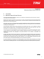
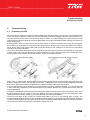
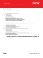
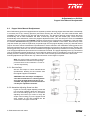
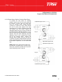
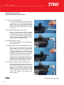
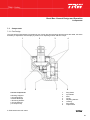
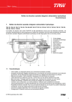
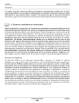
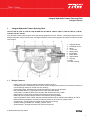
Integral Hydraulic Power Steering Gear
Design Features
1.
Integral Hydraulic Power Steering Gear
TAS 30, TAS 55, TAS 75, TAS 85, TAS 86 AND TAS 87 THP-35, THP-60, THP-70, THP-80, THP-81, THP-82,
THP-90, THP-91, THP-92
The TAS/THP series steering gears were specifically designed for motor vehicles, new design features and our
design experience with previous series of integral hydraulic power steering gears have been combined into this
new product.
1
2
3
4
5
6
1. Adjusting Screw
2. Unloading Valves
3. Worm
4. Torsion Bar
5. Rotary Valve
6. Input Shaft
7. Piston Rack
8. Output Shaft
9. Housing
10. Balls
11. Valve Housing
7
1.1
8
9
10
11
Design Features
-
Rotary Valve. This device provides responsive steering control.
Unloading Valves. Automatically set to furnish power steering pump protection and reduce pressure to
unload steering linkage at vehicle axle stop settings.
Recirculating balls. Combine high mechanical efficiency with smooth operation.
Dirt and Water Seals. Lip type seals on both input and output shafts
Torsion Bar. Provides positive valve centering with definite "feel of the road".
Relief Valves. Furnish pump protection by limiting maximum pressure.
Balanced Area Cylinder. Back pressures cannot affect steering stability.
High Temperature Seals. These specially developed seals may be operated intermittently at 120º C.
Manual Steering Capability. Provides for steering control in the event of hydraulic failure.
Compactness. Lowest weight-to-Output torque ratio in the industry.
Auxiliary Porting Available. For auxiliary cylinder control
Seal Protectors. Provide protection from harsh environment
© TRW Automotive INC. 2009
TRW
1
Integral Hydraulic Power Steering Gear
Definitions
1.2
Definitions
NOTE:
A NOTE gives key information to make a procedure easier or quicker to follow.
CAUTION:
A CAUTION refers to those procedures that must be followed to avoid damage to a steering
component or the gear.
WARNING:
A WARNING REFERS TO THOSE PROCEDURES THAT MUST BE FOLLOWED FOR THE
SAFETY OF THE DRIVER AND THE PERSON INSPECTING OR REPAIRING THE GEAR.
1.3
Disclaimer
This Maintenance Manual has been prepared by TRW AESL for reference and use by mechanics who have been
trained to service steering components and systems on heavy commercial vehicles. TRW AESL has exercised
reasonable care and diligence to present accurate, clear and complete information and instructions regarding the
techniques and tools required for maintaining, repairing and servicing the complete line of TRW TAS and THP
Series Integral Power Steering Gears. However, despite the care and effort taken in preparing this general
Maintenance Manual, TRW makes no warranties that (a) the Maintenance Manual or any explanations illustration,
information, techniques or tools described herein are either accurate, complete or correct as applied to a specific
TAS and THP steering gear, or (b) any repair or service of a particular TAS / THP steering gear will result in a
properly functioning steering gear.
If inspection or testing reveals evidence of wear or damage to the TAS/THP steering gear or you encounter
circumstances not covered in the Manual, STOP - CONSULT THE VEHICLE MANUFACTURERS SERVICE
MANUAL AND WARRANTY.
It is the responsibility of the mechanic performing the maintenance or service on a particular TAS / THP steering
gear to (a) inspect the steering gear for abnormal wear and damage, (b) choose a work procedure which will not
endanger his/her safety, the safety of others, the vehicle, or the safe operation of the vehicle, and (c) fully inspect
and test the TAS steering gear and the vehicle steering system to ensure that the service of the steering gear has
been properly performed and that the steering gear and system will function properly.
1.4
Patents
TRW AESL TAS / THP Power Steering Gear are covered by several Spanish and foreign patents either issued
or pending.
TRW
2
© TRW Automotive INC. 2009
Introduction
Maintenance Manual TAS and THP series
2.
Introduction
2.1
Maintenance Manual TAS and THP series
This service manual has one purpose: to guide you in maintaining, troubleshooting and servicing the TAS and
THP Integral Power Steering Gears.
Material in this manual is organised so you can work on a TAS / THP series steering gear and get results without
wasting time or being confused. To get these results, you should review the contents of this manual before you
begin any work on the steering system.
The section of this manual on General Design and operation addresses the major components of the steering gear
and explains how they function together. The knowledge you acquire from reviewing this section should assist you
in solving your steering problem.
This manual also contains trouble shooting information and checklists. With them, you can diagnose a steering
problem without removing the TAS / THP steering gear from the vehicle. If you must service the TAS / THP
steering gear, the checklists will help you to determine where the problem may be.
The three-column format of the Adjustments section will make it easier for you to service the steering gear. Column
1 gives a brief key for each procedure. Column 2 explains in detail the procedure you should follow. Column 3
illustrates this procedure with photographs. Pay special attention to the “NOTES", "CAUTIONS" and
"WARNINGS".
A foldout page (page 23) with the same typical TAS / THP steering gear exploded assembly view on both sides is
provided in this manual. The component part names and item numbers assigned on this exploded assembly view
correspond with names and item numbers (in parentheses) used in the adjusting procedures set forth in this
manual. When this exploded assembly view page is folded out, you can easily identify components and locate
their relative position on the exploded assembly view as you follow the procedures.
As you gain experience in servicing the TAS steering gears you may find that some information in this manual
could be clearer and more complete. If so, Jet us know about it. Don't try to second guess the manual; if you are
stuck, contact us. Maintaining the TAS / THP series steering gears should be a safe and productive procedure.
© TRW Automotive INC. 2009
TRW
3
TAS / THP Oil Flow Illustration
Maintenance Manual TAS and THP series
3.
TAS / THP Oil Flow Illustration
Neutral (No Steering Action)
Right Hand Turn
Steering Wheel Input
Clockwise Rotation
Left Hand Turn
Steering Wheel Input
Counter -Clockwise Rotation
Supply Pressure
Return Pressure
TRW
4
© TRW Automotive INC. 2009
TAS / THP General Design and Operation
Design
4.
TAS / THP General Design and Operation
4.1
Design
4.1.1 Integral Power Steering
The THP power steering gear series are the latest design in the family of integral hydraulic power steering gears.
Integral hydraulic power steering means that the gear box contains a manual steering mechanism, a hydraulic
control valve, and a hydraulic power cylinder, all in a single, compact package.
4.1.2 Rotary Control Valve
The rotary control valve combines simplicity of construction with desirable performance characteristics. The speed
at which the driver can turn the steering wheel with power assist is dependent upon the pump flow (measured in
litres per minute/lpm) directed to a cylinder cavity. The pressure (measured in bar) required for the gear to steer the
vehicle is created by the power steering pump to overcome resistance at the steered wheels.
The control valve senses these requirements and directs fluid to the appropriate cylinder cavity in the steering gear
and in the auxiliary cylinder if it is a dual steering system at the proper flow rate and pressure.
4.1.3 Pressure Means Work, Flow Means Speed
The TAS / THP series gears can steer a vehicle within its front-end weight rating through a turn at low speed and
engine idle. As the driver turns the steering wheel faster or slower, more or less fluid will be required by the gears.
The higher pressure a steering gear can withstand, the more work it can perform. TAS and THP series might work
up to a maximum operating pressure of 185 bar and to a maximum flow rate of 26.5 Ipm. depending on the model.
4.2
Operation
4.2.1 What Happens During a Steering Manoeuver.
When the driver turns the steering wheel, he transmits force from the steering wheel to the steering gear input
shaft. A torsion bar, pinned at its one end to the input shaft and at its other end to the worm shaft, turns with the
input shaft and exerts a rotational force on the worm shaft. In response to this rotational force, the worm shaft,
acting through the recirculating ball mechanism, tries to move the rack piston axially through the gear housing
cylinder bore.
The rack piston's axial movement is resisted by its engagement to the sector shaft which is connected by linkage
to the steered wheels. Because of this resistance, the torsion bar is twisted by the input shaft, thereby actuating
the control valve. Pressurised fluid, directed by the control valve, assists in moving the rack piston axially through
the cylinder bore: The rack piston then turns the sector shaft to steer the vehicle.
4.2.2 Shock Loads to the Gear
If the steered wheels receive a shock load, the shock forces are transmitted through the sector shaft to the rack
piston, and onto the worm shaft. The internal geometry of the steering gear causes the control valve to send highpressure fluid to the correct cylinder cavity to resist the shock forces. By absorbing the shock forces hydraulically,
the steering gear prevents objectionable kickback at the steering wheel.
© TRW Automotive INC. 2009
TRW
5
TAS / THP General Design and Operation
Operation
4.2.3 Unloading (Poppet) Valves
TAS / THP gears are equipped with two unloading valves, one at each end of the rack piston. One valve or the
other depending on the direction of turn, will trip as the steered wheels approach the axle stops (which must be set
according to manufacturer's specification). The tripped valve reduces pressure in the gear and helps to reduce
heat generated by the pump. At the same time, the valves also reduce forces on the steering linkage. These valves
are automatically set to axle stops after installation in vehicle at first full-right and left turn.
4.2.4 Relief Valve
TAS / THP gears are supplied with a relief valve. The relief valve limits maximum supply pressure to protect the
power steering system and linkages, but it does not reduce pressure as the steered wheels approach the axle
stops.
4.2.5 Bleed Systems
Some TAS / THP gears which are mounted with the output shaft above the rack piston bore are equipped with
either an automatic bleed system or a manual bleed screw.
The procedure for servicing or using the manual bleed screw is described under "Filling and Air Bleeding" in this
manual. If the unit has an automatic bleed system, no servicing is required on the vehicle.
4.2.6 Dual circuit valve
To pass the 92/62/CEE directives for emergency steering TAS-85, THP-80 and THP-90 models can be equipped
with a dual circuit valve. Two versions are available. TAS-86, THP-81 and THP-91 for a single steered axle vehicle.
TAS 87, THP-82 and THP-92 for a twin steered vehicle with auxiliary cylinder.
TRW
6
© TRW Automotive INC. 2009
TAS / THP General Design and Operation
TAS-86, THP-81 and THP-91 Dual Circuit Valve Working Principle
4.3
TAS-86, THP-81 and THP-91 Dual Circuit Valve Working Principle
With the vehicle stationary and the engine off; the spring shown on the right side of the valve schematic will
position the spool to complete the hydraulic circuit shown. In this position the wheel driven pump, item number 2,
is connected to the steering gear, item number 4. When the engine is started, the primary pump, item number 1,
begins to send fluid to the valve, the fluid passes through the check valve (8), the fixed orifice, and the steering
gear. As the fluid passes through the fixed orifice, a pressure differential is created. The higher pressure is
communicated to the left and the lower pressure is communicated to the right side of the spool. As the flow
increases, so does the differential pressure. When the force created by the differential pressure exceeds the
spring force, the spool moves to the position shown on the left side of the valve schematic. This is the normal
operating position. The variable orifice shown in the diagram is an area formed between the edges of the spool
and housing that enlarges to the extent that flow exceeds that needed to shift the spool. When a failure occurs to
this normal operating circuit, the fluid flow delivered to the fixed and variable orifice will diminish to a level where
fluid will cease to flow through the variable orifice and the fluid flow past the fixed orifice will not be enough to hold
the spool shifted against the spring force. At this time the spool will shift and all the flow from the road wheel driven
pump (2) will be directed to the steering gear (4) and added to that being delivered by the engine driven pump (1)
that is below the minimum threshold requirement. If the fluid flow from the engine driven pump (1) fails due to a
rupture hose, for example, the check valve (8) would prevent the wheel driven pump from being lost through the
rupture and all the flow being delivered to the steering gear would be from the wheel driven pump (2).
Dual Circuit Double Spool Valve Hydraulics Scheme - Straight Line Position - Working Situation
1 - Main Pump
2 - Emergency Pump after gear box
(only turns when the vehicle moves)
3 - Reservoirs + filters
4 - Steering Gear
5 - Steering Gear Valve
6 - Dual Circuit Slide Valve
7 - Pressure Relief Valve
8 - Check Valve ( inside P 1 racord )
Dual Circuit Steering System that automatically switches from the primary (Engine Driven Pump) to the
secondary (Road Wheel Driven Pump) fluid power source upon failure of the primary source to deliver fluid flow.
© TRW Automotive INC. 2009
TRW
7
TAS / THP General Design and Operation
TAS-87, THP-82 and THP-92 Dualcircuit Valve for Two Steered Axle Trucks
4.4
TAS-87, THP-82 and THP-92 Dualcircuit Valve for Two Steered Axle Trucks
The primary difference between this system and the single axle one is the addition of another spool type manifold
valve (7) that is actuated by the same pressure differential as the first valve. When the P1 pump (1) fails to deliver
enough flow to hold the first valve spool (6) over against the spring load, the first spool (6) shifts and the pressure
differential between either end of the spool drops rapidly. Since the second valve spool is held in the operating
position due to this pressure differential, when the differential is lost, the spool shifts. In this shifted position the
power to steer the second axle (9) is no longer available, but the remaining power available should be satisfactory
to meet the 92/62/CEE performance specifications.
1 - Main Pump
2 - Emergency Pump after gear box
(only turns when the vehicle moves)
3 - Reservoirs + filters
4 - Steering Gear
5 - Steering Gear Valve
6 - Dual Circuit First Slide Valve
7 - Dual Circuit Second Slide Valve
8 - Pressure Relief Valve
9 - Auxiliary Cylinder for 2nd Steered
Dual Circuit Steering System that automatical switches from the primary (Engine Driven Pump) to the secondary
(Road Wheel Driven Pump) fluid power source upon failure of the primary source to deliver fluid flow.
It also by-passes the action of the cylinder upon same failure.
TRW
8
© TRW Automotive INC. 2009
Troubleshooting
Preliminary Checks
5.
Troubleshooting
5.1
Preliminary Checks
When a customer comes to you with a problem related to his vehicles steering, you can save a lot of time and work
if you first verify the problem. Make sure you are both talking the same language about the same problem. If he
says the vehicle's hard to steer, find out exactly what he means. Is it hard steering into a right or left turn? Only
when turning the steering while the vehicle is sitting still? Is there only intermittent power steering? Or is there no
power assist at all?
If at all possible, and if it is safe to do so, test drive the vehicle. If you are not familiar with the rig, jet the customer
drive it while you sit beside him. Take hold of the wheel while he drives to get a feel for the problem he is talking
about. Since most of his driving will be with his vehicle hauling a load, arrange for a load if one is required to
reproduce the steering problem.
Once you've determined the problem and its symptoms, don't jump right in to tear the steering gear or pump apart.
In most cases, in fact, the gear should be the last component you check. There are many other components in the
steering system that could be causing the problem. These you should check first.
Typical Steering System
Typical Steering System (with Auxiliary Cylinder)
Begin, then, by checking the steered wheels: make sure that the tires are at correct pressure and equal all around,
that they are properly sized, and that they are not worn or damaged. Next, have the frontend alignment checked
and look for abnormal looseness or tightness in the steering linkage, ball joints, and kingpins.
A service replacement hose or fluid line may be misrouted or may be to a small in diameter, or it may be restricted
in some other way. Replace any hose that is kinked or bent sharply. Replace any hoses that are not the same as
original equipment.
Continue by checking the power steering fluid reservoir to make sure that oil is up to the correct level. Also, check
the pump drive belt, if one is used, to see if it is slipping. The belt may be tight, but it may also be glazed, and a
slipping belt doesn't always squeal. If you adjust the belt, check the specifications.
These are just some of the checks you should make before you turn to the steering gear or pump. The
Troubleshooting Guide on pages 12 thru 14 explains what to diagnose for a particular steering problem. Match the
trouble symptom against the chart and follow the recommended troubleshooting sequence. Doing so will most
likely save you time and may prevent unnecessary repairs and costs.
© TRW Automotive INC. 2009
TRW
9
Troubleshooting
Hydraulic Tests
5.2
Hydraulic Tests
Thermometer
If the checks described above all prove satisfactory, it is
possible that the cause of the steering problem can be
traced to a lack of pressure or insufficient flow. In this
case, you may have to do more detailed troubleshooting
that involves conducting hydraulic tests.
Reservoire
Filter
5.2.1 Preparation for Hydraulic Tests
To conduct the following hydraulic tests, first install a flow
meter, pressure gauge and load (shut off) valve in the
fluid supply line to the steering gears, as indicated by the
instructions that come with the flow meter. Place a
thermometer in the reservoir (Fig.2). You must use a flow
meter, and it is recommended that you use a
thermometer, if you are to troubleshoot the hydraulic
system accurately. Start the engine and warm the
hydraulic system up by partially closing the load valve
until the pressure gauge reads 70 Bar. When the fluid
temperature .as indicated on the thermometer, reaches
between 50ºC and 60ºC open the load valve. The system
is warmed up. And you can conduct the tests.
Pressure Gauge
Load (Shutoff) Valve
Power Steering Pump
Steering Gear
Fig.2
CAUTION: Do not close the load valve completely and leave it closed, or you may damage the
pump. At no time allow fluid temperature to exceed 80°C. Run all the tests at the prescribed temperature range of 50°C and 60°C.
5.2.2 Power Steering Pump Pressure Test
With the engine idling, close the load valve and read the pressure gauge. If the pressure reads below the minimum
specified by the pump manufacturer, repair or replace the pump.
CAUTION: Do not keep the load valve closed for longer than 5-10 seconds to avoid damaging the
pump. Closing the load valve causes the pump to operate at relief pressure and the fluid temperature to increase rapidly. Allow fluid to cool to between 50°C and 60°C before you resume with
the other tests.
5.2.3 POWER STEERING PUMP FLOW TEST
WARNING: DO NOT EXCEED THE MAXIMUM FLOW AND PRESSURE RATE SPECIFIED BY THE
VEHICLE MANUFACTURER. EXCESSIVE FLOW OR PRESSURE CAN CAUSE DAMAGE TO INTERNAL PARTS OF THE STEERING GEAR, WHICH COULD RESULT IN A LOSS OF POWER
STEERING.
NOTE: If flow specifications and methods of checking flow rate are provided by the vehicle manufacturer,
you should follow those instructions rather than the procedure described below.
TRW
10
© TRW Automotive INC. 2009
Troubleshooting
Hydraulic Tests
With the engine idling and the fluid temperature between 50°C and 60°C check the pump manufacturer's
specifications for flow rate. Compare these specifications with the flow rate on the flow meter. Now, fully close the
load valve until the pressure gauge registers the maximum working pressure of the steering gear.
INMEDIATELY OPEN THE LOAD VALVE. The flow rate must instantly return to the original reading. If this rate
does not return immediately, the pump is malfunctioning, which can result in intermittent power assist.
NOTE: Conduct the pump flow test once at idle rpm and once more at three times the idle rpm.
CAUTION: Do not allow the fluid temperature to exceed 80°C.
Run each phase of this test between 50°C and 60°C.
5.2.4 STEERING GEAR INTERNAL LEAKAGE TEST
To test the steering gear for internal leakage, you must first
prevent operation of the gears internal unloading (poppet)
valves or relief valve (or both, in some gears). This will allow
full pump relief pressure to develop. To prevent operation of
the poppets, place an unhardened steel spacer block, about
25mm thick and long enough to keep your fingers clear,
between the axle and stop at one wheel (see Fig.3).
To prevent operation of the relief valve, remove the relief
valve and install the relief valve plug, special tool SK12986
in its place (Consult TRW).
Axle Stop
Fig.3
NOTE: Be sure you reinstall the relief valve and
valve cap with new o-ring, back onto the gear after
leakage test.
With the fluid temperature between 50°C and 60°C turn the steering wheel until the axle stops bottom on the
spacer block (FIG.3).
CAUTION: When running this test, do not hold the steering wheel in the full turn position for longer than 5 to 10 seconds at a time to avoid damaging the pump
WARNING: KEEP YOUR FINGERS CLEAR OF THE AXLE STOPS AND SPACER BLOCK DURING
THIS TEST. MAKE SURE THAT THE SPACER BLOCK CONTACTS THE AXLE STOP SQUARELV.
A CONTACT THAT IS NOT SQUARE COULD BREAK THE AXLE STOPS OR DANGEROUSLY
THROW OR EJECT THE SPACER BLOCK.
Apply 100 N to the rim of the steering wheel during this test to ensure that the steering gear control valve is fully
closed. The pressure gauge should now read the maximum pump pressure, as noted during the pump pressure
test. You can now read steering gear internal leakage on the flow meter. Repeat this test for the opposite direction
of turn. Acceptable internal leakages of the hydraulic system can range from 0 to 5.7 litre/min.
If internal leakage is greater than 3.8 Litre/min depending on the model and maximum working pressure and there
is no auxiliary hydraulic cylinder in the system, repair the gear.
© TRW Automotive INC. 2009
TRW
11
Troubleshooting
Troubleshooting Guide
If the internal leakage is greater than 5.7 Litre/min and there is an auxiliary hydraulic cylinder in the system,
controlled by the TAS/THP gear, isolate the auxiliary cylinder from the system by disconnecting the auxiliary
cylinder lines at the TAS/THP units auxiliary ports. Plug those ports with suitable pressure plugs or caps. Connect
the disconnected lines together if a rotary auxiliary cylinder is in the system. Plug the disconnected lines if a linear
auxiliary cylinder is in the system and disconnect the linear cylinder from the steering linkage making sure it will
clear the steered axle.
Repeat the internal leakage test. If the internal leakage is less than 3.8 Litre/min repair the auxiliary cylinder. If the
internal leakage is greater than 3.8 Litre/min, repair the TAS / THP gear.
NOTE: When hydraulic tests are completed and fluid lines are reconnected, check fluid level and air
bleed the system.
5.3
Troubleshooting Guide
5.3.1 Normal Noises I
-
You or the driver may hear a hissing noise from the control valve when it is actuated during a
steerin manoeuvre
You or the driver may hear a noise as fluid bypasses through the poppets at full turn.
You or the driver may hear a noise from the system relief valve when it is required to actuate.
You or the driver may hear pump growl from some types of power steering pumps.
5.3.2 Abnormal Noises
-
If the power steering pump is belt driven, a squealing noise may indicate that the belts should be tightened
or replaced.
A clicking noise heard during a turn, or when changing directions, may indicate that some component is
loose and shifting under load.
A change in the normal noise of the pump may indicate that air has been induced into the system or that
fluid level is low.
5.3.3 Possible Steering Problems and Causes
5.3.3.1
-
Road Wander
Tire pressure incorrect or unequal left to right.
Components in steering linkage loose or worn (Steering wheel to road wheel)
Wheel bearings improperly adjusted or worn.
Front end alignment out of specification.
Dry fifth wheel or poor finish on fifth wheel or trailer plate.
Steering gear mounting bolts loose on frame.
Steering gear improperly adjusted.
Looseness in rear axle assemblies or trailer bogies.
TRW
12
© TRW Automotive INC. 2009
Troubleshooting
Troubleshooting Guide
5.3.3.2
-
Tire pressure low
Front end components binding
Tight front axle kingpins
Dry fifth wheel or poor finish on fifth wheel or trailer plate
Steering column binding
Pump flow insufficient
Steering gear improperly adjusted
Steering gear control valve sticking
Front end alignment incorrect
5.3.3.3
-
-
Oversteering or Darting
Dry fifth wheel or poor finish on fifth wheel or trailer plate
Front end components binding or loose
Steering column binding
Steering gear improperly adjusted
Steering gear control valve sticking
Rear axle mounts (rear steer)
5.3.3.6
-
External Oil Leakage
Finding the location of a leak mar be difficult, since oil mar run away from the leak source, the fittings, hoses,
pump or gear to a low point on the gear or chassis.
A leak from the vent plug at the side cover indicates failure of the sector shaft oil seal inside the side cover.
5.3.3.5
-
Shimmy
Badly worn or unevenly worn tires
Improperly mounted tire or wheel
Wheel bearings improperly adjusted or worn
Components in steering linkage loose or worn
Wheels or brake drums out of balance
Front end alignment incorrect
Air in the hydraulic system
5.3.3.4
-
No Recovery
High Steering Effort in One Direction
Unequal tire pressure
Vehicle overloaded
Inadequate hydraulic system pressure
Excessive internal leakage in one direction of turn only (verify with internal leakage test)
© TRW Automotive INC. 2009
TRW
13
Troubleshooting
Troubleshooting Guide
5.3.3.7
-
Low tire pressure
Vehicle overloaded
Low hydraulic fluid level
Low pressure or flow from pump
Components of steering system binding
Restriction in return line, or line to a small in diameter
Excessive internal leakage (verify with internal leakage test)
Oversize tires (check manufacturer's specifications)
5.3.3.8
-
Lost Motion (Lash) at the Steering Wheel
Steering wheel loose on the shaft
Loose connection between the steering gear, intermediate column, and steering column.
Steering gear loose on frame
Pitman arm loose on output shaft .
Components in steering linkage loose or worn
Steering gear improperly adjusted
5.3.3.9
-
High Steering Effort in both Directions
Excessive Heal Oil temperature not to exceed 120°C Continuously
Excessive pump flow
Vehicle overloaded
Undersized replacement hose or line
Restricted hose or line that is kinked or severely bent or internally blocked
Restricted re-entering of gear valve caused by column bind or side load on the input shaft
Poppet not functioning properly
Prolonged stationary vehicle operation
WARNING: IF THE HYDRAULIC SVSTEM FLUID BECOMES OVERHEATED, IT CAN CAUSE THE
SEALS IN THE STEERING GEAR AND PUMP TO SHRINK, HARDEN, OR CRACK AND LOSE THEIR
SEALING ABILITY
TRW
14
© TRW Automotive INC. 2009
Adjustments on Vehicle
Sector-Shaft Adjustment
6.
Adjustments on Vehicle
NOTE: All Numbers in the brackets refer to chapter 6.4 page 23. When you have conducted the checks and
tests described in the troubleshooting sections, you may find it necessary to adjust the steering gear. There are
two adjustments to be made to the steering gear while it is installed on a vehicle. One is the sector shaft
adjustment, and only if the shaft adjusting screw and jam nut (45) are accessible. A manual poppet adjustment is
possible after initial poppet valve adjustment at installation. If the steering gear has a fixed stop screw (38) and
washer (39), you must replace them with a special service poppet adjusting screw (41) and sealing nut (40) to
make this adjustment. Some of the photographs in this section show a gear mounted on a mock-up frame for clear
illustration.
Worm preload was achieved during assembly of the steering gear. If axial lash (movement) of input shaft is
evident during a steering manoeuvre, the steering gear must be disassembled and repaired.
6.1
Sector-Shaft Adjustment
6.1.1 Locate adjusting nut
(With vehicle engine off) If the sector-shaft
adjusting screw jam nut (45), located on the
side cover, is not accessible, the steering gear
must be removed prior to adjustment.
Timimg Marks
6.1.2 Centre the sector shaft
To position the sector shaft (42) on centre of
travel for this adjustment, rotate steering wheel
(input shaft, valve worm assembly) until the
timing mark across the end of the sector shaft
is perpendicular to the input shaft, valve worm
assembly and in line timing mark on the end of
housing (31) trunnion (Fig.4).
Fig.4
CAUTION: This adjustment must be performed with the sector shaft on its centre of travel..
6.1.3 Remove the drag link
If the sector shaft adjusting screw is accessible
for adjustment, remove the drag link from the
pitman arm (Fig.5).
CAUTION: The input shaft, valve worm assembly (14), must not be rotated more then
1-1/4 revolutions from the centre of travel
while the drag link is detached from steering gear to avoid possible maladjustment of
the poppet system.
© TRW Automotive INC. 2009
Fig.5
TRW
15
Adjustments on Vehicle
Sector-Shaft Adjustment
6.1.4 Check for lash
With the sector shaft (42) in the centre position, grasp the pitman arm and gently try to move this arm
back and forth in the direction of travel. Fingertip force is adequate to detect lash of loose sector shaft.
There must not be movement of the input shaft or sector shaft (Fig.5).
6.1.5 Position Adjusting Screw
Loosen jam nut (45). If no lash was detected, turn shaft adjusting screw counter clockwise until lash is
detected.
6.1.6 Adjust Shaft
To adjust, slowly turn the shaft adjusting screw
clockwise until no lash is felt at the pitman arm.
(Use no more than 14 Nm of torque). From this
no lash position, turn screw clockwise an
additional 1/8 to 1/4 of a turn. Hold the
adjusting screw in place, and tighten the jam
nut (45). Final torque: as per Torque Chart
(Fig.6).
CAUTION: Overadjustment of shaf adjusting screw clockwise could induce a no recovery, over-steering or darting condition in
the vehicle.
Fig.6
6.1.7 Recheck for lash
Recheck the pitman arm for lash. Turn the steering wheel 1/4 turn each side of centre. No lash should
be felt. If lash exists, repeat step 5 through 7.
6.1.8 Connect drag link
Reconnect drag link to pitman arm
TRW
16
© TRW Automotive INC. 2009
Adjustments on Vehicle
Poppet Valve Manual Readjustment
6.2
Poppet Valve Manual Readjustment
Most TAS steering gears are equipped with two hydraulic pressure relieving poppet valves that were automatically
or manually set to trip, relieving pressure just before reaching the axle stops. This was achieved after initial
installation into the vehicle at the first full right and left turn. The pressure relieving poppet valves that were
automatically set at initial installation will have a fixed stop screw (38) and washer (39). These units will
automatically reset themselves, within the poppets adjustment limits, if the axle stops are reset for increased
steering gear travel based on acceptable equipment revisions from original factory installations. If the axle stops
are reset for decreased steering gear travel with the steering gear installed on the vehicle, the fixed stop screw
(38) and washer (39) must be replaced by a special length service poppet adjusting screw (41) and seal locknut
(40) kit. Check the vehicle manufacturers specifications or service manual or the TRW AESL steering gear service
parts list to determine the correct replacement poppet adjusting screw and nut kit required for the specific TAS
steering gear being serviced. The vehicle manufacturer's poppet adjustment procedures must take precedence
over the poppet adjustment procedures in this maintenance manual. The poppet adjusting screw (41) and locknut
(40) are supplied as original equipment on some TAS/THP steering gears. If the adjusting screw and locknut are
already part of the steering gear assembly, remove the screw from the gear and measure the total screw.
Following adjustment procedures are only valid when 55mm screw length is required.
Note: If a longer screw is used (65 or 75 mm)
all the dimensions indicated in this adjusting
procedure have to be increased in +10 mm or
+20 mm respectively.
6.2.1 Set Axle Stop
Set the axle stops to vehicle manufacturer's
specifications, allowing for the revisions from
the original equipment installation.
CAUTION: If the axle stops are adjusted
such that a minimum of 1.4 steering wheel
turns from straight ahead position is not
available, the poppets are not functional nor
can they be adjusted to function.
Fig. 7A
6.2.2 Assemble Adjusting Screw into Nut
Figure 7A If a new poppet adjusting screw and
nut are being installed, adjust the locknut on
the screw according figure 7A or 7B. Before
adjusting the locknut you need to verify the
shape of the housing (31) in the poppet screw
area, present on the gear installed into the
vehicle. See also figure 7A and 7B.
© TRW Automotive INC. 2009
Fig. 7B
TRW
17
Adjustments on Vehicle
Poppet Valve Manual Readjustment
6.2.3 Remove Poppet Stop Screw
With the vehicle unloaded, the engine off and
the road wheels in "straight ahead position",
remove and discard the poppet fixed stop
screw (38) and washer (39) from the lower end
of housing (31) if the unit is so equipped (Fig.8)
If the unit has a poppet adjusting screw (41)
and nut (40), and they are to be replaced,
remove and discard them at this time.
Fig.8
NOTE: With the road wheels in the "straight
ahead position", the steering gear is in its centre position only when timing marks on the end
of the sector shaft and housing trunnion are
aligned.
6.2.4 Turn Adjusting Screw Assembly into Housing
Fig.9
Adjust the locknut on the screw according step
2 of this procedure as described before. Turn
the new adjusting screw (41) and locknut (40)
assembly, without rotating the nut on the
screw, into the housing until the nut is firmly
against the housing (Fig.9). Final torque the
nut to 20-30 Nm (Fig.10).
NOTE: It may be necessary to move the sector
shaft slightly from the "straight ahead position"
to assemble the service adjusting screw as instructed and then return into „straight ahead“.
6.2.5 Refill Pump Reservoire
Refill pump reservoir with approved hydraulic
fluid.
Fig.10
NOTE: If excessive input shaft torque to apply
in the steering wheel is encountered prior to
reaching the axle stop, allow vehicle to roll
slowly forward while rotating steering wheel or
jack up the vehicle at the front axle.
TRW
18
© TRW Automotive INC. 2009
Adjustments on Vehicle
Poppet Valve Manual Readjustment
6.2.6 Rotate Sector Shaft to Position Rack Piston
To position the rack piston for resetting
poppets, observe the end of sector shaft (42)
for direction of travel. With the engine idle,
have the steering wheel rotated direction
necessary to rotate the sector shaft towards
the end of travel (axle against axle stop)
clockwise (cw) or counter clockwise (ccw) that
will position the rack piston toward the
adjustable poppet screw (41) at the closed end
of housing (31) by referring to figures 11 & 12.
When the initial internal engagement of poppet
adjuster seat and sleeve assembly (22) and
adjusting screw is felt, evidenced by torque
rise at the steering wheel, continue the
steering wheel rotation until the axle stop is
contacted. The upper poppet adjuster seat and
sleeve assembly (22) is now pre-set internally
for automatic adjustment to the related axle
stop.
Adjustable Poppet Screw
Fig.11
Adjustable Poppet Screw
Adjustable Poppet Screw
NOTE: Make note of the steering wheel rotation direction, clockwise (cw) or counter clockwise (ccw), required to position the rack piston
toward adjusting screw in step #6.
Fig.12
Adjustable Poppet Screw
© TRW Automotive INC. 2009
TRW
19
Adjustments on Vehicle
Poppet Valve Manual Readjustment
6.2.7 Back out Adjusting Screw
Loosen nut (40) and back out adjusting screw
(41) an extra 15-17 mm (dimension as found in
6.2.2 + 15 to 17 mm - Fig.13). Torque nut firmly
against housing while maintaining the screw
protrusion dimension. Final torque nut to 20-30
Nm (Fig.14).
6.2.8 Position upper Poppet to Axle Stop
With the engine at idle and the vehicle
unloaded, turn steering wheel toward full travel
in the opposite direction used and noted in
step 6.2.6 until axle bottoms against the axle
stop. This will automatically position the upper
poppet valve to the related axle stop.
Fig.13
6.2.9 Install Pressure Gauge
Install a pressure gauge in the fluid supply line
to the steering gear.
6.2.10Position Rack Piston toward Adjusting Screw
Fig.14
With the engine at idle, have the steering
wheel rotated in the direction determined and
noted in step 6.2.6 until the axle stop is
contacted, positioning the rack piston toward
the poppet adjusting screw (41) at closed end
of housing (31). At this point, the system will be
operating at system (pump) relief pressure.
CAUTION: At no time should relief pressure
be maintained for longer than 5 seconds, as
damage to the steering pump may result.
Fig.15
6.2.11Position Adjusting Screw and Torque Nut
With the steering wheel being held in this axle
stop contact position, loosen the nut (40) one
turn and turn the adjusting screw (41) in while
holding the nut (Fig.15). Continue turning
adjusting screw until a pressure drop is seen
on the pressure gauge. Final torque nut: See
Torque Chart (Fig.16). and disconnect the
pressure gauge.
Fig.16
TRW
20
© TRW Automotive INC. 2009
Adjustments on Vehicle
Poppet Valve Manual Readjustment
WARNING: THE MAXIMUM ADJUSTING SCREW PROTRUSION FROM SEALING NUT AS GIVEN
IN STEP 6.2.7 MUST NOT BE EXCEEDED TO INSURE ADQUATE SCREW THREAD ENGAGEMENT
IN HOUSING. INADEQUATE SCREW ENGAGEMENT COULD CAUSE LOSS OF THE ADJUSTING
SCREW DURING OPERATION WITH RESULTANT LOSS OF POWER STEERING.
The manual poppet valve readjustment is now completed.
CAUTION: Once an adjustable poppet screw and nut are in place and the manual readjustment
procedures have been use d, the procedures must be repeated completely for additional adjustments for either increased or decreased gear travel at either axle stop to ensure that both poppets relieve pressure as required.
NOTE: Properly functioning poppet valves will also facilitate the bleeding of trapped air from the steering
gear.
© TRW Automotive INC. 2009
TRW
21
Adjustments on Vehicle
Torque Chart
6.3
Torque Chart
Universal Joint Bolt: Torque to vehicle manufacturer's specification.
Torque values shown in the chart will be applied to general applications, different torques
calculated by TRW for special applications are shown on „customer drawings“.
TRW
22
© TRW Automotive INC. 2009
1.
2.
3.
4.
5.
5A.
5B.
6.
7.
8.
9.
10.
11.
12.
13.
14.
15.
16.
17.
18.
19.
20.
21.
22.
23.
24.
25.
26.
27.
28.
29.
30.
Bolt
Dirt and Water Seal (Input)
Retaining Ring
Seal (Input Shaft
Valve Housing Assy
Valve Housing Assy (Bevel Box)
Valve Housing Assy (Double Circuit)
„O“ Ring (2)
Port Plugs (2)
Seal Ring
„O“ Ring
Seal Ring
„O“ RingBall
Ball Bearing Race
Ball Bearing Assy
Input Shaft and Valve Worm Assy
Roller Thrust Bearing
Thrust Washer
Bearing Adjuster
Adjuster Locknut
Rack Piston
Seal Ring
„O“ Ring
Poppet Adjuster Seat and Sleeve Assy
Poppet
Poppet Spring
Spacer Rod
Push Tube
Ball
Ball Return guide Halves
Ball Return guide Clip
Torx Screws (2)
31.
32.
33.
34.
35.
36.
37.
38.
39.
40.
41.
42.
43.
44.
45.
46.
47.
48.
Housing
Retaining Ring
Roller Bearing
Dirt Seal
Dirt and Water Seal
Washer (Spacer)
Seal (Output Shaft)
Poppet Fixed Stop Screw
Washer
Seal Lock Nut
Poppet Adjuster Screw
Sector Shaft
Washer
Side Cover
Jam Nut
Side Cover Screw
Vent Plug
Gaiter
49.
50.
51.
52.
53.
54.
55.
56.
57.
58.
59.
60.
61.
62.
63.
64.
65.
66.
67.
68.
69.
70.
71.
72.
Nut
Relief Valve (2Pieces)
„O“ Ring
Relief Valve Cap
„O“ Ring
Coupling
Plug
Washer
Bevel Box
Dirt and Water Seal
Bolt (2)
Double Circuit Valve
Bolt (2)
Anti Return Valve
Bleeder Screw
Cap
Bleeder Pipe Bevel Box (Version)
Oil Plug (2)
Seal Ring (2)
Plug (2)
Automatic Bleeder
Bleeder Seat
Auxiliary Port Plugs (2)
Washer
Adjustments on Vehicle
Exploded View
6.4
Exploded View
© TRW Automotive INC. 2009
TRW
23
Bevel Box: General Design and Operation
Design
7.
Bevel Box: General Design and Operation
7.1
Design
This bevel box design is the most advanced technology of the TRW angular bevel box patents.
The bevel box is a mechanism that permits functions coming from the entrance shaft of a steering gear at an angle
of 90½ to the steering wheel column, thus permitting greater applications in the existing field of vehicles.
The bevel box is a compact package made up of a robust housing and incorporating the input shaft connected to
the steering wheel column, and the output shaft which transmits the movement to the steering gear through the
coupling.
All the mechanism is lubricated for life.
New Design
First Design
7.2
Operation
The input shaft receives the movement that is transmitted from the steering wheel.
Transmission of the movement from the bevel box to the steering gear is made by a coupling of
variable length, depending on the model of the gear.
TRW
24
© TRW Automotive INC. 2009
Bevel Box: General Design and Operation
Components
7.3
Components
7.3.1 First Design
The input shaft is supported by four bearings, two of them are thrust bearings and the others are radial, the whole
assembly is adjusted for zero freeplay by means of an adjusting washer and two circlips.
1
2
5
Current Components
2 Bearing Supports
3 Thrust Bearings
4 Needle Bearings
1 Shimming Washer
2 Thrust Washers
(12 components)
© TRW Automotive INC. 2009
6
3
4
7
8
1.
2.
3.
4.
5.
6.
7.
8.
Ring Guide
Input Shaft
Seal
Circlip
Adjusting Washer
Housing
Ring Guide
Output Shaft
TRW
25
Bevel Box: General Design and Operation
Components
1. Housing
2. Input Shaft Assy
3. Circlip
4. Seal
5. Output Shaft Assy
6. Circlip
7. Coupling
10. Fixing Screw
11. Adjusting washer
TRW
26
© TRW Automotive INC. 2009
Bevel Box: General Design and Operation
Components
7.3.2 New design
The input shaft is supported by two bearings, one of them is ball bearing and the other is a needle bearing, the
whole assembly is adjusted for zero freeplay by means of two circlips.
Ball Bearings
Needle Bearings
New Components
2 Ball Bearings
2 Needle Bearings
(4 components)
© TRW Automotive INC. 2009
TRW
27
Hydraulic Fluid
Components
8.
Hydraulic Fluid
The steering system should be kept filled with one of the following fluids:
•
AUTOMATIC TRANSMISSION FLUID TYPE "E" or "F"
•
AUTOMATIC TRANSMISSION FLUID DEXRON 11
•
CHEVRON TORQUE 5 FLUID
•
CHEVRON CUSTOM 10W40 MOTOR OIL
•
CHEVRON 10W40
•
EXXON NUTO H32 HYDRAULlC FLUID
•
FLEETRIDTE PSF (CAN # 990625 C2)
•
FORD SPEC. M2C138 CJ
•
MACK ED-K2 ENGINE OIL
•
MOBIL ATF 210
•
MOBIL SUPER 10W40 MOTOR OIL
•
SHELL ROTBlA T SAE30
•
SHELL ROTBlA T30W
•
SHELL DONA>< TM
•
SHELL DONA>< TF
•
TEXACO 1QW40
•
TEXACO TL-1833 POWER STEERING FLUID
•
UNjaN 10W40
•
UNION 15W40
•
UNOCAL GUARDOL 15W40 MOTOR OIL
WARNING: COMPLETELY FLUSH THE STEERING SYSTEM WITH ONE OF THE RECOMMENDED
FLUIDS ABOVE ONLY. DO NOT MIX OIL TYPES. ANY MIXTURE OR ANY UNAPPROVED OIL
COULD LEAD TO SEAL DETERIORATION AND LEAKS. A LEAK COULD ULTIMATELY CAUSE
THE LOSS OF FLUID, WHICH COULD RESULT IN A LOSS OF POWER STEERING ASSIST.
TRW
28
© TRW Automotive INC. 2009
Filling and Bleeding
Required Tools and Materials
9.
Filling and Bleeding
9.1
Required Tools and Materials
Caution: For steps 1 and 2, do not turn the steering wheel. Otherwise, air may be induced into
the system!
Make sure poppets are set correctly before beginning this procedure.
1.
Fill the reservoir nearly full. Crank the engine for 10 seconds without allowing it to start, if possible. If the
engine does start, shut it off immediately. Repeat at least three times, each time checking and refilling the
reservoir if needed.
Do not allow the fluid level to drop significantly or run out of the reservoir. This may induce air into the
system.
Run engine for 10 seconds, turn off and fill reservoir
2.
Start the engine and let it idle for 2 minutes. Shut off the engine and check the fluid level in the reservoir.
Refill as required.
Run engine for 2 minutes, turn off and fill reservoir
3.
With the poppets correctly adjusted to relieve pressure at the end of the travel, start the engine again. Steer
the vehicle from full left to full right several times. Add fluid, as necessary, to the full line on the dipstick. The
above procedures should remove all the air from the steering system, unless the gear is mounted in an
inverted position and is equipped with the manual bleed screw (63). Manual bleed systems continue with
step 4.
Steer vehicle
4.
Remove the air from the gear mounted in an inverted position and equipped with a manual bleed screw (63)
by following steps 1, 2, and 3 above. Then, with the engine idling, steer the gear from left turn to right turn
several times. With the steering gear in neutral (no steering action), loosen the manual bleed screw about
one turn, allowing air aerated fluid to ìbleed outî around the bleed screw until only clear (not aerated) fluid
is bleeding out. Then close the bleed screw. Check and refill reservoir. Repeat step 3 to 4 times starting with
the steering manoeuvre with bleed screw closed, until only clear (not aerated) fluid is discharged when
bleed screw is loosened. Torque the manual bleed screw to 5-7 Nm. Check and refill reservoir.
Steer vehicle Allow air to bleed out from bleed screw
CAUTION: Do not turn steering wheel with bleed screw loosened as it could introduce air into the
system.
WARNING: DO NOT LOOSEN OR REMOVE THE POPPET FIXED STOP SCREW(38), AND IF INCLUDED IN THE ASSEMBLY, DO NOT LOOSEN OR REMOVE THE AUTO -B LEED TUBE (65) OR
AUXILIARY PORT PLUGS (71) WHEN THE STEERING GEAR IS MOUNTED ON THE VEHICLE. IF
LOOSENED OR REMOVED, THERE MAY BE A LOSS OF POWER STEERING ASSIST IN ONE DIRECTION OF TURN.
© TRW Automotive INC. 2009
TRW
29
Warnings
Warnings for Proper Steering Gear Operation
10. Warnings
10.1 Warnings for Proper Steering Gear Operation
WARNING: DO NOT WELD, BRAZE OR SOLDER ANY STEERIN GEAR OR SYSTEM ARM COMPONENTS
WARNING: MAXIMUM OPERATING PRESSURE MUST NOT EXCEED THE PRESSURE RELIEF
VALVE SETTING MARKED IN THE INDENTIFICATION LABEL OF THE STEERIN GEAR
WARNING: ALWAYS CAREFULLY INSPECT ANY STEERING COMPONENT WHICH HAS BEEN
(OR IS SUSPECTED TO HAVE BEEN) SUBJECTED TO IMPACT. REPLACE ANY DAMAGED OR
QUESTIONABLE COMPONENT
10.2 WARNINGS FOR PROPER STEERING GEAR APPLICATION
WARNING: GEAR APPLICATION IN THE VEHICLE ACORDING TO TRW STANDARD 31 877 003
WARNING: PERMISSABLE THERMAL LOAD OF THE GEAR ACORDING TO TRW STANDARD 31
877 002
TRW
30
© TRW Automotive INC. 2009
Positioning Automatic Poppets after installing Steering Gear
Position Poppet to Axle Stop
11.
Positioning Automatic Poppets after installing Steering Gear
CAUTION: If the poppet adjuster seat and sleeve assemblies (22), were not set for automatic poppet adjustment after installation. When steering gear was disassembled and the unit has a fixed
stop poppet screw (38) and washer (39), and if the axle stops were adjusted for decreased travel
or if the steering gear is being installed in a different vehicle, it will be necessary to procure the
special service poppet adjusting screw (41) and nut (40). You will then have to follow the "alternate method" of setting the poppets manually. (page 18)
CAUTION: The axle stops and all steering linkage must be in accordance with vehicle manufacturer's specifications. The pitman arm correctly aligned on the steering gear sector shaft or the
poppets may be automatically set incorrectly and require disassembly of the steering gear or a
service adjusting screw procedure to rectify.
11.1 Position Poppet to Axle Stop
This procedure assumes that the steering gear automatic poppet adjuster seat and sleeve assemblies (22) are as
pre-set at the factory or have been reset while disassembled for automatic poppet adjustment alter installation in
the vehicle. It also assumes the fixed stop screw (38) and washer (39) is in the housing or that fixed stop screw
length (standard 30 mm) that protrudes into the housing has been duplicated with the poppet adjusting screw (41)
and nut (40). With the engine at idle and the vehicle unloaded, turn the steering wheel toward full travel in one
direction until the steering gear linkage firmly bottoms against the axle stops. Maximum input torque to be applied
during this procedure is 55 Nm or 220 N rim pull on a 500 mm diameter steering wheel. This will automatically
position the poppet adjuster seat and sleeve assembly in relation to the axle stop.
NOTE: If excess input shaft torque or rim pull is encountered prior to reaching the axle stop, allow vehicle
to roll forward or jack up the vehicle at the front axle.
11.2 Position other Poppe
Follow the same procedure while turning the steering wheel in the other direction. The poppet valves are now
positioned to trip and reduce pressure as the steered wheels approach the axle stops in either direction.
© TRW Automotive INC. 2009
TRW
31
Steering System maintenance
Position other Poppe
12. Steering System maintenance
•
Prevent internal bottoming of the steering gear. Carefully check axle stops lo be sure that they meet
the manufacturer's specifications.
•
Regularly check the fluid and the fluid level in the power steering reservoir.
•
Change the fluid in the steering system every two years.
•
Keep tires inflated to correct pressure.
•
Always use a puller, never a hammer or torch, to remove Pitman arms.
•
Investigate and immediately correct the cause of any play, rattle, or shimmy in any part of the
steering linkage or steering mechanism.
•
Remove the cause of steering column misalignment.
•
Encourage all drivers to report any malfunctions or accidents that could have damaged steering
components.
•
Do not attempt to weld any broken steering component. Replace the component with original
equipment only.
•
Do not cold straighten, hot straighten, or bend any steering system component.
•
Always clean off around the reservoir filler cap before you remove it. Prevent dirt or other foreign
matter from entering the hydraulic systems.
•
Investigate and correct any external leaks, no matter how minor.
•
Replace filters and pumps in compliance with specifications.
•
If extended stationary use of vehicle is developing excessive hydraulic fluid temperatures, consult
vehicle manufacturer for auxiliary cooling method.
•
Maintain grease pack applied behind the input and output shaft's dirt and water seal and seal
protector as a general maintenance procedure.
TRW
32
© TRW Automotive INC. 2009