1
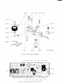
TA N D B E R G
Seri e s
SOOOX
MA N U A L
S ER VIC E
;
t ";'
ryr;
ir--I
ll "--: I
TANDAERG
*q
oc
reCOAO LEEL
ruc
"t
A
r
-
;
TANDBERGS RADIOFABRIKK A/S
-
-
A
^a
.G.
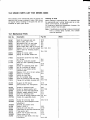
Contents
1.0 TECHNICAL SPECIFICATIONS
F
2.0 MECHANCIALADJUSTMENTS
2. 1 Cl u tc h e s .....:.
2.1.1 Take-up Turntable
2.1.2 Take-up Turntable
2.1 .3 S u p p l y T u rn ta b l e
2.1 .4 S u p p l y T u rn ta b l e
2.2 Brakes
2.3 Pressure Pad Adiustment . .
2.4 End Stop Mechanism .
2.4.1 Tape Feeler Tension
2.4.2 Adjustment of Tape Feeler
4
4
4
4
4
4
5
6
6
6
6
3.0 ALIGNMENT .
3.1 Demagnetlzing
3.2 Blas- and Erase Circuits
3.2.1 Oscillator Frequency . . .
3.2.2 Erase Voltage
3.2.3 Bias Current
7
7
7
7
7
7
4.0 TAPE PATH
4.1 Visual Check
4.2 Mechanlcal adjustment ol tape path . . .
8
8
8
5.0 HEAD ALIGNMENT WITH TANDBERG TEST
TAPES, MODEL 3041X
5.1 Playback head
5. 1 .1 H e i g h t Ad j u s tme n t
5.1 .2Az i mu th A d j u s tm e n t
5.2 Record Head .
5.2 .1 H e i g h t Ad l u s tme n t b y V i sual
In s p e c ti o n
5.2.2 Height Adjustment by Track
Me a s u re m e n t. ....
5.2 .3 .A z i m u th A d j u s tm e n t ...
5.3 Bias Head
5.3 .1 Ve rti c a l Ad j u s tme n t ....
5.3 .2 H e i g h t Ad j u s tme n t
5.3.3 Horizontal Adjustment
5.4 Erase Head .
5. 4 .1 H e i g h t Ad j u s tme n t
5.4.2 Azimuth Adjustment
5.5 Model 3021X .
9
I
9
9
9
9
I
I
10
10
6.0 HEAD ALIGNMENT WITHOUT TANDBERG
TEST TAPES, MODEL 3041X
6.1 Playback Head .
6. 1 .1 H e i g h t A l i g n m e n t
6. 1 .2A z i m u th Al i g n me n t . ...
6.2 Record Head .
6.3 Bias Head
6.4 Erase Head .
6.4.1 Height Adjustment
6.4.2 Azimuth Adjustment
6.5 Model 3021X .
10
10
10
10
10
10
10
10
10
10
I
I
9
9
9
9
7.0 TRACK CONTROL
7.1 Model 3041X .
7.1.1 R ecord H ead
7.1.2 Erase Head .
7.1.3 P l ayback H ead
7.2 Modell 3021X .
7.2.1 Erase Head .
7.2.2 Record Head
7.2.3 Playback Head
10
10
'10
10
11
11
11
11
11
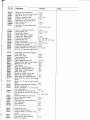
8.0 ADJUSTMENT AND CONTROL OF
TH E A MP LIFIE R S
. . . 11
8.1.1 P l ayback Level A dj ustment . . . . . . 11
8.1.2 A dj ustmentof B i as C urren t . . . . . . 11
8.1.3 Record/PlaybackLevel Adiustment 11
8.1.4 R ecord/P l aybackC urves .. . . . . . . 11
8.1.5 D i storti on
.. . . . . . .
11
8.1.6 C ontrol of P l aybackA mpl if ier . . . . 1'l
8.2 Tape S peed C ontrol
. . . . 12
8.2.1 U si ng FrequencyMeter or Count er 12
8.2.2 Using Transformer and Vacuum
Tube V ol tmeter
.. . . . . . . . 12
8.2.3 U si ng Tape of K now n Len gt h . . . . 12
9.0 R E C OR D /P LA Y B A C K
CURVES
.....
9.1 Readjustment ol Record/Playback Level
9.2D l stortl on....
.. . . . . . . . 12
9.3 Control of Playback and Record
A mpl i l i ers
.... ...
9.3.1 P l ayback A mpl i fi er
.... ...
9.3.2 R ecord A mpl i fi er
... . . . . . .
1 0 . 0Mo DrF t c A T ro NS
12
12
12
12
13
... 15
10.1 Modilications from 11511301230/240
V,
50/60 Hz Operation
. .. . 15
10.2 Modification lrom Four-Track to TwoTrackV ersi on...
. . . . . . 15
10.3 Component Modification in Series 3000X 15
11. LU B R TC A TTON
.
......
15
12.0 ILLUSTRATIONSWITH REFERENCE
P A R T N U MB E R S ..
.....
16
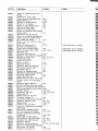
13.0 SPARE PARTS LIST FOR MODEL 3OOOX.. 22
13.1 Mechani cal P arts
. . . . . . 22
13.2 E l ectri ca! C omponents . .
. . . . . 26
14.0 TABLE OF TRANSISTORSUSED IN
MODEL 3OOOX
15.0 B LOC K D IA GR A M FOR MOD E L S OO O X
. . . . 28
16.0 PRINTED WIRING BOARDS AND WIRING
DIAGRAM
16.1 European Version
16.2 U.S. Version
28
30
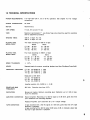
1.0 TECHNICALSPECIFICATIONS
POWER REQUIREMENTS: 115-130-230-240
c o n n e c ti o n s .
Wl
V. 50 or 60 Hz operation. See chapter 10.1 for voltage
POWER CONSUMPTION: 45 watts.
MOTOR:
Asynchronous.
TAPE SPEED:
17leips, 33/r ips and 7tlz ips.
TAPE:
Maximum reel diameter 7". Low Noise Tape only should be used for recordinq
and for adjustment procedure.
WIN DI NGT I M E S :
1 2 0 0 ft. o f ta p e ; 1 3 1 mi n.
1800 ft. of tape: 2t/z min.
PLAYING TIME,
MODEL 3021X:
Two track recording on
Stereo
7t/z ips: 48 min.
33/,rips: 96 min.
1 7 l ai p s : 1 9 2 mi n .
PLAYING TIME,
MODEL 3041X:
Four track recording on 1800 ft. of tape.
Mono
Stereo
71/zips: 2 x 48 min.
4 x 48 min.
33/r ips: 2 x 96 min.
4 x 96 min.
1 7 l ei p s : 2 x 1 9 2 mi n.
4 x 192 mi n.
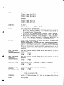
SPEED TOLERANCE:
-+ 1,50/0.
HEADS:
Separateheads for erasure,recording, playback and bias (TandbergCross-field).
cl
A
1800 ft. of tape.
Mono
2 x 48 min.
2 x 96 min.
2 X 192 mi n.
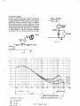
FREQUENCYRESPONSE: 7t/z ips: 40-20.000 Hz -+ 2dB
33/r ips: 50-16.000 Hz -+- 2dB
17e ips: 50- 9.000 Hz -+ 2dB
M e a s u re dto D IN 4 5511:
7t/z ips: 4O-22.0O0Hz
33/r ips: 40-18.000 Hz
17laips: 40-10.000 Hz
C
!
(
fi
(
Amplifier position: 50-18.000 Hz -+ 3 dB
ERASE AND BIAS
FREQUENCY:
85,5 kHz. Distortion less than 0,5 %.
INDICATORS:
Moving coil meters. Optimum recording level: Deflection up to 0 dB at maximum 3 o/odistortion.
AMPLIFIER DISTORTION: Record Amplifier: Recording of a 400 Hz signat at 0 dB level, gives less than
0,5 0/odistortion from recording amplifier.
Playback Amplifier: 0,3 0/odistortion at 0, 75 V output voltage.
TAPE DISTORTION:
A tape recorded with a 40OHz signal at 0 dB level, gives less than 30/o tape
distortion in playback.
A tape recorded with a 400 Hz signal 8 dB below 0 dB on indicator, gives less
than 0,8 0/otape distortion in playback.
i
-
WOW:
W. R . M. S.:
7t/z ips - better than 0,07o/o
33/r ips - better than 0,140/o
17leips - better than 0,280/o
D tN 4 5 5 1 1:
71/z ips - better than 0,1 o/o
33/r ips - better lhan O,2o/o
17leips - better than 0,40lo
CROSSTALK
ATTENUATION:
At 1OOOHz:
Mono ) 60 dB
INPUTS:
Each channel has the following inputs:
1. Microphone input for dynamic low impedance microphone. lmpedance:
200-700 ohm. Sensitivity at 400 Hz: 0,1 mV. Maximum input level: 25 mV.
DIN socket. US-version,Telephone jack.
2. Line input for high impedance source. lmpedance: 1 Mohm. Sensitivity at
400 Hz: 100 mV. Maximum input level: 20 V. Phono sockets, LINE lNpUTS.
3. Line input for low impedance source. lmpedance: 57 kohm. Sensitivity at
400 Hz: 5 mV. Maxirnum input level: 1 V. DIN socket RADIO: Pin 1, left
channel: Pin 4, right channel. US-version:Phono sockets LOW lN.
OUTPUTS:
Emitter follower outputs, RADIO DIN socket pins 3 and 5. US-version: phono
SocKetS,OUTPUT LEFT and RIGHT.
Minimum load impedance: 100 ohm. Output level: A tape recorded with 400 Hz
signal at 0 dB level, gives approx. 0,75 V in playback. HEADPHONES,stereo
jack for connection of headphones.
Stereo jack is connected in parallel with RADIO socket pins 3 and 5. On USversion stereo jack is connected parallel with phono sockets OUTPUT LEFT
a n d R IG H T .
a
Stereo )
SO OA
SfGNAL TAPE/NOISE
Peak value measured according to DIN 45511 at tape speed 71/z ips and 5olo
WEIGHTED
tape distortion:
(GERAUSCHSPANNUNG): 4-track
2-track
54 dB
56 dB
SIGNAL TAPE/NOISE
UNW E I G HTED
(FREMDSPANNUNG):
Peak value measured according to DIN 45511 at tape speed 7t/z ips and 5o/o
d i s to rti o n :
4-track
2-track
51 dB
51 dB
SIGNAL/TAPE NOISE:
Measured linear R.M.S. at tape speed 7'lz ips and 5 o/o distortion:
4-track
2-track
57 dB
s7 dB
SfGNAL/TAPENOISE:
Measured at tape speed 7t/z ips and 5 0/odistortion:
Wetonreo
(lEC A-CURVE)R. M. S.:
4-track
z-track
62 dB
64 dB
Note: At 3 0/o distortion all signal to noise ratio measurements (Signal/tape
noise) are reduced by 2 dB.
DfMENSIONS:
Length: 151/2"(39,4 cm), heigth: 6t/2" (16,5 cm) and depth: 123la" (31,6 cm).
W E I G HT :
2 0 l b s (9 ,1 k g ).
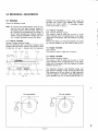
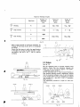
2.0 MECHANICAL
ADJUSTMENTS
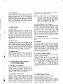
2.1 Glutches
C o n tr ol of W inding To rq u e
Note: All controls and measurementsmust be carried out with the tape recorder placed in
horizontal position and with empty reels only.
All controls are accomplished as shown in
tig. 2.2 which presents two optimal modes of
control. Take-up turntable is shown. By control of supply turntable, reverse the figure.
2.1.1 Take-up Turntable
Normal Forward Winding Torque
Set the operating lever to Normal Forward drive
position v.riththe motor running. The torque is read
in table tig. 2.3, pos. 1. Ensure that the clearance
9910r3
2.1.2 Take-up Turntable
Fast Forward Winding Torque
The torque is read in table fig. 2.3, pos. 3. lf the
torque deviates from the specificationsin the table,
check and, if necessary,alter the pressure of spring
263737B.
Ensure that there is a clearance between the studs
on bushing 2640834 and lever 991013.See fig. 2.4.
*
1
Pot
2
Po
3
2.1.3 Supply Turntable
Tape Tensi on
The torque is read in table fig. 2.3, pos 2.
,l
0. 5 - 0 , 9 m m
(0. 02 t '- 0 . 0 3 5 ' )r
991017
between the polyurethane friction pads under the
turntable and friction disc 991009 lays between
0,5--O,9 mm (0.02"-0.035"). lf necessary, adjust
screw A as show n i n fi g. 2.1.
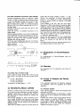
2.1.4 Supply Turntable
Fast Reverse Winding Torque
The torque is read in table fig. 2.3, pos. 3. lf the
torque deviates lrom the specifications in the table,
check and, if necessary,alter the pressure of spring
2618054.See fig. 2.5.
261841
2673?38 2640834' 991009
Fig. 2.1 .
I
a
I
i
(
i
The difference between Fast Winding Torque and
Fast Reverse Winding Torque should be less than
1309 (measuredat 30 mm radius),or 509 (measured
at 80 mm radius). lf necessary,alter the pressure ot
spring 261805A(fig. 2.5), or spring 2673738(fig. 2.1).
80 mm radius
30 mm radius
Fig 2.2.
t
t
Tabl e for W i ndi ng Torques
Torque at
30 mm
radius
tit
Torque at
80 mm
radius
winding
159- 309-
Pos
tape rensron
2
o-
Pos
F as t w i n d i n g
3
8g
909-250g
t
Fig. 2.3.
* After a longer periode
of continuous operation, an
increase of the torque by 2G-30 0/ois considered
as normal.
Ensure that the torque is within the specifications
in the table by running the tape recorder in vertical position, and with a tull 7" reel on take-up
turntable.
C
264930
9 9 10 1?
Fig. 2.6.
2.2 Brakes
See fig. 2.6
I
mi n 0,l mm
(0.004,')
Fig. 2.4.
Set the operating lever to Normal Forward drive
position. Check that the clearance between the
brake pad and the turntable is approx 1 mm (0.04").
lf necessary,adjust screw D.
Set the operating lever to Fast Forward Winding or
Fast Reverse Winding position respectively.Ensure
that the clearance between screw C and the bottom
of the hi nged del ri n parts on operati ng ar m 991017
lays between 0,5-1 mm (0.02"-4.O4"). lf necessary,
adjust screw C.
The adj ustment procedure i s equal for b ot h t ur ntables.
251489A
@
2 6 18 0 5 A
Fig. 2.5.
Fig. 2.7.
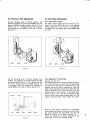
2.3 PressurePad Adjustment
2.4 End Stop Mechanism
Set the operating lever to Neutral position. The
clearance between the pressure pad 990325 and the
tape rest 254844Ashould be approx. 6,5 mm (tlr") as
shown in fig. 2.7. lf necessary,adlust the clearance
by bending the arm 254025 with a pair of pliers.
See fig. 2.8.
2.4.1 Tape Feeler Tenslon
The feeler tension against the tape should lay between 8 and 10 g (0.28-0.35 oz) in drive winding
modes. Adjustment of the tension is accomplished
by tightening or slackening the spring 243990.See
lig. 2.12.
I
l1
a
(
t
a
Fig. 2.8.
Fig.2.10.
I
a
Set the operating lever to Normal Forward drive
position. The pressure at the pad against the tape
rest should be 80 g (2,8 ozl -+ 10 0/0,measuredon the
end of the pressure pad arm 254025.See fig. 2.9.
lf necessary, adjust the pressure by bending the
sp r ing 268062wi th a p a i r o f p l i e rs . S e e fi g . 2 .10.
252754
zzl
8 0 s 12.82ozl !
2.4.2 Adjustmenl of Tape Feeler
S ee fi g. 2.11 and 2.12.
Set the operating lever to Normal Forward drive positi on. The mai ns sw i tch i s set to ON . N o tape should
be inserted.The tape feeler will therefore rest in the
position where the motor is switched off. Push the
feel er sl ow l y through the gui de post. W hen the r ear
si de of the feel er i s mi n. 0,5 mm (0.02" ) from t he
polished tape contact surface of the guide post,
loosen screw F, and move the microswitch slowly
until the motor starts when the tape feeler is in the
position specified above. Then tighten the screw.
l,
/:\
(@,
a-\\
',-/
tM3 l 4
Fig. 2.9.
When the tape feeler is released, the microswitch
should open, and switch off the motor current when
the space between the tape feeler and the arm
See fig. 2.12.
266741is minimum 0,5 mm (O.O2").
Check the switching on and-off positions of the
tape feeler at both fast winding modes.
Adjustment distance
minimum 0,5 mm (0,02rr)
Juste ringsavstand
266741
Min 0,5 mm
(o.02"l
243990
Fig. 2. 11.
v
Fig. 2.12.
3.0 ALIGNMENT
3.2 Bias- and Erase Circuits
It is important that the contact between the tape
and the heads on the tape recorder is good. To
obtain optimum results on new tapes (Low Noise),
the tape should be run through the tape recorder
approx. 5 times at normal speed to have the tape
polished before measuring the frequency response
and the signal-to-noiseratio.
3.2.1 Oscillalor Frequency
Connect a calibrated long wave receiver (tuned to
256.5 kHz), frequency meter or frequency counter to
the oscillator by means of a pick-up loop placed
around the erase head. Adjust the oscillator
frequency to 85.5 kHz by means of C 508.
3.1 Demagnetizang
Demagnetizethe heads and adjacent parts before
aligning the heads.
Move the demagnetizingcoil slowly past the head
gap at short distance.The head surface must on no
account be touched, as scratches are detrimental to
the performance.Hold the demagnetizing coil near
the capstan for a few seconds.
Start the tape recorder and hold the demagnetizing
coil right above the flywheel.
Note: Do not switch off the demagnetizer until it is
at least 3 feet away from the tape recorder.
3.2.2 Erase Voltage
Set the tape recorder for stereo recording and
connect a VTVM to upper half of the erase head
by means of a low-capacitance probe. The voltage
shoul d be 80-120 V . Then check i hat t he sam e
voltage appears across lower head-half.
Set the tape recorder for recording on channel L
and check the voltage across upper half of the
erase head. The deviationfrom the voltage measured
in stereo recording should not exceed 10 V. Proceed
si mi l arl yfor recordi ng on channel R .
3.2.3 Bias Current
Set the tape recorder for stereo recording and
measure the voltage across upper half of the bias
head by means of a VTVM. Adjust the voltage to
22 Y by means of R 501. Check the voltage across
lower head-half and adjust to 22 Y by means of
R 502. Demagnetize heads and tape path.
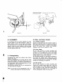
4.0 TAPE PATH
4.1 Visual Check
Load the recorder with a tape, and move the
operating lever slowly to the normal forward drive
position. Check that the bias head neither touches
the height adjustment screws (C) on the record
head base plate, nor presses the tape against the
record head. Also check that the bias head is
parallel to the record head.
Operate the start/stop knob, and check that the
tape runs within the rims of the pressure wheel
rubber without flickering on neither side of the
pressure wheel. Check that height positioning of
the guide posts is correct. lt can be tolerated that
the tape touches the flanges of the guide posts
when the recorder is in normal forward drive, or
as the drive mechanism is engaged. The tape must,
however, by no means bulge at the flanges.
through the rest of the tape path, slightly touching
one of the flanges of the guide post 1 located
adjacent to the capstan.
Align guide posts 2, 3, and 4 similarly. lf necessary,
adjust pressure roller spring 234478to make the tape
run perfectly.
$,
a
tc
5
P
pl
al
al
hr
o
el
(
tt
5
P
p
a
b
ir
4.2 MechanicalAdjustmentof Tape Path
Prior to the electrical adjustment of the heads, it is
essential to make the tape run without sideways
movement through the path.
Put a tape free from damages on the recorder in
normal way and set the operating lever to normal
forward drive position. Adjust the azimuth position
of pressure roller 990334 with a screw driver as
shown in tig. 4.2, until the tape is running evenly
5
990334
Fig. 4.2. Azimuth adiustment ol pressure roller.
E
5
Ir
4
ft
tt
h
n
v
tt
I
F
C
(
c
v
I
(
I
I
I
MD
Fig. 4.1. Tape path adiustment screws.
5.0 HEAD ALIGNMENTWITH
TANDBERGTEST TAPES,
MODEL 3041X
rg
)d
v,
)e
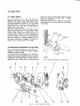
5.1 Playback Head
5.3 Bias Head
Set the recorder for stereo playback and connect
a VTVM to each one of the outputs. Output selector
to position STEREO.
5.3.1. Vertlcal Adjustment
Move the operating lever slowly
forward drive position and check
fronts of bias- and record heads
necessary, bend the arm of the
requi red.
5.1.1 Helght Adiuslment
Play Tandberg test tape No. 1. This is a full track
prerecordedtape with 1.000Hz recorded at 71/zips,
and with area correspondingto track 3 reduced by
approx. 30 dB. Adjust the height of the playback
head by m e a n s o f th e s c re w s (A) u nti l mi ni mum
output is obtained from track 3 (channel R), while
endeavouringto maintain the headfront parallel to
the tape.
5.1.2 Azlmuth Adjustment
Play Tandberg test tape No. 2. This is a full track
prerecordedtape with 10.000or 15.000Hz recorded
al 7t/t ips. Adjust the azimuth position of the playback head by means of the screw (B), until maximum
indication on the VTVM is obtained.
5.2 Record Head
5.2.1 Height Adiustment by Visual Inspectlon
Insert a new tape, and start the recorder in normal
forward drive. Check visually that the tape appears
to run parallel with the upper track of the record
head, with a play of approx. 0.1 mm (4 mils). lf
necessary,adjust the height with screws (C) fig. 4.1,
while endeavouringto maintain the headfront parallel
to the tape.
5.2.2 Height Adjustment by Track Measurement
Record in stereo, well above normal level, first in
one direction, then in the opposite. Cut off a length
of t ape and d i p i t i n to a s o l u ti o no f fi n e grai ned i ron
oxyde powder and alcohol (Magna See). The tracks
will t hen by v i s i b l e a s fo u r d a rk s tri p e swi th spaci ngs
in lighter shade. Fig.7.1 shows the correct pattern
on the tape and the patterns obtained when the head
is positioned either too high or too low.
Adjust as above and perform a new track measurement.
5.2.3 Azimuth Adjustment
Load a new tape into the tape recorder and record
at tape speed 7tl2 ips a 15.000Hz signal in stereo.
Set OUTPUT selector to position STEREO. Adjust
both RECORD LEVEL knobs for approx. 150 mV at
the output. Adjust the record head azimuth screw
( D) f or m a x i mu m o u tp u t fro m b o th c h a nnel s si mul taneously,or best compromize.
to the normal
that the head
are parallel. ll
bias head as
5.3.2 Height Adjustment
Set the tape recorder in stereo record mode, and
unscrewthe l ocki ngscrew (H ) fi g. 4.1, about r / z t ur n.
Connect a VTVM across each one of the record head
halves. Move the bias head up or down by means of
adjustmentscrew (M) for the highestpossible reading
on the voltpeter. Check that the tape runs freely in
the groove in lront of the bias head and that there
is sufficient clearance between the bias head and
the mounting plate for the record head. The height
position of the bias head is not critical, and if the
clearance between the bias head and the mounting
plate for the record head is insufficient, raise the
bi as head sl i ghtl y.
5.3.3 Horlzontal Adjustment
Connect a VTVM across each one of the record
head-halves,and set the tape recorder for stereo
recording. Insert a screwdriver in groove l, ref.
fi g. 4.1, and pul l the bi as head to the ri gh t .
Then pull the bias head carefully by means of the
screwdriver towards the left hand side. lnduced
voltage (bias) in recording head increases to a
maximum. Continue pulling the head towards left
si de unti l the bi as i s reduced by 10-1 50/ o below
maximum. When the position has been found,
tighten the screw (H) while maintaining correct
horizontal position of the head. Then recheck the
output voltage. lf a noticeable change has occured,
the horizontal procedure has to be repeated.
5.4 Erase Head
5.4.1 Helght Adjustment
By visual inspection, check that approx. 0.25 mm
(10 mils) of the upper half of the erase head is
visible above the tape. Insert Tandberg test tape
No. 9 and record a 400 Hz signal at 7tlz ips well
above normal level on channel R (track 3). Dip the
tape in a solution of fine grained iron oxyde powder
and al cohol (Magna S ee sol uti on). C he ck t hat t he
recorded track is positioned in centre of the erased
track. Make sure that no parts of the adjacent tracks
are erased, see fig. 7.2. lt necessary, adjust the
height of the erase head by means of the screws (K)
and (L) ref. fi g.4.1, and repeat the above check.
5.4.2 Azlmuth Adjustment
Check that the head front ol the erase head is
perpendicular to the mounting plate. lf necessary,
adjust azimuth position by means of the. screws (K)
ref. fi g. 4.1. Thi s adj ustmenti s not cri ti cal.
<
5.5 Model 3021X
The alignments specified in para. 5.0 are valid for
the model 3021X with the exception of paragraph
5 . 1. 1,whic h is s u p e rs e d e d b y 6 .1 .1 a n d p a ragraph
5 . 2. 1, whic h is s u p e rs e d e db y 7 .2 .2 .
6.0 HEAD ALIGNMENTWITHOUT
TANDBERGTEST TAPES,
MODEL 3041X
6.1 Playback Head
6.1.1 Helght Alignment
The height of the playback head is aligned by the
height adjustment screws (A), ref. fig. 4.1. The upper
edge of the tape shall run flush with the upper part
of the head lamination for channel L.
6.1.2 Azimuth Alignment
Set OUTPUT selector to position STEREO.
Play back a standard azimuth alignment tape with
a VTVM connected to each output. Adjust the position of the playback head by the azimuth adjustment
s c r ew ( B ) r ef. fi g . 4 .1 , u n ti l ma x i mu m readi ng i s
obtained on the output meters.
7.0 TRACK CONTROL
7.1 Model 3041X
7.1.1 Record Head
Record a 1.000Hz signal from a generatorwell above
optimum recording level in stereo. Record on tracks
1 and 3 for approx. 5 seconds. Turn the tape and
make a si mi l ar recordi ng on tracks 4 and 2. Cut
the tape and dip it into a mixture of fine grained
iron oxyde powder and alcohol (Magna See solution)
to make the recording visible. The spaces between
the recorded tracks should be distributed equidistant
across the tape, ref. fig. 7.1. Readjust the height
position, if necessary, and recheck the azimuth
al i gnment.
7.'1.2 Erase Head
lnsert a full-track prerecorded tape and record a
1.000Hz signal from a generator,well above optimum
recordi ng l evel i n mono on track 3 (channelR) . Cut
the tape and di p i t i nto the Magna S ee solut ion.
Check that the prerecorded track is in the centre
of the erased area, ref. 1i9.7.2. Adjust the vertical
position of the erase head if necessary.
6.2 Record Head
Follow the instructions given under paragraph 5.2.
Too high.
Too low.
6.3 Bias Head
Follow the instructions given under paragraph 5.3.
6.4 Erase Head
6.4.1 Helght Adjustment
The height of the erase head is aligned by the height
adjustment screws (K and L) ref. fig. 4.1. Approx.
0. 25 m m ( 10 m i l s ) o f th e l e rri te c o re fo r t he upper
track of the erase head should be visible above the
tape.
6.4.2 Azimuth Adjustment
Align the azimuth position of the erase head by the
azimuth adjustment screws (K). The erase head
s hould be pa ra l l e l w i th th e mo u n ti n g p l a t e for the
heads. The azimuth position of the erase head is not
c r it ic al.
Correct
Fig. 7.1. Track measurement of record head.
Too high.
Too low.
6.5 Model 3021X
The alignments specified in paragraph 6.0 are valid
for model 3021Xwith the exception of paragraph 6.2
which is supersededby 5.2. Paragraph5.2.1is superseded by 7.2.2. Paragraph 6.4.1 is superseded by
7. 2. 1.
Cotrect
Fig. 7.2. Track measurement ol erase head.
te
(s
td
Tt
rd
t)
rn
It
It
h
2
n
t
t.
I
7.1.3 Playback Head
Rec or da 1 .0 0 0H z s i g n a l o n tra c k 1 (c h annelL) and
a 500 Hz signal on track 3 (channel R) well above
optimum recording levels. Set OUTPUT selector to
position STEREO. Turn the tape around and play
bac k t r ac k 2 (c h a n n e lR ). N o s i g n a l s h o ul d be heard.
Raise the playback head if the 1.000 Hz signal is
heard. Lower the playback head if the 500 Hz signal
is hear d. R e c h e c kth e a z i mu th p o s i ti o n.
7.2 Model 3021X
7.2.1 Erase Head
The height of the erase head is aligned by the
adjustment screws (K and L) ref. fig. 4.1. Record
a 1.000 Hz signal in stereo well above optimum
recording level on a full-track prerecorded tape. Dip
the tape in the Magna See solution and check that
the tracks are distributed symmetrically across the
tape. Readjust the erase and the record heads, if
necessary.
I
7.2.2 Record Head
The height of the record head is aligned by the
height adjustment screws (C). Record a 1.000 Hz
signal in stereo well above optimum recording level
on a full-track prerecorded tape. Dip the tape in
Magna See solution and check that the tracks are
distributedsymmetrically across the tape. Readlust
the erase and the record heads. if necessarv.
7.2.3 Playback Head
The height of the playback head is aligned by the
height adjustment screws (A). The tape shall run
par allel wi th th e u p p e r e d g e o f th e l ami nati on for
channelL. Readjustthe azimuth position if necessary.
8.0 ADJUSTMENTAND CONTROL
O F TH E A MP L IF IE R S
8.1.1 Playback Level Adjustment
Connecta VTVM to each one of the outputs, and set
OUTPUT selector to position STEREO. Set the
recorder lor 7t/z ips playback of Tandberg test tape
No. 4 and adjust R451 (L) and R351 (R) for 0.7 V
reading on both vacuum tube voltmeters.
8.1.2 Adjustment of Bias Current
Insert a new reel of good quality tape (Low Noise).
Connect a VTVM to Output terminals, and signal
gener at or to H IGH In p u t te rm i n a l s a nd set the
generator for 1.000 Hz and 0.5 volt. Set output
selector to STEREO. Set the tape recorder for
stereo recording. Adjust the Record Level Control
to 75 mV deflection on VTVM. Adiust R501 to maxi-
mum deflection on left channel VTVM, and R502 to
maxi mum on ri ght channel V TV M.
Note: The 2-lrack model is also equipped with
i ndi vi dual l y tuned bi as- and erase heads.
The values ot C5O2,C503, C515 and C516 are
labelled on the bias- and erase heads respectively. The capacitances are given in pF.
Upper number refers to upper track.
8.1.3 Record/Playback Level Adjustment
Connect a VTVM to each one of the outputs. Insert
a new tape and record a 400 Hz signal from a generator at 7t/z ips in A-test. OUTPUT selector to positi on S OU R C E .A dj ust the i nput l evel s for a VTVM
indication of 0,7 volt at both outputs. Adjust R433
for a 0 dB reading on left record level indicator and
R333 for the same reading on right indicator. Set
OUTPUT selector to position STEREO and adjust
R451 (L) and R351 (R) to 0,7 V indication on VTVM.
8.1.4 Record/Playback Curves
Ref. paragraph 9.0 for control of record/playback
curves.
8.1.5 Dlstortion
Connect signal generator,400 Hz 0.5 V, to High Input
and distortion meter to outputs. Record in B-test on
both channels.OUTPUTselector to position STEREO.
Set the tape recorder for stereo recording. Adjust
Record Level controls to 0 dB deflection on indicators. Check distortion to be less than 3 0/0. lf
distortion exceeds 30/o readjust recording level and
indicator, ref. paragraph 8.1.3.
8.1.6 Control of Playback Amplifier
Connect a VTVM to each one of the outputs.OUTPUT
selector to position STEREO.
Play back Tandberg test No. 3. This is a full track
prerecorded tape w i th the fol l ow i ng frequencies:
250-10.000-5.000-1.000-100-50-250 Hz recorded
at 71/z ips tape speed. The tape conforms with the
N . A . B . standard.The output tol erancesa r e: 10 kHz:
+ 4 dB , 5 kH z
1 - + 3dB . The ot her f r e0quencies have tolerances
t 2 dB. The difference
in level between the two channels should be less
than 3 dB .
8.2 Tape Speed Control
8.2.1 Using Frequency Meter or Counter
Set OUTPUT selector to position L.
Connect a frequency meter or counter to Output L
and play back Tandberg test tape No. 11 (1.000Hz)
at 7tlz ips tape speed. Difference from correct tape
speed is indicated in 0/0.Tolerance: -r- 1,50/0.
8.2.2 Uslng Translormer and Vacuum Tube Voltmeter
Connect a transformer 115/0.SV or 230/0.5V, 50i60
Hz and a WVM to Output and the mains as shown
in fig. 8.1, dotted line indicates phono socket on USversion. Set OUTPUT selector to position L. Play
back Tandberg test tape No. 10 a (mains frequency
50 Hz) or No. 19 a (mains frequency 60 Hz) al 71/z
ips tape speed.
Deviation from correct tape speed will give a beat
across the VTVM.
C loc k t he t im e fo r 1 0 c o m p l e te e x c u rs i o n s of the
meter needle.
Read the speed deviation in per cent corresponding
to this particulartime from the nomogram in fig. 8.2.
Brake left hand turntable slightly to decide if tape
speed is too high or too low. Increased deviation
indicates too low tape speed.
At 33/r ips, play Tandberg test tape No. 10 b (50 Hz
mains frequency). Proceed as for 71/z ips to tind
speed accuracy.
S peed t oler ance : + 1 ,5 0 /0 .
check that the output voltage is within )- 2 dB.
Perform fine adjustment of record head azimuth
position. lf the voltage is too high, increase bias
current by means of R501 for channel L and R502
for channel R .
lf the voltage is too low, alter the input signal
frequency to 1.000Hz and adjust for maximum output
voltage by means of R501 and R502 for channels L
and R respectively.Then go back to 400 Hz, establish
the reference level. and recheck the output level at
16.000Hz. When the tolerance at 16.000Hz has been
met, check that the output level at frequencies between 50 and 16.000 Hz do not deviate more than
-+ 2 dB from reference level.
Perform the same check for 7tlz ips at freguencies
between 40 and 20.000 Hz, and then finally check
lor 17/a ips between 50 and 9.000 Hz. Ref. level
400 Hz.
The output levels of the two channels should not at
any frequency differ by more than 3 dB.
9.3
Cc
thr
a
Sh
Se
ler
do
on
on
ac
v.T .v.M
9(
oulSu
'
|.uuo
,oo
,,
For readjustments of Record/Playback level ref.
paragraph 8.1.3.
Fig. 8.1
3.0 2,5 2p
r,5
'
+d1l!l-,t,,,
r,0
0,5
0,1
|
|
I
tl
15
20
25
30
9.1 Readjustment of Record/Playback
level
r0
0,3
lSpeeddevioiion{'/.)
Time in sonds
I-I-IJ
for l0 complete
50 60 66 excursions.
Fig. 8.2.
8.2.3 Using Tape of Known Length
Insert a tape of known length 450" (1144 cm) and
play it bac k . T im e ta k e n fo r th e w h o l e l e n g th shoul d
b e:
71lz ips: 60 seconds
331 ips : 12 0 s e c o n d s
17laips: 240 seconds
Toler anc ef or al l ta p e s p e e d s : + 1 ,5 0 /0 .
9.0 RECORD/PLAYBACKCURVES
Connect a WVM to each one of the outputs L and
R. ln order to avoid interlerence from the oscillator
voltage, a band stop or a low pass filter tuned to
85.5 kHz must be inserted between the outputs and
the voltmeters.
Set the tape recorder for stereo recording al 33/t
ips in B-test (STEREO) and record on Low Noise
Tape a 400 Hz signal at a recording level 30 dB below
optimum (0 dB). Use the output VTVM readings as
reference levels.
Then record a 16.000Hz signal at the same level and
9.2 Distortion
Ref. paragraph 8.1.5 for adjustment and control of
distortion.
9.3 Control of Playback and Record
Amplifiers
lf the specified tolerances for frequency response
are exceeded, check the playback and record
ampl i fi ers.
9.3.1 Playback Amplifier
lnsert a 22 ohm resistor in series with playback head
and junction 52 (59).
Connect a signal generator in series with a 1 kohm
resistor and a 100 pF capacitor and playback head,
see fi g. 9.' 1.
Connect also VTVM to each of the outputs and set
output selector to position STEREO. To ensure
correct signal response, apply oscilloscope. Tune
the generator to 400 Hz and adiust the level 20 dB
below 0.75 V, i.e. 75 mV. Check the frequency
response according to tig. 9.2.
t-
9.3.2 Record Amplilier
Connecta VTVM to a 100 ohm resistor in series with
the record head and ground as shown in fig. 9.3 and
a signal generator to HIGH Input for each channel.
Shortcircuit trimming capacitor C508 in oscillator.
Set the tape recorder for stereo recording. Set the
lev el30dB bel o w 0 d B i n d i c a to rd e fl e c ti o ni.e. 10 dB
down by meansof Record Level Controls,20 dB down
on signal generator, and use 400 Hz as reference
on VTVM deflection. Check the frequency response
according to tig. 9.4. Remove shortcircuit of C508.
R3 3 2 ( R1 3 2 )
VTVM
(o105)
Fig. 9.3.
s2(s9)
Signol
generqtor
F ig . 9 .1
Comp on en tsc onnec t edot :
Q - ott top e s peeds
a
- Ttlz ips
O - 33 /1 ip s
- t7 l8 ip s
Fig. 9.2. Playback ctJrves.
10
10
dB
26 r
I
2t,
Th
ac
11
22
w1
20
m(
t8
ilr
50
60
W
to
11
12
10
|'
o
1
I
L
0
500
1000
2000
s000
10000
c413.R 426
c 4t6,c417,R
c4r5,R 430
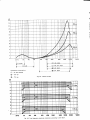
C o m p o n e n t s c on n e cte d q t
c414,R429
Q - o l t t o p e sp e e d s
O - 33 ii ip s
Fig. 9.4. Record curves.
O - l7 l8 ip s
dB
6
t,
2
0
6
L
2
0
6
t,
'2
0
20Hz
50
lO0
2m
5OO
IOOO 2000
5000 t0000 20000
Fig.9.5 Total lrequency responsetolerancesaccording to DIN 45511'
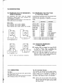
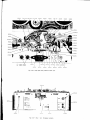
a-10.0MoDtFrcATtoNs
10.1 Modificationfrom 115/130/230/240V. 10.2 Modificationfrom Four-Track
to Two-Track Version
50/60 Hz Operation
The transformer and motor must be rewired
according to figures below when changing from
115/130/230/240
V operation.
When modifyingfrom 50 to 60 Hz or vice versa, the
m ot or pulley h a s to b e c h a n g e d .
The following components have to be changed when
modifying from lour-track to two-track.
Value of total capacitance is labelled'on two-track
heads.
Part
Motor pulley:
50 Hz operation, part number: 243940C
B
60 Hz operation, part number: 248351
W hen or der i n g mo to r p u l l e y , s p e c i fy p a rt number.
Record Head
Record Head
Playback Head
Erase Head
Erase Head
Bias Head
R432
R332
c515
c516
c502
c503
o- - - {
240V50Hz
Two-track
c04-11R "
F53-11R*.
c03-10P
D84-18EG51-18E ..
D90-038
5,6kohm
5,6kohm
250pF
250pF
3300pF
3300pF
F82-07R
F82-07R
F83-11P
D87-20E
D87-20E
D92-048
2,7kohm
2,7kohm
l A dd capacit ance
(unti l l abe lled
(capacitance
Jis obtained
* Valid on models below serial No. 2733300
-- Valid on models above serial No. 2733300
10.3 ComponenlModification
in Series 3000X
----l
go
L- - - -
1 l 5 V5 0Hz
l30V 50 Hz
Fig. 10.1. Motor and translormer connections.
1 1 . 0L U BR IC A T ION
The Motor:
The motor should be lubricated after approximately
every 3000 hours of use.
The upper and the lower bearing should be lubricated
with a Teresso oil 43 or 47 from Esso.
O Transistor Q503 is changed from type BC147B
to BC107B. Resistor R505 is changed from
2.2 kohm to 1 kohm. Both modifications are
introduced from serial number 2741500.
O R 116 and R 216 are changed from 1 kohm t o
220 ohm. C109 and C209 are changed from
6800 pF lo O,O22pF. Both modificationsare introduced from serial number 2744100.
The Sell Lubricating Bearings:
The turntables,the flywheel and the speed transferw heel are mounted i n sel f l ubri cati ngbearings and
shoul d usual l y not be l ubri cated. l f, however , it
should be necessary to lubricate the bearings for
any reason, use Teresso oil 43 or 47 from Esso.
Note: Utmost care must be taken while lubricating.
U se onl y one fracti onal drop of oi l f or each
bearing. Excessive oil might seriously affect
the triction drive.
-
WITH
12.0 ILLUSTRATIONS
PART NUMBERS
REFERENCE
264248 261655
991038 260?00
261655
991039
263688 262322
I
I
t
264435
261303
264786
274535
2633
269255
272854
260641
268
277523
262984
-r'
264665
V E B T . MOIjNT.
262M4 TEAK
264564ROSEWOOD
269??2WALNUT
262984
264665 VERT. MOLJNT.
Fig. 12.1
991033
.
9910 0 8 .
991034
21981 6
2 19 8 1 6
260361A
991035
991010
991009
264083A
261805A'
2 61 84 1
2 618 4 1
204013---_____________
20a013------.-*<5
-r?-N
16l
=,
-T'
2r8767
/-
t'6t
,,@ ) ,
\=Z
Fig. 12.2. Supply turntable.
Fig. 12.3. Take up turntable.
--
215053
EI
2 6 6 0 87A
235420
247941
236045
210622
204 01 3
214270
214895
25
2L
25rl
990 33 4
$-,,nn,u
99
25
26
21 4 8 9 5
$-z4s'\so
2(
25
204 01 3
21
266791
260577
2622s8
207977
991406 C OMP LETE
Fig. 12.4. Pressure roller arm, assembly.
229565
263939
202r5r
207977
267768
202309
2610948
265 0 60 A
263932A
24.13124
24
Fig. 12.5. Upper mounting plate seen lrom underneath
2 5 4844
D84- 188
D90_03U C0.1_l1R
990233
"/
262481
240267A
264762
260290
24301 3
242503
990334
265060 A
268422
273407
266797
E U VERS.229565
LTS.
: 6r i\ 2?
VERS. 249630
:u3tri r | :c't,tl
I rruoc
I zt,cqsg I zacj z:o
I
991028
2 61460
2?3939
230183
269801A
z egqtz
21i 7416
Fig. 12.6. Tape path and ptessureroller arm
274762
IANOB€iC
IA'€
R€COiOER
rcm!
3a.r
a a Iooaaa
{ :aoa
r
vorrs ;3r: .
FiEO
.ii\ r;
L'i .-:
L
269 ?8 6
(]
rEF
a
irtl.O ai
{O
RIGHT
TAilDSEftesRAOlOraEpt{{ar5
LINE
'{PUTS
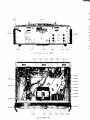
F ig . 1 2 .7 . Re ar
European version
qI
,l
-
991
990
O
o aaaaaaa
oaao
T^N08eRe
TAPTR€COqO€R
tooEl Jar;r I
991i
o
o
o
OO
f
volls
tr' {
FiEO . SC ia
o
I
L _ }R
}IORMAL
R +R
i9i9. i
991i
2701
2651
260
268221
20L
269902
2619704
Fig. 12.8. Rear view. U.S. version.
991402
264996
991046
260620A
2657354
212036
264578
262739
263 888
2e
211 339
Zl
?395
260289
254779
269902
252715
252496
Fig. 12.9. Bottom view.
241009
236159A 2490688
2483518 ( 60 H z )
243940C (50 Hz)
991 041
262969
262854
990204
9 9033019910431242331
2649?3
I 034
99 1 0 0 8
99 0312
I 014
99 10 1 4
99 1 0 1
991013
270821
240276A
26 5 0 9 6
266741
264270
260 0 4 5
263709
273134
20L95
263932
265060A
268 422
R 108
R 208
211418
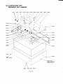
Fig
264054
26630e
267476
249630
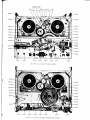
12. 10. Top view with covers removed
2605L2
26 3 6 0 1 A
2605L2
9 9 10 1 4
1920
262L93.
991014
99101
013
224795
r 015
25952
023
9529
1 031
261051
1 030
1 01?
R 1 08
9914 00
Fig
12.1 1
99t402
264996
990312
Top view with upper mounting
266238
pl ate removed
249630
-
Part
13.0 SPARE PARTS LIST FOR SERIES 3OOOX
The numbers of the mechanical parts on figures are
identical with the part numbers in store. Part shown
on figures without existing in the parts list are not
available as spare parts alone.
Ordering of Parts
When ordering a mechanical part, it is essentialthat
the appropriate part number being used as a reference in this manual, be specified.
For ordering of electrical components, however, the
posi ti on number must be used.
Note: lf modificationsaccording to list are introduced
from a certain serial number, this number
must be speci fi ed.
13.1 Mechanical Parts
lFig.Ref.
f fi'rl-l
n
201957
2A2008
202151
202309
203250
204013
207977
208724
209306
Shaft for pressure pad arm
M a i n s c a b l e . 1 1 5 V. 7 F T
Microswitch RX1 for end stop
Shaft for eccentric segment
Mains cable, 230 V 2?-Ocm w/olrrq
Washer, 7,5 x 4,2 X 0,5 mm
De l ri n ro l l e r fo r i n d e x i n g e c c e nt.
s eg me n t
Cla m p fo r m a i n s c a b l e
Spring for transfer wheel arm
12.10
12.8
12.5
12.5
12.7
12.2, 12.3, 12.4
12.4. 12.5
214895
215053
216734
218767
219234
219816
Adjustment screw for bias head,
3X 1 8 m m
P ul l e y fo r re v o l u ti o nc o u n te r
Shaft for lever operating press
pad arm
Ho l d e r fo r o p e ra ti n g l e v e r b a l l
Nu t fo r mo u n ti n g o f c a b i n e t
Screw for adj. plate, spring
pressure roller
Washer, 7,5 x 4,2 x 0,3 mm turbax
P ul l e y fo r tu rn ta b l e
S pri n g fo r c a m d i s c
Nut for turntable shaft
Shaft for pressure roller arm assy.
F la n g e fo r tu rn ta b l e h o u s i n g L &R
224795
229565
Support for PW board
DI N -c o n n e c to rfo r mi c ro p h o n e
12.11
12.5, 12.6
230183
2306298
234478
234960
235420
236045
236159A
S hi e l d fo r p l a y b a c k h e a d
Ro l l e r fo r s p e e d s e l e c to r a rm
Spring for bias head adjustment
Washer, speed selector knob.
Shaft for start/stop lever
Adj. plate for spring, pressure rol
Clamp for supporting motor.
12.6
12.7, 12.8
12.4
12.1
12.4
4.2, 12.4
12.9
240276A.
240406F'
12.6, 12j0
Screw for end stop lever
Spring for record-playbackhead
adjustment
Bracket for transfer wire
M o to r 1 1 0 /2 2 0V
12.9
S p ri n g fo r c a m d i s c a rm
12.10
T ap e fe e l e rfo r e n d s to p m e c h a ni sm 12.6
12.6
T ap e g u i d e , ri g h t
De l ri n a rm fo r b i a s h e a d a d j .
12.4
12.10
M o to r p u l l e y ,5 0 H z
S p ri n g fo r ta p e fe e l e r, e n d s to p
nrechanism
2.12. 12.5
210622
2'11339
211418
212036
212066
214270
2408794
241009
242331
242503
243013
243150
243940C
243990
12.4
12.9
12.10
12.9
12.4
12.4
12.3
12.2
12.6
12.2, 12.3
ltot""
2443
246,
2473
2479
zffi
248
2&
249
24fi
%1
251
252
252
252
252
zil|.
2il,
2il
257
259
259
259
260
260
260
260
26C
260
26(
26(
26(
26(
26
26
26
26
26
26
26
26
26
2C
2e
2(
2l
21
2
2
2l
2
2
2
z
a
I
a
a
Part No.
Description
244342A
246231
247395
247941
248027
248157
248351B
2490688
249630
Lever for end stop switch
Clamp for end stop swiich wires
Clip 9 mm (3 /e " )fo r v ri re s
Shaft for pressure roller
I ns ul a to r fo r e n d s to p s w i i c h
B us h i n gfo r a d j . o f ta p e g u i d e
M ot o r p u l l e y , 6 0 H z
Box for motor
Conn e c to rfo r m i c ro p h o n e a n d
head set
251130
2514894
252115
252172
252496
252754
254025
254779
254844A
257517
259529
259758
259773
260045
260289
260290
26A325
260361A
2605'12
260577
m0620A
260641
260700
260735
260929
260965
261051
2610948
261216
261303
261460
261525
261655
261805A
26'1841
261885
261920
261970A
261992
262021
262064
2621938
262258
262322
262402
262416
262481
262509
Lever for pressure pad arm
Tape support, left
E qua l i z a ti o ns w i tc h
Lower bearing for flywheel
Clam p , l i n k , e q u a l . s w i tc h
T ape g u i d e , a d j u s ta b l e
Pressure pad arm
Power transformer
Support for pressure pad & tape
Drive belt for counter
Lamp for counterand meter 24 V 1
Phono connector for input board
Bracket for fastening input board
I ns t r u me n t,re c o rd a n d p l a y b a c k
leuel i n d i c a to r
S ide p l a te , ri g h t
Tape support, right
Contact spring
Tape tightening disc left
Spring, brake lever left and right
B ear in g fo r fl u tte r fi l te r
Front panel
Knob for operating lever
Knob for cueing control arm
Tape guide, not adjustable
Rear cover plate
S pr ing fo r c u e i n g c o n tro l a rm
S oc k e t fo r l a mp , i n d i c a to r
I ndex g u i d e fo r o p e ra ti n g l e v e r
Adj. screw for clutch- and br
levers
Screw, 3 X 10 mm for front cover
plate
B ut t on fo r re c o rd i n g l e ft c h a n n e l
S t ud f o r l i fti n g a rm
S c r ew , j a p a n n e d , 3 X 1 0 m m
rear cover plate
Coil s p ri n g fo r left friction disc
Coil s p ri n g fo r c l u tc h - a n d b ra k e
levers
Screw for feeler arm, end stop
A r m , b ra k e ri g h t, a c e ta l
Bottom cover
T hr us t d i s c fo r fl y w h e e l b e a ri n g
A r m , bi a s h e a d
T eak c a b i n e t
M y lar s l i d e p l a te
F lut t er fi l te r ro l l e r
Knob for speed selector
Cont ac t s p ri n g fo r c o u n te r l a m p
holder
Shaft for start/stop knob
Tape braking arm, start/stop
S hield fo r i n d i c a to r
'12.5
12.5
12.9
4.2, 12.4
12.5
12.1A
12.9
12.6, 12.10, 12.11
12.6
2.7, 2.9, 12.6
12.9
12.9
2.7, 2.9, 12.6
2.7, 2.8, 2.9, 2.10, 12.6
12.9
2.7, 2.9, 12.6
12.9
12.11
12.7, 12.8
12.10
12.9
12.6
2.5, 12.2
12.11
12.4
12.9
12.1
12.1
12.6
' t2.1
12.11
12.5
12.1
12.6
12.1
2.5, 12.2
2.1, 12.2, 12.3
12.11
12.8
12.6
12.1
12.11
12.4
12.1
12.6
E
Part No.
Description
262545
Holder for speed selector arm
s pr in g
G r om me t fo r m a i n s c a b l e
Lower spring for operating lever
Speed selector arm
Bracket lor speed selector
Screw 5/e" lor cabinet
S pr in g fo r ta p e ti g h te n i n gd i s c
Uppe r s i d e p l a te , ri g h t
Bracket for power switch
Button for start/stop and function
select. switch
B r ac k e t fo r fl y w h e e l b e a ri n g
B ut t o n fo r re c o rd i n gri g h t c h a n n e l
Uppe r s p ri n g fo r o p e ra ti n g l e v e r
Arm, brake left, acetal
Screw 3 X 8 mm c.sunk for rear
cover plate
Button for power switch
B us h i n g fo r o p e ra ti n g l e v e r
Power switch without button
Guide for power switch button
S ide p l a te , l e ft
S pr in g fo r b i a s h e a d a rm
S pr in g fo r c l u tc h ,ta k e u p tu
B us h i n gfo r fri c ti o n d i s c
Rubb e r ta p e b ra k e
G uid e fo r s l i d e a rm
B ut t o n ,v o l u me
Rev o l u ti o nc o u n te r
S lee v efo r s l i d e a rm d a mp i n g
F elt ri n g fo r v o l u me k n o b
Rosewood cabinet
Bracket for operating lever
B us h i n gfo r o p e ra ti n gl e v e ri n d e x
Screw for vertical mount.
Upper side plate, left
Rubber foot for vertical mount.
T er mi n a l p l u g 7 p i n , ma i n a m p l .
board
Spring for tape brake arm
Post lor pressure roller arm spr
Bracket for turntable brake
Reinforcingplate for rear corners
F unc ti o ns w i tc h
G uid e a rm, e n d s to p
Tape guide, left
Rubber snap lock for reel
T r an s i s to r c o o l i n g fi n
Loose cover plate for rear connect.
Spring for pressure roller
Output switch
Sleeve for end stop lever
Lever for instantaneous star:t/sto
m ec h a n i s m
Rear p a n e l , Eu ro p e a nv e rs i o n
A r m fo r e n d s to p m e c h a n i s m
Fork for instantaneous start-stop
m ec h a n i s m
Guide plate for push buttons
Coil s p ri n g fo r ri g h t fri c ti o n d i s c
Spring for inst. start/stop arm.
Eccentric segment
Spring for pressure pad arm
Bracket for instantaneousstart/
Rear p a n e l , U S v e rs i o n
Spring for end stop arm
262732
262739
262854
262969
262984
263077
263105A
263278
263393
263443
263493A
263522A
263601A
263688
263709
263874
263888
263932A
264003
264054
264075
264083A
264162
264226
264248
264270
264420
264435
264564
264578
264593
264665
264786
264830
264865
264866
264909
264930
2e/,973
264996
265060A
265096
2651464
265735A
266072
266087A
266238
266309
266439
266540
266741
266791
266827
2673738
267416
267768
268062
268120
268221
268422
t1'
Fig. Rel.
2f,f!i7
26897
269G
2@1
26925
26944
2@n
2@78
2S80
26990
12.9
12.10
12.10
12.1
12.2
12.1
nw
12.1
' 12.11
12.1
12.10
Vafid below ser.no. 2741076
12.9
12.5, 12.10
Valid below ser.no. 2741076
Valid below ser.no. 2741076
12.10
12.3
2.1, 12.2, 12.3
't2.6
12.1
12.10
12.1
12.1
12.9
12.1
12.1
12.6
2.6
12.10
12.9, 12.11
't2.5, 12.6, 12.10
12.10
12.9
'12.'l
4.2, 12.4
12.6, 12j1
12.10
12.7
2.12, 12.10
12.4, 12.6
12.6
2.1, ',12.3
12.6, 12.10
12.5
2.7, 2.8, 2.9, 2.10, 12.6
12.8
12.6. 12.10
27M2
27?fF
2724
2751
273/f
2735
2739
2741
2741
n45fr
2n52
s902
9902
9002
99GT
99(xl
9903
gSGX
99@
99@
9910
9910
901q
9910
9910
9910
9910
9910
s910
9910
9910
9910
9910
9910
9010
9910
9910
9910
991C
991
991
991
991
991
991
991
991
991
991
991
991
991
991
Part No.
268472
268975
269097
?59112
269255
269449
269772
269786
269801A
269902
27A469
270821
272050
272854
273134
273/;07
273559
273939
274162
274183
274535
277523
990204
990213
990233
990305
990812
990325
990330
990334
990346
991006
991007
991008
991009
991010
991013
991014
991015
991017
991018
99't021
991022
991023
991024
991025
991026
991027
991028
991030
991031
991033
991034
991035
991038
991039
99't041
991042
991046
991400
991401
991402
991404
991406
Description
Arm for instantaneous
start/stop
Frontcoverplate
Strapfor transferwire
12.1
12.1
Valid below ser.no. 2741076
Rubber foot
Screw for cover bracket 3 X 4
12.1
Bracket PW-board
12.9
Walnut cabinet
12,1
Bracket for fastening rear cover pl. 't2.6, 12.7,12.8, 12.9,12.1
Shaft for inst. start/stop lever
12.6
Sound on Sound switch
12.7, 12.8, 12.9
Shaft for cover interlock
Valid above ser.no. 2733265
Rear bracket for cover interlock
12.10
Valid above ser.no. 2733265
Stop bracketfor pressure roller
1 2.10
Right bracket for cover interlock 12.1
Valid above ser.no. 2733265
Power switch
12.10
Valid above ser.no. 2741076
Springfor fork, pressurerollera
12.6
Windowfor counter
12.1
Returnspringfor pressureroller arm 12.6
DIN-connectorfor input-board
12.7
Spring for cover interlock
Valid above ser.no.2733265
Left bracket for cover interlock
12.1
Valid above ser.no.2733265
Front cover plate
12.1
Valid above ser.no. 2741076
Parallel arm, complete
Holder for transfer wheel
12.6
Transfer wheel
12.6, 12j0
Arm for transfer wheel
1 2.10
Flywheel with capstan
12.6, 12.10
Pressure pad
2.7, 2.8, 2.9, 2.'t0, 12.6
' t 2.10
Lifting cam disc w.shaft
Pressureroller
4.2, 12.4, 12.6
Bracket with shaft, end stop
12.5
Front tape path cover
Vafid below ser.no. 2733265
Rear tape path cover
Valid below ser.no. 2733265
S upply tu rn ta b l e
2.5, 12.2,',t2.10
Right c lu tc h d i s c
2.'t, 12.3
't2.2
Left clutch disc
R & L clutch lever w.screw
2.1, 12.2,',t2.3,
12.10,12.1',|.
R & L brake lever w.screw
2.6, 12.10,12.11
Releasingarm w.pulling rod
12.',t1
Arm for clutch and brake slide
2.1,2.6,',12.11
Cueing a rm
Left turntablebrake spring w.pad
Rightturntablebrakespringw
Flywheelbrake spring w.pad
Thrustspringfor capstan
Housingfor turntablebearing
Verticalmountingleg w.rubber
Upperflywheelbearing,compl.
Recordinterlockplatew.shaft
Operatingleverw.ball
Lamp holder for rev.counter
Mylar sheet w.felt
Take-up turntable
Tape tightening disc. Right
Front tape path cover
Rear tape path cover
Rubber drive belt
Housing for rubber foot
Trafo for oscillator. T501
B oar d, m a i n a m p l i fi e r
Board, connectors
Board, rectifier/oscillator
Set of knobs, compl.
Pressure roller arm, compl.
12.11
12.5,12.6
12.6
12.11
12.11
2.1,12.3
2.1, 2.6, 12.3,12j0
2.1, 12.3
12.1
't2.1
12.10
12.8
12.8
't2.9, 12.'t1
12.9
12.9,12.11
12.4
Vafid above ser.no. 2733265
Valid above ser.no. 2733265
Frt
H
Sclews, Washers,Nuts and Circlips
Screws
261885
214270
270002
210556
269255
215951
204809
263688
217632
261303
261655
214336
21391I
210622
206908
204658
2X5 mm
2,6x 4mm
2,6x 10 mm
3x3mm
3X4mm
3X5mm
3X8mm
3X8mm
3x10mm
3X10mm
3X10mm
3x12mm
3x15mm
3X18mm
3X20mm
4X6mm
232367
200944
231267
227899
218675
269298
262984
213767
264665
3/16" No. 4
114" No. 4
1/4" No. 4
1/4" No. 6
3/8" No. 4
1/2" No. 2
5/8" No. 6
3/4" No. 4
7/8" No. 6
Washers
230542
239651
204105
235937
211M1
214895
204013
217856
200299
2,3 mm
3,2 mm
3,5 X 8,5 X
4mm
4,2 x 7,5 x
4,2 X 7,5 x
4,2 x 7,5 x
5,2 x 7,5 x
5,2 x 7,5 x
Nuls
209566
2,6 mm
Clrcllps
236346
208431
201003
217540
213826
2mm
3mm
4mm
5mm
6mm
lo
DrN 6799
DtN 6799
0,7 mm
0,2
0,3
0,5
0,2
0,5
mm
mm
mm
mm
mm
DtN 6799
Turbax
Turbax
Turbax
Turbax
Turbax
le
l:
u
Dlo
It
t:
|=
Pol
H
l
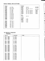
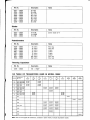
13.2 Electrical Components
Transistors
Ref. No.
Q101 Q102 Q103 Q104 -
3000x
3000x
3000x
3000x
BC
BC
BC
BC
1498
1498
1498
1478
Q201 Q202 Q203 Q204 -
3000x
3000x
3000x
3000x
BC
BC
BC
BC
1498
1498
1498
1478
Q301 Q302 Q303 Q304 0305 Q306 0307 0308 Q309 -
3000x
3000x
3000x
3000x
3000x
3000x
3000x
3000x
3000x
BC
BC
BC
BC
BC
BC
BC
BC
BC
1€A
1484
1078
1478
1498
1498
1478
1484
1078
Q401 Q402 Q403 Q404 Q405 Q406 Q407 Q408 Q409 -
3000x
3000x
3000x
3000x
3000x
3000x
3000x
3000x
3000x
BC
BC
BC
BC
BC
BC
BC
BC
BC
1484
1484
1078
1478
1498
1498
1478
148A
1078
Trl
E
14
Nr
Ret. No.
Q501Q502Q503Q504Q505Q506Q507Q508-
Descriptlon
3000x
3000x
3000x
3000x
3000x
3000x
3000x
3000x
Notes
2N 4921
2N 4918
BC 1478
BC 1478
BC 1478
BC 1478
BC 1078
2N 4919
Diodes
Ref. No.
Descriptlon
Notes
D502- 3000x
D503- 3000x
D504- 3000x
1N 4148
1N 52548
1N 4148
Zener diode 27 Y
Description
Notes
10
10
10
10
10
10
250
250
P os. l og.
P os. l og.
Li near
Li near
Li near
Li near
Pos. log.
P os. l og.
Potentiometers
Ref. No.
R108R208R333R351R€3 R451R501R502-
3000x
3000x
3000X
3000X
3000x
3000X
3000x
3000x
kohm
kohm
kohm
kohm
kohm
kohm
kohm
kohm
TrimmingCapacitors
14.0 TABLE OF TRANSISTORSUSED IN MODEL 3OOOX
E
E
T RA NSISTOR
RE F. NO.
Q1 0 1,Q102,Q103.
B
L
Q201.Q202,Q203
Q405, Q406
R
0305, 0306,
L
Q'104,0404, Q407
/C\
EE:JC
/6\
(
otB
\e_/
/o\
(
ltB
\e-l
E
/;\
€E::l'
c
BC149B
BC149C
BC209B
BC209C
BC149B
BC149C
BC209B
BC209C
Q403, Q409
Q401,Q402,Q408
Q301,Q302,O30E
BC 107B
BC 107C
A"
\9/
/G\
€ l - !- tc
E C8
u
CB
l-
1:-
c
BC207B
BC207C
BC208B
BC 148B
R C 1 'A'
Q501
2N4921
Q502
2N4918
Q503
BC147B
BC147C
BC 107B
BC 107C
BC207B
BC207C
Q504, Qs05
BC147B
BC 147C
BCl 078
BC107C
BC207B
BC207C
Q506
BC 147B
BC 147C
BC 107B
BC l 07C
BC207B
BC207C
Q507
E
BCl 078
BC 107C
Q303, Q309
R
t
\-9-l
c
8C1478
BC147C
Q204, Q304, Q307
?G-\ol B
2N4919
BC 107B
BC 107C
o508
Note:Two or more types of transistors,located in same frame, indicate equivalenttypes.
2N4919
;;
15.0 BLOCK DIAGRAM FOR MODEL 3OOOX
SWITC}I€SSHOWNIN UNOP€UTED
POStTtON_
RECORO
L BUTTON:So ANo Sb
RE@RO R BUfrON: 5c AND 5d
SOUNDON SOUNO
AND ECHO SELECTOR
{L INB HI G H R
IRADIO
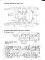
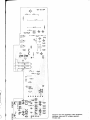
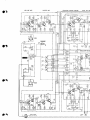
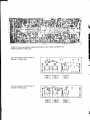
16.0 PRINTEDWIRING BOARDS AND CIRCUIT DIAGRAMS
16.1 European Version
J'
Jq
JJ
aaaaa
rfn-ifr--C=rrtEr
In p u t a n d o u tp u t
te rmi n a l b o a rd .
P ri n te d s i d e .
Board for record/playbackequalizing
am plif ier s ,lev e l i n d i c a to r a m p l i fi e rs
and booster amplifiers.
P r int ed s ide.
'-
(t,'
b-n
x-
x-
r"l:l
5'
JI
@
;-fRTlr r{-RT}
'{ t-{
\Oe
fl :T ti,t r---r r---'!
[r.i']
[r],fr_ l{rf{
I
rA'e5.*
'';''ir1'*'""6='
fiHtr#={g$+g1T;t6;i#":
";ff*ffi
f,#ffid&-#t
=,gl?:,3i
@@fl@'iffira,-+
f;
--H
tPu-;EE
I
[-.s gep"gs:fi
@-#[ffi*,'+ H,
B Bffiru.*{fl 'f,
-,e,,f,*'?md"b
T
," .'l'
]f-------1
|
lF-----r
."f l
F------1 |
lof
-l
#l
-l
l *l
#l
-l
|"*
T
,/ll
UternrA[O
r tgtg.rqr
o.0r o10?
F-l
I '1'
t_
'"""11
3]i
l-"n
\ *-=-t;--=-----=-.F\-ftLj
, ^7a\ aA. aAUa* . Aailb d u \ i o t n ? b e S d u A
\,/1l
Ol
tvz-l
.
rt
-/
./
[O
\
""""|i
l- '",
t' .
3\tL
,,,*t,
:___: : ,? U
f@h rEilrh-fl-
('67
'1i'\'fuu'fuu,
'jilt"
O]
,/
|
,irH)es
r'
r
o ooo@
I
r (ial;;ni:
-rr
,\'
, r ""t ' lf *
4l- *
:
FS5!+
?
lg
+-------{Fr!!r+
T
o 50l
e--r<-<
r*-5
. * ' t 6l?"56,i'1 ? '
{}d h d q
L@H
L{iEmr L@gP
:3
*--tlig-
P
H
,f,.
t.Ltt
Lt6t-P
"
--ElF-<
Jffir}.
L-',
-ffi""Y'".r,
?
F*
^.1
-"st
g
*" W
.+d
c5o?
I
t?t
:Pg
6i
l8t
lllr .'l
|
|
|
U-IrJ;
L{rsr]r
ll-G
a
{ffirP
Ht
r5-l
l!l
dh
r@P
E
c5o!
&
I
.5f
.l r.
-'
IEI
l)r
a:ffi59
a'rgg =auji-o
-ju5>a
a
}]h
.+.
"!d['
oigt
c50t
.tl-"
as
rl|r
FJ
Nl-..
c?!t
c92
c5s
.{b
6
taaalaaaa
a
a
a
!
.
r
I
ara
.
. [ *. .
a
a
a
.
qFf
Gt
.a
r{FstP
+o!?|{,<
.Eil!}|-<
d
h
LGS6tFr
..,<
ots
PI!!!9F
O$
OB
.tjg.gF
.llli
c16
p
qt
q
e26
LIE!!!!F
@l:
-l
ta
llF
q
tJF
I
ta
ll
lj
6666d
t*
$
s
-4.
i5a4o
{hc&
.@
la-
f
T rtE&l-h
leF
l .{!trh
a{
?
c ro5
O{F.
'tll
!
*'*it_.
d02
0i02
@
@
oo
r
rlr.-^-.d
LttqJ
.!jL
ffllrh
lffi"F
|>r
iFtJ
ffi,n
*tF<
-lF
@
ftd
^19[.
:a6
.191"
V
nh
qFTTP
Gt
ra
LCEP
qD2
ffi a&
c2o2 r-tth
ftd"v {qEmr
} } lh cAr V
q0
'.
.E!Ih
t-r
.Jh
:if'
dl-.
o999qO " " '
-q. ,#t
a1-
ra ;l
L@'P
c@
"l9t
;t
rr
LfFEfrJ
aa .t
L@J
aa
]l
L{EEIJ
,>
qn6JJ
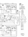
Boardfor mic./lireamplifiers,bufferamplifiers'
oscillator,bias and DC voltageregulator.
Printedside.
6
C
Boardfor mic./lireamplifiers,bufferamplifiers'
oscillator,bias and DC voltageregulator'
Printedside.
'[
o)
M IC,/L INEAM P
BUFFERA MP
E QU A LIZE DR E C OR DP R EA MP
LE V E L IN D A MP
I
I
I
I c ar o
t"'
I
I cros
2l
Qa0{
8Clal
c4l3!
0,022!-l-
I
!C415
i-
l-q0?2)
1r--{jEL 42"''
c4 l 6 r r
0 ,0 1 !
ilc4t7
0,01!
Li 3
OD
RECORD
HEAO
L
8 5 ,5kH z
LEVE
tNo
E
oq
REC/LEVEL
o301
8Cr47
c309
?N
- 1c201
_
70
Q 204
8C r478
0,022!
-r -r -l- 0,022,
,'
l :-'l
I
tt'
I f---f l-et- -7
tv
6
c3 r7
00r.!
I
tq
|
$UND ON $NO
AND ECHO SELECTOR
AMP
BOOSTER
EQUALIZEDPLAYB AMP
r{oTEs
S[!
MTN
EE
\ 7,
=
"oono
= TOPPUTE MffiKING
= REARPANELsRXrNG
ii€:F:il
FREOAOJ = PRESETCONrRol
= rEsT PorNT
/?\ A,
ffifi
= CONECIONTERMINAI
= UPPERTRACX: LEFTCHANNEL
TRACK.RIOHTCHNET
- LOWER
. SIoNALPATH.PLAVBACX
= SIGNALPATH,RECORO
= oErcSllEO CAREoNR€SISTOS
a
CAPASITORS
INDCATED
IN pF UNLESS
OTHERWISE
SPECIFIEo., ' 1000mpF
IN OtMS UNLESSOII{RW6E
RESENRS INOICATEO
SECIFIEO k . 1000oHMS M ' 1m0000oHMS
VOTIAO€sGIVENIN PARANTHESIS
REftR IO R€CM
POSrIlOfl
RECORD
A21
L
R
Q405
BC 1 1 9 B
(nrP ql rP 25
cU tlr d b
oo
TI
IP $rP
dD
db
ao
fP
ilB ct
o@
oo
R IGAI
IE VE L
IND
TEFI
ARE sffi
IN
SI'CHES
T'iIOPERATEO POSITIOII
P I L OT
E
z3/t
\1 r ^
'" -
i , 5k Hz
21
20
l9
t8
17
DC VOLTAGE REGULATOR
-
-l
6
S1 0 l 5102 541
a |^
/ ^ "'
EOU AL IATION
I
,aI
a5G
?N 4919
Q
^
s So rs 3 o 2s l o 3
SWITC H
860
c8m
SI
llcl
]
@
99
ft
?30v
5O Bu
@
IR AN SFOR M ER
I
a
AN O M OT OR CONNECT IONS
SEN ITIVIIY
AT 1 0 0 H 2
2
6
Lt
B
II
l2
Iqndb.rg! RadiolqFakkA/S
WIRING OIAGRAM FOR
TAPE RECORDER SERTES 3p00x
MIC: DIN
D R A WTN G
N O.158 00-2
r1- 1t'69 AO.
'\-i,-llY^?*
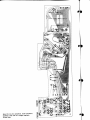
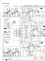
16.2 U.S. Version
E OU A LIZE DR E C IR D P R E A MP
EUFFER AMP
MIC,/LINE AMP
I
I
I
1.
| !1'd
t'"v
I
I cl os
I
LE V E L IN D A MP
o1o3
tt'ott
AOJ L
"Ea/aaue
i ;\
2l
t
C a t3 !
f
!C 4 1 5
o,oxl T T
Tqcrr,
.lf---.{;EL< op srcr
35
_--,|
liml
i
rE
^t' R
L13
-
t8
R EC OR O
H EAO
L
-55
tEvFLr
rNo l/
G]\
TOR 85,5 kH z
StAS
HEAO
L
€RASE
EAD
t
ERASE
EAO
atas
HEAO
e
L EV€L
IN D
@
8 C r 0 7 B R EC /L EEL
AOJ R
o301
acl478
0O22t-f -f -T- 0,022r
,,
I i - 'l
l
ll."......-f 3$uo "2 smt
$Lt{D oN sotxo
ATO ECrc S€LECIOR
@
r€l Es
BOOSTER
PLAYB AMP
$@ l .eoo" o
@
. tOPPUTEMARXING
f,ffig
: REARPAilELstrrs
l$tr$
FREOADJ . PRESET
CoNTRo!
. TEsTPorNT
O l-f''
c.3r + I
-r
'00y t- I
r00r
T
O2 L
,rFu
BCr47A
r? !
o105
8C119B
l ,_.
i!1,
""t
c 130
18V -- 0P68!
----]ir
.l' -
)
L
R
:
.
Fr
C ON EC IION T€ R M IXAL
U PPER TR AC X: L EFI C H AN N EL
= L OWER TR AC K: R IGH T C H AI€ L
. SION AL PATh , PTAYAAC K
SIGN AL PAIH . R € C OR D
a
cARaoN RES|SrORS
' 0€P0srIE0
C APASITOR S IN OIC ATEO IN PF U IESS O'IH ER WISE
l0000mpF
SPEC l Fl Eo ,r r .
I ca29|
I r00! |
R ESISTOR S IN D IC AIEO IN OtM S U N L C SS OTI* R WSE
k . r0m oHMs
il . lmo 000 oHMs
sp EctFr Eo
VOLIAGES GIVEN IN PARANTH€SIS REER TO RECOFD
POStTtON
RECORD
qtP
flrP
ob
db
oo
oo
oo
oo
P
Tl -P qr
ob
T
I P cl
fP
d@
d@
oo
23
z2
zl
20
19
r6
t?
RIOHT LEFT
lN
srrcH€s aR€ sff
UrcPERAIEDPOSIIIfr
PlLOI
33/t
s(or s402 sls
,1t- o
''o' ^
/ ^.t/^
slor slo2 s3o3
"'
d
SWITCH
EOUALTZAII0N
---l
DC VOLTAGEREGULATOR
o50
2N49r9
I
=
c5r2 I
lc5B
lc5r{
t10v 50H:
I
r o o o r l 1 0 .,, lo ,' r
@
7--7 @l
99
TR AN SFOR H ER AN O M OTOR C ON N EC IION S
ft
115V
50H?
a)
6
@
sENrTrvtl
AT 100Hr
2,2
D
I
I
I
Iondb.rgs Rod,otobrrklA/S
WIRINO OIAORAM FOR
YAPE RECORD€R S€RIES 3OOO)(
MIC: JACI(
N 0.l 58l l -3
D R A WTN G
ll-t2-69 GS.
16-1-70 te
?;i:i39fr
\
\
Y-l
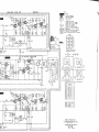
Board for record and playback equalizingamplifiers,level indicator amplifiersand
booster amplifiers.Printed side.
Input and output terminal board for
channel L. Printed side.
ffi
+
lLowtNl
rx-iol-ir.r-'!
lofiFrfrr
Lr.:t--i L+e'r-.i
Lrqlr--.i
L'eCi
ilrdtl
!-ou-rpuT
I
Llr9rl]-i
I nput and ou tp u t te rm i n a l b o a rd fo r
channel R. Printed side.
(
-
-
-
t
I
-
T a ndber gs Radiofabr ikk A/S, Kjelsas.
TANDBERGS
T andber gs R adi ofabr i k k A/S, di v . Kj el l er
RADIOFABRIKK
P.O.B. 9, Korsvoll, Oslo 8, Norway
A/S
r?