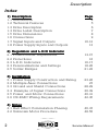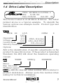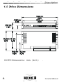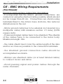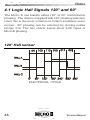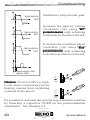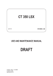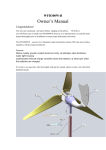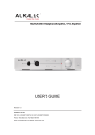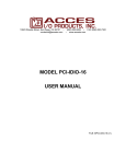
1
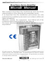
Brushless Servo Amplifier
MicroB Manual
This manual describes the mechanical and electrical
characteristics of the MicroB servoamplifier series.
It is important that the installation procedures are only
performed by qualified personnel in accordance with local
safety guidelines.
Whoever installs the equipment must follow all of the
technical instructions printed in this manual.
For more information, please contact AXOR's technical
department.
All rights reserved. Reproduction in whole or in part is prohibited without prior
written consent of the copyright owner. All specifications are subject to change
without prior written consent of the copyright owner. All specifications are subject
to change without notification.
Service Manual
Ver. MCB-gb 24-07-2002
1
Chapter 1
Description
Index
1) Description
1.1 Introduction
1.2 Technical Features
1.3 Drive Description
1.4 Drive Label Description
1.5 Drive Dimensions
1.6 Connections
1.7 Signal Inputs and Outputs
1.8 Power Supply Inputs and Outputs
Page
4
5
6
7
8
9
10-12
13
2) Regulation and L.E.D Indicator
2.1 Potentiometer Adjustments
2.2 Protections
2.3 L.E.D. Indicators
2.4 Personalizations and Settings
2.5 Solder Bridges
14-15
16
16-17
18-20
21-22
3) Installation
3.1 Power Supply Construction and Rating
3.2 Multiple Axes Connections
3.3 Ground and Shield Connections
3.4 Example of Signal Connections
3.5 Power and Motor Connections
3.6 CE-EMC Wiring Requirements
23-26
27
28-29
30-39
40-41
42-45
4) Notes
4.1 Hall Effect Commutation Phasing
4.2 Unknown Motor Procedure
46-47
48-50
2
Service Manual
Chapter 1
Description
5) Adjustments
5.1 Speed Adjustment with Encoder Feedback
5.2 Armature Speed Feedback Adjustment
5.3 Hall Effect Sensor Speed Adjustment
5.4 Adjusting Speed Balance
5.5 Nominal Current Adjustment
5.6 Peak Current Adjustment
5.7 Ramp Time Adjustment
5.8 Dynamic Constant Adjustment
Page
51-52
53
55
56
57
57
58
59-60
6) Troubleshooting
6.1 Troubleshooting
61
CE Conformity Declaration
62
Service Manual
3
Chapter 1
Description
1.1 Introduction
The Micro B Brushless Servo Amplifier is a compact
full four quadrant drive. The (MOSFET)output power
stage is controlled by a 22 Khz PWM (Pulse Width
Modulation)signal that allows it to drive small to
medium sized brushless servo motors where high
dynamic performance and precise speed is required.
The Micro B only requires a single power supply to
operate and develops all needed voltages on board to
make power supply design easy and convenient.The
imput voltage is from 20 to 80 Vdc max; Chapter 3
describes how to design a proper supply.
Closing the velocity feedback loop to motor may be
done in several different ways to accommodate most
applications. Three types of velocity feedback are
available with these drives. Refer to Chapter 5 for the
setup procedures that will effect your application.
Feedback Types:
-Hall effect + encoder.
-Internal PWM (Armature).
-Hall effect
These drives have been factory set, but these settings
may need to be changed based on the motor and the
load,refer to Chapters 2 and 5 for the correct setting
for your applications. Changes are made using
resistors, potentiometers and solder bridges.
4
Service Manual
Description
Chapter 1
The nominal and peak current settings are adjusted
by adding resistors to the area provided on the drive.
This is done by removing the cover and referring to
Chapter 5.5 and 5.6 to select the correct values and
placement on the drive's PCB (Printed Circuit Board).
The drive dimensions are 5.33"x3.22"x 1.12".The MicroB
is avaible in 4 nominal power versions, listed below.
2,5-5A 5-10A
8-16A 10-20A
The operating temperature is from 32° to 104°F( 0 to +40
°C) and no ventilating system is required as long as the
spacing between the drives allow for adequate air flow.
1.2 Technical Features
Input Range
PWM frequency
Operating Temperature
Storage Temperature
Drift
Analog input (Velocity)
Current monitor
On board Power Supplies:
Encoder and Hall Effect
Auxilary power supply
Max. Encoder frequency
Band Width
Humidity
Weight
Altitude
Service Manual
20-80 Vdc
22 Khz
32°-104°F (0°-40°C)
14°-158°F (-10°-70°C)
+/-10uV/Degree F
+/-10 Vdc
+/-7 Vdc=Pk. curr.
+5 Vdc (130 mA Max)
+/-10 Vdc (4 mA Max)
250 Khz Max
2.5 Khz
10/95% non-condensing
10.6 oz (350gr.)
6500 Ft. (2000m.slm)
5
Chapter 1
Description
1.3 Drive Description
1
2
3
4
5
6
7
8
6
Calibration Pads
Calibration Potentiometers
Quick Disconnect Signal Terminal Block
Quick Disconnect Power Terminal Block
Fixing Screws
Product Cover
Product ID Label
Serial Number
Service Manual
Description
Chapter 1
1.4 Drive Label Description
TYPE MCB060-5/10-PWM- 0
ADJ
5/10A RA
Date 27/04/98
Ord.365 /98
The Product Label is on all Micro B Drives. The Label
printed above is a typical example. To identify the
various options see example below: Product type and
Identification.
TYPE
MCB
60
2,5/5
2,5/5
5/10
8/16
10/20
Operating
voltage
I nom/I Peak
Velocity Feedback
Options
PWM
ARM=Armature
HAL=Hall Effect
00E=Encoder
0
1
2
3
4
ADJ is the identification of specific adjustments on the
product for specific motors. If the product is furnished
Standard, the ADJ will show the maximum operating
current.
ADJ
T29XX
1000I/g
3000RPM
Motor
Imp. Encoder
Nominal speed
ORD is AXOR's internal order number which relates to
product distribution. Always quote this number when
asking for technical assistance.
Service Manual
7
Description
Chapter 1
1.5 Drive Dimensions
NOTE:Dimensions mm- (Inch)
8
.
Service Manual
Chapter 1
Description
1.6 Connections
M
Service Manual
9
Description
Chapter 1
1.7 Signal inputs and outputs
Signal Connector Description.
1
IMOT (OUT) Current Monitor, Range: +/-7
Vdc Output in Volts, the current
in the motor windings.Since
cur rent is propor tional to
torque, this output may be used
to monitor the torque the motor
is producing.
(+/-3.5 Vdc=nominal current,
+/-7Vdc=Peak current)
2
OK (OUT)
Drive OK, Open Collector
output
50mA
24Vdc
Max.(Normally closed, opens
when in protection mode)
3
TPRC (IN)
(OUT)
This signal can be used in 2
distinct modes:
A. Motor Current Limit mode;
Connect an external resistor to
GND (pin 4) reduces the
maximum cur rent.
A 47K
resistor reduces the current by
50%. Note: the drive velocity
loop remains active.
B. Current Reference (Torque
amp mode Input): Range: +/10V which corresponds to the
drives peak current output.
10
Service Manual
Chapter 1
Description
Signal inputs and outputs (Continued)
Continued:
In this mode the velocity loop is
automatically disabled.
The TPRC terminal can be used
(in modes A and B as a drive's
current.
** Use an instrument with an
input impedience greater than
100Kohm.
Drive
Common
Ground.
Corrisponds to power supply's negative -AT input.
4
GND
5
+10V (OUT) Power Supply +10Vdc 4mA Max.
6
-10V (OUT) Power Supply -10Vdc 4mA Max.
7
ENABLE(IN) Drive Enable. (Range +8Vdc to
+24Vdc).
It's also possible to enable the
drive with a low signal by
connecting a GND input (to
enable such a function, close
solder bridges S12-S13).
Continued
Service Manual
11
Description
Chapter 1
Signal inputs and outputs (Continued)
8
+REF (IN)
9
-REF
(IN). Reference Negative differential
input. (Velocity command)
10
CHA
(IN)
Encoder input Channel A
High logic level > From +3,2V to
+24Vdc.
Low logic level < From +0V to
+1,5Vdc.
11
CHB
(IN)
Encoder input Channel B.
High logic level > From +3,2V to
24Vdc.
Low logic level < From 0V to
1.5Vdc.
12
+V (OUT).
Power Supply +5V ( 130mA Max)
Option: +V = +12V.
13
GND.
Drive Common Zero Signal.
Corresponds to power supply's
negative -AT input.
14-15-16
12
Reference Positive differential
input. (Velocity command)
HALL A-B-C (IN).
Hall Sensor inputs from the
motor. Each input has a pull-up
resistor of 1 Kohm to + 5Vdc.
High logic level>3,2V , Low logic
level<1,5V.
Service Manual
Description
Chapter 1
NOTE !:
You may power the motor's hall sensors
using the auxilar y power supply
generated by the MicroB (Terminal 12
+V).
If an external power supply is used,
open solder bridge S11.
Such an external power supply, if used
to supply the hall effect sensors, must
be applied to the motor at the same time
the MICROB is switched on.
1.8 Power Supply Inputs and Outputs
+A
T
+AT
(Input).
Positive continuous power
supply. (range between +20V
Min. to +80V Max).
- AT
(Input).
Negative continuous power
supply. Common Zero Signal
GND.
U
(Output).
Motor Connection U Phase
V
(Output).
Motor Connection V Phase
W
(Output).
Motor Connection W Phase
Service Manual
13
Adjustments
Chapter 2
2.1 Potentiometer Adjustments
VEL
Motor speed adjustement.
Use this potentiometer to
adjust the maximum motor
speed. Turn clockwise (cw)
to increase the motor speed
and counter-clockwise (ccw)
to reduce the motor speed.
The range of the adjustment
is +/-20%.
Note:
Potentiometer is
disabled in torque amp mode.
BIL
KV
Offset adjustment.Adjust this
potentiometer to cancel any
motor speed when the Ref.
input is 0 Vdc.
(Max ref. compensation +/200mV).
Gain potentiometer.Use this potentiometer to increase
or decrease the dynamic behavior of the motor
With a clockwise turn (cw)we increase the gain of the
PI “speed stage”, therefore, improving the response.
Note: P
otentiometer is disabled in tor
que amp mode.
Potentiometer
torque
DER
Derivative potentiometer. Turning this potentiometer
clockwise decreases motor overshoot.
Note: P
otentiometer is disabled in tor
que amp mode.
Potentiometer
torque
14
Service Manual
Chapter 2
Adjustments
Potentiometer Adjustments (continued)
ACC
The solder bridges S1-S3 select the acc/dec function
(ramp). With this potentiometer we can adjust the slope
of the acceleration and deceleration ramps. Turning
the
potentiometer clockwise (cw) increases the
ramp time from 0,1 to 1 Sec. (with 10 V reference).
It is also possible to increase or decrease the pre-set
max acc/dec ramp by opening solder bridge S2 and
inserting resistance RAMP.
(See chapter 5.7 RAMP TIME ADJUSTMENT)
Service Manual
15
Chapter 2
Adjustments
2.2 Protections
The Micro B is equipped with protection circuits to
safeguard both the motor and the drive, in case of
malfunctions.
All faults are indicated by LEDs on the front of the drive.
(See the next page).
The two types of interventions are Reversible and
Irreversible. There are two types of faults:
----Reversible Protection Intervention:
The drive is automatically reset/restarted when the cause of intervention has been corrected.
-Over Current limitation
-Over/under voltage input
----Irreversible Protection Intervention:
The drive is not reset/restarted. The power supply must
be removed and the cause of intervention eliminated, then
the power supply can be replaced. *Note: A mininum
amount of time must pass in order to ensure that the drive
is completely off prior to replacing the power supply.
-Short circuit
-Over temperature
-Missing Hall Signals
-Improper Hall Commutation
2.3 L.E.D. Indicators
Five LEDs are located just in front of the potentiometers
and show the current state of the drive.
16
Service Manual
Chapter 2
Adjustments
L.E.D. Indicators (Continued)
-OK (GREEN) Normally ON. This
indicator shows that the drive is
operating correctly. If this LED is Off, it
is indicating at least one fault has been
activated. The faults that affect this LED
are:
--Over/Under inputvoltage, Over 80Vdc
or under 20Vdc.
--Over temperature, Over 104°F (40°C).
--Short Circuit, Outputs shorted to each
other or to ground.
- IN (RED) Normally OFF.
This indicator is lit if the drive is in Over
current mode.
- ST (RED) Normally OFF. This indicator is lit when
the drives internal temperature reaches 104°F (40°C).
Remove power and wait for the drive to cool before reapplying power. If operating temperatures are close to the
Max operating temperature of the drive, a fan, heat sink or
air conditioner may be needed to remedy the problem.
- OC (RED) Normally OFF. This indicator is lit if there
is a short circuit between the motor leads and/or ground.
Remove power and examine the motor connecting leads
for shorts before re-powering the drive.
- AH (RED) Normally OFF. If lit it represents either
missing Hall signals or incorrect 60° or 120° settings.
The drive is factory set for 120°.Have a qualified technician
check the Hall Effect signals with a voltmeter or an
oscilloscope.
This fault is a latching fault. Refer to Chapter 2.5 for correct
procedure on changing this function.
Service Manual
17
Adjustments
Chapter 2
2.4 Personalizations and Settings
If the drive isn’t set up for the servomotor, follow these
procedures. If changes need to be made to internal drive
settings, please wait for at least 10 seconds after the power
has been removed and the OK LED is off.
All of the personalizations are located inside of the Micro B.
To gain access to the adjustment pads and the solder bridges,
unscrew (A) , and remove the cover (B). (See figure below).
A
A
B
18
Service Manual
Chapter 2
Adjustments
Personalizations and Settings (continued)
All of the adjustments are located in the area behind
the potentiometers . The resistors mount on headers
spaced at 0.4" (10.16mm) pitch and the capacitors
mount on headers spaced a 0.2" (5.08mm) pitch.
Use 1/8 or 1/4 watt resistors and radial lead capacitors.
RENC
Encoder or Hall Effect resistor;
Chapter 5.1
RA
Armature Feedback resistor;
Chapter 5.2
RCA
Droop compensation for internal
motor resistance (RI);Chapter 5.2
RIN
Nominal drive current resistor;
Chapter 5.5
RIP
Peak drive cur rent
Chapter 5.6
GAIN
Changes static gain in the velocity
loop. Open Solder bridge S6 and
inser t R GAIN if a change is
required. Consult factory for the
correct value.
resistor ;
Continued
Service Manual
19
Chapter 2
Adjustments
Personalizations and Settings (continued)
CDER
Derivative constant capacitor, increases
the velocity loop derivative constant.
Consult factory for the correct value.
RKV- CKV
Resistor and capacitor values that
respectively for m the propor tional/
integral network of the velocity loop
gain. These are disabled by opening
solder bridge S5.
RKI- CKI
Resistor and capacitor values that
respectively for m the propor tional/
integral network of the current loop gain.
These are disabled by opening solder
bridge S7. For more information see
chapter 2.5, 3.5.
20
Service Manual
Chapter 2
Adjustments
2.5 Solder Bridges
13 Solder Bridges located on the left hand side of the
drive are used to change internal and external functions
on the MicroB. Below are the descriptions of the solder
bridge functions.
The drive is factory set with the following Solder Bridges
and their function:
S1 and S3 Normally open. (See section 5.7 “Ramp Time
Adjustment”).
S2 Normally closed. (See section 5.7 “Ramp Time
Adjustment”).
S4 Normally closed. If Open - disables the Encoder and
Hall Effect velocity feedback.
S5 Normally closed. If Open, install components for the
Dynamic velocity costant CKV and RKV. Consult factory for
proper use.
S6 Normally closed. If Open, insert the GAIN resistor.
(Static Gain). Standard value= 22ohm.
Continued
Service Manual
21
Chapter 2
Adjustments
Solder Bridges (continued)
S7 Normally closed. If open ,install components for the
Dynamic current constant CKI, RKI. (Standard constant
RKI=220 Kohm , CKI= 2,2nF).
(Adjustments Reserved for Qualified Personnel Only!)
S8 Normally open. If closed, when the IN protection
operates the green OK LED goes off.
S9 Nor mally closed. If open ,disables Encoder
feedback and enables Hall feedback. See section 5.3 .
S10 Normally open. (120°Hall Commutation). Close to
select 60° Hall Commutation. See section 4.1 .
S11 Normally closed. If open, the alarm protection for
missing Hall Effect Signals will not disable the drive.
S12 - S13 Normally open. Drive Enable logic high (+8/
+24Vdc). Close for Drive Enable logic low <=6V.
See page 33 for additional information.
22
Service Manual
Installation
Chapter 3
3.1 Power Supply Construction and
Rating WARNING:Use only Un-regulated power
supplies with the MicroB Drive.The power
supply is used to absorb the motor's BEMF.
Also, with this scheme, no braking resistor is
generally needed.
The MicroB was designed to generate all required supply
voltages in the Drive, so only a simple single voltage power
supply is needed. Use the schematic and formulas
provided below to design a supply a suitable drive power
supply.
AC
Power
Transformer: A single ground is used in the drive
connected to -AT, so DO NOT USE AN AUTO
TRANSFORMER . Use a standard heavy duty power
transformer as shown in the schematic above. The VA
rating should be 10% greater than the power needed by
the system to insure cool operation. DO NOT CONNECT
ANY TRASFORMER PRIMARY, OR SECONDARY SIGNALS
TO GROUND.
Keep the +AT and -AT wires between the power supply
and the MicroB as short as possible.
Voltage: The primary voltage depends on what is
available locally for a single phase. The secondary voltage
is calculated from the motor’s voltage at the required
operating speed.
The secondary voltage V2 is:
V2(dc) = Vmotor
0,8
Service Manual
23
Installation
Chapter 3
Power Supply Construction and Rating
(continued)
Where:
VM = E+ (Ri x Im)
E = Ke x n°
1000
VM=Motor voltage(V)
E =motor BEMF(V)
Im = I motor (A)
Ri =Winding resistance (Ohm)
Ke =Voltage constant (V/kRPM)
n° = Max. speed(RPM)
Considering you must keep a certain margin during the
motor's breaking phase, you should never exceed a
voltage of 60Vdc (44 Vac from transformer).
The max. value is 80Vdc and the min. value is 20Vdc.
Example:Brushless DC Motor with the following data:
Im =3,8 (A)
Ri = 2,5 (Ohm)
Ke =12 (V/kRPM)
n° = 3000(RPM)
E = 12 x 3000 = 36 (V)
1000
VM = 36 + ( 2,5 x 3,8 ) = 45 (V)
V2 = 45 = 56 (V)
0,8
V1= 56 = 39,8 (Vac)
1,41
You'll use a transformer with the secondary V1= 39
Vac, 44Vac is OK.
24
Service Manual
Installation
Chapter 3
Power Supply Construction and Rating
(continued)
The transformer's nominal power is calculated based
upon adding all the motor powers together that will be
driven by the transformer.
Where:
VA= Motor power 1 + motor
power 2 + ...etc.
Note; In multi-axis applications, the transformer's power
can be downgraded by 30%.
Capacitor
The working voltage of the filter capacitor should be at
least 20% greater than the supplies output voltage (V2).
The filter capacitor is calculated by the formula below.
C (uF) = (VA) trasfo. x 1000
V2
V2 = No-load supply output condition.
The filter capacitor is used to filter the rectified voltage
to less than 10% ripple and absorb the BEMF from the
motors when they are braking.
Bleeder resistor
The bleeder resistor is used to drain the charge from
the filter capacitor when power is removed from the
supply. This helps in bringing the supply voltage down
quickly. This resistor is mounted directly across the
filter capacitor. To calculate the correct value and
wattage use the formula below.
RS (Ohm) = 20.000.000
C (uF)
P (W
atts) = V22
(Watts)
RS
Where : RS= Bleeder resistor value and P= Resistor
Wattage
Service Manual
25
Installation
Chapter 3
Power Supply Construction and Rating
(continued)
Fuses
Fuses are required on both the primary and secondary
of the transformer to protect against harm to the system
and the transformer itself. They need to be of the slow
blow type to handle current in-rush at power-up. Locate
the primary fuse (F1) on the hot leg of the AC input
power and the secondary fuse (F2) on the + side of
the secondary output, before the rectifier. Use the formula below to calculate the correct values for both
fuses.
Where:
F 1 = (VA) transformer
x
Vac (primary) ac
F2
X MCB
X MCB
X MCB
X MCB
2,5/5
5/10
8/16
10/20
1.1
=3,16 A
=5 A
=10 A
=20 A
A separate fuse F2 is required for each drive in a multiaxis system.
26
Service Manual
Installation
Chapter 3
3.2 Multiple Axes Connections
In case of connecting more than one axis to a single
supply, always connect each drive DIRECTLY to the
supply and keep the wires as short as possible, twist
the + and - leads together as twisted pairs. (Try not to
exceed 1,5 feet (0.5m) in length.
Incorrect W
iring T
echnique.
Wiring
Technique.
Power Supply
MicroB
+AT
+AT
+AT
- AT
- AT
- AT
Use this.
-Vdc
Power Supply
MicroB
+AT
+AT
+AT
- AT
- AT
- AT
Service Manual
+Vdc
+Vdc
-Vdc
27
Chapter 3
Installation
3.3 Ground and Shield Connections
28
Service Manual
Chapter 3
Installation
It is important that the drive's ground connections are as
short as possible and no longer than 20 cm. The figure
shows the connection using terminals fixed to the drive's
base (bottom). This connection also reduces disturbances
in the net.
The Motor ground cable has to be external (not inserted in
a multipolar cable) with minimun section 1.5 mmq (0,059
square inch).
Drive power and signal cables must be shielded. The cable
shields must be connected to the body of the motor.
Shielded cable is not required for the motor power cable,
the UVW cables should be twisted together.
Service Manual
29
Chapter 3
Installation
3.4 Examples of Signal Connections
The following design shows an application utilizing a
differential reference from a C.N.C. .
The drive is enabled using the Auxilary power supply
+10V (Connector 5). It is possible to use an external
power supply for this function (24V DC).
It's also possible to Enable the drive using negative
logic.(See page 33).
On connector 2 "OK" an exter nal relay coil was
connected. This output has a max. rating of 50mA at
24Vdc. Connect the power supply GND externally
using connector 4.
30
Service Manual
Chapter 3
Installation
Examples of Signal Connections
(continued)
The following design shows an application using speed
reference connections in the Common Mode.
The following figure shows an application with speed
reference connections using an internal Micro B power
supply.
The
speed
potentiometer
needs to be in the
range of :
>10Kohm and
<47Kohm.
Service Manual
31
Chapter 3
Installation
Connections for operating in Torque Amp
Mode (Current Mode)
With a voltage output (ex. from a CNC) you can command
the drive in torque mode. Applying a signal of +/- 10V at
TPRC causes the Micro B to supply positive or negative
peak current. Applying 5V gives you the nominal output
current. (See figure 1).
1
By connecting a resistive load at TPRC (ex. a
potentiometer), you can limit the output current. In this
configuration the internal velocity loop remains active.(See
figure 2).
2
Output current limit
potentiometer, 470K1M Ohm.
32
Service Manual
Chapter 3
Installation
Enabling drive with Positive Logic
To enable the drive with positive logic, ensure Solder
Bridges S12 and S13 are open. Vin >8V,<24Vdc.
Unconnected input
Input to +V
=Drive Not Enabled
=Drive Enabled
Enabling drive with Negative Logic
To enable the drive with negative logic ensure Solder
Bridges S12 and S13 are closed.
Vin < = 6Vdc.
Unconnected input
Input to GND
Service Manual
=Drive Not Enabled
=Drive Enabled
33
Chapter 3
Installation
Hall Sensor + Encoder Connections
The following design shows typical connections
between the drive and a brushless motor. In such a
configuration, Hall effect and Incremental type Encoder
A and B signals are used.
The Encoder and Hall Sensor power comes from the
(+V) connector 12 .
For speed adjustment in this configuration, see
page 51.
34 Continued
Service Manual
Chapter 3
Installation
Encoder Connection from External Power
Supply
The figure below shows a self-powered MICRO B with
Hall signals while the Encoder signals are powered
externally.
The Ground of the external power supply must be
connected to the drives GND.
For speed adjustment in this configuration see
page 51.
Continued
Service Manual
35
Chapter 3
Installation
Hall Sensor + Encoder Connections
(continued)
The Encoder input on the MicroB is for incremental
single ended, NPN or PUSH-PULL output type
encoders, it will also work with a differential output type.
Only connect the +A and +B outputs to the drive if
using a differential output type encoder.
The drive can supply voltage to the connector +V equal
to +5Vdc. (Preset in factory for +5Vdc ,+12Vdc optional).
The drive's (+5dc) supply is able to supply 130 mA for
the encoder and Hall effect sensors.
Care should be taken when using +V to supply the Hall
switches and the encoder. Measure the current draw,
it must not exceed the 130mA limit. If the current
exceeds 130mA, use the controllers +5Vdc output for
the encoder. Be sure to also connect the common
supply from the controller to the drive to complete the
circuit. If isolation is required between the drive and
controller, consult the fatcory for the correct wiring.
WARNING! If you insert a load resistor between
channel A and A neg. or between B and B neg. of the
Encoder Line Driver, the encoder supply current will
increase and the signal voltages will decrease, they
may not be large enough to commutate the drive
logic input A and B. (V High>3,2Vdc ,low< 1,5Vdc).
36
Service Manual
Chapter 3
Installation
Hall Sensor + Encoder Connections
(continued)
WARNING: Hall sensors are generally supplied
using the internal +V of the Microb (connector
12). If an external supply is used, open solder
bridge S11.
Encoder technical input data
Encoder input logic
Push-Pull ,Line-driver, NPN.
Input acceptance level
From 0 - 5Vdc to 0 - 24Vdc max.
Encoder max. frequency 250 Khz
Encoder power supply
+V= +5V @130 mA Max
Service Manual
37
Chapter 3
Installation
Hall Signal Connections (ONLY)
The following design shows connections to the drive
using Hall Effect Signals (only).
Such signals are used for processing current and for
motor speed regulation.
Motor speed regulation is inferior to Encoder + Hall
Effect feedback, but sufficient for many applications.
There are 2 possible velocity feedback options in this
configuration:
1) Armature velocity feedback or PWM.
2) Hall Effect velocity feedback.
38
Service Manual
Chapter 3
Installation
Hall Sensor Connections (ONLY) (cont'd)
Armature feedback gives good speed control and
acceptable torque at low velocity (>5 RPM). This method
considers that such a solution is sensitive to R x I dropping
inside the motor. This can be compensated, however, by
inserting a compensation resistor RCA.
For Speed Adjustment in this configuration see
pages 53 and 54.
If using Hall Effect feedback, speed control is good from
300 RPM up to max. velocity. The velocity doesn't drop due
to the motor's internal R.x.I..
For Speed Adjustment in this configuration see
page 55.
Service Manual
39
Chapter 3
Installation
3.5 Power and Motor Connections
Power cable specificationis recommended as follows:
1.5 square mm up to 8/16
2.5 square mm up to 10/20
The U V and W drive outputs can be connected directly to
the motor terminals.
The minimum motor inductance value is 0,8mH. Where
the motor armature inductance is less than 0,8mH, use 3
chokes connected in series with the motor.
The amplifier itself is capable of driving motors with
inductance between 0,8mH and 40mH.
40
Service Manual
Chapter 3
Installation
For some motors it may be necessary to alter the drive
current loop. This is done by opening solder bridge S7
and inserting a RKI resistor and a CkI capacitor in the
personalization zone.
Service Manual
41
Chapter 3
Installation
3.6 CE-EMC Wiring Requirements
42
Service Manual
Chapter 3
Installation
CE - EMC Wiring Requirements
(Continued)
The standard for electromagnetic compatibilty is
summarized in CEI EN 61800 (complete).
Micro B conformity is assured only if it is installed following
the precise assembly criteria expressed below. The
fundamental assembly requirements are summarized
below:
1)Use shielded cables, both for power connections to the
transformer and the motor, and for signal connections to
the controller.
2)Separate the power cables from the signal cables, if these
need to cross, cross at right angles.
3)Correctly ground all the points shown.
4) Use ferrite suppressors where shown.
NOTE:the MicroB drive
connections as shown on the
previous
page,
with
accessories, complies with
the EMC standard CE-EN
61800-3 norm.
Service Manual
43
Chapter 3
Installation
CE - EMC Wiring Requirements
(Continued)
Previous page picture connection description
--It is important that the drive's ground connections are
carried out using the shortest cable possible, which should
not be longer than 20 cm. Connections are shown using
terminals fixed to the drive's base (bottom), this reduces
disturbances in the net.
--Motor ground cable has to be external (not inserted in a
multipolar cable) with minimun section 1.5 mmq (0,059
square inch).
--Power and signal cables have to be shielded. The shields
of the cables have to be connected to the motor body.
Maximum length 15m.
--the cable shield must cover the entire length of the wire
and be as close as possible to the connection terminals.
--the shielded ground connection cable should be
accomplished as shown.
--Always use shielded cable (or at least twisted cable)
to connect motor and drive.
--Avoid passing signal and power cables through the
same channels.
44
Service Manual
Chapter 3
Installation
CE - EMC Wiring Requirements
(Continued)
Attenuation characteristics of the ferrite magnets indicated.
Type
:
FER RITE
Model :
Ferrishield CS28B 1984 or
Ferrishield SS28B 2032.
Service Manual
45
Notes
Chapter 4
4.1 Logic Hall Signals 120° and 60°
The Micro B can handle either 120° or 60° commutation
phasing. The drive is supplied with 120° phasing selected,
since this is the most common in today's brushless servo
motors. 60° phasing can be selected by closing solder
bridge S10. The two charts below show both types of
MicroB phasing.
120° Hall sensor
ELECTRICAL CYCLE
46
Service Manual
Notes
Chapter 4
60° Hall sensor
ELECTRICAL CYCLE
Signals produced by rotating the motor shaft clockwise.
Service Manual
47
Notes
Chapter 4
4.2 Unknown Motor Procedure.
A simple procedure to use if the motor is not
supplied by AXOR.
Since there is no unusual standard for brushless
servomotor manufactures and drive manufactures for
motor lead phasing a simple procedure is needed to
get the wiring correct. This procedure will help in
getting your motor wired correctly, if it was not supplied
by AXOR. The procedure below will get the motor
operating in the shortest time. This procedure needs
to be performed by a qualified technician.
Initial parts needed:
1)A 20-60 Vdc unregulated power supply. Refer to
chapter 3.
2)A 10/47Kohm potentiometer to use as the speed
reference, or a 1.5 - 3V battery. Refer to section 3.6 .
3) A Br ushless motor with +5Vdc Hall Effect
commutation and 120° or 60° phasing.
4) A MicroB suitable for the above motor.
5) An Enable switch (can be substituted by a wire
bridge).
PROCEDURE:
0) If the motor has an encoder, do not connect it at this
time, it is not needed to confirm Hall effect operation
and phasing.
48
Service Manual
Chapter 4
Notes
Unknown Motor Procedure. (Continued)
1) First wire the Hall sensor as shown in chapter 3, Hall
signal connections. Do not wire the motor leads at this point.
2) Wire a switch or jumper between +10Vdc and Enable.
3) Apply power and check the OK LED, it should be ON.
4) Turn the motor shaft, if the OK LED stays on and the AH
LED is off, the Hall sensors are operating and properly
connected .
5) If the OK LED goes OFF and the AH LED goes ON, then
the cause may be any or all of the following:
--a) The hall effect sensor is not powered. Check with
Voltmeter.
--b) A hall effect sensor is missing. Check with Voltmeter.
--c) The motor has 60° commutation phasing, close solder
Bridge S10. Remove power before removing the cover and
soldering.
6) Connect the encoder leads as shown in Chapter 3, Hall
sensor+ Encoder.
7) Label the motor leads A, B and C and connect them to
U, V and W as shown in Chapter 3, Motor Connections.
Continued
Service Manual
49
Chapter 4
Notes
Unknown Motor Procedure. (Continued)
There are 6 possible combinations for the motor leads, 5
will turn erratically and one will make the motor turn
correctly. Use the chart below as well as the descriptions
to determine when the motors turn properly.
U
V
W
1)
A
B
C
2)
A
C
B
3)
B
A
C
4)
B
C
A
5)
C
A
B
6)
C
B
A
8) Connect the speed potentiometer wiper to +REF, one
end of the potentiometer to +10V and the other end to 10V. Add a jumper from GND to -REF. Set the potentiometer
to the mid point.
9) Power the MicroB and turn the potentiometer a little, if
the motor's speed follows the potentiometer and the motor
shaft has torque, then the motor lead phasing is correct. If
not, power down and swap the leads per the chart above.
Five combinations will cause the motor to act strangely,
here are the symptoms:
a) The motor turns at max. speed with no control from the
speed potentiometer.
b) Erratic motor movement.
c) No movement and bumps in the torque as felt by holding
the shaft.
Upon finding the correct U V W combination, make a note
of it and use this to connect the motor to the drive.
50
Service Manual
Commissioning
Chapter 5
5.1 Speed Adjustment with Encoder
Feedback.
For this adjustment both Hall effect and Encoder
signals are required from the motor as shown in
Connections on pages 34 and 35.
The MicroB needs to be set up for the motor and Encoder
used to ensure proper operation and speed control.
Use the following formula to determine the correct resistor
value to place in RENC to suit the application. Determine
what the max. speed of the motor will be and find out what
the line count (PPR) of the encoder is before using the formula. This is a two-part formula, the first part gives a factor
based on rate, the second part determines the resistor
value. Keep in mind when selecting the encoders line count
that the Maximum encoder input frequency to the MicroB
is 250Khz.
Find the rate factor:
Fenc=PPR x RPM max
60
Where: Fenc=the rate factor
PPR= encoder pulses per revolution (line
count)
Calculate RENC:
RENC=680000
Fenc.
The resistor RENC determines what the max. speed of
the motor at 10V of reference. The result of RENC is in
Kohm.
Continued
Service Manual
51
Chapter 5
Commissioning
Speed Adjustment with Encoder
Feedback. (Continued)
Example:
1000 PPR Encoder
3000 RPM Motor Velocity Max.
Fenc=1000 x 3000=50000
60
RENC=680000=13.6Kohm
50000
You will adapt to the nearest
commercial value: 15 or 12Kohm
value in 1/8 or1/4W.
In non torque amp mode systems, once the resistor RENC
is inserted, proceed with final speed adjustment.
Operate using trimmer VEL on the front of the drive.
Clockwise Rotation.........................Speed increases
Counter Clockwise Rotation.........Speed decreases
The Range of regulation is +/- 20% .
52
Service Manual
Commissioning
Chapter 5
5.2 Armature Speed feedback
Adjustment
For this speed adjustment only Hall signals from
the motor are required, as shown in connections
on page 38.
The voltage from the motor armature can be used as
feedback when the motor doesn't have an Encoder.
This system gives less precise operation (1/20 field of
regulation with a noticeable reduction in torque).
This function is enabled by opening solder bridge S4
and inser ting resistors RA and RCA on the
personalization base.
RA resistor calculations: insert on base pin 2-23 to
adapt the system to use the motor voltage.
RA
VDC
3K3
13,6
4K7
17
5K6
19,7
RA
VDC
15K
44,5
18K
52
22K
62,9
6K8
23
8K2
26,5
10K
31,8
The table above shows values of RA which correspond
to the maximum motor BEMF which occurs at maximum
motor speed, this depends on the application. Do not
use an RA value greater than is required as this reduces
the motor speed regulation.
Continued
Service Manual
53
Chapter 5
Commissioning
Armature Speed feedback adjustment
(continued)
Example:
E = 36VRMS
Nominal Speed = 4000rpm
Consequently: VDC will be 36VRMS x 1,41 = 50,76V
The table on page 55 shows a resistor with a value of
18Kohm. Inserting this resistor gives a motor scaling
adjustment of 4000Rpm at 10V of speed reference.
RCA resistor calculation insert an RCA resistor on the
personalization base to compensate for voltage loss due
to the motor resistance reducing the loss of RPM.
The formula is as follows:
RCA(K Ohm)= 0.5 x n x Ke
Vref x Ipk x RI
WHERE:
n= max. SPEED in rpm
Ri=
Ri=Max. cold motor resistance with brushes
Ipk =
=Peak drive current
Ke=BEMF from motor at 1000 rpm
Vref
Vref= max. applied reference voltage.
If after insertion of the resistor the motor is unstable,
increase the resistance value of RCA.
54
Service Manual
Commissioning
Chapter 5
5.3 Hall Effect Sensor Speed
Adjustment
For this speed adjustment only Hall signals from
the motor are required as shown in connections
on page 42.
Signals from the Hall Effect Sensors can be used as
feedback when the motor doesn't have an Encoder.
This mode gives less precise operation, but is sufficient
for many applications. (Minimum speed of 300Rpm
in this configuration) For such a configuration open
solder bridge S9,close S4, remove any RENC resistor
that may already be fitted and insert a RENC resistor
in accordance with the following formula:
RENC=478000
FHall.
WHERE:
FHall = K x RPM
60
K=1 F
or
For
or
K=2 F
For
K=3 F
or
For
K=4 F
or
For
2 phase motors
4 phase motors
6 phase motors
8 phase motors
Example: Motor with 4 phase motor n=4000 RPM
FHall = 2 x 4000 =133,3
60
RENC=478000=3585 Kohm
133,3
You may use a resistor equal to 3,3 Mohm or 3,9 Mohm.
Service Manual
55
Chapter 5
Commissioning
Hall Effect Sensor Speed Adjustment
(Continued)
WARNING: On non torque amp mode systems rotate
the KV and DER trimmers counter-clockwise (ccw)
when using Hall Effect Signal Feedback.
Note: The MicroB frequency/voltage constants are preset according to series, for the Encoder Feedback. It
is possible (in some cases) that such constants require
modifications. For additional information contact AXOR.
5.4 Adjusting Speed Balance
The MicroB is provided with a Bil potentiometer that
allows the motor current to be set to zero when 0.0 Vdc
is applied to the +REF.
(You may compensate +/- 200mV from reference input)
With the reference input at Zero tur n the Bil
potentiometer until the motor stops moving or the motor
current is zero.
56
Service Manual
Setting up the drive
Chapter 5
5.5 Nominal Current Adjustment
The MicroB is pre-set to the nominal current rating of
the drive, if a lower current is needed to match the
motor used, refer to the chart below and select the
correct resistor value to be fitted as RIN.
Use the table below to select the correct value.
Value RIN
in Kohm
*
18
8.2
4.7
3.3
2.2
1.8
1.2
1
0.82
MCB 2.5/5 (A)
2.5
2.3
2.1
1.9
1.8
1.5
1.4
1.2
1.1
1
MCB 5/10 (A)
5
4,6
4,2
3,8
3,6
3
2,8
2,4
2.2
2
MCB 8/16 (A)
8
7,5
6,8
6,2
5,7
5
4,6
4
3,7
3,3
MCB 10/20(A)
10
9.3
8.5
7.7
7.1
6.2
5.8
5
4.6
4.2
Valore RIP
in Kohm
*
560
390
220
150
120
100
5.6 Peak current adjustment
68
56
47
MCB
(A)
5
To2,5/5
reduce
4,4 of
4 the
3,7 peak
3,5 motor
3,3 2,9 cur
2,6rent,
2,4 it’s
the4,6value
necessary
to
mount
RIP
on
the
header
(see
fig.
1)
located
MCB 5/10 (A)
10
9,2 8.9 8,1 7,5 7,1 6,7 5,8 5,3 4,9
inside of the drive.
MCB
8/16the
(A) following
16 14,8 table
14,3 13,1
12 11,4
10,7 9,3 value.
8,5 7,9
Use
to select
the correct
MCB 10/20 (A)
20
Service Manual
18,4
17,7
16,3
15
14,2
13,4 11,6
10,6
9,9
57
Setting up the drive
Chapter 5
5.7 Ramp time adjustment
This function is enabled by solder bridges S1, S3 (closed).
It allows adjustment of the ramp slope during both
acceleration and deceleration.
Adjusting the ACC potentiomenter, located in front of the
drive, clockwise (cw) increases the ramp time between 0,1
and 1S for a 10V reference change. See note 1)
It is also possible to modify the “range of the ramp” by
opening solder bridge S2 and mounting a resistor (RAMP)
with the values shown in the table below. See note 2)
1)
S1
S2
S3
Function
Range
Note
Ramp disabled
0 sec
Standard bridges
Ramp enabled
0,1-1 sec Adjusted by ACC
Ramp enabled
RAMP
2)
Adjusted by ACC
RAMP Resistor 680K
820K
1Mohm
TIME
0,3 - 3,2sec
0,4 - 3,9sec
58
0,2-2,6sec
Service Manual
Chapter 5
Commissioning
5.8 Dynamic constant adjustment
Usually, these settings are made by the factory and
do not need to be changed.
Only re-tuning by KV and DER potentiometer is
required.
However, if high inertia loads are driven (ratio 3:1
between load and motor),it is necessary to set the
propor tional gain ( “KV" potentiometer) and the
”DER" potentiometer)
derivative gain (”DER"
potentiometer).
The adjustment procedure must take place with the
load connected to the motor.
Connect a square wave (0.5Hz, +/-1V) function
generator to the input speed reference terminals.
Connect the channel A probe of a storage oscilloscope
to the test point TP1. (The ground of the probe must be
connected to the GND of the drive).
Adjust "DER" and "KV" potentiometers
potentiometers.
Be sure that the load’s motion doesn’t create a safety
risk.
Apply power to the drive and start it.
The load will begin to move out and back; if possible
increase the generator amplitude to +/-2V.
Check the signals in the oscilloscope; the waveforms
should be as shown on the next page.
Service Manual
59
Commissioning
Chapter 5
Signal velocity
Test1
Signal velocity
Test1
Signal velocity
Test1
Insufficient proportional gain.
Increase the gain by turning
clockwise (cw) using "KV"
potentiometer until achieving
a situation as shown on the left.
To reduce the overshoot adjust
clockwise (cw) using "Der"
potentiometer until achieving
a situation as shown on the left.
Signal current ( I.Mot
respect GND.)
Caution
Caution: Do not set KV too high,
it can cause unnecessary motor
heating caused from oscillating
currents in the motor.
It's possible to increase the velocity loop derivative constant
by inserting a capacitor CDER on the personalization
adjustment. See Chapter 2.4
60
Service Manual
Chapter 6
Troubleshooting
6.1 Troubleshooting
1) When power is on-the green OK LED is off.
check the voltage between +AT and -AT with a multimeter
20K = voltage <=60V .
2) When the green OK LED is on the motor doesn't run
when the drive is enabled.
- Check input signal (Gnd-reference)
3) When the drive is enabled the green OK LED goes off
and the red O.C. LED comes on.
- Short circuit between motor terminals or motor winding is
connected to ground. Switch off and measure with tester.
4) During motor deceleration phase the green OK LED
blinks.
-You've exceeded max. drive voltage. Verify filter capacity
value. (See Power Supply chapter).
5) During operation the motor stops and the S.T. LED
comes on.
-Drive operating temp. is to high (more than 40°C).
Ventilation missing (where required).
6) Motor goes out of control when enabled.
-Encoder signals incorrectly connected (CHA and CHB
signals swapped, or encoder power supply missing).
7) At Startup or Enabling the AH Led comes on.
-Solder Bridge S10 wasn't set correctly.
-one or more missing Hall Switches.
-Missing power supply to Hall Cells.
Service Manual
61
Chapter 6
CE CONFORMITY DECLARATION
The manufacturer:
Address:
AXOR Industries
Viale Stazione 15, 36054 Montebello
Vicentino (VI) ITALY
DECLARE under their own responsability that the following line of
products:
series
MICRO-B
with the relative options and accessories installed in accordance with
the operating instructions furnished by the manufacturer,
· conform to the provisions of the following directives, including the
latest modifications and all relative national issued legislation:
Machine Directive (89/392, 91/368, 93/44, 93/68)
Electromagnetic Compatibility Directive (89/336, 92/31,
93/68)
And that
· the following technical standards were applied:
CEI EN 60204-1 Safety of machinery – Electrical
equipment of machines – Part 1: General requirements.
CEI EN 60439-1 Low-voltage switchgear and controlgear
assemblies – Part 1: Type-tested and partially type-tested
assemblies.
CEI EN 61800-3 Adjustable speed electrical power drive
systems – Part 3: EMC product standard including specific
test methods.
Recall:
CEI EN 61000-4-2 CEI EN 60146-1-1.
CEI 28-6 Insulation co-ordination for equipment within lowvoltage systems – Part 1: Principles, requirements and
tests.
CEI 64-8 Electrical system users of nominal voltage not
exceeding a 1000V.alternate current and a 1500V
continuous current.
Montebello Vicentino, 21 September 1998
62
Management
Service Manual
NOTES
Service Manual
63
NOTES
64
Service Manual