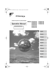
1
Aurora Series
Single Phase ELI System
10 KW – 15 KW
Service Manual
M4006_Aurora_10-15Kw_Service_Manual V3.0 2012-06-14
M4006_Aurora_10-15Kw_Service_Manual V3.0 2012-06-14
i
NOTE
The instructions contained in this manual are not intended to cover all of the
details or variations in equipment, or to provide for every possible contingency
to be met in connection with installation, operation, or maintenance. Should
further information be desired or should particular problems arise which are not
covered sufficiently for the purchaser’s purposes, the matter should be referred
directly to Always On.
Any electrical or mechanical modifications to this equipment, without prior
written consent of Always On, will void all warranties and may void UL/cUL
listing. Unauthorized modifications may also result in personal injury, death,
and damage to the equipment.
Dear Customer,
Thank you for selecting our emergency lighting inverter (ELI). We are pleased to
include you as one of our valued Always On customers!
We are confident that this emergency lighting inverter system, developed and
manufactured in our ISO 9001 certified facilities, will provide the quality and
satisfaction you demand.
Please read this installation manual carefully as it contains the necessary
information required to install the ELI properly.
Thank you for choosing Always On.
M4006_Aurora_10-15Kw_Service_Manual V3.0 2012-06-14
ii
Preface
Congratulations on your choice of our emergency lighting inverter (ELI).
This equipment has been manufactured and tested using methods and procedures equivalent to
UL 924.
This manual describes the recommended procedures for installing the ELI.
While every effort has been made to ensure the completeness and accuracy of this manual,
Always On assumes no responsibility or liability for any losses or damages resulting from the use
of the information contained in this document.
WARNING: This manual is intended to provide installation instructions only.
The information contained in this manual is to be used as a guideline and
recommendation only. Only qualified personnel should perform installation
and maintenance. Factory authorized personnel shall inspect installation
prior to start up and commissioning to validate warranty. Failure to follow
this directive will void the warranty.
We recommend that this manual be kept with the ELI for future reference. If any problems are
encountered with the procedures contained in this manual, please contact our Service Centre
before proceeding.
This document may not be copied or reproduced without the explicit written permission of Always
On.
Due to technical advancements and improvements, some of the information contained in this
manual may be changed or modified without prior notice.
M4006_Aurora_10-15Kw_Service_Manual V3.0 2012-06-14
iii
Symbols
The following symbols are used through out this manual.
Warning Information
This symbol alerts you to important information.
Electrical Hazard
This symbol indicates an electrical hazard may be present.
Electrical Symbols
Protective grounding terminal; a terminal that must be connected to ground prior to
making any other connection to the equipment.
A terminal to/from which an alternating current or voltage may be applied/supplied.
A terminal to/from which a direct current or voltage may be applied/supplied.
This symbol indicates the word “phase”.
M4006_Aurora_10-15Kw_Service_Manual V3.0 2012-06-14
iv
Safety Instructions
READ AND FOLLOW ALL SAFETY INSTRUCTIONS.
SAVE THESE INSTRUCTIONS.
This manual contains important safety instructions that should be followed during installation and
maintenance of the ELI system and optional packages. Before the installation process begins, we
recommend that the installer read through the safety precautions, operators manual and the
option installation instructions, taking all necessary safety precautions to protect themselves and
the equipment being installed.
GENERAL
Move the ELI in an upright position, in its original packaging, to its final destination.
To lift the cabinets, use a forklift or lifting belts with spreader bars.
- Check for sufficient floor and elevator loading capacity.
-
Check the integrity of the ELI equipment carefully.
If visible damage is evident, do not attempt to install or start the ELI. Contact the transport
delivery company immediately, file a claim with the transport company and inform Always
On directly.
-
Do not use outdoors
-
The use of accessory equipment not recommended by Always On may cause an unsafe
condition
-
WARNING! RISK OF ELECTRICAL SHOCK: use extreme caution when removing covers.
- All maintenance and service work should be performed by qualified and trained service
personnel. The ELI may contain its own energy source, (batteries) which can be dangerous to
the untrained person. This ELI contains potentially hazardous voltages
- The field-wiring terminals may be electrically live, even when the ELI is not connected to
the utility.
- Use caution when servicing batteries. A battery can present a risk of electrical shock, burn
from high short-current. Battery acid can cause burns to skin and eyes. If acid is spilled on
skin or in eyes, flush with fresh water and contact physician immediately.
-
When replacing batteries use the same number and type (sealed-cell lead acid).
- Proper disposal of batteries is required. Refer to your local codes for disposal
requirements.
M4006_Aurora_10-15Kw_Service_Manual V3.0 2012-06-14
v
- Dangerous voltages may be present during battery operation. The batteries must be
disconnected during maintenance or service work. (Open battery breaker or fuses)
-
Be aware that the inverter can restart automatically after the utility voltage is restored.
Do not use this equipment for other than intended use.
M4006_Aurora_10-15Kw_Service_Manual V3.0 2012-06-14
vi
INSTALLATION
-
This ELI is intended for use in a controlled indoor environment free of conductive
contaminants and protected against any type of intrusion.
Do not install the ELI in an excessively humid environment or near water.
Avoid spilling liquids and/or dropping any foreign object(s) onto the ELI.
The unit must be placed in a sufficiently ventilated area; the ambient temperature should not
exceed 40°C (104°F).
Optimal battery life is obtained if the ambient temperature does not exceed 25°C (77°F).
HIGH GROUND LEAKAGE CURRENT: ground connection completed before connecting the
AC voltage wires on the input!
Switching OFF the ELI does not isolate the ELI from the utility as the utility supply is still HOT
at the input terminal strip. Supply breaker needs to be opened.
It is important that air can move freely around and through the unit. Do not block the air vents.
Avoid locations in direct sunlight or near heat sources (gas or electric heaters).
STORAGE
-
Store the ELI in a dry location free of contaminants;
Storage temperature must be within -25°C (-13°F) to 55°C (131°F).
If the unit is stored for a period exceeding 3 months, the batteries must be recharged
periodically (time depending on storage temperature).
WARNING!
LETHAL VOLTAGES MAY BE PRESENT WITHIN THIS UNIT EVEN WHEN IT IS
APPARENTLY NOT OPERATING. OBSERVE ALL CAUTIONS AND WARNINGS IN THIS
MANUAL. FAILURE TO DO SO COULD RESULT IN SERIOUS INJURY OR DEATH. REFER
UNIT TO QUALIFIED SERVICE PERSONNEL IF MAINTENANCE IS REQUIRED. NO ONE
SHOULD WORK ON THIS EQUIPMENT UNLESS THEY ARE FULLY QUALIFIED TO DO SO.
AN INSTALLER SHOULD NEVER WORK ALONE.
WARNING!
WHEN REMOVING POWER FROM THE ELI, ALLOW FIVE MINUTES FOR CAPACITORS TO
DISCHARGE BEFORE WORKING ON THE EQUIPMENT.
CAUTION!
This equipment complies with the requirements in Part 15 of FCC rules for a Class A
computing device. Operation of this equipment in a residential area may cause
interference to radio and TV reception, requiring the operator to take whatever steps
necessary to correct the interference.
CAUTION!
Do not put option control wiring in the same conduit as the ELI input or output power
cables.
M4006_Aurora_10-15Kw_Service_Manual V3.0 2012-06-14
vii
THIS SAFETY NOTICE IS ADDRESSED TO THE ALWAYS ON
CUSTOMER ENGINEERS WHO PERFORM MAINTENANCE OF THE
UNINTERRUPTIBLE POWER SUPPLY (ELI) SYSTEMS.
Electrical Safety
• Maintenance work to be performed by a factory trained customer engineers, or qualified
personnel. Extremely dangerous voltage levels can exist within the ELI system. Extreme
caution must be used.
• Ensure system is in maintenance bypass mode or external wrap-around bypass mode
before work is started.
• This manual is designed as an aid tool in diagnosing problems that may arise. Always On
does not assume responsibility if information causes injuries.
• Apart from the front door, do not open any other part of the ELI without consulting the
factory first. Before removing the protection screens, be sure that the unit is completely
powered off.
• Be aware that dangerous voltage can be supplied by the internal battery or electrolytic
capacitors.
• When system is in bypass mode and all fuses have been opened dangerous voltages may
exist within the ELI system. Use extreme caution when exchanging boards and working
inside the unit.
READ AND FOLLOW ALL SAFETY INSTRUCTIONS.
SAVE THESE INSTRUCTIONS.
M4006_Aurora_10-15Kw_Service_Manual V3.0 2012-06-14
viii
TABLE OF CONTENTS
1.
2.
3.
4.
5.
6.
Introduction............................................................................................................................... 1
1.1.
Overview........................................................................................................................... 1
1.2.
Features............................................................................................................................ 1
1.3.
Definitions......................................................................................................................... 2
Theory of Operation ................................................................................................................ 3
2.1.
Block Diagram.................................................................................................................. 3
2.2.
ELI Subsystems............................................................................................................... 4
2.3.
Modes of Operation ........................................................................................................ 5
Physical Topology ................................................................................................................... 7
3.1.
Front view ......................................................................................................................... 7
3.2.
Battery Cabinets .............................................................................................................. 9
User Interface ........................................................................................................................ 10
4.1.
Front Control Panel....................................................................................................... 10
4.2.
Normal Display .............................................................................................................. 10
4.3.
Button Operation ........................................................................................................... 10
4.4.
ELI Metering Display..................................................................................................... 12
4.5.
Control Panel Lights...................................................................................................... 12
4.6.
Audible Alarm................................................................................................................. 12
Communication Interfaces ................................................................................................... 13
5.1.
RS-232 Port.................................................................................................................... 14
5.2.
AS-400 & Relay Contact Port...................................................................................... 14
5.3.
Dry Contact .................................................................................................................... 16
5.4.
Emergency Power Off .................................................................................................. 16
5.5.
Emergency Lighting Notification ................................................................................. 17
Optional Features.................................................................................................................. 18
6.1.
Simple Network Management Protocol (SNMP) Adapter....................................... 18
6.2.
Monitoring and Optional Control Software ................................................................ 18
M4006_Aurora_10-15Kw_Service_Manual V3.0 2012-06-14
ix
6.3.
7.
Normally Off Function................................................................................................... 18
OPERATION .......................................................................................................................... 19
7.1.
Start-up Procedure........................................................................................................ 19
7.2.
Shutdown Procedure .................................................................................................... 19
7.3.
Test Procedure .............................................................................................................. 20
7.4.
Maintenance Bypass Procedure................................................................................. 20
7.5.
Manual Battery Test:..................................................................................................... 21
8.
TROUBLESHOOTING ......................................................................................................... 22
9.
Layout Details ........................................................................................................................ 23
9.1.
Circuit Boards ................................................................................................................ 23
9.2.
10 kW to 15 kW Unit Pictures – Layout ..................................................................... 24
10.
Technical Specifications................................................................................................... 28
11.
Contact Information........................................................................................................... 32
M4006_Aurora_10-15Kw_Service_Manual V3.0 2012-06-14
x
1. INTRODUCTION
Congratulations on your choice of the Aurora On-Line Emergency Lighting Inverter (ELI). This ELI
features the latest top of the line microprocessor technology and IGBT transistors and provides
clean, highly regulated and pulse width modulated (PWM) true sine wave power.
1.1. Overview
This ELI is designed for installation between your AC power supply (utility or generator)
and your lighting equipment. It provides power to your equipment during major power
events such as blackouts and brownouts, over-voltage and under-voltage conditions. The
ELI provides a consistent supply of regulated AC power during these power events,
allowing you to ensure safety and lighting for the period required.
1.2. Features
This ELI provides full time self-diagnostics as well as two levels of audible alarms when
the unit is operating in battery mode. Along with the current mode of operation, the LCD
screen displays critical system information including:
•
Percent Load, Watt, VA
•
Remaining battery capacity, battery voltage
•
Input voltage,
•
Output voltage,
•
Input frequency,
•
Output frequency and
•
Internal ELI temperature.
A manual test switch has been incorporated into the input/test breaker that makes testing
a simple procedure. The internal bypass switch allows maintenance on the ELI to be
performed without interruption of power to the load.
The communications port, in conjunction with multi-platform monitoring and control
software, enables the unit to be connected to a local or networked computer system.
Detailed operating information including voltages, currents, and alarm status is available to
the monitoring system.
Other communications options include:
•
An SNMP adapter to remotely control and monitor the unit via a network or the
Internet.
•
An AS-400 interface to allow for relay communications in PLC or dry contact
environments.
M4006_Aurora_10-15Kw_Service_Manual V3.0 2012-06-14
1
1.3. Definitions
•
•
•
•
•
•
•
•
•
•
•
•
•
•
Critical Load
These are loads that require clean, regulated and continuous AC power and which
are connected to the output of the ELI module
ELI Module
The portion of the ELI system that contains one or more of: the rectifier / DFC,
charger, inverter, static bypass switch, maintenance bypass switch, controls,
monitoring, and indicators.
Rectifier / DFC
Contained in the ELI module. Responsible for converting the normal AC input
power to DC power and supplying the inverter with DC power.
Charger
Contained in the ELI module. Responsible for recharging the batteries.
Inverter
Contained in the ELI module. Responsible for converting DC power (supplied by
the rectifier) to regulated and filtered AC power that is then supplied to the critical
loads.
Static Bypass Switch
Contained in the ELI module. Responsible for automatically transferring the
attached load, without interruption, from the inverter AC output to the bypass AC
power source in the event of an overload or degradation of the inverter’s
performance.
Maintenance Bypass Switch:
Contained in the ELI module. Used to transferring the attached load, without
interruption, from the inverter AC output to the bypass AC power source while
electrically isolating the static bypass switch, rectifier / DFC, charger and inverter.
Used for maintenance purposes.
Battery
The battery system provides DC power to the inverter input when the normal AC
input power to the ELI fails.
IGBT
Isolated Gate Bipolar Transistor.
PWM
Pulse Width Modulation.
ELI
Emergency Lighting Inverter.
BBU
Battery Backup Unit.
PFC
Power Factor Correction.
EPO
Emergency Power Off.
M4006_Aurora_10-15Kw_Service_Manual V3.0 2012-06-14
2
2. THEORY OF OPERATION
The ELI uses a variety of technologies, working in tandem to provide clean reliable power and
protect the critical loads. The first stage in the protection process uses a transformer to electrically
isolate the unit from the AC source. The input power is then passed through a surge and EMI/RFI
filter to remove fluctuations in high frequency and protect against power surges and transients.
The rectifier then takes over and converts the AC power to DC, providing a constant voltage. The
charger circuit provides regulated DC power to the batteries. The DC power is then fed to the
inverter. The inverter converts the supplied DC power into clean, reliable AC power. An output
isolation transformer electrically isolates the ELI from the critical loads and an output filter
provides protection from power fluctuations caused by equipment on the critical load circuit. A
switch allows for manual bypass. An output breaker allows for output switching.
2.1. Block Diagram
Figure 2-1 ELI Block Diagram
M4006_Aurora_10-15Kw_Service_Manual V3.0 2012-06-14
3
2.2. ELI Subsystems
•
•
•
•
•
•
•
•
•
Input Transformer
A transformer is factory installed in the ELI Cabinet and connected to the AC input
power supply.
Input Breaker
The input breaker prevents the main distribution panel breaker from tripping when
a ELI fault or over-current condition occurs. It also acts as a test switch for
performing back-up mode tests.
Input EMI/RFI Filter
This filter attenuates any electrical noise in the input AC power supply.
Input surge protector
Provides protection to the ELI and equipment from power surges and transients
such as lightning and phase-to-phase faults.
Rectifier/Power Factor Correction
During normal operation, the rectifier circuit converts the utility power (AC power)
to DC power. The inverter uses the DC power to generate the AC output
waveform. At the same time, the Rectifier/PFC circuit ensures that the waveform of
the input current used by the ELI Inverter is close to ideal. This type of conversion
and state of the art technology maintains two key objectives: the utility power is
used as efficiently as possible, and the amount of distortion reflected back to the
utility is minimized therefore providing cleaner power to other devices in the
building not being protected by the ELI.
• PFC Control Note
By utilizing control circuits, the current drawn from the utility power is in-phase with
the input voltage. The control circuit also allows the ELI to have a broader input
voltage range (±25%).
Charger
During normal operation, the charger converts AC voltage drawn from utility power
into regulated DC voltage, which charges the batteries and maintains the batteries
at the desired level by a float charge.
Batteries
The batteries provide power to the critical load when the input power is interrupted.
Battery sizes vary between series and series-parallel configurations. All batteries
are sealed lead-acid valve regulated gel cells.
Battery Breaker
This breaker is used to connect and disconnect the batteries to and from the ELI
system.
Inverter
The inverter’s solid-state electronics convert DC provided by the rectifier / DFC or
batteries to AC power. The inverter will produce 50 or 60Hz (auto-selected) using
IGBT technology that switches at ~18kHz. This is above the audible frequency
range and does not generate low frequency magnetic components. The inverter
uses PWM to generate and regulate the pure sine wave AC output with a very
small tolerance (±2%).
M4006_Aurora_10-15Kw_Service_Manual V3.0 2012-06-14
4
•
•
•
Static by-pass
A static transfer switch and bypass circuit is provided as an integral part of the ELI.
The inverter has an overload rating of 150% rated load for 20 seconds, 200% rated
load for one and a half cycles. The static bypass will auto transfer to bypass if
these overload conditions are exceeded. The static transfer switch control logic
contains an automatic transfer control that senses the status of the inverter logic
signals as well as operating and alarm conditions. This control circuit provides an
uninterrupted transfer of the load to a normal input source. Transfers are also
made when an overload or malfunction occurs within the ELI, without exceeding
the transient limits specified herein.
Maintenance bypass switch
The maintenance bypass switch is used to transfer the attached load, without
interruption, from the inverter AC output to the bypass AC power source while
electrically isolating the static bypass switch, rectifier, charger and inverter.
Output Isolation Transformer
An output isolation transformer factory installed in the ELI cabinet and connected to
the ELI output. It provides galvanic isolation between the ELI and the critical load.
Output breaker
Allows the ELI output to be shutdown without operating the inverter controls.
2.3. Modes of Operation
•
•
•
•
The ELI is designed to operate continuously as an on-line, dual conversion system
in the following modes:
Normal Mode
The rectifier converts the utility or AC source input to DC and then supplies the DC
current
to the inverter unit. The inverter unit continuously supplies the attached load with
regulated AC power. The output voltage is precisely regulated at all times
regardless of the input voltage.
Back-Up Mode
When the AC input power is interrupted, the inverter is supplied with power from
the storage batteries without interruption. There are no interruptions to the output
voltage or waveform during transfer to battery power.
Recharge
When AC input power is restored, the rectifier / DFC will automatically restart and
continue to supply power to the inverter. The charger re-charges the battery.
Automatic Restart
During an extended input power outage that leads to a complete battery discharge,
the unit will automatically shutdown. When input power is restored, the unit will
automatically restart and resume supplying power to the load and battery charger.
M4006_Aurora_10-15Kw_Service_Manual V3.0 2012-06-14
5
•
Static Bypass
The bypass provides an alternate path (other than the regulated path) for power to
reach the load. The bypass can be activated by two different methods:
o
Automatic
In the unlikely event of an internal failure or an inverter overload, the unit
will perform an automatic transfer of the load from the inverter to the bypass
source.
o
Manual
Should the unit need to be taken out of service for maintenance or repair,
manual activation of the bypass will cause an immediate transfer of the load
from the inverter to the bypass source. The input rectifier, inverter, and
battery charging operations will be interrupted until the user transfers the
ELI back to normal operation
•
Free Run Mode
The ELI operates in free run mode when input frequency is outside of the selected
input frequency setting. Free run mode is when output frequency does not match
input frequency. When starting the ELI, the frequency regulation detected is 50 or
60 Hz ±0.25Hz.
Diagnostic tests
When you start the ELI, a diagnostic test is automatically executed that checks the
electronics and battery and reports any problems on the LCD display. An advanced
battery management system continuously monitors the conditions of the batteries
sending a warning if replacement is needed. A battery discharge test is performed
every 30 days of normal operation, and, if a problem arises it will be reported on
the LCD display. Other than during the initial 24 hours after start-up or while the
ELI is in charging mode, diagnostic tests can be performed manually from the front
panel at any time.
•
M4006_Aurora_10-15Kw_Service_Manual V3.0 2012-06-14
6
3. PHYSICAL TOPOLOGY
3.1. Front view
Figure 3-1 Front view of the ELI
M4006_Aurora_10-15Kw_Service_Manual V3.0 2012-06-14
7
Figure 3-2 Front Doors Open
Removal of the rear access cover exposes personnel to dangerous
voltages and shock hazards that may cause damage, injury or death.
M4006_Aurora_10-15Kw_Service_Manual V3.0 2012-06-14
8
3.2. Battery Cabinets
Some battery cabinets feature slide-out shelves. Prior to installation of the BBU, the side
panels should have been removed and the screws holding the battery slide-out shelves in
place should have been unscrewed, allowing for ease of battery replacement.
CAUTION! Only qualified service personnel should attempt battery
bank maintenance. Removal of the side access panels exposes
personnel to potential dangerous voltages and shock hazards that
may cause damage, injury or death.
If screws have not been properly removed prior to BBU installation, completely shut down
ELI, wait for 30 minutes until capacitors have fully discharged and disconnect ELI from
BBU prior to servicing.
Figure 3-4 Slide-out BBU shelves
M4006_Aurora_10-15Kw_Service_Manual V3.0 2012-06-14
9
4. USER INTERFACE
4.1. Front Control Panel
Figure 4-1 Front Control Panel of ELI
4.2. Normal Display
The LCD displays the operating status of the ELI. From here you have a choice to go to
ELI meters display and the settings display by pressing the “STATUS” or “FUNC”
buttons.
4.3. Button Operation
There are three operating buttons on the front panel:
• “ON/ OFF” button:
o
Push the “ON/OFF” button for at least 3 seconds to turn on the ELI.
o
When ELI is running, push the “ON/OFF” button for at least 3 seconds to
turn off the ELI.
• “FUNC” button. ( WARNING: Factory settings, authorized personnel only )
This button is used to check ELI configuration information
o
o
o
o
o
o
o
o
Push the “FUNC” button for at least 2 seconds to choose the function that
you want.
Move between items by pressing the “FUNC” button once. (See table 7-2)
Each function can be displayed by pressing the button once, and there are
fourteen different settings to choose from.
Push the “ENTER” button to choose the selected setting.
Push the function button to select desired parameter.
Push the “ENTER” button to save your setting.
Push the “ENTER” button to confirm and enable the selected setting.
If nothing has been pressed for 10 seconds, the display will return to
original status.
M4006_Aurora_10-15Kw_Service_Manual V3.0 2012-06-14
10
Settings
O/P Wire Set
I/P Wire Set
Input Frequency
LCD Display
O/P Voltage
Setting
I/P Voltage
Setting
I/P Frequency
Setting
Input/Bypass Voltage I/P Bypass
Set
Free Run Mode
Explanation
Selection
Select nominal output
120/208/240/277/347
voltage
Select nominal input
120/208/240/277/347
voltage
Select input frequency
±2%
range when ELI goes into ±5%
free run mode
±7%
Select input voltage
range when bypass is
available
±10%
-10 to +15%
-15 to +20%
ON/OFF
Free Run Set Select if ELI can run in
Free Run Mode
(unsynchronized)
Bypass
Bypass
If enable is chosen, the Enable/Disable
Enable/Disable at
Disable
ELI can go to bypass
Free Run Mode
when unsynchronized.
HE Mode Setting
HE Mode Set Select if ELI runs in
ON/OFF
efficiency optimizer mode
Force Manual Bypass Manual
Permanently force ELI to ON/OFF
Bypass
bypass. For service only
Do Battery Test
Battery Test Detect battery is within
normal parameters
Silence Function
Silence Set Enable or disable silence ON/OFF
function
Number of External Bat Cabinet This setting is needed for 30
Battery Packs
Set
ELI's to predict expected 60
back-up time
90
Site Wiring Alarm
Site Fault Set You can enable or
Enable/Disable
disable the site wiring
alarm
Select Language
Language
Select display language English / German /
French / Spanish /
Italian
Set Generator Mode Generator
Set unit in generator
ON/OFF
mode
Set RS-232
RS-232
Set RS-232
Enable/Disable
Communication
Control
communications on or off
Default
OPV
IPV
±5%
-10 to
+15%
ON
Disable
OFF
OFF
OFF
Disable
English
OFF
Enable
Table 4-1 ELI Configuration
M4006_Aurora_10-15Kw_Service_Manual V3.0 2012-06-14
11
4.4. ELI Metering Display
Various measurements are available through the ELI meters display; pressing the
“STATUS” button will scroll through the following meters.
LCD Message
O/P VOLT=***.*V
O/P FREQ=**.*Hz
I/P VOLT=***.*V
I/P FREQ=**.*Hz
BAT VOLT=**.*V
O/P Load%=**%
O/P W=*W
O/P VA=*VA
O/P Curr=*A
BACKUP TIME=**min
BAT CHARG=**%
TEMPERATURE=**C
BAT PACK NUM=*
RATING=****VA
CPU VERSION **.*
Description
Shows Output AC voltage
Shows Output Frequency
Shows Input AC Voltage
Shows Input Frequency
Shows Battery Voltage
Shows % of Maximum Rated Load
Shows Output Watts
Shows Output VA
Shows Output Current
Shows Estimated Backup time in minutes
Shows approximate % of battery capacity
Shows approximate ambient temperature
Shows External Battery Packs Number
Shows ELI Rating
Shows CPU Version
Table 4-2 ELI Meters
4.5. Control Panel Lights
Operation of the ELI is indicated on the monitor panel with five LED indicators
• ON-LINE
When the ELI is in normal or static bypass modes, there is voltage at the output
terminals and this LED will light up in green.
• ON-BAT
This LED is lit while the unit is operating in battery mode.
• BYPASS
While the unit is operating in bypass mode, this LED will light up in yellow.
• FAULT
If an internal error occurs in the ELI, this LED will light up in red.
4.6. Audible Alarm
Pressing any button on the front of the ELI will silence the audible alarm. The audible
alarm will sound when the ELI enters one of the following states.
• Backup Mode
The ELI will beep once every five (5) seconds and the BACKUP LED will illuminate
(beep - - - - beep - - - - beep) [Slow beep]
• Low Battery
The ELI will beep once every second when the batteries are almost depleted.
(beep - beep - beep) [Fast beep]
• Fault
The ELI will sound a continuous beep and the FAULT LIGHT indicator will illuminate.
(beeeeep) [Continuous beep]
M4006_Aurora_10-15Kw_Service_Manual V3.0 2012-06-14
12
5. COMMUNICATION INTERFACES
There are three types of communication interfaces available on the standard ELI, RS-232, Dry
Contact and AS-400. There is also an SNMP adaptor available as an option.
RS232
ALARM PANEL
GND
N
L1
B+
GND
8
6
5
3
4
9
L2
7
BATTERY
OUTPUT
1
L2
1
2
INPUT
L1
B-
INPUT/OUTPUTPOWER
SNMP AS400
Figure 5-1 Communication Interfaces
M4006_Aurora_10-15Kw_Service_Manual V3.0 2012-06-14
13
5.1. RS-232 Port
A 9-pin female SUB-D connector is located on the ELI front panel to provide a
communications link between the ELI and a computer. The optional software package and
cable allows you to connect the ELI to a computer and monitor the operating status of the
ELI system.
Pin #
2
3
5
6
8
9
Signal Name
TxD
RxD
Common
CTS
DCD
RI
Direction (Ref. ELI)
Output
Input
Functions
TxD Output
RxD / Inverter Off Input
Common
Output
AC Failure Output
Output
Low Battery Output
Output
+8 to 24VDC Power
Table 5-1 RS-232 Pinout
5.2. AS-400 & Relay Contact Port
Located on the front panel of the ELI is a 25 Pin connector, which provides status
information through relay contacts and control by photo-coupled inputs.
Figure 5-2 AS-400 Communication Interface
M4006_Aurora_10-15Kw_Service_Manual V3.0 2012-06-14
14
Pin Assignment (DB 25pin male connector)
• Input signal pin assignment
o Remote emergency power off: Pin 24, 25
o Remote shut down: Pin 22, 23
o If Vpin22 > Vpin23 (5V~12V), the ELI will power off after a 1 second delay.
• Output signal pin assignment:
o Fault
Pin 1, 2, 3
o On Battery
Pin 4, 5, 6
o Battery Low Pin 7, 8
o On Bypass
Pin 9, 10
o On Inverter
Pin 11,12
• Dry Contact Capacity
o Total maximum power rating is 30W
o Maximum voltage rating is 250VAC
o Maximum current rating is 3A
• Optional Features
o Instrumentation Terminal Strip
Allows for easy connection of wires if 25pin connector not available
State
Pin 1,2
Pin 2,3
Pin 4,5
Pin 5,6
Pin 7,8
Pin
9,10
Open
Closed
Open
Open
Pin
11,12
Closed
Open
Closed
Closed
Normal
Fault
On Battery
Battery
Low
On Bypass
On Inverter
Open
Closed
Open
Open
Closed
Open
Closed
Closed
Open
*1
Closed
Closed
Closed
*1
Open
Open
Open
*1
*1
Closed
Closed
*1
*1
*1
*1
*1
Open
Closed
Open
*1
*1
*1
*1 = Inactive. State may be “open” or “closed” condition
Open
Closed
Table 5-2 Output Truth Table for the AS-400 pins
M4006_Aurora_10-15Kw_Service_Manual V3.0 2012-06-14
15
5.3. Dry Contact
Dry contact outputs are provided through the RS-232 port located at the front of the ELI.
Each output contact provides status information of the ELI operation. These contacts
enable the ELI to notify a computer or automation device being supported by the ELI of a
power anomaly. The connected device may then be programmed to recognize these
signals and initiate a shutdown sequence.
The ELI reads the input signal through a photo-coupled diode transistor pair, so your
control equipment remains electrically isolated. The photo-coupled transistor is capable of
a maximum conduction level of 40VDC at 40mA.
Figure 5-3 Photo-coupled Transistor
5.4. Emergency Power Off
A customer-supplied switch may be located remotely as an emergency stop button for the
ELI. The switch may be used to open the EPO jumper connection and force ELI output to
switch off. Since the EPO shuts down the equipment immediately, the power management
software is prevented from performing an orderly shutdown. The ELI will have to be
manually restarted with the EPO jumper closed again in order to reconnect power to the
load. The ELI comes with a simple jumper in place of the push button so that it runs
without a switch.
M4006_Aurora_10-15Kw_Service_Manual V3.0 2012-06-14
16
5.5. Emergency Lighting Notification
CONTACT RATING
3A / 120 VAC
30 WATTS
NORMALLY OPEN
CONTACTS
The fire alarm panel connections are provided to allow the fire alarm panel recognition of the
following fault conditions using normally open contacts of the ELI Bypass Status:
1) Output overload condition.
2) Inverter failure due to:
a. Output short circuit.
b. Inverter fuse open.
c. Over temperature condition.
d. Inverter overload condition.
e. Inverter stop activation.
f. Inverter output outside or parameters.
g. Bypass activated.
h. Inverter shutdown.
3) Battery low Inverter shutdown condition.
4) No output voltage present.
M4006_Aurora_10-15Kw_Service_Manual V3.0 2012-06-14
17
6. OPTIONAL FEATURES
6.1. Simple Network Management Protocol (SNMP) Adapter
The Always On Simple Network Management Protocol (SNMP) adapter is a web-based
management product that uses multiple, open standards such as Telnet, HTTP, and
SNMP to provide full management of supported devices.
The SNMP Adapter is designed to connect directly to the network and allow network
broadcasting of ELI conditions as well as remote access to the ELI system to monitor
parameters and displays.
For set-up instructions view the READ ME file provided with the set-up disk.
6.2. Monitoring and Optional Control Software
The optional power management software offers powerful features such as the ability to
monitor local ELI's, as well as remote units via a TCP/IP network, from your central
location. It can notify you of any problems automatically, by sending email or by dialling
your pager through a modem when an event such as a power outage occurs. The
software is capable of broadcasting messages to remote computers and can even send
them commands to shutdown.
The GUI is a real time graphical display of ELI status including input/output voltage,
frequency, load, temperature, and capacity. There is also a data-logging feature included.
The software can be configured to schedule battery tests. The software can also shutdown
the system in a safe fashion before the batteries run out in the case of an extended
blackout.
•
•
•
Install the software package according to the instructions included with CD.
Connect the ELI to the computer using the RS-232 cable included.
Start the software.
6.3. Normally Off Function
All Normally Off loads shall not exceed 50% of the ELI rating per phase.
M4006_Aurora_10-15Kw_Service_Manual V3.0 2012-06-14
18
7. OPERATION
Not following the start-up and shutdown procedures correctly can
damage the system or cause injury.
7.1. Start-up Procedure
• Open front door of ELI.
• Remove breaker panel cover on front of ELI.
• Confirm MAINTENANCE SWITCH is in “NORMAL” position.
• Confirm BATTERY BREAKER is in OFF position.
• Confirm INPUT BREAKER is in OFF position.
• Open battery cabinet door.
• Turn ON all BATTERY BREAKERS on battery cabinet(s).
• Turn ON BATTERY BREAKER on front of ELI.
• Wait 10 seconds.
• Apply utility power to ELI.
• Turn ON the INPUT BREAKER on front of ELI.
ELI will enter stand-by mode.
• Turn ON the OUTPUT BREAKER on front of ELI.
• Push “ON/OFF” button on front panel (hold button for 3 seconds or until ELI beeps and
displays “READY ON”.)
The unit will automatically perform a self-test and then go to line mode.
7.2. Shutdown Procedure
• Shut down and turn off all the attached loads.
• Push the “ON/OFF” button on the front panel for five seconds.
The alarm will sound and the ELI will shutdown.
The LCD will display “UPS OFF” for a few seconds and then shut down fully.
• Open the OUTPUT BREAKER on the front of the ELI.
• Open the INPUT BREAKER on the front of the ELI and wait 10 seconds.
• Open the BATTERY BREAKER on front of ELI.
• Open all the BATTERY BREAKERS on battery cabinet.
ELI is completely shutdown.
Remove input power from ELI.
M4006_Aurora_10-15Kw_Service_Manual V3.0 2012-06-14
19
7.3. Test Procedure
The ELI input / test breaker is used to test the ELI for backup operation with only one
simple operation.
7.3.1. Starting the Test
•
Turn the INPUT/TEST BREAKER to the “OFF/TEST” position.
This puts the ELI in backup mode while loaded.
The load will not see a power fluctuation if the ELI is functioning correctly.
LCD will display status of ELI during test.
7.3.2. Stopping the Test
•
Turn the INPUT / TEST BREAKER back to the “ON” position.
7.4. Maintenance Bypass Procedure
Maintenance Mode is used to bypass the inverter portion of the ELI without disrupting the
load. When the INPUT BREAKER is closed, the ELI tracks the phase of the input
waveform and the transition from inverter mode to maintenance mode is seamless
provided that the utility is functioning satisfactorily.
7.4.1. Entering Maintenance Bypass Mode
•
Use the front panel “FUNC” button to place the unit into bypass mode.
Bypass LED will light
• Remove front access panel.
• Turn MAINTENANCE SWITCH to “BYPASS” position.
• Push the “ON/OFF” button on the front panel for five seconds.
The alarm will sound and the ELI will shutdown.
• The LCD will display “UPS OFF” for a few seconds and then shut down fully.
ELI will power down.
LCD will go out.
• Open the INPUT BREAKER on the front of the ELI and wait 10 seconds.
WARNING: DO NOT OPEN OUTPUT BREAKER. THIS WILL
SHUTDOWN LOADS IMMEDIATELY.
•
•
Open the BATTERY BREAKER on front of ELI.
Open all the BATTERY BREAKERS on battery cabinet.
WARNING: Make sure AC Input and Battery Circuit Breakers are in the
“Open” position before working on the ELI inverter in Maintenance
Mode.
M4006_Aurora_10-15Kw_Service_Manual V3.0 2012-06-14
20
7.4.2. Restoring normal operation
•
•
•
•
•
Turn ON all BATTERY BREAKERS on battery cabinet.
Turn ON BATTERY BREAKER on front of ELI.
Wait 10 seconds.
Apply utility power to ELI.
Turn ON the INPUT BREAKER on front of ELI.
ELI will enter stand-by mode.
•
Push “ON/OFF” button on front panel (hold button for 3 seconds or until ELI beeps and
displays “READY ON”).
The unit will automatically perform a self-test and then go to line mode.
Use the front panel “FUNC” button to place the unit into bypass mode.
Bypass LED will illuminate.
On the front panel, turn the MAINTENANCE SWITCH to the “NORMAL” position.
Use the “FUNC” button to turn off the manual bypass mode.
ELI will start inverter and enter inverter mode.
Bypass LED will go out.
Line LED will illuminate.
The ELI is now in Normal Operating Mode.
•
•
•
7.5. Manual Battery Test:
To be performed by authorized service personnel only.
To initiate a manual battery test, turn off the input breaker to disconnect all ungrounded
conductors. This process will simulate a failure of utility supply.
Battery status will be displayed via the front panel controls and LCD for the duration of the
test.
M4006_Aurora_10-15Kw_Service_Manual V3.0 2012-06-14
21
8. TROUBLESHOOTING
Displayed on LCD
Output Overload
Audible Alarm
Two beeps per second
Alarm Description
The ELI is overloaded in
line mode. Your
equipment needs more
power than the ELI can
provide. The ELI
operates in bypass.
Battery Test
No beeps
The ELI is doing a
battery test.
Over-Charge
Constant beep
Batteries are
overcharged.
Low Battery
Two beeps every 5
seconds
On-Battery
Once every 5 seconds
The unit is operating on
Battery Power and will
shut down soon due to
very low battery voltage.
The unit is operating on
Battery Power.
Charger Fail
Over Temperature
Constant beep
Constant beep
Charger has failed.
High ambient
temperature.
Output Short
High Output Voltage
Low Output Voltage
Bus Fault
Constant beep
Constant beep
Constant beep
Two beeps per second
Output short circuit.
High output voltage.
Low output voltage.
High internal DC bus
voltage.
Line Abnormal
One beep per second
Wrong AC Line backed
up during auto restart.
M4006_Aurora_10-15Kw_Service_Manual V3.0 2012-06-14
What You Should Do
Shut off the least
important equipment
connected to the ELI. If
this solves the overload
problem the ELI will
switch from bypass back
to normal operation.
No action needed. The
ELI will return to normal
operation when it
successfully completes
the battery test.
Turn off protected loads.
Turn off the ELI and call
your local dealer.
The unit will restart
Automatically when
acceptable power
returns.
Save your data and
perform a controlled
shutdown.
Call the local dealer.
Make sure the unit’s
fans and vent holes are
not blocked. Make sure
the ambient surrounding
temperature is not
above 40°C. If these
conditions did not solve
the problem call your
service representative.
Call the local dealer.
Call the local dealer.
Call the local dealer.
Turn off protected loads.
Turn off the ELI and call
your local dealer.
22
9. LAYOUT DETAILS
9.1. Circuit Boards
•
•
•
•
LCD Control Panel
o
This is the front panel user interface.
o
Displays data as received from the CPU Board.
o
Provides interface to control the function of the ELI, by front panel ON/OFF,
FUNC, STATUS, ENTER and ESCAPE buttons.
CPU Board
o
Contains the main microprocessor that provides monitoring and control of the
main functions of the ELI system.
o
Provides data display and user interface to LCD panel.
o
Provides communications to the DB9 connector via the RS232 TX and RX
o
Provides open collector dry contact status.
o
Generates synchronizing and control signals for the inverter section of the
ELI.
o
Sends status information to the AS400 PCB.
Main Power Board
o
Provides interface between various monitoring points within the ELI and the
CPU PCB.
o
Converts low level inverter drive signals from the control interface PCB to
high level signals, suitable for driving the inverter I.G.B.T.s.
o
Contains auxiliary DC switching power supply for the inverter section of the
ELI.
Charger Board
o
Designed for 240VDC battery system.
o
Capable of providing over 1200Watts of output power.
o
Provides float voltage of approximately 274VDC.
M4006_Aurora_10-15Kw_Service_Manual V3.0 2012-06-14
23
9.2. 10 kW to 15 kW Unit Pictures – Layout
Figure 9-1 Front View of 10-15 kW ELI
Figure 9-3 Front View, Door Open
Figure 9-2 Rear View of 10-15 kW ELI
Figure 9-4 Door Open, Panels Removed
M4006_Aurora_10-15Kw_Service_Manual V3.0 2012-06-14
24
Figure 9-5 10-15 kW Left Side View
Figure 9-6 10-15 kW Right Side View
Figure 9-7 10-15 kW Sliding Shelf Retracted
M4006_Aurora_10-15Kw_Service_Manual V3.0 2012-06-14
25
Figure 9-8 10-15 kW Terminal Blocks
Figure 9-9 10-15 kW LCD Control Panel
M4006_Aurora_10-15Kw_Service_Manual V3.0 2012-06-14
26
Figure 9-10 10-15 kW Communications Interface
M4006_Aurora_10-15Kw_Service_Manual V3.0 2012-06-14
27
10. TECHNICAL SPECIFICATIONS
Model
Capacity
Phase / Frequency
Rated Voltage
Input
Voltage Range
Input Current
Voltage / Phase
Voltage Regulation
Total Current
Output
Frequency
THD
Load Power Factor
Slew Rate
Transient Response
Overload Capacity
DC System
Protection
Interface
Environment
Safety Approval
Physical Data
Crest Factor
Efficiency (AC - AC)
Transfer Time
Outlets
DC System Voltage
Output Short
Abnormal Voltage
I / O Noise Protection
I / O Spike & Transient
Protection
Communication
Display
Audible Alarms
Operating Temp.
Humidity
Audible Noise
Safety
EMI / RFI
Surge / Transient
W x D x H in mm.
Gross (Net) Weight in
kg.
10 kW
15 kW
12.5 kVA / 10 kW
18.75 kVA / 15 kW
1 - Ø (2 Wire + GND)
50 / 60 Hz
208 / 240 / 277 / 347 VAC
- 25% to + 15%
208 / 100 A
208 / 150 A
240 / 80 A
240 / 125 A
277 / 70 A
277 / 125 A
347 / 60 A
347 / 90 A
120 / 240 / 277 / 347 VAC (2 Wire + G)
± 2%
120 / 83.3 A
120 / 125 A
208 / 48 A
208 / 72.1 A
240 / 41.6 A
240 / 62.5 A
277 / 36.1 A
277 / 54.1 A
347 / 28.8 A
347 / 43.2 A
50 Hz / 60 Hz ± 0.5%
< 3% Linear Load; < 5% Rectified Load
0.7
1 Hz / Second
± 4% (100% Load Change)
110% - 125% for 1 min then switch to bypass
125% - 150% for 10 sec then switch to bypass
3:1
> 85%
0ms
Hard-Wired
240 VDC
Yes
Yes
Common & Normal Mode Noise Suppression
Yes
RS 232 / Dry Contact / Optional SNMP or AS400
Led Indicator Status Panel
On Battery, Low Battery, Overload, Fault
0 - 40°C
0% - 95% (Non-Condensing)
55 dBA At 1 Meter from Unit
UL1778, CSA, C22.2
FCC Part 15 Class A
IEEE C62.41 Cat.A
1120 x 865 x 1880
900 (825)
M4006_Aurora_10-15Kw_Service_Manual V3.0 2012-06-14
28
Model Size
10kW
Output Power Factor
15kW
0.8
208 // 120
208 // 120 / 240
208 // 277
208 // 347
240 // 120
240 // 120 / 240
240 // 277
240 // 347
277 // 120
277 // 120 / 240
277 // 277
277 // 347
347 // 120
347 // 120 / 240
347 // 277
347 // 347
Input // Output Voltage Combinations Available (Single Phase)
AC Input Voltage / Input Service Amps
208 / 100 A
240 / 80 A
277 / 70 A
347 / 60 A
208 / 150 A
240 / 125 A
277 / 125 A
347 / 90 A
Output Voltage and Maximum Output Current in Amperes at 100% load
120 / 83.3 A
208 / 48 A
240 / 41.6 A
277 / 36.1 A
347 / 28.8 A
120 / 125 A
208 / 72.1 A
240 / 62.5 A
277 / 54.1 A
347 / 43.2 A
Standard Charger Size (amps)
DC System Voltage
10
240 VDC
240 VDC
Consult factory for other voltage ratings.
Circuit Breakers, cabling and other electrical components should be
sized according to your national and local electrical codes.
M4006_Aurora_10-15Kw_Service_Manual V3.0 2012-06-14
29
SINGLE PHASE 30 MINUTES BACKUP CONFIGURATIONS
Standard Battery Systems for 30 Minute Runtime
System Capacity Rating
ELI Dimensions W x D x H (in)
ELI Dimensions W x D x H (mm)
BBU Dimensions W x D x H (in)
BBU Dimensions W x D x H
(mm)
Configuration
Maximum System Weight – lb /
kg
10kW
15kW
42” x 27” x 67”
42” x 27” x 67”
1,067 x 686 x 1,702
1,067 x 686 x 1,702
32” x 34” x 76”
32” x 34” x 76”
815 x 865 x 1,930
815 x 865 x 1,930
C
C
2,700/1,228
3,100/1,410
SINGLE PHASE 60 MINUTES BACKUP CONFIGURATIONS
Standard Battery Systems for 60 Minute Runtime
System Capacity Rating
ELI Dimensions W x D x H (in)
ELI Dimensions W x D x H (mm)
BBU Dimensions W x D x H (in)
BBU Dimensions W x D x H
(mm)
Configuration
Maximum System Weight – lb /
kg
10kW
15kW
42” x 27” x 67”
42” x 27” x 67”
1,067 x 686 x 1,702
1,067 x 686 x 1,702
32” x 34” x 76”
32” x 34” x 76”
815 x 865 x 1,930
815 x 865 x 1,930
C
C
3,250 / 1,478
3,800 / 1,728
SINGLE PHASE 90 MINUTES BACKUP CONFIGURATIONS
Standard Battery Systems for 90 Minute Runtime
System Capacity Rating
ELI Dimensions W x D x H (in)
ELI Dimensions W x D x H (mm)
BBU Dimensions W x D x H (in)
BBU Dimensions W x D x H
(mm)
Configuration
Maximum System Weight – lb /
kg
10kW
15kW
42” x 27” x 67”
42” x 27” x 67”
1067 x 686 x 1702
1067 x 686 x 1702
32” x 34” x 76”
2 * (32” x 34” x 76”)
815 x 865 x 1,930
1
2 * (815 x 865 x
1
1,930)
C
D
3,800 / 1,728
4,750 / 2,160
1
*
Includes two battery cabinets.
Longer runtimes available. Consult factory.
Specifications are subject to change without prior notice to reflect upgrades and technology advances.
M4006_Aurora_10-15Kw_Service_Manual V3.0 2012-06-14
30
Configuration C
Configuration D
M4006_Aurora_10-15Kw_Service_Manual V3.0 2012-06-14
31
11. CONTACT INFORMATION
QA / Warranty Questions
Always On UPS Systems Inc.
Bldg 1 – 150 Campion Road,
Kelowna, BC, Canada, V1X 7S8
Phone: (250) 491-9777 Ext 209
Fax: (250) 491-9775
Email: [email protected]
Website: www.alwayson.com
Software Questions
Always On UPS Systems Inc.
Bldg 1 – 150 Campion Road,
Kelowna, BC, Canada, V1X 7S8
Phone: (250) 491-9777 Ext 204
Fax: (250) 491-9775
Email: [email protected]
Website: www.alwayson.com
Additional Purchases or Upgrades
Always On UPS Systems Inc.
Bldg 1 – 150 Campion Road,
Kelowna, BC, Canada, V1X 7S8
Phone: (250) 491-9777 Ext 451
Fax: (250) 491-9775
Email: [email protected]
Website: www.alwayson.com
M4006_Aurora_10-15Kw_Service_Manual V3.0 2012-06-14
32
M4006_Aurora_10-15Kw_Service_Manual V3.0 2012-06-14
33