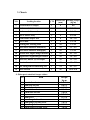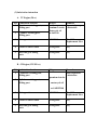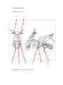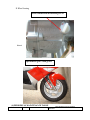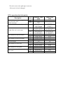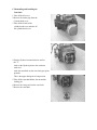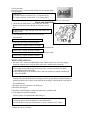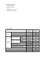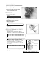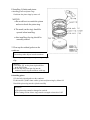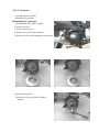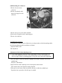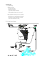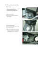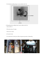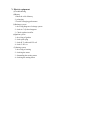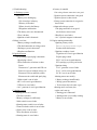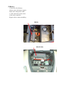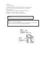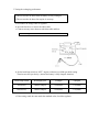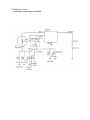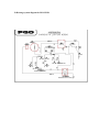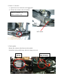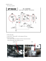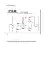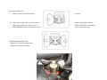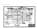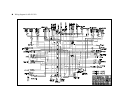
1
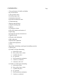
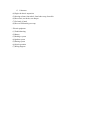
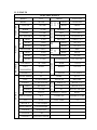
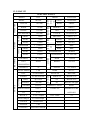
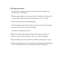
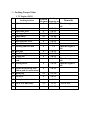
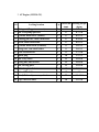
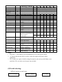
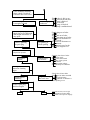
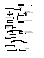
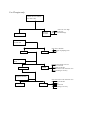
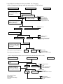
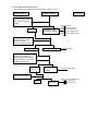
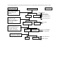
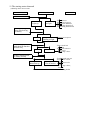
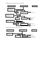
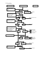
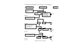
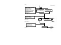
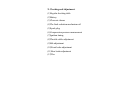
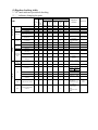
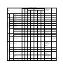
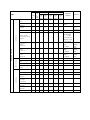
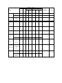
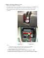
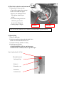
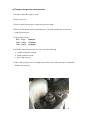
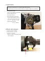
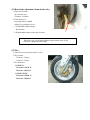
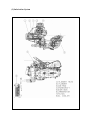
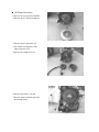
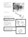
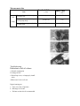
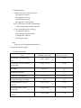
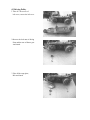
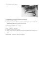
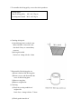
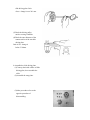
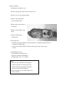
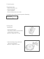
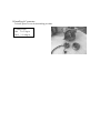
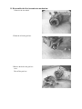
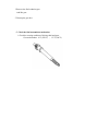
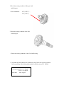
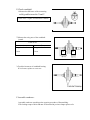
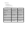
PREFACE
This manual provides every service specialist with professional
techniques of maintenance and repairing for G-MAX (ALLORO). It
provides a detailed guide for those who may concern with how to maintain,
repair, reassemble, and change parts of their scooters.
This manual includes 3 kinds of engine displacement:
G-MAX 50 (ALLORO 50): abbreviated as “M2-50” is 2
stroke engine (2T), 50cc displacement.
G-MAX 125 (ALLORO 125): abbreviated as “M2-125”
is 4 stroke engine (4T), 125cc displacement.
G-MAX 150 (ALLORO 150): abbreviated as “M2-150”
is 4 stroke engine (4T), 150cc displacement.
At every section, we illstrate each important point by assembling
procedures, explosive diagrams and photographs.
Although we have tried our best to make this manual as perfect as
possible, please kindly inform us if any fault needs to be corrected
in this manual.
Thank you for purchasing our PGO scooters.
FACTORY
Motive Power Industry Co.,Ltd.
CONTENTS
.The specification of G-MAX (ALLORO)
.Service information
(1)The operation notice
(2)Locking torque value
(3)Lubrication instruction
(4)Periodical maintenance table
(5)Troubleshooting
.Checking and adjustment
(1)Regular checking table
(2)Battery
(3)Cleaning air cleaner
(4)The final reduction mechanism oil
(5)Spark plug
(6)Compression pressure measurement
(7)Ignition timing
(8)Throttle cables adjustment
(9)Idle adjustment
(10)Front brake adjustment
(11)Rear brake adjustment
(12)Tire
.Dismantling, maintaining, repairing and assembling operation
(1)Plastic parts
(2)G-MAX 50 Engine dismantling
A. Lubrication system
B. Drive pulley, starter, clutch
C. Cylinder and piston
D. AC generator
E. Final transmission mechanism
F. Crankcase, crank shaft
G. Carburetor, reed valve
(3)G-MAX 125/150 Engine dismantling
A. Lubrication system
B. Drive pulley, starter, clutch
C. Cylinder and piston
D. AC generator
E. Final transmission mechanism
F. Crankcase, crank shaft
Page
G. Carburetor
(4)Engine & chassis suspension
(5)Steering column, front wheel, front brake comp, front fork
(6)Rear wheel, rear brake, rear damper
(7)Fuel tank, oil tank
(8)Reverse Differential gear comp
.Electric equipment
(1)Troubleshooting
(2)Battery
(3)Recharge system
(4)Ignition system
(5)Starting system
(6)Switch operation
(7)Wiring diagram
1.1 G-MAX 50
730 mm
HEIGHT
1170 mm
AXLE DISTANCE
1365 mm
FRONT
47 KG
REAR
58 KG
TOTAL
105 KG
PASSENGER
2 (110KG)
FRONT
82 KG
REAR
133 KG
TOTAL
215 KG
TOP SPEED
60 km/hr
TOTAL
45 km/l
CONSUMPTION
ON
FRONT
TELESCOPE
REAR
SWING
PRIMARY
DIRECT
2ND
52/13*44/13
CLUTCH
CENTRIGUAL
SHIFTING
V-BELT C.V.T
FRONT
120/70-12
REAR
130/70-12
FRONT
DISK
REAR
DRUM
SPEEDOMETER
80 km/hr
HEAD(HI LO)
12V-35W/35W
REAR
12V-5W
BRAKE
12V-21W
SIGNAL
12V-10W*4
19°
ENGINE MODEL
P2
HORN
DC 12V
FUEL
92 UNLEADED
SILENCER
DIFFUSER
STROKE
2T AIR FORCED
CYLINDE
GRADIENT
EXHAUS
WEIGHT
PERFORMAN
ENGINE
FUEL
ENSI
WIDTH
KE
1855 mm
SUSP
LENGTH
TRANSMISSI
M2-50D
STEEL PIPE
TIRE
MODEL
FRAME
BRA
PGO
LIGGHT
BRAND
GROSS
DIMENSION
SPECIFICATION
PARTICLE
BELOW 15 %
CO
BELOW 4.5%
HC
BELOW 7000 ppm
BORE
φ40.0 mm
STROKE
39.2 mm
CYLINDER
SINGLE
EXHAUST LAYOUT
RIGHT
DISPLACEMENT
49 cc
LUBRICATE
SEPARATE PUMP
C.R.
6.8 1
FUEL TANK
7.5 L
MAX H..P.
3.5kw/7000rpm
MAX TORQUE
5.0N-M/6500rpm
LAYOUR
HORIZONAL
IGNITION
CDI
STARTING
ELECTRIC & KICK
1.2 G-MAX 125
730 mm
HEIGHT
1170 mm
AXLE DISTANCE
1365 mm
FRONT
54 KG
REAR
76 KG
TOTAL
130 KG
PASSENGER
2 (110KG)
FRONT
94 KG
REAR
146 KG
TOTAL
230 KG
TOP SPEED
84 km/hr
TOTAL
40 km/l
CONSUMPTION
ON
FRONT
TELESCOPE
REAR
SWING
PRIMARY
DIRECT
2ND
43/14*42/13
CLUTCH
CENTRIGUAL
SHIFTING
V-BELT C.V.T
FRONT
120/70-13
REAR
130/70-13
FRONT
DISK
REAR
DISK
SPEEDOMETER
140 km/hr
HEAD(HI LO)
12V-35W/35W
REAR
12V-5W
BRAKE
12V-21W
SIGNAL
12V-10W*4
21°
ENGINE MODEL
C1M
HORN
DC 12V
FUEL
92 UNLEADED
SILENCER
DIFFUSER
STROKE
4T AIR FORCED
CYLINDE
GRADIENT
EXHAUS
WEIGHT
PERFORMAN
ENGINE
FUEL
ENSI
WIDTH
KE
1855 mm
SUSP
LENGTH
TRANSMISSI
M2-50D
STEEL PIPE
TIRE
MODEL
FRAME
BRA
PGO
LIGGHT
BRAND
GROSS
DIMENSION
SPECIFICATION
PARTICLE
BELOW 15 %
CO
BELOW 4.5%
HC
BELOW 7000 ppm
BORE
φ51.5 mm
STROKE
60.0 mm
CYLINDER
SINGLE
EXHAUST LAYOUT
RIGHT
DISPLACEMENT
124.9 cc
LUBRICATE
SEPARATE PUMP
C.R.
9.2 1
MAX H..P.
6.5kw/7500rpm
MAX TORQUE
9.1N-M/6250rpm
LAYOUR
HORIZONAL
IGNITION
CDI
STARTING
ELECTRIC & KICK
& SPLASH
FUEL TANK
7.5 L
1.3 G-MAX 150
730 mm
HEIGHT
1170 mm
AXLE DISTANCE
1365 mm
FRONT
55 KG
REAR
77 KG
TOTAL
132 KG
PASSENGER
2 (110KG)
FRONT
95 KG
REAR
147 KG
TOTAL
242 KG
TOP SPEED
87 km/hr
TOTAL
40 km/l
CONSUMPTION
ON
FRONT
TELESCOPE
REAR
SWING
PRIMARY
DIRECT
2ND
42/15*42/13
CLUTCH
CENTRIGUAL
SHIFTING
V-BELT C.V.T
FRONT
120/70-13
REAR
130/70-13
FRONT
DISK
REAR
DISK
SPEEDOMETER
1400 km/hr
HEAD(HI LO)
12V-35W/35W
REAR
12V-5W
BRAKE
12V-21W
SIGNAL
12V-10W*4
24°
ENGINE MODEL
C5M
HORN
DC 12V
FUEL
92 UNLEADED
SILENCER
DIFFUSER
STROKE
4T AIR FORCED
CYLINDE
GRADIENT
EXHAUS
WEIGHT
PERFORMAN
ENGINE
FUEL
ENSI
WIDTH
KE
1855 mm
SUSP
LENGTH
TRANSMISSI
M2-150
STEEL PIPE
TIRE
MODEL
FRAME
BRA
PGO
LIGGHT
BRAND
GROSS
DIMENSION
SPECIFICATION
PARTICLE
BELOW 15 %
CO
BELOW 4.5%
HC
BELOW 7000 ppm
BORE
φ57.0 mm
STROKE
57.8 mm
CYLINDER
SINGLE
EXHAUST LAYOUT
RIGHT
DISPLACEMENT
147.5 cc
LUBRICATE
SEPARATE PUMP
C.R.
9.4 1
MAX H..P.
7.7kw/7250rpm
MAX TORQUE
10.6N-M/6250rpm
LAYOUR
HORIZONAL
IGNITION
CDI
STARTING
ELECTRIC & KICK
& SPLASH
FUEL TANK
7.5 L
.Service information
(1)The operation notice
(2)Locking torque value
1.For engine
2. For chassis
3. Others
(3) Lubrication instruction
a.For engine
b. For chassis
c. Wheel bearing
(4)Wiring diagram
(5)Troubleshooting
1.Difficult starting or starting
2.Weak acceleration
3.Engine running not smoothly (low speed)
4.Engine running not smoothly(high speed)
5.Clutch, drive & driven pulley
6.Handlebar steering was astray when running
7.Front and rear damper not balanced
8.Brake disorder
9.Oil indicator malfunction
10. Fuel indicator malfunction
11. Starting motor malfunction
12.No sparking
13.Charging abnormal
(1)The operation notice
1.For parts like the gasket, o-ring, clips and circlets, please change a new
part whenever re-assembled.
2.When trying to tighten screws or nuts, please lock tightly according to each
recommended locking torque and in the sequence of the ”X” pattern.
3.Please use PGO or PGO recommended parts.
4.After dismantling, please clean all parts involved or used for checking and
grease all contact surfaces when reassembling.
5.Use grease recommended by P.G.O.
6.When removing the battery, please disconnect the negative pole(-) first.
However, please connect the positive pole(+) first when assembling.
7.Before installing a new fuse, please be sure that the specification is correct.
8.After reassembling, please re-confirm that all connecting point, locking parts,
circuits, polar characteristics are functioning well before selling out.
(2) Locking Torque Value:
1. 2T Engine (50CC)
No
1
2
3
4
5
6
7
8
9
10
11
12
13
14
15
16
Locking
Remarks
Dia (mm) torque kg-m
Cylinder head
7
1.0~1.4 When the engine is
cold
Flywheel outer
10
3.2~4.0
Rear brake lever
6
1.0~1.2
Driving pulley
10
3.2~4.0
Clutch outer
10
3.5~4.0
Right crankcase
6
1.0~1.2
Drive gear box cover
6
1.0~1.2
Left crankcase
6
1.0~1.2
Draining and filler bolt
8
1.8
When the engine is
cold
Inlet pipe
6
1.0~1.2
Flywheel magneto stator
6
1.0~1.2
Cooling fan
6
1.0~1.2
Muffler nut on cylinder
6
1.0~1.2 When the engine is
head
cold
Starting motor
6
1.0~1.4 When the engine is
cold
Bracket between eng. and
6
1.0~1.2
Rubber pad of central stand
Spark plug
14
2.5~3.0
Locking location
Thread
17 Fan cover
6
1.0~1.2
18 Fixed plate, drive clutch
6
1.0~1.4
19 Nut of rear wheel axle
14
11~13
20 Kick starter
6
1.0~1.2
U TYPE NUT
2. 4T Engine (125/150 CC)
NO
Locking location
Q’ty
Thread dia. Locking torque
(mm)
(kg-m)
5
0.7~0.8
6
0.7~1.0
6
0.9~1.1
1 Fixing nut (Tappet screw nut)
2 Nut of oil pump sprocket
3 Cylinder head bolt A (intake)
2
1
2
4 Guiding pin bolt, chain extensioner
1
6
0.4~0.6
5 Screw, chain extensioner
2
6
0.9~1.1
6 Cylinder head bolt B (Exhaust)
2
8
2.0~2.3
7 Flange nut, cam shaft holder
4
8
2.0~2.3
8 Gear oil drain bolt
1
8
1.7~2.0
9 Spark plug
1
10
1.2~1.3
10 Nut of fly wheel
1
12
5.0~6.0
11 Fixing nut, clutch outer
1
12
5.0~6.0
12 Nut, driving plate
1
12
5.0~6.0
13 Bolt of engine oil drain
1
12
2.5~3.0
nd
14 Bolt of 2 oil filter
1
12
0.8
15 Nut (LH thread), one-way clutch
1
22
9.0~10.0
16 Cap, coarse oil filter
1
30
1.5~2.0
3. Chassis
NO
Locking location
Q’TY
Thread dia. Locking torque
(mm)
(kg-m)
6
0.6
1
Air bleed bolt of caliper
1
2
Brake arm bolt, front drum
1
6
0.8~1.0
3
Brake arm bolt , rear drum
1
6
0.8~1.0
4
Nut of starter relay
2
6
0.5~0.6
5
Front brake caliper bolt
2
8
2.0 ~ 3.0
6
Bolt of disk
3
8
2.5~3.0
7
Locking nut, steering stem
1
10
3.5~4.5
8
Rear shock absorber bolt(lower)
1
10
3.5 ~ 4.5
9
Rear shock absorber bolt(upper)
1
10
3.5~4.5
10
Chassis bolt, engine hanger bracket
2
10
4.5 ~ 5.0
11
Engine bolt, engine hanger bracket
1
10
3.0 ~ 4.0
12
Hose bolt, master cyl. & caliper
2
10
2.5 ~ 3.0
13
Front axle nut
1
12
4.5 ~ 5.5
14
Nut, swing arm & connecting rod
1
14
4.5 ~ 5.5
14
Rear axle nut
1
16
10.0~11.0
4. Other parts standard torque values:
No
1
2
3
4
5
6
7
8
9
10
11
Item
5mm bolt and nut
6mm bolt and nut
8mm bolt and nut
10mm bolt and nut
12mm bolt and nut
5mm screw
6mm screw
6mm flange bolt and screw
7mm flange bolt and screw
8mm flange bolt and screw
10mm flange bolt and screw
Torque
kg-m
0.45-0.6
0.8-1.2
1.8-2.5
3.0-4.0
5.0-6.0
0.35-0.5
0.7-1.4
1.0-1.4
1.0-1.4
2.0-3.0
3.0-4.0
(3)Lubrication instruction
A. 2T Engine (50 cc)
NO Lubrication location
1 Crankcase: rotating part,
Sliding part
Oil type
Remarks
Separated-pump
Premium 2 stroke Lubrication
Motorcycle oil
Or SAE#30
2
Cylinder: rotating part,
Sliding part.
3
Drive gear box
SAE85-140
Total 110 c.c.
Replacement 90c.c
4
Gasket of starter shaft
Clean grease
(#3)
5
Start idle gear sliding
parts
Clean grease
(#3)
Oil type
Remarks
Auto-Separated
Lubrication
B. 4T Engine (125/150 cc)
NO Lubrication location
1 Crankcase: rotating part,
Sliding part
premium 4 stroke
2
Cylinder: rotating part,
Sliding part.
motorcycle oil
or SAE15W40
3
Drive gear box
SAE85-140
Total 110 c.c.
Replacement 90c.c
4
Gasket of starter shaft
Clean grease
(#3)
5
Start idle gear sliding
parts
Clean grease
(#3)
C. Chassis appearance
1. Apply oil : #1, #2
1
3
2
4
5
6
2. Apply grease (#3, #4, #5. #6 ,#7, #8)
7
8
D.Wheel bearing
Final transmission mechanism gear oil
Error!
Speedometer gear: clean grease
(4)PERIODICAL MAINTENANCE TABLE
Model
MONTHS/DISTANCE(IN KM)FOR
CHECKING
Item
2T or 4T
Engine oil
Engine oil*
Oil Filter
Coarse oil filter* (on oil
draining bolt)
Air cleaner
Air filter
Gear oil*
Disk & drum brake
Clutch shoes*
Rear brake arm
Tires
2T
4T
ALL
4T
ALL
ALL
ALL
ALL
ALL
ALL
ALL
Wheel bearing*
Front fork*
Steering head bearing*
ALL
ALL
ALL
Rear absorber*
Main/Side Stand
ALL
ALL
Nuts, bolts, fasteners
Battery
ALL
ALL
Valve gap*
4T
Carbon cleaning *
2T
Spark plug*
V belt*
ALL
ALL
Fuel feeding system*
ALL
Engine idle speed*
ALL
Carburetor idle A/F
Adjustment*
ALL
Add
Replace (800cc, total 900cc)
Replace
○
○
6 or
9 or 12 or 15 or 18 or
5000k 8000k 10000k 13000k 15000k
According to Oil warning light
Replace it per 1000km
Clean it per 5000km or replace it if required
Clean or replace it if necessary
○
Clean it per 3000km or replace it if required
Checking Content
Clean or replace it if necessary
Clean or replace it if required
Replace (90cc, total 110 cc)
Leaking and function check
Check or replace it if necessary
Function check and adjustment
Worn-out check or replace it if
necessary
Fasten tightly if loosen
Leaking and function check
Check looseness. Adjust it if
required
Leaking and function check
Function check or replace it if
required
Tighten it if required
Make sure that the voltage
stayed over 12.8V. Recharge the
battery it required.
Clear the poles.
Check and adjust when engine
is cool (0.08mm for IN & EX)
Clean combustion carbon when
engine output reduced
Clear or replace if required
Worn out check or replace if
necessary.
Crack and blockage check.
Replace it if necessary.
2T engine: 1900±100 rpm
4T engine: 1700±100 rpm
Check and adjust referring to
CO/HC Percentage.
1 or
300 km
○
3 or
3000k
○
○
○
○
○
○
○
○
○
○
○
○
○
○
○
○
○
○
○
○
○
○
○
○
○
○
○
○
○
○
○
○
○
○
○
○
○
○
○
○
○
○
○
○
○
○
○
○
○
○
○
○
○
○
○
○
○
○
○
○
○
○
○
○
○
○
○
○
○
○
○
○
○
○
○
○
○
○
○
○
Adjust it when necessary
○
○
○
○
○
○
○
○
○
○
○
○
○
○
○
○
○
○
○
○
○
○
○
○
○
○
○
○
○
NOTE
1. Items with “*” mark indicate our recommendation to have it done by PGO dealer.
2. “A” denotes that function check or replace it when the engine performance reduces
significantly.
3. For 4T engine, the engine oil shall be changed completely after run-in period 300km or one
month later. This can make sure the engine runs smoothly.
(5)Trouble shooting:
1.difficult starting or can’t start:
Check and adjust
○
○
Trouble condition
The reason
Loose carburetor draining
Screw, check if in side of
Carburetor have fuel or not
The fuel supply in carburetors
Is enough or smooth
check there is fuel or not
pipe between ful tank and
No fuel supply in carburetor is blocked
Float is blocked
carburetor
Fuel gauge is blocked
fuel pump is malfunctioned
Remove spark plug, insert
Spark plug cover, and touch
With engine check there is
Any spark
There is sparking
In spark plug
No sparking or
Weak sparking
spark plug out of order
dirty
CDI unit out of order
A.C. generator out of order
ignition coil disconnect or
short circuit
ignition coil disconnect or
short circuit
main switch out of order
defective magneto coil
Measurement of
Compression pressure
Pressure is
normal
Insufficient or
No Pressure
starting clutch out of order
piston ring stuck
reed valve deteriorated
cylinder, piston, piston
ring worn out
cylinder gasket leakage
cylinder body has sand hole
Start engine: follow the
Instruction of starting
engine
Engine has no
knocking
bad action of auto choke
air trapped in intake manifold
Engine knocking wrong ignition timing
But can’t start
bad adjustment of carburetor’s
fuel adjusting screw
Remove spark plug
And check again
dry
wet
carburetor fuel level too high
malfunction of auto choke
throttle valve open too largely
2.Weak acceleration:
Trouble condition
Check and Adjust
The reason
Start engine and open throttle
Gradually, check and inspect
Engine can rotate up
Engine can’t rotate
Up completely
air cleaner blocked
fuel supply system abnormal
fuel tank cover blocked
muffler blocked
fuel pump is malfunctioned
auto chock is malfunctioned
Timing is not correct
CDI unit is out of order
alternator flywheel magneto
out of order
Check ignition timing, check
With ignition timing lamp
Timing is correct
Check cylinder
Compression pressure
(use cylinder compression
pressure gauge)
Pressure is
Not normal
Pressure is normal
cylinder, piston ring worn out
cylinder gasket leakage
cylinder body has sand hole
Reed valve malfunction(2T engine)
Check carburetor
Is blocked or not
No blocked
blocked
Clean the carburetor
Remove spark plug and Check it
No dirty and no color change
Dirty, color change
clean the dirt
specification is not correct
For 4T engine only:
Check the oil level in crankcase
Is too much or dirty
Oil level is normal
Oil level is
Not normal
oil level is too high
oil level is too low
oil does not interchange
Check the lubrication
of cylinder head
Normal
Abnormal
oil route is blocked
insufficient oil pumping from
oil pump
Check engine overheat
Or not
Not overheat
overheat
piston and cylinder worn out
mixture is too lean
bad quality of the fuel
too much carbon in the combustion room
ignition timing is too early
Running accelerately or
High speed continuously
No knocking
knocking
too much carbon in the combustion room
bad quality of the fuel
clutch slip
mixture is too lean
ignition timing is too early
3.Engine running unsmoothly (low speed and idling)
Check and adjust
Trouble condition
The reason
Check ignition timing
Correct
Not correct
CDI faulty
AC generator faulty
Adjust carburetor air screw
Good
adjustment
mixture too thick
Faulty
( loose the screw)
Not correct mixture too lean
( tight the screw)
Check if there is air
Leakage on carburetor
gasket
No leakage
Remove spark plug, insert
To spark plug cover and
Connect with ground
Start engine, then check
The sparking
Good sparking
heat protector gasket broke
carburetor locking nut loosen
leakage gasket crack
hose leakage
lntake manifold gasket broken
Carburetor O ring distorted
Sparking abnormal
Or no sparking
spark plug dirty
CDI out of order
AC magnet abnormal
ignition coil faulty
H.V. coil disconnect or
short circuit
main switch is abnormal
Check generator
good
fault
A.C. generator malfanction
hose is damaged
air pipe is blocked or
damaged
4.Engine running unsmoothly (high speed)
Check and adjust
Trouble condition
The reason
Check ignition
timing
correct
Not correct
CDI sets faulty
AC generator faulty
Check fuel pump,
Fuel supply system
good
unsmoothly
fuel level is too low
fuel pipe, fuel filter
is blocked
fuel pump faulty
Check carburetor
Is blocked or not
No blocked
blocked
clean and wash it
5.Clutch, drive and driven pulley
Trouble condition
Engine can start but can’t
Move the vehicle
Engine runs, but it stops
Suddenly and seems to rush out
(rear wheel rotates while idling)
Climbing is not smoothly
The reason
driving belt worn out, distortion
driven plate worn-out
driven plate spring distorted
driven lining worn-out
driving pulley shaft gear teeth
cracked
final gear damage
driven lining spring cracked or
worn out
weight rollers melt and stick to
driving face
shaft worn-out
driving belt worn-out, distorted,
or slipping
weight roller worn-out
driving plate worn-out
driving plate spring distorted
driving pulley shaft worn-out
Can’t reach high speed
driving belt worn-out or slipping
weight roller worn-out
driving pulley shaft worn-out
Noise, or bad smell when
running
adherent grease on driving belt,
pulley
driving belt worn-out
driven plate spring distorted
driving pulley shaft worn-out
6.Handlebar steering astrayed when running.
Trouble condition
Handlebar operates heavily
Front and rear wheel swings
Handlebar astrayed to one direction
The reason
(front and rear wheel pressure are normal)
steering column lock screw locked too
tightly
steel ball cracked
rear, front wheel bearing swings
front, rear wheel rim distorted
loosen front axle nut
front and rear wheel center not welldigned
front fork crooked
7.Front, rear damper not in balanced
Trouble condition
The reason
(front and rear wheel pressure is normal)
Damper is too soft
damper spring is too soft
carrying weight is too large
damper oil leakage
Damper is too hard
front fork guide rod crooked
damper and damper cover cracked
Damper has abnormal noise
problems in damper tube and spring
damper and damper cover cracked
8.Brake disorder.
Trouble condition
The reason
(adjustment according to standard procedure)
Brake plate” ”mark
points to “ ”mark
Noise when brake
Faulty performance
brake lining worn-out
bake lining cam worn-out
brake cam worn-out
brake hub worn-out
brake lining worn-out
unknow matenals attached on brake lining
Contact surface of the wheel hub becomes
rough
brake cable over stretching or moving
unsmoothly
brake contacting surface wi6h brake lining does
not comtact 100%
water or sand drop into brake mechanism
some grease on brake lining surface
9.Oil indicator malfunction (Only available for 2T engine)
(a)The oil lamp doesn’t light up, (when the main switch is at “ON”position)
Check and adjust
Trouble condition
The reason
Turn the signal lamp
On. Check wiring
Of battey
Normal
fuse burn-out
Lamp dims, light does battery has no power
main switch abnormal
Not flash, no light
circuit plug dropped off
main wiring disconnected
Remove the oil lamp,
And connect with
Battery directly
Lamp lights
Lamp does not light up
bulb burn out
Check electric plug
Good condition
electric plug is loose
or disconnected
main wiring disconnected
wrong wiring connection
No good
Remove oil gauge,
Check the lamp light
Up or not by moving
The float
Float upward: lamp Extinguishes
Good
No good
Float downward: lamp turn on
float faulty
oil gauge switch disconnected or short circuit
(b)Oil is enough but the indicator turns on all the time (when the main switch is “ON”)
Check and adjust
Trouble condition
The reason
Check all electric
plug
Good
Disorder
Good
Disorder
Remove oil gauge,
Check the lamp by
Moving the floating
Float upward: lamp
Extinguishes
Float downward: lamp
Turns on
electric plug is loose
or drop-off
main wiring disconnected
wrong wire connection
float faulty
oil gauge switch
disconnected or short circuit
oil tank distorted
some impure material
dropping in
10.Fuel indication malfunction
(a)wrong fuel level indication(when the main switch is “ON”)
Check and adjust
Trouble condition
The reason
Turn the signal lamp
On; check wiring of
battery
normal
Lamp dims, light
Not flash, not light
fuse burn-out
battery has no power
main switch abnormal
circuit plug dropped off
main wiring disconnected
Remove the fuel gauge
Moving float up and
Down to check
The needle movement
Indicator moves
Indicator no motion
Float abnormal
Do the short and opening
Circuit test on the fuel
Gauge plug which connect
To wire harness. Check the
indicator movement
Indicator
moves
Indicator on
motion
Fuel gauge abnormal
Check electric plug
good
abnormal
electric plug dropped off
wrong connection
wire broken or short
circuit
(b)Fuel gauge needle is not steady and sometimes moves up and down (when the main switch is “ON”)
Check and adjust
Trouble condition
Turn signal lamp on,
Check wiring of
battery
normal
Remove the float
Inside the tank,
Move up and down to
Check the needle’s
movement
Move needle up and
Down quickly(I move/
Second), check the
Needle’s movement
Indicator moves
good
Indicator
moves
The reason
fuse burn-out
battery has no power
main switch abnormal
No motioncircuit plug dropped off or
broken
main wiring disconnected
No
fuel gauge contact
movement
abnormal
Indicator no
movement
Insufficient or no damping
Oil inside the fuel gauge
Check electric plug
Connecting condition
good
abnormal
electric plug drop-off or
loose
wire broken or short
circuit
11.The starting motor abnormal
(a)Starting motor can not rotate
Check and adjust
Trouble condition
The reason
Check brake switch
Brake lamp
Lights up
Brake lamp
no light
Turn signal lamp
No to check wiring
Of battery
normal
Lamp does not
Flashing no light
Push starting switch
And check the function
Of start relay
normal
No function
fuse burn-out
battery has no power
main switch abnormal
circuit plug dropped off
main wiring disconnected
battery has no power
start switch bad
connetion
relay wire broken or
short circuit
circuit plug is loose
Connect starting motor
To battery directly
Starting
Motor runs up
Starting motor
Has no motion
carbon brush worn out
coil broken or short
circuit
starting motor wire
broken
circuit plug is loose,
drop-off
main wiring broken
(b)Starting motor running slowly or no pick-up
Check and adjust
Trouble condition
The reason
Turn signal lamp
On, to check wiring of battery
normal
Lamp dims, no
Flashing, no light
battery has no power
Runing slowly
electric; plug is loose
or drop off
start relay bad
connection
Starting Connect motor
to the starting motor to
Battery directly
Running
normal
Kick the kickstarter
lever
Easy to kick
Difficult to kick
cylinder burn out
wire broken or shout
circuit
©Starting motor can not stop after starting
Check and adjust
Trouble condition
The reason
Main switch,
Turn off
Motor can’t
stop
Motor stops
start gear can’t
return
start relay capacitor
melted or short circuit
12.No sparking
Check and adjust
Trouble condition
The reason
Replace new spark
Plug, then check
again
Good sparking
Weak sparking
Spark plug faulty
Or no sparking
Check spark plug, cap
And H.V. cable is
Loose or not
good
loosen
Spark plug cap is loose
loosen
Plug is poor
connection
Check the CDI plug
Is loose or not
good
Check the connection
Between CDI plug and
Each terminals, check
The resistivity of
Each terminals
good
abnormal
min switch faulty
defective magneto
coil
pulse generator faulty
defective ignition
coil
Check relative parts
good
good
abnormal
abnormal
main cable broke
poor connection of
joints or sockets
defective CDI
Check ignition coil
By the CDI tester
abnormal
Defective ignition
coil
13.Charging abnormal(battery over charging or over discharging)
Check and adjust
Trouble condition
The reason
Measure battery’s
Voltage then start
engine
Voltage remain
The same
malfunction
Voltage goes up
To normal value, battery is dead
But after engine battery
Stop, the voltage
Goes down again
Check voltage rectifier
Plug is loose or not
good
loosen
connection
poor
red cable
Check the voltage
disconnected
Between chassisΘand
The red cable of
Voltage rectifier
rectifier
good
No voltage
voltage
malfunction
white cable
disconnect
Check the resistivity
Of A.C. generator coil
normal
abnormal
connection
defective coil
poor
A.C.
generator’s
charging abnormal (over charging)
white
cable
disconnected
Start engine, connect
green cable to
Chassis, then
measure the voltage
between chassisΘ
and red cable of
voltage of
rectifier
Voltage higher
Than specification
Voltage normal
Check the connection
Of the cable of
Voltage rectifier
connection
good
cable poor
Poor connection
poor
connection of
green cable
Check the resistivity
Of the body of
Voltage rectifier
Out of spec
Voltage
rectifier
faulty
3. Checking and Adjustment:
(1)Regular checking table
(2)Battery
(3)Clean air cleaner
(4)The final reduction mechanism oil
(5)Spark plug
(6)Compression pressure measurement
(7)Ignition timing
(8)Throttle cables adjustment
(9)Idle adjustment
(10)Front brake adjustment
(11)Rear brake adjustment
(12)Tire
(1)Regular checking table:
1. O mark indicates periodical checking
2.
indicates changing the parts
Checking period
first
home
month every6 every12
l
every1
or
months months
months
che-cki
Initial
or
or
or
ng
300km 5000km 10000km 1000km
gen-era
Item
Suspension
Handlebar
steering
column
front fork
Loose or swing
Operation
Turning angle
Damaged
○
○
○
○
Shaft fixed condition
Lever
Brake cable
Brake
Brake cam
Wheel hub
and brake
shor
○
b. movement of brake
loose or damage
Change brake cable
worn out
a. clearance between hub
and lining
b. brake shoe and brake
lining worn-out
○
○
○
every3
every12
months
months
or
or
2500km 10000km
○
○
○
○
○
○
○
○
○
○
○
○
○
○
○
○
○
○
○
○
○
○
○
○
○
○
○
○
○
○
○
○
○
○
○
○
○
Shaft:loose
a. clearance
office
Judgement
standard
Check from
Stering column
Check from
Stering column
○
Clearance:
Front:10-20mm
Rear :
every 2 ears
○
○
○
○
○
c. wheel hub worn and
damaged
○
○
○
○
○
○
Front wheel
damaged or distorsion
axle
Rear wheel
damaged or distorsion
axle
standard
dia:rear:110.0mm
limit of
use:rear:111.0mm
○
○
Pressure
○
Cracked or damaged
○
○
○
○
○
○
○
○
○
○
○
○
tire thread worn out
○
○
○
○
○
○
tire surface or other
intruders
○
○
○
○
○
○
unit: kg/c ;1 driver
front tire rear tire
2.0
tire
Remark
Wheel
Axle
Tighten the bolt and nut
○
○
○
○
○
Rim
swingness and damage
condition
○
○
○
○
○
Change tire
according to
2.0
mark
Front axle nut torque
5.0-6.0kg-m
rear axle nut torque
11.0-13.0kg-m
Swingness limit
Vertical: below
2.0mm
Horizontal: below
2.0mm
Nut
location
Checking period
first
home
month every6 every12
l
every1
months months
months
chec-ki or
Initial
or
or
or
ng
300km 5000km 10000km 1000km
gen-era
Item
wheel
Bearing
Spring
Ass’y part
Clearance on
Front axle
Clearance on
rear axle
Damage
Condition
Loose
or
condition
○
Rear Damper
Transmission
Ignition
○
○
every3
every12
months
months
or
or
2500km 10000km
○
○
○
damaged
Connecting
loose or
part
loose or damage
Bracket
condition
Looseness on
Suspension
Connecting
arm
Part
Oil leakage
Damaged
Absorber Condition
Loose on ass’y
part
Clutch and Function
Shift mec- Gear oil
hanism leakage
Gear oil
○
office
Change gear oil
Spark plug
Electric
Start
Starting motor
Mechanism gear
Recharge
Wiring
Function
Electrolyte
level
○
○
○
○
○
○
○
○
○
○
○
○
○
○
○
○
○
○
○
○
○
○
○
○
○
○
○
○
○
○
○
○
○
○
○
○
LH crank
case
○
○
○
○
○
90C.C. / replace
110C.C/ total
○
○
○
○
○
○
○
○
Clearance:
0.6~0.7mm
NCK:BP7HS
OR SAME
SPEC
○
○
○
○
○
○
○
○
○
○
Level between
“UPPER” and
“LOWER”
○
○
When 20
Specific gravity:
1.270-1.290
○
○
Electrolyte
gravity
Looseness or Damage
on connection plug
Remark
○
Battery
Wire
circuit
Judgement
standard
○
○
○
○
Checking period
first
home
month every6 every12
l
every1
months months
months
che-cki or
Initial
or
or
or
ng
300km 5000km 10000km 1000km
gen-era
Item
office
every3
every12
months
months
or
or
2500km 10000km
Performance,
Noise
○
○
○
○
Low speed,
Acceleration
○
○
○
○
○
Air cleaner
○
Idling: 1900±
○
○
○
○
○
○
○
○
○
○
○
Engine parts
Cylinder, cy1inder
head, inlet pipe, locking
Condition
○
Lubrication system
Engine mechanism
Compression
Pressure
(G-MAX 50)
○
○
Compression
Pressure
G-MAX 125
○
○
Compression
Pressure
G-MAX 150
○
○
○
Oil leakage
Oil quantity,
Dirty
○
○
○
Locking torque
Cylinder head:
(cold)
1.0-1.2KG-m
inlet pipe: cold)
1.0-1.2kg-m
.
6kg/c
@ 600rpm
.
12kg/c
@ 750rpm
.
11kg/c
@ 650rpm
○
○
○
○
○
○
○
○
○
○
Fuel system
Fuel leakage
○
○
Clean
Carburetor
○
○
Carburetor’s
Throttle and
Choke function
○
○
Carburetor
Float height
○
Carburetor
Adjustment
○
Change fuel pipe
○
Check the
color of
exhausting-air
○
Oil filter
blocked
Fuel quantity
Remark
100rpm
Exhaustion
Oil quantity,
Judgement
standard
○
○
○
○
○
○
○
○
○
○
○
○
○
○
○
○
○
every 4 years
Using
starting
motor
Using
starting
motor
Using
starting
motor
Checking period
first
home
month every6 every12
l
every1
months months
months
che-cki or
Initial
or
or
or
ng
300km 5000km 10000km 1000km
gen-era
Item
Function
Lamp system
Dirty or broken
Horn, signal
Function
office
every3
every12
months
months
or
or
2500km 10000km
○
○
○
○
○
○
○
○
○
○
○
○
○
○
○
○
○
○
○
○
○
○
○
○
○
○
○
○
○
○
○
○
○
○
○
○
○
○
○
○
○
○
○
○
○
○
Lamp, reflector
lock
Rear view
Function
Dirty or broken
○
License plate
Dirty or damaged
○
Dashboard
Function
○
mirror
Muffler
silencer
Losseness or
Damage on
Ass’y part
Function
Loose or
chassis
Damaged
The previous
Abnormal case
Confirm it does
Not happen
Again
Chassis
others
○
○
○
○
Lubrication
Decarbonate on
Combustion room
And muffler
○
○
Judgement
standard
Remark
(2)Battery: Recharge when power is out
1.Remove the rear luggage cover by hand.
2.Screwing out the two screws on the battery cover. Remove the battery cover. (G-MAX125/150)
3.Remove the negative cable and then the positive cable,→take out the battery to recharge.
4.To re-assemble the battery, please follow the opposite procedure of disassembling after
recharging.
Positive Pole
Negative Pole
Note:
A. The battery is totally sealed, do not remove seal bolts when recharging
B. It’s no need to add any electrolyte for this re-filling free battery
Please recharging (12V) by the following currency
G-MAX50: Standard recharging:0.4A* 5-10 hr or rapid recharging:3A* 30min.
G-MAX125/150: Standard recharging:0.7A* 5-10 hr or rapid recharging:3A* 30min.
(3)Cleaning air cleaner
1.Remove air cleaner cover
2.Take out the air cleaner filter
G-MAX50
G-MAX125/150
3.Clean the filter by the compressor air.
4.Assemble the air cleaner by the opposite procedure.
Note: Do not start the engine When the air cleaner is Not installed
(4)The final reduction mechanism oil
1.Change the oil in the gear box:
a. Turn off the engine after warm up.
b. Put a bowl under the engine.
c. Remove the draining bolt and
Filler bolt to drain the gear
oil off.
d. Lock the draining bolt before
refill 90c.c gear oil and
then lock the filling bolt.
e. Locking torque: 1.8kg-m
Draining
Filling Bolt
Note: Be sure the crankcase, tire or wheel are cleaned if there is grease/oil on it
(5)Spark plug
1.Remove spark plug
2.Check the spark plug electrode and check if it is
Burnt out or not and carbonized or not
3.Clean the electrode, whether it is dirty
4.Spark plug specification
G-MAX50: BP7HS (NGK) or equivalent spec.
G-MAX125/150: C7HSA (NGK) or equivalent spec.
Gap of spark plug:0.6~0.7mm
Electrode burn out/
Carbon piled up
Washer is
Distorted or not
Procelain is
Cracked or not
(6)Compression pressure measurement:
1.Measure it when the engine is warm.
2.Remove the cover.
3.Remove spark plug then place compression pressure gauge.
4.Fully open the throttle, and using starting motor 5 seconds continuously, measure the
compression pressure.
5.Compression pressure:
50cc: 6 kg/c
125cc: 12 kg/c
150cc: 11 kg/c
@600rpm
@750rpm
@650rpm
6.when the compression pressure is too low, check the following:
a. cylinder head gasket cracked.
b. piston cylinder worn out.
c. piston ring worn out.
7.If the compression pressure is too high it may be due to the carbon piled up on combustion
chamber and piston tip.
(7) Ignition timing:
This scooter is using CDI set, it is no need to adjust ignition timing.
If ignition timing is not correct, check the CDI sets AC magneto, change it if it is abnormal.
checking ignition timing:
1.remove seat the luggage compartment
2.Remove right body cover
3.Remove the fan case.
4.Check with ignition timing lamp.
keep the engine running at 1,900 ±
100 r.p.m the checking mark should
lay in ±30 apart From “F”, mark.
5.ignition timing: B.T.D.C.
17° ±3° / 1900rpm
(8)Throttle cables adjustment:
1.check the clearance of throttle.
2.Normal clearance:1.5-3.5mm
3.Adjust it by rotating the
adjust nut ; change it if the throttle cables
can’t be adjusted.
(9) Idle adjustment:
Note: adjust it when the engine is warm.
1.remove left body cover
2.start the engine and connect the tachometer
3.adjust the throttle valve screw
to the specified revolution 1900±100rpm.
4.if the idling rpm is still unsteady or
fuel up is not smooth, please adjust it by
followings.
a. Screw in the air adjust screw clockwise,
then screw out counterclockwise.
Recommended loop: 1 3/8×1/2
b. Rotate air adjust screw clockwise and counterclockwise to find out the highest
revolution location.
c. Rotate the throttle valve screw to idling condition.
d. Fuel up gradually until the idling running rpm is steady.
e. If the rpm is still not steady please repeat above procedure.
(10)front brake adjustment:
1.check the clearance of front brake lever.
Clearance:10-20mm
2.if the clearance is beyond, standard check whether:
a. The air mix into the pipe/caliper.
b. The oil brake system is leaking.
Note:
Try brake lever to see if it’s loose.
Check the brake fluid. Once air mixed in
The fluid pipe, which will reduce or
Damage the brake efficiency or even its
Function.
3.check the fluid level:
a. Refill the brake fluid when the level is under the LOWER line.
b. Brake fluid specification: SAE J-1703F-DOT3&DOT4.
Note:
a. To prevent the fluid splitting onto the parts or clothes, put a piece of cloth on
the bottom when refilling.
b. Be caution not to mix water or particles into the master cylinder when refilling.
c. Never use the fluid not complied with spec.
d. In case the fluid stains on the eyes, wash with water at once and then ask for
medical care immediately.
(11)Rear brake adjustment (drum brake only)
1.Check the clearance
Of rear brake lever.
Clearance: 10-20mm
2.If the clearance is
beyond the above standard,
Adjust it by rotating the screw.
a. Left-handed rotation-enlarge
the clearance.
b. Right-handed rotation-reduce the clearance.
Note:
When the arrow of rear brake indicator align with the arrow of left
crankcase, change the brake lining.
(12)Tire:
1.Check the tire air pressure(when it’s cold)
2.Tire pressure:
Front tire: 2.0 kg/c
Front tire: 2.0 kg/c
3.Tire dimension:
G-MAX 50:
Front tire: 120/70-12
Rear tire: 130/70-12
G-MAX 125/150:
Front tire: 120/60-13
Rear tire: 130/60-13
Note:
a. Check and adjust the tire pressure when it is too low.
The pressure is according to the carrier, Driver, passenger, accessories and cruise Speed.
b. Proper loading is very important for steering, riding, braking, performance and safety.
c. Never carry any parcel unfastened.
d. Load the heaviest parcel on the center of vehicle, balancing the weight on both sides.
e. Beware of the weight loaded properly and check the tire pressure. The total weight
of carrier, driver, passenger, and accessories cannot exceed the approved
limit, An overload vehicle is easy to cause tire damage and accident for rider.
4.Check is there any sharp Object pierce the tire.
5.Check the depth of tire Thread.
a. Depth(front & rear):
According to mark of tire “▲”to change a new tire
4. G-MAX 125/150 engine Dismantling, Maintaining, Repairing and assembling operation
(1) Lubrication system
(2) Engine dismantling
(3) Drive pulley, starter, clutch, driven pulley
(4) Cylinder head and valve
(5) Cylinder and piston
(6) AC generator
(7) Final transmission mechanism
(8) Crankcase, crank shaft
(9) Carburetor
(1)Lubrication System
Oil Pump Dismantling
1.Remove the rear section of muffler.
2.Remove the AC flywheel magneto.
3.Remove the AC generator coil.
4.Tale off the locking bolts of the
right crankcase cover.
5.Remove the crankcase cover
6.Remove the washer, lock pin
7.Remove starter reduction gear and
the starting clutch.
8.Remove oil pump separate plate by
taking off the 2 bolts.
9.Remove the bolts from oil pump
driving gear
10.Take off the driving gear and chain.
11.Remove the oil pump by taking off
the locking bolt of the oil pump.
Oil pump Assembly
1.Install the inner and outer of the oil pump.
2.Install the oil pump shaft.
Note:
The notch of the oil pump shaft should comply
With the notch of the inner gear.
3.Install the lock pin.
4.Match the lock pin hole to the pump cover
and install the oil pump cover.
5.Put on the screws and tighten them.
6.After installing, turn the shaft lightly
to assure installation.
7.Place the oil pump into the crankcase.
Note:
When installing, the arrow on the oil pump
body should be pointed upwards. Then fill in
the recommended oil before the installation.
8.Tighten the oil pump after installation.
Measurement data
item
Oil
pump
Standard Value
( mm )
Limit of use
( mm )
Clearance between the inner gear
And outer gear
_
0.12
Clearance between the outer gear
And oil pump body
0.045-0.10
0.12
Clearance between gear end and
Oil pump body
0.045-0.10
0.12
Troubleshooting
Reduction in fuel oil volume
a. Natural consumption
b Leakage of fuel
c.Piston loop seizes, or improperly installation
d.Worn out of valve’s oil seal
Engine burning-out
a. Zero or too low oil pressure
b. Blockage in oil route
c. Did not use the fuel oil recommended
A.Dismantling engine
1.Take off the luggage compartment.
2.Take off the left and right body
covers.
3.Take off the air cleaner fixing screws.
4.Loosen 2 nuts of intake manifold, withdraw
intake system assembly.
5.Remove vacuum pipe, fuel pipe ,auto
choke, cap of spark plug, rear
brake cable carburetor pipe, starter motor cable.
6.Remove the rear section of muffler, dismantle
the 2 bolts of rear brake caliper, then remove the
rear brake system assembly away from rear fork.
7.Loosen bolts of upper & lower engine hanger.
8.Remove the engine.
B.Installing Engine
1.To install engine, please reverse the
Above procedures.
2.Locking torque:
M8:
2.0-3.0kgf.m
M10:
3.0-4.0kgf.m
M12:
5.0-6.0kgf.m
3.After installing, pleas do the following
Checking and adjustment:
a. Wiring for each circuit.
b. Throttle cable
c. Rear brake check.
d. fuel and oil route
(2)Drive pulley, starter clutch. driven
pulley
A. Troubleshooting
B. Measurement data
C. Driving pulley
D .Starter
E. Clutch driven pulley
A.Troubleshooting:
a.Engine starts, but vehicle don’t move.
1.driving belt worn out
2.driving plate worn out
3.clutch lining worn out
4.driving plate’s spring broken
b.the vehicle stops or tremble when running.
1.clutch lining spring cracked or broken.
c.Can’t reach high speed, no pick-up
1.driving belt worn out.
2.Driving plate spring distortion.
3.Weight roller worn out
4.Driving plate dirty.
Note:
No grease and oil should be distributed over
driving belt and driving plate.
B. Measurement data
Item
The inner dia. Of slide driving
plate
The outer dia. Of boss, movable
Standard value ( mm )
24.011~24.052
23.960.~23.974
Limit of use ( mm )
24.10
23.940
Driving plate
Belt width
Clutch lining thickness
Clutch outer inner diameter
Driven plate spring, free length
The outer diameter of driven
20.0~21.0
3
19.0
1.5
125.0~125.2
125.5
151
127
33.965~34.025
33.95
34.000~34.025
34.06
17.920~18.080
17.40
Plate sets
The inner diameter of slide
Driven plate
The outer diameter of weight
Roller set
(C)Driving Pulley
1.Take off the screws of
left cover, remove the left cover.
2.Remove the lock nuts of driving
Plate and the nuts of Starter gear
And clutch.
3.Take off the ramp plate,
Belt and clutch.
4.Take off the boss and driving plate.
5.Continuous Various Transmission engagement speed inspection
Connect an electric tachometer.
Seated on the motorcycle with on level ground, increase the engine’s speed slowly and notice
the RPM at which the motorcycle begins to move forward.
Specified Engagement RPM : 3100 ± 300 rpm
6.Clutch “LOCK-UP” inspection
Apply the rear brake as firm as possible
Briefly open the throttle fully and notice the maximum engine RPM sustained during the test
cycle.
Specified Clutch “LOCK-UP” RPM : 5200 ± 400 rpm
5.To assemble the driving pulley, reverse the whole procdeure.
Locking torque:
1.Nut of driving pulley M12: 4.0-5.5kg/m.
2.Locking nut of clutch M12: 4.0-5.5kg/m
6.Checking driving belt
(1)check driving belt is cracked or not
rubber and fiber is loosened or not
also check if they are extraordinary
worn out.
(2)driving belt width:
limit of use :change it below 19mm
7.Disassemble slide driving plate set.
(1)Remove bush of slide driving plate.
(2)Remove screw, and disassemble the
cover of slide driving plate.
(3)Remove ramp plate.
(4)Remove weight roller.
8.Checlomg
(1)Check the wearing condition of
weight roller.
Limit of use : change it below 17.4mm
(2)Check gasket inner dia of
slide driving plate: limit
of use : change it over 24.1mm.
(3)Check the driving pulley
surface wearing condition.
(4)Check the outer diameter of the
contact surface of the movable
driving plate.
limit of use : change it
below 23.94mm.
9.Assemble the slide driving plate.
(1)Clean up the inside surface of slide
driving plate, then assemble the
roller.
(2)Assemble the ramp plate.
(3)Other procedure refers to the
opposite procedure of
disassembling.
D.Starter dismantle
1.Dismantle left crankcase cover
2.Remove hexagon nut, then remove the starter lever.
3.Remove five screw of separated plate.
4.Remove start spring from
start returning position.
5.Remove driven gear comp. of
kick starter.
6.Remove the retaining C-type
Ring.
7.Remove spindle comp.
of kick starter.
8.Checking starter
a. Check the wearing condition of the outer diameter of spindle comp and the inner
diameter of bush and gear.
b. Check the wearing condition of shaft of driven gear comp. Gear sets and
ratchet.
9.Assembling the starter
Assemble the starter follows the.
Opposite procedure of dismantling.
Locking torque : M6: 1.0~1.2kg/m.
Note:
Make sure one end of the torsion spring is
hooked on the groove of driven gear, and
another end of torsion spring is hooked on
the pole of inside of left crankcase.
Put some grease in every shaft and gear sets
before assembly.
E. Clutch driven pulley
1.Dismantling the clutch
a. Remove left crankcase cover.
b. Remove driving plate.
c. Remove driving belt.
d. Remove locking nut, then remove clutch.
2.Assemble the clutch : follows the opposite procedure of dismantling.
Locking torque:
M12: 4.0~5.5kg.m
3.Checking clutch:
dismantling tool
a.Check clutch driving face.
Check clutch cover about its wearing condition
And inner diameter measurement.
limit
of use: change it above 125.5mm
b.Check clutch lining wearing condition and
Measure the lining thickness.
limit
of use : change it below 1.5mm.
c.Check driving spring free length.
Standard: 151mm
Limit of usage:
Change it below 127 mm
d. Check wearing condition of
driving plate sets. And measure outer
diameter.
limit
of use: change it above 33.95mm.
e.Check wearing condition of slide driven plate.
And measure its Inner diameter.
limit
of use : change it above 34.00mm.
f.Check is there any wearing occur to the ditch
g.Check wearing condition of oil seal, if necessary,
change a new one.
(5)Cylinder head and valve
A.Trouble shooting
B.The operation data information
C.Dismantling and installing
A.Troubleshooting.
If the cylinder head is malfunctioned, usually it can tell from the measurement of the
Compression pressure or from the noise that comes from the upper part of the engine.
1.Unsmooth idle speed
-Compression pressure is too low.
2.Insufficient compression pressure.
-Poor adjustment of valve clearance
5.Abnormal noise
-Poor adjustment of valve clearance
-Valve being burned out or bent
-Valve burned or damaged spring
-Valve timing is not correct
-Camshaft is worn out.
-Valve spring is damaged.
–Chain adjuster is worn out.
-Poor sealing of valve base.
–Camshaft, valve rocker arm is worn out.
-Leakage in Cylinder head gasket.
-Cylinder head twisted or cracked.
-Spark plug is not properly installed.
3.Compression pressure is too high.
-There is too much carbon accumulated in the combustion chamber.
4.There is white fume coming out from the exhaust pipe.
-The valve stem or valve guide pipe is worn out.
-Valve stem’s oil seal is damaged.
B.The operation data information
Description
Clearance between adjuster tapped
Screw and valve stem
(Before warm up)
Compression pressure(throttle open full)
IN/EX
IN
EX
IN
Height of the cam’s convex part
Inner diameter of rocker arm shaft
Outer diameter of rocker arm shaft
Valve base angle
Outer diameter of valve stem
Inner diameter of valve guide
Clearance between valve stem and
Valve guide
EX
IN
EX
IN
EX
IN&EX
IN
EX
IN
EX
IN
EX
Standard Value
(mm)
0.08
0.08
Limit of use
(mm)
12kg/750rpm
11kg/700rpm
26.3(125CC)
26.625(150CC)
26.3(125CC)
26.53(150CC)
10.00~10.015
10.00~10.015
9.972~9.987
9.972~9.987
1.0
4.975~4.900
4.955~4.970
5.000~5.012
5.000~5.012
0.010~0.037
0.030~0.057
(125CC)
(150CC)
25.9(125CC)
26.23(150CC)
25.9(125CC)
26.13(150CC)
10.10
10.10
9.91
9.91
1.8
4.90
4.90
5.30
5.30
0.08
0.10
C.Dismantling and installing the
Cam shaft
1.Take off the left cover.
2.Remove the intake pipe from the
Cylinder head cover.
3.Take off the 4 bolts of the
cylinder head cover and take off
the cylinder head cover.
4.Turn the flywheel counterclockwise and let
the ”T”
mark on the flywheel point to the crankcase
mark and
make the round hole on the cam chain gear point
upwards.
This is the upper dead point of compression.
5.Take off the cam shaft holder, the nut and the
locking pin.
6.Remove the cam gear from the cam chain.
7.Remove the cam shaft.
Check cam shaft
Check the convex surface and the height and see whether it has
Been damaged.
Limit of Use:
IN :replace it below 25.90(125CC), 26.23mm(150CC)
EX :replace it below 25.90(125CC), 26.13mm(150CC)
Check camshaft. If the bearing is loosen or worn out, change the whole set if necessary.
Check cam shaft holder
1.Check the cam shaft holder, cam rocker arm, and cam
Rocker arm shaft and see whether it is loosen or worn
out.
NOTICE:
Do check if there is any damage on the cam rocker arm
Sliding surface.
2.Cam shaft holder and cam rocker arm outer dia
measurement:
Limit of use : replace it above 10.10mm.
3.Cam rocker arm inner dia measurement:
Limit of use : replace it above 10.10mm.
4.Cam rocker arm shaft and rocker arm outer dia measurement:
Limit of use : replace it below 9.91mm.
5.Clearance between the Cam rocker arm and rocker arm shaft.
Limit of use : replace it above 0.10mm.
WHEN INSTALLING:
1.The mark “EX” on the cam shaft holder is the exhaust rocker arm, one-way stopper.
Install the exhaust rocker arm, the inlet rocker arm, and the rocket arm shaft.
NOTICE:
a.The tangen angle of the heat side of intake valve’s rocker arm shaft is to match
with the bolt of the cam holder.
b.The tangent angle of the exhaust valve’s rocker arm shaft is to match with the bolt
of the cam holder.
2.Turn the flywheel to make the T mark pin correctly. The hole on the cam chain gear
should point upwards. Both the left and right concave points and the cylinder head are at
parallel position (convex part of cam shaft points upwards), then install the cam shaft on
the cylinder head.
3.Install the cam chain onto the cam shaft gear.
4.Install the locking pin.
5.Install the camshaft holder, washer and nuts on the cylinder head.
6.Lock tightly the cylinder head nuts.
Locking torque: Cam shaft holder nuts:2.0kg-m
NOTICE:
a.Put some grease on the bolt thread of cam shaft holder
b.Lock the nuts of the cam shaft bracket in “cross” sequence for 2-3 times.
7.Adjust the valves clearance.
Dismantling the cylinder head:
1.Remove the carburetor.
2.Remove the muffler.
3.Remove the fan cover.
4.Remove the bolts on the engine cover.
5.Remove the camshaft.
6.Remove the cylinder head
7.Remove the lock pin, cylinder head gasket.
8.Remove cam chain guide
Notice:
Not
to injure the contact
Surface of the cylinder.
Avoid any object dropping info the engine.
Further dismantling
Use
the valve contracting tool to remove valve pin,
supporter, the vlave spring collar, valve spring
and valve stem oil seal.
Notice:
Valve
Spring has to be operated by the valve spring contractor.
To assemble the cylinder head, please follow the opposite procedure as above.
(6)Cylinder and piston
A.Trouble shooting
B.The Operation notice
C.Data
D.Dismaniling cylinder, piston
E.Installing cylinder, piston
C.Data (150CC)
Part name /description
Standard value
( mm )
Cylinder
Bore
Curve
Cylindrility
Roundness
Clearance b/w Piston lst ring
and
2nd ring
Piston ring
Clearance of cutting
Piston/
Piston ring
section
lst ring
2nd ring
side ring
Piston outer diameter
Measuring location of piston outer dia.
Clearance b/w piston and cylinder
Piston pin hole inner dia
Piston pin outer diameter
Clearance between piston and piston pin
Connecting rod small end inner dia
Limit of use
( mm )
56.990~57.010
0.03~0.07
0.02~0.06
57.100
0.005
0.005
0.005
0.10
0.10
0.10~0.25
0.10~0.25
0.2~0.7
56.975~56.990
0.50
0.50
--56.90
--0.10
15.030
14.96
0.025
15.060
Down to 5 mm from the
piston skirt
0.025~0.035
15.006~15.012
14.990~14.992
0.020~0.017
15.010~15.028
A.Troubleshooting.
a.Compression pressure is too low, difficult to start engine and engine running
unsmoothly.
1.Cylinder head gasket cracked
2.Spark plug is not well locked
3.Piston ring worn out or cracked
4.Cylinder, piston worn out.
5.Reed valve is out of order.
b.Compression pressure is too high; Engine overheating; abnormal noise.
1.piston tip has too much carbon accumulated.
c.Abnormal piston noise
1.Cylinder and piston worn out.
2.Piston pin hole or Piston pin worn out.
3.Connecting rod small end or bearing worn out.
d.Abnormal piston or cylinder noise
1.Piston ring worn out or cracked
2.Cylinder worn out or cracked
B.The operation notice
1.Clean before operation to avoid particles dropping into the engine.
2.The contact surface of gasket must be clean.
3.Dismantle cylinder and cylinder head by screw driver. Do not injure the contact surface.
4.Cylinder inner surface and piston outer face can’t be injured. Contact
Surface should lubricate by specified oil.
C.Data (125CC)
Part name /description
Standard value
( mm )
Cylinder
Bore
Curve
Cylindrility
Roundness
Clearance b/w Piston lst ring
and
2nd ring
Piston ring
Clearance of cutting
Piston/
Piston ring
section
lst ring
2nd ring
side ring
Piston outer diameter
Measuring location of piston outer dia.
Clearance b/w piston and cylinder
Piston pin hole inner dia
Piston pin outer diameter
Clearance between piston and piston pin
Connecting rod small end inner dia
D.Dismantling
a.Dismantling Cylinder
Limit of use
( mm )
51.490~51.510
0.03~0.07
0.02~0.06
51.60
0.005
0.005
0.005
0.10
0.10
0.15~0.35
0.15~0.35
0.2~0.8
51.460~51.480
0.50
0.50
51.40
0.10
13.045
12.96
0.025
13.060
Down to 7mm from the
piston skirt
0.025~0.035
13.022~13.013
12.996~13.00
0.02~0.017
13.015~13.028
1.Remove the cylinder head.
2.Remove 2 bolts, then the camshaft chain adjuster
3.Remove CAM chain guide.
4.Remove cylinder.
5.Remove the cylinder gasket, lock pin and
clean the gasket on the cylinder.
b.Dismantling piston
1.Remove the piston pin clip.
NOTICE:
Dot’ drop the clip into the crankcase.
2.Remove the piston pin and take off
the piston.
3.Check piston, piston pin, piston ring.
4.Remove the piston ring
NOTICE: NOTICE:
Don’t make piston ring worn out or damaged
5.Clean the carbon in the groove of the
piston ring.
c.PISTON OUTER DIA MEASUREMENT:
1.Measuring location:
Perpendicular to the piston pin hole, down to
7mm(125CC), or 5mm(150CC) form the piston skirt.
Limit of use : change it when less than 51.4mm.( 125CC)
Limit of use : change it when less than 56.9mm.( 150CC)
2.The clearance between the piston and piston pin:
Limit of use : change it when above 0.005m.
3.Checking any wearing, damage inside the cylinder.
Vertical to piston pin, and in X-Y direction to
measure cylinder bore from the upper, middle and
lower location.
Limit of use : Change it when above 51.6mm.( 125CC)
57.1mm(150CC)
4.The maximum clearance between the cylinder and
piston pin.
Limit of use : Change it when above 0.1mm.
5.The difference between the X and y is the
roundness.
6.The cylindrility is the max value of the
difference between the upper, Middlle and
lower position of the inner dia in X or Y
direction.
Limit of use : Roundness:change it when above
0.005mm.
Cylindrility:change it when above
0.005mm.
d.Checking the flatness of cylinder contact
surface.
Limit of use : change it when above 0.05mm.
e.Connecting rod small end inner diameter
measurement.
Limit of use : change a new one when above 13.06mm.( 125CC)
15.06mm.( 150CC)
E.Installing Cylinder and piston
a.Installing piston and piston rings
1.Lubricate the piston rings by motor oil.
NOTICE:
a.Be careful not to scratch the piston
and not to break the piston ring.
b.The mark (on the ring) should be
upward when installing.
c.after installing, the ring should be
smoothly rotated.
2.Clean up the residual gasket on the
crankcase.
NOTICE:
Do not drop other objects into the crankcase.
3.Assembly the piston, piston pin and piston pin
clip.
NOTICE:
a.The mark “IN” on the piston tip should face
to the INLET side.
b.Do not drop the piston pin clip into the
crankcase and to clog the crankcase with rags.
b.Installing piston
1.Fix the lock pin and gasket on the crankcase.
2.Lubricate the Cylinder inner surface, piston and piston rings by Motor Oil.
3.Install the piston ring into the cylinder carefully.
NOTICE:
a.The piston ring cannot be damaged or cracked.
b.The cutting section of three rings must be arranged at intervals of 120°
(7)A.C. Generator
A.Dismantling AC generator
B.Installing AC generator
Dismantling AC generator
1. Dismantle the rear section of muffler.
2. Remove fan cowl.
3. Remove the M6 screws
4. Remove screws of flywheel magneto.
5. Remove the AC flywheel magneto by special tool.
6. Remove the flywheel.
7. Remove the electric plug of AC flywheel
magneto.
B.Installing AC generator
To install, please reverse the dismantling procedure.
Locking torque:
M6:
1.0~1.2kg/m
M12: 3.2~4.0kg/m
(8)Final transmission mechanism
A. Troubleshooting.
B. Dismantle the final transmission mechanism.
C. Check the final transmission mechanism.
D. Assemble the final transmission mechanism.
A. Troubleshooting
Engine
can be started, but the vehicle doesn’t move.
1.Gear worn-out or cracked.
2.Gear burnt out.
Noise
occur when running.
1.Gear worn out, burnt or gear surface.
2.Bearing worn out of loosen.
Oil
leakage
1.Too much oil
2.Seal worn out or damaged.
B. Disassemble the final transmission mechanism:
1.Remove the rear wheel.
2.Drain the oil in the gear box.
3.Remove the bolt in the gear box
cover.
Take off the gear box.
3.Remove the final reduction gear
And idle gear.
5.Clean up the gear box.
C. Check the final transmission mechanism
1.Check the wearing condition of driving shaft and gears.
Gear teeth number: 14 T (125CC) ; 15 T (150CC)
2.Check the wearing condition of idle gear shaft
and idle gears.
Gear teeth number
43 T (125CC) ;
42 T (150CC)
3.Check the wearing condition of the final
reduction gear.
4.Check the wearing condition of the oil seal and bearing.
D. Assemble the final transmission mechanism, please follow the opposite procedure
Of disassembling. After locking the drain bolt, refill 90cc of gear oil SAE90.
Locking torque:M6: 1.0~1.2kg/M
M10: 3.5~4.0kg/M
Drain bolt:
M8: 1.8kg/M
(9)Crankcase, Crankshaft:
A. Disassembling diagram.
B. Troubleshooting.
C. Data
D. Remove crankcase and crankshaft.
E. Check crankshaft.
F. Assemble the crankcase.
A. Disassembling diagram
Torque: 1.0~1.2kg-m
B. Troubleshooting
Engine noise:
1.The bearing of final transmission mechanism is loosen.
2.Crank pin of bearing is slack.
3.The bearing of gear box is loosen.
C.Data
Item
Standard value(mm)
Limit of use.(mm)
0.10~0.35
0.55
-
0.04
0.03
0.10
Clearance of connecting rod big end
axle direction
Clearance of connecting rod big end
vertical direction.
Swingness of the crank shaft journal.
D. Remove the crankcase and crankshaft by the following procedures:
1.Remove the engine.
2.Remove the muffler.
3.The carburetor.
4.Engine corer.
5.Cylinder head.
6.Cylinder.
7.The driving plate.
8.AC flywheel magneto.
9.The starter clutch.
10.Oil pump.
11.Bolts of left/right crankcase.
E.Check crankshaft
1.Measure the difference of the connecting
rod big end between the X and Y
Limit of use : replace it when above 0.04mm.
2.Measure the swing ness of the crankshaft
journal.
Limit of use
A
Change it when above
B
Change it when above
0.1mm
0.1mm
A
B
3.Check the looseness of crankshaft bearing.
If it is loosen, replace to a new one.
F.Assemble crankcase:
1.assemble crankcase according to the opposite procedure of disassembling.
2.The locking torque of bolts and nuts are described in previous chapter please refer.
(10)Carburetor:
A.Troubleshooting.
B.Dismantling the carburetor.
C.Dismantling the float and nozzle.
CARBURETOR SPECIFICATIONS:
ITEM
SPECIFICATION
SPECIFICATION
M2-125
M2-150
Model
Carburetor type
KEIHIN CVK24
KEIHIN CVK24
Bore size
24mm
24 mm
I.D. NO
013
046
Idle r/min
1700 ± 100
1700 ± 100
Float height
18.0 ± 0.5 mm
18.0 ± 0.5 mm
Main jet
#102
#102
Jet needle
4HGGN
4HLGL
Needle jet
P-O
P-O
Pilot jet
#35
#35
Pilot screw (PRE-OPENING) 2 1/4 turns out
1 1/ 2 turns out
(A) Troubleshooting
Difficult to start
1.No sparking in spark plug.
2.Compression pressure too low.
3.No fuel in the carburetor
-air cleaner blocked
-oil pipe blocked
-bad adjustment of the fuel level
float valve is jell
Mixed air too dilute
1.Main jet blocked
2.Float valve blocked
3.Fuel level too low
4.Fuel system blocked
5.Second air sucked into intake system
6.Bat vacuums during piston movement
7.Throttle valve malfunction
Too much fuel in the engine
1.Air cleaner blocked
2.Mixed air is too dilute in the idle system
Sparking unsteady while increasing speed
1.Ignition system malfunction.
2.Air mixture is too dilute
Difficult to start, Ignition off, Unstable idling
1.Fuel system blocked
2.Ignition system malfunction
3.Air mixture is too dilute or too thick
4.Fuel deterioration
5.Second air sucked into intake system.
6.Bad idle adjustment
7.Bad fuel volume adjustment
8.Idle system or fueling system blocked
9.Bad adjustment of fuel level
Mixture air too thick
1.Auto chock system malfunction
2.Float valve malfunction
3.Fuel level is too high
4.Air route blocked
5.Dirty air cleaner
6.Fuel overwhelming in carburetor
(B)Dismantling the carburetor
1.Remove the auto starter
connector.
2.Remove the throttle cable,
then the fuel pipe from the
carburetor.
3.Remove the screws on the intake manifold.
4.Unscrew the fixing belt on the connecting pipe.
5.Remove the carburetor.
Assembling the carburetor
To assemble the carburetor, please follow the reversed procedures of the dismantling and do
the following adjustment after installation is finished:
-Adjust the throttle cable
-Idle adjustment
Adjustment of fuel volume adjusting screws
Note :Fuel volume adjusting screws have been set up properly before sale thus there is no
need for self-adjustment. However, when dismantling, a record of the turning loop
has to be dept for future assembling purpose. Put up the center stand while adjustment.
1.After the engine is warm up, adjust the stopping screw throttle of throttle valve to the
standard rpm.
Idle rpm 1,700±100rpm
2.Adjust the fuel volume adjusting screws to the highest stable rotation.
This rotation value is the optimum setting of throttle
3.Fuel up for several times, make sure that the idle rpm is within the standard rpm.
Repeat the above procedure if the idle rpm is unstable.
(C)The float nozzle
1.Dismantling
Remove
the screws to take off the float chamber.
Remove
the float, the float pin, and float valve.
2.Checking
Check
the float valve, valve base to see
whether it is blocked or damaged.
Check
the float valve, valve base surface
if sectional worn out or dirty.
Note:
When the valve is too dirty or severely worn-not, the
Valve base will not close completely thus will result
In increasing of fuel level and fuel leakage problem.
A new replacement is needed.
Remove
the main jet, needle jet base, needle jet,
slow jet and fuel adjusting screws.
Note:
Avoid
any damage on the jets and the fuel adjusting
screws.
Before dismantling, record the number of turning
loops.
No screwing-in movement by force to avoid any
damages.
Use
the detergent solution to clean the jets. Fuel
adjusting
After cleaning off the blockage and the
dirt, screw
blow dry by compressed air.
Note:
Remove the vacuum and air-interrupt valve for
Cleaning.
3.Assembling
Assemble
the slow jet, needle jet, main jet and
fuel adjusting screws.
Notice
Record the number of turning loops before
dismantling
Assemble
the float valve, float and float pin.
4.Checking fuel level
Notice
Check after the checking on the float valve
and the float is done.
Put the float gauge on the float chamber
perpendicularly to the main jet for
measurement.
(12)Fuel tank
A. Troubleshooting.
1.Engine can’t start:
a. No fuel in fuel tank.
b. Fuel pipe is blocked.
c. Auto cock and filter is blocked.
d. The membrane of auto cock is over swell.
2.The membrance of auto cock is over-extended.
a. Fuel tank cover’s ventilation hole is blocked.
b. Fuel pipe is crooked, squeezed, or blocked.
c. Auto cock and fuel filter is dirty.
B. Fuel supply system diagram:
B. Dismantling and assembling
Fuel Tank
1.Remove the front luggage box.
Open the fuel tank cover cap.
2.Remove the fuel tank cover..
.
3.Remove the fuel pipe.
4.Remove the connecting terminal of
the fuel gauge.
5.Remove the fuel gauge.
6.Remove the fixing blot of the fuel tank.
7.Take off the fuel tank.
8.When re-assembling, please follow the
opposite procedure of disassembling.
Locking torque: M6: 1.0-1.2kgf-m
D. Oil tank disassembling diagram: (only available for M2-50)
E.Dismantling and assembling oil tank: (only available for M2-50)
1.Drain off the oil.
2.Disconnect plug of oil gauge.
3.Remove the oil tank.
4.Clean the oil tank.
5.To assemble the oil tank, please follow the opposite procedures of dismantling.
V. Electric equipment:
(1)Troubleshooting
(2)Battery
1.Check the cells of battery
2. recharging
3.Test the recharging performance
(3)Recharge system
1. the wiring diagram of recharge system
2. check A.C. flywheel magneto.
3. Check regulator/rectifier.
(4)Ignition system
1. the wiring of ignition
2. check spark plug
3. check H.T. cable and H.V. coil
4. check C.D.I. set
(5)Starting system
1. the wiring of starting
2. checking the starter
3. dismantling the starting motor
4. checking the starting motor
(1)Troubleshooting:
A. Recharge system:
No power:
1.Battery over discharging
No electrolyte in battery.
Battery is bleached
Short circuit in the Battery.
Regulator malfunction
2.The battery wires are disconnected.
Currency is unstable.
1.The wiring of batter connection is not good.
2.Ignition system connection is not good.
3.Ignition system is short circuit.
4.Lamp system connection is not good or
short circuit.
Abnormal recharge system:
1.The plug connection is not good.
wire broken or short circuit.
3.Fuse is broken.
2.Rectifier is out of order.
4.Ignition switch is abnormal.
3. A.C. flywheel magneto is abnormal.
Voltage is too low:
1.Battery recharges insufficiently.
2.The bad connection on wiring system.
3.Recharge system is abnormal.
4.Regulator malfunction.
B. Ignition system:
The sparking of spark plug is abnormal:
1.Spark plug is dead.
2.Wire connectsion is broken or short
Circuit.
between A.C. generator and CDI sets
between CDI sets and High Voltage coil.
between CDI sets and main switch.
between main switch and spark plug.
3.Main switch is out of order.
4.H.V. coil is not in good function.
5.CDI sets is out of order.
6.A.C. generator is not in good function.
C. Starting system:
Starting motor can’t rotated:
1.The fuse is broken.
2.Battery recharges in sufficiently.
3.Main switch is out of order.
4.Starting motor switch is out of order.
5.Front/rear brake switch is out of order.
6.Starter relay is out of order.
7.Wire disconnects or broken.
8.Starting motor is out of order.
D. Engine running unsmoothly:
1.Ignition primary circuit.
the wire or plug of wiring connection is not good.
main switch disconnects.
2.Ignition secondary circuit.
Ignition coil is not in good function
Spark plug is dead.
H.V. coil is not in good function.
The spark plug cap is not in good function.
3.Ignition timing
A.C. generator is out of order.
A.C. coil is not in good function.
C.D.I. sets is out of order.
Starting motor runs weakly.
1.Battery recharges insufficiently.
2. Wiring system disconnects.
3. The alien objects drop in the motor or gear.
Starting motor can rotate, but
engine can’t start up.
1.Starting gear is abnormal.
2. Starting motor is reversedly rotating.
3.Battery is out of order.
(2)Battery:
1.Check the cells of battery.
Always remove the battery negative
Cable(-)first, then positive cable
(+). But connect the positive cable
(+)first, then connect the
Negative cable(-) when assembling.
M2-50
M2-125/150
2.Recharge
Connection procedure:
connect the positive cable(+) of the negative cable(+) of the battery, and the
negative cable(-) of the recharge to the negative cable(-) of the battery.
Recharging currency:
Please recharge (12V) according to the following current and time.
Standard: 0.4A * 4-10Hr or Rapid:3A * 60min(50cc)
Standard: 0.7A * 5-10Hr or Rapid:3A * 60min(125/150cc)
NOTICE:
This battery is totally sealed. Do not remove seal bolt when recharging.
Notice:
Keep away from fire when recharging.
The “ON” or “OFF” of recharging. currency must be operated by the switch of recharge.
It will cause spark or explosive if plug or unplug the cable directly.
3.Testing the recharging performance
This test needs to be done when the battery is fully recharged.
This test needs to be done after engine is warm-up.
a. Disconnect the orange cable of regulator.
b. Open the fuse box, to remove the white cable.
c. Connect currency meter between red/white cable and fuse.
While testing, the red wire cable must not touch the frame.
d. Set the head lamp switch at “OFF”, engine revolution is at 2000 rpm while testing.
Then increase the rpm slowly. (Assume the battery is fully charged. situation)
Head Lamp Switch
Recharging rpm
2,500rpm
6,000prm
OFF(DAY)
Under2,000rpm
0.6A(MIN)
1.5A(MIN)
ON(NIGHT)
Under2,000rpm
0.6A(MIN)
1.5A(MIN)
e. If the testing result does not match the standard value, check the regulator.
(3)Recharge system:
A. Recharge system diagram for M2-50
B. Recharge system diagram for M2-125/150
2.Check A.C. Generator
a. Open the seat cover and remove the luggage box.
b. Measure the resistance value of terminals.
Yellow V.S. black 0.1-1.0
White V.S. black 0.2-2.0
ACG inside
3.Check regulator
Measure the resistance value between each terminal,
It should be in the specified range, otherwise change a new one.
M2-50
M2-125/150
(4)Ignition system:
1.the wiring or ignition
2.Check spark plug.
3.Check the H.V. cable and H.V. coil by using the CDI tester.
4.CDI sets checking.
Check with the CDI tester and please follow the instruction manual.
If the CDI test failed, please change a new one.
Ignition coil
CDI
(5)The starting system:
1.The wiring of starting
2.Make sure the Engine RUN/OFF switch is in “Run” position.
3.Check the safety switch by operating the brake lever, and the brake lamps shall light on.
4.check the starting relay
a. Find the control coil by measuring the
b. Connect green/white cable to positive pole of
negative pole of battery, It means starter is
and both Red Black cable of staring motor have
3.Dismantling the starting motor
(a)Remove 2 screws on starting motor.
(b)Remove starting motor cables.
resistance.
battery, connect black cable of
function well if above connection
currency passing through.
4.Checking the starting motor
Check the function by connecting the starting motor to battery.
(Check if it is rotating counter clockwise)
Note: Do not operate starting motor for a long time.
Wiring diagram for M2-50
Wiring diagram for M2-125/150