1
Cover 12/23/02 11:54 AM Page 1
INDY TRAIL RMK
INDY 500 RMK
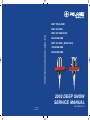
2002 DEEP SNOW SERVICE MANUAL
INDY 500 SKS EURO
600 EDGE RMK
INDY 700 SKS / (EURO SKS)
700 EDGE RMK
800 EDGE RMK
2002 DEEP SNOW
SERVICE MANUAL
PN 9917366
Printed in U.S.A.
PART NUMBER 9917366
DEEP SNOW
SERVICE MANUAL
Foreword
This manual is designed primarily for use by Polaris snowmobile service technicians in a properly equipped
shop. Persons using this manual should have a sound knowledge of mechanical theory, tool use, and shop
procedures in order to perform the work safely and correctly. The technician should read the text and be familiar with service procedures before starting the work. Certain procedures require the use of special tools. Use
only the proper tools, as specified. Cleanliness of parts and tools as well as the work area is of primary importance.
All references to left and right side of the vehicle are from the operator’s perspective when seated in a normal
riding position.
This manual includes procedures for maintenance operations, component identification and unit repair, along
with service specifications for the Polaris Indy (500 Euro) / 700 SKS , Trail RMK, 500 RMK, 600 EDGE RMK,
700 EDGE RMK, 800 EDGE RMK snowmobiles. A table of contents is placed at the beginning of each
chapter, and an alphabetic index is provided at the end of the manual for location of specific page numbers and
service information. Keep this manual available for reference in the shop area.
At the time of publication all information contained in this manual was technically correct. However, all
materials and specifications are subject to change without notice.
Comments or suggestions about this manual may be directed to: Polaris Sales Inc., Service Publications
Department, 2100 Hwy 55 Medina, Minnesota 55340.
Deep Snow Snowmobile Service Manual (PN 9917366)
Copyright 2001 Polaris Sales Inc.
Printed in U.S.A.
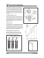
UNDERSTANDING SAFETY LABELS AND INSTRUCTIONS
Throughout these instructions, important information is brought to your attention by the following symbols:
The Safety Alert Symbol means ATTENTION! BECOME ALERT! YOUR SAFETY IS INVOLVED!
DANGER
Failure to follow DANGER instructions will result in severe injury or death to the operator, bystander or person
inspecting or servicing the snowmobile.
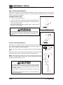
WARNING
Failure to follow WARNING instructions could result in severe injury or death to the operator, bystander or
person inspecting or servicing the snowmobile.
CAUTION:
A CAUTION indicates special precautions that must be taken to avoid personal injury, or snowmobile or property damage.
NOTE:
A NOTE provides key information to clarify instructions.
Trademarks
Polaris acknowledges the following products mentioned in this manual:
FLEXLOC, Registered Trademark of SPS Technologies
Loctite, Registered Trademark of the Loctite Corporation
STA-BIL, Registered Trademark of Gold Eagle
FOX, Registered Trademark of Fox Shox
Nyogel, Trademark of Wm. F. Nye Co.
Fluke, Registered Trademark of John Fluke Mfg. Co.
Mity Vac, Registered Trademark of Neward Enterprises, Inc.
Ammco, Registered Trademark of Ammco Tools, Inc.
Torx, Registered Trademark of Textron
Hilliard, Trademark of the Hilliard Corporation
GENERAL
MAINTENANCE
ENGINE
CARBURETION
DRIVE/DRIVEN CLUTCHES
BODY AND STEERING
SUSPENSIONS
BRAKES AND FINAL DRIVE
ELECTRICAL
WIRING DIAGRAMS
CHAPTER 1
GENERAL INFORMATION
Publication Part Numbers / Service Manuals . . . . . . . . . . . . .
Model Number Identification . . . . . . . . . . . . . . . . . . . . . . . . . . .
Vehicle Identification Number (VIN) . . . . . . . . . . . . . . . . . . . . .
Standard Bolt Torque Specifications . . . . . . . . . . . . . . . . . . . .
Decimal Equivalents . . . . . . . . . . . . . . . . . . . . . . . . . . . . . . . . . .
Tap Drill Size Charts . . . . . . . . . . . . . . . . . . . . . . . . . . . . . . . . . .
Units of Measure Chart . . . . . . . . . . . . . . . . . . . . . . . . . . . . . . .
Recommended Shop Supplies . . . . . . . . . . . . . . . . . . . . . . . . .
Glossary of Terms . . . . . . . . . . . . . . . . . . . . . . . . . . . . . . . . . . . .
General Precautions . . . . . . . . . . . . . . . . . . . . . . . . . . . . . . . . . .
Notes Page . . . . . . . . . . . . . . . . . . . . . . . . . . . . . . . . . . . . . . . . . .
Indy 500 SKS Euro Specifications . . . . . . . . . . . . . . . . . . . . . .
Indy 500 RMK Specifications . . . . . . . . . . . . . . . . . . . . . . . . . .
Indy Trail RMK Specifications . . . . . . . . . . . . . . . . . . . . . . . . . .
600 EDGE RMK Specifications . . . . . . . . . . . . . . . . . . . . . . . . .
Indy 700 SKS (Euro) Specifications . . . . . . . . . . . . . . . . . . . . .
700 EDGE RMK Specifications . . . . . . . . . . . . . . . . . . . . . . . . .
800 EDGE RMK Specifications . . . . . . . . . . . . . . . . . . . . . . . . .
1.1
1.2
1.3
1.4
1.5
1.6
1.7
1.8
1.9 - 1.11
1.12
1.13
1.14 - 1.15
1.16 - 1.17
1.18 - 1.19
1.20 -- 1.21
1.22 -- 1.23
1.24 -- 1.25
1.26 -- 1.27
GENERAL INFORMATION
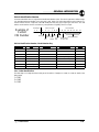
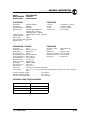
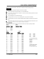
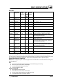
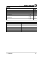
2002 Publication Numbers
Model
Model No.
Owner’s Manual
Supplement
Parts
Manual
Parts
Microfiche
Indy Trail RMK
S02SR5BS
9916935
9916936
9916937
Indy 500 RMK
S02SR5AS
9916932
9916933
9916934
Indy 500 SKS Euro
S02SS5AE
9916941
9916942
9916943
Indy 600 EDGE RMK
Indy 700 SKS (Euro)
9916944
9916938
9916945
9916939
9916946
9916940
700 EDGE RMK - 136²
S02NJ6ES
S02SS7CS
(S02SS5AE)
S02NJ7CSA
9917055
9917056
9917057
700 EDGE RMK - 144²
S02NK7CS
9916953
9916954
9916955
700 EDGE RMK -- 151”
S02NL7CS
9917061
9917062
9917063
800 EDGE RMK - 144²
S02NK8CS
9917058
9917059
9917060
800 EDGE RMK - 151²
S02NL8CS
9916950
9916952
9916953
800 EDGE RMK - 156²
S02NM8CS
9917064
9917065
9917066
2000 Snowmobile Owner’s Manual (All) - PN 9916649
Snowmobile Assembly Manual - PN 9916508
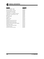
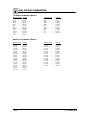
2002 Service Manuals
120 XC SP
Trail Sport
Super Sport, Indy 500, 340 Delux
Two-Up / Touring
Wide Trak LX, 340 Touring, Sport Touring, Trail Touring, 500 Classic Touring, 600 Classic Touring
Trail Luxury
500 Classic, 550 Classic, 600 Classic, 700 Classic
Deep Snow
Trail RMK, 500 RMK, 500 SKS Euro, 700 SKS, Trail RMK, 600/700/800 EDGE RMK
Performance
500 XC, 500/600/700/800 XC SP, 800 XCR
High Performance
440 XCF SP, 440 XC SP, 500/600/700/800 XC SP, 600/700/800 RMK, 800 XCR
Wallcharts
9917361
9917362
9917364
9917363
9917366
9917367
9917365
9917369
1.1
GENERAL INFORMATION
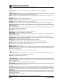
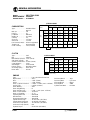
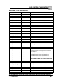
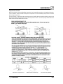
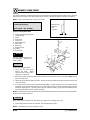
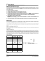
MODEL NUMBER IDENTIFICATION
2002 MODEL DESIGNATION
YEAR DESIGNATION
ENGINE DESIGNATION
S=Snow
S 0 2 S D 5
B S
MODEL / CHASSIS DESIGNATION
S= North American Model
U= European Model
MODEL LINE (4TH DIGIT)
S=Gen II
L= Lite
N= EDGE
W=Mini Indy
MODEL TYPE (5TH DIGIT)
A= Feature Option
B= Basic
C= Feature Option
D= Deluxe
E= Feature Option M--10
F= Feature Option
J= 136 RMK (Edge)
K= 144 RMK (Edge)
L= 151 RMK (Edge)
M= 156 RMK (Edge)
P= Performance
R= RMK (Gen II)
S= SKS
T= Touring
U= Utility
X= Racer
2002
ENGINE DESIGNATION
NUMBERS
1A - 121 F/C OHV 4 cycle Fuji
3A - 340 F/C Piston Port Fuji
4A - 440 F/C Cylinder Reed Fuji
4B - 488 L/C Piston Port Fuji
4C - 440VES L/C Case Reed (domestic)
4D -- 440 F/C Piston Port
4E - 488 F/C Piston Port Fuji
5A - 497 L/C Case Reed 2 Cyl (domestic)
5B - 544 F/C Cylinder Reed
5C - 500 VES L/C Case Reed 2 Cylinder (domestic)
6D - 600/700 L/C Case Reed 2 Cylinder (domestic)
6E - 600/440 VES L/C Case Reed 2 Cylinder (domestic)
7A - 700 L/C Case Reed 2 Cylinder (domestic)
7C -- 700 VES L/C Case Reed 2 Cyl (domestic)
8A - 800 VES L/C Case Reed 3 Cylinder Fuji
8B - 800 L/C Case Reed 2 Cylinder (domestic)
8C -- 800 VES L/C Case Reed 2 Cyl (domestic)
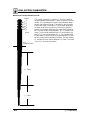
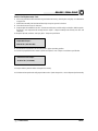
TUNNEL DECAL
MODEL NO.
MADE IN U.S.A.
V.I.N. NO.
THIS VEHICLE CONFORMS TO ALL APPLICABLE
U.S. FEDERAL AND STATE REQUIREMENTS AND
CANADA MOTOR VEHICLE SAFETY STANDARDS
IN EFFECT ON THE DATE OF MANUFACTURE.
MFD. DATE:
PATENT NOTICE
Mfd. by Polaris Industries Inc.. in Roseau, MN under one or
more of the following patents:
Patented Canada
U.S. Patents
882,491/71
3,605,511
3,613,810
5,050,559
883,694/71
3,580,647
3,867,991
5,048,503
864,394/71
3,483,766
4,793,950
5,056,482
Canadian
Rd.
3,533,662
5,038,881
5,099,813
34,573/71
3,545,821
5,172,675
5,074,271
34,572/71
3,605,510
5,090,386
5,191,531
1,227,823/87
3,525,412
5,050,564
3,613,811
7072133
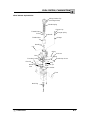
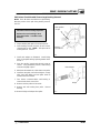
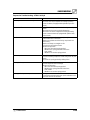
These numbers should be referred to in any correspondence regarding warranty, service or replacement parts.
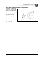
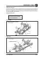
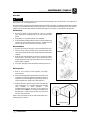
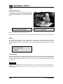
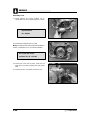
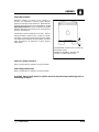
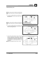
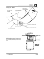
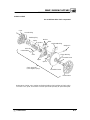
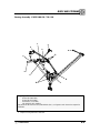
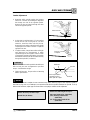
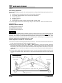
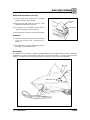
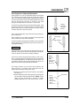
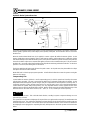
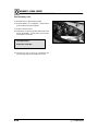
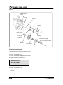
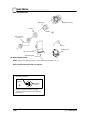
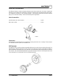
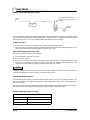
The machine model and serial number identification decal is located on the right front side of the tunnel. The serial number is
permanently stamped into the tunnel. The model number is embossed on the decal.
Whenever corresponding about an engine it is important that the engine model and serial numbers be called out. Laser
engraved model and serial numbers are located on the crankcase (intake side).
1.2
GENERAL INFORMATION
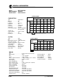
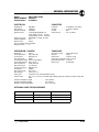
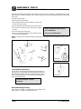
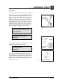
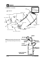
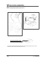
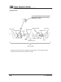
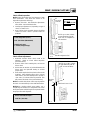
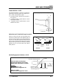
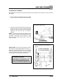
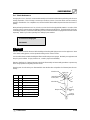
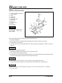
Vehicle Identification Number
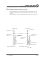
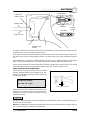
Current snowmobiles have a 17 digit Vehicle Identification Number (VIN). The VIN is organized as follows: Digits
1-3: World Manufacturer Identifier. For Polaris, this is 4XA. Digits 4-9: Vehicle Descriptor Section. Digits 10-17:
Vehicle Indicator Section. Digits 4-8 of the VIN identify the body style, type, engine type, and series. The VIN
and the model number must be used with any correspondence regarding service or repair.
World Mfg. ID
Example of
Current
VIN Number
1
4
2
X
3
A
Vehicle Descriptor
4
S
5
B
6
5
7
B
8
S
Vehicle Identifier
9 10 11 12
0 2 2
0
13 14 15 16 17
0 0
0 0 0
Model
Series
Engine
Year
Individual Serial No.
Size Engine Check
Manufacturing.
Modifier
Digit
Type
Location Code
Body Style
Vehicle Identification Number / Model Number Key
Body Style
Type
Engine Size
Engine Modifier
Series
L=Lite
B=Base Model
1=100-199 cc
A=Fan
S=Domestic
N=Edge
D=Deluxe
2=200-299 cc
B=Liquid Twin
U=Europe
S=Gen II
P=Performance
3=300-399 cc
C=Case Reed Twin
W=Mini
R=RMK
4=400-499 cc
D=Liquid Triple
S=SKS
5=500-599 cc
E=Case Reed Triple
T=Touring
6=600-699 cc
U=Utility
7=700-799 cc
X=Racer
8=800-899 cc
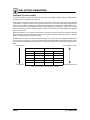
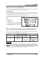
Year / Letter Identification
The tenth digit of a 17 digit VIN is the model year of the vehicle. Example: W = 1998; X = 1999 etc. Refer to the
listing below.
1 = 2001
2 = 2002
3 = 2003
1.3
GENERAL INFORMATION
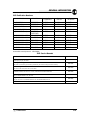
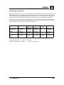
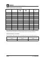
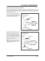
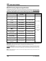
Standard Torque Specifications
The following torque specifications are to be used as a general guideline when torque value is not specified. There
are exceptions in the steering, suspension, and engine areas. Always consult the torque chart and the specific
manual section for torque values of fasteners.
Bolt Size
Threads/In
(MM/Thread)
Grade 2
Torque in. lbs. (Nm)
24 . . . . . . . . . . . . . . 27 (3.1) . . . . . . . . . . . . . . . .
32 . . . . . . . . . . . . . . 31 (3.6) . . . . . . . . . . . . . . . .
Torque ft. lbs. (Nm)*
1/4
20 . . . . . . . . . . . . . . 5 (7) . . . . . . . . . . . . . . . . . .
1/4
28 . . . . . . . . . . . . . . 6 (8) . . . . . . . . . . . . . . . . . .
5/16 18 . . . . . . . . . . . . . . 11 (15) . . . . . . . . . . . . . . . .
5/16 24 . . . . . . . . . . . . . . 12 (16) . . . . . . . . . . . . . . . .
3/8
16 . . . . . . . . . . . . . . 20 (27) . . . . . . . . . . . . . . . .
3/8
24 . . . . . . . . . . . . . . 23 (32) . . . . . . . . . . . . . . . .
7/16 14 . . . . . . . . . . . . . . 30 (40) . . . . . . . . . . . . . . . .
7/16 20 . . . . . . . . . . . . . . 35 (48) . . . . . . . . . . . . . . . .
1/2
13 . . . . . . . . . . . . . . 50 (69) . . . . . . . . . . . . . . . .
1/2
20 . . . . . . . . . . . . . . 55 (76) . . . . . . . . . . . . . . . .
*To convert ft. lbs. to Nm multiply foot pounds by 1.356.
*To convert Nm to ft. lbs. multply Nm by .7376.
#10
#10
1.4
-
Grade 5
Grade 8
43 (5) . . . . . . . . . . . . . . . 60 (6.9)
49 (5.6) . . . . . . . . . . . . . . 68 (7.8)
8 (11) . . . . . . . . . . . . . . . .
10 (14) . . . . . . . . . . . . . .
17 (23) . . . . . . . . . . . . . .
19 (26) . . . . . . . . . . . . . .
30 (40) . . . . . . . . . . . . . .
35 (48) . . . . . . . . . . . . . .
50 (69) . . . . . . . . . . . . . .
55 (76) . . . . . . . . . . . . . .
75 (104) . . . . . . . . . . . . .
90 (124) . . . . . . . . . . . . .
12 (16)
14 (19)
25 (35)
29 (40)
45 (62)
50 (69)
70 (97)
80 (110)
110 (152)
120 (166)
GENERAL INFORMATION
1/64 . . . . . . . . . . . . . . . . . . . . . . . . .
1/32 . . . . . . . . . . . . . . . . . . .
3/64 . . . . . . . . . . . . . . . . . . . . . . . . .
1/16 . . . . . . . . . . . . . .
5/64 . . . . . . . . . . . . . . . . . . . . . . . . .
3/32 . . . . . . . . . . . . . . . . . . .
7/64 . . . . . . . . . . . . . . . . . . . . . . .
1/8 . . . . . . . . .
9/64 . . . . . . . . . . . . . . . . . . . . . . . . .
5/32 . . . . . . . . . . . . . . . . . . .
11/64 . . . . . . . . . . . . . . . . . . . . . . . .
3/16 . . . . . . . . . . . . . .
13/64 . . . . . . . . . . . . . . . . . . . . . . . .
7/32 . . . . . . . . . . . . . . . . . . .
15/64 . . . . . . . . . . . . . . . . . . . . . . . .
1/4 . . . . . . . . . .
17/64 . . . . . . . . . . . . . . . . . . . . . . . .
9/32 . . . . . . . . . . . . . . . . . . .
19/64 . . . . . . . . . . . . . . . . . . . . . . . .
5/16 . . . . . . . . . . . . . .
21/64 . . . . . . . . . . . . . . . . . . . . . . . .
11/32 . . . . . . . . . . . . . . . . . .
23/64 . . . . . . . . . . . . . . . . . . . . . . . .
3/8 . . . . . . . . . .
25/64 . . . . . . . . . . . . . . . . . . . . . . . .
13/32 . . . . . . . . . . . . . . . . . .
27/64 . . . . . . . . . . . . . . . . . . . . . . . .
7/16 . . . . . . . . . . . . . .
29/64 . . . . . . . . . . . . . . . . . . . . . . . .
15/32 . . . . . . . . . . . . . . . . . .
31/64 . . . . . . . . . . . . . . . . . . . . . . . .
1/2 . . . . . . . . . .
33/64 . . . . . . . . . . . . . . . . . . . . . . . .
17/32 . . . . . . . . . . . . . . . . . .
35/64 . . . . . . . . . . . . . . . . . . . . . . . .
9/16 . . . . . . . . . . . . . .
37/64 . . . . . . . . . . . . . . . . . . . . . . . .
19/32 . . . . . . . . . . . . . . . . . .
39/64 . . . . . . . . . . . . . . . . . . . . . . . .
5/8 . . . . . . . . . .
41/64 . . . . . . . . . . . . . . . . . . . . . . . .
21/32 . . . . . . . . . . . . . . . . . .
43/64 . . . . . . . . . . . . . . . . . . . . . . .
11/16 . . . . . . . . . . . . .
45/64 . . . . . . . . . . . . . . . . . . . . . . . .
23/32 . . . . . . . . . . . . . . . . . .
47/64 . . . . . . . . . . . . . . . . . . . . . . . .
3/4 . . . . . . . . . .
49/64 . . . . . . . . . . . . . . . . . . . . . . . .
25/32 . . . . . . . . . . . . . . . . . .
51/64 . . . . . . . . . . . . . . . . . . . . . . . .
13/16 . . . . . . . . . . . . .
53/64 . . . . . . . . . . . . . . . . . . . . . . . .
27/32 . . . . . . . . . . . . . . . . . .
55/64 . . . . . . . . . . . . . . . . . . . . . . . .
7/8 . . . . . . . . . .
57/64 . . . . . . . . . . . . . . . . . . . . . . . .
29/32 . . . . . . . . . . . . . . . . . .
59/64 . . . . . . . . . . . . . . . . . . . . . . .
15/16 . . . . . . . . . . . . .
61/64 . . . . . . . . . . . . . . . . . . . . . . . .
31/32 . . . . . . . . . . . . . . . . . .
63/64 . . . . . . . . . . . . . . . . . . . . . . . .
.0156
.0312 . . . . . . . . . . . . . . . .
.0469
.0625
.0781 . . . . . . . . . . . . . . . .
.0938
.1094 . . . . . . . . . . . . . . . .
.1250
.1406
.1563 . . . . . . . . . . . . . . . .
.1719
.1875 . . . . . . . . . . . . . . . .
.2031
.2188
.2344 . . . . . . . . . . . . . . . .
.25
.2656 . . . . . . . . . . . . . . . .
.2813
.2969
.3125 . . . . . . . . . . . . . . . .
.3281
.3438 . . . . . . . . . . . . . . . .
.3594
.375
.3906 . . . . . . . . . . . . . . . .
.4063
.4219 . . . . . . . . . . . . . . . .
.4375
.4531
.4688 . . . . . . . . . . . . . . . .
.4844
.5 . . . . . . . . . . . . . . . . . . .
.5156
.5313
.5469 . . . . . . . . . . . . . . . .
.5625
.5781 . . . . . . . . . . . . . . . .
.5938
.6094
.625 . . . . . . . . . . . . . . . . .
.6406
.6563 . . . . . . . . . . . . . . . .
.6719
.6875
.7031 . . . . . . . . . . . . . . . .
.7188
.7344 . . . . . . . . . . . . . . . .
.75
.7656
.7813 . . . . . . . . . . . . . . . .
.7969
.8125 . . . . . . . . . . . . . . . .
.8281
.8438
.8594 . . . . . . . . . . . . . . . .
.875
.8906 . . . . . . . . . . . . . . . .
.9063
.9219
.9375 . . . . . . . . . . . . . . . .
.9531
.9688 . . . . . . . . . . . . . . . .
.9844
1 mm = .0394²
2 mm = .0787²
3 mm = .1181²
4 mm = .1575²
5 mm = .1969²
6 mm = .2362²
7 mm = .2756²
8 mm = .3150²
9 mm = .3543²
10 mm = .3937²
11 mm = .4331²
12 mm = .4724²
13 mm = .5118
14 mm = .5512²
15 mm = .5906²
16 mm = .6299²
17 mm = .6693²
18 mm = .7087²
19 mm = .7480²
20 mm = .7874²
21 mm = .8268²
22 mm = .8661²
23 mm = .9055²
24 mm = .9449²
25 mm = .9843
1.5
GENERAL INFORMATION
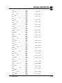
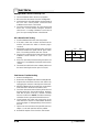
SAE Tap Drill Sizes
Thread Size
Drill Size
Thread Size
Drill Size
#0-80
#1-64
#1-72
#2-56
#2-64
#3-48
#3-56
#4-40
#4-48
#5-40
#5-44
#6-32
#6-40
#8-32
#8-36
#10-24
#10-32
#12-24
#12-28
1/4-20
1/4-28
5/16-18
5/16-24
3/8-16
3/8-24
7/16-14
7/16-20
3/64
53
53
51
50
5/64
45
43
42
38
37
36
33
29
29
24
21
17
4.6mm
7
3
F
I
O
Q
U
25/64
1/2-13
1/2-20
9/16-12
9/16-18
5/8-11
5/8-18
3/4-10
3/4-16
7/8-9
7/8-14
1-8
1-12
1 1/8-7
1 1/8-12
1 1/4-7
1 1/4-12
1 1/2-6
1 1/2-12
1 3/4-5
1 3/4-12
2-4 1/2
2-12
2 1/4-4 1/2
2 1/2-4
2 3/4-4
3-4
27/64
29/64
31/64
33/64
17/32
37/64
21/32
11/16
49/64
13/16
7/8
59/64
63/64
1 3/64
1 7/64
1 11/64
1 11/32
1 27/64
1 9/16
1 43/64
1 25/32
1 59/64
2 1/32
2 1/4
2 1/2
2 3/4
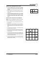
Metric Tap Drill Sizes
Tap Size
3 x .50
3 x .60
4 x .70
4 x .75
5 x .80
5 x .90
6 x 1.00
7 x 1.00
8 x 1.00
8 x 1.25
9 x 1.00
9 x 1.25
10 x 1.25
10 x 1.50
11 x 1.50
12 x 1.50
12 x 1.75
1.6
Drill Size
#39
3/32
#30
1/8
#19
#20
#9
16/64
J
17/64
5/16
5/16
11/32
R
3/8
13/32
13/32
Decimal Equivalent
0.0995
0.0937
0.1285
0.125
0.166
0.161
0.196
0.234
0.277
0.265
0.3125
0.3125
0.3437
0.339
0.375
0.406
0.406
Nearest Fraction
3/32
3/32
1/8
1/8
11/64
5/32
13/64
15/64
9/32
17/64
5/16
5/16
11/32
11/32
3/8
13/32
13/32
GENERAL INFORMATION
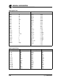
Unit of Measure
Multiplied by
Converts to
ft. lbs.
x 12
= in. lbs.
in. lbs.
x .0833
= ft. lbs.
ft. lbs.
x 1.356
= Nm
in. lbs.
x .0115
= kg-m
Nm
x .7376
= ft. lbs.
kg-m
x 7.233
= ft. lbs.
kg-m
x 86.796
= in. lbs.
kg-m
x 10
= Nm
in.
x 25.4
=mm
mm
x .03937
= in.
in.
x 2.54
= cm
mile (mi.)
x 1.6
= km
km
x .6214
= mile (mi.)
Ounces (oz)
x 28.35
= Grams (g)
Grams (g)
x 0.035
= Ounces (oz)
cc
x .03381
= Fluid Ounces (oz)
lb.
x .454
= kg
kg
x 2.2046
= lb.
Cubic inches (cu in)
x 16.387
= Cubic centimeters (cc)
Cubic centimeters (cc)
x 0.061
= Cubic inches (cu in)
Imperial pints (Imp pt)
x 0.568
= Liters (l)
Liters (l)
x 1.76
= Imperial pints (Imp pt)
Imperial quarts (Imp qt)
x 1.137
= Liters (l)
Liters (l)
x 0.88
= Imperial quarts (Imp qt)
Imperial quarts (Imp qt)
x 1.201
= US quarts (US qt)
US quarts (US qt)
x 0.833
= Imperial quarts (Imp qt)
US quarts (US qt)
x 0.946
= Liters (l)
Liters (l)
x 1.057
= US quarts (US qt)
US gallons (US gal)
x 3.785
=Liters (l)
Liters (l)
x 0.264
= US gallons (US gal)
Pounds - force per square inch (psi)
x 6.895
= Kilopascals (kPa)
Kilopascals (kPa)
x 0.145
= Pounds - force per square inch (psi)
Kilopascals (kPa)
x 0.01
= Kilograms - force per square cm
Kilograms - force per square cm
x 98.1
= Kilopascals (kPa)
°C to °F: 9 (°C + 40) ¸ 5 -- 40 = °F
°F to °C: 5 (°F + 40) ¸ 9 -- 40 = °C
1.7
GENERAL INFORMATION
Description
Chaincase Lubricant - Quart . . . . . . . . . . . . . . . . . . . . . . .
Chaincase Lubricant - Gallon . . . . . . . . . . . . . . . . . . . . . .
Chaincase Lubricant - 2.5 Gallon . . . . . . . . . . . . . . . . . . .
Fuel System Deicer (Isopropyl) . . . . . . . . . . . . . . . . . . . . .
Loctite Primer T - 6 Oz. Aerosol . . . . . . . . . . . . . . . . . . . .
Loctite RC 680 - 10cc Retaining Compound . . . . . . . . . .
Loctite/Chisel -- Gasket Remover - 18 Oz. . . . . . . . . . . .
Metal Polish - 8 Oz. . . . . . . . . . . . . . . . . . . . . . . . . . . . . . . .
DOT 3 Brake Fluid . . . . . . . . . . . . . . . . . . . . . . . . . . . . . . .
Fogging Oil . . . . . . . . . . . . . . . . . . . . . . . . . . . . . . . . . . . . . .
Nyogelt Grease . . . . . . . . . . . . . . . . . . . . . . . . . . . . . . . . .
Fox Shock Oil . . . . . . . . . . . . . . . . . . . . . . . . . . . . . . . . . . . .
Premium All Season Grease (14 oz) . . . . . . . . . . . . . . . .
Premium All Season Grease (3 oz) . . . . . . . . . . . . . . . . .
Premium 60/40 Anti-Freeze/Coolant . . . . . . . . . . . . . . . .
Premium Carbon Clean Fuel System Additive . . . . . . . .
Polaris Battery Tender . . . . . . . . . . . . . . . . . . . . . . . . . . . .
Carbon Clean Fuel System Additive . . . . . . . . . . . . . . . . .
T-9 Metal Protectant . . . . . . . . . . . . . . . . . . . . . . . . . . . . . .
Crankcase Sealant 3 Bond 1215 . . . . . . . . . . . . . . . . . . .
1.8
Part Number
2871280
2870464
2872281
2870505
2870585
2870584
2870601
2870632
2870990
2870791
2871329
2870995
2871423
2871322
2871323
2871326
2871076
2871326
2871064
2871557
GENERAL INFORMATION
ACS: Alternator control switch.
ACV: Alternating current voltage.
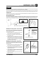
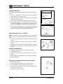
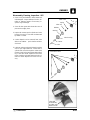
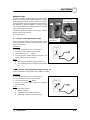
Air Gap Spark Test: A good check for ignition voltage and general ignition system condition. Spark should arc 3/8” (1
cm) minimum from end of high tension lead to ground. Several testers are available commercially.
Alternator: Electrical generator producing alternating current voltage.
Bore: Diameter of cylinder.
BTDC: Before Top Dead Center.
Bump Steer: When skis toe in and toe out through suspension travel.
CDI: Capacitor Discharge Ignition. Ignition system which stores voltage generated by the stator plate exciter coil in a
capacitor or condenser (in CDI box). At the proper moment a voltage generated by the stator plate pulser coil closes an
electronic switch (thyristor) in the CDI box and allows the voltage in the capacitor to discharge into the primary windings
of the ignition coil.
Center Cylinder: On three cylinder engines, the cylinder between Mag and PTO ends.
Center Distance: Distance between center of crankshaft and center of driven clutch shaft.
Chain Pitch: Distance between chain link pins (No. 35 = 3/8” or 1 cm). Polaris measures chain length in number of
pitches.
Clutch Buttons: Plastic bushings which transmit rotation of the clutch to the movable sheave in the drive and driven
clutch.
Clutch Offset: Drive and driven clutches are offset so that drive belt will stay nearly straight as it moves along the clutch
face as the engine torques back.
Clutch Weights: Three levers in the drive clutch which relative to their weight, profile and engine RPM cause the drive
clutch to close.
Coil: A winding of wire around an iron core which has the ability to generate an electrical current when a magnetic field
passes through it.
Combustion Chamber: Space between cylinder head and piston dome at TDC.
Compression: Reduction in volume or squeezing of a gas.
Condenser/Capacitor: A storage reservoir for electricity, used in both E.T. and CDI systems.
Crankshaft Run-Out: Run-out or “bend” of crankshaft measured with a dial indicator while crankshaft is supported
between centers on V blocks or resting in lower half of crankcase. Measure at various points especially at PTO.
Maximum allowable run-out is .006” (.02 cm).
DCV: Direct current voltage.
Detonation: The spontaneous ignition of the unburned fuel/air mixture after normal spark ignition. Piston looks
“hammered” through, rough appearance around hole. Possible causes: 1) lean fuel/air mixture; 2) low octane fuel; 3)
over-advanced ignition timing; 4)compression ratio too high for the fuel octane.
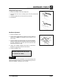
Dial Bore Gauge: A cylinder measuring instrument which uses a dial indicator. Good for showing taper and
out-of-round in the cylinder bore.
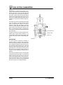
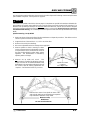
Displacement: The volume of the cylinder displaced by
Bore2 x Stroke x 3.1416
the piston as it travels from BDC to TDC. The formula is:
= Displacement in
4
CCs
Effective Compression Ratio: Compression ratio measured from after the piston closes the exhaust port.
Electrical Open: Open circuit. An electrical circuit which isn’t complete. (i.e. poor connections or broken wire at hi-lo
beam switch resulting in loss of headlights.
Electrical Short: Short circuit. An electrical circuit which is completed before the current reaches the intended
component. (i.e. a bare wire touching the snowmobile chassis under the seat resulting in loss of taillights and brake
lights).
End Seals: Rubber seals at each end of the crankshaft.
Engagement RPM: Engine RPM at which the drive clutch engages to make contact with the drive belt.
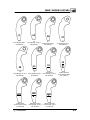
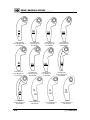
Flat Head Bolt: To be used where finished surfaces require a flush fastening unit. Countersunk.
Foot Pound: Ft. lb. A force of one pound at the end of a lever one foot in length, applied in a rotational direction.
g: Gram. Unit of weight in the metric system.
Head Volume: Cylinder head capacity in cc, head removed from engine with spark plug installed.
1.9
GENERAL INFORMATION
Heat Exchanger: A device used to transfer heat. They dissipate engine heat to the atmosphere.
Hex Head Bolt: Standard type of wrench-applied hexagon head, characterized by clean, sharp corners trimmed
to close tolerances. Recommended for general commercial applications.
Hi-Fax: Trademark of Himont Advanced Materials. The special slide material which fits onto the bottom of the
suspension rails.
High Side: Sled pushes or tips up toward outside of turn.
High Tension Wire: The heavy insulated wire which carries the high secondary voltage from the coil to the spark plug.
Hole Shot: A term used when machine starts a race from a dead stop.
Holed Piston: Piston in which a hole has formed on the dome. Possible causes: 1) detonation; 2) pre-ignition.
Ignition Coil: A type of transformer which increases voltage in the primary windings (approx. 200V) to a higher voltage
in the secondary windings (approx. 14KV - 32KV) through inductions. Secondary voltage is high enough to arc the air
gap at the spark plug.
Ignition Generating Coil: Exciter coil or primary charge coil. Stator plate coil which generates primary ignition voltage.
CDI system uses one ignition generating coil.
Inch Pound: In. lb. 12 in. lbs. = 1 ft. lb.
Kg/cm2: Kilograms per square centimeter. Metric equivalent of PSI.
Keystone Ring: A piston ring with bevel on upper surface.
Kilogram/meter: A force of one kilogram at the end of a lever one meter in length, applied in a rotational direction.
Metric equivalent of ft. lbs.
L Ring: A wide face piston ring with an ”L” shaped cross section. Leg of ”L” goes up when installing on piston.
Labyrinth Seal: A pressure type center seal identified by series of grooves and lands. Polaris engines us this type of
seal to separate the cylinders in the crankcase halves.
Left Side: Always referred to based on normal operating position of the driver.
Lighting Coil: Generates voltage for lights, battery charging, etc by electromagnetic induction.
Loose: When the rear of the vehicle slides outward in a turn. The track does not grab sufficiently.
mm: Millimeter. Unit of length in the metric system. 1mm = .040”.
Mag End: Flywheel side of engine.
Magnetic Induction: As a conductor (coil) is moved through a magnetic field, a voltage will be generated in the
windings. This is how mechanical energy in our engines is converted to electrical energy in the lighting coil, ignition
generating coils and trigger coil.
Ohm: The measurement of electrical resistance opposing current flow.
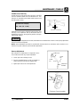
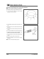
Oval Head Screw: Fully specified as ”oval countersunk”, this head is identical to the standard flat head, but
possesses a rounded upper surface for attractiveness of design.
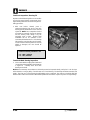
PTO End: Power Take Off drive (clutch side).
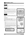
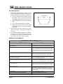
Pan Head Screw: Provides a low, large diameter head, but with characteristically high outer edges along the
outer edge of the head where driving action is most effective. Slightly different head contour when supplied with Phillips
Recess. See dotted line.
Piston Clearance: Total distance between piston and cylinder wall.
Piston Erosion: Piston dome melts. Usually occurs at the exhaust port area. Possible causes: 1) lean fuel/air mixture;
2) improper spark plug heat range; 3) Poor fuel.
Pre-Ignition: A problem in combustion where the fuel/air mixture is ignited before normal spark ignition. Piston looks
melted at area of damage. Possible causes: 1)incorrect spark plug heat range; 2) spark plug not properly torqued; 3)
“glowing” piece of head gasket, metal burr or carbon in the combustion chamber; 4) lean fuel/air mixture; 5) Incorrect
ignition timing.
Primary Circuit: This circuit is responsible for the voltage build up in the primary windings of the coil. In the CDI system
the parts include the exciter coil, the trigger coil, the wires from stator plate to CDI box and to the low resistance primary
windings in the ignition coil.
Primary Clutch: Drive clutch on engine.
Primary Compression: Pressure built up in the crankcase of a two stroke engine.
1.10
GENERAL INFORMATION
psi.: Pounds per square inch.
Pushing: When the front of the vehicle does not steer as much as the driver desires. The skis do not grab sufficiently.
R & R: Remove and replace.
RFI: Radio Frequency Interference. Caused by high voltage from the ignition system. There are special plug caps and
spark plugs to help eliminate this problem. Mandated in Canada.
RPM: Revolutions Per Minute.
Resistance: In the mechanical sense, friction or load. In the electrical sense, ohms. Both result in energy conversion to
heat.
Right Side: Always referred to based on normal operating position of the driver.
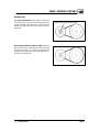
Round Head Screw:The familiar head most universally used for general application. Good slot depth, ample
underhead bearing surface and finished appearance are characteristic of this head.
Running Time: Ignition timing at specified RPM.
Secondary Circuit: This circuit consists of the large secondary coil windings, high tension wire and ground through the
spark plug air gap.
Secondary Clutch: Driven clutch on chaincase or jackshaft.
Seized Piston: Galling of the sides of a piston. Usually there is a transfer of aluminum from the piston onto the cylinder
wall. Possible causes: 1) improper lubrication; 2) excessive temperatures; 3) insufficient piston clearance; 4) stuck
piston rings.
Self Steer: Pulling the machine to the inside of the track.
Spark Plug Reach: Length of threaded portion of spark plug. Polaris uses 3/4” (2 cm) reach plugs.
Static Timing: Ignition timing when engine is at zero RPM.
Stator Plate: The plate mounted under the flywheel supporting the primary ignition components and lighting coils.
Stroke: The maximum movement of the piston from bottom dead center to top dead center. It is characterized by 180°
of crankshaft rotation.
Surge Tank: The fill tank in the liquid cooling system.
TDC: Top Dead Center. Piston’s most outward travel from crankshaft.
Transfer: The movement of fuel/air from the crankcase to the combustion chamber in a two stroke engine.
Trigger Coil: Pulser coil. Generates the voltage for triggering (closing) the thyristor and timing the spark in CDI
systems. Small coil mounted at the top of the stator plate next to the ignition generating coil, or on the outside of the
flywheel.
V Regulator: Voltage regulator. Maintains maximum lighting coil output at approx. 14.5 ACV as engine RPM
increases.
Venturi: An area of air constriction. A venturi is used in carburetors to speed up air flow which lowers pressure in venturi
to below atmospheric pressure, causing fuel to be pushed through jets, etc., and into the venturi to be mixed with air and
form a combustible air/fuel mixture.
Volt: The unit of measure for electrical pressure of electromotive force. Measured by a voltmeter in parallel with the
circuit.
Watt: Unit of electrical power. Watts = amperes x volts.
1.11
GENERAL INFORMATION
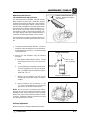
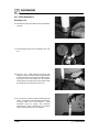
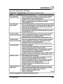
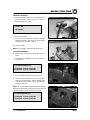
In order to perform service work efficiently and to prevent costly errors, the technician should read the text in this
manual, thoroughly familiarizing him/herself with procedures before beginning. Photographs and illustrations
have been included with the text as an aid. Notes, cautions and warnings have also been included for clarification
of text and safety concerns. However, a knowledge of mechanical theory, tool use and shop procedures is
necessary to perform the service work safely and satisfactorily. Use only genuine Polaris service parts.
Cleanliness of parts and tools as well as the work area is of primary importance. Dirt and foreign matter will act
as an abrasive and cause damage to precision parts. Clean the snowmobile before beginning service. Clean new
parts before installing.
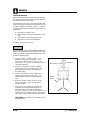
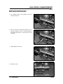
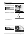
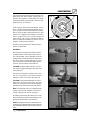
Watch for sharp edges which can cause personal injury, particularly in the area of the tunnel. Protect hands
with gloves when working with sharp components.
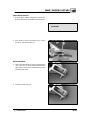
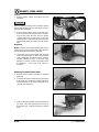
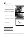
If difficulty is encountered in removing or installing a component, look to see if a cause for the difficulty can be
found. If it is necessary to tap the part into place, use a soft face hammer and tap lightly.
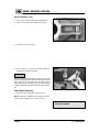
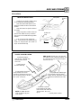
Some of the fasteners in the snowmobile were installed with locking agents. Use of impact drivers or
wrenches will help avoid damage to fasteners.
Always follow torque specifications as outlined throughout this manual. Incorrect torquing may lead to serious
machine damage or, as in the case of steering components, can result in injury or death for the rider(s).
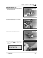
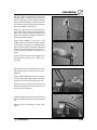
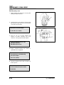
If a torquing sequence is indicated for nuts, bolts or screws, start all fasteners in their holes and hand tighten.
Then, following the method and sequence indicated in this manual, tighten evenly to the specified torque value.
When removing nuts, bolts or screws from a part with several fasteners, loosen them all about 1/4 turn before
removing them.
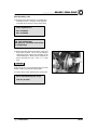
If the condition of any gasket or O-Ring is in question, replace it with a new one. Be sure the mating surfaces
around the gasket are clean and smooth in order to avoid leaks.
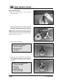
Some procedures will require removal of retaining rings or clips. Because removal weakens and deforms
these parts, they should always be replaced with new parts. When installing new retaining rings and clips use care
not to expand or compress them beyond what is required for installation.
Because removal damages seals, replace any oil or grease seals removed with new parts.
Polaris recommends the use of Polaris lubricants and greases, which have been specially formulated for the
top performance and best protection of our machines. In some applications, such as the engine, warranty
coverage may become void if other brands are substituted.
Grease should be cleaned from parts and fresh grease applied before reassembly of components.
Deteriorating grease loses lubricity and may contain abrasive foreign matter.
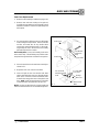
Whenever removing or reinstalling batteries, care should be taken to avoid the possibility of explosion
resulting in serious burns. Always disconnect the negative (black) cable first and reconnect it last. Battery
electrolyte contains sulphuric acid and is poisonous! Serious burns can result from contact with the skin, eyes or
clothing. ANTIDOTE: External - Flush with water. Internal - Drink large quantities or water or milk. Follow with
milk of magnesia, beaten egg, or vegetable oil. Call physician immediately. Eyes - Flush with water for 15 minutes
and get prompt medical attention.
1.12
GENERAL INFORMATION
Notes
1.13
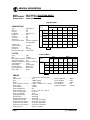
GENERAL INFORMATION
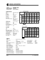
MODEL: . . . . . . . . . . INDY 500 SKS EUROPEAN
MODEL NUMBER: . E02SS5AE
ENGINE MODEL: . . S2209--5044PL5A
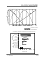
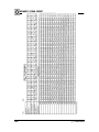
JETTING CHART
AMBIENT TEMPERATURE
CARBURETION
Type . . . . . . . . . . . . . . . .
Main Jet . . . . . . . . . . . .
Pilot Jet . . . . . . . . . . . . .
Jet Needle . . . . . . . . . . .
Needle Jet . . . . . . . . . . .
Cutaway . . . . . . . . . . . .
Fuel Mixture Screw . . .
Valve Seat . . . . . . . . . . .
Fuel Octane (R+M/2) .
TM 38 Mikuni
370
45
9FH4--57/3
P-6
1.5
2 Turns
1.5
87 Non-Oxygenated
89 Oxygenated
Throttle Gap
Under Cutaway . . . . . . 0.098² (2.5mm)
Starter Jet . . . . . . . . . . . 155
Pilot Air Jet . . . . . . . . . . 1.0
Below -30°F
Below -34°C
34 C
-30_ to --10_F
-34_to
-23_C
-34
to -23
C
--10_to +10_F
-12_C
--23_
23 to --12
C
+10_to +30_F
-12_to
-1_C
-12
to --1
C
+30_to +50_F
+10_C
--1_to
1 to +10
C
Above +50_F
+10_C
Above +10
C
0--600
(0--2000)
390
#3
380
#3
360
#3
350
#3
330
#3
320
#3
600--1200
(2000--4000)
370
#3
360
#3
340
#3
330
#3
310
#3
300
#2
1200--1800
1200
1800
( 000 -6000)
6000)
(4000-
350
#3
330
#3
320
#3
300
#3
290
#2
280
#2
1800--2400
(6000 -8000)
8000)
(6000-
330
#3
310
3
0
#3
300
#3
290
90
#2
370
3
0
#2
250
50
#2
2400--3000
(8000 -10000)
10000)
(8000-
300
#3
290
90
#3
280
80
#2
260
60
#2
250
50
#2
230
30
#1
3000--3700
(10000 -12000)
12000)
(10000-
280
80
#3
270
0
#2
250
50
#2
240
0
#2
220
0
#2
210
0
#2
Altitude
Meters
((Feet))
XXX
#X
- # refers to the clip position from top of jet needle.
CLUTCH
Type . . . . . . . . . . . . . . . .
Belt . . . . . . . . . . . . . . . . .
Belt Width (Projected) .
Side Angle (Overall) . .
Outside Circumference
Center Distance . . . . . .
Shift Weights . . . . . . . .
Primary Spring . . . . . . .
Secondary Spring . . . .
Driven Helix . . . . . . . . .
P 85
3211074
1.438²
28°
47.625²
12.00²
10-56 Bushed
Dark Blue / White
Silver
R32 #2
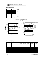
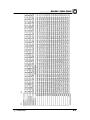
CLUTCH CHART
DRIVE
Altitude
Meters
(Feet)
DRIVEN
Shift
Weight
Clutch
Spring
Clutch
Spring
Driven
Helix
Chaincase
Gearing
0-900
(0-3000)
10-56
Bushed
Dark Blue /
White
Silver
R32
#2
18-41-68P
HYVO
900-1800
(3000-6000)
10-AL
Bushed
Almond /
Round
Silver
R32
#2
18-41-68P
HYVO
1800-2700
(6000-9000)
10
Bushed
Almond /
Round
Silver
R32
#2
18-41-68P
HYVO
2700-3700
(9000-12000)
10M5
Bushed
Almond /
Round
Silver
R32
#2
18-41-68P
HYVO
- Production Setting
ENGINE
Type . . . . . . . . . . . . . . . . . . . . . . .
Displacement . . . . . . . . . . . . . . .
Bore . . . . . . . . . . . . . . . . . . . . . . .
Stroke . . . . . . . . . . . . . . . . . . . . .
Piston / Cylinder Clearance . . .
Service Limit . . . . . . . . . . . . . . . .
Piston Marking . . . . . . . . . . . . . .
Piston Ring Marking . . . . . . . . .
Piston Ring End Gap . . . . . . . .
Head ccs (Uninstalled) . . . . . . .
Head ccs (Installed) . . . . . . . . .
Operating RPM±200 . . . . . . . . .
Idle RPM±200 . . . . . . . . . . . . . .
Engagement RPM±300 . . . . . .
Cylinder Head Torque . . . . . . . .
Cylinder Base Nut Torque . . . .
Crankcase Torque (8mm) . . . . .
Crankcase Torque (10mm) . . .
Flywheel Torque . . . . . . . . . . . . .
1.14
Liquid Cooled Case Reed Twin
500cc
2.776²² (70.5mm)
2.520²² (64mm)
0.0045² - 0.0063² (0.11 - 0.16mm)
N/A
3021038
N/A
0.012² - 0.018² (.30 - .46mm)
27.5±.50cc
25cc
8000 RPM
1500 RPM
4200 RPM
20-24 ft.lbs. (28-33Nm)
30-34 ft.lbs. (41-47 Nm)
20-24 ft.lbs. (28-33 Nm)
N/A
90 ft.lbs. (124 Nm)
Fuel Pump Manuf. . . . . .
Fuel Pump Mark . . . . . . .
Oil Pump Manuf. . . . . . . .
Oil Pump Mark . . . . . . . .
Cylinder Head Mark . . . .
N/A
N/A
Mikuni
2540051
3021048
GENERAL INFORMATION
MODEL: . . . . . . . . . . INDY 500 SKS EUROPEAN
MODEL NUMBER: . E02SS5AE
ENGINE MODEL: . . S2209--5044PL5A
ELECTRICAL
CAPACITIES
Flywheel I.D. . . . . . .
CDI Marking . . . . . . .
Alternator Output . . .
Ignition Timing . . . . .
4010523
4010584
280 Watts
12° BTDC@22500 RPM
0.0327² BTDC
0.8294mm BTDC
Spark Plug / Gap . . . Champion RN2C / 0.028² (0.7mm)
Voltage Regulator . . LR7
Electric Start . . . . . . . Option
LR7= Full wave voltage regulator
Magneto Pulses . . . . 6
Fuel Tank . . . . . . . . . .
Oil Tank . . . . . . . . . . . .
Coolant . . . . . . . . . . . .
Chaincase Oil . . . . . . .
SUSPENSION / CHASSIS
CHAINCASE
11.8 gallons (44.7 liters)
3 quarts (2.8 liters)
5 quarts (4.7 liters)
11 fl. oz. (325cc)
Body Style . . . . . . . .
Front Suspension . .
Front Shocks . . . . . .
IFS Spring Rate . . . .
Front Spring Preload
Front Vertical Travel
Rear Suspension . . .
Rear Axle Travel . . .
Front Track Shock . .
Spring Rate . . . . . . . .
Rear Track Shock . .
Rear Springs . . . . . .
Track Type . . . . . . . .
Track Tension . . . . . .
Gen II
Sprockets / Chain . . . 18-41, 68P HYVO
Indy XC 10
Reverse . . . . . . . . . . . . Option
Indy Select
Brake Pads . . . . . . . . . Type 81, Large
100#/in.
Chaincase Center Dist.7.05² (17.91cm)
3/4² Thread Adjust
Driveshaft Sprockets . 2 Drivers Wide
9.6² (24.4cm)
Brake Type . . . . . . . . . Polaris HPB
XTRA-10 EURO
9.5² (24.1cc)
Nitrogen Cell
190#/in. variable
Indy Select
.405² (sq.) / 77°
15²x136²x1.25² (38.1x345.44x3.175cm)
3/8² - 1/2² (1-1.3 cm) slack with 10# (4.54kg) weight 16² (40.64cm) ahead of rear idler
shaft.
Overall Snowmobile Length . . . . . . . . . . . . . . . . . 116² (295cm)
Overall Snowmobile Height . . . . . . . . . . . . . . . . . 45² (114cm)
Maximum Snowmobile Width . . . . . . . . . . . . . . . 43.5² (110.5cm)
OPTIONAL REAR TORSION SPRINGS
(STD)
.405²(Sq.) Diameter x 77°
L.H. 7041655--067
R.H 7041655--067
1.15
GENERAL INFORMATION
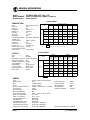
MODEL: . . . . . . . . . . INDY 500 RMK
MODEL NUMBER: . S02SR5AS
ENGINE MODEL: . . S2186--5044PL5A
JETTING CHART
AMBIENT TEMPERATURE
CARBURETION
Type . . . . . . . . . . . . . . . .
Main Jet . . . . . . . . . . . .
Pilot Jet . . . . . . . . . . . . .
Jet Needle . . . . . . . . . . .
Needle Jet . . . . . . . . . . .
Cutaway . . . . . . . . . . . .
Fuel Screw . . . . . . . . . .
Valve Seat . . . . . . . . . . .
Fuel Octane (R+M/2) .
TM38 Mikuni
270
45
9FH4-57-2
P-6
1.5 Notched
0.5 Turns
1.5 Viton
87 Non-Oxygenated
89 Oxygenated
Throttle Gap
Under Cutaway . . . . . . 0.130² (3.3mm)
Starter Jet . . . . . . . . . . . 155
Pilot Air Jet . . . . . . . . . . 0.7 Long
Below -30°F
Below -34°C
34 C
-30_ to --10_F
-34_to
-23_C
-34
to -23
C
--10_to +10_F
-12_C
--23_
23 to --12
C
+10_to +30_F
-12_to
-1_C
-12
to --1
C
+30_to +50_F
+10_C
--1_to
1 to +10
C
Above +50_F
+10_C
Above +10
C
0--600
(0--2000)
440
#3
420
#3
410
#3
390
#3
380
#3
370
#3
600--1200
(2000--4000)
390
#3
380
#3
370
#3
350
#3
340
#2
320
#2
1200--1800
1200
1800
( 000 -6000)
6000)
(4000-
350
#2
330
#2
320
#2
310
#2
300
#2
290
#2
1800--2400
(6000 -8000)
8000)
(6000-
300
#2
290
90
#2
280
80
#2
270
0
#2
260
60
#2
250
50
#2
2400--3000
(8000 -10000)
10000)
(8000-
280
80
#2
270
0
#2
260
60
#2
250
50
#2
240
0
#2
230
30
#2
3000--3700
(10000 -12000)
12000)
(10000-
260
60
#2
250
50
#2
240
0
#2
230
30
#2
220
0
#2
210
0
#2
Altitude
Meters
((Feet))
XXX
#X
- # refers to the clip position from top of jet needle.
CLUTCH
Type . . . . . . . . . . . . . . . .
Belt . . . . . . . . . . . . . . . . .
Belt Width (Projected) .
Side Angle (Overall) . .
Outside Circumference
Center Distance . . . . . .
Shift Weights . . . . . . . .
Primary Spring . . . . . . .
Secondary Spring . . . .
Driven Helix . . . . . . . . .
P-85
3211074
1.438² (36.52mm)
28°
47.625² (121cm)
12.00²
10 Bushed
Almond Round
Silver / Blue
R-32 #3
CLUTCH CHART
DRIVE
Altitude
Meters
(Feet)
DRIVEN
Shift
Weight
Clutch
Spring
Clutch
Spring
Driven
Helix
Chaincase
Gearing
0-900
(0-3000)
10-56
Bushed
Almond
Round
Silver /
Blue
R-32
#3
18-41-68P
HYVO
900-1800
(3000-6000)
10-AL
Bushed
Almond
Round
Silver /
Blue
R-32
#3
18-41-68P
HYVO
1800-2700
(6000-9000)
10
Bushed
Almond
Round
Silver /
Blue
R-32
#3
18-41-68P
HYVO
2700-3700
(9000-12000)
10M
Bushed
Almond
Round
Silver /
Blue
R-32
#3
18-41-68P
HYVO
- Production Setting
ENGINE
Type . . . . . . . . . . . . . . . . . . . . . . .
Displacement . . . . . . . . . . . . . . .
Bore . . . . . . . . . . . . . . . . . . . . . . .
Stroke . . . . . . . . . . . . . . . . . . . . .
Piston / Cylinder Clearance . . .
Service Limit . . . . . . . . . . . . . . . .
Piston Marking . . . . . . . . . . . . . .
Piston Ring Marking . . . . . . . . .
Piston Ring End Gap . . . . . . . .
Head ccs (Uninstalled) . . . . . . .
Head ccs (Installed) . . . . . . . . .
Operating RPM±200 . . . . . . . . .
Idle RPM±200 . . . . . . . . . . . . . .
Engagement RPM±300 . . . . . .
Cylinder Head Torque . . . . . . . .
Cylinder Base Nut Torque . . . .
Crankcase Torque (8mm) . . . . .
Crankcase Torque (10mm) . . .
Flywheel Torque . . . . . . . . . . . . .
1.16
Liquid Cooled Case Reed Twin
500cc
2.776² (70.5mm)
2.520² (64mm)
0.0045² - 0.0063² (0.11 - 0.16mm)
0.0063” (0.16mm)
N/A
N/A
0.012² - 0.018² (0.30 - 0.46mm)
27.5±0.5cc
25.0cc
8000 RPM
1500 RPM
4500 RPM
20-24 ft.lbs. (28-33 Nm)
30-34 ft.lbs. (41-47 Nm)
20-24 ft.lbs. (28-33 Nm)
N/A
90 ft.lbs. (124 Nm)
Fuel Pump Manuf. . . . . .
Fuel Pump Mark . . . . . . .
Oil Pump Manuf. . . . . . . .
Oil Pump Mark . . . . . . . .
Cylinder Head Mark . . . .
Walbro
FPA-3
Mikuni
2540051
3021048
GENERAL INFORMATION
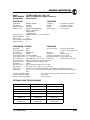
MODEL: . . . . . . . . . . INDY 500 RMK
MODEL NUMBER: . S02SR5AS
ENGINE MODEL: . . S2186--5044PL5A
ELECTRICAL
CAPACITIES
Flywheel I.D. . . . . . .
CDI Marking . . . . . . .
Alternator Output . . .
Ignition Timing . . . . .
Kokusan 4060223
Fuel Tank . . . . . . . . . .
4010259
Oil Tank . . . . . . . . . . . .
280 Watts
Coolant . . . . . . . . . . . .
22° BTDC@3000RPM±1.5°
Chaincase Oil . . . . . . .
0.1139² BTDC (±0.0175²)
2.8927mm BTDC (±0.48mm)
Spark Plug / Gap . . . Champion RN2C / 0.025² (0.64mm)
Voltage Regulator . . LR7
Electric Start . . . . . . . Option
LR7= Full wave voltage regulator
Magneto Pulses . . . . 6
SUSPENSION / CHASSIS
11.8 gallons (44.7 liters)
3 quarts (2.8 liters)
5 quarts (4.7 liters)
9 fl. oz.(266cc)
CHAINCASE
Body Style . . . . . . . .
Front Suspension . .
Front Shocks . . . . . .
IFS Spring Rate . . . .
Front Spring Preload
Front Vertical Travel
Rear Suspension . . .
Rear Axle Travel . . .
Front Track Shock . .
Spring Rate . . . . . . . .
Rear Track Shock . .
Rear Springs . . . . . .
Track Type . . . . . . . .
Track Tension . . . . . .
Gen II
Sprockets / Chain . . . 18-41, 68P HYVO
Indy X-10 38² CRC
Reverse . . . . . . . . . . . . Option
Nitrogen Cell
Brake Pads . . . . . . . . . Type 81, Large
100#/in.
Chaincase Center Dist.7.05² (17.91cm)
1/8² Thread Adjust
Driveshaft Sprockets . 2 Drivers Wide
8.05 in.(21cm)
Brake Type . . . . . . . . . Polaris HPB
XTRA-Lite 136²
12² (30.5cm)
Nitrogen Cell
200#/in. variable
Indy Select
.347² (sq.) / 77°
15²x136²x1.5² (38.1x345.44x3.81cm)
3/8² - 1/2² (1-1.3 cm) slack with 10# (4.54kg) weight 16² (40.64cm) ahead of rear idler
shaft.
Overall Snowmobile Length . . . . . . . . . . . . . . . . . 116² (295cm)
Overall Snowmobile Height . . . . . . . . . . . . . . . . . 45² (114cm)
Maximum Snowmobile Width . . . . . . . . . . . . . . . 43.5² (110.4cm)
OPTIONAL REAR TORSION SPRINGS
(STD)
FIRM
.347²(Sq.) Diameter x 77°
.375” (Sq.) Diameter x 77_
_
L.H. 7041627--067
L.H. 7041631--067
R.H 7041628--067
R.H. 7041632--067
1.17
GENERAL INFORMATION
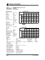
MODEL: . . . . . . . . . . INDY TRAIL RMK
MODEL NUMBER: . S02SR5BS
ENGINE MODEL: . . EC55PM024
JETTING CHART
AMBIENT TEMPERATURE
CARBURETION
Type . . . . . . . . . . . . . . . . VM34SS Mikuni
w/ACCS
Main Jet . . . . . . . . . . . . 270
Pilot Jet . . . . . . . . . . . . . 35
Jet Needle . . . . . . . . . . . 6DEH11-3
Needle Jet . . . . . . . . . . . Q-0 (480)
Cutaway . . . . . . . . . . . . 3.0
Air Screw . . . . . . . . . . . 1.5 Turns
Valve Seat . . . . . . . . . . . 1.5 Viton
Fuel Octane (R+M/2) . 87 Non-Oxygenated
Throttle Gap
89 Oxygenated
Under Cutaway . . . . . . .218² (5.54mm)
Below -30°F
Below -34°C
34 C
-30_ to --10_F
-34_to
-23_C
-34
to -23
C
--10_to +10_F
-12_C
--23_
23 to --12
C
+10_to +30_F
-12_to
-1_C
-12
to --1
C
+30_to +50_F
+10_C
--1_to
1 to +10
C
Above +50_F
+10_C
Above +10
C
0--600
(0--2000)
300
#3
290
#3
280
#3
270
#3
260
#3
250
#3
600--1200
(2000--4000)
300
#3
290
#3
280
#3
270
#3
260
#3
250
#3
1200--1800
1200
1800
( 000 -6000)
6000)
(4000-
300
#3
290
#3
280
#3
270
#3
260
#3
250
#3
1800--2400
(6000 -8000)
8000)
(6000-
300
#3
290
90
#3
280
80
#3
270
0
#3
260
60
#3
250
50
#3
2400--3000
(8000 -10000)
10000)
(8000-
300
#3
290
90
#3
280
80
#3
270
0
#3
260
60
#3
250
50
#3
3000--3700
(10000 -12000)
12000)
(10000-
300
#3
290
90
#3
280
80
#3
270
0
#3
260
60
#3
250
50
#3
Altitude
Meters
((Feet))
XXX
#X
- # refers to the clip position from top of jet needle.
CLUTCH
Type . . . . . . . . . . . . . . . .
Belt . . . . . . . . . . . . . . . . .
Belt Width (Projected) .
Side Angle (Overall) . .
Outside Circumference
Center Distance . . . . . .
Shift Weights . . . . . . . .
Primary Spring . . . . . . .
Secondary Spring . . . .
Driven Helix . . . . . . . . .
P-85
3211070
1.375² (34.93)
28°
47.250² (120cm)
12.00²
10-56 Bushed
Dark Blue / White
Silver / Blue
R-32 #2
CLUTCH CHART
DRIVE
Altitude
Meters
(Feet)
DRIVEN
Shift
Weight
Clutch
Spring
Clutch
Spring
Driven
Helix
Chaincase
Gearing
0-900
(0-3000)
10-62
Bushed
Dark Blue /
White
Silver/
Blue
R-32
#2
18-41-68P
HYVO
900-1800
(3000-6000)
10-58
Bushed
Dark Blue /
White
Silver/
Blue
R-32
#2
18-41-68P
HYVO
1800-2700
(6000-9000)
10-56
Bushed
Dark Blue /
White
Silver/
Blue
R-32
#2
18-41-68P
HYVO
2700-3700
(9000-12000)
10-54
Bushed
Dark Blue /
White
Silver/
Blue
R-32
#2
18-41-68H
YVO
- Production Setting
ENGINE
Type . . . . . . . . . . . . . . . . . . . . . . .
Displacement . . . . . . . . . . . . . . .
Bore . . . . . . . . . . . . . . . . . . . . . . .
Stroke . . . . . . . . . . . . . . . . . . . . .
Piston / Cylinder Clearance . . .
Service Limit . . . . . . . . . . . . . . . .
Piston Marking . . . . . . . . . . . . . .
Piston Ring Marking . . . . . . . . .
Piston Ring End Gap . . . . . . . .
Head ccs (Uninstalled) . . . . . . .
Head ccs (Installed) . . . . . . . . .
Operating RPM±200 . . . . . . . . .
Idle RPM±200 . . . . . . . . . . . . . .
Engagement RPM±300 . . . . . .
Cylinder Head Torque . . . . . . . .
Cylinder Base Nut Torque . . . .
Crankcase Torque (8mm) . . . . .
Crankcase Torque (10mm) . . .
Flywheel Torque . . . . . . . . . . . . .
1.18
Fan Cooled Reed Assist Twin
544cc
2.874² (73mm)
2.559² (65mm)
0.0035² - 0.0049² (0.09 - 0.125mm)
0.0078² (0.20mm)
5MB
N
0.016² - 0.022² (0.40 - 0.55mm)
33.8±0.4cc
27.7cc
6800 RPM
1600 RPM
3800 RPM
18-19.5 ft.lbs. (25-27 Nm)
24-28 ft.lbs. (33-39 Nm)
16.6-18 ft.lbs. (23-35 Nm)
N/A
60-65 ft.lbs. (83-90 Nm)
Fuel Pump Manuf. . . . . .
Fuel Pump Mark . . . . . . .
Oil Pump Manuf. . . . . . . .
Oil Pump Mark . . . . . . . .
Cylinder Head Mark . . . .
Taiyo
FJP-3-100
Mikuni
55MB
EC55PM
GENERAL INFORMATION
MODEL: . . . . . . . . . . INDY TRAIL RMK
MODEL NUMBER: . S02SR5BS
ENGINE MODEL: . . EC55PM024
ELECTRICAL
CAPACITIES
Flywheel I.D. . . . . . .
CDI Marking . . . . . . .
Alternator Output . . .
Ignition Timing . . . . .
Mitsubishi
17620111
240 Watts
27° BTDC@3500RPM±1.5°
0.175² BTDC (±0.157² - 0.195²)
4.45mm BTDC (±3.97 - 4.93mm)
Spark Plug / Gap . . . NGK BR9ES / 0.028² (0.7mm)
Voltage Regulator . . LR7
Electric Start . . . . . . . Option
LR7= Full wave voltage regulator
Magneto Pulses . . . . 6
Fuel Tank . . . . . . . . . .
Oil Tank . . . . . . . . . . . .
Coolant . . . . . . . . . . . .
Chaincase Oil . . . . . . .
SUSPENSION / CHASSIS
CHAINCASE
11.8 gallons (44.7 liters)
3 quarts (2.8 liters)
N/A
9 fl. oz.(266cc)
Body Style . . . . . . . .
Front Suspension . .
Front Shocks . . . . . .
IFS Spring Rate . . . .
Front Spring Preload
Front Vertical Travel
Rear Suspension . . .
Rear Axle Travel . . .
Front Track Shock . .
Spring Rate . . . . . . . .
Rear Track Shock . .
Rear Springs . . . . . .
Track Type . . . . . . . .
Track Tension . . . . . .
Gen II
Sprockets / Chain . . . 18-41, 68P HYVO
Indy XTRA 38²
Reverse . . . . . . . . . . . . Option
Nitrogen Cell
Brake Pads . . . . . . . . . Type 81, Small
80#/in.
Chaincase Center Dist.7.05² (17.9cm)
5/16² Thread Adjust
Driveshaft Sprockets . 2 Drivers
8.25² (21cm)
Brake Type . . . . . . . . . Polaris HPB
XTRA-Lite 136²
12² (30.5cm)
Nitrogen Cell
181#/in.
Indy Select
.347² (sq.) / 77°
15²x136²x.1.25² (38.1x345.44x3.175cm)
3/8² - 1/2² (1-1.3 cm) slack with 10# (4.54kg) weight 16² (40.64cm) ahead of rear idler
shaft.
Overall Snowmobile Length . . . . . . . . . . . . . . . . . 116² (295cm)
Overall Snowmobile Height . . . . . . . . . . . . . . . . . 45² (114cm)
Maximum Snowmobile Width . . . . . . . . . . . . . . . 43.5² (110.5cm)
OPTIONAL REAR TORSION SPRINGS
SOFT
MEDIUM(STD)
FIRM
.347²(Sq.) Diameter x 77°
.375”(Sq.) Diameter x 77°
L.H .
L.H. 7041627--067
L.H. 7041631--067
R.H.
R.H. 7041628--067
R.H. 7041632--067
1.19
GENERAL INFORMATION
MODEL: . . . . . . . . . . 600 EDGE RMK
MODEL NUMBER: . S02NJ6ES
ENGINE MODEL: . . S2187--6044PL6E
JETTING CHART
CARBURETION
Type . . . . . . . . . . . . . . . .
Main Jet . . . . . . . . . . . .
Pilot Jet . . . . . . . . . . . . .
Jet Needle . . . . . . . . . . .
Needle Jet . . . . . . . . . . .
Cutaway . . . . . . . . . . . .
Fuel Screw . . . . . . . . . .
Valve Seat . . . . . . . . . . .
Fuel Octane (R+M/2) .
Throttle Gap
Under Cutaway . . . . . .
Starter Jet . . . . . . . . . . .
Pilot Air Jet . . . . . . . . . .
Exhaust Spring
Low Elevation Exhaust
Valve Spring . . . . . . . . .
TM 38 w/TPS Mikuni
310
45
9DGI1--60--2
P-8 (825)
1.5 Notched
2.0 Turns
1.5
Key Switch Adj.
Premium 91
Regular 87 Non-Oxy.
0.102² (2.6mm)
140
N/A
Green/White
Pink
-30_ to --10_F
-34_to
-23_C
-34
to -23
C
--10_to +10_F
-12_C
--23_
23 to --12
C
+10_to +30_F
-12_to
-1_C
-12
to --1
C
+30_to +50_F
+10_C
--1_to
1 to +10
C
Above +50_F
+10_C
Above +10
C
0--600
(0--2000)
450
#4
430
#4
420
#3
400
#3
380
#3
370
#3
600--1200
(2000--4000)
410
#4
390
#3
380
#3
360
#3
340
#3
330
#2
Meters
((Feet))
1200--1800
1200
1800
( 000 -6000)
6000)
(4000-
380
#3
360
#3
350
#3
330
#3
320
#2
300
#2
1800--2400
(6000 -8000)
8000)
(6000-
360
#3
430
#3
320
#3
310
#2
290
#2
280
#2
2400--3000
(8000 -10000)
10000)
(8000-
340
3
0
#3
320
3
0
#3
300
#2
290
90
#2
270
0
#2
260
60
#2
3000--3700
(10000 -12000)
12000)
(10000-
330
#2
310
3
0
#2
290
90
#2
280
80
#2
260
60
#2
240
0
#2
XXX
#X
- # refers to the clip position from top of jet needle.
CLUTCH CHART
CLUTCH
Type . . . . . . . . . . . . . . . .
Belt . . . . . . . . . . . . . . . . .
Belt Width (Projected) .
Side Angle (Overall) . .
Outside Circumference
Center Distance . . . . . .
Shift Weights . . . . . . . .
Primary Spring . . . . . . .
Secondary Spring . . . .
Driven Helix . . . . . . . . .
AMBIENT TEMPERATURE
Below -30°F
Below -34°C
34 C
Altitude
DRIVE
P-85
3211080
1.438² (36.53mm)
28°
48.375² (122.87cm)
11.5²
10-56 Bushed
Black/Green
Silver / Blue
R-32#3
Altitude
Meters
(Feet)
DRIVEN
Shift
Weight
Clutch
Spring
Clutch
Spring
Driven
Helix
Chaincase
Gearing
0-900
(0-3000)
10-60
Bushed
Black/
Green
Silver /
Blue
R-32
#3
19-39 72P
HYVO
900-1500
(3000-6000)
10-58
Bushed
Black/
Green
Silver /
Blue
R-32
#3
19-39 72P
HYVO
1500-2100
(6000-9000)
10-56
Bushed
Black/
Green
Silver /
Blue
R-32
#3
19-39 72P
HYVO
2100-2700
(7000-9000)
10 54
Bushed
Black/
Green
Silver /
Blue
R-32
#3
19-39 72P
HYVO
2700-3350
(9000-11000)
10AL
Bushed
Black/
Green
Silver /
Blue
R-32
#3
19-39 72P
HYVO
3350--4000
(11000-13000)
10
Bushed
Black/
Green
Silver /
Blue
R-32
#3
19-39 72P
HYVO
- Production Setting
ENGINE
Type . . . . . . . . . . . . . . . . . . . . . . .
Displacement . . . . . . . . . . . . . . .
Bore . . . . . . . . . . . . . . . . . . . . . . .
Stroke . . . . . . . . . . . . . . . . . . . . .
Piston / Cylinder Clearance . . .
Service Limit . . . . . . . . . . . . . . . .
Piston Marking . . . . . . . . . . . . . .
Piston Ring Marking . . . . . . . . .
Piston Ring End Gap . . . . . . . .
Head ccs (Uninstalled) . . . . . . .
Head ccs (Installed) . . . . . . . . .
Operating RPM±200 . . . . . . . . .
Idle RPM±200 . . . . . . . . . . . . . .
Engagement RPM±300 . . . . . .
Cylinder Head Torque . . . . . . . .
Cylinder Base Nut Torque . . . .
Crankcase Torque (8mm) . . . . .
Crankcase Torque (10mm) . . .
1.20
Liquid Cooled Case Reed w/TPS
593cc
2.9930² 3.041² (77.25mm)
2.520 (64mm)
0.0044² - 0.0058² (0.11 - 0.15mm)
.0059” (0.15mm)
3021088
N/A
0.012² - 0.018² (0.30 - 0.46mm)
36.0cc
29.0cc
8000 RPM
1500 RPM
N/A RPM
18-22 ft.lbs. (25-30 Nm)
30-34 ft.lbs. (41-47 Nm)
20-24 ft.lbs. (28-33 Nm)
26-30 ft.lbs. (36-41 Nm)
Fuel Pump Manuf. . . . . .
Fuel Pump Mark . . . . . . .
Oil Pump Manuf. . . . . . . .
Oil Pump Mark . . . . . . . .
Cylinder Head Mark . . . .
Walbro
N/A
Mikuni
2540097
3022057
GENERAL INFORMATION
MODEL: . . . . . . . . . . 600 EDGE RMK
MODEL NUMBER: . S02NJ6ES
ENGINE MODEL: . . S2187--6044PL6E
ELECTRICAL
Flywheel I.D. . . . . . .
CDI Marking . . . . . . .
Alternator Output . . .
Ignition Timing . . . . .
Spark Plug / Gap . . .
Voltage Regulator . .
Electric Start . . . . . . .
Magneto Pulses . . . .
CAPACITIES
4010629
Fuel Tank . . . . . . . . . .
4010554
Oil Tank . . . . . . . . . . . .
280 Watts
Coolant . . . . . . . . . . . .
24_@3500RPM±500°
Chaincase Oil . . . . . . .
With TPS Unplugged.
.1350² BTDC
3.43mm BTDC
Champion RN57YCC / 0.025² (0.64mm)
T1
Option
6
SUSPENSION / CHASSIS
11.8 gallons (44.7 liters)
3.25 quarts (3.07 liters)
4.3 quarts (4.07 liters)
11 fl. oz.(325cc)
CHAINCASE
Body Style . . . . . . . .
Front Suspension . .
Front Shocks . . . . . .
IFS Spring Rate . . . .
Front Spring Preload
Front Vertical Travel
Rear Suspension . . .
Rear Axle Travel . . .
Front Track Shock . .
Spring Rate . . . . . . . .
Rear Track Shock . .
Rear Springs . . . . . .
Track Type . . . . . . . .
Track Tension . . . . . .
EDGE RMK
Sprockets / Chain . . . 19-39 72P HYVO
EDGE RMK
Reverse . . . . . . . . . . . . Option
Nitrex
Brake Pads . . . . . . . . . Type 81, Large
100#/in.
Chaincase Center Dist.7.92² (20.12cm)
3/4² Thread Adjust
Driveshaft Sprockets . 2 Drivers Wide, XHS
7.2² - 7.6² (18.3 - 19.3cm)
Brake Type . . . . . . . . . Polaris HPB Liquid Cooled
EDGE RMK
13.8² (35cm)
Nitrex
170#/in.
Indy Select
.375² (sq.) / 77°
15²x136²x1.75² (38.1x345.44x4.45cm)
3/8² - 1/2² (1-1.3 cm) slack with 10# (4.54kg) weight 16² (40.64cm) ahead of rear idler
shaft.
Overall Snowmobile Length . . . . . . . . . . . . . . . . . 102.5² (306cm)
Overall Snowmobile Height . . . . . . . . . . . . . . . . . 47.5² (120.7cm)
Maximum Snowmobile Width . . . . . . . . . . . . . . . 47.25² (120cm)
OPTIONAL REAR TORSION SPRINGS
SOFT
--
(STD)
FIRM
.347²²(Sq.) Diameter x 77°° .359²²(Sq.) Diameter x 77°°
N/A
L.H.(136” ) 7041627--067
L.H.(136”) 7041629--067
N/A
R.H.(136”) 7041628--067
R.H.(136”) 7041630--067
.347²²(Sq.) Diameter x 47°° .359²²(Sq.) Diameter x 47°° .375²²(Sq.) Diameter x 47°°
L.H.(144”/151”)
7042081--067
L.H.(144”/151”)
7042068--067
L.H.(144”/151”)
7042079--067
R.H.(144”/151”)
7042082--067
R.H.(144”/151”)
7042069--067
R.H.(144”/151”)
7042080--067
1.21
GENERAL INFORMATION
MODEL: . . . . . . . . . . INDY 700 SKS / (EUROPEAN MODEL)
MODEL NUMBER: . S02SS7CS / (E02SS7CE)
ENGINE MODEL: . . S2189--7070PL7C
JETTING CHART
AMBIENT TEMPERATURE
CARBURETION
Type . . . . . . . . . . . . . . . .
Main Jet . . . . . . . . . . . .
Pilot Jet . . . . . . . . . . . . .
Jet Needle . . . . . . . . . . .
Needle Jet . . . . . . . . . . .
Cutaway . . . . . . . . . . . .
Air Screw . . . . . . . . . . .
Valve Seat . . . . . . . . . . .
Fuel Octane (R+M/2) .
Throttle Gap
Under Cutaway . . . . . .
Starter Jet . . . . . . . . . . .
Pilot Air Jet . . . . . . . . . .
Exhaust Valve Spring .
TM40 Mikuni
420
38
9DFH10--57 / 3
P--8
1.5
N/A
1.8
87 Non-Oxygenated
89 Oxygenated
Type . . . . . . . . . . . . . . . .
Belt . . . . . . . . . . . . . . . . .
Belt Width (Projected) .
Side Angle (Overall) . .
Outside Circumference
Center Distance . . . . . .
Shift Weights . . . . . . . .
Primary Spring . . . . . . .
Secondary Spring . . . .
Driven Helix . . . . . . . . .
Meters
((Feet))
(2.0mm)
145
1.1Long
Green/Yellow
CLUTCH
P-85
3211065
1.438² (3.63cm)
28°
48.375² (122.87cm)
12.50²
10-58 Bushed
Black/Green
Silver / Blue
R8 #2
Below -30°F
Below -34°C
34 C
-30_ to --10_F
-34_to
-23_C
-34
to -23
C
--10_to +10_F
-12_C
--23_
23 to --12
C
+10_to +30_F
-12_to
-1_C
-12
to --1
C
+30_to +50_F
+10_C
--1_to
1 to +10
C
Above +50_F
+10_C
Above +10
C
0--600
(0--2000)
450
#3
440
#3
420
#3
400
#3
390
#2
370
#2
600--1200
(2000--4000)
430
#3
410
#3
390
#3
380
#3
360
#2
340
#2
1200--1800
1200
1800
( 000 -6000)
6000)
(4000-
400
#3
390
#3
370
#3
350
#2
340
#2
320
#1
1800--2400
(6000 -8000)
8000)
(6000-
380
#3
360
#3
340
3
0
#2
330
#2
310
3
0
#1
290
90
#1
2400--3000
(8000 -10000)
10000)
(8000-
350
#3
340
3
0
#2
320
3
0
#2
300
#1
290
90
#1
270
0
#1
3000--3700
(10000 -12000)
12000)
(10000-
330
#2
310
3
0
#2
290
90
#1
280
80
#1
260
60
#1
240
0
#1
Altitude
XXX
#X
- # refers to the clip position from top of jet needle.
CLUTCH CHART
DRIVE
Shift
Weight
Clutch
Spring
Clutch
Spring
Driven
Helix
Chaincase
Gearing
Chaincase
Gearing
European
0-900
(0-3000)
10-58
Bushed
Black /
Green
Silver /
Blue
R8
#2
23-40-70P
HYVO
23 40 70P
23-40-70P
HYVO
900-1800
(3000-6000)
10-56
Bushed
Black /
Green
Silver /
Blue
R8
#2
23-40-70P
HYVO
23 40 70P
23-40-70P
HYVO
1800-2700
(6000-9000)
10-54
Bushed
Black /
Green
Silver /
Blue
R8
#2
21-41-70P
HYVO
21 41 70P
21-41-70P
HYVO
2700-3700
(9000-12000)
10-AL
Bushed
Black /
Green
Silver /
Blue
R8
#2
21-41-70P
HYVO
21 41 70P
21-41-70P
HYVO
Altitude
Meters
(Feet)
DRIVEN
- Production Setting
ENGINE
Type . . . . . . . . . . . . . . . . . . . . . . .
Displacement . . . . . . . . . . . . . . .
Bore . . . . . . . . . . . . . . . . . . . . . . .
Stroke . . . . . . . . . . . . . . . . . . . . .
Piston / Cylinder Clearance . . .
Service Limit . . . . . . . . . . . . . . . .
Piston Marking . . . . . . . . . . . . . .
Piston Ring Marking . . . . . . . . .
Piston Ring End Gap . . . . . . . .
Head ccs (Uninstalled) . . . . . . .
Head ccs (Installed) . . . . . . . . .
Operating RPM±200 . . . . . . . . .
Idle RPM±200 . . . . . . . . . . . . . .
Engagement RPM±300 . . . . . .
Cylinder Head Torque . . . . . . . .
Cylinder Base Nut Torque . . . .
Crankcase Torque (8mm) . . . . .
Crankcase Torque (10mm) . . .
Flywheel Torque . . . . . . . . . . . . .
1.22
Liquid Cooled Case Reed Twin
701cc
3.1889² (81mm)
2.6772² (68mm)
0.0044² - 0.0058² (0.11 - 0.15mm)
0.0060”
3021041
N/A
0.014² - 0.020² (.36 - .51mm)
37.5±.50cc
33.5cc
8250 RPM
1500 RPM
4000 RPM
18-22 ft.lbs. (25-30 Nm)
30-34 ft.lbs. (41-47 Nm)
20-24 ft.lbs. (28-33 Nm)
26-30 ft.lbs. (36-42 Nm)
90 ft.lbs. (124 Nm)
Fuel Pump Manuf. . . . . .
Fuel Pump Mark . . . . . . .
Oil Pump Manuf. . . . . . . .
Oil Pump Mark . . . . . . . .
Cylinder Head Mark . . . .
Walbro
FPA-4
Mikuni
03A
3021022
GENERAL INFORMATION
MODEL: . . . . . . . . . . INDY 700 SKS / (EUROPEAN MODEL)
MODEL NUMBER: . S02SS7CS / (E02SS7CE)
ENGINE MODEL: . . S2189--7070PL7C
ELECTRICAL
CAPACITIES
Flywheel I.D. . . . . . .
CDI Marking . . . . . . .
Alternator Output . . .
Ignition Timing . . . . .
4010523
Fuel Tank . . . . . . . . . .
4010587
Oil Tank . . . . . . . . . . . .
280 Watts
Coolant . . . . . . . . . . . .
18° @3000RPM±500
Chaincase Oil . . . . . . .
0.0815² BTDC
2.075mm BTDC
Spark Plug / Gap . . . Champion RN57YCC / 0.025² (0.64mm)
Voltage Regulator . . LR7
Electric Start . . . . . . . Option
LR7= Full wave voltage regulator
Magneto Pulses . . . . 6
SUSPENSION / CHASSIS
11.8 gallons (44.7 liters)
3 quarts (2.8 liters)
5.5 / 6 quarts (5.2 / 5.7 liters)
9 / 11 fl. oz.(266 / 325cc)
CHAINCASE
Body Style . . . . . . . .
Front Suspension . .
Front Shocks . . . . . .
IFS Spring Rate . . . .
Front Spring Preload
Front Vertical Travel
Rear Suspension . . .
Rear Axle Travel . . .
Front Track Shock . .
Spring Rate . . . . . . . .
Rear Track Shock . .
Rear Springs . . . . . .
Track Type . . . . . . . .
Track Tension . . . . . .
Gen II
Sprockets / Chain . . . 23-40-70P HYVO
Indy XC 10
Reverse . . . . . . . . . . . . Option
Indy Select
Brake Pads . . . . . . . . . Type 81, Large
100#/in.
Chaincase Center Dist.7.05² (17.91cm)
3/4² Thread Adjust
Driveshaft Sprockets . 2 Drivers Wide
9.6² (24.4cm)
Brake Type . . . . . . . . . Polaris HPB, Liquid Cooled
XTRA-10 136², (XTRA 10 European)
9.5 in.(24.1cm)
Nitrogen Cell
200#/in. variable
Indy Select
.359² (sq.) / 77°
15²x136²x1.25² (38.1x345.44x3.175cm)
3/8² - 1/2² (1-1.3 cm) slack with 10# (4.54kg) weight 16² (40.64cm) ahead of rear idler
shaft.
Overall Snowmobile Length . . . . . . . . . . . . . . . . . 116² (295cm)
Overall Snowmobile Height . . . . . . . . . . . . . . . . . 45² (114cm)
Maximum Snowmobile Width . . . . . . . . . . . . . . . 48² (122cm)
OPTIONAL REAR TORSION SPRINGS (700 SKS)
SOFT
MEDIUM(STD)
FIRM
.347”(Sq.) Diameter x 77_
_
.359²(Sq.) Diameter x 77_
.405”(Sq.) Diameter x 77_
L.H. 7041627--067
L.H. 7041629--067
L.H. 7041655--067
R.H. 7041628--067
R.H. 7041630--067
R.H. 7041656--067
1.23
GENERAL INFORMATION
MODEL: . . . . . . . . . . 700 EDGE RMK 136”, 144”, 151”
MODEL NUMBER: . S02NJ7CS, S02NK7CSA, S02NK7CS, S02NL7CS
ENGINE MODEL: . . S2190--7070PL7C
JETTING CHART
CARBURETION
Type . . . . . . . . . . . . . . . .
Main Jet . . . . . . . . . . . .
Pilot Jet . . . . . . . . . . . . .
Jet Needle . . . . . . . . . . .
Needle Jet . . . . . . . . . . .
Cutaway . . . . . . . . . . . .
Air Screw . . . . . . . . . . .
Valve Seat . . . . . . . . . . .
Fuel Octane (R+M/2) .
Throttle Gap
Under Cutaway . . . . . .
Starter Jet . . . . . . . . . . .
Pilot Air Jet . . . . . . . . . .
Fuel Screw . . . . . . . . . .
Exhaust Valve Spring
Low Elevation Exhaust
Valve Spring . . . . . . . . .
TM 40 w/TPS Mikuni
350
45
9DGJ2--57--2
P-8 (825)
2.0
1.0 Turns
1.8
Key Switch Adjustable
-30_ to --10_F
-34 to -23_C
-23 C
-34_to
--10_to +10_F
-23 to --12_C
-12 C
-23_
+10_to +30_F
-12 to --1_C
-1 C
-12_to
+30_to +50_F
+10 C
-1 to +10_C
-1_to
Above +50_F
+10 C
Above +10_C
0--600
(0--2000)
490
#4
480
#4
460
#3
440
#3
420
#3
400
#3
600--1200
(2000--4000)
470
#4
450
#3
430
#3
410
#3
390
#3
380
#2
1200 -1800
1800
1200((4000000 -6000)
6000)
440
#3
420
#3
400
#3
380
#3
370
#2
350
#2
1800--2400
(6000--8000)
(6000
8000)
0
410
#3
390
#3
3 0
370
#3
350
#2
3 0
340
#2
3 0
320
#2
2400--3000
(8000--10000)
(8000
10000)
380
#3
360
#3
3 0
340
#2
3 0
320
#2
3 0
310
#2
90
290
#2
3000--3700
(10000--12000)
(10000
12000)
350
#3
330
#2
3 0
320
#2
300
#2
80
280
#2
60
260
#2
Altitude
Meters
(
)
(Feet)
0.984² (2.5mm)
145
0.9 Long
2.0 Turns out
Orange
XXX
#X
- # refers to the clip position from top of jet needle.
Green/Yellow
CLUTCH CHART
CLUTCH
Type . . . . . . . . . . . . . . . .
Belt . . . . . . . . . . . . . . . . .
Belt Width (Projected) .
Side Angle (Overall) . .
Outside Circumference
Center Distance . . . . . .
Shift Weights . . . . . . . .
Primary Spring . . . . . . .
Secondary Spring . . . .
Driven Helix . . . . . . . . .
AMBIENT TEMPERATURE
Below -30°F
34 C
Below -34°C
P-85
3211080
1.438² (36.53mm)
28°
46.625²
11.5²
10-56 Bushed
Black/Green
Silver / Blue
R-8 #3
DRIVE
Shift
Weight
Clutch
Spring
Clutch
Spring
Driven
Helix
Chaincase
Gearing
(136”)
Chaincase
Gearing
(144”,151”)
0-900
(0-3000)
10--62
Bushed
Black /
Green
Silver /
Blue
R-8
#3
21--41 74P
HYVO
19 39 72P
19-39
HYVO
900-1500
(3000-5000)
10--60
Bushed
Black /
Green
Silver /
Blue
R-8
#3
21--41 74P
HYVO
19 39 72P
19-39
HYVO
1500-2100
(5000-7000)
10-58
Bushed
Black /
Green
Silver /
Blue
R-8
#3
21--41 74P
HYVO
19 39 72P
19-39
HYVO
2100-2700
(7000-9000)
10-56
Bushed
Black /
Green
Silver /
Blue
R-8
#3
21--41 74P
HYVO
19 39 72P
19-39
HYVO
2700--3350
(9000--11000)
10--54
Bushed
Black /
Green
Silver /
Blue
R-8
#3
21--41 74P
HYVO
19-39 72P
HYVO
3350--4000
(11000--13000)
10--AL
Bushed
Black /
Green
Silver /
Blue
R-8
#3
21--41 74P
HYVO
19-39 72P
HYVO
Altitude
Meters
((Feet))
DRIVEN
- Production Setting
ENGINE
Type . . . . . . . . . . . . . . . . . . . . . . .
Displacement . . . . . . . . . . . . . . .
Bore . . . . . . . . . . . . . . . . . . . . . . .
Stroke . . . . . . . . . . . . . . . . . . . . .
Piston / Cylinder Clearance . . .
Service Limit . . . . . . . . . . . . . . . .
Piston Marking . . . . . . . . . . . . . .
Piston Ring Marking . . . . . . . . .
Piston Ring End Gap . . . . . . . .
Head ccs (Uninstalled) . . . . . . .
Head ccs (Installed) . . . . . . . . .
Operating RPM±200 . . . . . . . . .
Idle RPM±200 . . . . . . . . . . . . . .
Engagement RPM±300 . . . . . .
Cylinder Head Torque . . . . . . . .
Cylinder Base Nut Torque . . . .
Crankcase Torque (8mm) . . . . .
1.24
Liquid Cooled Case Reed w/TPS
701cc
3.1889² (81mm)
2.6772² (68mm)
0.0043² - 0.0057² (0.11 -- 0.14mm)
.0058”
3021041
N/A
0.014² - 0.020² (0.36 - 0.51mm)
37.2±.50cc
33.5 -- 34.5cc
8100 RPM
1500 RPM
3900 RPM
18-22 ft.lbs. (25-30 Nm)
30-34 ft.lbs. (41-47 Nm)
20-24 ft.lbs. (28-33 Nm)
Fuel Pump Manuf. . . . . .
Fuel Pump Mark . . . . . . .
Oil Pump Manuf. . . . . . . .
Oil Pump Mark . . . . . . . .
Cylinder Head Mark . . . .
Walbro
FPA-4
Mikuni
03A
3021022
Flywheel Torque90 ft.lbs. (124 Nm)
GENERAL INFORMATION
MODEL: . . . . . . . . . . 700 EDGE RMK 136”, 144”, 151”
MODEL NUMBER: . S02NJ7CS, S02NK7CSA, S02NK7CS, S02NL7CS
ENGINE MODEL: . . S2190--7070PL7C
ELECTRICAL
CAPACITIES
Flywheel I.D. . . . . . .
CDI Marking . . . . . . .
Alternator Output . . .
Ignition Timing . . . . .
Kokusan 4010629
Fuel Tank . . . . . . . . . .
4010553
Oil Tank . . . . . . . . . . . .
280 Watts
Coolant . . . . . . . . . . . .
18° BTDC@2500RPM±500
Chaincase Oil . . . . . . .
With TPS Unplugged.
0.0815² BTDC
2.0705mm BTDC
Spark Plug / Gap . . . Champion RN57YCC / 0.025² (0.64mm)
Voltage Regulator . . LR7
Electric Start . . . . . . . Option
LR7= Full wave voltage regulator
Magneto Pulses . . . . 6
SUSPENSION / CHASSIS
11.8 gallons (44.7 liters)
3.25 quarts (3.1 liters)
4.3 quarts (4.1 liters)
11 fl. oz.(325cc)
CHAINCASE
Body Style . . . . . . . .
Front Suspension . .
Front Shocks . . . . . .
IFS Spring Rate . . . .
Front Spring Preload
Front Vertical Travel
Rear Suspension . . .
Rear Axle Travel . . .
Front Track Shock . .
Spring Rate . . . . . . . .
Rear Track Shock . .
Rear Springs . . . . . .
Track Type . . . . . . . .
Track Tension . . . . . .
EDGE
Sprockets / Chain . . . 21--41 74P HYVO(136)
EDGE
19--39 72P HYVO (144, 151)
Nitrogen Cell
Reverse . . . . . . . . . . . . Option
100#/in.
Brake Pads . . . . . . . . . Type 81, Large
3/4² Thread Adjust
Chaincase Center Dist.7.05² (17.91cm)
7.2² - 7.6² (18.3 - 19.3cm)
Driveshaft Sprockets . 2 Drivers Wide, XHS
EDGE RMK 136”, 144² or 151”
Brake Type . . . . . . . . . Polaris HPB Liquid Cooled
13.8² (35cm)--(136), 17”(43cm)--(144, 151)
Nitrex (136, 144), Ryde FX IFP (151)
170#/in.
Indy Select (136, 144) Ryde FX IFP (151)
.347”sq./47° (136), .359² (sq.) / 77°(144, 151)
15²x136²x1.75² (38.1x345.44x4.44cm) or 15²x144²x2.0² (38.1x365.76x5.08cm)
3/8² - 1/2² (1-1.3 cm) slack with 10# (4.54kg) weight 16² (40.64cm) ahead of rear idler
shaft.
Overall Snowmobile Length . . . . . . . . . . . . . . . . . 136² Track= 116² (295cm) 144² Track= 119.75² (304.2cm)
Overall Snowmobile Height . . . . . . . . . . . . . . . . . 45² (114cm)
Maximum Snowmobile Width . . . . . . . . . . . . . . . 44.25² (122cm)
OPTIONAL REAR TORSION SPRINGS
SOFT
--
(STD)
FIRM
.347²²(Sq.) Diameter x 77°° .359²²(Sq.) Diameter x 77°°
N/A
L.H.(136” ) 7041627--067
L.H.(136”) 7041629--067
N/A
R.H.(136”) 7041628--067
R.H.(136”) 7041630--067
.347²²(Sq.) Diameter x 47°° .359²²(Sq.) Diameter x 47°° .375²²(Sq.) Diameter x 47°°
L.H.(144”/151”)
7042081--067
L.H.(144”/151”)
7042068--067
L.H.(144”/151”)
7042079--067
R.H.(144”/151”)
7042082--067
R.H.(144”/151”)
7042069--067
R.H.(144”/151”)
7042080--067
1.25
GENERAL INFORMATION
MODEL: . . . . . . . . . . 800 EDGE RMK 144”, 151”, 156”
MODEL NUMBER: . S02NM8CS
ENGINE MODEL: . . S2188--8070PL8C
JETTING CHART
CARBURETION
Type . . . . . . . . . . . . . . . .
Main Jet . . . . . . . . . . . .
Pilot Jet . . . . . . . . . . . . .
Jet Needle . . . . . . . . . . .
Needle Jet . . . . . . . . . . .
Cutaway . . . . . . . . . . . .
Fuel Screw . . . . . . . . . .
Air Screw
Valve Seat . . . . . . . . . . .
Fuel Octane (R+M/2) .
Throttle Gap
Under Cutaway . . . . . .
Starter Jet . . . . . . . . . . .
Pilot Air Jet . . . . . . . . . .
Exhaust Valve Spring .
Low Elevation Exhaust
Valve Spring . . . . . . . . .
TM 40 w/ TPS
390
45
9DGJ3--57/2
P-8 (825)
2.0
2.0 Turn
1.0 Turn
1.8
Key Switch Adj.
91 Premium
89 Regular
AMBIENT TEMPERATURE
Below -30°F
Below -34°C
34 C
-30_ to --10_F
-34_to
-23_C
-34
to -23
C
--10_to +10_F
-12_C
--23_
23 to --12
C
+10_to +30_F
-12_to
-1_C
-12
to --1
C
+30_to +50_F
+10_C
--1_to
1 to +10
C
Above +50_F
+10_C
Above +10
C
0--600
(0--2000)
560N
#4
540N
#4
520N
#4
500
#4
480
#3
460
#3
600--1200
(2000--4000)
520N
#4
500
#4
480
#4
460
#3
440
#2
420
#2
1200--1800
1200
1800
( 000 -6000)
6000)
(4000-
490
#4
470
#4
450
#3
430
#3
410
#2
390
#2
1800--2400
(6000 -8000)
8000)
(6000-
450
50
#
#4
430
30
#3
410
0
#3
390
#2
370
3
0
#2
350
#2
2400--3000
(8000 -10000)
10000)
(8000-
410
0
#3
390
#3
370
3
0
#2
350
#2
330
#2
310
3
0
#2
3000--3700
(10000 -12000)
12000)
(10000-
360
#3
340
3
0
#2
330
#2
320
3
0
#2
300
#2
290
90
#1
Altitude
Meters
((Feet))
0.102² (2.6mm)
145
N/A
Pink
XXX
#X
Purple/White
- # refers to the clip position from top of jet needle.
CLUTCH CHART
CLUTCH
Type . . . . . . . . . . . . . . . .
Belt . . . . . . . . . . . . . . . . .
Belt Width (Projected) .
Side Angle (Overall) . .
Outside Circumference
Center Distance . . . . . .
Shift Weights . . . . . . . .
Primary Spring . . . . . . .
Secondary Spring . . . .
Driven Helix . . . . . . . . .
DRIVE
P-85
3211080
1.438²
28°
46.625²
11.50²
10-60 Bushed
Black/Green
Silver / Blue
R-11 #3
ENGINE
Type . . . . . . . . . . . . . . . . . . . . . . .
Displacement . . . . . . . . . . . . . . .
Bore . . . . . . . . . . . . . . . . . . . . . . .
Stroke . . . . . . . . . . . . . . . . . . . . .
Piston / Cylinder Clearance . . .
Service Limit . . . . . . . . . . . . . . . .
Piston Marking . . . . . . . . . . . . . .
Piston Ring Marking . . . . . . . . .
Piston Ring End Gap . . . . . . . .
Head ccs (Uninstalled) . . . . . . .
Head ccs (Installed) . . . . . . . . .
Operating RPM±200 . . . . . . . . .
Idle RPM±200 . . . . . . . . . . . . . .
Engagement RPM±300 . . . . . .
Cylinder Head Torque . . . . . . . .
Cylinder Base Nut Torque . . . .
Crankcase Torque (8mm) . . . . .
Crankcase Torque (10mm) . . .
Flywheel Torque . . . . . . . . . . . . .
1.26
DRIVEN
Chaincase
Gearing
(156)
Shift
Weight
Clutch
Spring
Clutch
Spring
Driven
Helix
Chaincase
Gearing
(144, 151)
0-900
(0-3000)
10 64
10-64
Black
Green
Silver /
Blue
R-11
#2
21--41 74P
HYVO
19 39 72P
19-39
HYVO
900-1500
(3000-5000)
10 64
10-64
Black
Green
Silver /
Blue
R--11
#3
21--41 74P
HYVO
19 39 72P
19-39
HYVO
1500-2100
(5000-7000)
10 62
10-62
Black
Green
Silver /
Blue
R-11
#3
21--41 74P
HYVO
19 39 72P
19-39
HYVO
2100-2700
(7000-9000)
10 60
10-60
Black
Green
Silver /
Blue
R-11
#3
19 39 72P
19-39
HYVO
Black
Green
Black
Green
Silver /
Blue
Silver /
Blue
R-11
#3
R-11
#3
21--41 74P
HYVO
21--41 74P
HYVO
21--41 74P
HYVO
Altitude
Meters
((Feet))
DRIVEN
2700-3300
(9000-11000)
10-58
3300-3900
(11000-13000)
10-56
Liquid Cooled Case Reed w/TPS
794cc
3.3464² (85mm)
2.7559² (70mm)
0.006² - 0.0074² (0.15 - 0.188mm)
N/A
3021184
N/A
0.016² - 0.022² (0.41 - 0.56mm)
46 - 47cc
33 - 33cc
8000RPM
1500 RPM
4000 RPM
18-22 ft.lbs. (25-30 Nm)
30-34 ft.lbs. (41-47 Nm)
29-24 ft.lbs. (28-33 Nm)
26-30 ft.lbs. (36-41 Nm)
90 ft.lbs. (124 nm)
Fuel Pump Manuf. . . . . .
Fuel Pump Mark . . . . . . .
Oil Pump Manuf. . . . . . . .
Oil Pump Mark . . . . . . . .
Cylinder Head Mark . . . .
19-39 72P
HYVO
19-39 72P
HYVO
Walbro
N/A
Mikuni
2540053
3021294
GENERAL INFORMATION
MODEL: . . . . . . . . . . 800 EDGE RMK 144”, 151”, 156”
MODEL NUMBER: . S02NM8CS
ENGINE MODEL: . . S2188--8070PL8C
ELECTRICAL
CAPACITIES
Flywheel I.D. . . . . . .
CDI Marking . . . . . . .
Alternator Output . . .
Ignition Timing . . . . .
Kokusan 4010629
Fuel Tank . . . . . . . . . .
4010522
Oil Tank . . . . . . . . . . . .
280 Watts
Coolant . . . . . . . . . . . .
29° BTDC@4000RPM±500
Chaincase Oil . . . . . . .
0.2146² BTDC
5.4510mm BTDC
Spark Plug / Gap . . . Champion RN57YCC / 0.025² (0.64mm)
Voltage Regulator . . LR7
Electric Start . . . . . . . Option
LR7= Full wave voltage regulator
Magneto Pulses . . . . 6
SUSPENSION / CHASSIS
11.8 gallons (44.7 liters)
3.5 quarts (3.3 liters)
4.3 quarts (4.1 liters)
11 fl. oz.(325cc)
CHAINCASE
Body Style . . . . . . . .
Front Suspension . .
Front Shocks . . . . . .
IFS Spring Rate . . . .
Front Spring Preload
EDGE
Sprockets / Chain . . . 144”/151”--21:41 74P
EDGE CRC
156”--19:39 72P
Nitrex or Ryde FX IFP
Reverse . . . . . . . . . . . . Option
100#/in.
Brake Pads . . . . . . . . . Type 81, Large
Nitrex 3/4² Thread Adjust
Chaincase Center Dist.7.05² (17.91cm)
Ryde FX IFP 3 13/16” Thread Adj. Driveshaft Sprockets . 2 Drivers Wide
Front Vertical Travel 7.2² - 7.6² (18.3 - 19.3cm)
Brake Type . . . . . . . . . Polaris HPB Liquid Cooled
Rear Suspension . . . EDGE RMK
Rear Axle Travel . . . 144” -- 17”(43cm) 151” -- 17.5”(44.5cm) 156” -- 18”(46cm)
Front Track Shock . . Nitrex or Ryde FX IFP
Rear Track Shock . . Select or Ryde FX IFP
Spring Rate . . . . . . . . 170#/in. All Models.
Rear Springs . . . . . . .359² (sq.) / 47° All Models.
Track Type . . . . . . . . 15²x144²x2.0² (38.1x365.76x5.08cm) or 15²x151²x2.0² (38.1x383.40x5.08cm) or
15”x156”x2.0” (38.1x396.24x5.08cm)
Track Tension . . . . . . 3/8² - 1/2² (1-1.3 cm) slack with 10# (4.54kg) weight 16² (40.64cm) ahead of rear idler
shaft.
Overall Snowmobile Length . . . . . . . . . . . . . . . . . 144² Track 119.75² (304.2cm) / 151² Track= 123.5² (314cm)
156” Track N/A
Overall Snowmobile Height . . . . . . . . . . . . . . . . . 48.5² (123cm)
Maximum Snowmobile Width . . . . . . . . . . . . . . . 47.25² (120cm)
OPTIONAL REAR TORSION SPRINGS
SOFT
MEDIUM(STD)
FIRM
.347²²(Sq.) Diameter x 47°° .359²(Sq.) Diameter x 47° .375²²(Sq.) Diameter x 47°°
L.H. 7042081--067
L.H.7042068--067
L.H.7042079--067
R.H. 7042082--067
R.H. 7042069--067
R.H. 7042080--067
1.27
CHAPTER 2
MAINTENANCE AND TUNE UP
General Maintenance Inspection Sheet . . . . . . . . . . . . . . . . .
Recommended Maintenance Products . . . . . . . . . . . . . . . . . .
Air Filter Maintenance . . . . . . . . . . . . . . . . . . . . . . . . . . . . . . . .
Sediment Trap, Oil / Fuel Filter Maintenance . . . . . . . . . . . . .
ACCS Maintenance . . . . . . . . . . . . . . . . . . . . . . . . . . . . . . . . . .
General Lubrication . . . . . . . . . . . . . . . . . . . . . . . . . . . . . . . . . .
Water Pump Belt Tension . . . . . . . . . . . . . . . . . . . . . . . . . . . . .
Chaincase Oil / Drive Chain Maintenance . . . . . . . . . . . . . . .
Suspension Lubrication . . . . . . . . . . . . . . . . . . . . . . . . . . . . . . .
Cooling System Inspection and Maintenance . . . . . . . . . . . .
General Track Inspection and Maintenance . . . . . . . . . . . . . .
Spark Plug Inspection . . . . . . . . . . . . . . . . . . . . . . . . . . . . . . . .
PVT Drive Belt Inspection and Maintenance . . . . . . . . . . . . .
Headlight Inspection and Replacement . . . . . . . . . . . . . . . . .
Handlebar Adjustment . . . . . . . . . . . . . . . . . . . . . . . . . . . . . . . .
Brake Systems Inspection and Adjustment . . . . . . . . . . . . . .
Throttle Lever Freeplay Adjustment . . . . . . . . . . . . . . . . . . . . .
General Cleaning and Lubrication Recommendations . . . . .
2.1
2.2
2.3
2.4
2.5
2.6
2.7
2.8
2.9 -- 2.10
2.11
2.12 - 2.13
2.14
2.15
2.16
2.17
2.18
2.19
2.20 -- 2.22
MAINTENANCE / TUNE UP
1500 Mile (2400 km) Maintenance Inspection
__1.
__2.
__3.
__4.
__5.
__6.
__7.
__8.
__9.
__10.
__11.
__12.
__13
__14.
__15.
__16.
__17
__18.
__19.
__20.
__21.
Check cylinder head and base area for signs of exhaust or
coolant leaks.
Re-torque cylinder heads & cylinder base nuts (cold).
Check compression and record readings.
Check ignition timing.
______ observed BTDC
______ corrected BTDC
Inspect recoil starter rope..
Check drive to driven clutch offset (belt removed).
Remove clutches, disassemble & inspect all wear
surfaces. Clean sheaves, repair clutch as necessary,
reassemble clutches and torque to specifications.
Check belt condition.
Check and adjust belt deflection.
Inspect rubber engine mounts.
Torque engine mounting plate to chassis fasteners.
Adjust engine torque stop (if equipped) (0.10”-0.30”).
Carburetor Inspections.
A.
Adjust choke plungers.
B.
Adjust pilot air screw.
C.
Synchronize carburetor slide valves at idle.
and off idle.
D.
Adjust engine idle RPM.
E.
Adjust throttle lever free play.
F.
Synchronize oil pump lever.
G.
Inspect Choke/Throttle Cables.
H.
Inspect vent lines for wear or kinking.
Remove chaincase cover, flush chaincase, inspect.
and adjust chain, refill with new chaincase oil.
Change primary fuel filter and oil filter.
Check fuel and oil line condition and routing.
Inspect fuel and oil tank vent lines/routing.
Inspect airbox fit/air filter. Clean or replace.
Change shock oil (Fox) annually before storage.
V.E.S (Variable Exhaust System) - if applicable.
A.
Disassemble and clean components.
ACCS
A.
Inspect vent lines.
Polaris Service Technician: __________________________
Authorized Dealer: _________________________________
Base Inspection Price: ______________________________
Date: __________ Parts: __________ Labor: ___________
__21a. Brakes-Hydraulic
A. Check brake fluid level.
B. Check for proper hose routing; tighness of banjo bolts and line
fasteners.
C. Check for system fluid leaks.
D. Visually inspect pads for wear damage or looseness.
E. Check security and surface condition of brake disc.
F. Flush brake fluid and change every two years.
__21b. Brake-Mechanical
A. Check cable conditions / routing.
B. Check brake pad and brake disc condition and mounting.
C. Adjust brake to proper specifications.
__22. Check auxiliary shut-off switch & perform throttle safety
switch tests.
__23. Inspect brake light, tail light, oil light and all electrical accessories.
__24. Inspect Hi/Lo beam operation and aim headlight; check fasteners.
__25. Liquid cooled models:
A. Check coolant level and specific gravity.
B. Check water pump drive belt condition & deflection
(where applicable).
C. Check coolant hose, routing and clamps.
D. Inspect heat exchangers condition and fasteners.
E. Check cooling system for proper coolant circulation.
F. Replace recovery line filter: NOTE: Must use correct filter.
G. Check coolant recovery line one way check valve (must hold
pressure) where applicable.
H. Pressure test cooling system.
__26. Fan Cooled: Inspect cooling fins and shrouds.
__27. Remove chaincase cover, flush chaincase, inspect chain & sprockets and adjust chain. Inspect chaincase seals.
__28. Check condition of drive shaft and jackshaft bearings. Lubricate
greaseable bearings with Premium All Season grease.
__29. Inspect and adjust reverse cable (if applicable).
__30. Remove ski pivot bushings and lubricate.
__31. Inspect ski wear bars.
__32. Check camber alignment and lubricate spindles.
__33. Remove radius rod end bushings, lubricate and reinstall, inspect all
radius rod ends.
__34. Reinstall skis and inspect/adjust toe alignment.
__35. Check handlebar centering and lubricate all steering pivots.
__36. Torque tie rod end bolts and jam nuts.
__37. Inspect steering arms and torque bolts. Inspect handlebar bolt
torque.
__38. Lubricate rear suspension pivot shafts.
__39. Torque suspension mounting bolts and check all rear suspension
fasteners and components.
__40. Inspect rear suspension wheels, bearings and hi-fax.
__41. Inspect track for damage. Adjust tension and alignment.
For optimum performance and reliability, repeat the above maintenance and inspections annually (preferably before off-season storage) or every 1000 miles, except where noted.
RECOMMENDATION: ________________________________________
___________________________________________________________
2.1
MAINTENANCE / TUNE UP
Recommended Maintenance Products
ENGINE OIL
Part #
Description
RETAINING/SEALING PRODUCTS
Packaging
(size / quantity)
Part #
Description
Packaging
(size/quantity)
2871721
Synthetic 2-Cycle Premium Gold
Quarts/ 6
2870652
Fuel Stabilizer
16 oz / 12
2871722
Synthetic 2-Cycle Premium Gold
Gallon / 4
2872280
Fuel Stabilizer
2.5 Gallon / 2
2871723
Synthetic 2-Cycle Premium Gold
16 Gallon Drum
2871329
Nyogelt Grease
2 oz
2871884
Synthetic 2 Cycle Premium Gold
55 Gallon Drum
2871064
T-9 Metal Protectant
each
2871098
Premium 2-Cycle Oil (TC-W3)
Quart Cans / 12
2870632
Metal Polish
10 oz / each
2871097
Premium 2-Cycle Oil (TC-W3)
Gallon / 6
2871076
Battery Tendert
each
2871240
Premium 2-Cycle Oil (TC-W3)
2.5 Gallon / 2
2870585
Primer N, Aerosol
25 gr / 1
2871566
Premium 2-Cycle Oil (TC-W3)
16 Gallon Drum
2870584
680 Retaining Compound
10cc / each
2871385
Premium 2-Cycle Oil (TC-W3)
30 Gallon Drum
2871949
Threadlock 242
50cc / 10
2871096
Premium 2-Cycle Oil (TC-W3)
55 Gallon Drum
2871950
Threadlock 242
6cc / 12
2872927
VES 2 Cycle Synthetic Oil
Quart
2871951
Threadlock 262
50cc / 10
2872925
VES 2 Cycle Synthetic Oil
Gallon
2871952
Threadlock 262
6cc / 12
2872924
VES 2 Cycle Synthetic Oil
55 Gallon Drum
2871953
Threadlock 271
6cc / 12
2872607
Nature Oil (TC-W3)
Gallon
2871954
Threadlock 271
36cc / 6
2872926
Nature Oil (TC-W3)
55 Gallon Drum
2871955
Instant Adhesive: Prism 401
3cc / 30
2871956
Pipe Sealant 565
50cc / 6
2872435
Cross Shaft Break-in Lube
8 oz / 12
2871957
Silicone, Black RTV
3 oz tube / 12
2872436
Cross Shaft Break-in Lube
2.5 Gal / 2
2871958
Silicone, Black RTV
11 oz Cartridge/12
2871326
Carbon Clean Plus
12 oz / 12
2871959
Ultra Blue RTV
3.35 oz / 12
2871280
Premium Chaincase Lubricant
Quart / 12
2871960
Ultra Blue RTV
13 oz Cartridge/12
2870464
Premium Chaincase Lubricant
Gallon / 4
2871961
518 Flange Sealant
50cc / 10
2872281
Premium Chaincase Lubricant
2.5 Gallon / 2
2872951
Synthetic Chaincase Lubricant
12 oz.
2873105
Synthetic Chaincase Lubricant
Quart
2873106
Synthetic Chaincase Lubricant
2872952
2871323
MAINTENANCE PRODUCTS
CRANKCASE SEALANTS
2871557
3 Bond 1215
Gallon
2871967
Synthetic Lube Value Pack
4 / Value pack
Synthetic Chaincase Lubricant
2.5 Gallon
2871593
TC-W3 Lube Value Pack
4 / Value pack
Premium Antifreeze 60/40 Premix
Gallon / 6
2871534
Premium Antifreeze 60/40 Premix
Quart / 12
2871589
2870995
Premium Gas Shock Oil
Quart / 6
2871966
Restore polish/scuff remover
12 / 12 oz.
2872279
Premium Gas Shock Oil
2.5 Gallon / 2
2871965
Reflect Wax Final Finish
12 / 12 oz.
2870990
Premium Brake Fluid DOT-3
12oz / 12
2871964
Renew vinyl rubber protector
12 / 12 oz.
2870791
Premium Fogging Oil (spray)
12/12 oz
2871517
Premium Fogging Oil (liquid with spout)
Quart / 12
2873019
100 Octane
5 Gallon
2871518
Premium Fogging Oil (liquid)
Gallon / 6
2872980
100 Octane
16 Gallon Drum
2871312
Grease Gun Kit (All Season)
3 oz / 4
2872981
100 Octane
55 Gallon Drum
2871322
Premium All Season Grease
24oz / 10
2873019
110 Octane
5 Gallon
2871423
Premium All Season Grease
14 3 oz /
2872982
110 Octane
16 Gallon Drum
2871460
Premium Starter Grease
2 oz / 12
2872983
110 Octane
55 Gallon Drum
2871592
Barrel Pump (for 16/30/55 gal. drums)
Each
2871285
Flex Spout (fits gal. and 2.5 gal. jugs)
25
2870505
Isopropyl
10 oz / 24
2.2
5oz
VALUE PACKS
WAX AND POLISH
Revival/Detailing Kit
6 / Kit
RACING FUELS
MAINTENANCE / TUNE UP
Air Filter Maintenance
The intake foam filter limits snow ingestion into the intake system. When operating in loose powder snow, check
top of foam filter periodically to remove any accumulation of snow.
CAUTION:
Do not operate machine with the intake filters removed. This can cause carburetor icing resulting in poor fuel
economy or carburetor malfunction.
A
A
A
B
C
B
B
A
A
A
B
A
D
Key Components
A
Intake Foam Filter
B
Air Intake Box
C
Air Plenum
D
Dash Cowl
2.3
MAINTENANCE / TUNE UP
Water / Sediment Trap Maintenance
Most Polaris snowmobile incorporate patented carburetor bowl water / sediment traps which are located at the
bottom of each carburetor. The trap consists of a hose with a plug which should be inspected for contamination
at least every 2000 miles (3200 km).
Cleaning Procedure - Plug
1. Turn the fuel tank supply valve off.
2. Position a container or shop towels to catch the contaminated gasoline.
3. Slide the clamp (1) away from the drain plug (2) and remove the drain
plug from the sediment tube.
4. Wipe off residue from plug and reinstall with clamps. Continue until all
the traps have been emptied.
1
2
When draining the traps, fuel spillage will occur. Be sure to work in
a well ventilated area away from anything which may cause the fuel
to ignite such as open flames, sparks, heaters, trouble lights, cigarettes, etc.
1
2
Oil Filter / Fuel Filter Maintenance
Most models use an oil filter (2) which is of a special design and must not be substituted. This filter should be changed annually or every 1200 miles (1920 km). Inspect oil line condition at 2000 miles (3200 km).
NOTE: The direction of the arrows indicates the direction of the flow through the
filters.
Fuel Filter
1
Edge models utilize a special oil filter (3) that is built into the oil sending unit located
in the bottom of the oil tank. It should be replaced every other season.
NOTE: After changing the oil filter, the oil injection system must be bled of all
trapped air. See your dealer for instructions or have your dealer perform the filter
change and bleeding operation for you.
2
Oil Filters
The in tank fuel filter (1) and fuel lines should be inspected regularly.
Special attention should be given to the system’s fuel line condition after periods of storage. Normal deterioration from weather and fuel
compounds can occur.
Do not use pliers or a similar tool to remove fuel lines. Damage could
occur.
Do not kink the fuel line. Damage could occur. If a fuel has been damaged or kinked, replace it.
2.4
3
MAINTENANCE / TUNE UP
ACCS (Altitude Compensating Carburetor System) Maintenance
Some models are equipped with
Polaris ACCS. The ACCS is designed to compensate automatically for changes in altitude without
having to change carburetor jets.
A
ACCS does not require peroidic
maintenance. See your dealer for
ACCS service or adjusment.
NOTE: Tampering or adjustments
to the ACCS may cause severe engine damage.
A.
Airbox
B.
Vent Line Attachment
C.
ACCS Valve
C
B
2.5
MAINTENANCE / TUNE UP
Lubricate the following fittings with Polaris Premium All Season grease annually or approximately every 1000
miles (1600 km). Remove weight from the component being greased to permit better penetration and flushing
of the joint.
S Spindles, left and right.
S Rear suspension pivot shafts.
S Lubricate both front ski pivots at fitting as shown using
Polaris All Season grease.
S Grease jackshaft and driveshaft (clutch side) bearings.
S Use an aerosol lubricant on the steering post support
bracket.
Polaris Premium All Season Grease
14 oz. PN 2871423
S Grease steering post lower pivot.
Grease Gun Kit PN 2871312
S Grease center steering arm (bell crank), pitman arm, and
idler arm (where applicable).
NOTE: A grease gun kit complete with grease and adaptors is available to lubricate all fittings on Polaris snowmobiles.
0
0
0
0
0
0
0
0
Aerosol
0
0
Jackshaft
0
Jackshaft Bearing Greasing
Loosen driven clutch retaining bolt and pull clutch outward to expose bearing. Use a point type grease gun fitting to inject grease
through hole in flangette into bearing until grease purges out inside or outside bearing seal. Push clutch back onto shaft and replace clutch retaining bolt.
Grease Gun Adapter: 2871174
Point Type
Driveshaft Bearing Greasing
Inject grease into fitting on speedometer drive adaptor until
grease purges out inside or outside bearing seal.
2.6
Driveshaft
MAINTENANCE / TUNE UP
Water Pump Belt Tension 700 and 800 Domestic big block Twins.
The water pump belt on 600 RMK, 700 RMK and 800
RMK domestic big block twin snowmobile engines
should be inspected every 1500 miles. Belts should be
inspected by measuring the width at several locations
around the belt. Belt width at any location should not be
thinner than .250² (6.35mm). Replace the belt if you notice any loose cords, broken cracked or missing cogs,
and variations in width. If the water pump belt fails, serious engine damage could result. Nominal thickness of
a new belt should be approximately .345² (8.75mm).
Replace if width is less than .25²
(6.35mm). Nominal new width is
.345² (8.75mm).
Check belt tension by rotating crankshaft 1/8 turn at a
time. The tension should be equal at all points of rotation.
1.
A weight is needed to test belt deflection. Construct a
weight out of wire and weights such as thick washers.
Use the illustration to assist you . The finished weight
should weigh 2 lbs.
Weight Construction
2. Measure the belt deflection using the following
procedure:
.062² to .090²
Wire Suggested
a. Hang weight midway between pulleys. Weight
must hang free and not rest on any part of machine.
b. Lay a straight edge or straight piece of stiff material (steel is suggested) across the top of both pulleys. The straight edge should measure approximately 1/8² x 8² x 1².
c.
Measure the gap between the belt and the
straight edge at the point where the weight is
hanging.
d.
Measured distance must be between .1² and
.25². If the measured distance is more than the
specification, try another waterpump belt.
Wide Enough
to Span Belt
Weight should equal 2 lbs.
Hang Weight Here
NOTE: Do not use tools to assemble belt on pulleys.
Damage can occur which could shorten belt life. Before
installing new belt, check pulley teeth, remove all foreign
material, dirt, and oil. Never install a used belt on a different engine. Install belt so writing on the belt can be read
from the right side of the machine.
Oil Pump Adjustment
Refer to Chapter 3 for oil pump adjustment procedures.
2.7
MAINTENANCE / TUNE UP
Chaincase Oil Level
The drive chain is continuously immersed in oil. Proper oil level is determined by checking the level on the dipstick with machine placed on
a level surface. The oil level should be between the “safe” marks on
the dipstick. Add oil through dipstick opening to maintain proper level.
Use Polaris chaincase oil. Do not overfill.
A
Dipstick
B
Polaris Chaincase Lubricant
Quart PN 2871280
Gallon PN 2870464
2.5 Gallon PN 2872281
C
D
F
CAUTION:
Do not mix or use other types of lubricant. Excessive wear to chain,
sprockets and bearings may result.
E
Magnetic Plug
Ill. 1
Drive Chain Tension - Chaincase cover installed
To obtain correct chain tension:
1. Elevate rear of machine so track is off floor.
2. Rotate driven clutch counterclockwise to move all chain slack to the tensioner side. Lock the brake lever.
3. Loosen adjuster bolt jam nut.
4. Finger tighten adjuster bolt until it can no longer be adjusted by hand.
5. Back off adjuster bolt 1/4 turn.
6. Tighten jam nut while holding adjuster bolt.
7. The chain is now tensioned. Release brake lever lock.
Drive Chain Tension - Chaincase cover removed
To obtain correct chain tension:
1. Remove drain plug (F) and drain oil into a suitable container.
Dispose of properly.
2. Remove the chaincase cover.
3. While putting a slight reverse tension on the chain by turning brake disc as indicated by the arrow (A), there
should be approximately 1/4-3/8² (.6-1 cm) deflection on the chain at point (B). Refer to illlustration 1.
4. The chain is adjusted by loosening the adjusting bolt locknut (C) and turning adjusting bolt (D) until correct
chain deflection is obtained.
5. Lock the adjusting bolt locknut (C) while holding a wrench on the adjusting bolt (D) to prevent it from turning.
6. Reinstall the chaincase cover and drain plug. Add Polaris synthetic chaincase lubricant (PN 2871478)
through the dipstick opening to the level described above.
NOTE: Clean the magnetic plug (E) every 500 miles (800 km) and whenever checking or changing lubricant.
2.8
MAINTENANCE / TUNE UP
Suspension Lubrication
To maintain rider comfort and to retard wear of the pivot shafts, the suspension pivot shafts should be lubricated
with Polaris Premium All Season Grease, PN 2871423, at 500 miles (800 km) initially; 1000 miles (1600 km) and
before summer storage each year. The riding characteristics of the snowmobile will be affected by lack of lubrication of these shafts. NOTE: A grease gun kit complete with grease and adaptors is available to lubricate all fittings
on Polaris snowmobiles. Order PN 2871312.
Suspension Lubrication
Polaris Premium Grease PN 2871423
Grease Gun Kit PN 2871312
XTRA Lite Style
L LUBRICATION POINTS -- XTRA-Lite
L
L
Grease all fittings
L
L
L (Both Sides)
Forward
XTRA 10 Style
Grease at fittings
L LUBRICATION POINTS
L
L
L
L
Forward
L
L
2.9
MAINTENANCE / TUNE UP
EDGE RMK Style
L
L
L
L
L
L
Forward
2.10
MAINTENANCE / TUNE UP
WARNING
Never remove the pressure cap when the engine is warm or hot. If the pressure cap is to be removed, the engine
must be cool. Severe personal injury could result from steam or hot liquid.
Use of a non-standard pressure cap will not allow the recovery system to function properly. If the cap should need
replacement, install the correct Polaris cap with the same pressure rating. Refer to the appropriate parts manual.
Coolant Level
Coolant level in the reservoir or surge tank must be maintained between the minimum and maximum levels to
prevent overheating and serious engine damage.
Recommended Coolant
Use a 50/50 or 60/40 mixture of antifreeze and distilled water depending on the freeze protection required for your
area. Do not use tap water in the system or reduced cooling or filter contamination may result. Replace coolant
every 2 years or if contaminated. Inspect coolant filter annually for contamination and replace if necessary.
Check Valves - tapered
side points in flow direction
Check Valve
Flow
Check Valve
Flow
Filter - Filter is located before the check valve
Bleeding the Cooling System - Pressure Caps
Lift Lock Lever To Bleed
Remote Filler Neck
Bleed at 600 RPM
If the cooling system should become low in the tank and/or
filler neck, the system should be bled of any trapped air using the following procedure:
Caution:
Increase RPM
slowly when lever
lock is up to avoid
loss of coolant.
1. Allow the system to cool completely. Fill the reservoir
with coolant to the maximum indicated mark.
2. With pressure cap removed, add coolant and fill to the
top of the filler neck.
3. Install the pressure cap with the lever lock up in its
release position and run the engine at low idle RPM
(600±100) to allow all air to purge and prevent trapped
air which can lead to overheating. Reset idle to
specified RPM after bleeding.
Filter
Remote Filler Neck Shown
Bleeding the Cooling System - Surge Tanks
Manifold Bleed Screw
If the cooling system should become low in the surge tank,
the system must be bled of any trapped air using the following procedure:
1. Allow the system to cool completely. Fill the surge tank
with coolant to the maximum indicated mark.
2. Start the engine and loosen the bleed screw on the top
of the water pump until trapped air has been purged.
Tighten the bleed screw.
3. Loosen the bleed screw at the end and top of the water
outlet manifold until trapped air has been purged.
Tighten the bleed screw.
4. Recheck the surge tank coolant level and add coolant
again if necessary.
Fill Surge Tank
2.11
MAINTENANCE / TUNE UP
WARNING
When performing the following checks and adjustments, stay clear of all moving parts to avoid serious personal
injury.
Track Maintenance
WARNING
Never make this maintenance check with the engine running as serious personal injury can result.
Using a hoist, safely lift and support the rear of the snowmobile off
the ground. Rotate the track by hand to check for any possible damage.
To inspect track rods, carefully examine the track along the entire
length of each rod, bending the track and inspecting for breakage.
The three most common places where breakage occurs are shown
in the illustration.
If any rod damage is found, the track should be replaced.
2 1
3
1 2
WARNING
Broken track rods are a serious hazard, since they can cause a rotating track to come off the machine. Never operate or rotate a torn
or damaged track under power. Serious personal injury or death
may occur.
Lug
Track window
Track Alignment
Track alignment affects track tension. Misalignment will cause excessive wear to the track, hifax, and slide rail.
A periodic check should be made to see that the track is centered
and running evenly on the slide rails. NOTE: If excessive hi-fax
wear occurs due to poor snow conditions, additional wheel kits are
available.
1. Safely support the rear of the machine with the track off the
ground.
2. Start the engine and apply a small amount of throttle until the
track turns slowly at least five complete revolutions. Stop the
engine.
3. Inspect track alignment by looking through the track window to
make sure the rails are evenly spaced on each side. If the track
runs to the left, loosen left locknut and tighten the left adjusting
bolt. If the track runs to the right, loosen right locknut and
tighten the right adjusting bolt.
4. After adjustments are complete, be sure to tighten locknuts and
idler shaft bolts. Torque to specification.
Rail
Looking through
track window,
make sure the
rails are evenly
spaced on each
side.
Hi-fax
Lock Nut
Idler Shaft Bolt Torque 35 - 40 ft. lbs. (48 - 55 Nm)
Idler
Shaft Bolt
2.12
MAINTENANCE / TUNE UP
Track Tension Data
Suspension
Weight
Measurement Location
Measurement
XTRA 10 121², 133², 136²
10 lbs. (4.54 kg)
16² ahead of rear idler shaft
3/8 - 1/2² (1 - 1.3 cm)
XTRA Lite 136²
10 lbs (4.54 kg)
16² ahead of rear idler shaft
3/8 - 1/2² (1 - 1.3 cm)
EDGE RMK 136”
10 lbs (4.54 kg)
16² ahead of rear idler shaft
3/8 - 1/2² (1 - 1.3 cm)
EDGE RMK 144”/151”/156”
10 lbs (4.54 kg)
16² ahead of rear idler shaft
3/8 - 1/2² (1 - 1.3 cm)
WARNING
When performing the following checks and adjustments, stay clear of all moving parts to avoid serious personal
injury.
Track Tension - XTRA Lite / Xtra 10 / EDGE RMK
1. Turn the machine off.
2. Lift the rear of the machine and safely support it off the
ground.
3. Place a 10 lb. (4.5 kg) weight on the track at a point
approximately 16² (40.6 cm) ahead of the center of the
rear idler wheel.
4. Check for proper slack between the track clip wear surface
and the hi-fax (C). NOTE: Measure at the point where the
weight is hanging.
Hi-fax
B
C
A
D
Track
10 lb. Weight
(4.5 kg)
If the track needs adjustment:
5. Loosen rear idler shaft bolts (D) on both sides of the machine.
6. Loosen track adjusting bolt locknuts (A).
7. Tighten or loosen the track adjusting bolts (B) evenly as necessary to obtain proper track tension.
8. Tighten idler shaft bolts and adjuster bolt locknuts.
NOTE: Track alignment affects track tension. Misalignment will cause excessive wear to the track and slide rail.
Excessive Hi Fax wear will appear on units with track tension set too tight.
2.13
MAINTENANCE / TUNE UP
Spark Plug Selection
Original equipment parts or their equivalent should always be used. However, the heat range of spark plugs is
of utmost importance. A spark plug with a heat range which is too high will cause engine damage. A spark plug
with a heat range which is too low will cause excessive fouling.
In selecting a spark plug heat range for production, a manufacturer is forced to assume that the engine is going
to be operated under extreme heavy duty conditions. This protects the engine from internal damage in the event
that the purchaser actually does operate the engine in this manner. This selection however, could cause the customer who normally operates the engine under medium or light duty to experience spark plug failure.
CAUTION:
A plug with a heat range which is too high may cause engine damage if the engine is operated in conditions more
severe than that for which the spark plug was intended.
A new engine can cause temporary spark plug fouling even though the heat range is correct, due to the preservative which has been added during assembly of the engine to combat rust and corrosion. Avoid prolonged idle
speeds, as plug fouling and carbonization will result. Always use resistor type spark plugs.
NOTE: Incorrect fuel mixture can often cause a spark plug to appear to be too dark or too light in color. Before
changing spark plug heat ranges, be sure the correct jetting is installed in the carburetors and proper carburetor
function is verified.
The spark plug and its condition is indicative of engine operation. The spark plug firing end condition should be
read after the engine is warmed up and the vehicle is driven at higher speeds. Immediately check the spark plug
for correct color.
Normal
The insulator tip is gray, tan, or light brown. There will be a few combustion deposits. The electrodes are not
burned or eroded. This indicates the proper type and heat range for the engine and the service.
NOTE: The tip should not be white. A white insulator tip indicates overheating, caused by use of an improper
spark plug or incorrect carburetion adjustments.
Wet Fouled
The insulator tip is black. A damp oily film covers the firing end. There may be a carbon layer over the entire
nose. Generally, the electrodes are not worn. General causes are excessive oil, use of non-recommended injection oil, excessive idling, idle too low or too rich, or weak ignition output.
1. Inspect electrodes for wear and carbon buildup. Look for a sharp outer edge with no rounding or erosion of the
electrodes.
2. Clean with electrical contact cleaner or a glass bead spark plug cleaner only.
CAUTION:
A wire brush or coated abrasive should not be used.
3. Measure gap with a wire gauge and adjust to specifications by bending ground electrode carefully.
4. Coat spark plug threads with a small amount of anti-seize compound.
5. Install spark plug and torque to specification.
Spark Plug Torque:
12-14 Ft. Lbs (16.6-19.3 Nm)
2.14
MAINTENANCE / TUNE UP
Drive Belt
WARNING
Inspect the condition of the drive belt. Inspect clutch sheaves for damage, wear, or belt residue. Clean with non-oil
base cleaner such as isopropyl alcohol.
To ensure belt life, install belts so they operate in the same direction of rotation. Position the identification numbers
so that you can read them standing on left side of machine. This will keep the belt rotating in the same direction.
If belt has been operated with numbers readable from right side of machine, re-install belt in this direction.
Belt Removal
1. Be sure key switch is off and engine has come to a complete
stop. Remove the retaining knob or pin and open the clutch
guard.
Removal
2. Apply brake (or lock parking brake if so equipped).
3. Grasp belt firmly midway between clutches and pull upward and
rearward to open the driven clutch sheaves. Remove the belt
from the driven clutch and then from the drive clutch.
Belt Installation
1. Drop the drive belt over the drive clutch and pull back the slack.
2. Turn the driven clutch moveable sheave clockwise while at the
same time pushing inward and forcing the belt down between the
sheaves.
3.
Installation
3. Hold the belt down between the sheaves and roll the bottom
portion over the outer clutch sheave. Once installed, be sure to
work the belt to the outer edge of the sheave. Be sure to release
parking brake if applied.
4. Close the clutch guard and reinstall the retaining knob or pin.
1.
Belt Inspection
5. Refer to PVT Section for belt inspection and width
measurement.
6. Measure belt length with a tape measure around the outer
circumference of the belt. Belts which measure shorter or
longer than a nominal length may require driven clutch or
engine adjustment to obtain proper belt deflection.
3.
7. Replace belt if worn past the service limit. Belts with thin
spots, burn marks, etc., should be replaced to eliminate
noise, vibration, or erratic operation.
See
Troubleshooting Chart at the back of this chapter for
possible causes. NOTE: If a new belt is installed, check
belt deflection. Install so part numbers are easily read
from left side of machine.
Refer to the specification charts for belt specifications and
measurement procedures.
Center Distance
2.15
MAINTENANCE / TUNE UP
Headlight Adjustment
25’ (7.6 m)
The headlight can be adjusted for vertical aim using the following procedure:
1. Place the snowmobile on a level surface with the headlight
approximately 25’ (7.6 m) from a wall.
2. Measure the distance from the floor to the center of the headlight
and make a mark on the wall.
Lamp Center
Height
2² (5.1 cm)
3. Start the engine and turn the headlight switch to high beam.
4. Observe the headlight aim. The most intense part of the headlight
beam should be aimed 2² (5.1 cm) below the mark placed on the
wall in Step 2. NOTE: Rider weight must be included on the seat.
5. If necessary, the headlight aim can be adjusted by turning the
adjustment knob located inside the hood just below the headlamp
opening. Turn knob in or out as needed for proper aim.
Removing Halogen Bulbs - Low Beam
NOTE: Do not touch a halogen bulb with bare fingers. Oil from skin
leaves a residue, causing a hot spot which will shortend the life of the
lamp.
1. PInch ends of spring together and lift until it releases from spring
retainer.
2. Lift spring carefully around wire harness and flip to outside of
housing.
3. With wire harness attached to bulb, withdraw bulb from housing.
4. Grasp bulb by metal base and carefully separate bulb from
harness.
Installing Low Beam Bulb
1. Hold bulb by metal base only and install into wire harness.
2. Insert bulb into housing.
3. Carefully flip spring back into housing placing it around wire
harness.
4. Squeeze spring together until it is over spring retainer and release.
5. Verify headlight aim.
Removing and Installing Halogen Bulbs - High Beam
1.
2.
3.
4.
Remove wire harness.
Grasp bulb firmly and twist it 1/2 turn counterclockwise.
Remove bulb from housing and replace with new bulb.
Place bulb and housing back inside hole and turn housing 1/2 turn
clockwise to lock into place.
5. Reinstall wire harness to housing.
2.16
Headlight Adjustment Knob
Wire
Harness
Bulb
Spring
MAINTENANCE / TUNE UP
Taillight Bulb Replacement
Lens
1. Remove (5) Phillips screws from taillight lens.
2. Working from front to back, carefully pry lens away from housind and
remove.
3. Pull bulb straight out from socket and insert new bulb.
4. Reinstall lens.
Bulbs
Handlebar Adjustment
1. Remove handlebar cover.
Socket Screws
2. Using a 7/16² (11 mm) wrench, loosen four nuts on bottom of
adjuster block. NOTE: Turn handlebar to left or right for access
to back nuts.
3. Adjust handlebar to the desired height. Be sure that handlebars,
brake lever and throttle lever operate smoothly and do not hit the
gas tank, windshield or any other part of the machine when
turned fully to the left or right.
2
1
3
4
4. Torque the handlebar adjuster block bolts to specification.
Maintain an equal gap at front and rear of block.
5. Replace handlebar cover.
Handlebar Adjuster Block Bolt Torque 11 - 13 ft. lbs. (15 - 18 Nm)
WARNING
Improper adjustment of the handlebars, or incorrect torquing of the
adjuster block tightening bolts can cause limited steering or loosening of the handlebars, resulting in loss of control.
2.17
MAINTENANCE / TUNE UP
Replenishing Brake Fluid
Remove brake fluid master cylinder reservoir cover. Add Polaris
brake fluid as required to bring the level up to the top of the fluid
level mark on the inside of the reservoir (B). The proper fluid level
is 1/4-5/16² (.6-.8 cm) below the lip of the reservoir opening.
NOTE: On some models, the brake fluid level can be seen
through the plastic reservoir. The fluid should be maintained between the minimum and maximum marks on the reservoir for
those models.
1/4-5/16²
(.6-.8 cm)
B
Inspect the reservoir to be sure it contains the correct amount of
fluid. Use only Polaris DOT 3 high temperature brake fluid.
Change fluid every 2 years or whenever the fluid is dark or contamination is suspected.
Master Cylinder Fluid Level
Polaris DOT 3 High Temp Brake Fluid
1/4 - 5/16² (.6 - .8 cm) below lip of
reservoir opening
PN 2870990
WARNING
Do not over fill the master cylinder. Fluid expansion could cause brakes to lock, resulting in serious injury or death.
Once a bottle of brake fluid is opened, use what is necessary and discard the rest. Do not store or use a partial
bottle of brake fluid. Brake fluid is hygroscopic, meaning it rapidly absorbs moisture from the air. This causes
the boiling temperature of the brake fluid to drop, leading to early brake fade and the possibility of serious injury.
Bleeding the Hydraulic Brake System
Air in the hydraulic brake system will cause a springy or spongy brake lever action. Bleeding is necessary to remove air from the system.
1. Remove brake fluid master cylinder reservoir cover and gasket.
CAUTION:Brake fluid is a hazardous material. Contact with decals, paint, and many plastics will cause damage.
Use proper precautions when handling brake fluid.
2. Fill the master cylinder reservoir and replace gasket and cover. Keep the fluid level 1/4-5/16² (.6-.8 cm) below
lip of reservoir opening.
3. Slip a rubber tube over the ball of the bleeder valve and direct the flow of fluid into a container.
WARNING
Never re-use brake fluid. Brake fluid is hygroscopic, meaning it rapidly absorbs moisture from the air. This causes
the boiling temperature of the brake fluid to drop, leading to early brake fade and the possibility of serious injury.
4. Squeeze brake lever a full stroke. Then unscrew bleeder valve
Bleeder Tube
(A) 3/4 of a turn to release air.
5. Close bleeder valve first and then release brake lever.
A
Repeat steps 4 and 5 until fluid flows from bleeder valve in a solid
stream free of air bubbles. Do not allow reservoir to run dry or air will
be drawn into system.
6. Re-fill reservoir to proper level after bleeding operation. Do not
overfill the master cylinder.
7. Replace gasket and cover.
During the bleeding procedure make sure to keep the reservoir as level as possible to minimize the possibility of air entering the system.
2.18
MAINTENANCE / TUNE UP
Throttle Lever Free Play
Throttle lever free play must always provide a specified
clearance between throttle lever and throttle block. This
clearance is controlled by the throttle cable sleeve(s) and
the idle speed screw(s).
Throttle Lever Freeplay .010 - .030² (.25 - .8 mm)
.010-.030² (.25-.8 mm)
If the idle speed screw(s) is adjusted inward and the cable
sleeve(s) is not adjusted to take up the throttle lever to
throttle block clearance, the engine may misfire or kill upon
initial throttle opening.
CAUTION:
After any idle speed adjustments are made, the throttle lever to throttle block clearance and oil pump adjustment
must be checked and adjusted.
NOTE: When adjustments are made on models which have more than one carburetor, refer to Section 6, Carburetion, for proper carburetor synchronization adjustments.
Reverse Adjustment
Shift Lever
Due to break-in or replacement of components, the reverse shift mechanism may require adjustment.
Clevis
Pin
1. Loosen jam nuts on linkage rod (A).
2. Turn the threaded linkage rod (B) to lengthen or
shorten the throw until reverse engages fully.
Cotter
Pin
3. Tighten jam nuts and re-check adjustment.
Shift Lever
Actuator
A
B
Chaincase Cover Assembly
2.19
MAINTENANCE / TUNE UP
Cleaning And Preservation Of Hood, Chassis And Trim
Proper storage starts by cleaning, washing and waxing the hood, chassis, upholstery and plastic parts. Clean and
touch up with paint any rusted or bare metal surfaces. Ensure that all corrosive salt and acids are removed from
surfaces before beginning preservation with waxes and rust inhibitors (grease, oil, or paint).
If the machine is equipped with a battery, disconnect the battery cables and clean the cables and battery posts. Fill
battery to proper level with distilled water and charge to full capacity. Remove and store the battery in a cool dry
place.
The machine should be stored in a dry garage or shed out of the sunlight and covered with a fabric snowmobile
cover. Do not use plastic to cover the machine; moisture will be trapped inside causing rust and corrosion
problems.
Controls And Linkage
All bushings, spindle shafts and tie rod ends should be coated with a light coat of oil or grease. Throttle controls
and cables should be lubricated. Force a small amount of lubricant down cables.
Electrical Connections
Separate electrical connector blocks and clean corrosive build-up from connectors. Lubricate or pack connector
blocks with Nyogelt grease and reconnect. Replace worn or frayed electrical wire and connectors.
Nyogelt Grease PN 2871329
Clutch And Drive System
Remove drive belt and store in a cool dry location. Lubricate sheave faces and ramps of drive and driven clutches
with light oil or rust inhibitor. All lubrication applied as a rust preventative measure must be cleaned off before
installing belt for service and operating machine.
Chaincase Lubricant
Change chaincase lubricant as outlined in this section. Remove the outer cover and clean the chaincase
thoroughly.
2.20
MAINTENANCE / TUNE UP
Lubrication
Refer to page 2.5-2.10 for complete lubrication information.
To prevent corrosion, always grease jackshaft and drive
shaft (clutch side) bearings with premium all season
grease. Loosen driven clutch retaining bolt and pull
clutch outward to expose bearing. Use a point type
grease gun fitting to inject grease through hole in
flangette into bearing until grease purges out inside or
outside bearing seal. Push clutch back on shaft and
replace clutch retaining bolt. Inject grease into fitting on
speedometer drive adaptor until grease purges out
inside or outside bearing seal. Lubricate both front ski
pivots at bushings and spindles. See Ill.1 and 2.
Ski Spindle
and Bushings
°
Ill. 1
Polaris Premium All Season Grease
PN 2871423 14 oz.
Grease Gun Adapter: 2871174
Point Type
Grease
Grease
Use T-9 Metal Protectant (or equivalent) on shock
absorber shafts to help prevent corrosion.
Jackshaft
Bearing
T-9 Metal Protectant
PN 2871064
Under normal conditions moderate track tension should
be maintained during summer storage. Rubber track
tension should be maintained at the prescribed normal
operating tension specified in this manual. The rear of
the machine should be supported off the ground to allow
free hanging of track.
Grease
Ill. 2
Driveshaft Bearing
2.21
MAINTENANCE / TUNE UP
Engine and Carburetor
Fog engine with Polaris Fogging Oil (aerosol type)
according to directions on can. On models with carburetor
vacuum fittings the fogging oil can be sprayed through the
fitting.
Polaris Fogging Oil PN 2870791
Carbon Clean PN 2871326
Treat the fuel system with Polaris Carbon Clean.
If Polaris Carbon Clean is not used, fuel tank, fuel lines, and carburetor should be completely drained of gasoline.
Battery
Disconnect and remove battery. Fill with distilled water. Clean terminals and cables. Apply dielectric grease.
Charge until specific gravity is at least 1.270 (each cell). If machine is to be stored for one month or longer, fill
and charge battery monthly using Polaris Battery Tender, or a 1 amp trickle charger to maintain at 1.270 specific
gravity.
Polaris Battery Tender
PN 2871076
Exhaust System
At approximately 2000 miles, or in preparation of off season storage, it is a good idea to check the exhaust system
for wear or damage. To inspect, allow the engine and exhaust system to cool completely. Open the hood and
inspect the muffler and pipes for cracks or damage. Check for weak or missing retaining springs or damper/support grommets.
WARNING
Exhaust system temperatures can exceed 900° F (500° C). Serious burns may occur if this inspection is performed without allowing adequate time for the exhaust system to cool. Never perform this procedure with the
engine running.
2.22
MAINTENANCE / TUNE UP
Notes
2.23
CHAPTER 3
ENGINES
Engine Torque Specifications . . . . . . . . . . . . . . . . . . . . . . . . . . .
Engine Torque Sequences . . . . . . . . . . . . . . . . . . . . . . . . . . . . .
Engine Removal . . . . . . . . . . . . . . . . . . . . . . . . . . . . . . . . . . . . . .
Engine Installation . . . . . . . . . . . . . . . . . . . . . . . . . . . . . . . . . . . . .
550 Engine Disassembly and Inspection . . . . . . . . . . . . . . . . .
550 Engine Assembly . . . . . . . . . . . . . . . . . . . . . . . . . . . . . . . . . .
500/600 Engine Disassembly and Inspection . . . . . . . . . . . . .
500/600 Engine Assembly . . . . . . . . . . . . . . . . . . . . . . . . . . . . . .
700/800 Big Block Disassembly and Inspection . . . . . . . . . . .
700/800 Big Block Assembly . . . . . . . . . . . . . . . . . . . . . . . . . . . .
EV Maintenance . . . . . . . . . . . . . . . . . . . . . . . . . . . . . . . . . . . . . .
Optional EV springs . . . . . . . . . . . . . . . . . . . . . . . . . . . . . . . . . . .
Cylinder Honing . . . . . . . . . . . . . . . . . . . . . . . . . . . . . . . . . . . . . . .
Piston Inspection . . . . . . . . . . . . . . . . . . . . . . . . . . . . . . . . . . . . . .
Crankcase Inspection . . . . . . . . . . . . . . . . . . . . . . . . . . . . . . . . . .
Connecting Rod Inspection . . . . . . . . . . . . . . . . . . . . . . . . . . . . .
Crankshaft Truing . . . . . . . . . . . . . . . . . . . . . . . . . . . . . . . . . . . . .
Crankshaft Indexing . . . . . . . . . . . . . . . . . . . . . . . . . . . . . . . . . . .
Cylinder Head Inspection . . . . . . . . . . . . . . . . . . . . . . . . . . . . . . .
Piston Inspection . . . . . . . . . . . . . . . . . . . . . . . . . . . . . . . . . . . . . .
Oil Pump Operation / Adjustment . . . . . . . . . . . . . . . . . . . . . . . .
Cooling System . . . . . . . . . . . . . . . . . . . . . . . . . . . . . . . . . . . . . . .
Recoil Disassembly and Assembly . . . . . . . . . . . . . . . . . . . . . .
Troubleshooting . . . . . . . . . . . . . . . . . . . . . . . . . . . . . . . . . . . . . . .
3.1
3.2 -- 3.4
3.5 -- 3.8
3.9 -- 3.12
3.13 -- 3.19
3.20 -- 3.25
3.26 -- 3.30
3.31 -- 3.35
3.36 -- 3.42
3.43 -- 3.46
3.47 -- 3.49
3.50
3.51 -- 3.52
3.53
3.54
3.55
3.56 -- 3.57
3.58 -- 3.59
3.60
3.61
3.62 -- 3.65
3.66 -- 3.70
3.71
3.72 -- 3.73
ENGINES
Engine Torque Specifications
When tightening bolts, nuts, or screws, a torque pattern should be followed to ensure uniform equal tension is
applied to all fasteners. Proper torque application prevents fasteners from loosening or breaking in critical service.
It also minimizes wear and eliminates premature or needless repair costs. Following uniform torque application
sequence patterns ensures optimum performance from precision machined, close tolerance assemblies.
The most common units of torque in the English system are ft. lb. and in. lb. In the Metric system, torque is
commonly expressed in units of kg-m or Nm (Newton Meters). Multiply foot pounds by .1383 to obtain kg-m.
Move decimal point one place to the right to obtain Nm from kg-m.
Engine
550 Fan Cooled
Twin Cylinder
EC55
SN50**
Cylinder Head
18-19.5 ft.lbs.
(25-27 Nm)
Cylinder
Base Nuts
24-28 ft.lbs.
(33-39 Nm)
Crankcase
Crankcase
8 mm
10 mm
16.6-18 ft.lbs. N/A
(22-25 Nm)
60-65 ft.lbs.
(83-90 Nm)
20-24 ft.lbs.
(29 - 33 Nm)
18-22 ft. lbs.
(25 - 30 Nm)
30-34 ft.lbs
(41-47 Nm)
30-34 ft.lbs
(42-47 Nm)
20-24 ft.lbs.
(28 - 33 Nm)
20-24 ft.lbs.
(28 - 33 Nm)
90 ft. lbs.
(124 Nm)
90 ft. lbs.
(124 Nm)
N/A
SN60-70**
26-30 Ft lbs
SN70**
(36-41 Nm)
SN80**
** Torque head bolts prior to torquing cylinder base nuts.. Apply Loctitet 242.
Flywheel
All 6mm Crankcase Bolts . . . . . 108 in. lbs. (12.4 Nm)
All 7/16-14 Engine Mount Strap Bolts . . . . . 44-48 ft. lbs. (60-66.3 Nm)
3.1
ENGINES
Torque Sequences - EC55 Engines
2
5
4
3
6
1
CYLINDER HEAD
1
PTO
SIDE
4
3
MAG
SIDE
2
CYLINDER BASE
7
5
9
1
3
11
12
4
2
10
8
6
CRANKCASE - TWIN CYLINDER - Fuji
3.2
ENGINES
Torque Sequence / Domestic 500
8
5
9
1
4
2
3
10
12
11
7
6
CYLINDER HEAD
Domestic 500
3
5
6
7
1
2
4
8
CYLINDER BASE
Domestic 500
5
8
1
9
11
3
12
4
2
7
10
14
13
6
15
CRANKCASE
Domestic 500
3.3
ENGINES
Torque Sequence / Domestic 600 / 700 / 800
10
12
3
1
6
8
4
5
9
7
2
11
CYLINDER HEAD
Domestic Twins 600 / 700 / 800
5
1
6
3
2
4
CRANKCASE
Domestic Twins 600 / 700 / 800
3
5
7
1
6
2
CYLINDER BASE
Domestic Twins 600 / 700 / 800
3.4
4
8
ENGINES
Engine Removal, Typical
1. On some models, it may be necessary to remove the
hood for easier access to engine components or to
prevent damage.
2. Disconnect battery ground (--) from battery (if
applicable). Shut off fuel.
Ground Cable
3. Remove fuel pump or CDI from airbox if applicable.
4. Remove airbox.
3.5
ENGINES
Engine Removal, Typical-Cont.
5. Free recoil rope from chassis.
NOTE:Be sure to tie a knot in recoil rope upon removal
so rope doesn’t wind up into recoil housing.
6. Loosen clamps at carburetor mounting flange. Pull
carbs from adaptors and secure out of the way. Note
routing of all cables and hoses for reassembly.
7. Disconnect oil pump control cable.
8. Disconnect and plug oil supply line.
TIP: A bolt or spare water trap plug can be used to plug
the oil line from the oil reservoir.
3.6
ENGINES
Engine Removal, Typical-Cont.
9. Remove drive belt.
NOTE:If drive clutch removal is necessary, it may be
done at this time. Refer to Chapter 5, clutches.
10. Remove exhaust system.
11. Disconnect coolant supply hoses as necessary at the
most convenient location on liquid cooled models.
Drain coolant into suitable container.
3.7
ENGINES
Engine Removal, Typical-Cont.
12. Disconnect electrical connections from stator and
starter motor (where applicable).
13. Remove two front and two rear engine mount bolts
(nuts) that secure engine mount plate (straps) to
chassis.
14. Remove engine from chassis.
3.8
ENGINES
Engine Installation, Typical
1. Prepare chassis for engine installation by moving
hoses and wiring out of the way.
2. If model is equipped with a torque stop, loosen
locking screw and turn torque stop in to gain
clearance when installing engine.
NOTE:Torque stop must be adjusted properly after clutch
alignment (see chapter 5, clutches)
3. Check condition of bonded rubber engine mounts.
Be sure mounts are tight before installing engine.
With engine mounting plate or mount straps installed
on engine, set engine on rubber mounts and loosely
install mounting bolts and nuts.
4. Install drive belt (and clutch if removed) and check
clutch offset/alignment. Adjust torque stop (where
applicable). Refer to chapter 5, clutches, for torque
stop adjustment procedure.
5. Tighten engine mounting bolts to specification.
Engine Mounting Bolt TorqueFront - 28 Ft lbs (67 Nm)
Rear - 28 Ft lbs (67 Nm)
3.9
ENGINES
Engine Installation, Typical-Cont.
6. Apply a light film of Polaris dielectric grease to all
connections. Connect all stator connections and
temperature switch.
Nyogelt greasePN 2871329 - 1/4 oz.
7. Connect oil supply line to oil pump. Bleed oil pump by
opening bleed screw until oil flows steadily. Tighten
bleed screw securely. Install throttle cable to oil
pump and check adjustment. Refer to General
Inspection Procedures in this chapter for oil pump
adjustment procedure.
8. Install carburetors and tighten clamps. Make sure
hoses and cables are routed correctly.
9. Connect oil lines to carburetors
3.10
ENGINES
Engine Installation, Typical-Cont.
10. Install coolant hoses where applicable. Make sure
hoses are routed properly and hose clamps are
positioned and tightened securely.
11. Route and install recoil rope to chassis.
12. Install starter and starter cables (electric start
models).
13. Install exhaust
disassembly.
system
in
reverse
order
of
3.11
ENGINES
Engine Installation, Typical-Cont.
14. Install hood if previously removed.
15. Install airbox.
16. Secure fuel pump and CDI box.
17. Fill cooling system (liquid models) with Polaris
Premium Antifreeze 60/40 premix.
Polaris Premium Antifreeze
60/40 premix
Quart PN 2871534
Gallon PN 2871323
18. Add a full tank of premix fuel (50:1) to fuel tank.
19. Start engine and check operation. Bleed cooling
system on liquid models. See Cooling System
Bleeding Procedures in this chapter.
3.12
ENGINES
Engine Disassembly / Assembly - Fuji 550 Fan Cooled Engines
NOTE: Inspect all parts for wear or damage during disassembly. Replace all seals, O-rings,
and gaskets with Genuine Polaris parts during assembly. Refer to pages 3.47-3.56 for general inspection procedures.
Disassembly
1. Remove coil pack from fan shroud, and
disconnect it from the wiring harness.
2. Loosen carburetor clamps and remove each
carburetor.
3. Using a pliers, detach the oil lines from the
carburetors.
3.13
ENGINES
Disassembly - Continued
4. Remove the carburetor mounting boots using
a allen wrench.
5. Remove both the cylinder head and exhaust
side fan shroud s from the engine assembly.
6. After removing the fan shrouds, take note of
the vibration dampener located between the
two intake ports.
3.14
ENGINES
Disassembly - Continued
7. Remove the CDI module from the flywheel
cover.
8. Remove the flywheel cover.
9. Prior to removing the flywheel, insert a piece
of nylon rope or cord into a spark plug hole.
Rotate the crankshaft counter-clockwise until
it will no longer turn over.
3.15
ENGINES
Disassembly - Continued
10. Remove the recoil cam.
11. Loosen and remove the flywheel nut.
12. Using a flywheel puller, remove the flywheel
from the engine. Do not install puller bolts
more than 5/16² (7mm) into flywheel threads
or stator damage may result.
Flywheel Puller
PN 2871043
3.16
ENGINES
Disassembly - Continued
13. Remove the flywheel.
14. The stator plate can be removed without
taking off the stator.
15. Remove the oil pump taking note of the o-ring
and shim(s).
3.17
ENGINES
Disassembly - Continued
16. Remove the cylinder head.
17. Remove the head gasket. During removal,
note that the head gasket is stamped with
“EX” and “UP”.
18. Loosen and remove each cylinder.
3.18
ENGINES
Disassembly - Continued
19. Remove the reed valves from the crankcase.
20. Using an awl and piston pin puller, remove the
pistons.
CAUTION:
Wear eye protection during piston c-clip removal
to prevent eye injury.
Piston Pin Puller
PN 2870386
21. Turn crankcase over and remove the
crankcase bolts. Turn over and separate the
case halves.
22. Refer to General Inspection section for
crankshaft inspection and measurement
procedures.
3.19
ENGINES
Engine Assembly
1. Prior to assembly, make sure that you have all
of the oil pump shims when the oil pump was
removed, and that the shims are installed in
the correct order.
2. Insert oil pump drive gear.
3. Insert oil pump driveshaft spacer.
3.20
ENGINES
Engine Assembly - Continued
4. Lay crankshaft into the lower case half. Make
sure that the crankshaft rotates smoothly and
does not bind. Rotate the bearings so that the
anti-rotation pins rest in their appropriate
galleries.
5. Apply 3-Bondä sealer to top half of
crankcase. Lubricate oil pump drive gear.
3-Bond ä 1215
PN 2871557
120 Gram Tube
6. Install the upper case half.
7. Turn the crankcase over and torque the case
bolts in sequence illustrated in beginning of
chapter.
Crankcase Bolt Torque
16.6 - 18 ft.lbs. (22 - 25 Nm)
3.21
ENGINES
Engine Assembly - Continued
8. Install pistons with arrow (") on piston facing
flywheel, with locating pins to intake side.
Install C-clips securely in piston groove.
9. Lubricate rings and pistons with two stroke oil.
Install rings with letter, mark, or beveled side
facing upward.
10. Install the reed valves in the crankcase. After
installing the reed valves, insert the base
gaskets.
11. Install each cylinder. Torque cylinder base
nuts in sequence illustrated in beginning of
chapter.
Cylinder Base Nut Torque
24 - 28 ft.lbs. (33 - 39 Nm)
3.22
ENGINES
Engine Assembly - Continued
12. Install the cylinder head gasket with the “EX”
on the exhaust side, and “UP” on the intake
side of the engine.
13. Insert the dowels into the flywheel housing.
NOTE: Refer to picture for proper installation of
alignment dowels.
14. Tighten flywheel housing to crankcase.
3.23
ENGINES
Engine Assembly - Continued
15. Install the flywheel and insert the lock washer.
16. Torque the flywheel nut.
During the
procedure, use a flywheel holding wrench to
prevent the flywheel from rotating.
Flywheel Holding WrenchPN 8700229
Flywheel Nut Torque
60 - 65 ft.lbs. (83 - 90 Nm)
17. Reinstall the flywheel cover and CDI module.
3.24
ENGINES
Engine Assembly - Continued
18. Insert the vibration dampener into the cooling
fins between the intake ports. Reinstall the
two fan shrouds making sure that they
interlock before fastening tightly.
19. Using a new o-ring, reinstall the oil pump.
Oil Pump Mounting Screw Torque:
48 - 72 in.lbs. (5.5 - 8.3 Nm)
20. Install each carburetor and torque the
carburetor mounting clamps Reinstall oil lines
on the oil pump.
3.25
ENGINES
Engine Disassembly / Assembly -- Domestic 500 / 600 Engine
NOTE: Inspect all parts for wear or damage during disassembly. Replace all seals, O-rings,
and gaskets with Genuine Polaris parts during assembly. Refer to pages 3.47-3.56 for general inspection procedures.
Disassembly
1. Remove carburetor mount adaptors, reed cages,
stuffers, and oil pump. Note position of stator wire
guide.
Measure air gap between fiber reed and reed block
as shown. The air gap should not exceed .015² (.4
mm). If clearance is excessive DO NOT attempt to
reverse the reeds to reduce the air gap. Always
replace them if damaged. Check each fiber reed for
white stress marks or missing material. Replace if
necessary.
2. Remove cylinder head cover and inspect O-rings
and sealing surfaces for damage or debris. Use
new O-rings upon assembly.
3.26
Reed Pedal
Clearance .015²
(.38 mm) max.
Exaggerated
for illustration
ENGINES
Disassembly, Cont.
3. Remove cylinder base nuts. Note location of acorn
nuts on exhaust side (where applicable).
4. Carefully remove cylinders while supporting pistons
and connecting rods to prevent piston damage.
Refer to General Inspection Procedures in this
chapter.
5. Remove outer piston pin C-clips using a scribe
through access slot in piston.
6. Place support block under piston and remove piston
pins using pin puller.
Piston Pin Puller
PN 2870386
Support Block
PN 2870390
7. Remove water pump cover from front of engine.
3.27
ENGINES
Disassembly, Cont.
8. Remove recoil housing and drive hub.
9. Remove flywheel using heavy-duty flywheel puller.
Use drive clutch puller T-handle or a wrench to hold
puller.
Flywheel Puller
PN 2871043
T-Handle
PN 5020326
10. Before removing stator plate, note where ignition
timing marks are located, or scribe additional marks
for reference upon reassembly.
11. Mark or note location of engine mount straps and
remove.
3.28
ENGINES
Disassembly, Cont.
12. Remove bolts and separate case halves. Keep
bolts in order for assembly.
13. To prevent damage to snap-ring grooves, lift
crankshaft straight upward and out of lower case.
14. If pump shaft removal is necessary, remove
retaining pin from crankcase using a diagonal cutter
or similar tool.
Pin
15. Tap out the drive shaft using a center punch and
hammer. Locate the center punch in the centering
hole on the oil pump end of the shaft. Be careful not
to damage the bearing. This will remove the oil seal
and the mechanical seal from the crankcase.
3.29
ENGINES
Assembly
Oil Pump Side
1. Insert bushing into case on oil pump side of case.
Press in until firmly seated in case.
2. Install the bearing washer to the oil pump end of
the shaft.
S Lubricate shaft, insert shaft through the case on
water pump side into the bushing on oil pump
side.
Water Pump Side
3. Lubricate and install bearing washer and brass
bushing onto the shaft on waterpump side.
NOTE:If front bushing is replaced it may be necessary
to drill a retaining pin hole in the new bushing. If there
is no hole in the bushing:
Measure depth of the retaining pin hole in the old
bushing.
Using the retaining pin hole as a guide, carefully
drill a hole in the new bushing to the same depth
and diameter as the hole in the old bushing. Be
careful not to enlarge the retaining pin hole, or
drill too deep.
Install new retaining pin.
S
S
S
4. Lubricate and install oil seal with seal lip out
(towards you) until it is against the bushing.
Align hole in bushing
with weep hole and
retaining pin hole
Rear bushing
O--ring
Bearing Washers
Mechanical Seal
Flat washers
Oil Pump side
Front Brass Bushing
Seal (Spring faces mechanical seal)
Impeller
Nut
Water Pump side
3.30
ENGINES
Assembly, Cont.
5. Lubricate and install new mechanical seal using
the Mechanical Seal Guide Tool PN 2872010.
Mechanical Seal Guide Tool
500 / 600 V.E.S domestic engines 8.4mm: PN 2872010
6. Press a new mechanical seal into case until fully
seated.
7. Lubricate all crankshaft bearings with Premium
2-Cycle or Premium Gold Engine Lubricant.
8. Apply 1/3 oz. (10 cc) cross shaft break-in lube to oil
pump gears.
Oil Pump Cross Shaft
Break-in Lube:
PN 2872435 - 8 oz.
PN 2872436 - 2.5 Gallon
9. Install seals on crankshaft with spring facing inward
(toward crankshaft).
10. Clean and de-grease lower crankcase and install
crankshaft assembly, aligning seals and snap ring
with grooves in case.
11. Apply a thin coating of 3-Bond 1215 sealant to lower
crankcase mating surface.
12. Install upper crankcase on lower crankcase.
13. Apply Loctite 242 to threads of bolts and install.
Torque bolts in three steps to specification outlined
in beginning of this chapter following the sequence
shown at right
14. Install oil pump, being careful to engage pump
shaft in drive shaft location, after case is
assembled.
MAG End
PTO End
8
5
15
9
1
4
11
3
2
7
6
12
10
14
13
3.31
ENGINES
Assembly, Cont.
15. Assemble engine mount straps to crankcase.
Engine Mount Strap Torque:
44-48 ft. lbs. (60-66 Nm)
16. Lubricate main bearing oil holes with Polaris
Premium 2 Cycle or Premium Gold engine oil and
rotate crankshaft to distribute oil evenly.
17. Install a new C-clip in both pistons (inside) with gap
facing down. Be sure clip is fully seated in groove.
18. Lubricate and install new connecting rod small end
bearing in rod.
19. Install piston with arrow facing exhaust (ring
locating pins should be facing intake). Warming the
piston may help to ease installation of pin.
20. Install remaining C-clip with gap down. Be sure both
clips are fully seated in the groove.
21. Install new base gasket. Be sure gasket surface is
clean and free of nicks, burrs, or scratches.
22. Lubricate and install piston rings on piston with mark
on end of ring facing upward.
23. Place piston support under skirt and lubricate
pistons and cylinders thoroughly.
24. Align ring end gaps with locating pins and compress
rings. Install cylinder carefully with a gentle front to
rear rocking motion. Install cylinder base nuts
loosely. Do not tighten them at this time. Repeat
Steps 22-25 for other cylinder.
CAUTION:
Do not twist or force cylinder during installation.
25. Install new cylinder head O-rings and install cylinder
head. Make sure O-rings are properly seated in
grooves. Apply a light film of grease to hold O-rings
in place if necessary.
3.32
Up
Straight Edge
Piston Ring Cutaway
Keystone Piston Ring
ENGINES
Assembly, Cont.
26. Install new cylinder head cover O-rings and install
cylinder head cover. Make sure O-rings are
properly seated in grooves. Apply a light film of
grease to hold O-rings in place if necessary.
27. Loctite 242 to threads of head bolts and install.
28. Torque head bolts to specification outlined in
beginning of this chapter in proper sequence.
5
9
10
1
4
2
3
8
12
11
6
7
Cylinder Head
29. Torque cylinder base nuts outlined in beginning of
this chapter in proper sequence.
3
5
6
4
7
1
2
8
Cylinder Base
30. Install washers and water pump impeller as
shown and torque nut to 10 ft. lbs. (14 Nm).
Washer
10.3x14x1mm
Impeller Nut Torque:
10 ft.lbs.
(14 Nm)
10 Ft lbs (14 Nm)
Mechanical
Seal
Washer
.325x.75x.063²
3.33
ENGINES
Assembly, Cont.
31. Install water pump cover with new gasket.
Water Pump Cover Bolt Torque:
9 Ft lbs (12.5 Nm)
32. Install new exhaust manifold gaskets and
manifold.
Exhaust Manifold Bolt Torque:
16 Ft lbs (22 Nm)
33. Install reed valves, stuffers, and carburetor
adaptors. Place stator wire guide on Mag side
carburetor adaptor bolt.
34. Install stator assembly, aligning timing marks or
marks made upon disassembly. Seal stator wires
with high temperature silicone sealant. Install and
tighten stator screws to specification.
35. Measure trigger (pulse) coil gap and compare to
specification.
Stator Screw Torque
60 in. lbs. (7 Nm)
Trigger (Pulse) Coil Gap
Minimum:
Maximum:
3.34
.020² (.5mm )
.040² (1.0mm )
Seal
Stator
Wires
Apply
Loctitet
262 to
Taper
ENGINES
Assembly, Cont.
36. Apply Loctitet 262 evenly to the flywheel mounting
taper on crankshaft. Install woodruff key.
37. Install flywheel. Apply Loctitet 242 to crankshaft
threads. Install washer and nut.
38. Use flywheel holder to hold flywheel and torque nut
to specification found in beginning of this chapter.
Flywheel Holder:
PN 8700229
39. Install recoil hub and recoil housing. Torque bolts to
specification.
Recoil Hub and Housing Bolt
Torque:
108 in. lbs. (12.5 Nm)
40. Install engine in chassis and align clutches.
41. Refer to General Inspection Procedures in this
chapter to fill and bleed cooling system and oil
pump.
3.35
ENGINES
Engine Disassembly / Assembly -- Domestic 700 / 800 Engines
NOTE: Inspect all parts for wear or damage during disassembly. Replace all seals, O-rings,
and gaskets with Genuine Polaris parts during assembly. Refer to pages 3.47-3.56 for general inspection procedures.
Disassembly
1. Remove oil pump.
2. Remove recoil housing.
3. Remove recoil hub. Inspect waterpump drive belt
for missing, cracked, or broken drive cogs. Replace
if worn.
Replace if width is
less than .25² (6.35mm)
Measure the belt at 4 different points as shown. Replace if width is less than .250², (6.35mm). Nominal new
width is .345², (8.75mm). Refer to Chapter 2, Maintenance for water pump belt installation.
3.36
ENGINES
Disassembly, Cont.
4. Remove drive gears and belt.
5. Remove flywheel nut using flywheel holder.
Flywheel Holder
PN 8700229
6. Remove flywheel using flywheel puller.
Flywheel Puller
PN 2871043
7. Note the ignition timing strip on the flywheel.
8. Before removing stator plate, mark the plate and
crankcase for reference upon assembly.
3.37
ENGINES
Disassembly, Cont.
9. Remove bolts holding water pump housing to
crankcase. Loosen hose clamp and remove
housing.
Hose Clamp
1
4
3
2
10. Inspect water pump weep hole for signs of leakage
or blockage.
Inspect Weephole
11. Remove crankshaft seal from housing by driving
seal to inside of housing. Replace seal if removed.
12. Remove water pump cover bolts.
3.38
ENGINES
Disassembly, Cont.
13. Remove impeller nut.
14. Slide shaft out back side.
15. Inspect bearings. Replace if necessary. Replace
mechanical seal using the special tools listed below.
Use the seal press to install a new mechanical seal
in cover with spring sleeve toward impeller housing.
Install seal guide over end of shaft and apply a light
film of grease to seal guide. Carefully install shaft
and bearings in cover.
Assemble 10x14mm
washer, impeller, washer, and nut. Torque impeller
nut to specification.
Water Pump Mechanical Seal Installation Tool - 600/700/800 RMK domestic
engines: 8.9mm.
PN 2872389
Impeller Nut Torque
10 ft. lbs. (14 Nm)
3.39
ENGINES
Disassembly, Cont.
16. Remove reed cover, reed stuffers, and reeds.
Reed Valve Inspection
17. Measure air gap between fiber reed and reed
block as shown. The air gap should not exceed
.015² (.4 mm). If clearance is excessive DO NOT
attempt to reverse the reeds to reduce the air
gap. Always replace them if damaged. Check
each fiber reed for white stress marks or missing
material. Replace if necessary.
18. Remove cylinder head.
Note condition and
placement of both cylinder head O-rings.
19. Loosen cylinder base nuts and remove cylinders.
3.40
Reed Pedal
Clearance .015²
(.38 mm) max.
Exaggerated
for illustration
ENGINES
Disassembly, Cont.
20. Carefully remove C-clip holding piston pin in place.
21. Remove piston pin using piston pin puller and
adaptor.
Piston Pin Puller PN 2870386
Adaptor PN 5130971
22. Remove water manifold by removing both retainer
brackets.
Remove Clamps
23. Remove bottom crankcase bolts and separate
crankcase halves.
3.41
ENGINES
Disassembly, Cont.
24. Remove snap rings and crankshaft seals.
25. Clean thoroughly to remove all grease, oil, dirt, and
old sealant.
Assembly
1. Clean all parts with solvent and dry with
compressed air.
2. Apply 3-Bondä 1215 sealant to upper crankcase
half.
NOTE:Use only 3-Bondä 1215 sealant. Curing time
and film thickness are critical for proper bearing clearance.
3-Bond ä 1215
PN 2871557
120 Gram Tube
3. Set crankshaft in lower crankcase. Lubricate seal
lips with Premium All Season Grease. Make sure
seals are positioned properly with lip and spring
facing inward toward crankshaft. Install snap rings
with gap facing upward toward upper case half.
NOTE:When installing a crankshaft on a 800 twin engine, apply Loctitet 609 to the PTO bearing surfaces
and bearing seats. Allow for 12 to 24 hours for the Loctitet to cure before running the engine.
3.42
ENGINES
Assembly, Cont.
4. If studs were removed or new crankcase installed,
apply Loctiteä 242 to threads of studs and screw in
until bottomed. Tighten securely.
5. Measure installed length of stud bolt. This is the
length necessary to allow cylinder installation.
Lower Crankcase Stud Height
121-124 mm (4.76-4.88²) from crankshaft
parting line.
6. Install crankcase halves together. Torque bottom
crankcase bolt to specification in the proper
sequence found in the beginning of this chapter.
7. Install new O-rings on water manifold.
O-rings and install manifold.
Grease
Replace O-rings
8. Install pistons and rings. Make sure C-clips are
firmly seated in grooves. NOTE: Keystone ring
bevel must be up. Marking near ring end gap faces
upward.
Up
Straight Edge
Piston Ring Cutaway
Keystone Piston Ring
3.43
ENGINES
Assembly, Cont.
9. Lubricate pistons, rings, upper rod bearing, and
cylinders with two stroke oil and install cylinders.
Align ring end gaps with locating pins and compress
rings. Install cylinder carefully with a gentle front to
rear rocking motion. Loosely install cylinder nuts.
10. Install new cylinder head O-ring and install cylinder
head. Make sure O-ring is properly seated in
groove.
Make sure O-rings are properly
seated in grooves
11. Torque cylinder base bolts in proper sequence.
Refer to specifications in the beginning of this
chapter.
3
5
6
4
7
1
2
8
4
8
12. Torque head bolts in proper sequence. Refer to
specifications in the beginning of this chapter.
9
5
10
1
6
3.44
2
12
3
7
11
ENGINES
Assembly, Cont.
13. Reassemble water pump carefully installing seal.
14. Install crankcase seal to ignition/water pump
housing from inside toward outside until bottomed
on housing. Spring and seal lip must face inward
toward crankshaft.
Install
Seal
Apply 3-Bond
15. Apply 3 Bondä sealant to pump housing crankcase
mating surface and carefully install onto crankcase.
Tighten water pump to engine hose clamp and
torque bolts to specification.
Hose Clamp
1
4
3
2
Ignition/Water Pump Housing Torque
22 Ft. lbs (30.4 Nm)
16. Align timing marks and install stator.
3.45
ENGINES
Assembly, Cont.
17. Install flywheel and torque flywheel nut to
specification found in the beginning of this chapter.
Flywheel Holder
PN 8700229
18. Install water pump belt and recoil hub.
NOTE:See domestic twin water pump belt installation in
chapter 2, Maintenance, for correct belt installation
Recoil Hub Bolt Torque 96-108 in. lbs. (11 - 12.5 Nm)
19. Install recoil cover and oil pump. Make sure oil
pump drive slot mates properly with water pump
shaft.
20. Install reed valve, reed stuffer, and reed cover.
3.46
ENGINES
Disassembly, Cleaning, Inspection - VES
1. Clean O-ring and bellows in warm water and
mild detergent. Inspect bellows for holes, distortion or damage. Replace if necessary. Inspect O-ring for damage.
Valve cover
Bolt
Spring
Valve cap
2. Clean all other parts with solvent. Be sure all
parts are thoroughly clean.
Bellows
Washer
3. Inspect the actuator port in cylinder and valve
housing. Be sure it is clear and not obstructed
by debris or carbon.
Valve housing
4. Carbon deposits can be removed from valve
with a Scotch Britet pad or similar soft abrasive brush.
5. Lubricate exhaust valve with Polaris Premium
Gold 2-cycle engine lubricant. Install valve in
cylinder and move it through the entire travel
range to check for free movement without binding. If the valve sticks anywhere in the travel
range, check the valve and valve bore in the cylinder for carbon deposits and clean if necessary.
Gasket
Valve
Clean with Solvent
Clean with
Scotch Britet
or similar soft
abrasive brush
3.47
ENGINES
Variable Exhaust System (V.E.S.)
V.E.S. Assembly
1. Insert exhaust valve into valve housing. Replace housing gasket.
2. Install washer, beveled side out, and bellows.
3. Apply Loctitet 262 to threads of valve and
install valve cap. Torque to specification.
Valve Cap Torque:
6 Ft lbs (8.3 Nm)
4. Install spring, valve cover, and adjuster nut.
Torque exhaust valve cover bolts to specification.
Valve Cover Bolt Torque:
4 Ft lbs (5.5 Nm)
3.48
ENGINES
Variable Exhaust System (V.E.S.)
5. Install V.E.S. assembly onto cylinder and torque
V.E.S. housing bolts to specification. Set spring
adjuster screw to desired specification.
V.E.S. Housing Bolt Torque:
9 Ft lbs (12 Nm)
V.E.S. Adjustment
The RPM at which the exhaust valves open and
close can be tuned by turning the spring adjuster in
or out for the desired valve characteristics.
1. Turning spring adjuster in:
S Creates more spring pressure
S Allows exhaust valve to open at slower rate
S For applications such as drag racing
2. Turning spring adjuster out:
S Creates less spring pressure
S Allows exhaust valve to open at faster rate
S For applications such as trail riding
Riders can fine tune the VES to suit their riding conditions and power delivery characteristics. Base
setting is with adjuster screw flush with housing.
CAUTION: Do not turn spring adjuster too far. The
spring adjuster is turned out to its maximum when
the adjuster is flush with top of housing.
3.49
ENGINES
Polaris Variable Exhaust System Springs
Spring PN
COLOR
Load @ 1.0 In.
(LBS.)
± 0.4
Load @ .630 In.
(LBS.)
± 0.5
Free Length
Wire Dia.
(In.)
7041786--01
RED/WHITE
3.0
4.3
1.854
.041
7041786--02
BLUE/WHITE
4.0
6.0
1.740
.045
7041786--03
GREEN/WHITE
5.0
7.0
1.930
.045
7041786--04
YELLOW/WHITE
5.0
8.0
1.620
.045
7041786--05
ORANGE/WHITE
7.0
9.0
2.300
.046
7041786--06
PINK/WHITE
6.0
8.0
2.110
.046
7041786--07
PURPLE/WHITE
9.0
11.0
2.670
.049
7041786--08
GREEN/YELLOW
8.0
10.0
2.400
.049
7041786--09
RED/YELLOW
3.0
3.7
2.586
.037
7041704--01
BLUE
4.0
6.0
1.752
.0475
7041704--02
ORANGE
5.5
8.3
1.729
.0475
7041704--03
PINK
4.7
7.1
1.734
.046
7041704--04
PURPLE
3.1
4.7
1.726
.040
7041704--05
YELLOW
2.4
3.6
1.734
.037
7041705--06
WHITE
1.6
2.8
1.537
.036
These springs will change the timing characteristics of the exhaust valve opening. A heavier spring will keep the
valve in the closed position longer, while a lighter spring will allow the valve to open sooner. NOTE: If making any
changes to the valve springs make sure to change all springs so that each valve spring is the same.
Exhaust Valve Springs for Low Elevation
If you are setting up a RMK for low elevation, use the springs for the XC SP’s corrisponding to engine size.
600 RMK
Low Elevation Exhaust Valve
Spring
700 RMK
Low Elevation Exhaust Valve
Spring
800 RMK
Low Elevation Exhaust Valve
Spring
PINK
GREEN/YELLOW
PURPLE/WHITE
3.50
ENGINES
Cylinder Honing
The cylinder bore must be de-glazed whenever new piston rings are installed. A light honing with fine stones
removes only a very small amount of material. A proper crosshatch pattern is important to provide a surface that
will hold oil, and allow rings to seat properly. If the crosshatch is too steep, oil retention will be reduced. A crosshatch angle which is too shallow will cause ring vibration, poor sealing, and overheating of the rings due to blow-by
and reduced contact with the cylinder wall. Service life of the pistons and rings will be greatly reduced.
Cylinder Hone Selection
Selecting a hone which will straighten as well as remove material from the cylinder is very important.
Honing a cylinder with a spring loaded glaze breaker
is never advised. Polaris recommends using a rigid
type hone which also has the capability of oversizing.
These hones are manufactured by such companies as
Sunnen Products Company of St. Louis, Missouri; and
Ammco Tools, Inc., of North Chicago, Illinois.
De-glazing
If cylinder wear or damage is minimal, hone the cylinder lightly with finish stones following the procedure
outlined on page 3.52
Honing To Oversize
If cylinder wear or damage is excessive, it will be necessary to oversize the cylinder using a new oversize
piston and rings. This may be accomplished by either
boring the cylinder and then finish honing to the final
bore size, or by rough honing followed by finish honing.
NOTE:Portable rigid hones are not recommended for
oversizing cylinders, cylinder boring, and finish honing. The use of an arbor type honing machine is recommended.
For oversize honing always wet hone using honing oil
and a coarse roughing stone. Measure the new piston
at room temperature (see piston measurement) and
rough hone to the size of the piston or slightly larger.
Always leave .002 - .003² (.05 - .07 mm) for finish honing. Complete the sizing with fine grit stones to provide
the proper cross-hatch finish and required piston
clearance.
EXAMPLE OF CROSS HATCH PATTERN
Inspect cylinder for taper and out-of-round. Taper or
out-of-round on the finished bore should not exceed
.0004² (.002mm).
NOTE:Always check piston to cylinder clearance and piston ring installed gap after boring/honing is complete!
3.51
ENGINES
Honing Procedure
1. Wash cylinder with solvent. Clamp cylinder in a soft jawed vise by the exhaust port studs.
2. Place hone in cylinder and tighten stone adjusting knob until stone contacts the cylinder walls (DO NOT
OVERTIGHTEN). Cylinders may be wet or dry honed depending on the hone manufacturer’s
recommendations. Wet honing removes more material faster and leaves a more distinct pattern in the bore.
Using a 1/2I (13 mm) drill motor rotating at a speed of 300-500 RPM, run the hone in and out of the cylinder
rapidly until cutting tension decreases. Remember to keep the hone drive shaft centered to prevent edge
loading and always bring the stone approximately 1/2I (1.3 cm) beyond the bore at the end of each stroke.
Release the hone at regular intervals to inspect bore size and finish.
Port Chamfering
Remove the sharp edges at the bottom and top of each port whenever boring or honing is performed. Make sure
there are no sharp edges.
IMPORTANT:
Cleaning the Cylinder After Honing
It is very important that the cylinder be thoroughly cleaned after honing to remove all grit material. Wash the cylinder in a solvent, then in hot soapy water. Pay close attention to areas where the cylinder sleeve meets the aluminum casting (transfer port area). Use electrical contact cleaner if necessary to clean these areas. Rinse thoroughly, dry with compressed air, and oil the bore immediately with Polaris Premium 2 Cycle Lubricant.
NOTE:Always check piston to cylinder clearance and piston ring installed gap after boring/honing is complete!
3.52
ENGINES
Piston Measurement
Whenever cylinders are honed or bore clearance is
checked, it is important to measure piston diameter
properly to arrive at its major dimension. Measurements
should be taken with piston at room temperature, and at
right angles to the pin as shown. Determine the largest
diameter within this area and refer to the chart below for
clearance specifications.
Cylinder bore must be straight and concentric. Refer to
honing information outlined in this chapter for specific
procedures. Refer to the specifications section in chapter
1 for Target Clearance when re-boring cylinder, or Service
Limit specifications (to determine if piston requires
replacement).
90° to pin
FUJI ENGINES - Measure 1/2² (12.7mm) up
from bottom of skirt.
DOMESTIC ENGINES -- Measure 3/8”
(10.0mm.) up from bottom of skirt.
Piston to Cylinder Clearance
Refer to specifications in chapter 1 for specific models.
Piston Ring Installed Gap
Refer to specifications in chapter 1 for specific models.
Important! Always verify piston to cylinder clearance and piston ring installed gap prior to
assembling an engine.
3.53
ENGINES
Crankcase Inspection / Bearing Fit
Any time crankshaft bearing failure occurs and the
case is to be reused, Polaris recommends checking the bearing fit into the case halves using the following procedure.
1. With case halves cleaned, press a
replacement bearing into each of the main
bearing journals to determine a basic amount
of press fit. NOTE: Do a comparison check of
all journals by manually forcing the bearing
into the bearing seats noting if any are
noticeably loose or tight. Normal hand
installation will be an indication of the
recommended interference fit. If the bearing
falls out of the case when the case is inverted,
or if the crankcase bearing surface is severely
galled or damaged, the case should be
replaced.
Crankcase Bearing Interference Fit:
C-3 - .0006² (.015mm)
C-4 - .001² (.025mm)
Crankshaft Main Bearing Inspection
1. Clean crankshaft thoroughly and oil main and
connecting rod bearings with Polaris Premium
2 engine oil. Carefully check each main
bearing on the shaft.
NOTE:Due to extremely close tolerances, the bearings must be inspected visually, and by feel. Look for signs
of discoloration, scoring or galling. Turn the outer race of each bearing. The bearings should turn smoothly and
quietly. The inner race of each bearing should fit tightly on the crankshaft. The outer race should be firm with
minimal side to side movement and no detectable up and down movement. Replace any loose or rough bearings.
3.54
ENGINES
Connecting Rod (Big End) Bearing Inspection
1. Measure connecting rod big end side clearance with
a feeler gauge. Clearance should be equal on all
rods (within .002²). Rotate rod on crankshaft and
check for rough spots. Check radial end play in rod
by supporting rod against one thrust washer and
alternately applying up and down pressure. Replace
bearing, pin, and thrust washers if side clearance is
excessive or if there is any up and down movement
detectable in the big end bearing.
NOTE:Specialized equipment and a sound knowledge
of crankshaft repair and straightening is required to perform crankshaft work safely and correctly. Crankshaft
repair should be performed by trained Polaris service
technicians in a properly equipped shop.
Piston Pin / Needle Bearing Inspection
1. Clean needle bearing in solvent and dry with
compressed air.
2. Inspect needle cage carefully for cracks or shiny
spots which indicate wear.
Replace needle
bearings if worn or cracked, and always replace
them if piston damage has occurred.
3. Visually inspect piston pin for damage,
discoloration, or wear. Run your fingernail along
the length of the pin and replace it if any rough
spots, galling or wear is detected.
Connecting Rod Small End Inspection
1. Clean small end of connecting rod and inspect inner
bore with a magnifying glass. Look for any surface
irregularities including pitting, wear, or dents.
2. Run your fingernail around the inside of the rod and
check for rough spots, galling, or wear.
3. Oil and install needle bearing and pin in connecting
rod. Rotate pin slowly and check for rough spots or
any resistance to movement. Slide pin back and
forth through bearing while rotating and check for
rough spots.
4. With pin and bearing centered in rod, twist ends
back and forth in all directions to check for
excessive axial play. Pull up and down evenly on
both ends of pin to check for radial play. Replace
pin and bearing if there is any resistance to rotation
or excessive axial or radial movement. If play or
roughness is evident with a new pin and bearing,
replace the connecting rod.
3.55
ENGINES
Crankshaft Truing
Lubricate the bearings and clamp the crankshaft securely in the holding fixture. On three cylinder crankshafts,
straighten one of the ends (Magneto or PTO) and then straighten the center section. Place the center section
in the holding fixture and then straighten the remaining end. If truing the crankshaft requires striking with a hammer, always be sure to re-check previously straightened areas to verify truing. Refer to the illustrations below.
Crankshaft Alignment Fixture
PN 2870569
Crankshaft Runout Inspection
When checking the crankshaft runout, it is important to
measure with a dial indicator in the correct position.
When measuring on the flywheel side:
SMeasure runout 1/2” (12.7mm) from the bearing flat.
1/2” (12.7mm)
Flywheel (MAG) side
When measuring from the PTO side:
SMeasure runout where the taper starts after the
bearing flat.
Refer to the illustrations. Acceptable crankshaft
runout is .000-- .004” (0-- .10mm) for all Polaris
crankshafts.
Measure where taper starts
PTO Side
3.56
ENGINES
Crankshaft Truing Cont.
NOTE:The rod pin position in relation to the dial indicator
position tells you what action is required to straighten the
shaft.
5. To correct a situation like the one shown in the
illustration at right, strike the shaft at point A with a
brass hammer.
HIGH .004 (.1mm)
HIGH .004 (.1mm)
A
B
NOTE:The rod pin position in relation to the dial indicator
position tells you what action is required to straighten the
shaft.
SUPPORT CRANKSHAFT
AT THESE TWO BEARINGS
6. To correct a situation like the one shown in the
illustration at right, squeeze the crankshaft at point A.
(Use tool from alignment kit).
HIGH .002 (.05mm)
HIGH .005 (.13mm)
A
7. If the crank rod pin location is 180_ from the dial
indicator (opposite that shown above), it will be
necessary to spread the crankshaft at the A position
as shown in the illustration at right. When rebuilding
and straightening a crankshaft, straightness is of
utmost importance. Runout must be as close to zero
as possible.
NOTE:Maximum allowable runout is .004I (.1 mm).
A
HIGH .002 (.05mm)
A
A
HIGH .005 (.13mm)
3.57
ENGINES
Crankshaft Indexing
Polaris crankshafts are pressed together or ‘‘indexed” so
the connecting rod journal center lines are 180° (twins) or
120° (triples) apart from each other.
It is sometimes necessary to check multi-cylinder crankshafts to verify that one cylinder has not been forced out
of position relative to the other cylinder or cylinders.
Causes for out-of-index crankshafts include but are not
not limited to:
S
S
S
S
Hydrolock from water or fuel;
Impact to drive clutch from foreign object or accident;
Abrupt piston or other mechanical failure;
Engine lock-up due to drive belt failure;
Following is a method of checking:
CAUTION:
Disconnect battery ground cable and all spark plug high
tension leads; ground high tension leads to engine. Disconnect lanyard from engine stop switch before proceeding with the following steps.
1. Securely fasten a degree wheel on the
flywheel or PTO end of crankshaft. Use a
large degree wheel for more accuracy, and
make sure it is mounted concentrically with the
crankshaft center line.
Dial Indicator
2. Sharpen a coat hanger or section of welding
rod and anchor it to a convenient spot. Point
the sharpened end at the outer perimeter of
the degree wheel.
3. Install a dial indicator into the magneto end
cylinder spark plug hole (front) (#1). (The
ignition timing is referenced by the magneto
end.)
4. Rotate the engine to bring the piston to top
dead center (TDC) on the cylinder with the
indicator installed.
5. Locate TDC as accurately as possible by
finding the center of the point where there is no
piston movement. ‘‘Zero” the dial indicator at
this point. Continue to rotate the crankshaft in the
normal direction of rotation until the dial indicator
reads .100² (2.54mm) after top dead center (ATDC).
IMPORTANT: Do not allow the crankshaft to move
from this position.
3.58
Degree
Wheel
.100 ATDC
ENGINES
Crankshaft Indexing (Continued)
6. Bend the pointer or move the degree wheel until the pointer aligns with the 180 or 120° mark on the degree
wheel.
7. With the pointer aligned, make sure the degree wheel and pointer are secured and will not move out of
position. Re-check accuracy of this location by repeating steps 4. and 5. . The pointer should align with the
180 or 120° mark when the dial indicator reads .100² (2.54mm) ATDC.
IMPORTANT: Do not move the degree wheel or pointer after the initial setting on the mag end cylinder - simply
read the wheel and dial indicator.
8. Remove the dial indicator and install in cylinder #2 or center cylinder. Repeat steps 4. and 5. Note the degree
wheel indication when the dial indicator reads .100² ATDC. It should be 180 or 120° (± 2°) from cylinder #1.
Repeat procedure on PTO cylinder (#3) where applicable. Cylinder #3 should also be 120°á± 2°) from cylinder
#1.
Symptoms of an out of index crankshaft can include:
S
S
S
S
Difficulty calibrating carburetor (repetitive plug fouling on one cylinder with no other cause);
Unexplained piston failure on one cylinder (i.e. severe detonation, broken ring lands, piston holing);
Excessive vibration of engine, backfiring, etc.;
Rough idle, poor top speed.
3.59
ENGINES
Cylinder Head Inspection
1. Inspect each cylinder head for warping.
Replace cylinder head if warp exceeds
service limit.
Cylinder Head Warp
Service Limit: .003² (.08mm)
Cylinder Measurement
1. Inspect each cylinder for wear, scratches, or
damage. If no damage is evident, measure
the cylinder for taper and out of round with a
telescoping gauge or a dial bore gauge.
Measure the bore 1/2² from the top of the
cylinder; in line with the piston pin and 90° to
the pin to determine if the bore is out of round.
Repeat the measurements at the middle of the
cylinder and the bottom of the cylinder to
determine taper or out of round at the bottom.
Record all measurements.
Y
Top
X
Middle
X
Y
Cylinder Taper
Limit: .002 Max.
Cylinder Out of Round
Limit: .002 Max.
Y
Bottom
3.60
X
ENGINES
Piston Inspection/Measurement
1. Check piston for scoring or cracks in piston crown or
pin area. Excessive carbon buildup below the ring
lands is an indication of piston, ring or cylinder wear.
2. Measure piston outside diameter at a point 10 mm
(3/8²) up from the bottom of the skirt at a 90° angle to
the direction of the piston pin (domestic engines). For
Fuji engines, measure 1/2² (12.7mm) up from the
bottom of the piston skirt. Record the measurement
for each piston.
NOTE:The piston must be measured at this point to provide accurate piston-to-cylinder clearance measurement.
90° to pin
FUJI ENGINES - Measure 1/2²
(12.7mm) up from bottom of skirt
3. Subtract this measurement from the minimum
cylinder measurement recorded previously.
If
clearance exceeds the service limit, the cylinder
should be re-bored and new pistons and rings
installed.
Piston Ring Installed Gap
1. Position ring 1/2I (1.3 cm) from the top of the cylinder
using the piston to push it squarely into place.
Measure installed gap with a feeler gauge at both the
top and bottom of the cylinder.
Cylinder
NOTE:A difference in end gap indicates cylinder taper.
The cylinder should be measured for excessive taper and
out of round. Replace rings if the installed end gap exceeds the service limit.
1/2² (1.3cm)
Piston Ring
NOTE:Always check piston ring installed gap after re-boring a cylinder or when installing new rings.
NOTE:Piston rings are installed with marking or beveled
side up.
Feeler Gauge
Cylinder
1/2² (1.3cm)
Piston Ring
Up
Straight Edge
Piston Ring Cutaway
Keystone Piston Ring
3.61
ENGINES
Oil Pump Operation and Troubleshooting
Any time the engine is disassembled or repaired, it is important that the oil supply from the pump to the engine
be checked.
NOTE: Banjo type or pressed in valves should open with 2 to 7 lbs. of pressure. Perform this test with 40:1 premix
in fuel tank.
1. With engine in chassis, oil reservoir full, and
pump bled, remove two oil feed line banjo
bolts (A) from their location on the manifold or
carburetors. NOTE: Install new sealing
washers upon installation on either side of the
banjo check valve.
Pressed
Apply Pressure Here
To Test
2. Loosely thread only the banjo bolts back into
the manifold or carburetors.
3. Place oil feed lines with their check valves
away from the clutch area. Start the engine
and let it idle at normal idle RPM.
4. Lift oil pump control lever up to its maximum
flow position.
5. Drops of oil should be visible from the banjo
check valves after the engine is idled one to
two minutes, with a drop occurring
approximately every few seconds.
6. If oil does not flow from one of the check
valves, remove oil line from check valve and
again idle engine. If oil then flows, the check
valve is defective and must be replaced.
7. If oil does not flow with check valves removed
from their feed lines, the malfunction is one of
the following:
S Inline filter blocked
3.62
S
Air not bled from oil pump
S
Feed lines leaking
S
Oil tank vent restricted or kinked
S
Defective pump.
Banjo
ENGINES
Oil Pump Bleeding
The oil pump must always be bled following any service to the injector system or engine which allows the loss
of oil and subsequent entrapped air during reassembly.
1. Fill oil reservoir with Polaris injector oil.
2. Loosen bleed screw. After a short time oil
should flow from beneath the screw head to
indicate the pump is free of air.
3. Tighten bleed bleed screw securely.
Oil Pump Bushing End Play Adjustment - Fuji
If the oil pump, crankcase, or any pump drive component
is replaced, inspect the drive gear bushing end play using the following procedure:
Measurement “A”
1. Assemble oil pump drive gear assembly. Be
sure the bushing is fully seated in the
crankcase.
2. Measure distance from oil pump mounting
surface to bushing. Call this measurement
“A”.
3.63
ENGINES
Oil Pump Bushing End Play Adjustment - Fuji, continued
3. Measure distance from oil pump mounting
flange surface to end of seal flange as shown.
Call this measurement “B”.
4. Subtract measurement “B” from “A” to
determine total bushing end play.
Measurement “B”
5. Measure thickness of existing shims and
subtract from total bushing end play
determined in step 3.
6. Add or subtract shims as required to provide
specified end play.
7. Lightly grease a new O-ring and install it on the
pump. Install pump, engaging slot in shaft
with drive gear. Apply Loctiteä 242 to bolts
and torque evenly to 78 in. lbs. (9 Nm).
End Play
.008 - .016² (.203 - .406 mm)
Optional Shims:
PN 3083671 = .006²(.15mm)
PN 3083672 = .012² (.3mm)
PN 3083673 = .024² (.6mm)
Oil Pump Mounting Bolt Torque
(Loctitet 242 Blue)
78 in. lbs (9 Nm)
3.64
ENGINES
Oil Pump Adjustment Procedure
Roundslide Carburetors
1. Synchronize carburetors as outlined in
chapter four. Set engine idle speed as
outlined in each model’s specification chart
listed in chapter one.
2. Adjust throttle cable freeplay to .010² - .030²
(.25 - .8mm). See figure 1.
3. Verify that carburetor slides leave their
respective resting positions upon opening
within .01² to .03² of throttle cable movement,
not throttle lever movement. See figure 2.
.010-.030² (.25-.8 mm)
Figure 1
4. Verify that the oil pump alignment lines are
aligned at the point where the carburetor
slides begin to raise from their resting
positions. Note: Marks may not line up
without throttle engagement. See figures 3
and 4.
Figure 2
5. Torque cable locknuts to 10 - 20 in.lbs.
NOTE: Use a mirror when aligning the oil pump
marks whenever the oil pump is difficult to view.
Mikuni Flatslide Carburetors
1. Verify that carburetor slides are within 1/16² of
each other when passing the top of the
carburetor throat. See figure 2.
2. Set engine idle speed as outlined in the
specifications listed in chapter one.
Figure 3
3. Adjust throttle cable freeplay to .010² - .030²,
(.25 - .8mm). See figure 1.
4. Verify that carburetor slides leave their resting
position within .01² to .03² of throttle cable
movement, not throttle lever movement.
5. Verify that oil pump alignment lines are
aligned at the point where the carburetor
slides begin to rise from their resting positions.
See figures 3 and 4.
Figure 4
3.65
ENGINES
Cooling System
WARNING
Never remove the pressure cap when the engine is warm or hot. If the pressure cap is to be removed, the engine
must be cool. Severe personal injury could result from steam or hot liquid.Use of a non-standard pressure cap
will not allow the recovery system to function properly. If the cap should need replacement, install the correct
Polaris cap with the same pressure rating. Refer to the appropriate parts manual.
NOTE: Always use Polaris premium antifreeze 60/40 premix. Bleed system at specified RPM or air will remain
trapped in system, which may result in overheating.
Filling and Bleeding Procedure
If the cooling system should become low in the reservoir
tank and/or filler neck, the system should be bled of any
trapped air using the following procedure.
Remove Cap To Bleed
Domestic Twins Bleeding Procedure
Bleed Screw
1. Fill cooling system . Leave pressure cap off.
2. With engine running at specified idle speed, loosen
bleed screw on thermostat housing.
3. Continue adding antifreeze mixture to reservoir until
system is purged of air.
4. Close bleed screw and tighten securely.
5. Fill reservoir bottle until coolant level is between the
minimum and maximum fill marks.
6. Replace pressure cap.
7. Start engine and test for leaks.
Domestic Twins
3.66
ENGINES
Cooling System 500 RMK / 500 SKS (Euro)
500 SKS Euro only
Hose, tee to bottle
Hose, tee to
brake cooler
Hose, brake cooler to
rear extrusion
Hose, bulkhead to rear extrusion
Hose, tee to pump in
ENGINE
BRAKE
COOLER
THERMOSTAT
BY-- PASS
NOTE:When leak testing cooling system, system
pressure should not exceed 2 lbs. less than cap pressure. Refer to filling and bleeding procedure on page
3.61.
COOLANT
BOTTLE
CENTER
EXCHANGER
TUNNEL
EXCHANGERS
REAR CLOSEOFF
EXCHANGER
(Euro Only)
3.67
ENGINES
Cooling System - 700 SKS (Euro)
Hose, tee to bottle
Bypass Hose Not Shown
Hose, tee to
brake cooler
Hose, brake cooler to
rear extrusion
Hose, bulkhead to rear extrusion
Protective conduit
Hose, engine out to bottom close-off
Hose, tee to pump in
BY-- PASS
ENGINE
COOLANT
BOTTLE
THERMOSTAT
NOTE:When leak testing cooling system, system
pressure should not exceed 2 lbs. less than cap pressure. Refer to filling and bleeding procedure on page
3.61.
BRAKE COOLER
CENTER COOLER
TUNNEL
EXCHANGERS
3.68
ENGINES
Hose Gripper/Rear Close--off
Cooling System - 600 RMK
Gripper, De-Icer
Cooling Extrusions
Hose, Brake Cooler/Bypass
Hose, Gripper/Brake
Cooler
Rear Exchanger
Hose, Bottle/
Pump
Cooler, Center 3 outlet
Hose, Cooler Center
Hose, Gripper/Cooler Center
Hose, Engine Out/Front
ENGINE
BY-- PASS
THERMOSTAT
NOTE:When leak testing cooling system, system
pressure should not exceed 2 lbs. less than cap pressure. Refer to filling and bleeding procedure on page
3.61.
COOLANT
BOTTLE
CENTER
EXCHANGER
BRAKE
COOLER
TUNNEL ROLL
EXCHANGER
REAR CROSSOVER
EXCHANGER
3.69
ENGINES
151” and Longer only
Cooling System - 700, 800 RMK
Rear
Exchanger
= Colant Flow
Rear Cooler Plate
Gripper/De--Icer
Hose, Gripper/Brake Cooler
Hose, Tee/Brake Cooler
Hose, Engine Out
Cooler, Center
Hose, Gripper/Rear
Closeoff
Hose, Cooler/Bottle
Hose, Gripper/Center Cooler
Hose, Tee to Engine
Hose, Center Cooler/Tee
ENGINE
BY---PASS
NOTE:When leak testing cooling system, system
pressure should not exceed 2 lbs. less than cap pressure. Refer to filling and bleeding procedure on page
3.61.
THERMOSTAT
COOLANT
BOTTLE
BRAKE
COOLER
CENTER
EXCHANGER
TUNNEL ROLL
EXCHANGERS
REAR CROSSOVER
EXCHANGER
3.70
ENGINES
Recoil Disassembly
CAUTION:
Wear eye protection when servicing recoil. Spring can unwind suddenly and unexpectedly if dislodged.
1. Remove recoil handle and allow rope to retract and
spring to unwind completely.
2. Remove retaining nut, friction plate, and ratchet pawl
from reel face.
3. Lift reel assembly straight up, out of housing. NOTE:
If spring tension is relieved and the reel is lifted
straight out, the spring will most likely remain in the
housing; however,-be sure to heed caution above.
Assembly
1. If the spring was removed, reinstall it by spiraling
counterclockwise toward the center.
2. Lubricate center shaft and spring with grease.
Premium All Season Grease
PN 2871423 (14 oz.)
3. Wind rope in a counterclockwise direction around
outside of reel, as viewed from ratchet side of reel.
4. Pass end of rope through rope guide and slide reel
down onto shaft and spring. NOTE: Make sure reel
tab engages hook on end of spring.
5. Reinstall ratchet pawl onto reel face. NOTE:
Ratchet spring must hold ratchet in retracted
position.
6. Reinstall friction plate with one end of friction spring
in hole on end of ratchet pawl.
7. Reinstall flange nut and torque to 5 ft. lbs. (6.9 Nm).
8. Pull recoil rope to full extension and align notch on
outside edge of reel with housing rope guide hole.
9. Using a needle nose pliers or hooked wire, pull a loop
of rope through the notch into center of housing.
10. Holding side of rope loop attached to reel, wind reel
counterclockwise until coil bind is felt. Then unwind
reel between one and two turns.
11. Pull loop to outside of housing by pulling on rope
handle.
12. Allow rope to fully retract and check for normal recoil
and ratchet operation.
3.71
ENGINES
Engine Troubleshooting
PROBLEM
PROBABLE CAUSE
Will not start/
hard starting
-Check ignition switch for run position, moisture contamination
-Check auxiliary shut-off switch operation
-Check fuel supply
-Check wiring from engine to coil(s) or spark plug(s)
-Check spark plug(s)
-Disconnect engine connector to eliminate any shorts that might be in the system
-If starter won’t work (electric models), check wires from starter solenoid and battery or check battery
and battery cables
-Open or broken reed valves
Low compression
-Crankcase plug is out
-Head gasket faulty
-Poor ring sealing, piston damage
No spark
-Spark plug fouled
-Secondary coil faulty or wires disconnected; poor ground on secondary coil mount
-Primary coil shorted or open
-Ignition switch shorted, contaminated with moisture
-Auxiliary switch shorted or contaminated with moisture
Engine idles but -Restricted fuel flow/air flow
no acceleration -Clogged main jet
-Timing
-Clutching
-Engine not running on all cylinders
Engine runs but
fails to reach
maximum RPM
-Clogged fuel filter
-Incorrect track tension
-Incorrect main jet
-Throttle slides not fully open
-Chain too tight
-Clutching
-Excessive driveline friction (HiFax overheating)
-Engine not running on all cylinders
Engine runs but
fails to idle
-Incorrect air mixture setting
-Throttle stop screw incorrectly adjusted
-Restricted pilot jet
-Low compression
-Tight belt
-Piston damage
-Enricher plunger not seating properly
Engine runs,
but overloads
with fuel
-Enricher plunger are not seating properly
-Fuel pump diaphragm is ruptured (caused by engine backfiring)
-Carburetor slides are not synchronized
-Main jet too large
-Needle and seat not seating properly
-Incorrect float level
-Check reed valve condition
Carburetion and -Verify all tune up adjustments: carb sync, oil pump adjustment, pilot screw setting, spark plug type
plug fouling
and gap, venting for carbs, proper jetting for altitude and temperature, belt tension, clutch operation. If
tune up items are correct, check: float level, jet needle position, jet needle wear, inlet needle and seat
wear, spark quality, etc.
Engine runs but
overheats
-Coolant level low or air in cooling system
-Incorrect main jet
-Incorrect timing
-Incorrect spark plug
-Water pump belt loose or broken
-Cooling restriction
-Inadequate snow for cooling (ice and/or marginal conditions)
Battery will not
charge (battery
equipped models only)
-Check for faulty connections
-Check alternator output
-Check diodes (rectifier)
-Sulphated battery
-Battery electrolyte overfilled or low
-Refer to alternator testing in chapter 9, electrical
3.72
ENGINES
Engine Troubleshooting
PROBLEM
PROBABLE CAUSE
Lights don’t
work
-Engine must be running
-Check wiring harness connector
-Check for burned out bulbs
-Check wiring for shorts or loose connections
-Disconnect taillight if headlight works, short is in taillight wiring or taillight
Unit fails to propel itself
-Check belt (center distance)
-Check clutch
-Check chain
-Check drive sprocket assembly
-Track frozen or stuck
Track wears un- -Check tension
evenly
-Check for proper alignment
-Check for loose, bent, or broken suspension parts
Chaincase
overheating
-Check oil level
-Check chain tension and
-Check track tension for over-tightness
3.73
CHAPTER 4
FUEL SYSTEM / CARBURETION
Fuel System Warnings . . . . . . . . . . . . . . . . . . . . . . . . . . . . . . . . .
Jet Part Numbers . . . . . . . . . . . . . . . . . . . . . . . . . . . . . . . . . . . . .
Mikuni TM 38 / TM 40 Jet Needle Overview . . . . . . . . . . . . . .
Mikuni TM 38 / TM 40 Overview/Exploded View . . . . . . . . . . .
Mikuni VM 34SS Exploded View . . . . . . . . . . . . . . . . . . . . . . . .
ACCS Overview . . . . . . . . . . . . . . . . . . . . . . . . . . . . . . . . . . . . . . .
Gasoline Volatility . . . . . . . . . . . . . . . . . . . . . . . . . . . . . . . . . . . . .
Float Chamber Venting . . . . . . . . . . . . . . . . . . . . . . . . . . . . . . . .
Fuel System Overview . . . . . . . . . . . . . . . . . . . . . . . . . . . . . . . . .
Mikuni VM / TM Carburetor Operation . . . . . . . . . . . . . . . . . . .
Component Effect Charts . . . . . . . . . . . . . . . . . . . . . . . . . . . . . .
VM Carburetor Disassembly / Inspection / Assembly . . . . . . .
Throttle Synchronization . . . . . . . . . . . . . . . . . . . . . . . . . . . . . . .
TM Carburetor Disassembly / Inspection / Assembly . . . . . . .
TM Throttle Synchronization . . . . . . . . . . . . . . . . . . . . . . . . . . . .
Choke Adjustments . . . . . . . . . . . . . . . . . . . . . . . . . . . . . . . . . . . .
Fuel Pumps . . . . . . . . . . . . . . . . . . . . . . . . . . . . . . . . . . . . . . . . . .
Sediment Trap . . . . . . . . . . . . . . . . . . . . . . . . . . . . . . . . . . . . . . . .
Troubleshooting . . . . . . . . . . . . . . . . . . . . . . . . . . . . . . . . . . . . . . .
4.1
4.1 -- 4.3
4.4
4.5 -- 4.6
4.7
4.8 -- 4.9
4.10
4.11
4.12
4.13 -- 4.18
4.19
4.20 -- 4.23
4.24
4.25 -- 4.29
4.30 -- 4.31
4.32
4.33
4.34
4.35--4.36
FUEL SYSTEM / CARBURETION
Whenever servicing the carburetor or fuel system, it is important to heed the following warnings.
WARNING
Gasoline is extremely flammable and explosive under certain conditions.
Always stop the engine and refuel outdoors or in a well ventilated area.
Do not smoke or allow open flames or sparks in or near the area where refueling is performed or where
gasoline is stored or used.
Do not overfill the tank. Do not fill the tank neck.
If you get gasoline in your eyes or if you swallow gasoline, see your doctor immediately.
If you spill gasoline on your skin or clothing, immediately wash it off with soap and water and change clothing.
Never start the engine or let it run in an enclosed area. Gasoline powered engine exhaust fumes are poisonous and can cause loss of consciousness and death in a short time.
Jet Part Numbers
The following chart lists main and pilot jets and the part number of each that are presently available.
Mikuni
PILOT JET NO.
25 . . . . . . . . . . . .
30 . . . . . . . . . . . .
35 . . . . . . . . . . . .
40 . . . . . . . . . . . .
45 . . . . . . . . . . . .
50 . . . . . . . . . . . .
55 . . . . . . . . . . . .
Mikuni
PART NO.
3130064
3130065
3130066
3130067
3130068
3130629
3130070
Mikuni
HEX HEAD
MAIN JET NO.
80 . . . . . . . . . . . .
85 . . . . . . . . . . . .
90 . . . . . . . . . . . .
95 . . . . . . . . . . . .
100 . . . . . . . . . . .
105 . . . . . . . . . . .
110 . . . . . . . . . . .
115 . . . . . . . . . . .
120 . . . . . . . . . . .
125 . . . . . . . . . . .
130 . . . . . . . . . . .
135 . . . . . . . . . . .
140 . . . . . . . . . . .
145 . . . . . . . . . . .
150 . . . . . . . . . . .
155 . . . . . . . . . . .
160 . . . . . . . . . . .
165 . . . . . . . . . . .
170 . . . . . . . . . . .
175 . . . . . . . . . . .
180 . . . . . . . . . . .
185 . . . . . . . . . . .
190 . . . . . . . . . . .
195 . . . . . . . . . . .
200 . . . . . . . . . . .
210 . . . . . . . . . . .
220 . . . . . . . . . . .
230 . . . . . . . . . . .
240 . . . . . . . . . . .
PILOT JET NO. PART NO.
60 . . . . . . . . 3130071
Mikuni
PART NO.
3130099
3130100
3130101
3130102
3130103
3130104
3130105
3130106
3130107
3130108
3130109
3130110
3130111
3130112
3130113
3130114
3130115
3130116
3130117
3130118
3130119
3130120
3130121
3130122
3130123
3130124
3130125
3130126
3130127
HEX HEAD
MAIN JET NO.
250 . . . . . . . . . . . .
260 . . . . . . . . . . . .
270 . . . . . . . . . . . .
280 . . . . . . . . . . . .
290 . . . . . . . . . . . .
300 . . . . . . . . . . . .
310 . . . . . . . . . . . .
320 . . . . . . . . . . . .
330 . . . . . . . . . . . .
340 . . . . . . . . . . . .
350 . . . . . . . . . . . .
360 . . . . . . . . . . . .
370 . . . . . . . . . . . .
380 . . . . . . . . . . . .
390 . . . . . . . . . . . .
400 . . . . . . . . . . . .
410 . . . . . . . . . . . .
420 . . . . . . . . . . . .
430 . . . . . . . . . . . .
440 . . . . . . . . . . . .
450 . . . . . . . . . . . .
460 . . . . . . . . . . . .
470 . . . . . . . . . . . .
490 . . . . . . . . . . . .
500 . . . . . . . . . . . .
530 . . . . . . . . . . . .
560 . . . . . . . . . . . .
590 . . . . . . . . . . . .
620 . . . . . . . . . . . .
PART NO.
3130128
3130129
3130130
3130131
3130132
3130133
3130134
3130135
3130136
3130137
3130138
3130139
3130290
3130140
3130480
3130141
3130599
3130142
3130143
3130144
3130145
3130146
3130147
3130148
3130149
3130150
3130151
3130152
3130153
510N
520N
530N
540N
550N
560N
........
........
........
........
........
........
3131400
3131401
3131402
3131408
3131409
3131410
The “N” series jets have the same
flow characteristics as the following.
510N = 540
520N = 580
530N = 600
540N = 620
550N = 660
560N = 700
For Example:Do NOT substitute a
530 Main Jet in place of a 530N .
Main Jet, A regular 530 will
have a leaner effect than a 530N.
4.1
FUEL SYSTEM / CARBURETION
Jet Needle Part Numbers (Mikuni)
JET NEEDLE NO.
5DP7 . . . . . . . . . . .
5DT49 . . . . . . . . . .
5DP10 . . . . . . . . . .
5DP10 . . . . . . . . . .
5DT2 . . . . . . . . . . .
5D78 . . . . . . . . . . .
5F81 . . . . . . . . . . . .
6CEY6 . . . . . . . . . .
6CF1 . . . . . . . . . . .
6CGY3 . . . . . . . . . .
6CGY6 . . . . . . . . . .
6DH3 . . . . . . . . . . .
PART NO.
3130155
3130154
3130333
3130310
3130473
3130667
3130528
3130476
3130725
3130484
3130652
3130470
JET NEEDLE NO.
6DH4 . . . . . . . . . . . . . . . .
6DH5 . . . . . . . . . . . . . . . .
6DH7 . . . . . . . . . . . . . . . .
6DH8 . . . . . . . . . . . . . . . .
6DH29 . . . . . . . . . . . . . . .
6DP1 . . . . . . . . . . . . . . . .
6DP17 . . . . . . . . . . . . . . .
6EJ26 . . . . . . . . . . . . . . .
6EJ3 . . . . . . . . . . . . . . . .
6F4 . . . . . . . . . . . . . . . . .
6F9 . . . . . . . . . . . . . . . . .
PART NO.
3130402
3130391
3130329
3130645
3130462
3130156
3130374
3130423
3130680
3130319
3130378
NEEDLE JET NO
P-6 (247) . . . . . . . . . . . . .
P-8 (247) . . . . . . . . . . . . .
Q-0 (247) . . . . . . . . . . . .
Q-2 (247) . . . . . . . . . . . .
Q-4 (247) . . . . . . . . . . . .
Q-8 (247) . . . . . . . . . . . .
R-0 (247) . . . . . . . . . . . . .
P-0 (286) . . . . . . . . . . . . .
P-2 (286) . . . . . . . . . . . . .
O-4 (286) . . . . . . . . . . . .
O-6 (480) . . . . . . . . . . . .
O-8 (480) . . . . . . . . . . . .
P-2 (480) . . . . . . . . . . . . .
P-4 (480) . . . . . . . . . . . . .
Q-6 (480) . . . . . . . . . . . .
P--8 (513) . . . . . . . . . . . .
PART NO.
3130655
3130382
3130414
3130165
3130603
3130485
3130477
3130607
3130608
3130635
3130429
3130683
3130675
3130639
3130618
3130510
Needle Jet Part Numbers (Mikuni)
NEEDLE JET NO
P-4 (159) . . . . . . . .
P-2 (166) . . . . . . . .
P-4 (166) . . . . . . . .
P-4 (166) . . . . . . . .
P-6 (166) . . . . . . . .
P-8 (166) . . . . . . . .
Q-2 (166) . . . . . . . .
O-4 (169) . . . . . . . .
O-4 (169) . . . . . . . .
O-6 (169) . . . . . . . .
O-6 (169) . . . . . . . .
O-8 (169) . . . . . . . .
O-8 (171) . . . . . . . .
P-0 (225) . . . . . . . .
P-2 (255) . . . . . . . .
P-2 (259) . . . . . . . .
P-0 (247) . . . . . . . .
P-2 (247) . . . . . . . .
P-4 (247) . . . . . . . .
4.2
PART NO.
3130162
3130460
3130348
3130499
3130160
3130421
3130376
3130166
3130409
3130358
3130469
3130453
3130035
3130579
3130608
3130161
3130671
3130672
3130641
FUEL SYSTEM / CARBURETION
Mikuni TM 38 / TM 40 Jet Part Numbers
DESCRIPTION
PART NUMBER
Jet Needles
DESCRIPTION
PART NUMBER
Pilot Air Jets Cont.
Jet Needle J8-9FH04-57
3130794
Pilot Air Jet
1.0
3131257
Jet Needle J8-9EH01-57
3130795
Pilot Air Jet
1.1
3131258
Jet Needle J8-9DH01-54
3130796
Pilot Air Jet
1.2
3131259
Jet Needle J8-9CJB01-50
3130797
Pilot Air Jet
1.3
3131260
Jet Needle J8--8BEY01
3131250
Pilot Air Jet
1.4
3131261
Jet Needle J8--9DFH06--57
3131253
Pilot Air Jet
1.5
3131262
Jet Needle J8--9DFH07--60
3131268
Pilot Air Jet
1.6
3131263
Jet Needle J8--9DFH10--57
3131313
Pilot Air Jet
1.7
3131264
Jet Needle J8--9DGI01--60
3131377
Pilot Air Jet
1.8
3131265
Jet Needle J8--9DGJ02--57
3131378
Pilot Air Jet
1.9
3131266
Jet Needle J8--EFH01--60
3131207
Pilot Air Jet
2.0
3131267
Jet Needle J8--9EFY02--61
3131202
Piston Valves
Piston Valve
1.5
3130940
Pilot Air Jets (Short)
Pilot Air Jet
0.5
3130773
Piston Valve
2.0
3130789
Pilot Air Jet
0.6
3130774
Piston Valve
2.5
3130790
Pilot Air Jet
0.7
3130775
Piston Valve
3.0
3130791
Pilot Air Jet
0.8
3130776
Piston Valve
3.5
3130792
Pilot Air Jet
0.9
3130777
Piston Valve
4.0
3130793
Pilot Air Jet
1.0
3130778
New Main Jets
Pilot Air Jet
1.1
3130779
Main Jet
510N 3131400
Pilot Air Jet
1.2
3130780
Main Jet
520N 3131401
Pilot Air Jet
1.3
3130781
Main Jet
530N 3131402
Pilot Air Jet
1.4
3130782
Pilot Air Jet
1.5
3130783
Pilot Air Jet
1.6
3130784
Pilot Air Jet
1.7
3130785
Pilot Air Jet
1.8
3130786
“N” Series main jets are designated “N” for the flow
characteristics.
The 510N flows the same as the 540 main jet.
The 520N flows the same as the 560 main jet.
The 530N flows the same as the 600 main jet.
jet
For Example: You should NOT substitute a 530 Main
Jet for a 530N,
530N a regular
reg lar 530 will
ill have
ha e a leaner effect
than the 530N.
Pilot Air Jet
1.9
3130787
Starter Jets
Pilot Air Jet
2.0
3130788
Starter Jet
130
3130805
Starter Jet
135
3130767
Pilot Air Jets (Long)
Pilot Air Jet
0.5
3131255
Starter Jet
140
3130768
Pilot Air Jet
0.6
3131249
Starter Jet
145
3130769
Pilot Air Jet
0.7
3131256
Starter Jet
150
3130770
Pilot Air Jet
0.8
3131254
Starter Jet
155
3130771
Pilot Air Jet
0.9
3131203
Starter Jet
160
3130772
The part numbers for main jets and pilot jets are the same as Mikuni VM round slide carburetors.
4.3
FUEL SYSTEM / CARBURETION
Mikuni TM 38 / TM 40 Jet Needle Overview
Leaner
1
2
3
4
5
Richer
O.D.
Straight Portion
E -- Taper
J -- Taper
4.4
This needle (example) is a 9DH01--57. The first number is
the approximate overall length in 10mm increments of the jet
needle. The 9 indicated the needle is approximately 90mm
but less that 100mm in length. The letters on the jet needle
indicate the angle of both tapers. The first letter designates
the taper angle of the top section (closest to the grooves)
and the second letter designates the angle of the bottom taper. The taper angles are graduated in 15” (15 minute) increments. The jet needle marked 9DH01--57 would have a top
taper of 1_0” and a bottom taper of 2_0’. The number following the letters on the jet needle is the manufacture’s lot number and it varies with individual jet needles. The last number,
57, indicates that the outside diameter is 2.57mm. The smaller the O.D., the richer the mixture.
FUEL SYSTEM / CARBURETION
Mikuni TM 38 / TM 40 Overview
Gasket
Check
Valve
Top Cap (I)
(J)
Slide Flush With Top of Bore
Lever
(K) Mixing Body
Piston
Valve(E) Funnel
Fuel Screw(G)
Jet Needle(C)
Main
Jet(F)
Plunger
Pilot Air Jet(A)
Needle Jet (D)
Pilot Jet(F)
Starter Jet(B)
Float/
Needle
& Seat
Asm(H)
Float Body
Ill. 2
Ill. 1
The part numbers for main jets and pilot jets are the same as Mikuni VM round slide carburetors.
The advantages of the TM flatslide system include improved throttle response and a significant reduction in throttle effort due
to rack style carbs and the use of cable cam. The following are the main components of TM carburetors and the functions of
each.
Pilot Air Jet (A): The pilot air jet controls the amount of air entering the engine in the idle circuit. The pilot air jet size is imprinted
on it. Bigger pilot air jets allow more air to enter, leaning the idle mixture. If engine loads up at idle, first try turning fuel screw
in. If not correct, try larger pilot air jet.
Starter Jet (B): The starter jet’s function is to meter fuel entering the engine when choked. Larger numbered starter jets pass
more fuel, therefore more fuel will enter the system when jetting to a larger size. Like the pilot air jet, the jet size is imprinted.
Jet Needle (C): The jet needle performs the same functions as on Mikuni VM carburetors. However, the needles in the TM-38
carburetors are longer and are not interchangeable with VM needles. To raise or lower the needle, remove the top cap (D)
and loosen the 2.5mm allen screw holding the needle in place. Reach inside with a long nose pliers and pull the needle out.
The C-clip can then be adjusted for the desired effect. There is a 1mm thick white washer on top of jet needle that is staked
in the throttle slide.
Needle Jet (D): The needle jet is press fit into carbs and is not replaceable.
Piston Valve(E): The piston valve operates in the same manner as Mikuni VM carburetor round slide valves.
Main Jet and Pilot Jet(F): The main jets (hex) and pilot jets (air bleed type) are identical in style and function as the Mikuni
VM carbs. There is washer on main jet. Do not lose washer upon disassembly.
Fuel Screw(G): The fuel screw controls the low speed air/fuel mixture at idle. Turning the fuel screw out makes the mixture
richer and can be adjusted up to five turns out.
Float/Needle & Seat Assembly(H): The float/needle & seat are sold as an assembly and cannot be replaced as individual
components. The float level is pre-set in the molding and cannot be adjusted. WARNING: DO NOT pressurize the fuel system
by forcing compressed air through the fuel tank. Forcing air through the needle and seat will cause damage and the float/needle
& seat assembly will have to be replaced.
Carburetor Synchronization: Remove the top caps on all carburetors. In the body of the carburetors, there is a phillips head
set screw(I) that connects the slide lever to the throttle lever shaft. The carburetor with the fixed set screw is the base carb
(middle carb on triples, PTO carb on twins) and the remaining carbs are synchronized to it. Carburetor synchronization is measured at wide open throttle. Open the throttle to wide open. The bottom of the slide should be flush with the top of the throttle
bore (see Ill. 2). If it is not flush, locate the wide open throttle stop screw(J) and turn it until the base carburetor is set flush.
Loosen the phillips head set screw in the remaining carburetor(s). Turn the adjusting nut(K) that surrounds the set screw until
the throttle slide is set the same as the base carburetor. Tighten all set screws and replace the top caps making sure gaskets
are properly positioned.
4.5
FUEL SYSTEM / CARBURETION
Mikuni TM 38 / TM 40 Exploded View
Top Cap
Gasket
Adjustment Screw
Check Valve
Ring
Cap
Guide
Holder
Spring
Plunger
Lever
Plate Plate
Packing
E-Ring
Ring Spring
Piston Valve
Jet Needle
Cap
Funnel
O-ring
Adjuster
Pin
Main Jet
Pilot Air Jet
Spring
Pilot Jet
Starter Jet
Float/Needle &
Seat Asm.
Float Bowl
Drain Plug
4.6
FUEL SYSTEM / CARBURETION
Mikuni VM 34SS Exploded View
Mixing Chamber Top
(Including Gasket)
Throttle Spring
Plunger Cap
Throttle Plate
E-Ring
Plunger Spring
Jet Needle
Plunger
Throttle Valve
Needle Jet
Cap
Spring
Air Screw
Plate
Float Arm Packing
Float Pin
Needle &
Seat
Pilot
Jet
Spring
Throttle Stop Screw
Ring
Main Jet
Gasket
Float
Drain Plug
4.7
FUEL SYSTEM / CARBURETION
Altitude Compensating Carburetor System (ACCS)
ACCS
Valve
ACCS Valve
Do not change calibration setting
or serious engine damage may result.
ACCS valves cannot be interchanged between models. When replacing a faulty valve, be sure the
identification number stamped on the valve body is correct.
4.8
FUEL SYSTEM / CARBURETION
Altitude Compensating Carburetor System (ACCS)
The Altitude Compensating Carburetor System (ACCS) is designed to automatically compensate for changes
in altitude. This allows the snowmobile to operate in changing elevations without having to change jets, although
extreme temperatures may require re-jetting for optimum performance. Refer to the jetting compensation chart
in the specifications sections.
A vacuum line is connected to the float bowl.
The ACCS valve is connected to this line via
the 4-way manifold. At low altitude the ACCS
valve supplies atmospheric pressure to the
vacuum line and the float bowl (see Ill. 1).
High Atmospheric PressureD Bellows compress
D Fuel flow increases
Vacuum from
Venturi
To Float Bowls
Sealed
Bellows
Plunger
This
end
fixed
Low Altitude / High
Atmospheric Pressure
ACCS System
At high altitudes the bellows expand, moving
the plunger to the left and closing off some of
the passageways through the ACCS valve
(see Ill. 2). This prevents atmospheric pressure from reaching the float bowl, allowing the
vacuum line to reduce the pressure in the float
bowl. This reduces the amount of fuel supplied through the carburetor, preventing the
mixture from becoming too rich.
NOTE:The ACCS valve is calibrated specifically for the model it was intended. There are
no adjustments for the valve, and it should not
be tampered with in any way.
Ill. 1
Low Atmospheric PressureBellows expand
Fuel flow decreases
D
D
Vacuum from
Venturi
To Float Bowls
Plunger
Sealed
Bellows
This
end
fixed
High Altitude / Low
Atmospheric Pressure
ACCS System
Ill. 2
4.9
FUEL SYSTEM / CARBURETION
Explanation of Gasoline Volatility
One of the sometimes misunderstood properties of gasoline is its volatility, or ability to vaporize at different ambient temperatures and altitudes during the year.
When gasoline is blended, it is given a Reed Vapor Pressure (RVP) number which reflects its ability to vaporize
or mix with air at a given temperature range. Gasoline vapor pressure is measured by putting a sample of fuel
inside a closed container and applying a specified amount of heat to the container for a certain amount of time.
RVP will vary from about 7.0 PSI during the summer to approximately 13.5 PSI during the colder months. Service
stations selling a large volume of fuel will normally have the correct blend to work well at all times throughout the
year in their local area.
When the weather is very cold, gasoline must be able to vaporize very quickly in order for an engine to start and
warm up properly. If summer blend fuel is being used in the winter, little or no vaporization will occur. Droplets
will form causing flooding and very hard starting.
If winter blend fuel is being used during the summer months, it may cause vapor lock (boiling fuel) inside the fuel
lines, fuel pump, or carburetor. This will cause warm engine driveability problems and hard starting when warm.
Some states are limiting the Reid Vapor number to 9.0 PSI year around to help meet evaporative emissions standards.
Low Vaporization Rate
Warm Weather
Maximum Reid Vapor
Cold Weather
4.10
Ambient Air Temp. Range
Class
Pressure
Low
High
A
7.0 PSI
60° F
110° F +
B
9.0 PSI
50° F
110° F
C
10.5 PSI
40° F
97° F
D
12.0 PSI
30° F
85° F
E
13.5 PSI
20° F
69° F
High Vaporization Rate
Add 2.4° F for each 1000 feet above seal level.
FUEL SYSTEM / CARBURETION
Float Chamber Venting
Fuel flows through a carburetor by creating a pressure difference between the venturi and the float bowl. The
greater the pressure difference, the greater the fuel flow. On some models the float bowl is vented to the handlebars. This provides consistent atmospheric pressure for a consistent fuel flow. If the vent lines become kinked,
plugged, or exposed to fluctuating pressures (under hood) the pressure difference will change, causing erratic
fuel flow.
Polaris has airbox venting on some models. The vent lines are connected to a baffle inside the airbox. This provides a more consistent pressure difference between the carburetor venturi and the float bowl as the vacuum
inside the airbox changes. For example, if the airbox foam filter becomes restricted with snow when riding in powder, the airbox vacuum increases. Without airbox venting, the pressure difference would increase substantially,
choking or flooding the engine. With airbox venting, the pressure difference remains the same, creating a slightly
leaner mixture to compensate for reduced air flow.
Vent Line Routing
(Opposite Carb to Handlebar)
Tee Fitting
One Way
Check Valve
Atmospheric
Pressure
Flow
Direction
Fuel
Through
Some Models Have
Valve
Interconnecting Lines Between each Carb
Drain Hose
Carb.
Carb.
Tee Fittings Are
Orientated Vertically
Baffle Tube
Air Box
Some models have airbox venting
4.11
FUEL SYSTEM / CARBURETION
Fuel Delivery System - Typical
The fuel system contains many components which directly affect fuel mixture and driveability. When performing
diagnosis or carburetor maintenance, the entire fuel delivery system should be inspected. The illustration below
shows parts of the system requiring periodic maintenance to ensure there is no fuel or air leaks present.
Fuel filters should be replaced at least once per season. More often if any contamination is suspected.
Fuel lines should be replaced every other season. More often if they become brittle or swollen. Fittings should
be inspected for cracks or leaks. Do not use pliers or other tools that may damage fuel lines when installing or
removing fuel lines.
Test run and check the fuel system for leaks any time parts are replaced. Verify that all lines are routed correctly
and away from any moving parts.
Vent Lines
Red Fuel Line
Water
Carb Mounts
Vent Line
Violet Fuel Line
Traps
Fuel
Fuel
Lines
Pump
Cylinder
Base
Gasket
Fuel
Filter
Weighted Pickup and Line
(Fuel filter on some models)
Fuel
Line
Impulse
Line
No filter on 2001
and earlier models
Crank
Seal
Check
Valves
Crank
Seal
Impulse Fitting
at Crankcase
NOTE:Some models use fuel filters are located inside the fuel tank. To inspect/replace filter:
S
Remove fuel cap.
S Using a long clean wire, bend into a fish hook shape. Pull the fuel line that is inside of the tank up through
the filler hole.
S
Inspect filter on end of fuel pick up line. Replace if worn or clogged.
Red fuel line is the exterior line for outside the tank. The violet line is the interior line for inside the fuel tank. They
cannot be interchanged!
NOTE: The violet line used inside the tank will fade and turn clear after a relatively short time. This does
not affect the function or durability of the line.
When replacing fuel line, be sure to use the correct color line for inside or outside the fuel tank. Also, be very
careful not to bend fuel line to a point of kinking it. If it becomes kinked, it must be replaced. Always inspect fuel
lines when replacing, or if carbs, carb racks, or fuel pumps are removed from chassis.
4.12
FUEL SYSTEM / CARBURETION
Mikuni VM Carburetor
Mikuni carburetors use a starter enricher system rather than a choke. In this type of carburetor, fuel and air for
starting the engine are metered with entirely independent jets. The fuel metered in the starter jet is mixed with
air and is broken into tiny particles in the emulsion tube. The mixture then flows into the plunger area, mixes again
with air coming from the air intake port for starting and is delivered to the engine through the fuel discharge nozzle
in the optimum air/fuel ratio. The starter is opened and closed by means of the starter plunger. The starter type
carburetor is constructed to utilize the negative pressure of the inlet pipe, so it is important that the throttle valve
is closed when starting the engine.
Cable Adjuster
Cable Adjuster Lock Nut
Plunger Spring
Plunger Cap
Throttle Valve
Starter Plunger
Inlet Starter Air
Starter
Emulsion Tube
Inlet Bleed Air
Starter Jet
4.13
FUEL SYSTEM / CARBURETION
The pilot system’s main function is to meter fuel at idle and low speed driving. Though its main function is to supply
fuel at low speed, it does feed fuel continuously throughout the entire operating range.
Fuel for the pilot jet is drawn from the float bowl, mixed with air regulated by the air screw, and delivered to the
engine through the pilot outlet.
The mixture is regulated to some degree by adjusting the air screw. When the air screw is closed, the fuel mixture
is made richer as the amount of air is reduced. When the air screw is opened, the mixture is made more lean
as the amount of air is increased.
Throttle Valve
Throttle Stop Screw
Bypass
Pilot Outlet
Air Screw
Pilot Jet
Pilot Jet
From idling to low speeds, the fuel supply is metered by the
pilot jet. There are several air bleed openings in the sides
of the pilot jet which reduce the fuel to mist. The number
stamped on the jet is an indication of the amount of fuel in
cc’s which passes through the jet during a one minute interval under a given set of conditions.
Indicator
Number
Pilot Air Screw
The pilot air screw controls the fuel mixture from idle to low
speeds. The tapered tip of the air screw projects into the air
passage leading to the pilot jet air bleeds. By turning the
screw in or out, the cross sectional area of the air passage
is varied, in turn varying the pilot jet air supply and changing
the mixture ratio.
4.14
Pilot Air Screw
FUEL SYSTEM / CARBURETION
Throttle valve cutaway effect is most noticeable at 1/4 throttle opening. The amount of cutaway is pre-determined
for a given engine to maintain a 14:1 air/fuel ratio at part throttle. A steep angle would indicate a fairly lean mixture
because there is less resistance to air flow. A flat angle would provide a much richer mixture because there is
more resistance to air flow. The venturi shape can be adjusted for each engine’s breathing characteristics by
using a different valve cutaway angle. A number will be stamped into the bottom of the valve (e.g. 2.5) indicating
the size of the cutaway. The higher the number, the steeper the angle. (Leaner mixture).
Cutaway Angle
Air Jet
Throttle Valve
Jet Needle
By-pass
Pilot Outlet
Pilot Jet
Needle Jet
Main Jet
3.0
Leaner
1.5
Richer
Throttle Valve
The throttle valve controls the rate of engine air intake
by moving up and down inside the main bore. At small
throttle openings, air flow control is performed chiefly
by the cutaway. By controlling air flow the negative
pressure over the needle valve is regulated, in turn
varying the fuel flow.
The throttle valves are numbered 1.0, 1.5, 2.0, etc.,
according to the size of the cutaway. The higher the
number, the leaner the gasoline/air mixture.
Cutaway
4.15
FUEL SYSTEM / CARBURETION
The jet needle and needle jet have the most effect between 3/8 and 3/4 throttle opening. Some mixture adjustment can be accomplished by changing the location of the
“E” clip on the needle. Moving the clip down raises the
needle in the jet passage and richens the mixture. Moving
the clip up lowers the needle in the jet passage and leans
the mixture. Letter and number codes are stamped into
the needle and the jet indicating sizes and tapers (needles
only) of each.
Clip Position
Throttle Valve
Jet Needle
By-pass
Pilot Outlet
Air Jet
Jet Needle / Needle Jet - Fig. 1
The jet needle tapers off at one end and the clearance between the jet needle and the needle jet increases as the
throttle valve opening gets wider. The air/fuel mixture ratio
is controlled by the height of the “E” ring inserted into one
of the five slots provided in the head of the jet needle. The
chart at right shows the variation of fuel flow based on the
height of the “E” ring.
Pilot Jet
Needle Jet
Main Jet
Needle Jet - Fig. 2
The needle jet works in conjunction with the jet needle to
regulate fuel flow rate. An air bleed opening in the side of
the needle jet brings in air measured by the air jet. This air
initiates the mixing and atomizing process inside the needle
jet. Mixing is augmented by a projection at the needle jet
outlet, called the primary choke. The letter number code
stamped on the jet indicates jet inside diameter.
2
3
4
4
3
Throttle Opening vs. Fuel Flow - Fig. 3
2
In a full throttle condition the cross sectioned area between the jet needle and the needle jet is larger than
the cross sectioned area of the main jet. The main jet
therefore has greater control over fuel flow.
Small
Clearance
Medium
Clearance
Large
Clearance
50
15
Fig. 1
Air Bleed
Opening
Closed
Throttle
4.16
One-half
Throttle
Full
Throttle
Fig. 3
75
Throttle Valve Opening
Fig. 2
100%
FUEL SYSTEM / CARBURETION
The main system is designed to deliver fuel between
low speed and high speed operation. This system is
made up of the jet needle, needle jet, and main jet. The
main system begins to take effect as soon as there is
enough air flow into the carburetor venturi to draw fuel
up through the main jet and needle jet assembly. This
system works in conjunction with the needle jet system.
During low speed driving, there is very little clearance
between the jet needle and the needle jet; therefore,
very little fuel from the main jet can pass between the
jet needle and the needle jet. As the throttle valve
opening is increased, the tapered jet needle is raised
farther out of the needle jet, allowing greater fuel flow.
Under full throttle opening, the cross sectioned area of
clearance between the jet needle and the needle jet
becomes greater than the cross sectioned area of the
main jet. Thus the main jet is now controlling the
amount of fuel flow.
Air Jet
Throttle Valve
Jet Needle
By-pass
Pilot Outlet
Pilot Jet
Needle Jet
Main Jet
Main Jet
When the throttle opening becomes greater and the
area between the needle jet and jet needle increases,
fuel flow is metered by the main jet. The number on the
jet indicates the amount of fuel CCs which will pass
through it in one minute under controlled conditions.
Larger numbers give a greater flow, resulting in a
richer mixture.
Main jets are screwed directly into the needle jet base.
Jetting Guidelines
Changes in altitude and temperature affect air density, which is essentially the amount of oxygen available for
combustion. In low elevations and cold temperatures, the air has more oxygen. In higher elevations and higher
temperatures, the air is less dense.
Carburetors on most Polaris models are calibrated for an altitude of 0-3000 ft (0-900 meters) and ambient temperatures between -20° to +10° F (-29° to -12° C). All carburetors must be re-calibrated if operated outside the production temperature and/or altitude range. The main jet installed in production is not correct for all altitudes and/or
temperatures.
CAUTION:
A main jet that is too small will cause a lean operating condition and may cause serious engine damage.
Jet the carburetors carefully for elevation and temperature according to the jetting charts in this manual.
NOTE:It is the owner’s responsibility to ensure that the correct jets are installed in the machine for a geographical
area. Be very careful when jetting down in warm weather. As the weather turns colder it will be necessary to re-jet
upward to prevent engine damage. When selecting the proper main jet always use the lowest elevation and temperature that is likely to be encountered.
4.17
FUEL SYSTEM / CARBURETION
The function of a carburetor is to produce a combustible air/fuel mixture by breaking fuel into tiny
particles in the form of vapor, to mix the fuel with
air in a proper ratio, and to deliver the mixture to
the engine. A proper ratio means an ideal air/fuel
mixture which can burn without leaving an excess
of fuel or air. Whether the proper mixture ratio is
maintained or not is the key to efficient engine operation.
The engine of a vehicle is operated under a wide
range of conditions, from idling with the throttle
valve remaining almost closed, to full load or
maximum output with the throttle valve fully
opened. In order to meet the requirements for the
proper mixture ratio under these varying conditions, a low speed fuel system, or pilot system,
and a main fuel system are provided in Mikuni VM
type carburetors.
Float Guide Pin
The Mikuni carburetor has varying operations depending upon varying driving conditions. It is
constructed of a float system, pilot system, main
system, and starter system or initial starting device.
Float System
The float system is designed to maintain a
constant height of gasoline during operation.
When the fuel flowing from the fuel pump into the
float chamber through the needle valve reaches
the constant fuel level, the floats rise. When the
buoyancy of the float and the fuel pressure of the
fuel pump balance, the needle valve sticks fast to
the needle seat, preventing further delivery of
gasoline, thereby holding the standard level of
gasoline.
The fuel level in the bowl assists in controlling the
amount of fuel in the fuel mixture. Too high a level
allows more fuel than necessary to leave the
nozzle, enriching the mixture. Too low a level results in a leaner mixture, since not enough fuel
leaves the nozzle. Therefore, the predetermined
fuel level should not be changed arbitrarily.
4.18
Needle Valve
Float Arm
Float
INCREASING
FUEL SYSTEM / CARBURETION
DECREASING
EFFECT
THROTTLE OPENING - TYPICAL MIKUNI VM
Throttle Valve Cut-Away
Jet Needle/Needle Jet
Polaris TM-38 / TM 40 Mikuni component effect versus throttle opening chart.
needle valve
main jet
Main
jet needle
needle jet
throttle valve
Slow
bypass
pilot outlet
air jet
Start
choke plunger
starter jet
100 %
100 %
fuel screw
0
start
idle
1/4
1/2
3/4
Full
Throttle Position
4.19
FUEL SYSTEM / CARBURETION
CAUTION:
Wear eye protection when using compressed air or cleaning
solvents. Review all fuel system warnings found on page
4.1 before proceeding.
Carburetor Removal, Disassembly, and Inspection (Typical VM Mikuni)
1. Remove carburetor from engine.
Before
disassembling, clean outside of carburetor thoroughly
with solvent.
CAUTION:
Idle Speed Screw
Choke Passages
Pilot Air
Screw
Do not use compressed air to dry at this time. The float
chamber could become pressurized resulting in damage to
the floats or inlet needle and seat..
Water Trap
2. Remove slide valve. Inspect for nicks or burrs which
may cause sticking.
3. Remove jet needle by compressing return spring
toward top cap and removing throttle plate which rests
on top of needle “E” clip. Note the “E” clip position and
inspect needle taper for wear. An indication of wear
would be an hourglass shape or polished spots
somewhere along the taper.
Cap
Gasket
Spring
Retainer Plate
“E” Clip
Jet Needle
Slide Valve
4. Remove enricher (choke) plunger. Check condition of
seal on tip of plunger. Any nicks or cuts will cause
leakage and a rich fuel condition, usually most evident
at idle and low speeds. Inspect the plunger seat for
damage or foreign material.
Spring
5. Check choke cable movement. Plungers and springs
should move back and forth freely, without binding.
Plunger Seat
4.20
FUEL SYSTEM / CARBURETION
Carburetor Disassembly and Inspection
6. Remove water trap assembly from float bowl and inspect
O-ring, hose and clamp condition. Refer to exploded
view corresponding with carburetor being serviced.
7. Inspect enricher (choke) fuel supply passage in bowl for
obstruction.
Choke Passages
8. Use a spring loaded automatic center punch to remove
float arm pin. Remove inlet needle and seat assembly.
9. Inspect needle for wear and replace sealing washers
upon reassembly.
CAUTION:
Do not bend float arm during disassembly. Do not use excessive force to remove float arm pin. The float pin tower castings are very easily damaged and are not repairable.
4.21
FUEL SYSTEM / CARBURETION
10. Remove main jet and washer (or spacer ring) and push
needle jet into the slide valve chamber to remove. Clean
air bleed hole in needle jet.
11. Remove pilot jet.
CAUTION:
Wear eye protection when using compressed air or cleaning
solvents. Review all fuel system warnings found on page
4.1 before proceeding.
12. Remove pilot air screw and clean all passages in the
carburetor body with carburetor cleaner. Dry all
passages and jets with compressed air. Replace
gaskets and any parts which show wear or damage.
13. Reassemble carburetor, adjusting float level before
installing float bowl.
Refer to page 4.23 for float level adjustment and leak testing
procedures.
4.22
FUEL SYSTEM / CARBURETION
Float Level Adjustment
1. Remove float bowl.
2. With carburetor in an inverted position, float arms (A)
should be parallel with body (B). See illustration at
right. Arms must be parallel to each other.
3. To adjust float arm, bend tang contacting inlet needle.
CAUTION:
Never bend the float arm itself.
Leak Testing Needle and Seat
1. Be sure float level is adjusted properly.
2. Invert carburetor.
3. Install float chamber and connect pressure tester PN
2870975 to fuel inlet fitting.
Pressure Tester PN 2870975
4. Apply approximately 5 PSI pressure and wait for one
minute. The needle and seat should hold pressure
indefinitely. If the pressure drops rapidly replace the
needle and seat assembly and/or sealing washers.
4.23
FUEL SYSTEM / CARBURETION
Throttle Synchronization Procedure
1. Remove air box, noting position of throttle cable
junction block. Reposition throttle cable and junction
block in same position when air box is reinstalled.
Throttle Cable Synchronization (Throttle Gap)
2. Referring to specification section in chapter 1, select
correct diameter Throttle Gap synchronization drill
gauge for your engine.
MIKUNI
Center of slide
under cutaway
See chart
for size
3. Back out idle screws about three turns.
4. Slightly lift throttle slides with throttle lever and insert
tool or drill gauge under throttle slide. Allow throttle
slides to return.
5. Loosen lock nut and turn throttle cable adjuster (on
top of carburetor) in (clockwise) or out
(counterclockwise) as required until a slight drag can
be felt on the gauge or tool.
6. Securely tighten throttle cable synchronization lock
nut.
7. Repeat steps 3 through 5 on remaining carburetor.
Idle Gap Synchronization
8. Referring to chart in the Specifications section,
chapter 1, select correct diameter Idle Gap drill
gauge for the engine.
9. Slightly lift throttle slides with throttle lever and insert
idle gap drill gauge under throttle slide. Allow throttle
slides to return.
10. Turn idle adjustment screw in as required until only a
slight drag can be felt on the gauge.
11. Repeat steps 8 through 10 for remaining cylinders.
12. Verify proper throttle lever free play and adjust if
necessary, by loosening cable adjuster locknuts and
turning adjusters out equally until throttle lever
freeplay is correct.
Throttle Free Play 0.010 - 0.030² (.25-.76mm)
4.24
Ill. 4
Forward
FUEL SYSTEM / CARBURETION
CAUTION:
Wear eye protection when using compressed air or cleaning
solvents. Review all fuel system warnings found on page
4.1 before proceeding.
Carburetor Removal, Disassembly, and Inspection
1. Remove carburetor rack from engine.
Before
disassembling, clean outside of carburetor thoroughly
with solvent.
CAUTION:
Do not use compressed air to dry at this time. The float
chamber could become pressurized resulting in damage to
the floats or inlet needle and seat. Do not soak carburetors
in carb cleaner. Clean only with aerosol cleaner.
2. Remove top caps.
3
1
3. Remove four screws on funnel.
2
4
Open Slides
4. Turn throttle shaft so slide opens all the way.
NOTE:You may have to turn out slide stop screw for slide
to move farther up body.
5. With slide fully open, pull funnel out bottom first.
4.25
FUEL SYSTEM / CARBURETION
Disassembly Cont.
6. From top of carb, loosen allen head screw holding
needle in position. Slide holding plate to side.
7. Reach into top of carb with a long nose pliers and remove
needle.
8. Inspect needle for wear.
9. Remove E-rings, packing, plate, spring, and rings
connecting slide to lever.
4.26
FUEL SYSTEM / CARBURETION
Carburetor Disassembly Cont.
10. Remove water trap/drain plug (17 mm) and single screw
on bottom of carb.
11. Remove float body
NOTE:Float body will not come off unless water trap/drain
plug, which is threaded and screws into main jet housing, is
removed.
12. Remove 2 screws holding float/needle & seat assembly
in position. Remove float/needle & seat assembly.
13. Inspect needle for wear.
NOTE:Needles are not available separately. If needle is
worn or damaged, you must replace float/needle & seat assembly.
4.27
FUEL SYSTEM / CARBURETION
Carburetor Disassembly
1. Remove main jet, starter jet, pilot jet, and idle
screw.
2. Clean all passages in carburetor body with
carburetor cleaner. Dry all passages and jets
with compressed air. Replace gaskets and
any parts which show wear or damage.
4.28
FUEL SYSTEM / CARBURETION
Carburetor Assembly
1. Install pilot jet, main jet, starter jet, and idle screw.
2. Install float/needle & seat assembly.
3. Place carburetor in an inverted position.
4. Connect pressure tester to fuel inlet fitting. Apply 5 psi
pressure and observe for one minute. The needle and
seat should hold pressure indefinitely. If the pressure
drops, carefully inspect the needle and the needle
seat. The needle can be replaced (needle comes with
float and seat).
Pressure Tester PN 2870975
5. Carefully inspect float bowl gasket and replace if
necessary. Install float bowl on carburetor.
6. Install float body.
7. Install air adjusting screw.
8. Install throttle slide.
9. Install jet needle.
10. Install funnel.
11. Install carburetors on snowmobile.
12. Synchronize carbs as outlined on pages 4.29 - 4.30.
13. Replace top caps.
4.29
FUEL SYSTEM / CARBURETION
Throttle Synchronization ProcedureMikuni TM-38 Flatslide Carburetors
Mikuni TM-38 carburetors are synchronized at wide open
throttle without the engine running. The middle carburetor
on triples, and the PTO side carburetor on twins have a
non-adjustable set screw on the throttle shaft. This carburetor is what the other carb(s) is synchronized to.
1. Remove airbox
2. Remove top caps on all carburetors
3. Hold throttle wide open and view position of
carburetor slide on base carburetor. (Middle carb on
triples, PTO carb on twins.)
4. With throttle held wide open, turn the slide stop screw
with screwdriver until slide is flush with top of base
carb opening.
Stop Screw
4.30
FUEL SYSTEM / CARBURETION
Throttle Synchronization ProcedureMikuni TM-38 Flatslide Carburetors
5. On remaining carb(s), loosen phillips head screw
inside the offset nut.
6. When screw is loose, hold throttle to wide open. Turn
offset nut clockwise to raise or counterclockwise to
lower,until throttle slide is in same position as base
carburetor.
7. Tighten phillips head screw.
8. Replace top caps.
4.31
FUEL SYSTEM / CARBURETION
Choke Adjustments
With the dash mounted choke control toggle flipped to the
full off position, the choke plunger must be seated on the
fuel passage way in the carburetor. If the plunger is not
seated on the passage way, the engine will flood or run too
rich, causing plug fouling and very poor engine performance.
If cable slack is too great there will be excessive toggle free
play resulting in hard starting. Also, the half on position
used for intermittent applications will not function.
If the choke lever assembly becomes damaged, a lever kit
is available. This allows replacement of the lever assembly
rather than the entire cable assembly. Installation instructions are included with the kit.
Adjustment Procedure
Choke Toggle Position
Off
Half On
Full On
Contents of Lever Kit
1. Flip choke toggle to full off position.
2. Loosen adjustment locknut (A) on carburetor(s).
3. Turn cable sleeve adjusting nut (B) clockwise on
carburetor(s) until 1/4² (.6 cm) or more choke toggle
free play is evident.
4. Turn cable sleeve adjusting nut counterclockwise on
one carburetor until toggle has zero free play, then
rotate it clockwise until 1/8²-1/4² (.3-.6 cm) toggle free
play is evident.
5. Tighten adjustment locknut (A).
6. Repeat steps 4 and 5 for remaining carburetor(s).
Choke Lever Freeplay -
B
1/8 - 1/4² (.3 - .6 cm)
A
1/8-1/4² (.3-.6 cm)
Freeplay
4.32
FUEL SYSTEM / CARBURETION
The fuel pumps on all Polaris engines are basically the same.
The differences are in the size and location of the pumps.
Pumps may be mounted to the engine or to the chassis.
In the two cycle engine, the pressure in the crankcase changes
with the up and down stroke of the piston. The amplitudes of
pressure vary according to the RPM and degree of throttle
opening. Whether idling or at full throttle, the pressure built up
in the crankcase has enough amplitude to operate the pump.
When the piston is on the upstroke, crankcase pressure in that
cylinder becomes less positive. The diaphragm in the fuel pump
moves toward the engine, causing a negative pressure or suction in the pump chamber. This causes the inlet valve from the
fuel supply to open and permits fuel to enter the chamber. This
same suction causes the outlet valve (to the carburetor) to close
so that fuel cannot return form the carburetor.
When the piston begins its downward stroke, the pressure from
the crankcase becomes positive, causing the fuel pump diaphragm to move in the opposite direction and reversing the
pressure in the fuel pump chamber. This causes the inlet valve
in the pump to close and the outlet valve to open, filling the float
bowl in the carburetor. When the float level in the carburetor
reaches its standard level, the needle valve will close, preventing more fuel from entering the carburetor, even though the fuel
pump continues to try to provide the carburetor with fuel.
Maintenance
The impulse operated diaphragm fuel pump does not require any specific scheduled maintenance. However, the
following procedures should be observed.
Operation:
S
The pump may be checked for operation by removing the fuel supply line from the carburetor
and placing it into a container. With the engine
idling at approximately 2000 RPM, a steady flow
of fuel should be visible.
Cleaning:
S
The pump and impulse line must be disassembled and cleaned of foreign material in the
event of piston or other internal engine part failures which produce fragments.
Inspection:
S
Disconnect impulse line from pump. Connect
Mity Vacä to impulse fitting (or line) and apply
4-6 PSI pressure. Diaphragm should hold pressure indefinitely.
S
The diaphragms and check valves must be carefully examined for cracks, holes, or other damage. If in doubt as to the condition of any internal
parts, replace all diaphragms, check valves, and
gaskets.
4.33
FUEL SYSTEM / CARBURETION
WARNING
Fuel spillage will occur during this installation. Gasoline is extremely flammable and explosive under certain
conditions.
Do not smoke or allow open flames or sparks in or near the area where refueling is performed or where
gasoline is stored.
Do not weld or operate a torch near the fuel system. Remove fuel tank before any chassis welding is performed.
If you get gasoline in your eyes or if you swallow gasoline, see your doctor immediately.
If you spill gasoline on your skin or clothing, immediately wash it off with soap and water and change clothing.
Never start the engine or let it run in an enclosed area. Gasoline powered engine exhaust fumes are poisonous and can cause loss of consciousness and death in a short time.
1. Turn fuel valve off.
2. Remove air silencer.
3. Position a shop cloth or container below drain
plug and water trap plug.
4. Remove drain plug and sealing O-Ring, or slide
clamp upward and remove water trap plug.
Float
Bowl
5. Drain water/fuel. Clean trap with electrical
contact cleaner and dry with compressed air.
6. Lightly grease O-ring and install water trap
assembly into bottom of float bowl, or reinstall
trap plug in hose and position. Tighten securely.
O-Ring
Drain Plug
7. Turn fuel on, start engine and check for possible
fuel leaks.
8. Reinstall air box.
Clamp
Hose
The water traps should be periodically inspected and
drained. Draining frequency will depend upon fuel
supply, riding conditions, and fuel handling precautions.
Water Trap
Plug
4.34
FUEL SYSTEM / CARBURETION
Fuel system diagnosis should follow a specific path, first examining the fuel tank, then the filters, fuel lines, vent
lines, fuel pump, impulse hose, air box, exhaust system and finally the carburetors.
The following troubleshooting information assumes that the general mechanical condition of the engine (pistons,
rings, bearings, etc.) is good.
When the fuel/air mixture is diagnosed as improper due to spark plug readings, clean the carburetor and blow
its passages clear with compressed air. Use the spark plug firing end condition as a guide for further determination
of whether the mixture is too rich or too lean.
Use the throttle lever to determine at what degree of throttle valve opening the problem exists.
CONDITION
SYMPTOMS
Mixture Too Rich
-Black spark plug tip; plug fouling
-Heavy exhaust smoke
-Engine runs worse after warm up
-Engine “loads up”
Mixture Too Lean
-Spark plug electrodes white
-Fluctuation in engine speed
-Power loss
-Engine overheats
-Cylinder scoring / Holing pistons
-Backfiring - detonation
-Throttle diagnostic opening check points
Poor Fuel Mileage
-Incorrect ignition timing
-Improper track tension (too tight)
-Incorrect carburetor jetting
-Fuel leaks (lines, fittings, fuel pump)
-Needle and seat leaks
-Plugged exhaust
-Carburetor vent line problems
-Clutching incorrect for conditions / worn belt
Troubleshooting Tips, 0-1/4 Throttle:
S
Pilot air screw misadjusted
S
Pilot jet of wrong size, loose, or obstructed
S
Obstruction of pilot jet
S
Pilot jet loose
S
Choke plunger not seating (rich)
S
Carburetor mounting air leak (lean)
S
Crankshaft seal air leak (lean)
S
Fuel pump diaphragm damaged (rich)
S
Float level incorrect
S
Air bleed obstructed
4.35
FUEL SYSTEM / CARBURETION
Troubleshooting Tips, 1/4-3/8 Throttle:
S
Obstruction in main jet or needle jet
S
Jet needle worn or out of adjustment
S
Pilot system malfunction
S
Incorrect throttle valve cutaway
Troubleshooting Tips, 3/8-3/4 Throttle:
S
Main jet incorrect size or clogged (lean)
S
Needle jet damaged or loose
S
Needle jet/jet needle worn (rich)
S
E-clip position incorrect for altitude and temperature
Troubleshooting Tips, Full Throttle:
4.36
S
Main jet size (rich or lean)
S
Fuel filter blocked (lean)
S
Fuel vent lines or check valves plugged
S
Exhaust system plugged
S
Air box restricted
S
Fuel pump weak
S
Exhaust leaking into engine compartment (rich)
S
Water in float bowl (lean)
CHAPTER 5
DRIVE / DRIVEN CLUTCHES
Recommended Tools . . . . . . . . . . . . . . . . . . . . . . . . . . . . . . . . .
Drive Clutch Weights . . . . . . . . . . . . . . . . . . . . . . . . . . . . . . . . .
Drive Clutch Spring Matrix and Part Numbers . . . . . . . . . . . .
Driven Clutch Spring Data . . . . . . . . . . . . . . . . . . . . . . . . . . . . .
P-85 Drive Clutch Exploded View . . . . . . . . . . . . . . . . . . . . . . .
P-85 Driven Clutch Exploded View . . . . . . . . . . . . . . . . . . . . .
PVT Operation Theory . . . . . . . . . . . . . . . . . . . . . . . . . . . . . . . .
Drive Clutch Removal . . . . . . . . . . . . . . . . . . . . . . . . . . . . . . . . .
Drive Clutch Disassembly and Assembly . . . . . . . . . . . . . . . .
Drive Clutch Installation . . . . . . . . . . . . . . . . . . . . . . . . . . . . . . .
Spider Indexing . . . . . . . . . . . . . . . . . . . . . . . . . . . . . . . . . . . . . .
Driven Clutch Removal . . . . . . . . . . . . . . . . . . . . . . . . . . . . . . .
Driven Clutch Disassembly . . . . . . . . . . . . . . . . . . . . . . . . . . . .
Driven Clutch Assembly . . . . . . . . . . . . . . . . . . . . . . . . . . . . . . .
Driven Clutch Installation . . . . . . . . . . . . . . . . . . . . . . . . . . . . . .
Drive Belt Part Numbers / Applications . . . . . . . . . . . . . . . . . .
Drive Belt Inspection . . . . . . . . . . . . . . . . . . . . . . . . . . . . . . . . . .
Drive Belt Deflection . . . . . . . . . . . . . . . . . . . . . . . . . . . . . . . . . .
Drive Belt Deflection Measurements . . . . . . . . . . . . . . . . . . . .
Clutch Offset Inspection and Adjustment . . . . . . . . . . . . . . . .
Clutch Alignment and Inspection . . . . . . . . . . . . . . . . . . . . . . .
Drive Belt-to-Sheave Clearance . . . . . . . . . . . . . . . . . . . . . . . .
Clutch Bushing Replacement . . . . . . . . . . . . . . . . . . . . . . . . . .
Drive / Driven Clutch Troubleshooting . . . . . . . . . . . . . . . . . . .
Belt Wear Troubleshooting . . . . . . . . . . . . . . . . . . . . . . . . . . . .
5.1
5.2 - 5.4
5.5
5.6
5.7
5.8
5.9 - 5.11
5.12
5.13 - 5.19
5.20
5.21
5.22
5.23 - 5.24
5.25 - 5.27
5.28
5.29
5.30
5.31
5.32
5.33
5.34
5.35
5.36 - 5.41
5.42 - 5.43
5.44
DRIVE / DRIVEN CLUTCHES
WARNING
All drive clutch maintenance, disassembly and assembly must be performed only by an authorized Polaris dealer
who has attended current model Dealer Service Seminars, has received a certificate of completion, and displays
the Polaris Servicing Dealer decal.
Because of the critical nature and precision balance incorporated into the drive clutch, it is absolutely essential that
no attempt at clutch disassembly and/or repair be made without factory authorized tools and service procedures.
Essential Drive Clutch Tools
Refer to the Service Tool Catalog (PN 9914681) for photos and descriptions of all tools. A tool catalog update
is available through the Polaris parts department. The part number is 9915235.
Part Number
Description
Offset Alignment Tool - 21/32” (1.7 cm) P-90 Clutches . . . . . . . . . 2870914
Offset Alignment Tool - 5/8” (1.6 cm) P-85 Clutches . . . . . . . . . . . 2870426
T-Handle Drive Clutch Puller (Large Shaft ID) . . . . . . . . . . . . . . . . 2870506
Drive Clutch Puller - 550 Fuji Engines . . . . . . . . . . . . . . . . . . . . . . . 2872084
Strap Wrench . . . . . . . . . . . . . . . . . . . . . . . . . . . . . . . . . . . . . . . . . . . . 2870336
Replacement Strap for 2870336 . . . . . . . . . . . . . . . . . . . . . . . . . . . . 2870389
Spider Spanner Nut Driver (Jam Nut) . . . . . . . . . . . . . . . . . . . . . . . 2870338
Spider Removal / Installation Tool . . . . . . . . . . . . . . . . . . . . . . . . . . . 2870341
Holding Fixture . . . . . . . . . . . . . . . . . . . . . . . . . . . . . . . . . . . . . . . . . . . 2871358
Holding Fixture Tab . . . . . . . . . . . . . . . . . . . . . . . . . . . . . . . . . . . . . . . 5130518
Tapered Reamer . . . . . . . . . . . . . . . . . . . . . . . . . . . . . . . . . . . . . . . . . 2870576
Spider Button Tool . . . . . . . . . . . . . . . . . . . . . . . . . . . . . . . . . . . . . . . . 2870985
Clutch Bushing Rebuild Tool Kit (P-85/P90) . . . . . . . . . . . . . . . . . . 2871025
P-85 Drive Clutch Compression Tool . . . . . . . . . . . . . . . . . . . . . . . . 2870984
Driven Clutch Puller (P-90) . . . . . . . . . . . . . . . . . . . . . . . . . . . . . . . . 2871056
Torque Wrench, 250 ft. lb. . . . . . . . . . . . . . . . . . . . . . . . . . . . . . . . . . Commercially Available
Torque Wrench, 0-200 in. lb. . . . . . . . . . . . . . . . . . . . . . . . . . . . . . . . Commercially Available
Clutch Compression Tool . . . . . . . . . . . . . . . . . . . . . . . . . . . . . . . . . . 8700220
Clutch Holding Wrench . . . . . . . . . . . . . . . . . . . . . . . . . . . . . . . . . . . . 9314177
SLP Button Tool . . . . . . . . . . . . . . . . . . . . . . . . . . . . . . . . . . . . . . . . . . 8716010
SLP Clutch Sheave Clamp Tool . . . . . . . . . . . . . . . . . . . . . . . . . . . . 8716020
5.1
DRIVE / DRIVEN CLUTCHES
U
U
Gram Weight: 34á1
PN 5630107
W
W
Gram Weight: 37.5á1
PN 5630109
G
G - (B Modified)
Gram Weight: 41.5á1
PN 5630063
04
04
Gram Weight: 57.5á1
PN 5630229
5.2
A
Gram Weight: 47.5á1
PN 5630080
03
02
02
Gram Weight: 49á1
PN 5630225
N
O
Gram Weight: 51
PN 5610088
1
M
Gram Weight: 53á1
PN 5630174
K1
M1 (Modified)
K1
Gram Weight: 46.0á1 Gram Weight: 39á1
PN 5630301
PN 5630144
03
Gram Weight: 32.5á1
PN 5630227
P1
P1
Gram Weight: 42á1
PN 5630089
DRIVE / DRIVEN CLUTCHES
J1
J1
Gram Weight: 44á1
PN 5630065
08
08
Gram Weight: 47.5á1
PN 5630245
10M
10M Bushed
Gram Weight: 49.5á1
PN 1321528
05
06
05
06
Gram Weight: 53.5á1 Gram Weight: 50á1
PN 5630234
PN 5630243
15
15
Gram Weight: 55.5á1
PN 5630274
10M
B
10M Blue Bushed
Gram Weight: 47.5á1
PN 1321529
10
10 Bushed
Gram Weight: 51.5á1
PN 1321526
07
07
Gram Weight: 52á1
PN 5630244
10
M
W
10M-W Bushed
Gram Weight: 46á1
PN 1321527
10M
R
10M Red Bushed
Gram Weight: 44á1
PN 1321530
5.3
DRIVE / DRIVEN CLUTCHES
10
A
L
10-AL Bushed
Gram Weight: 53á1
PN 1321531
10
66
10-66 Bushed
Gram Weight: 66
PN 1321584
10
60
10
58
10-60 Bushed
Gram Weight: 60
PN 1321587
10-58 Bushed
Gram Weight: 58
PN 1321588
10
54
10-54 Bushed
Gram Weight: 54±1
PN 1321685
5.4
10
62
10
64
10-62 Bushed
Gram Weight: 62
PN 1321586
10-64 Bushed
Gram Weight: 64
PN 1321585
10
56
10A
53B
S53B
Gram Weight:49 ±1
PN 1321730
10A Bushed
Gram Weight: 55
PN 1321589
10-56 Bushed
Gram Weight: 56±1
PN 1321684
53R
S53R
Gram Weight:51 ±1
PN 1321731
55R
S55R
Gram Weight:53 ±1
PN 1321759
DRIVE / DRIVEN CLUTCHES
PART NUMBER
COLOR CODE
WIRE DIAMETER
FREE LENGTH +/.125²
Force lbs. @
2.50”--1.19”
7041021
7041022
7041063
7041062
7041065
7041060
7041080
7041083
7041102
7041061
7041132
7041168
7041148
7041150
7041286
7041080
7041526
7041781
7041566
7041645
7041818
7041816
7041922
7041988
7042083
Clear
Black
Purple
Silver
Pink
Orange
Blue/Gold
Red
Yellow
Brown
White
Green
Gold
Red/White
Silver/Gold
Blue
Dark Blue
Dark Blue/White
Almond
Almond/Gold
Black/White
Almond/Black
Almond/Blue
Almond/Red
Black/Green
.157²
.140²
.168²
.208²
.177²
.196²
.207²
.192²
.192²
.200²
.177²
.177²
.207²
.192²
.218²
.207²
.218²
.225²
.207²
.207²
.218²
.200²
.218²
.207²
.218”
4.38²
4.25²
4.37²
3.12²
4.69²
3.37²
3.50²
3.77²
2.92²
3.06²
2.92²
3.05²
3.25²
3.59²
3.05²
3.55²
3.52²
3.52²
3.65²
4.00²
3.52²
3.75²
3.75²
4.29²
3.38”
(+/-- 12lbs.)
70--130
44--77
75--135
75--243
112--200
70--199
120--300
120--245
44--185
69--212
34--141
42--142
100--275
100--220
77--240
120--300
120--310
120--310
140--330
150--290
140--320
165--310
150--310
165--310
120--340
CAUTION:
Never shim a drive clutch spring to increase its compression rate. This may result in complete stacking of the
coils and subsequent clutch cover failure.
Maximum efficiency of the variable speed drive system is dependent upon many factors. Included in these are
converter offset and alignment, belt tension, belt to sheave clearance, and internal condition of the drive and driven clutch components. One of the most critical and easily serviced parts is the drive clutch spring. Due to the
severe stress the spring is subject to during operation, it should always be inspected and checked for tolerance
limits during any clutch operation diagnosis or repair.
With the spring resting on a flat surface, measure free
length from outer coil surfaces as shown. Refer to the
chart above for specific free length measurements and
tolerances.
In addition to proper free length, the spring coils should
be parallel to one another when placed on a flat surface. Distortion of the spring indicates stress fatigue.
Replacement is required.
5.5
DRIVE / DRIVEN CLUTCHES
Driven Clutch Springs
Part Number
Description
7041198
Red
7041782
Black-5 Coil
7041501
Gold-6 Coil
7041296
Blue
7041499
Silver
7041646
Silver/Blue
7042022
Blue/Orange
Soft
Firm
Driven Spring Charts
120
100
90
Silver or
Silver/Blue
Gold or Black
70
Red
80
60
40
20
Blue/Orange
80
Silver/Blue
Blue
Silver
Gold
and Black
Red
60
Load in Pounds
140
Blue and
Blue/Orange
50
40
30
20
10
0
67°
Degrees of Rotation
0
2.5²
150°
1.375²
Compression Distance (in)
Driven Clutch Spring Data
Part Number
Description
Wire Dia.
Free
Length
Load at
2.50² (lbs.)
Load at
1.375²
(lbs.)
Moment at
67° Rotation (in #s)
Moment at
150° Rotation (in #s)
7041198
Red
0.170
4.00
21
45
38
85
7041296
Blue
0.192
3.43
29
64
60
133
7041499
Silver
0.188
3.45
25
54.5
53
119
7041646
Silver/Blue
0.183
3.45
42
75
53
119
7041782
Black
0.177
3.60
24
49
44
99
7041501
Gold
0.188
3.60
24
49
44
99
7042022
Blue/Orange
0.192
3.50
56
90
60
133
5.6
DRIVE / DRIVEN CLUTCHES
P-85 Drive Clutch
Do not lubricate drive clutch components
Cover
Cover Bushing
Retaining Ring
Spring
Washer
Jam Nut
Roller
Weight w/Bushing
Weight Pin
Roller Pin
Guide Button
Shim
Sleeve Bushing
Moveable Insert
Spider
Spacer
Clutch Assembly
(Less weights, spring)
Moveable Sheave
Fixed Sheave
Replacement clutches come complete and balanced without clutch weights and clutch spring.
The clutch cover, spider, and sheaves cannot be purchased separately as replacement parts.
5.7
DRIVE / DRIVEN CLUTCHES
P-85 Driven Clutch
Do not lubricate driven clutch components
except inside of ramp helix hub to reduce
fretting and corrosion.
Driven Plate
Retaining Ring
Washer
Ramp
Driven Bushing
Stationary Sheave
Driven Cap
Adjustment Cam
Spring
Key
Button
Washer
Moveable Sheave
Pin
Screw
Clutch Assembly
Replacement driven clutches come complete with ramp and spring. The moveable and stationary sheaves cannot be ordered as separate service parts.
5.8
DRIVE / DRIVEN CLUTCHES
The Polaris drive system is a centrifugally actuated variable speed belt drive unit. The drive clutch, driven clutch,
and belt make up the torque converter system. Each clutch comes from the factory with the proper internal
components installed for its specific engine model. Therefore, modifications or variations of components at
random are never recommended. Proper converter setup and adjustments of existing components must be the
primary objective in converter operation diagnosis.
CAUTION:
All converter maintenance repairs must be performed only by an authorized Polaris service technician who has
attended a Polaris sponsored service training seminar and understands the proper procedures as outlined in this
manual. Because of the critical nature and precision balance incorporated into the drive clutch, it is absolutely
essential that no attempt at clutch disassembly and/or repair be made without factory authorized special tools and
service procedures. Any unauthorized modifications to clutches, such as adding or removing weights, will void the
warranty.
Relationship Between Drive Clutch Weights And Spring In Maintaining Operating RPM
The drive clutch is an RPM and torque sensing unit designed to transfer the maximum amount of horsepower from
the engine to the ground. This is accomplished by weights and a spring inside the unit which react to the
centrifugal force from the engine RPM.
The spring and weights work in combination. In a properly set up clutch, the maximum desired operating RPM will
be reached immediately after clutch engagement, under full throttle conditions. To gain optimum power this RPM
should be maintained. As centrifugal force pushes the weights against the rollers, the moveable sheave will force
the belt to climb up the drive clutch sheave and increase vehicle speed.
9000
8000
RPM
7000
ENGINE OPERATING RANGE ±250 RPM
6000
5000
ENGAGEMENT
4000
3000
If the weights are too light, or the spring rate too high, the maximum RPM will be too great and the drive belt will not
move into high gear at the top of the clutch.
5.9
DRIVE / DRIVEN CLUTCHES
9000
8000
RPM
7000
ENGINE OPERATING RANGE ±250 RPM
6000
5000
ENGAGEMENT
4000
3000
If the weights are too heavy, or spring rate too low, the engine RPM will be low and the drive clutch will upshift too
fast, keeping the engine out of its power band.
9000
8000
RPM
7000
6000
ENGINE OPERATING RANGE ±250 RPM
5000
ENGAGEMENT
4000
3000
If the weights and spring are matched properly, the engine RPM will go to the desired range and remain there
on both upshift and backshift.
5.10
DRIVE / DRIVEN CLUTCHES
The driven clutch operates in conjunction with the drive clutch. Its function is to maintain drive belt tension preventing slippage, and sense variations in load requirements necessary to maintain optimum engine torque output
and load requirements from the track. Output torque is transmitted through the chaincase jackshaft and chaincase to the front drive shaft and track.
When the load on the driven clutch is increased and becomes greater than the torque delivered from the engine,
the driven clutch becomes dominant and overrides the drive clutch. The driven clutch downshifts into a ratio which
will match the increased load.
Because the driven clutch can sense and shift into the proper ratio, engine RPM will remain within the specified
range.
Driven Clutch Adjustments
The driven clutch has a provision for varying the torque required to change its ratio. It can be readjusted by relocating the spring in the helix which in turn increases or decreases the amount of load required to change the ratio.
Driven Clutch (Typical P-85)
5.11
DRIVE / DRIVEN CLUTCHES
Removal
1. Hold clutch with strap wrench. Remove drive clutch
retaining bolt, grease puller thread and tip lightly and
install puller into clutch. Tighten puller with a
wrench, or strike t-bar with a hammer until clutch is
removed.
Strap Wrench PN 2870336
Clutch Puller PN 2870506- 3/4-16 ID Clutch
Clutch Puller PN 2872084 - 550 Fan
2. Slight galling or scoring of bore taper can usually be
corrected using a tapered reamer. Place reamer in
a vise and lubricate with cutting oil. Clean clutch
taper by manually rotating clutch clockwise. Do not
ream taper more than required to remove galling or
scoring. Never use power tools to ream taper of
drive clutch.
Tapered Reamer PN 2870576
CAUTION:
Never use an air impact wrench for installing or removing
a drive clutch. It will loosen the spider torque value and
could cause engine crankshaft damage.
Date Code
Identification
This number indicates internal clutch component variation for individual engines. For easy identification, refer
to the three numbers behind date code on clutch cover
plate. These numbers are the last three digits of the
clutch part number.
5.12
Last 3 digits of
part number
DRIVE / DRIVEN CLUTCHES
Disassembly and Inspection
1. Install drive clutch in clutch compression tool
(8700220). Mark both moveable and fixed sheave,
cover, and spider with a permanent marker.
CAUTION:
Sheaves must be marked to provide a reference point for
clutch balance and spider indexing. If the sheaves are
not marked, and spider shim washers are changed or
misplaced, the clutch will be out of balance and must be
replaced. See page 5.21 for indexing procedure.
2. Carefully and evenly remove cover attaching bolts.
Do not allow side loading or misalignment of cover or
bushing may be damaged. Remember there is
spring tension on the cover. Inspect cover bushing
for wear. See page 5.36 for inspection and repair
procedure.
Drive Clutch Compression Tool
PN 8700220
Drive Clutch Holding Fixture
PN 2871358
3. Mount drive clutch securely in the holding fixture. On
models equipped with a spider jam nut (P-85
Clutches), remove jam nut in a counterclockwise
direction (standard thread) using the special tool.
Spider Spanner (Jam Nut) Tool
PN 2870338
4. Install spider removal tool and remove spider in a
counterclockwise direction (standard thread).
Spider Removal Tool
PN 2870341
5.13
DRIVE / DRIVEN CLUTCHES
Disassembly, Cont.
5. Measure the total thickness of the spacer washers
installed beneath spider and record.
CAUTION:
NOTE:In order to maintain proper belt-to-sheave clearance and clutch balance, the same washers (or equivalent total thickness) must be reinstalled during assembly.
If sheaves are not marked, or if total thickness of existing
shim washers under spider is not recorded, clutch will be
out of balance when reassembled and must be replaced.
Be sure to follow indexing procedure on page 5.21 if beltto-sheave clearance is being adjusted.
6. Inspect both sheave surfaces for wear or damage.
Inspect movable sheave bushing. See page 5.38 for
inspection and repair procedure.
7. Using an 1/8² Allen wrench with a 3/8² combination
wrench, remove drive clutch fly weights. Note
direction of weight pin with nut on trailing side.
Inspect each weight. Surface should be smooth, with
no waves or galling. Place bolt inside weight to check
flyweight bushing and pin surface for wear.
NOTE: The weight bushing is not a service part and both
weight and pin must be replaced if worn.
Direction
of rotation
8. Inspect all rollers, bushings and roller pins by pulling
a flat metal rod across the roller. Roller can also be
inspected by rolling with finger to feel for flat spots,
roughness, or loose bushing. Also inspect to see if
roller and bushing are separating. Bushing must fit
tightly in roller. Replace roller and pin if roller fails to
roll smoothly (flat spots) or if bushing is loose.
5.14
Note bolt
Direction
DRIVE / DRIVEN CLUTCHES
Spider Roller Removal
1. Remove spider buttons using button removal tool.
Remove shims (if any are installed) and note location.
Spider Button Removal Tool
PN 2870985
2. Place spider on a vise or in an arbor press. Using a
pin punch, drive out the roller pin.
Roller Installation
1. Start a replacement roller on each leg, driving a pin in
.100²-.125² (.25-.32 cm) beyond the first land of the
spider leg (A). Remove any aluminum burrs from pin
protruding from spider.
2. Install one washer onto pin.
5.15
DRIVE / DRIVEN CLUTCHES
Roller Installation, Cont.
3. Place roller on pin as it protrudes from first land.
4. Place a second washer on other side of roller.
5. Install service tool as shown.
6. Place spider on a vise anvil and drive roller pin
through to second land of spider.
CAUTION:
Use care to start the pin straight. Aluminum burrs could
pass through into the roller bushing causing it to bind and
stick. Also use care to make sure the roller remains
aligned when the pin is driven through. The roller bushing
could be damaged causing premature wear and roller failure.
Spider Button Shimming
1. Determine how many shims are to be used.
NOTE:A shim kit is available which contains an assortment of shims, including .002², .005², and .010².
Shim Kit PN 2200387
5.16
DRIVE / DRIVEN CLUTCHES
Spider Button Shimming, Cont.
Measure tower
width at bottom
of travel
2. Measure the dimension between towers at the lower
half of the towers as shown.
Use Dial
Caliper
3. Install spider buttons using a soft face hammer.
4. Record width of spider buttons on each leg.
Measure each
leg and record
5. Add shims beneath trailing side spider button to
obtain specified button-to-tower clearance when
assembled.
Button to Tower Clearance P-85 / P-90 = .002² (.05 mm)
5.17
DRIVE / DRIVEN CLUTCHES
Drive Clutch Assembly
1. Place the correct number of spacer washers
beneath the spider.
2. Assemble clutch making sure “X” marks on movable
sheave and spider, or reference marks made before
disassembly are aligned to achieve proper balance.
NOTE:If belt to sheave clearance is being changed by
adding or removing washers from under the spider, and
the sheaves were marked before disassembly, follow indexing procedure on page 5.21.
3. Torque spider to specification.
Spider Torque - P85 and P90
200 ft. lbs. (276 Nm)
Spider Removal Tool
PN 2870341
4. Torque jam nut to specification (P-85 Clutches).
Install weights with weight pin nut on trailing side.
Use new nuts to ensure proper retention. Torque nut
to 30 in. lbs.
Jam Nut Torque - P85 models only
235 ft. lbs. (324.3 Nm)
Jam Nut Tool
PN 2870338
Weight Pin Nut Torque
30 In. Lbs. (3.4 Nm)
5.18
Marks
DRIVE / DRIVEN CLUTCHES
Assembly, Cont.
5. Install spring and cover. Torque cover bolts evenly to
specification.
CAUTION: Carefully align bushing with shaft during
installation of cover to prevent bushing damage. Maintain
alignment by tightening cover bolts evenly and carefully.
Spider Cover Bolt Torque 90 in. lbs. (10.3 Nm)
Installation
1. Slight galling or scoring of the bore taper can usually
be corrected using a tapered reamer. Place reamer in
a vise and lubricate with cutting oil. Clean taper by
manually rotating clutch clockwise.
Tapered Reamer PN 2870576
2. Check crankshaft taper for galling or scoring. If
necessary clean taper evenly with 200 grit emery
cloth.
3. Both clutch taper and crankshaft taper should be
clean and dry.
NOTE:Do not use harsh cleaners which may cause
clutch taper to corrode during use. This will cause difficulty when removing clutch in future. Clean clutch taper
with lacquer thinner or isopropyl alcohol.
5.19
DRIVE / DRIVEN CLUTCHES
Installation, Cont.
4. Slide clutch fully onto crankshaft taper.
5. Install retaining bolt with any spacers, washers or
O-rings. See appropriate parts manual for type and
placement of retaining bolt components.
6. Torque retaining bolt to specifications. Hold clutch
with strap wrench.
Drive Clutch Bolt Torque (Large ID Shaft)(3/4²) 40 - 45 ft. lbs (55.2 - 62.1 Nm)
Drive Clutch Bolt Torque (Small ID Shaft)(14mm / 7/16²) 50 ft lbs. (69 Nm)
NOTE:Re-torque clutch to specification after first period
of operation (such as a test ride).
5.20
DRIVE / DRIVEN CLUTCHES
Spider Indexing
NOTE:Spider indexing affects clutch balance and belt to
sheave clearance. Read procedures carefully before
proceeding.
1. Before disassembling drive clutch, mark spider,
cover, moveable sheave, and stationary sheave in
line with a permanent marker as shown.
2. Disassemble drive clutch as described starting on
page 5.13. Take care to note the amount and
thickness of the shim washers under the spider.
3. Add or remove spider washers as required to
achieve desired belt to sheave clearance.
S For example: If belt to sheave clearance is .020²
too large, removing one .020² shim will position
the movable sheave closer to the fixed sheave
reducing belt to sheave clearance by .020².
NOTE:The following washers are available for fine tuning:
Washers:
PN 5210754
PN 5210753
PN 5210752
.050²
.032²
.020²
4. Install spider washer(s) and spider aligning Xs.
Notice as the spider seat location is changed, the
sheave marks made before disassembly no longer
align. There are two ways to bring the sheave marks
into alignment.
S Vary the amount and thickness of spacer washers
(Washer thickness may vary slightly).
S Re-index marked spider leg to another tower.
This can be done because spider has little effect
on overall clutch balance.
Re-indexing the spider 1/3 turn clockwise, or 1 leg, will
allow the realignment of the moveable and stationary
sheaves as previously marked. For example:
S
.020² or .032² washer removed - re-index
spider clockwise 1/3 turn
S
.050² or .064² washer removed - re-index
spider clockwise 1/3 turn
S
Two .050² or .064² washers removed re-index clockwise 2/3 turn
NOTE: Alignment marks should be within 1² (25 mm) after final assembly and torquing.
5.21
DRIVE / DRIVEN CLUTCHES
Driven Clutch Removal
1. Remove driven clutch retaining bolt.
2. Slide driven clutch off jackshaft. It may be
necessary to use a puller on some driven clutches.
P-85 clutches (externally adjustable) can be
removed using a 3-point flywheel or steering wheel
puller and the 1/4-20 adjustment bolt holes. Use a
suitable spacer on the end of the jackshaft.
3. Inspect jackshaft keyway for wear or damage.
NOTE:Notice the number and thickness of shim washers
between driven clutch and jackshaft bearing. These must
be replaced to maintain proper offset/alignment.
5.22
DRIVE / DRIVEN CLUTCHES
Disassembly
1. Place clutch on bench.
CAUTION: Wear eye protection during disassembly and
assembly of driven clutch.
2. Hold fixed sheave and turn movable sheave 1/4 turn.
Hold movable in place tap helix down with a soft faced
hammer. Remove snap ring and washer.)
3. Allow sheaves to return and force the helix out.
Before removing helix, note driven clutch spring
position. Remove helix.
4. Inspect helix ramps and movable buttons and for
wear or damage. P-85 buttons can be removed by
applying heat to the button housing or drill button with
an 1/8² drill bit. The ramp buttons should be replaced
when worn. See Maintenance section for inspection
intervals.
5.23
DRIVE / DRIVEN CLUTCHES
Disassembly, Cont.
5. Remove driven clutch spring. Both spring tabs should
line up. If not spring is fatigued and should be
replaced.
Tabs Aligned
6. Slide moveable sheave off and inspect sheave
surfaces for wear or grooving. Note size and number
of shim washers between sheaves.
7. Note condition of moveable sheave bushing. Install
helix into bushing. It should slide freely without
binding. See page 5.39 for bushing replacement.
8. Polish helix with a fine emery cloth to remove any
sharp edges or build up which may cause sticking.
5.24
DRIVE / DRIVEN CLUTCHES
Assembly
1. Install appropriate washer(s) on fixed shaft.
Optional Thin Adjustment Washer (P-85)
.048² - PN 7555899
2. Slide moveable sheave on fixed shaft.
3. Install driven clutch spring. Be sure spring tab is
seated in hole in moveable sheave. Refer to
specifications in front of this section for driven spring
setting.
S P-85 driven clutches have 1 spring locating hole in the movable sheave and 4
holes in the helix.
NOTE:The driven clutch helix/moveable assembly has
several different spring locations which affect clutch shifting and RPMs. Tighter spring tension will raise engine
RPMs during clutch upshift and allow quicker downshift
when pulling or negotiating a hill. The lighter tension positions will tend to have a slower downshift and a harder upshift.
A
B
4. Align inner keyway between the helix and movable
sheave. With the spring in place, slide helix onto shaft
.5² (12mm).
5.25
DRIVE / DRIVEN CLUTCHES
Assembly, Cont.
Helix Angles and Effects
The driven clutch helix was selected for overall performance in relation to the other driven system components. In
fine tuning situations requiring a slight adjustment of engine operating RPM or improved backshift, we
recommend trying a helix change before changing other components.
Polaris has several helix angles available for the P-85 and P-90 driven clutch. Refer to the chart below for specific
angle effects and identification.
Helix Ramps*
Description
34
34M*
36
36M*
38
40
42
44
40-36*
R1*
R2*
R3*
R4*
R5*
R6*
R7*
R8*
R9*
R10*
R11*
R32*
R12*
T-1*
36.5
40-38-36
38-36
38-36-34
34
PN
5130896
5130751
5130895
5130717
5130723
5130724
5130725
5130726
5130898
5131287
5131288
5131289
5131290
5131291
5131292
5131293
5131294
5131295
5131296
5131297
5131623
5131298
5131013
5130383
5131161
5131162
5131163
5131164
Degrees
34
34
36
36
38
40
42
44
40-36
40-32
42-32
45-32
50-32
40-34
42-34
45-34
50-34
40-36
42-36
45-36
50-34
50-36
42-36-34
36.5
40-38-36
38-36
38-36-34
34
Type
P85
P85
P85
P85
P85
P85
P85
P85
P85
P85
P85
P85
P85
P85
P85
P85
P85
P85
P85
P85
P85
P85
P-85
P90
P90
P90
P90
P90
The helix spring should always be adjusted within its
limits before a helix change is performed. The normal
rate of change between helix angle steps is 250 RPM
under full throttle. This is approximately the same result
as in going from the No. 1 to No. 4 spring position (P-85).
NOTE: Increasing spring tension increases engine
RPM. RPM changes may not be evident if other drive or
driven clutch components are substandard.
* NOTE: All R-Series, Mod(M), T1, and 40-36 helix
ramps are cut 0.060² deeper in the snap ring pocket.
These are made so the driven clutch can open far
enough for full shift out with wide 1 7/16² belts..
If these helix ramps are used with narrow belts, 2 (two)
additional (for a total of three) .030² /.8 mm washers (PN
7556804) should be installed under the snap ring to
prevent the belt from touching the inner hub at full shift
which can cause belt failure.
Wide belt models use only the existing washer under the
snap ring.
5. Hold fixed sheave and turn movable sheave 1/4 turn
counterclockwise.
6. Force helix down into place, exposing snap ring
groove.
5.26
DRIVE / DRIVEN CLUTCHES
Assembly, Cont.
7. Install retainer spacer washer(s), and snap ring.
Snap ring should be installed with flat (machined) side
up or toward jackshaft bearing. NOTE: On models
equipped with snap ring retainers as shown below,
retainer may stay on back of snap ring when clutch is
removed. Pry lightly to remove retainer and gain
access to snap ring. (Refer to illustration below.)
Snap
Ring
Retainer
Preload
1/4 turn
NOTE: Always install snap ring with
chamfer towards helix (sharp edge outward)
8. Allow sheaves to close. Test clutch by pre-loading
movable sheave 1/4 turn counterclockwise and
releasing. Sheave should open and close smoothly
with a positive stop. Some helix ramps have more
than one washer beneath the snap ring.
5.27
DRIVE / DRIVEN CLUTCHES
Installation
1. Install proper number of spacer washers on jackshaft
between clutch and jackshaft bearing.
Inspect Jackshaft Bearing
Excessive vibration or abnormal drive belt wear can
be caused by a worn bearing or jackshaft on the driven
clutch side. To inspect bearing fit, watch the bearing
area closely as you try to force the jackshaft up and
down. If movement is detected, disassemble to
determine which parts are worn. Replace the
jackshaft if the new bearing is loose on the shaft. The
bearing should be greased at 1000 mile (1600 km)
intervals and before storage.
NOTE:Spacer washers between driven clutch and jackshaft bearing set the offset. Refer to adjustment procedure on page 5.33 to adjust offset between the drive and
driven clutch.
2. Lightly grease jackshaft keyway or spline. With
square key in place (P-85s) slide clutch onto
jackshaft.
3. Install spacer, bolt and washer to hold driven clutch in
place.
Driven Clutch Retaining Bolt Torque15 ft. lbs. (20.8 Nm)
4. P-85 driven clutches should float from side to side
(.040-.080² (1-2 mm)). Without a slight free float,
jackshaft bearings could be side loaded, causing
premature bearing failure.
Driven Clutch Torque/Float
P-85 .040-.080² (1-2 mm)
5.28
DRIVE / DRIVEN CLUTCHES
Drive Belt
Part No.
Belt Width*
(Projected)
Side
Angle
Overall*
3211042
1.375²
(34.93mm)
1.375²
(34.93mm)
1.250²
(31.75mm)
1.250²
(31.75mm)
1.375²
(34.93mm)
1.438²
(36.53mm)
1.375²
(34.93mm)
1.375²
(34.93mm)
32°
3211045
Center
Outer Notes
to
CircumCenter* ference*
+.100²
-- .000²
12.00² 47.250² Common production belt for P-85 systems
32°
12.00²
47.125²
Close tolerance version of 3211042
28°
11.00²
43.313²
Indy Lite belt (P-90)
28°
12.00²
45.125²
Longer Indy Sport Belt (P-90)
32°
12.00²
47.188²
CVT version of 3211045
28°
12.50²
48.375²
CVT Double Cog Storm belt
28°
12.00²
47.250²
28°
12.00²
47.250²
1.375²
(34.93mm)
1.438²
(36.52mm)
28°
12.00²
47.250²
28°
12.50²
48.375²
3211074
1.438²
(36.52mm)
28°
12.00²
47.625²
3211075
1.438²
(36.52mm)
1.438²
(36.52mm)
1.438²
(36.52mm)
28°
12.00²
47.625²
Double cog - CVT - thicker than 3211070. Production on higher horsepower snowmobiles.
Double cog--Good for short runs on higher
horsepower engines (Drag Racers) - Good for
lower horsepower trail riding
Common production belt for late model P-85
systems 1997-current.
Double cog--Good for short runs on higher
horsepower engines (Drag Racers) - Good for
lower horsepower trail riding
Double cog--Good for short runs on higher
horsepower engines (Drag Racers) - Good for
lower horsepower trail riding
Double cog - CVT
28°
11.50²
46.625²
Double cog - CVT version of PN 3211078.
28°
11.50²
46.625²
Standard Drive Belt
3211058
3211059
3211061
3211065
3211066
3211067
3211070
3211073
3211080
3211078
*± Belt dimensions given are nominal dimensions. There is a ± variance for all critical dimensions. Clutch
set-up must be inspected when a new belt is installed and, If necessary, clutch set-up must be adjusted.
The drive belt is an important component of the converter system. In order to achieve maximum efficiency from
the converter, drive belt tension (deflection), clutch offset, and alignment must be adjusted properly.
General Belt Selection Guidelines
NOTE:Refer to appropriate parts manual for proper belt. Production belt is recommended unless tuning for a
specific application.
CVT
S Increased service life for high horsepower and extended high speed running
S Need 1-2 grams heavier drive clutch weight
S Good for prolonged high speed running.
S Good for aggressive riders
Standard Compound
S More aggressive at low speeds
S Reduced heat and drive clutch sheave wear
S Used for short, higher horsepower runs (Drag Racing)
S Good trail belt for lower horsepower engines.
5.29
DRIVE / DRIVEN CLUTCHES
Drive Belt Inspection
1. Measure belt width and replace if worn severely.
Generally, belt should be replaced if clutches can no
longer be adjusted to provide proper belt deflection.
S
The top edges have been trimmed on some
drive belts. It will be necessary to project the
side profiles and measure from corner to corner.
S
Place a straight edge on each side of the drive
belt.
S
Place another straight edge on top of belt.
S
Measure the distance where the side straight
edges intersect the top, as shown in the illustration at right.
Projected Belt
Width
2. Inspect belt for loose cords, missing cogs, cracks,
abrasions, thin spots, or excessive wear. Replace if
necessary.
3. Inspect belt for hour glassing (extreme circular wear
in at least one spot and on both sides of the belt).
Hour glassing occurs when the drive train does not
move and the drive clutch engages the belt.
Belt Wear / Burn Diagnosis
Belt Wear / Burn Diagnosis
Possible Cause Of Wear Or Burning
Solution
Driving at or about engagement RPM for extended periods in all
types of conditions
Drive at higher RPM if possible. Gear the machine down. Make
sure belt deflection is at 1.25² to achieve optimum starting ratio
Cold weather startups
Be patient. Warm up engine at least 5 minutes or until it readily
responds to throttle input. For the quickest most efficient driveaway
in extreme cold weather, take drive belt off machine and bring it in to
a warm environment. Break skis and track loose from the snow.
Engage throttle aggressively for short durations for initial cold driveaway
Towing another machine at or about engagement RPM
When possible, do not go in deep snow when towing another machine. Use fast, effective throttle to engage the clutch. Not all machines are intended for pulling heavy loads or other machines.
Spinning track while vehicle is stuck (high RPM, low vehicle speed,
high ambient temp. Example: 8000 RPM, 10mph vehicle speed, 60
mph indicated on speedometer.
Lower the gear ratio. Remove windage plates from driven clutch. If
possible, move to better snow conditions and reduce RPM. Avoid
riding in very high ambient temperatures.
Ice and snow piled up between track and tunnel overnight or after
stopping for a long period of time (enough to re-freeze the snow).
Break loose snow and ice under tunnel. Allow longer than normal
warmup. Allow belt to warm sufficiently and increase grip ability on
clutch sheaves. Use fast, effective throttle when engaging clutch.
Poor running engine
Maintain good state of tune including throttle and choke synchronization. Check for fouled spark plug(s). Check for foreign material
in carbs. Make sure no water or ice in fuel tank, lines, or carburetors.
(Bog, Miss, Backfire, etc.)
Loading machine on trailer
Use caution when loading machine. Carbide skags may gouge into
trailer and prevent drive train from spinning freely. Use enough
speed to drive completely onto trailer. If machine cannot be driven
completely onto trailer, it may need to be pulled or pushed to avoid
belt wear / burning.
Clutch malfunction
Check for correct clutch components.
Slow, easy belt engagement -- easing on the throttle
Use fast, effective throttle to engage the clutch.
5.30
DRIVE / DRIVEN CLUTCHES
Belt Deflection
Too much belt deflection - If the belt is too long or the
center distance too short, the initial starting ratio will be
too high, resulting in performance loss. This is due to the
belt rising too high in the drive clutch sheaves upon engagement.
Belt too high on initial engagement
Not enough belt deflection (belt too tight) - If the drive
belt is too short or the center distance too long, the ratio
will again be incorrect. In addition, the machine may
creep when the engine idles, causing damage to the internal face of the drive belt.
5.31
DRIVE / DRIVEN CLUTCHES
Measuring Belt Deflection
IMPORTANT NOTE: Do not apply excessive pressure to force belt into driven sheaves. This will result in an
improper measurement. If belt deflection cannot be adjusted within specification using methods below, inspect
center distance and compare to specifications on page 5.32.
1. Measure belt deflection with both clutches at rest and
in their full neutral position.
2. Place a straight edge on the belt and apply downward
pressure while measuring at the point shown.
Straight Edge
1 1/4² (3.2 cm)
Belt Deflection 1 1/4² (3.2 cm)
Adjusting Belt Deflection (P-85)
Belt deflection can be adjusted without removing the clutch
from the jackshaft.
1. Pull belt into driven clutch to slightly open sheaves.
2. Loosen three bolts on adjustment cam.
3. Turn cam counterclockwise to reduce distance
between sheaves. Do not rotate past #1 position.
4. Torque bolts to specification.
Optional Thin Adjustment Washer (P-85)
.048² - PN 7555899
Production washer is usually .075² thick with other .020 or .030 washers
as required. May use optional, thinner (.048²) washer PN 7555899 if required to obtain proper sheave width. Either the .075² or .048² washer
must be installed in this location to provide support for the adjustment
pins.
5.32
DRIVE / DRIVEN CLUTCHES
Clutch Offset Inspection
Offset - Non-Electric Start Models
A
No gap at
5/8² Offset
point “A”
All models with P85
driven clutch
NOTE:Proper offset aligns the fixed sheaves of both
clutch assemblies. This allows the clutches to be
aligned throughout the shift range.
1. Remove drive belt. Belt deflection adjustments
affect offset. Set belt deflection first.
2. Install proper alignment tool, depending on type of
clutch, as shown in Ill. 1.
3. Rear of driven clutch moveable sheave should just
contact tool when clutch is pushed inward on
jackshaft.
NOTE: Up to .060² (1.5mm)
air gap allowed at point “B”.
Up to .125² is acceptable on
B new machines.
Clutch Alignment (Tools) P85 - 5/8²Offset (PN 2870426)
P85 Electric Start 1² Offset (straight edge)
Clutch Offset Adjustment
1. Determine direction driven clutch needs to be
adjusted. (Refer to Clutch Offset Inspection
procedure above).
2. Remove driven clutch retaining bolt, and remove
driven clutch.
3. Add or take out washers on jackshaft between the
driven clutch and jackshaft bearing to achieve
proper offset.
4. Most models require the driven clutch to float on the
jackshaft. After adjusting offset, add or remove
shim washers from the retaining bolt to provide a
.030²-.060² (.75-1.5mm) of float on jackshaft. This
will prevent side loads on the jackshaft bearing.
NOTE:On models with driven clutch snap ring retainer
the clutch is mounted firmly on the shaft without float.
Ill. 1
Offset Alignment Tool
Offset -Electric Start Models
NOTE: Up to .060² (1.5mm)
air gap allowed at point “B”.
(.125² on new machines)
Straight
Edge
B
P85 Electric Start - 1.00²
NOTE:When checking electric start models, use a
straight edge as shown in Ill. 2. If alignment is off, loosen
the engine mounts and shift engine as required to obtain
the proper offset and alignment.
Driven Clutch Bolt Torque 12 ft. lbs. (16.6 Nm)
Ill. 2
5.33
DRIVE / DRIVEN CLUTCHES
Clutch Alignment Inspection
NOTE:Drive clutches are purposely misaligned slightly forward to compensate for the engine shifting on it’s
mounts. Under load, the engine will pull back slightly so both clutches are in alignment.
1. After clutch offset has been verified, inspect
alignment.
2. Install proper alignment tool, depending on type of
clutch, as shown in Ill. 1 page 5.33.
3. There should be a .060² - .090² (1.5 - 2.25 mm) gap
between front of driven clutch and tool, with the tool
just touching at the rear. Up to .125² (3.1 mm) gap is
acceptable in the front on new machines.
Clutch Alignment Adjustment
1. Loosen all 4 engine mounting bolts.
2. Adjust engine torque stop until clutches are in
proper alignment.
3. Tighten engine mounts securely.
4. Recheck both clutch offset and alignment.
5. Verify proper torque stop adjustment.
Torque Stop Adjustment
NOTE:There are two types of torque stops currently used. Refer to the illustrations below for adjustment of each
type.
1. After aligning clutches, adjust torque stop by
loosening lock nut and rotating stop to proper
clearance as shown. Hold torque stop and tighten
jam nut to 15-17 ft. lbs. (20.7-23.5 Nm).
CRANKCASE TORQUE STOP
ENGINE MOUNT TORQUE STOP
Adjust gap between stop and engine
mount to .010² - .030² (.25 - .75 mm)
± .005² (.13 mm)
Engine Mount
Torque Stop
Lock
Nut
Adjust gap between stop and engine
crankcase to .100² (2.5²mm)
± .010² (.25 mm)
5.34
Lock
Nut
DRIVE / DRIVEN CLUTCHES
Belt to Sheave Clearance Inspection
Force belt to one side
NOTE:The distance between the belt and the moveable
sheave on the drive clutch is very important. This distance controls the starting ratio (lowest starting ratio is
most preferable) and the position of the clutch weight to
engine RPM. The distance between the belt and moveable sheave should be as close to .020² (.5 mm) as possible without creating a drag on the belt, when positioned
around the hub at the bottom of the sheaves.
1. Force belt to one side of drive clutch. NOTE:
Measure total belt to sheave clearance with a new
belt.
2. Install feeler gage between other sheave and belt.
Belt to Sheave Clearance .020² ±.015²(.5 mm±.4mm)
Belt to Sheave Clearance Adjustment
Belt to sheave clearance can be adjusted in two ways.
1. Try several new belts to achieve proper clearance.
2. Can add or remove shims from under the spider to
increase or decrease belt to sheave clearance. See
Spider indexing on page 5.21.
NOTE:Spider indexing affects clutch balance and belt to
sheave clearance. Read procedures carefully before
proceeding.
NOTE:Belts with various widths will also affect belt
deflection since they will fit differently in the driven clutch.
Deflection should be checked per procedure on page
5.32.
5.35
DRIVE / DRIVEN CLUTCHES
Kit PN 2871025
Item
1
Qty.
1
Part Description
P-85 Drive Clutch Moveable Bushing
Removal and Installation Tool
2
1
P-90 Drive Clutch and Driven Clutch
Bushing Installation Tool
3
1
Drive Clutch Cover Bushing Removal and
Installation Tool (for all drive clutches)
4
1
P-85 Driven Clutch DU Split Bushing
Installation Tool
5
1
P-90 Driven Clutch Bushing Removal Tool
6
1
P-85 Driven Moveable Sheave Removal Tool
7
1
P-85 Driven Moveable Sheave
Removal Bridge
8
1
Main Puller Adapter
9
1
Adapter Reducer
10
1
Number Two Puller Adapter
11
1
Instruction
You will need to supply:
Piston pin puller (PN 2870386)
Bench vise
Soft face hammer (for P-85 Driven Moveable)
Small scribe or pick (for Cover Bushing Removal)
Hand held propane torch (for P-90 Driven)
Loctite RC 680 Retaining Compound (2870584)
P-85 Drive Clutch Cover Bushing Removal
1. Disassemble clutch as outlined in this section.
2. Inspect or measure bushing and replace if worn beyond
service limit. Note: Bushing must be installed in cover.
Refer to the following specifications.
Cover Bushing Inspection:
Garmaxä Style (Installed Dimension)
Nominal Bearing Bore: 1.125² (28.57mm)
Service Limit: 1.140² (28.95mm)
5.36
Part No.
5020627
5020628
5020629
5020630
5020631
5130862
5222768
5020632
5010279
5020633
9912260
DRIVE / DRIVEN CLUTCHES
P-85 Drive Clutch Cover Bushing Removal Cont.
3. On models equipped with snap ring, remove round wire
snap ring from inside of clutch cover using a small
scribe or pick and set aside.
4. Install main adapter on puller.
5. From outside of clutch cover, insert removal tool into
cover bushing.
6. With inside of cover toward vise, slide cover onto puller.
7. Install nut onto puller rod and hand tighten. Turn puller
barrel to increase tension as needed.
8. Turn clutch cover counterclockwise on puller rod until
bushing is removed.
9. Remove nut from puller rod and set aside.
10. Remove bushing and bushing removal tool from puller.
Discard bushing.
P-85 Drive Clutch Cover Bushing Installation
1. On Garmaxä style bushings (PN 3576516) apply
Loctite 680 retaining compound (PN 2870584) to the
outer surface of the bushing. Do not lubricate
bushings, or premature wear will result.
2. Working from inside of cover, insert bushing and
bushing installation tool into center of clutch cover.
3. With main adapter on puller, insert cover onto puller
rod, placing outside of cover toward vise.
4. Install nut on rod and hand tighten. Turn puller barrel
to apply more tension if needed.
5. Turn clutch cover counterclockwise on puller rod until
bushing is seated.
6. Remove nut from puller rod and take installation tool
and clutch cover off rod.
7. Squeezing ends of snap ring, gently fit ring into clutch
cover.
5.37
DRIVE / DRIVEN CLUTCHES
P-85 Drive Clutch Movable Sheave Bushing Removal
Piston Pin
Puller (Item 1)
1. Inspect bushing and replace if excessively worn.
2. Install handle end of piston pin puller (PN 2870386)
securely into bench vise and lightly grease puller
threads.
3. Remove nut from puller rod and set aside.
4. Install main adapter (Item 8) onto puller. See Ill. 1.
5. Working from inside of moveable sheave, insert
removal tool (Item 1) into center of sheave. With
towers pointing away from vise, slide sheave onto
puller rod.
Main Adaptor
Ill. 1
6. Install nut removed in step 2 onto end of puller rod and
hand tighten. Turn puller barrel to increase tension on
sheave if needed.
7. Turn sheave counterclockwise on puller rod until it comes free.
8. Remove nut from puller rod and set aside.
9. Pull bushing removal tool and adapter from puller rod. Remove bushing from tool and discard.
10. Remove retaining ring from inside adapter and set aside.
P-85 Drive Clutch Movable Sheave Bushing Installation
1. Place main adapter (Item 8) on puller.
2. Push new bushing into center of sheave by hand.
3. Insert installation tool (Item 1) into center of sheave and with towers pointing toward vise, slide sheave onto
puller rod.
4. Install nut on puller rod and hand tighten. Turn barrel to apply additional tension if needed.
5. Turn sheave counterclockwise until bushing is seated.
6. Remove nut from puller rod and set aside.
7. Remove sheave from puller.
8. Remove installation tool.
9. Insert retaining ring removed in step 9 and installation tool into center of sheave.
10. With towers pointing toward vise, install sheave onto puller rod.
11. Install nut on puller rod and hand tighten. Turn barrel to apply additional tension if needed.
12. Turn sheave counterclockwise until ring is seated.
13. Remove nut from puller rod and set aside.
14. Remove sheave from puller.
15. Remove installation tool. Do not lubricate bushings, or premature wear will result.
5.38
DRIVE / DRIVEN CLUTCHES
P-85 Driven Clutch Movable Sheave Large Bushing Removal
NOTE: The P-85 driven moveable has a split bushing.
Note the position of this split during bushing removal.
See Ill. 1.
Note position
of split
Moveable Sheave Bushing Inspection:
Replace the cover bushing if more
brass than Teflonä is visible on the
bushing.
1. Inspect bushing and replace if excessively worn.
2. Insert bushing removal tool (Item 6) into sheave,
centering split on tool. NOTE: The split must be
touching the tool. See Ill. 1.
Bushing
removal tool
Ill. 1
3. Install main adapter as illustrated. Install bridge
(Item 7) onto puller with legs pointing toward clutch.
See Ill. 2.
4. From the outside, insert thumb through center of
sheave. Using downward pressure, hold bushing
removal tool tightly in place.
Main Adaptor
5. With back side toward vise, slide sheave onto puller.
6. Install nut onto puller rod and hand tighten. Slowly
align clutch with bridge and turn puller barrel to
increase tension if needed.
7. Turn sheave counterclockwise until bushing is
removed and sheave comes free.
Bridge
8. Remove nut from puller and set aside.
9. Remove tool and bushing from puller.
bushing.
10. Remove bridge and adapter from puller.
Discard
Ill. 2
5.39
DRIVE / DRIVEN CLUTCHES
P-85 Driven Clutch Movable Sheave Large Bushing Installation
NOTE: The P-85 driven moveable has a split bushing.
The bushing is held in place after installation by screws.
11. Insert bushing (PN 3569803) into clutch and tap
lightly with a soft face hammer.
Ill. 3
12. Install adapter number two (Item 10) onto puller. See
Ill. 4.
13. Slide clutch sheave onto puller with back side away
from vise.
14. Turn puller barrel until rod extends past back side of
sheave.
15. Insert large installation tool for DU bushing onto rod.
16. Install nut onto puller rod and hand tighten. Turn
puller barrel to increase tension as needed.
Adapter
Number Two
17. Turn clutch sheave counterclockwise until bushing is
seated.
18. Remove nut from puller rod and set aside.
19. Remove installation tool and slide clutch sheave
from puller.
NOTE: The screws hold the bushing in place.
5.40
Ill. 4
DRIVE / DRIVEN CLUTCHES
Drive / Driven Clutches Troubleshooting
SYMPTOMS
PROBABLE CAUSE
REMEDY
Harsh drive clutch engagement
-Drive belt worn too narrow
-Replace
-Excessive belt to sheave clearance with
new belt (high performance version without detent shift weight)
-Perform belt to sheave clearance adjustment with shim
washers beneath spider
Drive belt turn over
-Wrong belt for application
-Replace
-Clutch alignment out of spec
-Adjust alignment offset
-Engine mount broken or loose
-Inspect, adjust or replace
-Driven clutch sheaves have excessive
runout, are bent or damaged
-Measurement should be taken .25² in from outer circumference on sheave face. Maximum allowable tolerance is
.015² (.6 mm).
-Broken drive clutch components
-Inspect/replace
-Excessive drive clutch button - tower
clearance
-Install new buttons or shim
out existing buttons
Noise in drive system
-Bearing failure/ chaincase, jackshaft or
front drive shaft
-Drive chain loose or worn, sprocket teeth
broken
-Inspect/replace
-Inspect/adjust or replace
-Inspect/replace
-Driven clutch bushing worn excessively or -Inspect/replace
spring broken
-Drive chain adjustment too tight/too loose
Inspect/adjust
-Drive belt surface flat spots
Inspect/replace
Over rev during initial acceleration or during heavy pulling
at low ground speeds.
-Spider roller position remaining in detent
-Add spider shim washers
Engine bogs after engagement.
-Improper driven clutch setup
-Reduce gear ratio (chaincase
models)
-Worn belt
-Replace
-Excessive belt deflection
-Subtract driven clutch washers
-Add driven washers
-Improper offset/alignment
-Broken or misadjusted torque stop
-Broken motor mount
-Jackshaft bearing seizure
-Inspect/adjust
-Inspect/adjust/replace
-Inspect/replace
-Replace
5.41
DRIVE / DRIVEN CLUTCHES
Drive / Driven Clutches Troubleshooting
SYMPTOMS
PROBABLE CAUSE
REMEDY
Engine RPM below specified
operating range, although engine is properly tuned
a) Wrong or broken drive clutch spring
b) Drive clutch shift weight too heavy
c) Driven clutch spring broken or installed
in wrong helix location
d) Drive belt too long
e) Improper driven clutch setup
a) Replace with recommended spring
b) Install correct shift weight kit to
match engine application
c) Replace spring; refer to proper
installation location
d) Install new belt and/or adjust belt
tension
e) Install correct parts and/or ad just to
match engine application and ma
chine use
Erratic engine operating RPM
during acceleration or load
variations
Drive clutch binding or driven clutch
malfunction
-Disassemble drive clutch; inspect shift
Engine RPM above specified
operating range
a) Incorrect drive clutch spring (too high
spring rate)
b) Drive clutch shift weights incorrect for
application (too light)
c) Drive clutch binding
d) Driven clutch binding
e)Converter sheaves greasy; belt slippage
f)Improper driven clutch setup
Converter sheaves greasy; belt slippage
Burnt Belts / Premature Wear a) Wrong or broken drive clutch spring
b) Drive clutch shift weight too heavy
Also see Belt Wear / Burning
Diagnosis Chart on page 5.45. c) Driven clutch spring broken or installed
in wrong helix location
d) Drive belt too long
e) Converter sheaves greasy; belt slippage.
f) Improper driven clutch setup
5.42
weights for wear and free operation
Clean clutches; install new belt
-Clean and polish stationary shaft hub;
reassemble clutch without spring to
determine problem area
-Replace ramp buttons
-Inspect moveable sheave for excessive
bushing clearance/replace
a) Install proper spring
b) Install proper shift weights
c) Disassemble and clean clutch,
inspecting shift weights and buttons.
Reassemble without the spring to
determine probable cause.
d)-Disassemble, clean and inspect
driven clutch, noting worn sheave
bushing and ramp buttons and helix
spring location
e) Clean clutches; install new belt
f) Install correct parts and/or ad just t o
match engine application and ma
chine use
a) Replace with recommended spring
b) Install correct shift weight kit to match
engine application
c) Replace spring; refer to proper
installation location
d) Install new belt and/or adjust belt
tension
e) Clean clutches; install new belt
f) Install correct parts and/or adjust to
match engine application and ma
chine use
DRIVE / DRIVEN CLUTCHES
Belt Wear / Burn Diagnosis
Possible Cause Of Wear Or Burning
Solution
Driving at or about engagement RPM for extended
periods in all types of conditions
Drive at higher RPM if possible. Gear the machine
down. Make sure belt deflection is at 1.25² to
achieve optimum starting ratio
Cold weather startups
Be patient. Warm up engine at least 5 minutes or
until it readily responds to throttle input. For the
quickest most efficient driveaway in extreme cold
weather, take drive belt off machine and bring it in to
a warm environment. Break skis and track loose
from the snow. Engage throttle aggressively for short
durations for initial cold driveaway
Towing another machine at or about engagement
RPM
When possible, do not go in deep snow when towing
another machine. Use fast, effective throttle to engage the clutch. Not all machines are intended for
pulling heavy loads or other machines.
Spinning track while vehicle is stuck (high RPM, low
vehicle speed, high ambient temp. Example: 8000
RPM, 10mph vehicle speed, 60 mph indicated on
speedometer.
Lower the gear ratio. Remove windage plates from
driven clutch. If possible, move to better snow conditions and reduce RPM. Avoid riding in very high ambient temperatures.
Ice and snow piled up between track and tunnel
overnight or after stopping for a long period of time
(enough to re-freeze the snow).
Break loose snow and ice under tunnel. Allow longer
than normal warmup. Allow belt to warm sufficiently
and increase grip ability on clutch sheaves. Use fast,
effective throttle when engaging clutch.
Poor running engine
(Bog, Miss, Backfire, etc.)
Maintain good state of tune including throttle and
choke synchronization. Check for fouled spark
plug(s). Check for foreign material in carbs. Make
sure no water or ice in fuel tank, lines, or carburetors.
Loading machine on trailer
Use caution when loading machine. Carbide skags
may gouge into trailer and prevent drive train from
spinning freely. Use enough speed to drive completely onto trailer. If machine cannot be driven completely onto trailer, it may need to be pulled or
pushed to avoid belt wear / burning.
Clutch malfunction
Check for correct clutch components.
Slow, easy belt engagement -- easing on the throttle
Use fast, effective throttle to engage the clutch.
5.43
CHAPTER 6
BODY AND STEERING
Indy Trail RMK Front Suspension . . . . . . . . . . . . . . . . . . . . . . .
Indy 500 SKS Euro Front Suspension . . . . . . . . . . . . . . . . . . . .
Indy 700 SKS Front Suspension . . . . . . . . . . . . . . . . . . . . . . . .
Indy 500 RMK Front Suspension . . . . . . . . . . . . . . . . . . . . . . . .
EDGE RMK 600/700/800 Front Suspension . . . . . . . . . . . . . .
Front Suspension Inspection . . . . . . . . . . . . . . . . . . . . . . . . . . . .
2002 IFS Alignment Specifications . . . . . . . . . . . . . . . . . . . . . .
IFS Setup Width . . . . . . . . . . . . . . . . . . . . . . . . . . . . . . . . . . . . . .
Camber inspection / Adjustment . . . . . . . . . . . . . . . . . . . . . . . . .
Handlebar Centering . . . . . . . . . . . . . . . . . . . . . . . . . . . . . . . . . .
Toe Adjustment . . . . . . . . . . . . . . . . . . . . . . . . . . . . . . . . . . . . . . .
XTRA CRC / XC 10 Steering Alignment . . . . . . . . . . . . . . . . . .
CRC Steering Adjustment . . . . . . . . . . . . . . . . . . . . . . . . . . . . . .
CRC Camber Adjustment . . . . . . . . . . . . . . . . . . . . . . . . . . . . . .
Carbide Placement . . . . . . . . . . . . . . . . . . . . . . . . . . . . . . . . . . . .
Ski Spindle Bushing Removal / Replacement . . . . . . . . . . . . .
Steering Arm Orientation . . . . . . . . . . . . . . . . . . . . . . . . . . . . . . .
Ski Skag Removal / Installation . . . . . . . . . . . . . . . . . . . . . . . . .
Ski Installation . . . . . . . . . . . . . . . . . . . . . . . . . . . . . . . . . . . . . . . .
Torsion Bar Removal / Installation . . . . . . . . . . . . . . . . . . . . . . .
Handlebar Torque / Sequence . . . . . . . . . . . . . . . . . . . . . . . . . .
Seat Removal / Installation . . . . . . . . . . . . . . . . . . . . . . . . . . . . .
Hood Repair . . . . . . . . . . . . . . . . . . . . . . . . . . . . . . . . . . . . . . . . . .
Taillight Assembly . . . . . . . . . . . . . . . . . . . . . . . . . . . . . . . . . . . . .
Nosepan Replacement . . . . . . . . . . . . . . . . . . . . . . . . . . . . . . . . .
Decal Removal / Installation . . . . . . . . . . . . . . . . . . . . . . . . . . . .
Troubleshooting . . . . . . . . . . . . . . . . . . . . . . . . . . . . . . . . . . . . . . .
6.3
6.1
6.2
6.4
6.5
6.6 -- 6.7
6.8
6.9
6.10 -- 6.11
6.12
6.13 -- 6.14
6.15
6.16
6.17
6.18
6.19 -- 6.20
6.21
6.22
6.23
6.24
6.25
6.26 -- 6.29
6.29
6.30
6.31 -- 6.33
6.34
6.35
BODY AND STEERING
Steering Assembly - Indy Trail RMK
A
C
E
A
A
B
D
A
A
Torque Specifications
A
28-30 ft.lbs (38-41 Nm)
B
35-40 ft.lbs (47-54 Nm)
C
40--45 ft.lbs. (45--62 Nm)
D
45-50 ft.lbs (61-68 Nm)
E
55--60 ft.lbs. (76--83 Nm)
Apply Premium All Season Grease, PN2871322 (3oz.), to all grease zerks located on suspension
assemblies.
z Replace locking fasteners if removed.
6.1
BODY AND STEERING
Steering Assembly - Indy 500 SKS European
C
B
A
D
A
C
E
B
Torque Specifications
B
A
17--19 ft.lbs (24--26 Nm)
B
28--30 ft.lbs (39--41 Nm)
C
35--40 ft.lbs (48--55 Nm)
D
40--45 ft.lbs. (55--62 Nm)
E
45--50 ft.lbs. (62--69 NM)
Apply Premium All Season Grease, PN2871322 (3oz.), to all grease zerks located on suspension
assemblies.
z Replace locking fasteners if removed.
6.2
BODY AND STEERING
Steering Assembly - Indy 700 SKS / 700 SKS European
C
C
A
B
D
A
A
C
B
E
B
B
Torque Specifications
A
17--19 ft.lbs (24--26 Nm)
B
28--30 ft.lbs (39--41 Nm)
C
35--40 ft.lbs (48--55 Nm)
D
40--45 ft.lbs. (55--62 Nm)
E
45--50 ft.lbs. (62--69 NM)
Apply Premium All Season Grease, PN2871322 (3oz.), to all grease zerks located on suspension
assemblies.
6.3
BODY AND STEERING
Steering Assembly - Indy 500 RMK
D
C
B
B
A
A
E
B
B
Torque Specifications
A
B
C
D
E
17-19 ft.lbs. (23-26 Nm)
28-30 ft.lbs (38-41 Nm)
35-40 ft.lbs (47-54 Nm)
40--45 ft.lbs (55--62 Nm)
45-50 ft.lbs (61-68 Nm)
Apply Premium All Season Grease, PN2871322 (3oz.), to all grease zerks located on suspension
assemblies.
z Replace locking fasteners if removed.
6.4
BODY AND STEERING
Steering Assembly - EDGE RMK 600 / 700 / 800
C
A
A
A
B
A
A
D
A
A
A
A
Torque Specifications
A
28-30 ft.lbs (38-41 Nm)
35-40 ft.lbs (47-54 Nm)
C
54--66 ft.lbs ( 75--91 Nm)
D
135-165 ft.lbs (187--228 Nm)
Apply Premium All Season Grease, PN2871322 (3oz.), to all grease zerks located on suspension
assemblies.
B
z
Replace locking fasteners if removed.
6.5
BODY AND STEERING
Inspection
Prior to performing steering alignment, inspect all steering and suspension components for wear or damage and
replace parts as necessary. Refer to steering assembly exploded views in this chapter for identification of
components and torque values of fasteners. While disassembling, make notes of what direction a bolt goes
through a part, what type of nut is used in an application, in which direction do the steering arms go on - weld up or
weld down, etc.
Some of the fasteners used in the IFS are special and cannot be purchased at a hardware store. Always use
genuine Polaris parts and hardware when replacing front end components. Review steering adjustment
guidelines on page 6.8 before making adjustments.
The following components must be inspected at this time:
NOTE: Always follow rod end engagement guidelines found on page 6.7. Maximum setup width must be checked
whenever front suspension components are adjusted or replaced.
- Tie rods and tie rod ends
-
Radius rods and radius rod ends
Torsion bar and bushings / linkage (where applicable)
Handlebars and steering post assembly
Spindles and bushings
Trailing arms and bushings
Skis and skags
Bell crank / Pitman arm / Idler arm
-
Steering arms
Shock absorbers, shock mounts, springs
All related fasteners - check torque. Refer to steering exploded views at the beginning of this section.
Grease all fittings.
Alignment Bar Specifications
Material:
Diameter:
Length:
C-1018
.623² - .625² (5/8²)
(15.82 - 15.87 mm)
45² (114.3 cm)
PN 8700231 See Service Tool Catalog for
ordering information.
45² (114.3 cm)
Æ=.623-.625² (5/8)
(15.83-15.88 mm)
6.6
BODY AND STEERING
Camber Definition - All IFS
The following definitions of camber use automotive
terminology to describe positive and negative positions. Refer to the illustration at right.
S
S
S
Positive, Negative, and Neutral (0°) Camber
0 (Neutral) Camber - Spindle is 90° (perpendicular) to ground
+ (Positive) Camber - Spindle bottom is canted
inward toward chassis
-- (Negative) Camber - Spindle bottom is canted
outward from chassis
Front View
Radius Rod and Tie Rod End Torque Procedure
Radius rod and tie rod ends must be parallel to their
respective mounting surface after tightening jam nut
as shown at right. Hold tie rod or radius rod and tighten jam nut. If possible, support the edge of the rod
end as shown to keep it from rotating out of position
until jam nut is tight. When tie rod ends are properly
tightened, the tie rod should rotate freely approximately 1/8 turn.
Support
Edge
Tie Rod End
Mounting
Surface
Incorrect
Correct
Rod End Engagement Guidelines - All IFS
Tie Rod Or Radius Rod End
Jam Nut
Tie Rod Or Radius Rod End Must
Engage Rod A Minimum Of 2x Thread
Diameter When Adjustment Is Complete
EXAMPLE
7/16² Rod End x 2 = 7/8²
Minimum Thread Engagement =7/8²
Tie Rod Or
Radius Rod
Diameter Of Rod
End x 2 = Minimum
Thread Engagement Thread Engagement
11mm x 2 = 22mm
Minimum Thread Engagement =22mm
6.7
BODY AND STEERING
2002 IFS Steering Alignment Specifications
The following information is to be used for 2002 Polaris Snowmobile front suspension setup.
The data in the following table is based on the 2002 Polaris factory settings. Maximum Width
and Camber measurements are to be taken with the front end elevated and shocks at
full extension. Toe alignment is measured at ride height.
Suspension Type
Maximum Setup Width
± 1/4² (6mm)
Camber
42.5” EDGE
500, 600, 700, 800 XC SP
500 Indy, Supersport, 550 500,
600, 700 Classic, Frontier
40.48” (102.82cm)
.5/8² ± 5/16²(1.64 ± .80cm)
38 Indy Xtra
38”
Trail RMK
36 75” (93.35cm)
36.75”
(93 35cm)
0² ± 5/16²(0 ± .80cm)
80cm)
38 XtraXtra -10,
10, CRC
500 RMK
36 94” (93.83cm)
36.94”
(93 83cm)
11/32² ± 5/16²(.86
5/16²( 86 ± .80cm)
80cm)
39.5” EDGE RMK
39.5
600, 700, 800 Edge RMK
39 49” (100.30cm)
39.49”
(100 30cm)
1” ± 5/16²(2.62
5/16²(2 62 ± .80cm)
80cm)
41 EDGE RMK
600, 700, 800 Edge RMK
40 95” (104.01cm)
40.95”
(104 01cm)
13/16 ± 5/16²(2
5/16²(2.11
11 ± .80cm)
80cm)
38 X 7
Widetrak LX
37 60” (95.50cm)
37.60”
(95 50cm)
13/16 ± 3/4²(2
3/4²(2.08
08 ± .80cm)
80cm)
41” Indy Xtra
Sport Tour,
Tour Sport Tour E/S,
E/S
Sport Tour Euro
39 10” (99.31cm)
39.10”
(99 31cm)
0²± 5/16²(0 ± .80cm)
80cm)
42.5² Indy Xtra
50 Classic Touring, Trail Touring
40.44” (102.72cm)
0² ± 5/16²(0 ± .80cm)
42.5” X--10 CRC
600 Classic Touring
40.85” (103.76cm)
3/4² ± 5/16²(1.96 ± .80cm)
Lite IFS
340 Deluxe, 340 Touring
40.18” (102.06cm)
1/2² ± 5/16²(1.22 ± .80cm)
42.5” XC--10 CRC
700 SKS, 500, 700 Euro SKS,
800 XCR
40.73” (103.45cm)
7/8² ± 5/16²(2.29 ± .80cm)
Toe Out
(At Ride Height)
ALL MODELS
1/8” -- 3/8”
TOE OUT
At Normal Ride
Height
WIDTH NOTE: Width is measured in inches from the center of the spindles near the grease fitting for the ski
mount bolt located at the base of the spindle. The tolerance on this measurement is ± 1/4².
TOE ADJUSTMENT NOTE: Toe is measured in inches with the machine on the ground and resting at normal
ride height - not full rebound. Measure at a point 10² (254mm) forward of the ski mount bolt and 10² behind the
ski mount bolt, preferably on the centerline of carbide skags. Note: Measurements to points on the skis may be
inaccurate.
NOTE: Camber measurement is taken in inches from top of alignment bar to the top of ski mount hole in the
spindle (bushing removed).
6.8
BODY AND STEERING
Prior to performing steering alignment, the suspension should be inspected for damage or wear and replacement
parts installed as required. See inspection on page 6.6.
WARNING
A maximum set up width is listed in the chart on page 6.8. Maximum set up width is the maximum allowable distance between ski spindle centers with front end of vehicle off the ground and suspension fully extended. The
Maximum Set Up Width specifications are maximum width measurements, and are critical to ensure adequate
torsion bar engagement with the trailing arm. If the suspension is set too wide , the torsion bar can come loose
and interfere with steering. Do not attempt to set the suspension wider than the specified Maximum Set Up
Width.
Spindle Centering / Set Up Width
1. Make sure the track is properly aligned. Refer to Maintenance Chapter for procedure. This will be used as a
reference point for final toe out measurement.
2. Support the front of the machine 1-2² (2.5-5.1 cm) off the floor.
3. Remove skis and ski pivot bushings.
4. Disconnect adjustable torsion bar linkage where applicable.
5. Measure spindle to chassis centering as shown
and record measurement. Both spindles should be
an equal distance ±1/8² (3 mm) from the center of
the chassis after adjusting camber, width, and toe
alignment. This measurement is controlled by
adjusting radius rod length.
This
6. Measure set up width and record.
measurement is controlled by adjusting radius rod
length, and must not exceed the Maximum Setup
Width listed in the appropriate table (at the front of
this section) after all steering adjustments are
complete. See illustration below for procedure.
Spindle To Chassis
Centering
Left = Right ± 1/8².
Measure from center of one spindle to center of the
other spindle with front end elevated and suspension
fully extended to determine set up width.
Measure Set-Up
Width Here*
*Do not exceed maximum
6.9
BODY AND STEERING
CAMBER INSPECTION
All Models - Elevate Front End - Shocks Installed
Typical CRC Shown - Style varies by model
Suspension Free Hanging With
IFS Shocks Installed
Upper radius rod
Lower radius rod
Radius Rod End
Jam Nuts
Attaching Bolts
Measure Here
Refer to specifications for:
SIFS type
SSpecified amount of camber
- To adjust, lengthen or shorten appropriate lower radius rod until top of bar is within specified camber
distance. Measurement should be taken from top of alignment bar to top of ski pivot bushing hole in
spindle (bushing removed). Radius rod must be re-attached to trailing arm before measuring.
CAMBER - ACCEPTABLE RANGE
EXAMPLE:
Specified Camber = 3/4² (19mm)
Specified Tolerance = ± 5/16² (8mm)
Acceptable Range = 7/16 - 1 1/16² (11-27mm)
Refer to specifications on page 6.8
Range
Specified Camber
6.10
BODY AND STEERING
Camber Adjustment
1. Determine which spindle requires the greatest
amount of correction by installing the alignment
bar through one side to the opposite spindle.
Remove the bar and install it through the other
side to the opposite spindle.
Measure Here
2. Using a 3/8² (1 cm) drive 11/16² (1.7 cm) crow foot
wrench and 20² (51 cm) long 3/8² (1 cm) drive
extension, loosen the radius rod end jam nut.
Remove the lower radius rod bolt from the spindle
requiring the most camber correction. Adjust the
opposite side next.
3. To adjust camber, change lower radius rod length
until alignment bar measurement is within
specified range for each spindle. Refer to charts
on page 6.8 for camber specifications. On models
with neutral camber (0) the bar should slide freely
through both spindles (± tolerance).
Remove
to Adjust
CAUTION:
Radius rod ends must remain parallel to the bulkhead
after rod end jam nuts are tightened to specified
torque. See illustration at right.
Bulkhead
Jam Nut
4. Tighten all jam nuts. Torque radius rod attaching
bolts to specification.
Rod end parallel to
mounting surface
when jam nut is tight.
Rod End
WARNING
After camber adjustment is complete, be sure to measure set up width outlined on page 6.9 and compare to specifications listed on page 6.8. Do not attempt to set suspension wider than the specified maximum set up width. If set up
width exceeds maximum, adjust upper and lower radius rods equally to maintain camber adjustment.
Radius Rod End Jam Nut Torque 8-14 ft. lbs. (11-19 Nm)
Radius Rod Attaching Bolt Torque 3/8²(outer) 28-30 ft. lbs. (39-41 Nm)
7/16² (inner top) 35-40 ft. lbs.
(48-55 Nm)
1/2² (inner bottom) 40-50 ft. lbs.
(55-69 Nm)
6.11
BODY AND STEERING
Handlebar Centering
5. With alignment bar installed through spindles (on 0
camber models), center handlebars by adjusting
drag link length (Fig I). On models with negative
camber, the alignment bar cannot be installed
through spindles. On these models, the pitman and
idler arm (Fig II) (or bellcrank on non-CRC models)
should be pointed straight forward.
6. Lubricate ski pivot bushings with Polaris Premium
All Season Grease and install in spindle. Torque
ski bolts to specification. Install new cotter pin in
castle nut.
Drag Link
Fig. I
7. Perform Toe Adjustment on page 6.13.
Idler Arm
Fig. II
6.12
Pitman Arm
BODY AND STEERING
Toe Adjustment, All Models
Toe adjustment on all models must be performed with the vehicle weight on the suspension (no rider), at Normal
Ride Height.
1. Make sure the track is properly aligned. This will be
used as a reference point for toe out measurement.
Lift 3-5² (7.6-12.7 cm) and work
suspension to find average
2. To obtain normal ride height of the front suspension,
lift the front end 3-5² (7.6-12.7 cm) with the front
bumper. Lift the machine several times, working the
suspension and front skis until an average is
obtained.
NOTE: To prevent carbide skags from grabbing, make
sure the surface under the skis will allow full side-to-side
movement. Avoid rough concrete, asphalt, or carpet
which may cause carbide skags to grab or catch and
restrict movement.
Toe Adjustment
Normal Ride Height
SERVICE HINT: Before final measurement is taken,
skis should be pushed together lightly at the tips to remove play in the steering components. This will help
achieve accurate measurement. If a strap is used be
sure it is not too tight or it will alter measurement (this is
most important on models with composite skis).
NOTE: Measurements A&B should be
taken 10² (254 mm) from center of ski
spindle.
“A” 1/8-1/4² greater than
“B” at normal ride height
A
10²
Toe Alignment: All Models
Measurement “A” should be 1/8² - 1/4²
(3.17 - 6.35 mm) greater than measurement “B” at normal ride height (toe out).
10²
B
Skag
Centerline
Straight
Edge
Track
6.13
BODY AND STEERING
Toe Adjustment - XTRA CRC and XC-10 CRC, cont.
3. To adjust toe, hold tie rod flats or support edge of tie
rod end with a wrench or flat stock to keep it from
rotating. Loosen jam nuts on each end of both tie
rods. Turn tie rod as required to adjust toe.
10²
10²
Toe Measurement - CRC
4. Hold tie rod and tighten jam nuts. Be sure to position
inner and outer tie rod ends parallel to their
respective mounting surface as shown. When tie
rod ends are properly tightened, the tie rod should
rotate freely approximately 1/8 turn.
Tie Rod End
Support
Edge
Mounting
Surface
Tie Rod Jam Nut Torque 8-14 ft. lbs. (11-19 Nm)
6.14
Incorrect
Correct
BODY AND STEERING
XTRA CRC and XC-10 CRC Steering Alignment
The following steering alignment procedure can be performed on XTRA CRC or XC-10 CRC front suspensions
only, and should not be used for 38-RMK CRC or non-CRC front suspensions.
General Set Up Tips
Before adjustments are performed on CRC steering, inspect all front suspension and steering components. While
disassembling, make notes of which direction a bolt goes through a part, what type of nut is used in the application,
and which direction do the steering arms go on - weld up or weld down, etc.
Some of the bolts used in the IFS are special, and cannot be purchased at a hardware store. Always use genuine
Polaris parts and hardware when replacing front end components.
Tools
Camber-2001 42.5²XC-10 CRC
Tools required:
S
S
S
S
S
S
5/8² alignment bar
6’ tape measure
Travel location bars -13.70² long (PN 5211714)
Travel location bars -11.65² long (PN 5211822)
Travel location bars - 14.34² long (PN 5244554)
Chassis stand or blocking
14.34²
Camber-XTRA CRC & XC-10 CRC
13.70²
Toe Alignment-XTRA CRC
11.65²
NOTE: The CRC Travel Location Bars are included in kit PN 2871537, along with a 45² alignment bar, and assorted hardware. Supplemental kit PN 2872949 includes 14.34² travel location bars that fit 2000 XC-10 CRC
models. Kit components are also available separately. See tool catalog for tool ordering information.
Refer to the chart below for travel bar application for width, camber, and toe adjustments on XTRA CRC and
XC-10 CRC models. See text on following pages for specific procedures.
XTRA CRC and XC-10 CRC Models
Travel Location Bar
Length
When Measuring Set
Up Width
To Inspect / Adjust
Camber
To Inspect / Adjust Toe
Suspension Fully
Extended - Shocks
Installed
Install 13.70 Bars
Install 11.65 Bars
(XTRA CRC ONLY);
Set Toe w/Shocks
Installed on XC-10
models
Install 14.34² Bars for
42.5² wide XC-10 CRC
models
WARNING
Maximum set up width is the maximum allowable distance between ski spindle centers with front end of vehicle
off the ground and suspension fully extended. The Maximum Set Up Width specifications listed on page 7.3 are
maximum width measurements, and are critical to ensure adequate torsion bar engagement with the trailing arm.
If the suspension is set too wide, the torsion bar can come loose and interfere with steering. Do not attempt
to set the suspension wider than the specified Maximum Set Up Width.
6.15
BODY AND STEERING
CRC Steering Adjustment
To ensure accurate adjustment of the CRC steering mechanism, all steps listed below must be performed in sequential order.
S Spindle to Chassis Centering (must also be checked after adjustment)
S Set-Up Width adjustment(must also be checked after adjustment)
S Camber Adjustment
S Handlebar Centering
S Toe Adjustment
S Verify Spindle to Chassis Centering and Set-up width are within limits
1. Securely support the front of the machine high enough to remove the skis. Make sure machine is level.
2. Remove skis.
Spindle to Chassis Centering
3. Follow procedure on page 6.9.
Set Up Width Measurement
4. Follow procedure on page 6.9.
WARNING
This is the maximum allowable distance between ski spindle centers with front end of vehicle off the ground and
suspension fully extended. The maximum set up width specifications listed on page 6.9 are maximum width measurements, and are critical to ensure adequate thread engagement of steering tie rod and radius rod ends. If the
suspension is set too wide, the torsion bar can come loose and interfere with steering. Do not attempt to set the
suspension wider than the specified Maximum Set Up Width.
Camber Adjustment - XTRA CRC and XC-10 CRC
5. Remove IFS shocks and install appropriate travel location bars. The travel location bars will locate the IFS at
a given point of travel where the camber should be neutral (0°).
6. Disconnect tie rods from steering arms. NOTE: If toe adjustment is correct, the spindles will not be
horizontally aligned with the travel location bars installed. Therefore the alignment bar will not slide through
both spindles. Disconnecting the tie rods will eliminate bind on the alignment bar and allow for more precise
camber adjustment. It may also be helpful to secure the tie rods so they don’t interfere with inspection or
adjustment.
7. Determine which spindle requires the greatest amount of correction by installing the alignment bar through
one side to the opposite spindle, then remove the bar and install it through the other side to the opposite
spindle.
Camber Adjustment
Install appropriate
Travel Location Bars
Disconnect
Disconnect
Loosen
Remove to adjust radius rods
Alignment Bar
6.16
BODY AND STEERING
Camber Adjustment - XTRA CRC and XC-10 CRC, (Cont.)
8. Using a 3/8² drive 11/16² (1.7 cm) crow foot wrench and 20² (51 cm) long 3/8² (1 cm) drive extension, loosen
the radius rod end jam nut and remove the lower radius rod bolt from the spindle requiring the most camber
correction. Adjust the opposite side next. Change radius rod length until alignment bar slides freely through
both spindles.
9. When adjustment is correct, tighten jam nuts to 24-25 ft. lbs. (33-35 Nm). Torque radius rod attaching bolts to
28-30 ft. lbs. (39-41 Nm).
CAUTION:
Radius rod ends must remain parallel to the mounting
brackets after the rod end jam nuts are tightened to
the specified torque. See illustration at right.
Bulkhead
Jam Nut
10. Tighten all jam nuts. Torque radius rod attaching
bolts to specification.
11. Re-check set
specifications.
up
width
and
compare
to
Rod end parallel to
mounting surface
when jam nut is tight.
Rod End
Handlebar Centering-CRC
12. With alignment bar in spindles and tie rod ends
disconnected, center the steering rack by pointing
the pitman arm and idler arm straight forward.
Handlebar Centering - CRC
13. Center the handlebars by adjusting drag link length.
Tighten jam nuts to 24-25 ft. lbs. (33-35 Nm).
14. The steering arms should be parallel to the ski
centerline or slightly inward.
Adjust Drag Link
To Center Bars
Pitman Arm and
Idler Arm Point
Straight Forward
15. Re-attach steering tie rod ends (C) to steering arms.
It may be necessary to loosen the tie rod adjustment
jam nuts (B) and adjust tie rod length (A) as required
until rod end studs can be installed in steering arm.
Torque tie rod end attaching nuts to 28-30 ft. lbs.
(39-41 Nm). If tie rod adjustment was necessary, do
not tighten them until toe adjustment is complete.
C
A
B
6.17
BODY AND STEERING
Carbide to Ski Placement
A good starting point for placement of carbide is 50/50
(50% forward and 50% behind the ski mounting bolt). This
can be varied depending on the aggressiveness of the carbide and the strength of the driver. Make sure the leading
edge of the carbide has a small chamfer.
More carbide trailing will cause the machine to track
straighter, but steering effort will increase.
Indy Select / Ryde AFX IFS
Shock
Snowmobiles equipped with adjustable compression damping IFS
shocks, will allow the driver to make
adjustments to the compression
valving of the front shocks by turning the screws located near the
base of the shocks.
By turning the screw clockwise, the
compression of the shock is increased, stiffening the ride. By turning counter clockwise, the compression is decreased, softening
the ride. The factory setting is in the
softest position. (Screw all the way
out - counterclockwise). If bottoming occurs, the compression damping should be used in conjunction
with the spring preload to achieve
the desired ride affect. 1/2 of a turn
will affect the ride considerably.
There are approximately 3 turns of
adjustment available.
6.18
Adjustment
Screw
50%
5²
50%
5²
60%
6²
40%
4²
BODY AND STEERING
Ski Spindle Bushing Removal
1. Using a a scribe, center punch, or paint, mark the
spindle and steering arm for reference during
reassembly. Note direction of steering arm bolt
and remove.
2. Remove steering arm.
3. Slide spindle and ski assembly out bottom of
trailing arm. Inspect spindle for wear or damage.
4. Remove old bushings and washer from bottom of
spindle tube with a drift punch. Inspect condition of
washer and replace if worn. Install new bushings,
tapered end first.
Bushings
Washer
6.19
BODY AND STEERING
Ski Spindle Bushing Installation
5. Grease spindle shaft and new bushings with
Polaris All Season Grease.
All Season Grease
PN 2871322 (3 oz.)
PN 2871423 (14 oz.)
6. Install spindle into trailing arm with grease fitting
facing rearward.
7. With ski facing straight forward, attach steering
arm. Align with marks made in step 1.
8. Install steering arm bolt and torque to specification.
Spindle Bolt Torque
28-30 ft. lbs. (38.6-41.4 Nm)
6.20
BODY AND STEERING
Steering Arm Orientation
WARNING
Steering arm orientation is important to ensure proper steering tie rod end thread engagement and steering performance. Always mark steering arms and spindles before removal for reference upon reassembly. When installing
new parts or after steering arm installation, refer to the illustrations and text below. Always verify proper steering
operation after completing adjustments or repairs.
1. Reinstall torsion bar linkage (where applicable).
Torque attaching bolts to specification.
75°
2002 EDGE RMK
6.21
BODY AND STEERING
When performing normal maintenance or tune-up,
check the ski skags for wear. To prevent damage to
the skis, and for greater steering control, replace all
skags which are half worn or greater.
Ski Skag Removal
1. Remove retaining nuts as shown.
2. Push bolt down through ski.
3. Pull rear of skag from ski as shown. This frees the
skag for removal from the ski.
Ski Skag Installation
1. Push skag forward, then up into position.
2. Reinstall nuts and torque to specification.
Ski Skag Retaining Nut Torque Steel Ski, Steel - 15 ft. lbs. (21
Nm)
Plastic Ski - 20-25 ft. lbs. (27.634.5 Nm)
Ski Skag Removal - EZ Steer
1. Remove the three nuts from the skag.
2. Pull down and rearward to remove the skag.
Ski Skag Installation - EZ Steer
1. Install flat bar as shown.
2. Install IFS carbide skag.
3. Reinstall nuts and torque to specification.
Ski Skag Retaining Nut Torque 15 ft. lbs. (21 Nm)
6.22
BODY AND STEERING
Ski Installation
METAL SKI INSTALLATION
Ski Spindle
- Install ski over spindle, slightly in front
of ski saddle with ski pointing outside.
- Slide ski forward until spindle is just
behind ski saddle and turn to the forward
position.
- Slide ski forward so spindle is behind
ski saddle.
Front of
Ski
Ski Saddle
- Apply soapy water solution to the rear
portion of the rubber ski stop. Install ski
stop on top of ski saddle with large portion
forward.
Rubber Ski
Stop
- Push ski back to slide spindle into
place. From outside of ski, install bolt and
castle nut. Torque to 36 ft. lbs. Install cotter pin and bend both legs
Forward
PLASTIC SKI INSTALLATION
- Install metal support
onto ski stop. Install ski stop
with tall portion toward
rear of ski.
RMK models with this type of ski stop will
not require the use of the metal support. The
90_ flat portion of stop should face toward
the front of the ski.
- Install cotter pin
and bend both legs.
- Ensure retainer is pushed
as far forward in the ski as
possible. If adjustments are necessary, re-torque screws to 18-20 ft.
lbs. (2.48 - 2.76 kg-m)
NOTE: On RMKs the side
of the ski with the lip goes
to the inside.
- Long saddle skis with this type
of ski stop will require the metal
support. The 90_ flat portion of stop
should face toward the front of the
ski.
- Install Ski to spindle.
From outside of ski, install
bolt, washers and castle nut.
Torque to 36 ft. lbs. (4.97
kg-m).
- Carefully lower machine
6.23
BODY AND STEERING
Torsion Bar Removal
1. Remove trailing arm assembly.
2. Using a small pin punch, tap out the rivet mandrels
in the center of the torsion bar support rivets.
3. Using a 1/4² bit, drill out the center portion of the
rivets.
4. Punch out the rivet body.
5. Remove support and torsion bar.
6. Repeat procedure for second torsion bar.
Torsion Bar Installation
1. Rivet support in place using Polaris PN 7621449
rivets. NOTE: These high strength “Q” rivets are
the only replacement rivets recommended for this
application.
Torsion Bar Support Rivets
PN 7621449
2. Reinstall torsion bar.
3. Reinstall trailing arm assembly.
4. Check camber and toe adjustments.
6.24
BODY AND STEERING
Handlebar Torque and Sequence
1. Remove handlebar cover.
2. Using a 7/16² (11 mm) wrench, loosen four nuts on
bottom of adjuster block. NOTE: Turn handlebar to
left or right for access to back nuts.
3. Adjust handlebar to the desired height. Be sure that
handlebars, brake lever and throttle lever operate
smoothly and do not hit the fuel tank, windshield or
any other part of the machine when turned fully to
the left or right.
IMPORTANT: When adjusting the handlebar, be sure
the serrations in handlebar and adjuster block match before torquing.
4. Torque the handlebar adjuster block bolts to
specification following sequence shown. The gap
should be equal at front and rear.
Handlebar Adjuster Block Bolt Torque 11-13 ft. lbs. (15 - 18 Nm)
Socket Screws
2
1
3
4
5. Replace handlebar cover.
6.25
BODY AND STEERING
WARNING
Gasoline is extremely flammable and explosive under certain conditions. Do not smoke or allow open
flames or sparks in or near the area where work is being performed. If you should get gasoline in your
eyes or if you should swallow gasoline, see your doctor immediately. If you should spill gasoline on your
skin or clothing, immediately wash if off with soap and water and change clothing. Prolonged exposure
to petroleum based products may cause paint failures. Always protect finished surfaces and wipe up
any spills immediately.
Two Piece Fuel Tank/Seat Removal
1.
2.
3.
4.
5.
Remove tank cover by disconnecting snaps.
Remove vent line at front LH side of tank.
Remove gas cap and rubber grommet.
Remove air silencer box.
Disconnect fuel line from fuel pump and plug line to
prevent fuel spillage from tank. See photo one at
right.
6. Roll front tank hold-down spring forward off tank
saddle.
7. If machine is equipped with a fuel gauge
connector, this should be unplugged.
8. Remove two bolts holding rear of seat to tunnel.
9. Slide seat rearward enough to gain access to
taillight connector at RH side of fuel tank. Unplug
connector. Slide seat off machine and set aside.
10. Fuel tank can now be removed from chassis by
disconnecting two springs at center of fuel tank.
One Piece Fuel Tank/Seat Removal
1. Remove front tank retaining spring located behind
driven clutch area.
2. Remove fuel cap and grommet.
3. Remove fuel lines.
4. If machine is equipped with gauges, unplug gauge
wires.
5. Remove two bolts in tool box.
6. Disconnect taillight wiring.
7. Remove two console bolts attaching console to
tunnel.
8. Remove two console bolts located under hood.
9. Remove fuel cap and lift console up. Replace fuel
cap.
10. Lift up at rear of seat and slide out.
6.26
BODY AND STEERING
Seat Cover Replacement
1. Remove seat assembly as outlined on page 6.26.
2. Remove seat and seat covering to be replaced.
Carefully remove staples by loosening with a small
flat blade screwdriver. Pull each staple straight out
with a pliers.
3. On some models, it will be necessary to drill out the
rivets holding the strap buckles. Reach inside the
tool box and rotate the “D” ring buckle which
secures the center hold down strap. Push the “D”
ring through the slot in the tool box and carefully
pull it through the foam cushion.
Reassembly Note: For ease of assembly, hook a wire
to the center strap. This will allow you to pull the center
strap back through the foam and into the storage box.
Seat Cover
Seat Foam
Seat Bucket
Hold Down
Strap
3-bar Slide
4. Place the seat foam on the seat base assembly as
shown in Ill. 1.
5. Drape the seat cover over the seat foam.
For Use With
Standard Length
Seat
6. Insert and pull the two seat bucket hold down
straps, attached to the seat cover, through the two
holes in the seat foam and the routed-out holes
located in the storage box area on the plastic seat
base. HINT: A stiff wire attached to the 3 bar slide
on the hold down strap will aid in this process.
NOTE: Use the rear two holes for a longer length seat
and the forward two holes for the standard length seat.
Ill. 1
For Use With
Long Seat
Storage
Box Area
Plastic Seat
Base
6.27
BODY AND STEERING
7. Turn the assembly over and begin upholstering by lining up the seat cover vinyl side flaps with the indented
square location indicators located on the plastic seat base as shown in Ill. 1A.
CAUTION:
Apply staples in the stapling channel only. See Ill 1. If you apply staples outside the channel, you will damage
the fuel tank reservoir in the seat base. If this happens you must replace the entire seat base assembly.
8. Using a staple gun, tack each side of the vinyl cover in place using two staples. If cover has a Polaris emblem
carefully align emblem with bottom edge of seat. This will help ensure that the cover is positioned properly.
9. Align the two sewn seams located at the rear of the seat cover with the two back corners of the seat base. See
Ill. 1. Pull the vinyl tight and tack the seat cover to the plastic seat base in each corner. Use two or three
staples per corner.
10. Now that the seat cover is correctly positioned, and tacked to the plastic seat base in four places, turn the
assembly over and inspect it. If the seat cover seems to fit correctly and everything looks straight, including
the tool compartment flap, continue with step 11.
Bottom View Of Seat Assembly
Sewn Seams
Tack Cover Here
Second
Staples
Stapling
Channel
Tack Cover
Here First
Location
Indicators
Vinyl Seat Flaps
Stapling Channel
Ill. 1
11. Staple the remainder of the unattached seat cover to
the plastic seat base as shown in Ill. 1. HINT: Always
staple between two existing staples and follow this
procedure until the seat cover is completely stapled
to the seat base. See Ill. 2.
12. Turn the seat cushion assembly over and inspect for
wrinkles or imperfections. If imperfections are
visible, remove the staples in the affected area and
staple correctly.
Ill. 1A
Staple Here First
Staple
Here Second
Staple Here Third
Staple Sequence
6.28
Ill. 2
BODY AND STEERING
Models With Grommets In Tool Flap
13. Close tool flap cover, making sure it is aligned
properly, and mark grommet holes.
Tool Flap
Cover
14. Align twist lock with mark from step 13. Verify
alignment with grommet in tool flap.
Grommets
15. Using twist lock as a template, drill two .160² to
.164² holes through vinyl and seat base.
16. Rivet twist lock to seat base using rivets provided.
All Models
17. Trim excess vinyl from the bottom around the back
of the seat area only after a satisfactory fit is
obtained.
18. Reinstall seat by reversing disassembly steps as
they apply to your particular model.
Hood Repair
Currently there is no procedures or materials recommended by Polaris for repairing hoods. Hoods for 2001 model
snowmobiles are made of Thermoplastic Olefin (TPO) and cannot be repaired. If a hood is broken it must be
replaced. For small cracks you may drill a small hole on both ends of the crack to limit spreading.
Crack
Drill Holes Here
6.29
BODY AND STEERING
Taillight Assembly Replacement
1. After removal of seat cover, drill out three rivets
from top of taillight.
2. Remove taillight assembly and wire harness.
3. Install new taillight assembly and rivet into place.
4. Connect taillight wire harness. NOTE: Taillight
harness wires must be routed away from any
possible contact with seat cover staples to prevent
electrical shorts.
5. Pull seat cover tightly and evenly into position and
re-staple to seat pan.
6. Inspect cover for a wrinkle-free finish before
reinstalling on the snowmobile.
6.30
BODY AND STEERING
Nosepan Replacement Procedure - Gen II XTRA-10
IMPORTANT: When installing a replacement nosepan, the open circles represent rivets installed from inside the
nosepan through the bottom. The filled in circles represent rivets installed from the under side of nosepan through
to the top.
NOTE: The rivet for polyethylene nosepans is PN 7621467.
NOTE: Rivet holes may require drilling into the bulkhead.
Non-tipped in trailing arm style
A
B
NOTE:
1. When transfer drilling holes do not force pan into a position which is not uniform with the
other side. (Use the same method to drill both sides)
2. Rivet holes across from one another in unison.
3. Liquid cooled models will have recesses on both sides like reference A. Fan cooled models will
not have recesses and will look like reference B on both sides.
6.31
BODY AND STEERING
Nosepan Replacement Procedure - Gen II XC-10
IMPORTANT: When installing a replacement nosepan, the open circles represent rivets installed from inside the
nosepan through the bottom. The filled in circles represent rivets installed from the under side of nosepan through
to the top.
NOTE: The rivet for polyethylene nosepans is PN 7621467.
NOTE: Rivet holes may require drilling into the bulkhead.
Tipped In trailing arm style
NOTE:
1. When transfer drilling holes do not force pan into a position which is not uniform with the
other side. (Use the same method to drill both sides)
2. Rivet holes across from one another in unison.
6.32
BODY AND STEERING
Nosepan Replacement Procedure - EDGE RMK
IMPORTANT: When installing a replacement nosepan, the open circles represent rivets installed from inside the
nosepan through the bottom. The filled in circles represent rivets installed from the under side of nosepan through
to the top.
NOTE: The rivet for polyethylene nosepans is PN 7621467.
NOTE: Rivet holes may require drilling into the bulkhead.
NOTE:
1. When transfer drilling holes do not force pan into a position which is not uniform with the
other side. (Use the same method to drill both sides)
2. Rivet holes across from one another in unison.
6.33
BODY AND STEERING
Decal Removal
1. Before removing old decal, it is important to note its
position by marking it in several locations.
2. Remove old decal completely. NOTE: A small
amount of solvent will aid in removing the old decal.
3. The decals are UV based. If heat will not remove
decal, gently buff area with a mild abrasive. Use
3M Scotch Briteä Graphics Removal Discs with a
No. 1 Roloc and holder, or an equivalent low RPM
buffing disc.
CAUTION:
Maintain 2500-3500 RPM to prevent damage to hood
caused by excessive heat.
4. Remove any remaining decal adhesive with a citrus
based cleaner or equivalent non-solvent based
cleaner.
5. Thoroughly clean area where the new decal will be
installed using a solution of mild soap (such as
dishwasher liquid) and clean water. NOTE: Use
approximately four ounces soap to one gallon
water.
Decal Installation
1. Apply a solution of mild soap mixed with clean
water to the area where the new decal is to be
applied. Do not wipe off.
2. Carefully remove decal backing and apply new
decal.
3. If decal does not have a pre-mask, apply additional
soapy water solution to top of decal after it is in
position.
4. Holding decal in position, remove all trapped air
and soapy water solution from under decal using a
clean, soft rubber squeegee to prevent scratching
of decal surface.
5. If decal has a pre-mask, carefully remove.
NOTE: If the decal being applied needs to be stretched
around a radius, follow these recommendations:
6. Fasten a straight edge to tail end of decal.
7. Pull or stretch remaining portion of decal around
radius and into position. NOTE: A small amount of
heat applied to the decal will aid in forming it to the
radius. The mass of the decal which was secured
in previous steps will hold it in position while pulling.
8. Again, apply soapy water solution to top of decal
and remove trapped air using a clean, soft rubber
squeegee. Use care to prevent scratching the
decal surface.
9. Apply a small amount of heat to the decal to fasten
it securely.
10. Carefully remove excess decal material.
6.34
3M Scotchbriteä Graphics Removal Disc
3M PN 048011-16855
No. 1 Roloc and holder
3M PN 048011-15408
BODY AND STEERING
Problem
*Machine darts from side to side
Possible Cause
Solution
-Incorrect ski toe alignment
-Adjust to correct toe alignment
-Incorrect camber
-Adjust to correct camber
-Loose or worn steering components or fasteners
-Tighten or replace
-Cracked or broken skis, skags, or -Replace if necessary
carbides
Tie rod hits trailing arm
Steering has excessive freeplay
Front end bounces or sags
-Steering arm installed incorrectly
-Index correctly in relation to
-spindle
-Tie rod ends worn
-Replace if necessary
-Steering bellcrank bushing worn
or loose
-Tighten or replace if necessary
-Drag link worn or loose
-Tighten or replace if necessary
-Steering post loose
-Tighten as needed
-Steering post bushings worn
-Replace if necessary
-Tie rod ends worn
-Tighten as needed
-Spindle bushings worn
-Replace if necessary
-IFS shock spring preload too soft
-Adjust spring tension on shocks
-Improper shock charge or valving
(if so equipped)
-Recharge, service, or replace
-shocks
*Some machines with a wide front end may experience darting while following narrower machines on a trail. This
is caused by the skis moving in and out of the narrower track left by the previous machine.
6.35
CHAPTER 7
SUSPENSIONS
Rear Suspension Theory of Operation . . . . . . . . . . . . . . . . . . 7.1 - 7.2
Suspension Overview and Setup . . . . . . . . . . . . . . . . . . . . . . . 7.3
Shock Tuning . . . . . . . . . . . . . . . . . . . . . . . . . . . . . . . . . . . . . . . . 7.4
Overall Suspension Setup . . . . . . . . . . . . . . . . . . . . . . . . . . . . . 7.5
Hi Fax Removal / Installation . . . . . . . . . . . . . . . . . . . . . . . . . . 7.6
Suspension Information Xtra 10/Xtra Lite . . . . . . . . . . . . . . . . 7.7
XTRA Lite Exploded View . . . . . . . . . . . . . . . . . . . . . . . . . . . . . 7.8
XTRA Lite Rear Suspension . . . . . . . . . . . . . . . . . . . . . . . . . . . 7.9
XTRA 10 Rear Suspension . . . . . . . . . . . . . . . . . . . . . . . . . . . . 7.10
Suspension Information EDGE RMK . . . . . . . . . . . . . . . . . . . . 7.11
EDGE RMK Exploded View . . . . . . . . . . . . . . . . . . . . . . . . . . . . 7.12
Suspension Adjustment . . . . . . . . . . . . . . . . . . . . . . . . . . . . . . . 7.13 -- 7.16
Front Suspension Adjustment . . . . . . . . . . . . . . . . . . . . . . . . . . 7.17
Limiter Strap Adjustment . . . . . . . . . . . . . . . . . . . . . . . . . . . . . . 7.18
Compression Damping Adjustable Shocks . . . . . . . . . . . . . . . 7.19
How to Adjust Rear Suspensions . . . . . . . . . . . . . . . . . . . . . . . 7.20
Rear Suspension Springs . . . . . . . . . . . . . . . . . . . . . . . . . . . . . 7.21
IFS Springs Xtra 10/Xtra Lite/EDGE RMK . . . . . . . . . . . . . . . 7.22
Stock Shock Valving . . . . . . . . . . . . . . . . . . . . . . . . . . . . . . . . . . 7.23 -- 7.24
Foxt Overview . . . . . . . . . . . . . . . . . . . . . . . . . . . . . . . . . . . . . . 7.25
Foxt Valving Part Numbers . . . . . . . . . . . . . . . . . . . . . . . . . . . 7.26
Foxt Maintenance . . . . . . . . . . . . . . . . . . . . . . . . . . . . . . . . . . . 7.27 -- 7.35
Ryde FXt Valving Part Numbers . . . . . . . . . . . . . . . . . . . . . . . 7.36
Ryde FXt Maintenance . . . . . . . . . . . . . . . . . . . . . . . . . . . . . . 7.37 -- 7.44
Troubleshooting . . . . . . . . . . . . . . . . . . . . . . . . . . . . . . . . . . . . . . 7.45 -- 7.47
SUSPENSIONS
Refer to Specifications Section in Chapter 1 for Suspension Type / Model Application
Rear Suspension Operation
The primary function of the rear suspension is to provide a comfortable ride in all types of riding conditions. It
separates the rider from the ground, while allowing for complete vehicle control. The rear suspension also must
provide weight transfer and maintain track tension.
The rear suspension has many adjustable features for fine tuning to achieve optimum comfort. The suspension
can be adjusted to suit rider preference and deliver excellent performance for a given set of conditions. It should
be noted, however, that suspension adjustments involve a compromise or trade off. A machine set up to perform
well in the moguls would not suit the preference of a groomed trail rider.
Weight Transfer
The shifting of weight from the
skis to the track is called weight
transfer. As engine torque is applied to the drive axle the torque
is transferred to the track, pulling
it forward. This energy also tries
to pull the suspension forward.
The front torque arm reacts to
this force by pushing down on
the front of the track, in effect applying more weight to the front of
the track and reducing the
weight on the skis. It is important
to note that energy used to lift
the front of the machine is not
available to push the vehicle forward.
Changing the angle of the front torque arm changes the suspension’s reaction to the force. Adjusting the length
of the limiter strap will change the front torque arm angle. Shortening the strap limits the extension of the front
of the suspension; reducing the angle of the torque arm and increasing ski pressure during acceleration. Lengthening the strap allows the front of the suspension to extend further; increasing the angle of the torque arm and
decreasing ski pressure during acceleration. Limiter strap adjustment has a great affect on weight transfer. LImiter straps only affect acceleration. It is important to check track tension whenever limiter strap length is changed.
Front track shock spring preload also affects weight transfer. A stiffer spring and/or more preload on the spring
transfers more weight to the track. A softer spring and/or less preload keeps more weight on the skis. Keep your
riding application in mind when choosing springs and setting spring preload. Soft springs/preload will increase
ski pressure, but may bottom out. Stiff springs/preload will provide more track pressure (reduced ski pressure),
but may result in a less comfortable ride.
During acceleration, the rear of the suspension will compress and the IFS will extend, pivoting the machine about
the front torque arm. Because of this pivoting effect, rear spring and spring preload also have some effect on
weight transfer. Softer rear springs, or less preload, allow more weight transfer to the track and reduce ski pressure. Stiffer rear springs, or increased preload, allow less weight transfer to the track and increase ski pressure.
The main function of the rear torque arm is to support the weight of the vehicle and rider, as well as to provide
enough travel to absorb bumps and jumps.
Shock valving also has an effect on weight transfer. Refer to shock tuning information in this chapter.
Scissor stops also affect weight transfer. See scissor stop information in this chapter.
7.1
SUSPENSIONS
Springs
Two types of springs are employed in Polaris suspensions, coil springs and torsion springs. Following is some
of the terminology used when referring to coil springs.
Coil Spring
Length
S
Free length - the length of a coil spring with no load applied to the spring
S
Installed length - the length of the shock absorber between the spring retainers. If the installed length of the
spring is less than the free length, it will be pre-loaded.
S
Spring rate - the amount of force required to compress
a coil spring one inch. For example, if 150 pounds of
force are required to compress a spring 1 inch, the
spring rate would be 150 #/in.
S
Straight rate spring - the spring requires the same amount of force to compress the last one inch of travel as
the first one inch of travel. For example, if a 150 #/in. spring requires 150 pounds of force to compress it one
inch, 300 pounds of force would compress it two inches, 450 pounds of force would compress it three inches,
etc.
S
Progressively wound spring - the rate of the spring increases as it is compressed. For example, a 100/200
#/in. rate spring requires 100 pounds of force to compress the first one inch, but requires 200 additional
pounds to compress the last one inch.
Installed
Length
When a bump is encountered by the suspension, the force of the bump compresses the spring. If the force were
450 pounds, a 100 #/in. spring would compress 4.5 inches. A 150 #/in. spring would only compress 3 inches.
If the suspension had 4 inches of spring travel the 100 #/in. spring would bottom out, while the 150 #/in. spring
would have one inch of travel remaining.
Torsion springs are much like coil springs, although
shaped differently. The rate of the torsion spring is controlled by the free opening angle, the installed opening
angle, the wire diameter of the spring, and the number of
coils.
Torsion Spring
Load reduces
opening angle
Load
Wire
Dia.
7.2
SUSPENSIONS
Suspension Overview
Many factors influence the overall handling characteristics of snowmobile suspensions. Rider weight, riding style,
course conditions, and the condition of suspension components are some of the things that you have to consider
when tuning a suspension.
On new machines, or whenever new suspension parts are installed, the sled should be ridden for at least one
tank of fuel to allow moving parts in the shocks and suspension to wear in. The shock springs will also take their
initial set and the setup will be more accurate.
A
A
A
Soft Tension Long End to Front
Medium Tension (Short End Up)
Firm Tension (Long End Up)
7.3
SUSPENSIONS
Shock Tuning
The shocks work in two directions. Compression damping prevents the shock from bottoming hard while rebound
damping keeps the shock from springing back too fast. Both compression and rebound damping can be adjusted
for high and low speed damping characteristics. On Indy Select shocks, the compression damping can be
changed by turning the adjuster screw. On Ryde FX shocks, the compression damping can be changed by adjusting the adjustment cam to the left or right. Refer to shock section in this chapter for adjustment. NOTE: When
we refer to high and low speed, we are referring to the speed of the shock shaft or valve, not vehicle speed.
Indy Select
7.4
Ryde FX
SUSPENSIONS
Overall Suspension Setup for Optimal Performance
Set Up Recommendations for Optimum Performance*
Deep Powder Snow
Powder - Hardpack
n Front Torque Arm low position for maximum
lift and floatation.
n Front Torque Arm standard position for overall
handling and speed over
snow
n Ski Stance - Narrow
position for maximum
maneuverability
n Ski Stance - Set to rider
preference
Hardpack
n Front Torque Arm High position for increased
control and less transfer.
n Ski Stance - Wide position
for maximum stability.
* More detailed instructions and options are found on troubleshooting and set-up decals under the hood.
Production
Width 41”
High
Optional Width
39.5”
Standard
Low
7.5
SUSPENSIONS
Hi-Fax Replacement - All Models
Hi-Fax replacement on all Polaris models is similar.
When any area of the Hi-Fax is worn to 1/8² (.3 cm), it
should be replaced. This will save wear on other vital
components.
The slide rail is designed to operate in conditions with adequate snow cover to provide sufficient lubrication. Excessive wear may be due to improper alignment, improper track adjustment or machine operation on surfaces
without snow.
Replace Hi-Fax when worn to 3/8² (.95 cm) on XTRA 10
and 7/16² (1.1 cm) on EDGE RMK and XTRA Lite style
suspensions.
Suggested Hi Fax Wear Limit:
Hi Fax Wear Limit
7/16² (1.1 cm)
XTRA Lite
3/8²
All XTRA 10/12 PN 5521452
XTRA Lite - 7/16² (1.1 cm)
7/16² (1.1 cm)
EDGE RMK -- 7/16” (1.1cm.)
2002 Edge RMK PN 5521581
*2002 Edge RMK HyFax will
NOT fit on 2001 units.
Hi-Fax Removal
1. Remove suspension from machine.
NOTE:Some models may allow Hi Fax to be removed by sliding it through track windows with the suspension
mounted in the machine.
2. Remove front Hi-Fax retaining bolt.
3. Use a block of wood or a drift punch and hammer to drive Hi-Fax rearward off the slide rail.
4. With Hi-Fax material at room temperature, install new Hi-Fax by reversing steps 1 - 3.
NOTE:Lightly coat Hi-Fax track clip area with a lubricant such as LPS2 or WD-40 to ease installation.
NOTE:Wide Hi-Fax should be narrowed on the leading sides to allow it to fit through narrow windows.
7.6
SUSPENSIONS
Xtra 10/Xtra Lite -- Torque Specifications, Suspension Mounting and Lubrication Points
3/8² top shock mounting bolts . . . . . . . . . . . . . . . . . . . . . . . . . . . . . . . . .
3/8² suspension mounting bolts . . . . . . . . . . . . . . . . . . . . . . . . . . . . . . .
7/16² suspension mounting bolts . . . . . . . . . . . . . . . . . . . . . . . . . . . . . .
Shock rod bolts (do not over torque) . . . . . . . . . . . . . . . . . . . . . . . . . . .
* Shock rods must pivot freely after torquing
28-30 ft. lbs. (39 - 41 Nm)
35 - 40 ft. lbs. (49 - 55 Nm)
55 - 60 ft. lbs. (76 - 83 Nm)
12 ft. lbs. (17 Nm)
L LUBRICATION POINTS - XTRA LITE
L LUBRICATION POINTS - XTRA-10
Grease at fittings
Grease at fittings
L
L
L
L
L
L
L
L
L
Forward
L
Forward
L
(Both sides)
7.7
SUSPENSIONS
Rear Suspension Exploded View / XTRA Lite
Front track shock spring
preload washers PN
5210953.
Front Torque Arm
7.8
Rear Torque Arm
SUSPENSIONS
XTRA Lite Rear Suspension
Torsion Springs
Rear Track
Shock
Carrier Wheel
NO TAG
Rail Bumper
Front Track Shock
Front Torque Arm
Torsion Spring
Front Track
Spring
Forward
Bogie Wheel
Rear Torque Arm
Rear Pivot Arm
Rail Tip
Hi-fax
Rail
Bumper Bogie Wheel
Rear Track
Shock
Slide Rail
Rail Bumper
Idler Wheel
7.9
SUSPENSIONS
XTRA 10 Rear Suspension
Rear Limiter
Strap
Front Track Shock
Rear Track Shock
Limiter
Strap
Pivot Arm
Shaft
Rear Torsion Spring
Pivot Arm
Shaft
Forward
Carrier Wheel
Rear Track Shock
Rear Torsion Spring
Front
Torque
Arm
Limiter
Strap
Idler Wheel
Bogie
Wheel
Slide Rail
Front Track Shock
Hi-fax
7.10
Rail
Bumper
SUSPENSIONS
EDGE RMK Torque Specifications, Suspension Mounting and Lubrication Points
3/8² suspension mounting bolts . . . . . . . . . . . . . . . . . . . . . . . . . . . . . . . 35 - 40 ft. lbs. (49 - 55 Nm)
Shock rod bolts (do not over torque) . . . . . . . . . . . . . . . . . . . . . . . . . . . 12 ft. lbs. (17 Nm)
* Shock rods must pivot freely after torquing
L
L
L
L
L
L
Torsion Spring
Idler Wheel
Rear Track Shock
Front Track Shock
Front Torque Arm
Rear Torque Arm
Bogie Wheel
Rail Tip
Rail Bumper
Slide Rail
7.11
SUSPENSIONS
EDGE RMK Exploded view
Rear Torque ARm
Front Torque Arm
7.12
SUSPENSIONS
Suspension Adjustment
The EDGE RMK and XTRA Lite suspension has been designed and set up to deliver a soft ride under average
riding conditions. Rider weight, riding styles, trail conditions, and vehicle speed each affect suspension action.
The suspension can be adjusted to suit rider preference and deliver excellent performance for a given set of conditions. It should be noted, however, that suspension adjustments involve a compromise or trade off. A machine
set up to perform well in the moguls would not suit the preference of a groomed trail rider.
Adjustable Features and Adjustment Options
S
S
S
S
S
S
Rear torsion spring preload
Optional coil springs for front track shock and spring preload washers or threaded collar
Optional torsion springs
Front limiter strap
Optional coil springs for IFS shocks
Adjustable Compression damping on Ryde FX or Indy Select rear track shock
Adjustment Procedures
It is a good idea to break the suspension in for approximately 150 miles (240 km) and re-grease all suspension
parts before fine tuning adjustments are made.
All settings will vary from rider to rider, depending on rider weight, vehicle speed, riding style, and trail conditions.
We recommend starting with factory settings and then customizing each adjustment individually to suit rider preference. The machine should be methodically tested under the same conditions after each adjustment (trail and
snow conditions, vehicle speed,riding position, etc.) until a satisfactory ride is achieved. Adjustments should be
made to one area at a time, in order to properly evaluate the change.
The purpose of the front track shock coil spring is to control ride height and front IFS preload. If you find that in
order to obtain the desired ride effect the spring preload is over four additional washers (total of five), consider
removing the existing spring and installing the next highest rate spring.
7.13
SUSPENSIONS
The XTRAä 10 suspensions have been designed and set up to deliver a soft ride under average riding conditions.
Rider weight, riding styles, trail conditions, and vehicle speed each affect suspension action.
The suspension can be adjusted to suit rider preference and deliver excellent performance for a given set of conditions. It should be noted, however, that suspension adjustments involve a compromise or trade off. A machine
set up to perform well in the moguls would not suit the preference of a groomed trail rider.
Adjustable Features and Adjustment Options
Independent Front Suspension (IFS)
S Front shock spring preload (some models require washers)
S Optional springs
S Indy Select shock (on some models)
Rear Suspension
S Rear torsion springs
S Front rear scissor stop (FRSS)
S Rear rear scissor stop (RRSS)
S Optional coil springs for front track shock and spring preload (some models require washers)
S Optional torsion springs
S Indy Select rear track shock (on some models)
S Limiter straps - front and rear
7.14
SUSPENSIONS
Adjustment Procedures
It is a good idea to have customers break the suspension in for approximately 150 miles (240 km) before fine
tuning adjustments are made.
All settings will vary from rider to rider, depending on rider weight, vehicle speed, riding style, and trail conditions.
We recommend starting with factory settings and then customizing each adjustment individually to suit rider preference. The machine should be methodically tested under the same conditions after each adjustment (trail and
snow conditions, vehicle speed,riding position, etc.) until a satisfactory ride is achieved. Adjustments should be
made to one area at a time, in order to properly evaluate the change.
The purpose of the front rear scissor stop (FRSS) is to control the bump attitude of the rear suspension. As the
front torque arm (FTA) hits the bump, it forces the rear scissor to collapse a predetermined amount, depending
on the FRSS block position.
This accomplishes two important things, it allows a lighter spring rate on the FTA because it can borrow spring
rate from the rear torsion springs; and it prepares the rear portion of the suspension for the bump, reducing secondary kick back.
The FRSS is made of a resilient material allowing smooth action and preventing any suspension component damage.
This unique feature is applied to the XTRAt 10 rear suspension. Patents are pending.
Front Torque
Arm (FTA)
Rear Scissor
FRSS
RRSS
FRSS with short (low) leg to rear. Note the front torque arm must collapse further to collapse rear
torque arm.
Front Torque
Arm (FTA)
Rear Scissor
FRSS RRSS
FRSS with long (high) leg to rear. Note this forces rear scissor to collapse with less front torque arm
movement than when in short position. This keeps the rails more parallel to the chassis.
7.15
SUSPENSIONS
The RRSS controls weight transfer from the rear suspension to the skis. It also influences the stiffness of the
ride by controlling the amount of coupling action between the front and rear torque arms. To increase the
stiffness of the suspension, the RRSS should be set in
the high position.
NOTE: On XTRA-10 and EDGE models only, the RRSS
can be totally removed for maximum weight transfer.
However, unless the torsion springs and rear shock valving are changed, the ride will be compromised. Always
maintain equal adjustment on both sides.
RRSS - low
position shown
FRSS - low position shown
RRSS - high
position shown
FRSS - medium position shown
Be sure rear scissor stop face is square with the face of
the scissor arm to ensure complete contact.
Scissor Stop Block Position
Medium
Low
Low
Rear Spring Tension
High
Rear spring tension adjustments are made by rotating
the eccentric spring block (A) as shown with the engine
spark plug tool. The block provides three spring tension
positions. This adjustment is easier if the long spring leg
is lifted over the roller and replaced after the block is
properly positioned. Always maintain equal adjustment
on both sides.
A
A
A
Soft Tension Long End to Front
7.16
Medium Tension (Short End Up)
Firm Tension (Long End Up)
SUSPENSIONS
Front Suspension Setup and Adjustments
Spring preload is one of the adjustment options which affects
ride. Preload is the amount of pressure at which the spring is
held. The longer the installed length of the spring, the less the
amount of pre-load; the shorter the installed length of the spring,
the more the amount of pre-load. An increase in IFS shock
spring pre-load will result in an increase in ski pressure.
Turning
clockwise
increases
preload
To adjust front spring preload on threaded adjust models, grasp
the spring and turn in a clockwise direction (as viewed from the
bottom of the shock) to increase the preload. Turn in a counterclockwise direction to decrease preload.
In the adjacent illustration, high preload and low preload positions are depicted.
When adjusting, be sure springs on both the left and right sides
of the machine are at the same adjustment.
For the best ride the spring preload should be as low as possible.
Set the preload to use the full travel of the ski shock with occasional light bottoming.
Low Preload
High Preload
CAUTION:
If the plastic nut is unscrewed from the threaded body the nut
will break. Always leave one thread showing above the plastic
nut or the spring coils will stack, resulting in damage.
For the best ride the spring preload should be as low as possible. Set the preload to use the full travel of the ski shock with
occasional light bottoming. To determine if your machine is using full travel, push the shock jounce bumper down as far as it
will go on the shock rod and test ride the machine.
Always
leave at
least
one thread
showing
above nut
The bumper will move up on the rod in direct relation to the
amount of travel. For example, if the shock travel is full, the
bumper will be seated at the top of the shock.
S Remove the existing spring and install the next highest
rate spring, or
S Reduce the preload on the existing spring and change the
shock valving to obtain the desired effect. NOTE: Shock
valving can only be adjusted or changed on models
equipped with Ryde FXt, Indy Select or Foxt shocks.
Push
jounce
bumper
down as
far as it will
go on
shock rod
Shock rod
7.17
SUSPENSIONS
WARNING
Changing shock valving on models equipped with Ryde FXt or Foxt shocks requires special tools and a sound
knowledge of mechanical theory, tool use, and shop procedures in order to perform the work safely and correctly.
Shocks contain high pressure nitrogen gas. Extreme caution should be observed when handling and working
with high pressure service equipment. See Ryde FXt and Foxt Shock rebuilding information later in this chapter.
Always verify ski alignment before making adjustments to the IFS. If the skis are misaligned, we recommend the
camber adjustment be checked as this may also be affected.
Front Torque Arm Limiter Strap Adjustment - XTRA-10
One method of changing ski-to-snow pressure is to change the
length of the front torque arm limiter straps. The limiter strap is
normally mounted in the fully extended position.
Turn nut to adjust
S Lengthening the straps decreases ski pressure under acceleration.
S Shortening the straps increases ski pressure under acceleration.
To adjust models with quick adjust front limiter straps,turn the
eyebolt nut to lengthen or shorten the straps. To shorten the
strap, turn the nut clockwise. To lengthen the strap, turn the nut
counterclockwise.
NOTE:Both limiter straps must be adjusted evenly and remain
equal in length to avoid improper Hi-Fax and track wear.
7.18
Turning clockwise shortens strap.
Turning counterclockwise lengthens
strap.
SUSPENSIONS
Compression Damping Adjustable Shocks
Snowmobiles equipped with the Indy Select or Ryde FXt shocks allow the driver to make adjustments to the
compression valving by turning the screw located near the base of the shock.
Adjustment
Locate the adjustment screw near the base of the shock. NOTE: This adjustment is easiest to make with the
machine tipped on its side.
WARNING
Be sure to shut off the fuel supply before tipping the machine to prevent fuel spillage and flooding of the carburetors.
By turning the screw clockwise (a small screwdriver or dime work well), the compression valving is increased,
stiffening the ride. To soften the ride, reduce the compression by turning the screw counter-clockwise. A great
deal of ride performance is accomplished with a mere 1/2 to 1 turns. There are approximately 3 full turns of adjustment available.
How to Adjust IFS
If the suspension is “bottoming,” tighten the compression screw clockwise in 1/2 turn increments until the bottoming stops. Backing off 1/4 turn counter-clockwise at this point should give you the best possible ride ensuring use
of the full travel of the suspension. The opposite procedure should be used if the suspension is too stiff upon initial
set-up.
If bottoming continues after the screw is turned in full clockwise, the compression spring should be adjusted with
the threaded adjustment collar. Back the screw out to the original starting position after the compression spring
has been adjusted.
Riding conditions are ever changing. Keep in mind the compression damping adjustable screw can be adjusted
at any time to achieve the best possible ride in any condition.
NOTE:Whenever shocks are replaced or reinstalled for any reason, the adjustment screw should be located toward the inside of the suspension. Access to the adjuster is not possible if reversed. Foxä Shocks should be
installed with the charge fitting up.
Threaded Adjustment
Collar
Adjustment
Screw
7.19
SUSPENSIONS
How to Adjust Rear Suspension
If the suspension is “bottoming,” tighten the compression screw clockwise in 1/2 turn increments until the bottoming stops or on Ryde FX equipped suspensions, turn the adjusting lever towards the FIRM or SOFT settings.
Backing off 1/4 turn counter-clockwise at this point should give you the best possible ride ensuring use of the full
travel of the suspension. The opposite procedure should be used if the suspension is too stiff upon initial set-up.
If bottoming continues after the screw is turned in full clockwise, the torsion spring should be adjusted using the
adjustment block. Back the screw out to the original starting position after torsion spring preload has been increased.
Riding conditions are ever changing. Keep in mind the Indy Select / Ryde FX shocks can be adjusted at any time
to achieve the best possible ride in any condition.
NOTE:Whenever shocks are replaced or reinstalled for any reason, the adjustment screw should be located toward the forward right side of the suspension. Access to the adjuster is not possible if reversed.
Adjustment
Screw
Adjustment Lever
7.20
Xtra-Lite Type
EDGE RMK
SUSPENSIONS
Following is a list of all available springs for the rear suspension. These springs can be used to better suit individual riding preference.
Xtra Lite/136” Optional Suspension Set Ups, See Suspension Tuning Decal Under Hood.
Torsion Spring Part No.
Wire Dia./Degrees
7041629--067 LH
.359” (Sq.) Diameter x 77_
7041630--067 RH
.359” (Sq.) Diameter x 77_
7041631--067 LH
.375” (Sq.) Diameter x 77_
7041632--067 RH
.375” (Sq.) Diameter x 77_
144”/151”/156” EDGE RMK Optional Suspension Set Ups, See Suspension Tuning Decal Under Hood.
Torsion Spring Part No.
Wire Dia./Degrees
7042081--067 L.H.
.347” (Sq.) Diameter x 47_
7042082--067 R.H.
.347” (Sq.) Diameter x 47_
7042068--067 L.H.
.359” (Sq.) Diameter x 47_
7042069--067 R.H.
.359” (Sq.) Diameter x 47_
7042079--067 L.H.
.375” (Sq.) Diameter x 47_
7042080--067 R.H.
.375” (Sq.) Diameter x 47_
7.21
SUSPENSIONS
IFS Shock Springs Xtra 10 / Xtra Lite / EDGE RMK
Part
Number
Total # of
Coils
Active
# of
Coils
Rate (#/in)
Free
Length
Wire
Dia.
End Dia
#1
End Dia
#2
O.D.”
Tabbed
Application
7041396-067
7041398-067
13.35
11.35
50.00
11.88”
.283”
1.89”
2.25”
2.82
Yes
Ryde FX
12.72
10.72
75.00
11.88”
.312”
1.89”
2.25”
2.88
Yes
Ryde FX
7041405-067
13.40
11.40
7041489-067
14.70
7041491-067
13.00
11.00
7041520-067
10.60
8.60
7041528-067
17.57
7041529-067
19.39
7041530-067
14.42
7041549-067
65.00
11.88”
.306”
1.89”
2.25”
2.82
Yes
Ryde FX
74/120
11.30”
.312”
1.89”
1.89”
2.75
Yes
Fox
185.00
13.50”
.438”
1.90”
2.48”
3.60
Yes
90.00
10.50”
.283”
1.89”
1.89”
2.57
No
74/160 var
11.30”
.306”
1.89”
1.89”
2.53
Yes
50/140 var
11.30”
.283”
1.89”
1.89”
2.50
Yes
70/105 var
10.50”
.283”
1.89”
1.89”
2.50
Yes
9.17
140.00
10.75”
.331”
1.89”
2.25”
2.75
Yes
Ryde FX
7041550-067
8.29
120.00
10.80”
.306”
1.89”
2.25”
2.75
Yes
Ryde FX
7041551-067
9.55
100.00
10.75”
.306”
1.89”
2.25”
2.75
Yes
Ryde FX
7041552-067
9.09
80.00
10.75”
.283”
1.89”
2.25”
2.75
Yes
Ryde FX
7041553-067
11.46
60.00
11.33”
.283”
1.89”
2.25”
2.75
Yes
Ryde FX
7041554-067
9.09
80.00
10.75”
.283”
1.89”
1.89”
2.75
Yes
Fox
7041571-067
10.40
70.00
10.50”
.263”
1.89”
1.89”
2.53
No
7041573-067
9.28
160.00
10.00”
.331”
1.89”
1.89”
2.91
Yes
Fox
7041574-067
10.32
140.00
10.25”
.331”
1.89”
1.89”
2.91
Yes
Fox
7041575-067
10.36
120.00
11.42”
.331”
1.89”
1.89”
2.87
Yes
Fox
7041576-067
9.55
100.00
10.80”
.306”
1.89”
1.89”
2.86
Yes
Fox
7041591-067
12.79
80.00
12.25”
.306”
1.89”
1.89”
2.75
Yes
7041598-067
9.71
105.00
9.33”
.312”
1.89”
2.25”
2.894
Yes
7041613-067
14.01
75.00
11.88”
.295”
1.89”
1.89”
2.62
Yes
7041668-067
6.94
70.00
4.00”
.219”
1.89”
1.89”
2.34
No
7041669-067
6.27
80.00
4.00”
.218”
1.89”
1.89”
2.33
No
8.40
Fox
7041670-067
6.28
90.00
4.00”
.225”
1.89”
1.89”
2.35
No
7041671-067
11.71
160.00
9.00”
.331”
1.89”
1.89”
2.56
No
Fox
7041672-067
10.63
180.00
9.00”
.331”
1.89”
1.89”
2.56
No
Fox
7041673-067
12.72
200.00
9.00”
.362”
1.89”
1.89”
2.62
No
Fox
7041674-067
12.72
220.00
9.00”
.362”
1.89”
1.89”
2.62
No
Fox
7041677-067
10.43
140.00
9.00”
.306”
1.89”
1.89”
2.52
No
Fox
7041678-067
8.65
100.00
7.00”
.262”
1.89”
1.89”
2.43
No
7041683-067
12.12
80.00
11.88”
.312”
1.89”
1.89”
2.87
Yes
Ryde FX
7041698-067
5.84
100.00
4.00”
.225”
1.89”
1.89”
2.35
No
Fox
7041699-067
5.75
120.00
4.00”
.235”
1.89”
1.89”
2.37
No
Fox
7041701-067
10.57
120.00
9.00”
.295”
1.89”
1.89”
2.49
No
Fox
7041820-067
5.98
140.00
4.00”
.250”
1.89”
1.89”
2.43
No
Fox
7041821-067
5.91
160.00
4.00”
.262”
1.89”
1.89”
2.49
No
Fox
7041826-067
9.19
160.00
7.00”
.306”
1.89”
1.89”
2.54
No
Fox
7041826-067
8.85
180.00
7.00”
.312”
1.89”
1.89”
2.54
No
Fox
7041828-067
9.61
200.00
7.00”
.331”
1.89”
1.89”
2.59
No
Fox
7041829-067
8.92
220.00
7.00”
.331”
1.89”
1.89”
2.59
No
Fox
7.22
SUSPENSIONS
Stock Valving Listed By Shock Part Number
IFS Shock Valving
Front Track Shock Valving
10C
7042059
Ryde FX
--
7041801
Fox
--
10C
7042084
Ryde FX
--
9C
--
--
9C
--
8C
7C
6C
5C
4C
3C
2C
1C
-1.300x.008
1.000x.006
1.300x.008
1.100x.008
1.00x.008
.800x.008
1.250x.010
.086
1.250x.010
1.000x.008
.900x.008
.800x.008
.700x.008
--
8C
7C
6C
5C
4C
3C
2C
1C
1R
2R
3R
4R
5R
6R
.700x.012
.900x.010
1.000x.008
1.100x.012
1.250x.015
.900x.008
1.00x.006
1.300x.006
.086
1.250x.010
1.100x.010
1.000x.008
.900x.008
.800x.008
--
1R
2R
3R
4R
5R
6R
-.700x.012
.800x.008
.600x.010
1.100x.008
1.250x.012
.900x.008
1.300x.006
.070
1.250x.010
1.100x.012
1.000x.010
.900x.010
.800x.010
.700x.010
7R
--
--
7R
--
Shock PN
Compress.
C
Stack
Orifice
Rebound
S
Stack
Shock PN
Compress.
C
Stack
Orifice
Rebound
S
Stack
7041810
Fox
1.125x.093
Top out
1.250x.010
.800x.012
.900x.012
1.000x.010
1.100x.010
1.300x.012
.900x.006
1.300x.012
.076
1.250x.012
1.100x.010
1.000x.010
.900x.010
.800x.010
.700x.010
.620x.093
Back up
Rear Track Shock Valving
7041968
Ryde FX
Shock PN
Compress.
Stack
10C
9C
8C
7C
6C
5C
4C
3C
2C
1C
Orifice
Rebound
Stack
1R
2R
3R
4R
5R
6R
7R
.700x.012
.800x.008
.900x.008
1.100x.008
1.250x.006
1.000x.006
1.100x.006
1.250x.006
0.094
1.250x.012
1.250x.012
1.100x.015
1.000x.012
.900x.012
.800x.012
.700x.012
7.23
SUSPENSIONS
Ryde FXt
t Shock Chart
Front Track Shocks
Front Track Shocks
Shock PN
Extended
Length(in)
CollapsedLength (in)
Stroke(in)
Shock Rod
(in)
IFP Depth (in)
Shaft Part #
PSI
7042084
12.51
8.92
3.59
0.49
4.77
1700182
200
7041980
10.85
7.79
3.06
0.49
4.13
1700028
200
7041975
12.10
8.60
3.50
0.49
3.50
1700026
200
Rear Track Shocks
Rear Track Shocks
Shock PN
Extended
Length(in)
CollapsedLength (in)
Stroke(in)
Shock Rod
(in)
IFP Depth (in)
Shaft Part #
PSI
7041968
16.61
10.97
5.64
0.49
2.25
1700183
200
7041982
16.61
10.97
5.64
0.49
6.71
--
200
IFS Shocks
IFS Track Shocks
Shock PN
Extended
Length(in)
CollapsedLength (in)
Stroke(in)
Shock Rod
(in)
IFP Depth (in)
Shaft Part #
PSI
7041976
7041978
16.25
11.00
5.25
0.49
6.56
1700010
280
16.17
10.75
5.42
0.49
6.52
1700154
200
7042059
17.25
12.00
5.25
0.49
7.46
1700010
200
7041801
15.70
--
--
0.49
1.110
1500290
--
IFP position is measured from the top if the Cylinder or Reservoir to the top if the IFP
IFP DEPTH
IFP DEPTH
7.24
SUSPENSIONS
Foxä Shock Maintenance
Changing oil on Foxä Shocks is recommended annually and should be included when performing end of season
storage preparation. This oil change is necessary to avoid any chance of corrosion which could be caused by
moisture contamination. For competition use, shocks should be disassembled, inspected and serviced more frequently.
When performing maintenance on Foxä Shocks, use Gas Shock Recharging Kit PN 2200421. It consists of the
necessary valves, pressure gauge, and fittings to deflate and pressurize the shocks. The Body Holder Tool, Internal Floating Piston (IFP), and Shock Rod Holding Tool are not included in the Recharging Kit and must be ordered
separately. Refer to your Victor Specialty Tool catalog for part numbers.
Gas Shock Recharging Kit
PN 2200421
WARNING
Extreme caution should be observed while handling and working with high pressure service equipment. Wear
a face shield, safety glasses, and ear protection during service of these shocks.
Care should be observed while handling the inflater needle and pressure gauges. Maintain your equipment and
keep it in good condition. If injury should occur, consult a physician immediately.
Extreme cleanliness is of utmost importance during all disassembly and reassembly operations to prevent any
dirt or foreign particles from getting into the shocks.
Keep the parts in order as they are disassembled. Note the direction and position of all internal parts for reassembly.
1
Bleed Screw
Body Cap
2
Ref. # Qty. Description
Internal Floating
3
Piston (IFP)
1
1
Pressure Valve
4
2
2
O-Ring
3
1
Retaining Ring
4
1
Spring Retainer Body
5
2
O-Ring
6
1
Piston Ring (Floating)
7
1
Piston Ring (Damping)
8
1
Spring Retainer, Slotted
Shock Body
6
5
Damper Rod
8
5
7
Bearing
Cap
Jounce
Bumper
7.25
SUSPENSIONS
2002 Fox Optional Valving Listed By Shock Part Number
Refer to the appropriate parts manual for a complete listing of Fox shock parts. Fox, Registered Trademark of
FOX Shox.
Shock Travel Limiting Spacer (1/4²) - Part Number 5431355
Valve Washer Part Numbers
Part No.
1500052
1500050
1500049
1500048
1500053
1500054
1500055
1500030
1500051
1500031
1500032
1500033
1500028
1500029
1500062
1500026
1500027
1500045
....
....
....
....
....
....
....
....
....
....
....
....
....
....
....
....
....
....
Description
1.300 x 0.006
1.250 x 0.006
1.100 x 0.006
1.000 x 0.006
0.900 x 0.006
0.800 x 0.006
0.700 x 0.006
1.300 x 0.008
1.250 x 0.008
1.100 x 0.008
1.000 x 0.008
0.900 x 0.008
0.800 x 0.008
0.700 x 0.008
1.300 x 0.010
1.250 x 0.010
1.100 x 0.010
1.000 x 0.010
Part No.
1500046
1500047
1500044
1500079
1500078
1500060
1500059
1500058
1500057
1500056
1500087
1500086
1500085
1500084
1500083
1500082
1500081
Description
. . . 0.900 x 0.010
. . . 0.800 x 0.010
. . . 0.700 x 0.010
. . . 1.300 x 0.012
. . . 1.250 x 0.012
. . . 1.100 x 0.012
. . . 1.000 x 0.012
. . . 0.900 x 0.012
. . . 0.800 x 0.012
. . . 0.700 x 0.012
. . . 1.300 x 0.015
. . . 1.250 x 0.015
. . . 1.100 x 0.015
. . . 1.000 x 0.015
. . . 0.900 x 0.015
. . . 0.800 x 0.015
. . . 0.700 x 0.015
Note: Subtract .029² from IFP depth for each 1/4 inch spacer added to the shock damper rod for limiting.
For example: If standard (full shock travel) IFP depth is .835², and 6 spacers are added to reduce shock travel by
1.5 inches, multiply .029 x 6 to calculate the amount to subtract from IFP depth.
.835 -- .174 = .661 (± .025²) New IFP Depth
7.26
SUSPENSIONS
Foxä Shock Maintenance
Disassembly
1. Remove spring and bushings from shock eyes.
Thoroughly wash shocks in a parts washer or with
soap and water to remove dirt and other debris. Dry
thoroughly with compressed air. Position and clamp
body cap of shock in soft jaws (aluminum or brass) of
vise. Remove Allen screw from pressure valve.
2. With valve outlet pointed in a safe direction, insert red
tip of safety needle assembly into recess in shock
pressure valve. Depress safety pin on safety needle
and push gauge and needle assembly slowly toward
shock, inserting needle. Be sure to push needle
completely into shock valve. Release nitrogen in a
safe direction away from everyone by turning
T-handle clockwise (if equipped) or by depressing
Schrader valve pin.
CAUTION:
It is possible for some residual pressure to remain in the
shock regardless of the gauge reading. Always completely remove valve from body cap before further disassembly of shock.
3. Remove valve and sealing O-ring from body cap.
4. Extend shock shaft by pulling up on shock eyelet.
Using a 1² (25 mm) wrench, loosen shaft bearing cap.
7.27
SUSPENSIONS
Foxä Shock Maintenance
Disassembly, Cont.
5. If body of shock starts to unscrew from body, tighten
and try again. To keep body from turning, it may be
necessary to use Body Clamp Tool clamped lightly
around body in soft jaws of vise as shown.
NOTE:Position body clamp at least 1 1/2² below bearing
cap.
Shock Body Clamp Tool
PN 2871071
6. Pull shock rod and piston straight out to avoid seal or
valve damage. Be prepared to catch piston ring
when removing the damper rod/valve piston.
7. Remove shock from vise and dispose of used oil
properly in suitable container. Set shock body aside.
8. Mount damper rod in soft-jawed vise. Loosen valve
nut and clean the valve piston and valving washers
with electrical contact cleaner. Dry thoroughly with
compressed air. Tighten nut and torque to 12 ft. lbs.
(17 Nm).
Valve Nut Torque 12 ft. lbs. (17 Nm)
7.28
SUSPENSIONS
Foxä Shock Maintenance
9. If bearing cap and/or seals are to be replaced,
remove nut, washer, and valve piston with valving
washers and set aside. Keep washers in order and
note orientation of slots in piston for proper
re-installation. The side with the greater number of
slots must face the damper rod nut (toward IFP).
Seal Replacement
1. Remove bearing cap from damper rod. Inspect
seals, o-ring, and bushing inside cap. Inspect cap
O-ring and replace if torn or damaged.
2. Using a small screwdriver or scribe pry upper seal,
main seal, and O-ring out of bearing cap. Use care to
avoid scratching the seal cavity.
3. Clean seal cavity and inspect bushing for wear or
damage and replace bearing cap if necessary.
4. Lubricate new seals and O-ring with Polaris shock oil
and install. Be sure the seals are seated completely
in the seal cavity.
5. Inspect jounce bumper (where applicable) and
replace if damaged.
6. Inspect damper rod for nicks, scratches or abrasion.
Install bearing cap and thick backing washer on
damper rod. Install compression valve washer stack
in same order as disassembly. Install valve piston
with greater number of slots facing damper rod nut
(toward IFP). Install rebound stack, washer, and a
new nut. Torque nut to 12 ft. lbs.
Valve Nut Torque 12 ft. lbs. (17 Nm)
7.29
SUSPENSIONS
Foxä Shock Maintenance
Seal Replacement, Cont.
7. Inspect valve piston ring for wear. The outer surface
of the ring should be even in color. Set aside damper
rod assembly for reinstallation.
8. Position shock in vise with Body Clamp Tool
positioned as shown. Clean body clamp tool before
installing.
Shock Body Clamp Tool
PN 2871071
9. Using an open end or large adjustable wrench,
unscrew the body cap from the body.
10. Inspect O-ring in body cap for damage.
11. Note location of Allen screw in internal floating piston
(IFP) for reassembly in body tube. Remove IFP
through body cap end (external threaded end) using
IFP tool. Be prepared to catch piston ring and piston
as it comes out. Remove Allen screw from center of
piston. Inspect bleeder screw O-ring and IFP sealing
O-ring for wear or damage. Replace O-rings upon
reassembly.
12. Carefully clean all parts thoroughly with electrical
contact cleaner or solvent and dry with compressed
air. Inspect shock body for scratches or wear.
7.30
SUSPENSIONS
Foxä Shock Maintenance
Assembly
1. Install bleeder screw in IFP until O-ring is lightly
seated.
NOTE:Bleeder screw must be positioned toward body
cap (externally threaded) end of shock body.
2. Compress flexible piston ring around valve piston
and install piston into shock body.
3. Screw in bearing cap by hand until O-ring is fully
seated.
4. Invert shock and mount bearing cap flats lightly in
vise. Caution: Be sure damper rod is fully extended.
5. Fill with shock fluid to approximately 1² (2.54cm) from
end of body.
7.31
SUSPENSIONS
Foxä Shock Maintenance
Assembly, Cont.
6. Insert IFP.
7. Install body cap until O-ring is lightly seated.
8. Mount shock in vise by top eyelet as shown. Support
shock and strike body cap end 2-3 times with a soft
faced hammer to remove all air trapped inside the
valve piston. Allow shock to stand for 3-5 minutes.
CAUTION:
Do not over-tighten vise or bearing cap may be damaged.
9. Unscrew body cap and remove.
10. Remove IFP bleeder screw.
Remove
11. Set IFP tool to specified depth with a dial caliper as
shown.
IFP Tool PN 2871351
7.32
SUSPENSIONS
Foxä Shock Maintenance
Assembly, Cont.
12. Place a shop towel over the end of IFP tool and slowly
push IFP to specified depth.
13. With the IFP set and the bleeder screw removed,
slowly stroke shock to force air through piston
oriface. Move the shock body slowly to prevent
aeration of the oil. Allow all air to purge through the
bleeder screw hole.
14. Install the bleeder screw with a new O-ring and
tighten securely using the flats on the tool to prevent
the IFP from turning. Pour out excess oil. It is not
necessary to completely clean all oil from the
nitrogen chamber, a small amount of oil will lubricate
the IFP. Verify the proper IFP depth to within ± .025²
(.63mm) with a dial caliper. Be sure to measure to the
flat portion of the IFP, not to the tapered outer edge.
15. Reinstall body cap with a new O-ring and tighten by
hand. Mount shock with body cap end down in the
soft jaws of a vise. Torque bearing cap to 8-10 ft. lbs.
(11-14 Nm). This will also tighten the body into the
body cap.
CAUTION:
Do not over tighten or damage to the bearing may result.
Bearing Cap Torque 8-10 ft. lbs. (11-14 Nm)
7.33
SUSPENSIONS
Foxä Shock Maintenance
Assembly, Cont.
16. Install pressurizing valve with new O-ring and tighten
securely.
17. Set the nitrogen tank pressure regulator to 200 - 205
PSI.
18. Insert the Foxä Safety Needle and charge with
nitrogen to 200 PSI. Pull the needle straight outward
and remove from the pressurizing valve while holding
the pressure hose on the fitting. Do not insert the
needle again to check pressure as the volume inside
the gauge will reduce pressure in the shock.
19. As a final check, push the damper rod through a full
stroke. The damper rod must bottom out at full travel,
and then slowly rise to full extension. Shaft
movement must be smooth and consistent
throughout the entire compression and rebound
stroke, without binding or loss of damping.
7.34
SUSPENSIONS
Foxä Shock Maintenance
Assembly, Cont.
20. To check for leaks, submerge the shock in water and
look for bubbles or oil seepage around the bearing
and body caps.
21. When reinstalling shocks on the machine, torque
only to required specifications. If the shock is over
tightened it will not pivot, possibly resulting in damage
to shaft and seals.
22. When installing IFS shocks, tighten top mount first.
Pivot shock body into lower mount and determine if
spacer washers are necessary to prevent twist or
side loading of shock. Suspension assemblies
should always be moved through entire travel without
springs to verify free movement and proper
alignment of all components.
Shock Eyelet Replacement
Top Shock Eyelet
Damper Rod Holding
Tool PN 2871352
If shock eyelet is removed for damper rod replacement, clean threads
of eyelet and damper rod thoroughly with Loctitet Primer N.
Apply Loctitet 262 to threads before assembly.
7.35
SUSPENSIONS
Ryde FX tValve Washer Part Numbers. Foxt
tPart Numbers can be found on pg 7.26.
Polaris #
1700080
1700081
1700082
1700083
1700084
1700085
1700086
1700087
1700088
1700089
1700090
1700091
1700092
1700093
1700094
1700095
1700096
1700120
1700121
1700122
1700126
1700127
1700128
1700129
1700130
1700131
1700132
1700133
1700134
1700135
1700136
1700137
1700138
1700139
1700140
1700141
1700142
1700143
......
......
......
......
......
......
......
......
......
......
......
......
......
......
......
......
......
......
......
......
......
......
......
......
......
......
......
......
......
......
......
......
......
......
......
......
......
......
Thickness
Diameter
0.004
0.006
0.008
0.010
0.012
0.015
0.004
0.006
0.008
0.010
0.012
0.015
0.004
0.006
0.008
0.010
0.012
0.015
0.006
0.008
0.010
0.012
0.015
0.006
0.008
0.010
0.012
0.015
0.006
0.008
0.010
0.012
0.015
0.006
0.008
0.010
0.012
0.015
.700
.700
.700
.700
.700
.700
.800
.800
.800
.800
.800
.800
.900
.900
.900
.900
.900
.900
1.000
1.000
1.000
1.000
1.000
1.100
1.100
1.100
1.100
1.100
1.250
1.250
1.250
1.250
1.250
1.300
1.300
1.300
1.300
1.300
Tool Part numbers:
7.36
. . .....
........
. . .....
. . .....
. . .....
. . .....
. . .....
........
. . .....
. . .....
. . .....
. . .....
. . .....
. . .....
. . .....
. . .....
. . .....
. . .....
........
........
........
........
........
........
........
........
........
........
........
........
........
........
........
........
........
........
........
........
Gas Fill Tool and Gague (Incl. 5 needles)
Gas Fill Needles replacement pack
Gas Fill Gague (replacement)
Lower Retainer Wrench
IFP Positioning / Extraction tool
Cylinder Head Wrench
Wear Band Tool
Arvin Shock Body Holder
PS45259
PS45259--1
PS45259--2
PS45260
PS45261
PS45262
PS45263
PS45629
SUSPENSIONS
Ryde FXä Shock Maintenance
Procedures for the proper disassembly and assembly of RydeFX gas charged IFP and emulsion mono--tube
shock absorbers. Polaris PN 7041990, 7041992, 7042059
WARNING: Before servicing a gas shock it is important that all the gas pressure be discharged from the unit. Refer
to the instructions listed below for the proper procedure of discharging the gas pressure from a shock. Protective
eyewear should be worn to avoid risk of injury while servicing RydeFX gas charged mono--tube shocks.
Remove the shock from the vehicle.
S
If shock incorporates spring; remove spring and collateral retainers.
NOTE: Before unscrewing pre--load springs, measure
the compressed length of the installed spring and
mark position for reinstallation. (PICTURE 1)
1
CAUTION: When removing the spring from a shock
that utilizes a fixed lower retainer; the use of a proper
spring compressor should be used to avoid risk of
bodily injury.
Wash the shock body in parts cleaner; then dry with
compressed air to remove sand and dirt.
WARNING: When using compressed air to dry components, protective eyewear should be worn to avoid
risk of injury.
2
Remove bearing, sleeve and/or bushings from lower
shock mount eyelet. Secure the lower mount of the
shock in a vise. The use of soft jaws is recommend to
prevent damage or marks to the shock. (PICTURE 2)
CAUTION: It is important that the gas shock be retained in the vise by the lower mount. Any other method of securing the shock body during these procedures may deform the shock body cylinder.
Remove the small button head screw from the pressure valve assembly. (PICTURE 3)
3
Depressurizing shock:
A) Internal Floating Piston Shocks (P/N: 7041990):
Using a slotted screwdriver, loosen the pressure valve
assembly counter--clockwise two full revolutions allowing the gas pressure to fully escape past the pressure valve assembly O--ring.
7.37
SUSPENSIONS
B) Emulsion Shocks (P/N: 7041992): With the shock
inverted and the piston rod fully extended, secure the
lower mount of the shock in a vise. Allow a couple of
minutes for the gas pressure to separate from the oil
and rise to the top. Using a rag as a shield to prevent
spraying gas and oil; place rag over top the pressure
valve assembly and slowly loosen the valve assembly
with slotted screw driver three full revolutions, allowing
all the gas pressure to escape past the pressure valve
assembly O--ring.
WARNING: Nitrogen gas is under extreme pressure.
Use caution when releasing nitrogen gas from shock.
Protective eyewear should be worn to avoid risk of injury.
5
CAUTION: Allow all the gas pressure to escape before proceeding with the removal of the pressure valve
assembly. Pressurized gas and shock oil could eject
the valve assembly from the cylinder resulting in bodily
injury.
Using a slotted screwdriver, remove the pressure
valve assembly from the lower end mount. Account for
an O--ring. (PICTURE 5)
6
Using an adjustable face spanner(PN PS45262), fully
loosen and remove cylinder head assembly. (PICTURES 6 , 7)
Pour the oil out of the shock body. Discard old oil into
an approved storage container and dispose appropriately. Never reuse damper oil during shock rebuild.
7
Using the I.F.P extraction tool thread the tool into the
I.F.P and pull upwards, removing the I.F.P from the
shock body. Account for wear band and an O--ring.
(PICTURE 8) Note: Not applicable for emulsion
shock P/N 7041992
Clean the inside of the shock body using clean parts-cleaning solvent and blow dry using compressed air.
7.38
8
SUSPENSIONS
Place the shock piston rod upper mount in bench vise,
begin piston and valve removal. Arrange parts removed in the sequence of disassembly. The piston
should have the flat slots facing the nut end (as highlighted in black). (PICTURE 9)
Items to inspect: Piston rod for straightness, nicks or
burrs. Cylinder Head Assembly / DU Bearing clean, inspect, or replace. Inside of shock body for scratches,
burrs or excessive wear. Teflon piston and I.F.P wear
band for cuts, chipped or nicked edges, or excessive
wear. O--rings for nicks, cuts, or cracks. Cap and rod
seals for nicks, cuts or cracks. Valve discs for kinks or
waves. Compression bumpers (ski shocks only) for
chipping, cracking or being missing.
Flats
Nut
Shims
Shaft
Should any of these items be in question replacement is recommended.
ASSEMBLY:
Place the piston rod upper mount into the vise. Reassemble damper rod assembly in the reverse order of disassembly. Special attention should be
paid the order of the Rebound and Compression
disc (shim) stacks, ensuring that they are in the
same order prior to disassembly. Tighten the lock
nut to 15--20 ft--lb of torque. (PICTURE 10)
10
CAUTION: DO NOT OVER--TORQUE. If excessive torque is applied, damage to the piston and
valves will occur.
Secure the shock body by its lower mount in vise.
The use of soft jaws is recommend to prevent
damage or marks to the shock. (PICTURE 11)
CAUTION: It is important that the gas shock be retained in the vice by the lower mount. Any other
method of securing the shock body during these
procedures may deform the shock body cylinder.
11
Note: The next points on IFP are not applicable for
emulsion shocks (P/N: 7041992) Proceed to assembly of the pressure valve on next page.
Thread the positioning head onto the I.F.P locator
tool and adjust the top of the value indicator to the
appropriate measurement. (PICTURE 12)
NOTE: Depending on which shock absorber is being worked on, adjust the piston location tool to the
specified depth indicated in the shock specification
chart.
12
7.39
SUSPENSIONS
Apply a thin film of oil onto the floating wear band
and O--ring and install the floating piston into the
top of the shock body, positioning it below the
counterbore. (PICTURE 13)
13
Using the tool as a handle, push the floating piston
down into the shock body, being careful not to
damage I.F.P wear band and O--ring, until the value indicator knob comes in contact with the shock
body. The piston should now be located correctly.
(PICTURE 14)
14
Apply of light film of grease to the pressure valve
port counter bore through 360 Degrees, where the
pressure valve assembly O--ring meets.
Screw the pressure valve assembly into the valve
port by hand with a slotted head screwdriver; and
tighten to 100--110 in.lb of torque. (PICTURE 15)
Fill the shock body with shock oil:
A) Internal Floating Piston Shocks: Fill the shock
body with shock oil to the bottom of the thread within the cylinder.
B) Emulsion Shocks (P/N: 7041992): Fill shock
body with 110cc of oil. This will allow for the required air space to properly gas charge the shock
with nitrogen gas.
NOTE: -- After filling the shock body with oil, allow
a couple of minutes for all air bubbles to rise to the
top.
7.40
15
SUSPENSIONS
With the cylinder head assembly pushed down
against the piston, carefully, insert the piston rod
and assembly into the cylinder; Slightly oscillating
the piston rod to allow piston to enter shock body
bore. A light coating of oil on the piston wear band
will ease installation. (PICTURE 17)
Slowly push the piston rod and assembly into
shock body until the cylinder head assembly bottoms on the cylinder counterbore. Slight up and
down movement may be required to allow all air to
pass through piston assembly.
17
NOTE: During installation, some shock oil will
overflow. Wrap a shop cloth around shock body to
catch possible oil overflow. Fast installation of the
piston rod and assembly may displace the floating
piston from its original position. This must not occur if the damper is expected to perform as designed
Using an open face spanner wrench tighten cylinder head securely into the shock cylinder. (PICTURE 18)
18
Pressurize the shock, through the pressure valve,
with nitrogen gas to the specified pressure. (PICTURE 19)
If using RydeFX inflation tool Refer to Procedures
for use of replaceable inflation needle instruction
manual found in the RydeFX inflation tool case.
NOTE: After being compressed, the piston rod
should fully extend from the shock body once the
shock has been pressurized.
19
Install the small button head screw in the pressure
valve assembly and tighten securely. (PICTURE
20)
Reinstall sleeve and bushings in lower shock
mount.
20
7.41
SUSPENSIONS
Ryde FX 7041968 GENERAL REBUILD PROCEDURES
WARNING: Before servicing a gas shock it is important that all the gas pressure be discharged from
the unit. Refer to the instructions listed below for the proper procedure of discharging the gas pressure
from a shock. Protective eyewear should be worn to avoid risk of injury while servicing RydeFX gas
charged mono--tube shocks.
Remove the shock from the vehicle. (Account for inner--sleeve in lower shock mount)
Wash the shock body in parts cleaner; then dry with compressed air to remove sand and dirt.
WARNING: When using compressed air to dry components, protective eyewear should be worn to
avoid risk of injury.
Remove inner sleeve and bushings from lower shock mount eyelet. Secure the lower mount of the
shock in a vise. The use of soft jaws is recommend to prevent damage or marks to the shock.
CAUTION: It is important that the gas shock be retained in the vise by the lower mount. Any other method of securing the shock body during these procedures may deform the shock body cylinder.
Remove the small button head screw from the pressure valve, located on top of reservoir.
Using a 9/16 wrench, discharge all gas pressure from the shock by loosening the pressure valve assembly three (3) full turns counter--clockwise.
WARNING: Nitrogen gas is under extreme pressure. Use caution when releasing nitrogen gas from
shock. Protective eyewear should be worn to avoid risk of injury.
CAUTION: Allow all the gas pressure to escape before proceeding with the removal of the pressure
valve assembly. Pressurized gas could eject the valve assembly from the cylinder, resulting in bodily
injury.
Once the shock is completely discharged of gas pressure, remove the pressure valve assembly from
the reservoir cylinder.
With your two thumbs, depress the reservoir end cap 1/2” and remove retaining circlip. Use care not to
scratch the inside of the reservoir.
Reinstall pressure valve assembly partway into the end cap. Using pliers, grasp the end cap by the
pressure valve assembly and extract the end cap slowly from the reservoir by pulling straight out.
Using either an adjustable face spanner or cylinder head socket, fully loosen cylinder head and remove rod assembly, placing it on a clean shop towel.
Using the I.F.P (Internal Floating Piston) extraction tool thread the tool into the I.F.P and pull upwards,
removing the I.F.P from the reservoir. Account for wear band and an O--ring.
Pour the oil out of the shock reservoir and main cylinder body into waste container. Discard old oil into
an approved storage container and dispose appropriately. Never reuse damper oil during shock rebuild.
Clean the inside of the shock body using clean parts--cleaning solvent and blow dry using compressed
air.
7.42
SUSPENSIONS
WARNING: When using compressed air to dry components, protective eyewear should be worn to
avoid risk of injury.
Place the shock piston rod upper mount in bench vise, begin piston and valve removal. Arrange parts
removed in the sequence of disassembly.
Items to inspect:
Piston rod for straightness, nicks or burrs.
Cylinder Head Assembly / DU Bearing / Seals and Scraper clean, inspect, or replace.
Inside of shock body for scratches, burrs or excessive wear.
Teflon piston and I.F.P wear band for cuts, chipped or nicked edges, or excessive wear.
O--rings for nicks, cuts, or cracks.
Valve discs for kinks or waves.
Hard line and fittings for leaks, kinks, worn of loose threads.
Should any of these items be in question replacement is recommended.
ASSEMBLY:
Place the piston rod upper mount into the vise. Reassemble damper rod assembly in the reverse order
of disassembly. Special attention should be paid to the order of the Rebound and Compression disc
(shim) stacks, ensuring that they are in the same order prior to disassembly. Tighten the lock nut to
15--20 ft--lb of torque.
CAUTION: DO NOT OVER--TORQUE. If excessive torque is applied, damage to the piston and valves
will occur.
Secure the lower mount of the shock in a vise. The use of soft jaws is recommend to prevent damage or
marks to the shock.
CAUTION: It is important that the gas shock be retained in the vise by the lower mount. Any other method of securing the shock body during these procedures may deform the shock body cylinder.
Apply a thin film of oil onto the floating piston wear band and O--ring and set aside ready for use.
Fill the reservoir to its top with shock oil. Once filled, immediately install floating piston into reservoir
and slowly push straight down to specified depth.
CAUTION: Care must be taken to ensure that air is not trapped between floating piston and top of oil
level. Any air trapped in the oil will cause a lag in the shock absorbers damping ability.
Apply a light film of oil onto reservoir end cap O--ring and then install reservoir end cap and o--ring down
into the reservoir approximately 1/2”. Install retaining circlip making sure it is firmly in place
Tighten down the remaining portion of the pressure valve assembly. With pliers, grasp the end cap by
the pressure valve assembly and pull it up into place against the retainer cir--clip.
Fill the main shock body with shock oil to the bottom of the thread within the cylinder.
With the cylinder head assembly pushed down against the piston, carefully, insert the piston rod and
assembly into the cylinder; Slightly oscillating the piston rod to allow piston to enter shock body bore. A
light coating of oil on the piston wear band will ease installation.
7.43
SUSPENSIONS
Slowly push the piston rod and assembly into shock body until the cylinder head assembly bottoms on
the cylinder counterbore. Slight up and down movement may be required to allow all air to pass
through piston assembly.
NOTE:
During installation, some shock oil will overflow. Wrap a shop cloth around shock body to catch possible oil overflow.
Fast installation of the piston rod and assembly may displace the floating piston from its original position. This must not occur if the damper is expected to perform as designed.
Using an open face spanner tighten cylinder head securely into the shock cylinder.
Pressurize the shock reservoir through the pressure valve with nitrogen gas to the specified gas pressure.
NOTE:
Adjust gas pressure to 200psi
After being compressed, the piston rod should fully extend from the shock once the shock has been
pressurized.
With the gas pressure pushing against the pressure valve end cap firmly tighten the pressure valve
assembly and re--install the small button head screw.
Re--install any bearing sleeves and/or bushings in the lower shock mount.
7.44
SUSPENSIONS
Suspension Troubleshooting - XTRA Lite Style
Problem
Solution
Rear suspension bottoms too easily
-Increase torsion spring preload
-Increase rear shock compression valving by turning
screw clockwise (if equipped with optional Indy Select
shock)
Rides too stiff in rear
-Check for binding suspension shafts and grease all pivot
points
-Decrease torsion spring preload adjustments
-Decrease rear shock compression valving by turning
screw counterclockwise (if equipped with optional Indy
Select shock)
Machine darts from side to side
-Make sure skis are aligned properly (straight
forward with rider on machine)
-Make sure spindles and all steering components are
free turning
-Make sure skags are straight on skis
-Check hi-fax and replace if worn
-Reduce ski pressure:
DIncrease front track spring preload
DReduce IFS spring preload if shims have
been added
DReduce rear torsion spring preload
Front end pushes
-Check for worn skags
-Check for binding suspension shafts and grease all pivot
points
-Increase IFS spring preload by adding shims
Steering is heavy
-Check ski alignment
-Check skags and skis for damage
-Reduce ski pressure:
DIncrease front track spring preload
DReduce IFS spring preload if shims have
been added
DReduce rear torsion spring preload
Setting up for deep snow operation
-Change worn hi-fax
-Lower front and rear torque arms (see Performance section at the back of this manual)
7.45
SUSPENSIONS
Suspension Troubleshooting - XTRA 10 Style
Problem
Solution
Rear suspension bottoms too easily
-Increase torsion spring preload
-Increase rear shock compression valving by turning
screw clockwise (if equipped with optional Indy Select
shock) or refer to optional valving on Suspension Wallchart for Fox equipped models
-Change RRSS to highest setting
Rides too stiff in rear
-Check for binding suspension shafts and grease all pivot
points
-Decrease torsion spring preload adjustments
-Decrease rear shock compression valving by turning
screw counterclockwise (if equipped with optional Indy
Select shock) or refer to optional valving on Suspension
Wallchart for Fox equipped models
-Set RRSS to lowest position or totally remove
Machine darts from side to side
-Make sure skis are aligned properly (straight
forward with rider on machine)
-Make sure spindles and all steering components are
free turning
-Make sure skags are straight on skis
-Check hi-fax and replace if worn
-Reduce ski pressure:
DIncrease front track spring preload
(requires shims)
DReduce IFS spring preload by adjusting
cam
DReduce rear torsion spring preload
DLengthen front limiter strap
Front end pushes
-Check for worn skags
-Check for binding suspension shafts and grease all pivot
points
-Increase IFS spring preload by adjusting cam or adding
washers
-Shorten front limiter strap
Steering is heavy
-Check ski alignment
-Check skags and skis for damage
-Reduce ski pressure:
DIncrease front track spring preload
DReduce IFS spring preload by adjusting
cam
DReduce rear torsion spring preload
Setting up for deep snow operation
-Change worn hi-fax
-Lower rear torque arms (see Performance section at the
back of this manual)
-Increase front limiter strap length
-Based on rider preference, RRSS may be removed to
increase weight transfer
7.46
SUSPENSIONS
Suspension Troubleshooting - EDGE RMK
7.47
CHAPTER 8
BRAKES / FINAL DRIVE
Track and Chaincase Specifications . . . . . . . . . . . . . . . . . . . .
Jackshaft RPM Charts . . . . . . . . . . . . . . . . . . . . . . . . . . . . . . . .
HYVO Sprocket Part Numbers . . . . . . . . . . . . . . . . . . . . . . . . .
Sprocket / Chaincase Combinations . . . . . . . . . . . . . . . . . . . .
Hydraulic Brake Overview . . . . . . . . . . . . . . . . . . . . . . . . . . . . .
Brake Bleeding . . . . . . . . . . . . . . . . . . . . . . . . . . . . . . . . . . . . . .
Master Cylinder Removal / Installation . . . . . . . . . . . . . . . . . .
Brake Pad Replacement . . . . . . . . . . . . . . . . . . . . . . . . . . . . . .
Hydraulic Caliper Removal / Installation . . . . . . . . . . . . . . . . .
Drive System Removal / Installation . . . . . . . . . . . . . . . . . . . .
Rear Suspension Removal . . . . . . . . . . . . . . . . . . . . . . . . . . . .
Chaincase / Jackshaft / Driveshaft Removal . . . . . . . . . . . . .
Chaincase / Jackshaft / Driveshaft Installation . . . . . . . . . . .
Track Installation . . . . . . . . . . . . . . . . . . . . . . . . . . . . . . . . . . . . .
Final Assembly . . . . . . . . . . . . . . . . . . . . . . . . . . . . . . . . . . . . . .
Reverse Maintenance / Adjustment . . . . . . . . . . . . . . . . . . . . .
Chaincase Oil . . . . . . . . . . . . . . . . . . . . . . . . . . . . . . . . . . . . . . . .
8.1
8.2 -- 8.4
8.5
8.6 -- 8.7
8.8
8.9 -- 8.10
8.11 -- 8.19
8.20 -- 8.21
8.22 -- 8.24
8.25
8.25 -- 8.26
8.27 -- 8.28
8.29 -- 8.31
8.32
8.33 -- 8.36
8.37 -- 8.38
8.39
BRAKES / FINAL DRIVE
2002 Tracks
Model
Length x Width
Lug
Height
Indy 500 SKS
15² x 136²
1.25²
Indy 700 SKS
15² x 136²
1.25²
Indy Trail RMK
15² x 136²
1.25²
Indy 500 RMK
15² x 136²
1.50²
Indy 600 EDGE RMK
15² x 136²
1.75²
Indy 700 EDGE RMK
15² x 136²
15² x 144²
15” x 151”
1.75²
2.0²
2.0²
Indy 800 EDGE RMK
15² x 144²
15² x 151²
15” x 156”
2.0²
2.0²
2.0²
2002 Chaincases
Model
Chaincase Version
Indy 500 SKS
7.05² (17.91cm.)
Indy 700 SKS
7.05² (17.91cm.)
Indy Trail RMK
7.05² (17.91cm.)
Indy 500 RMK
7.05² (17.91cm.)
Indy 600 EDGE RMK
7.92² (20.12cm)
Indy 700 EDGE RMK
7.92² (20.12cm)
Indy 800 EDGE RMK
7.92² (20.12cm)
8.1
BRAKES / FINAL DRIVE
8.2
BRAKES / FINAL DRIVE
8.3
BRAKES / FINAL DRIVE
8.4
BRAKES / FINAL DRIVE
HYVOtSprocket Part Numbers
Top Sprockets For 3/4² HYVOt Drive Systems
17T
3221084
18T
3221085
19T
3221086
20T
3221087
21T
3221088
22T
3221089
23T
3221090
24T
3221091
25T
3221092
HYVOt Drive Chain
Chain Length (Pitch) Part Number
66P
3224071
68P
3224070
70P
3224069
Bottom Sprockets For 3/4² HYVOt Drive Systems
Standard Bottom Sprockets
Reverse Sprockets
37T
2900010
38T
2900011
39T
2900012
39T
1341243
40T
2900013
40T
1341227
41T
2900014
41T
1341228
42T
2900015
43T
2900016
*HYVO Lightweight Cut Metal Gears are also avaiable. Please look these Part Numbers up in your High Performance Manual
(PN 9917367) or the Quick Reference Manual (PN 9914898).
8.5
BRAKES / FINAL DRIVE
Sprocket / Chain Combinations -- 7.05² Center Distance Chain Case
Acceptable gearing / chain combinations are listed below for the 7.05² (center distance) chaincase. Refer to page
8.1 for chaincase center distance by model. Combinations listed as “not recommended” should not be installed.
Upper Sprocket
(# of Teeth)
Lower Sprocket
(# of Teeth)
Chain Length
16
35
64
16
37
66
16
39
66
16
40
68
16
41
68
17
35
64
17
37
66
17
39
68
17
40
68
17
41
68
18
35
66
18
37
66
18
39
68
18
40
68
18
41
68
19
35
66
19
37
66
19
39
68
19
40
68
19
41
70
20
35
66
20
37
68
20
39
68
20
40
70
NOT RECOMMENDED
20
41
70
NOT RECOMMENDED
21
35
66
21
37
68
21
39
70
NOT RECOMMENDED
21
40
70
NOT RECOMMENDED
21
41
70
22
35
68
22
37
68
22
39
70
22
40
70
22
41
70
23
35
68
23
37
68
23
39
70
23
40
70
23
41
70
24
39
70
24
40
70
24
41
72
25
39
70
25
40
72
25
41
72
8.6
NOT RECOMMENDED
NOT RECOMMENDED
NOT RECOMMENDED
NOT RECOMMENDED
NOT RECOMMENDED
NOT RECOMMENDED
NOT RECOMMENDED
NOT RECOMMENDED
NOT RECOMMENDED
NOT RECOMMENDED
NOT RECOMMENDED
NOT RECOMMENDED
NOT RECOMMENDED
NOT RECOMMENDED
BRAKES / FINAL DRIVE
Sprocket / Chain Combinations -- 7.92² Chain Case
Acceptable gearing / chain combinations are listed below for the 7.92² (center distance) chaincase. Do not use
this chart for models with 6.625² or 7.05² chaincase. Refer to page 8.1 for chaincase center distance by model.
Combinations listed as “not recommended” should not be installed.
Upper Sprocket
(# of Teeth)
Lower Sprocket
(# of Teeth)
Chain Length
16
35
70
16
37
70
NOT RECOMMENDED
16
39
72
16
40
72
16
41
72
17
35
70
17
37
70
17
39
72
17
40
72
17
41
72
18
35
70
18
37
72
18
39
72
18
40
72
18
41
74
19
35
70
19
37
72
19
39
72
19
40
74
19
41
74
20
35
70
20
37
72
20
39
74
20
40
74
20
41
74
21
35
72
21
37
72
21
39
74
21
40
74
21
41
74
22
35
72
22
37
72
22
39
74
22
40
74
22
41
76
23
35
72
23
37
74
23
39
74
23
40
76
NOT RECOMMENDED
23
41
76
NOT RECOMMENDED
24
39
74
24
40
76
24
41
76
25
39
76
25
40
76
25
41
76
NOT RECOMMENDED
NOT RECOMMENDED
NOT RECOMMENDED
NOT RECOMMENDED
NOT RECOMMENDED
NOT RECOMMENDED
NOT RECOMMENDED
NOT RECOMMENDED
NOT RECOMMENDED
NOT RECOMMENDED
NOT RECOMMENDED
NOT RECOMMENDED
NOT RECOMMENDED
8.7
BRAKES / FINAL DRIVE
Hydraulic Brake System Overview
E
End
View
C
F
A
B
D
The Polaris snowmobile hydraulic brake system consists of the following components or assemblies: brake lever,
master cylinder, hydraulic hose, brake caliper (slave cylinder), brake pads, and a brake disc which is secured to
the drive line.
When the hand activated brake lever (A) is applied, it contacts a piston (B) within the master cylinder. As the
master cylinder piston moves inward it closes a small opening called a compensating port (C) within the cylinder
and starts to build pressure within the brake system. As the pressure within the system is increased, the piston (D)
located in the brake caliper moves outward and applies pressure to the moveable brake pad. This pad contacts
the brake disc, moves the caliper in its floating bracket and pulls the stationary pad into the brake disc. As the lever
pressure is increased, the braking effect is increased.
The friction applied to the brake pads will cause the pads to wear. As the pads wear, the piston within the caliper
self-adjusts and moves further outward.
Brake fluid level is critical to proper system operation. A low fluid level allows air to enter the system causing the
brakes to feel spongy.
Compensating Port
Located within the master cylinder is a small compensating port (C) which is opened and closed by the master
cylinder piston assembly. The port is open when the brake lever is released and the piston is outward. As the
temperature within the hydraulic system changes, this port compensates for fluid expansion caused by heat, or
contraction caused by cooling. During system service, be sure this port is open. Due to the high temperatures
created within the system during heavy braking, it is very important that the master cylinder reservoir have
adequate space to allow for the brake fluid to expand. Master cylinder reservoirs should be filled to the top of the
fluid level mark on the inside of the reservoir, 1/4² - 5/16² (.6 - .8 cm.) below lip of reservoir opening.
WARNING
Never overfill the reservoir. This could alter brake function, resulting in system component damage or sever
personal injury or death.
This system also incorporates a diaphragm (E) as part of the cover gasket and a vent port (F) located between the
gasket and the cover. The combination diaphragm and vent allow for the air above the fluid to equalize pressure
as the fluid expands or contracts. Be sure the vent is open and allowed to function. If the reservoir is overfilled or
the diaphragm vent is plugged, the expanding fluid may build pressure in the brake system and lead to brake
failure.
8.8
BRAKES / FINAL DRIVE
Brake Bleeding - Fluid Change
This procedure should be used to change fluid or bleed brakes during regular maintenance, or after complete
brake service. Brake fluid may damage painted or plastic surfaces. Take care not to spill, and wipe up any spills
immediately. Cover parts to avoid damage.
1. Clean reservoir cover thoroughly.
2. Remove screws, cover, and diaphragm from
reservoir.
3. Inspect vent slots (A) in cover and remove any
debris or blockage.
4. If changing fluid, remove fluid from reservoir with a
Mity Vacä pump or similar tool.
NOTE: Do not remove brake lever when reservoir fluid
level is low.
C
B
A
D
Mity Vacä PN 2870975
5. Add brake fluid to within 1/4-5/16² (.6-.8 cm.) of
reservoir top.
Polaris DOT 3 Brake Fluid
PN 2870990
6. Install a box end wrench on caliper bleeder screw fitting. Attach a clean, clear hose to fitting and place the
other end in a clean container. Be sure the hose fits tightly on fitting.
NOTE: Fluid may be forced from compensation port (B) when brake lever is pumped. Place diaphragm (C) in
reservoir to prevent spills. Do not install cover.
7. Slowly pump lever (D) until pressure builds and holds.
8. While maintaining lever pressure, open bleeder screw. Close bleeder screw and release brake lever. Do not
release lever before bleeder screw is tight or air may be drawn into caliper.
9. Repeat procedure until clean fluid appears in bleeder hose and all air has been purged. Add fluid as
necessary to maintain level in reservoir.
CAUTION:
Maintain at least 1/2² (1.27 cm.) of brake fluid in the reservoir to prevent air from entering the master cylinder.
10. Tighten bleeder screw securely and remove bleeder hose.
11. Add brake fluid to the proper level.
12. Install diaphragm, cover, and screws. Tighten screws to specification.
Reservoir Cover Torque 15-18 in. lbs. (1.7-.2.1 Nm)
8.9
BRAKES / FINAL DRIVE
Brake Bleeding - Fluid Change, Cont.
13. Field test machine before putting into service. Check for proper braking action and lever reserve. With lever
firmly applied, lever reserve should be no less than 1/2² (1.3 cm.) from handlebar.
Brake Lever Reserve Limit
Not less than 1/2² (1.3
cm.) from handlebar
14. Check brake system for fluid leaks.
8.10
No Closer Than
1/2² (1.3 cm.)
BRAKES / FINAL DRIVE
Hayest Master Cylinder
1.
2.
3.
4.
5.
6.
7.
8.
9.
10.
11.
12.
13.
14.
Cover Screw Kit
Cover Asm. Kit (Incl. 1,3)
Cover Gasket
Parking Lever Spring
Master Cylinder Assembly
Screw
Lever and Pivot Pin Kit
Screw
Body/Reservoir Clamp Kit
Brakelight Switch
Cartridge Kit
LH Control Asm
Pivot Pin Kit
Parking Lever and Spring Kit
2
1
3
14
4
12
13
5
6
7
Park Brake Lever Lock
WARNING
8
10
9
11
Release park brake lock before driving or brake system
failure or fire may result. Apply brake lever to release.
Hayest Master Cylinder Removal
1. Position clean shop cloths to catch spilled fluid.
CAUTION:
Brake fluid will damage finished surfaces. Do not allow
brake fluid to come in contact with finished surfaces.
2. Remove the handlebar protector pad from the
outlet end of the handlebar master cylinder to
access the brake fluid line connector.
SRemove handlebar cover strips
SRemove two screws
SRemove holding clip in front of cover
SRemove handlebar pad
3. Loosen the connector approximately 1/4 to 1/2 turn.
4. Loosen and remove the four switch pack and
handlebar master cylinder mounting screws. Put
screws aside for later installation.
8.11
BRAKES / FINAL DRIVE
5. Remove master cylinder from switch pack and
handlebar.
CAUTION:
Remove switch pack wires from the master cylinder
housing with extreme care and note where they are
routed for later installation.
6. Remove master cylinder cover screws and cover.
Pour out the fluid in the reservoir into a container.
Unscrew the brake fluid line from the master
cylinder outlet using a shop cloth to catch the
remaining fluid. Drain the fluid from the brake line
into the aforementioned container and discard the
fluid.
Inspection
NOTE: Due to the critical nature of these parts and procedures, be sure you have thoroughly read and understand Hydraulic Brake Operation, page 8.8.
1. Thoroughly clean all brake parts with isopropyl
alcohol and either wipe dry with a clean lint free
cloth or lightly blow dry with an air hose. Examine
all parts carefully for signs of excessive wear,
damage, or corrosion. Replace any parts found to
be damaged.
Check park lever spring for
breakage.
Replacing Cartridge Subassembly
1. Remove master cylinder assembly as described
previously.
2. To remove the lever from the housing, squeeze the
lever handle and actuate the parking brake lever
enough distance for the head of the pivot pin to
clear the park brake lever.
3. Squeeze the two spring tabs on the end of the pivot
pin at the same time pushing the pivot pin up
through the hole. Remove the pivot pin and the
lever.
8.12
BRAKES / FINAL DRIVE
4. Lift the housing tab on the outlet end of the housing
to release the cartridge assembly, allowing the
cartridge to be pushed out the back of the housing.
5. Clean housing bore with alcohol. Inspect bore for
scratches, dents, cuts, or digs that might cause a
leak. Replace housing if severe damage is found.
6. Paint housing bore and cartridge o-rings with
D.O.T. 3 brake fluid.
Polaris DOT 3 Brake Fluid
PN 2870990
7. Align slots in cartridge with tabs in housing bore
and insert cartridge. Push cartridge through until
outlet end of cartridge snaps into place.
8.13
BRAKES / FINAL DRIVE
8. Install the lever and pivot pin by actuating the
parking brake lever enough distance for the head of
the pivot pin to clear the park brake lever.
9. Align the lever pivot hole with the housing pivot
hole. Squeeze the two spring tabs on the end of the
pivot pin at the same time pushing the pivot pin
down through the pivot hole until the pivot pin snaps
into place.
10. Apply thread sealant, install brake line and tighten
snug.
11. Mount the master cylinder and switch pack to the
handlebars making sure the wires are not pinched
or twisted.
NOTE: Start all four screws prior to tightening. Tighten
top two screws first, followed by bottom two. Do not
over tighten. This will create a gap approximately
.050-.100² between LH control and master cylinder at
the bottom of the assembly. There should not be a gap
at the top when correct tightening/torque sequence
has been followed. Torque to 24-28 in.lbs.(2.7-3.2
Nm).
Master Cylinder Control Torque 24-28 in. lb. (2.7-3.2 Nm)
8.14
BRAKES / FINAL DRIVE
12. Tighten brake line connector at outlet to 1 ft.lbs.
plus two turns.
Brake Line Torque 1 ft. lb. (1.4 Nm) plus 2 turns
13. Fill reservoir with clean D.O.T. 3 brake fluid.
Polaris DOT 3 Brake Fluid
PN 2870990
14. Bleed brakes as outlined on pages 8.10 and 8.11.
Check entire system for leaks and fill reservoir to
fluid level line.
15. Install master cylinder reservoir cover and gasket.
Torque screws to 15-18 in.lbs. (1.7-2.0 Nm.)
Cover Screw Torque 15-18 in. lb. (1.7-2.0 Nm)
8.15
BRAKES / FINAL DRIVE
Lever and/or Pivot Pin Removal
1. For ease of service, remove master cylinder
assembly as outlined on pages 8.11 and 8.12.
2. Squeeze the lever handle and actuate the parking
brake lever enough distance for the head of the
pivot pin to clear the park brake lever.
3. Squeeze the two spring tabs on the end of the pivot
pin at the same time pushing the pivot pin up
through the hole.
4. Remove the pivot pin and the lever.
8.16
BRAKES / FINAL DRIVE
Lever and/or Pivot Pin Installation
1. Install the new lever by actuating the parking brake
lever enough distance for the head of the pivot pin
to clear the park brake lever.
2. Align the lever pivot hole with the housing pivot
hole.
3. Squeeze the two spring tabs on the end of the pivot
pin at the same time pushing the pivot pin down
through the hole until the pivot pin snaps into place.
4. Reinstall master cylinder assembly.
8.17
BRAKES / FINAL DRIVE
Park Brake Lever and/or Spring Removal
1. Remove master cylinder cover screws and cover.
CAUTION:
Brake fluid will damage finished surfaces. Do not allow
brake fluid to come in contact with finished surfaces.
2. Using a small screwdriver, lift long spring arm out of
its notch in the housing.
3. While pulling in an upward direction with the brake
lever slightly activated, gently wiggle the park
brake lever and spring from its pivot hole.
Park Brake Lever and/or Spring Installation
1. Place the spring on the upper pivot post of the park
lever with the formed spring arm fit into its position
on the outer part of the park lever. The straight
spring arm will be pointing towards the back.
8.18
BRAKES / FINAL DRIVE
2. Rotate the straight spring arm counterclockwise
while tilting the park lever down and inserting the
pivot post into the pivot hole.
Pivot Hole
Rotate
3. Release the straight arm of the spring and push the
park lever pivot post down into position.
4. With a small screwdriver, push the straight spring
arm down until it snaps into the notch in the
housing.
5. Fill reservoir. Replace the master cylinder cover
and screws. Torque screws to 15-18 in.lbs.
(1.7-2.0 Nm).
Cover Screw Torque 15-18 in. lb. (1.7-2.0 Nm)
8.19
BRAKES / FINAL DRIVE
The caliper assembly is mounted on the chaincase, which allows ease of brake pad and caliper service. Measure
brake pads from the back of the backing plate to the surface of the friction material as shown in illustration.
NOTE: Replace pads when worn beyond service limit.
Brake Pad Thickness -
Minimum Pad
Thickness
.250²
(6.35mm)
Service Limit .250² (6.35mm)
Friction Pad Replacement
1.
2.
3.
4.
5.
6.
7.
8.
9.
10.
11.
Carrier Bracket Attaching Bolts
Carrier Bracket
Piston
Piston Seal
Spring Clip
Stop Light Switch
Brake Pads
Brake Line
Bleeder Screw
Caliper
Rope Guide
1
11
WARNING
5
The rider’s safety depends on correct installation. Follow procedures carefully.
CAUTION:
Protect eyes from brake fluid.
1. Clean any dirt from mount
bracket and bolts.
Brake
cleaner may be used to aid in
cleaning of components.
9
10
2
3
8
4
7
6
5
2. With a 9/16² socket, remove two 3/8 hex bolts and washers from bracket. Remove rope guide. NOTE: Do not
disconnect brake line.
3. Lift bracket and brake assembly off vehicle. Remove all dirt from caliper assembly using brake cleaner and
clean shop cloths.
4. Use a drop cloth to protect surfaces from brake fluid spillage. Remove reservoir cover from master cylinder
assembly. Using a large hardwood dowel, or a C clamp vise grip on the center of the old pads, apply pressure
toward the caliper piston. Compress piston back into caliper assembly. Apply pressure slowly to prevent
excessive spillage from master cylinder assembly.
NOTE: Pushing the piston back into the bore will cause the fluid level to rise in the reservoir and possibly overflow.
Remove excess fluid and discard.
CAUTION:
Piston must not be forced back into the caliper at an angle or bore damage may occur.
5. Slide caliper and brake pads out of bracket. Discard old pads and clips.
NOTE: Pad and holders must be replaced as a set.
8.20
BRAKES / FINAL DRIVE
Friction Pad Replacement, Cont.
6. Place new pads with friction material facing each other into housing. Hold in place using clips. See illustration
on page 8.20.
7. Slide brake assembly into bracket until both clips snap into grooves in bracket.
8. Clean brake mount on top of chaincase.
9. Separate pads for installation over disc. If brake assembly does not slide easily over the disc with loose pads,
the piston is not compressed far enough into the caliper. Caliper assembly must fit freely onto disc and
chaincase.
10. Replace 3/8 bolts, washers, and rope guide. Torque to specification.
Caliper Bolt Torque 25-30 ft. lbs. (34.5-41.4 Nm)
11. Actuate brake several times to set brake pads to proper operating position.
12. Check for proper fluid level in master cylinder and replace cover Torque cover bolts to specification.
Reservoir Cover Torque 15-18 in. lbs. (1.7-2.0 Nm)
13. Inspect entire system for leaks and repair if necessary.
14. Field test at low speeds and verify proper brake action. If pads drag on disc, check caliper and pad assembly.
8.21
BRAKES / FINAL DRIVE
Hydraulic Caliper Disassembly
1.
2.
3.
4.
5.
6.
7.
8.
9.
10.
11.
Carrier Bracket Attaching Bolts
Carrier Bracket
Piston
Piston Seal
Spring Clip
Stop Light Switch
Brake Pads
Brake Line
Bleeder Screw
Caliper
Rope Guide
1
11
5
9
10
2
WARNING
The rider’s safety depends on correct installation. Follow procedures carefully.
3
8
4
7
6
5
Refer to the exploded view above while performing the following steps.
1.
2.
3.
4.
Remove bracket bolts.
Disconnect brake line. Drain brake fluid into appropriate container and dispose of properly.
Disassemble on a clean bench.
Open bleeder screw and drain brake fluid from caliper assembly into appropriate container. Dispose of
properly.
CAUTION:
Protect eyes from brake fluid at all times.
5. Slide brake assembly out of bracket and remove old pads and clips.
6. Place caliper on bench with piston down.
7. Remove piston from caliper using a caliper piston pliers (commercially available) or by covering the piston with
a shop cloth and applying compressed air to the hydraulic inlet port.
CAUTION:
Use only enough air to remove piston. Too much pressure may damage piston or bore.
8. Using a small wooden or plastic stick, work piston seal out from its groove in the piston bore.
CAUTION:
To avoid scratching bore or burring edge of seal groove, do not use a metal tool such as a screwdriver.
9. Discard old seal.
8.22
BRAKES / FINAL DRIVE
Hydraulic Brake Cleaning and Inspection
Check all parts for wear or damage and replace as required. Always replace caliper piston seal and dust seal
(where applicable).
1. Clean all parts with denatured alcohol and wipe dry with a clean, lint free cloth.
2. Using compressed air, blow out the drilled passages and piston bore. Be sure piston seal groove is thoroughly
clean and free from corrosion or brake fluid build up.
3. Inspect piston bore for scoring, pitting or corrosion. A corroded or deeply scored casting should be replaced.
Light scores and stains may be removed by polishing with a crocus cloth only. Use finger pressure and rotate
the crocus cloth in the cylinder bore. Do not slide the cloth in and out of the bore under pressure. Do not use
any other kind of abrasive cloth.
4. Check piston to see if it is pitted, scored or worn. If so, discard and replace the piston.
CAUTION:
Do not attempt to polish or sand piston.
5. Clean piston with denatured alcohol and wipe dry with a clean, lint free cloth. Using compressed air, blow dry.
6. Check inlet and bleeder hole threads for damage. Be sure bleeder screw is clear.
7. Inspect brake line seat for damage and replace caliper if necessary.
Hydraulic Brake Assembly
1. Reassemble by reversing disassembly process.
reassembling the unit.
Be sure all parts are clean and serviceable before
2. Coat a new piston seal in clean DOT 3 brake fluid and place in groove in the caliper piston bore. Seal should be
positioned at one point in groove and then gently worked around the groove by hand until properly seated.
CAUTION:
Never reuse an old seal.
3. Coat piston thoroughly with brake fluid and work down into bore carefully with a rotating motion until bottomed.
CAUTION:
Apply even pressure to avoid cocking the piston in the bore.
8.23
BRAKES / FINAL DRIVE
Hydraulic Brake Assembly, Cont.
4. Examine pads for wear or damage. If pad thickness is less than 1/32² (.08 cm.) install new pad holder
assemblies. If pads are not worn or damaged, they may be reused. Be sure pads are reinstalled in their
original positions. If pads are replaced, replace in sets and make sure the new pads have the same friction
material type code number as the old set.
5. Connect hose or line to caliper.
6. Place new pads with friction material facing each other into housing. Hold in place using clips.
7. Slide brake assembly into bracket until both clips snap into grooves in bracket.
8. Separate pads for installation over disc.
9. Place brake assembly over disc and push bracket into chaincase.
10. Replace 3/8² bolts, rope guide, and washers. Torque to specification.
Caliper Bolt Torque 25-30 ft. lbs. (34.5-41.4 Nm)
11. Perform brake bleeding procedure as outlined after System Rebuild, page 8.10-8.11.
8.24
BRAKES / FINAL DRIVE
Drive System Disassembly
The Type 3 drive system is used on all models except the WideTrak. This system consists of a right side mounted
chaincase with right side mounted brake assembly.
Rear Suspension Removal
1. Mark hood hinges for ease of alignment when
reassembling.
Remove hood (to prevent
damage), air silencer, exhaust system and
battery, if so equipped. Place drip pan under
chaincase and remove drain plug. Dispose of
used chaincase oil properly.
2. Turn fuel valve off.
3. Remove drive belt and driven clutch. Note
position of washers for controlling drive to driven
offset (A) and washers to control clutch free
floating (B).
A
B
4. Loosen jackshaft bearing lock set screws (if
equipped).
NOTE: Some models are equipped with set screw or
Skwez-loct style jackshaft bearings. Some models
are equipped with press-fit bearings which have no
locking device.
Press On Bearing
Set Screw Bearing
Skwez-locä Bearing
5. Remove two upper flangette attaching bolts.
8.25
BRAKES / FINAL DRIVE
Rear Suspension Removal, Cont.
6. Remove three bolts, nuts, and washers securing angle
drive and bearing flangettes. Remove and discard
adaptor key.
7. Remove four suspension mounting bolts.
8. Place a protective mat on floor and tip machine onto
left side.
9. Remove rear suspension by pulling rear of track
outward and sliding suspension forward. Lift out rear
of suspension first.
NOTE: Unhook the rear torsion springs to relieve pressure
on the torque arm for ease of removal. Loosen rear shaft
bolts and adjuster bolts, slide rear shaft forward for ease
of removal.
Chaincase Removal
1. Remove third jackshaft flangette attaching bolt.
Tip machine back to upright and support rear with jackstand.
2. Remove chaincase cover attaching bolts and remove
cover.
3. Remove cotter pin and nut.
4. Loosen chain adjustment bolt and remove chain
tensioner assembly.
5. Remove bottom sprocket attaching bolt, chain and
sprockets.
6. Remove two bolts securing caliper carrier bracket to
chaincase.
NOTE: Inspect brake pad condition and replace if worn to
less than 1/2 the original thickness. See Brake Pad Replacement in this chapter.
7. Remove three chaincase to bulkhead attaching nuts
and bolts. The front bolt is a through bolt, rear and
bottom bolts are carriage bolts.
NOTE: On some machines it may be necessary to remove
the rear exhaust bracket prior to lifting chaincase or removing drive shaft assembly.
8.26
6
BRAKES / FINAL DRIVE
Chaincase Removal, Cont.
8. Tap on end of driveshaft with a soft face hammer and
slide the chaincase off of the driveshaft. Remove
chaincase.
Chaincase Bearing Removal
1. Remove bearing retaining snap rings.
2. Pry out old seal from back side of chaincase.
3. Press out old bearing from side shown. If bearing
appears tight, use heat to expand chaincase
bore. Always press bearing toward snap ring
side of chaincase when removing. Inspect
chaincase for any damage and replace if
required.
Jackshaft Removal
1. Remove O-Ring, seal sleeve and brake disc by tapping
on jackshaft end with a soft face hammer.
2. Remove jackshaft.
3. For set screw and Skwez-loc bearings, inspect drive
shaft and jackshaft in bearing contact area. If
diameter is .001² (.025 mm) less than non-contact
area, shafts should be replaced.
Jackshaft and Driveshaft Service Limit .001² (.025 mm)
NOTE: On models with pressed bearing on jackshaft, shaft
will have to be brought through bulkhead slot in order to remove from unit.
8.27
BRAKES / FINAL DRIVE
Driveshaft Removal
1. Tip machine back on left side.
2. Remove driveshaft by pushing through bearing hole on
the bulkhead, then pulling driveshaft toward you.
3. After drive shaft has been removed, inspect
condition of drive sprockets and replace if required.
NOTE: On models with pressed bearings on drive shaft:
S If bearings are loose internally or rough they should
be replaced.
S If bearings are loose on the shaft the shaft must be
replaced.
8.28
BRAKES / FINAL DRIVE
Chaincase Assembly
1. Apply Loctite 680 to outer race of new bearing and
press into position. Press on outer race only, or
bearing damage may result.
Loctiteä 680
PN 2870584
2. Reinstall snap rings.
3. Press new seals in until outer edge is flush with
chaincase shoulder. New seals must be installed
from outside of case with lip side in.
4. Install chaincase.
NOTE: Do not tighten chaincase bolts at this time.
Jackshaft Installation
1. Replace seal sleeves and O-Rings with new and
grease.
2. Install jackshaft installation tool on the threads of
the jackshaft
Jackshaft Installation Tool
PN 2870974 - 13 Tooth Jackshafts
PN 2871296 - 15 Tooth Jackshafts
3. Insert jackshaft through bearing in chaincase
4. Install jackshaft alignment tool and secure with
castle nut and flat washer. Tighten jackshaft nut
securely to ensure positive bearing and jackshaft
seating to chaincase.
NOTE: Use of a standard nut and flat washer for this alignment process will simplify the process as well as preserve
the locking features of the lock nut for reassembly.
Jackshaft Alignment Tool
PN 2870399 - 13 Tooth Jackshafts
PN 2871535 - 15 Tooth Jackshafts
8.29
BRAKES / FINAL DRIVE
Jackshaft Installation, Cont.
5. If shaft is not centered, tap shaft with a soft faced
hammer until centered. This will align the upper
chaincase bearing in the chaincase bore.
A
6. Once correct jackshaft alignment has been achieved,
install lock nuts on chaincase mounting bolts and
torque to specification. Remove alignment tool from
chaincase.
B
7. Install jackshaft flangette gasket and bolts. Align
grease hole (A) in bearing with hole or fitting in
flangette (B) to within .100² to ensure greasability.
Torque nuts to specification. Do not lock set screws on
retainer ring (if so equipped).
Chaincase Mounting Bolt Torque -
Flangette Nut Torque -
28-30 ft. lbs. (38.6 - 41.4 Nm)
15 - 17 ft. lbs. (20.7 - 23.5 Nm)
Driveshaft Installation
1. Tip machine back on its left side. Set track into
machine making note of correct direction of travel.
Most tracks have an arrow pointing which direction the
track turns.
8.30
Track Rotation
BRAKES / FINAL DRIVE
Driveshaft Installation, Cont.
2. Insert driveshaft through bearing hole in
bulkhead. Place inner driveshaft bearing flange
bolts in the bulkhead.
3. Insert chaincase side of driveshaft through
bottom chaincase bearing.
4. Tip machine upright. Replace speedometer key
with a new one and install angle drive. Torque
nuts to specification.
Speedometer Angle Drive
Mounting Nut Torque 15 - 17 ft. lbs. (20.7 - 23.5 Nm)
5. Link together the upper and lower chaincase
sprockets with the chain. Install both the upper
and lower sprockets and chain at the same time.
Finger tighten the top sprocket nut and turn in
bottom sprocket bolt until snug.
NOTE: On Hyvot sprockets, the beveled side goes
toward the chaincase bearing.
6. Install chain tensioner. Finger tighten adjustment
bolt.
7. Install brake caliper assembly in chaincase.
CAUTION:
On models with hydraulic brakes, make sure caliper
piston is fully retracted into caliper to prevent brake
binding from preload of pads. On models equipped
with mechanical brakes make sure cam is fully retracted.
8. Torque caliper mounting bolts to specification.
Caliper Mounting Bolt Torque 28 - 30 ft. lbs. (38.6 - 41.4 Nm)
8.31
BRAKES / FINAL DRIVE
Track Installation
1. Tip machine back onto left side. Insert suspension,
rear first, into the track.
2. Move the suspension back and forth until front
torque arm mounting bolts can be started. Tighten
finger tight.
3. Rotate the suspension until the rear mount bolts can
be installed in the same manner as the front.
NOTE: For ease of installation, turn the front rear scissor stops (FRSS) to low position. This allows the rear
torque arm to move forward more to line up holes.
4. Torque suspension mounting bolts to specification.
5. Return front rear scissor stops (FRSS) to original
position.
6. Install suspension springs.
FRSS (Front Rear Scissor Stop)
XTRA-10 Shown
7. Align track (outlined in suspension section) and
tighten adjuster and rear shaft bolts to specification.
3/8² Suspension Bolt Torque 35-40 ft. lbs (48.3-55.2 Nm)
7/16² Suspension Bolt Torque 45-50 ft. lbs. (62.1-69 Nm)
8.32
BRAKES / FINAL DRIVE
Final Assembly
1. Check speedometer cable routing.
2. Grease angle drive and bearing with Polaris grease.
Polaris Premium All Season Grease
PN 2871423
3. Torque bottom chaincase sprocket bolt to
specification.
Bottom Chaincase Sprocket Bolt
Torque 19 ft. lbs. (26.2 Nm)
4. Torque jackshaft nut to specification. On models
with castle nut, if cotter pin does not align, tighten
nut until it does. Apply brake to hold jackshaft
while torquing.
Jackshaft Castle Nut Torque 50 ft. lbs. (69 Nm)
5. To obtain correct chain tension, place a slight
reverse tension on the chain as indicated in the
illustration at right.
6. There should be approximately 1/4-3/8² (.6-.95
cm) total deflection on the chain at point (B).
Loosen adjuster bolt locknut and turn adjuster
bolt (C) until correct chain deflection is obtained.
B
C
Chain Deflection 1/4-3/8² (.6 - .95 cm)
8.33
BRAKES / FINAL DRIVE
Final Assembly, Cont.
7. Tighten adjuster bolt locknut (A) securely while
holding the adjuster bolt (B).
A
B
8. Install chaincase cover gasket in chaincase with
gap at the top. Install chaincase cover and torque
cover bolts to specification.
Chaincase Cover Bolt Torque -
Spacer
Sprocket
8 - 10 ft. lbs. (11 - 14 Nm)
Spring
Washer
Nut
Bearing
Seal
O-Ring
Seal Sleeve
Brake Hub
Cotter Pin
9. Add 9 oz. (11 oz. on models equipped with
reverse) of Polaris chaincase oil to the
chaincase. Verify proper level with dipstick.
Snap Ring
Ill. 2
Polaris Synthetic Gearcase Lube
PN 2871477 (Gallon)
PN 2871478 (12 ounces)
10. Torque jackshaft bearing set
specification (if so equipped).
screws
to
Driveshaft and Jackshaft Bearing
Set Screw Torque 80 in. lbs. (9.2 Nm)
11. Lubricate bearings with Polaris Premium All
Season grease.
Polaris Premium All Season Grease
PN 2871423
8.34
BRAKES / FINAL DRIVE
Final Assembly, Cont.
12. Reinstall clutch offset washers on jackshaft and
install driven clutch. Using the clutch alignment
tool adjust driven clutch to achieve proper offset.
Clutch Alignment Tool
P90 - PN 2870914
P85 - PN 2870426
P90 Offset 21/32²: P90 Electric Start Offset: 1.28² (straight edge)
P85 Offset 5/8²: P85 Electric Start Off-set:
1² (straight edge)
13. With proper offset achieved, the driven clutch must
float on the jackshaft. This is done by adding or
subtracting spacer washers (PN 7555734) to the
clutch retaining bolt. When properly adjusted, the
driven clutch will have .020 - .100² (.5 - 2.5 mm)
float.
CAUTION:
Incorrect float can cause jackshaft bearings to be side
loaded, resulting in premature bearing failure.
14. Torque driven clutch retaining bolt to specification.
Driven Clutch Retaining Bolt Torque 12 ft. lbs. (16.6 Nm)
8.35
BRAKES / FINAL DRIVE
Final Assembly, Cont.
15. Reinstall air box, adjusting box properly.
16. Reinstall battery (if so equipped). Always attach
ground cable last to prevent sparks.
17. Replace exhaust system.
18. Install hood, (if removed) aligning with marks made
during disassembly. Ensure proper hood closure
and readjust if necessary.
Hood Bolt Torque 8-10 ft. lbs. (11-14 Nm)
19. Test ride the unit to ensure all components are
functioning properly before putting into service.
8.36
BRAKES / FINAL DRIVE
The following illustration indicates sprocket position with the Polaris Reverse Kit in the forward and reverse selection.
Reverse Installation Tips (Refer to Illustration on page 8.38)
S When installing pinion shaft, be sure the chamfered end of pinion shaft is toward case cover.
S Install chain, top sprocket, bottom option sprocket and wide face pinion gear into case at the
same time.
S When installing case cover, be sure that shift fork has slipped into fork groove of reverse gear.
Reverse Position
Forward Position
Top Sprocket
Top Sprocket
Drive Chain
Chain Pinion Gear
(Wide Face)
Chain Pinion Gear
(Narrow Face)
Chain Pinion Gear
(Narrow Face)
Chain Pinion Gear
(Wide Face)
Spur Pinion Gear
Spur Pinion Gear
Shift Fork Groove
Reverse Kit Option Sprocket
Reverse Kit Option Sprocket
Drive Coupler
8.37
BRAKES / FINAL DRIVE
Reverse System Maintenance
Chain Retention
Bracket
Screw
Washer
Pinion Gear Spur
Washer
Pinion Shaft
O Ring
Pinion
Gear Drive
Compression Spring
Drive Coupler Retainer
Washer
Drive Coupler
Reverse Gear
Chain Tension Adjustment
1. Elevate the rear of machine and support so track is
off the floor.
2. Loosen adjuster bolt lock nut.
3. Loosen adjuster bolt slightly (about one turn out).
4. Tighten adjuster to specified torque.
Adjuster Bolt Torque 20 in. lbs. (2.3 Nm)
5. Loosen adjuster bolt 1/2 turn.
6. Hold adjuster bolt in position and tighten locknut
securely.
8.38
Bolt
BRAKES / FINAL DRIVE
Oil Change
1. Change annually, prior to off season storage.
Oil Level
1. Using Polaris chaincase lubricant, maintain proper
oil level. Proper level is checked by removing
dipstick.
2. Wipe off any metal particles from the dipstick.
Small amounts of particles will be common.
3. Add lubricant until the level is in the “safe” zone on
the dipstick (11 oz.) Do not mix or use other types of
lubricant.
Polaris Chaincase Lube
PN 2871280 - Quart
PN 2870464 - Gallon
PN 2872281 - 2.5 Gallon
Shift Lever
Adjustment
Due to break-in or replacement of components, the reverse shift mechanism may require adjustment. Adjust
with the shifter in the forward position.
Clevis Pin
Cotter Pin
1. Pull shift lever slowly while observing shift arm on
transmission.
Shift Lever
Actuator
2. If adjustment is correct, the sprockets will mesh fully
when the lever is pulled and no grinding will occur
indicating incomplete engagement. If incomplete
engagement is suspected perform the following
steps.
1. Move lever to forward position.
2. Loosen jam nuts on linkage rod.
3. Adjust linkage rod until endplay movement is 1/32²
(.08 cm). Do not adjust beyond this point.
Linkage Rod
4. Tighten jam nuts and re-check adjustment.
Reverse Linkage Rod End Play 1/32² (.08 cm)
Chaincase Cover Assembly
8.39
CHAPTER 9
ELECTRICAL
Multimeter Usage . . . . . . . . . . . . . . . . . . . . . . . . . . .
General Electrical . . . . . . . . . . . . . . . . . . . . . . . . . . .
Ignition Timing Overview . . . . . . . . . . . . . . . . . . . . .
Indy Trail RMK Electrical Exploded View . . . . . . .
Indy 500 SKS / 600 EDGE RMK
Electrical Exploded View . . . . . . . . . . . . . . . . . . . . .
700 / 800 EDGE RMK
Electrical Exploded View . . . . . . . . . . . . . . . . . . . . .
Timing Procedure . . . . . . . . . . . . . . . . . . . . . . . . . . .
Preparing a New Battery . . . . . . . . . . . . . . . . . . . . .
Load Test . . . . . . . . . . . . . . . . . . . . . . . . . . . . . . . . . .
Dynamic Testing . . . . . . . . . . . . . . . . . . . . . . . . . . . .
Static Testing . . . . . . . . . . . . . . . . . . . . . . . . . . . . . . .
Starter Assembly Exploded View . . . . . . . . . . . . . .
Unregulated Voltage . . . . . . . . . . . . . . . . . . . . . . . . .
Regulated Voltage . . . . . . . . . . . . . . . . . . . . . . . . . . .
2 / 6 Pulse Alternators . . . . . . . . . . . . . . . . . . . . . . .
2002 Flywheels . . . . . . . . . . . . . . . . . . . . . . . . . . . . .
Electrical Systems Testing . . . . . . . . . . . . . . . . . . . .
TPS Testing / Adjustment . . . . . . . . . . . . . . . . . . . .
Troubleshooting . . . . . . . . . . . . . . . . . . . . . . . . . . . . .
9.1
9.2 - 9.3
9.4 - 9.5
9.6
9.7
9.8
9.9
9.10
9.11
9.12
9.13
9.14
9.15 - 9.16
9.16
9.17
9.17
9.18 - 9.23
9.24 -- 9.27
9.28
ELECTRICAL
Multimeter Usage
The easiest and most accurate method for testing modern
electrical components is with a digital multitester. Any good
quality multitester will work. However, due to ease of operation and durability, Polaris recommends the Fluke Model 73
(PN 2870659), or Tektronix DMM155. See photo at right.
This instrument will provide a digital readout of the measured
value of the test being performed.
Red Lead here
for Volts and Ohms
Dial
Listed below are the dial symbols, their meaning and what
the dial setting can be used for.
Common
(Black Lead)
Off = Instrument Off
V = Volts AC - measuring alternator output
Used to measure AC voltage in an electrical system. AC voltage is produced from every coil on the stator plate when a
magnet is passed by it.
Red Lead here
for Amperes
Test Method
1. Connect black lead to Com (--) meter terminal.
2. Connect red lead to VW (+) meter terminal.
3. Turn selector dial to V setting.
4. Connect test leads parallel with test component. The
polarity of the leads is not important.
Usage
S
S
17.29 VAC
~
V
+
_
Test unregulated voltage output of a stator coil
Test regulated voltage to the lights and handwarmers
V - - - = Volts DC - measuring battery voltage, volt drop, etc.
Used to measure DC voltage produced by a battery or rectifier.
Test Method
1. Connect black lead to Com (--) meter terminal
2. Connect red lead to VW (+) meter terminal.
3. Turn selector dial to V - - - setting.
4. Connect test leads parallel with test component.
Observe polarity.
Usage
S
S
S
S
Test battery voltage
Test DC regulator
Test voltage drop for bad connections
Test supply voltage to electric fuel gauge
12.95 VDC
V
+
_
9.1
ELECTRICAL
Multimeter Usage
W = Ohms, resistance - measuring component resistance values - testing coils, wiring, etc.
Used to test resistance to the flow of electricity in a circuit or
component. A reading of OL means an open circuit or infinite
resistance. Sometimes the leads themselves will have some
resistance. Touch the leads together and subtract this resistance from the component reading to achieve the actual
reading.
00.2 W
W
Test Method
1.
2.
3.
4.
Connect black lead to Com (--) meter terminal
Connect red lead to VW (+) meter terminal.
Turn selector dial to W setting.
Isolate test component from the rest of the electrical
circuit by disconnecting wires from harness.
5. Connect test leads to the circuit to be tested.
Usage
S
S
S
+
_
Testing coil resistance
Testing switch operation
Testing wire continuity
A= Amps AC - used to test lighting coil output
Used to test the power of an alternator coil.
Test Method
1.
2.
3.
4.
5.
6.
Connect black lead to Com (--) meter terminal
Connect red lead to 10A (+) meter terminal.
Disconnect engine harness from system.
Connect across the specified coil wires.
Start engine and let it idle.
Readings should be above 5 Amps at any RPM. NOTE:
It is not necessary to increase RPM. The reading can be
obtained at idle.
Usage
S
9.2
Testing stator coil power output.
14.00 AC
A
+
_
ELECTRICAL
Multimeter Usage
A - - - = Amps DC - used to check battery charge rate, system draws, etc.
Used to check the current flow to and from the battery.
Test Method
1.
2.
3.
4.
Make sure red lead is in the 10A terminal of the meter and the black lead is in the Com (--) terminal of the meter.
Disconnect battery ground wire(s) from battery (--) terminal.
Connect red meter lead to battery (--) terminal.
Connect black meter lead to harness ground wires and cable.
CAUTION:
Do not operate electric starter (if equipped) or meter damage may occur.
Usage
S Testing key off current draw
S Testing key on current draw
S Testing charging system break even RPM
S Testing DC current flow (direction), is battery charging?
NOTE: When using the DC Amp settings, the red test lead must be moved to the 10A socket on the front of the
instrument.
9.3
ELECTRICAL
Ignition Timing
Maximum Advance
(Depending on Model)
1000
2000
3000
4000
5000
6000
7000
8000
RPM
NOTE: Always verify timing of engine at room temperature only (68° F / 20° C) and at the proper RPM.
To obtain the best ignition timing accuracy and reduce the chance of error, the ignition timing specification is given
at a “flat” portion of the advance curve. This flat portion on the curve is where the ignition timing is specified.
Refer to chart on page 9.5. Ignition timing must be checked at the specified RPM, or inaccurate timing will result.
Refer to timing specifications at the beginning of this chapter.
Dial Indicating The Timing Marks
Due to differences between engines, it is necessary to dial indicate the timing marks on all engines before attempting to adjust the ignition timing. To indicate the marks:
1. Remove the mag (RH) cylinder spark plug and install the dial indicator.
2. Rotate the crankshaft by hand while observing the dial indicator. As the piston touches the indicator plunger,
the dial will begin to rotate. Find the point where the pointer stops rotating and reverses direction. This will be
TDC (Top Dead Center).
3. While holding the crankshaft with the piston at TDC, zero the indicator by rotating the bezel until the 0 on the
dial and the pointer align.
4. Rotate the crankshaft opposite the direction of rotation about .250 BTDC (2 1/2 pointer revolutions).
5. Determine the correct ignition timing position from the ignition data charts and rotate the crankshaft in the
normal direction of rotation to that position. (Example: If engine timing is .150 BTDC, the crankshaft must be
rotated in the normal direction of rotation so that the dial indicator pointer does one complete revolution and
stops on 50. This should be 1 1/2 pointer revolutions before top center, or .150 BTDC.
6. While holding the crankshaft at the correct timing position, mark the flywheel (with chalk or a white marker)
directly in-line with the stationary pointer (or line) on the fan or recoil housing through the timing inspection
window.
9.4
ELECTRICAL
Degrees to Piston Position -- BTDC Conversion Chart
‘If the ignition timing specification is listed in degrees only, convert to either inches or mm BTDC and use a dial
indicator to verify timing marks. NOTE: Due to differing rod lengths and engine strokes, consult the engine model
list for correct engine.
9.5
ELECTRICAL
Indy Trail RMK
Stator Assembly
Wiring Harness
Flywheel / Fan Assembly
CDI Control Unit
Ignition Coil
240 Watt Charging System
NOTE: Always verify timing of engine at room temperature only (68° F/20° C).
Refer to ignition timing procedure on page 9.9.
Acceptable Variance
Flywheel
Rotation
Flywheel Lines
Stationary
Pointers
NOTE: Acceptable variance is usually
one line on either side of the dial indicated
timing mark.
9.6
ELECTRICAL
Indy 500 RMK (SKS Euro) / 600 EDGE RMK
Stator
Flywheel
Water Pump Pulley
CDI Controller
RFI Caps
Ignition Coil
NOTE: Always verify timing of engine at room temperature only (68° F/20° C).
Refer to ignition timing procedure on page 9.9
Acceptable Variance
Flywheel
Rotation
Flywheel Lines
Stationary
Pointers
NOTE: Acceptable variance is usually
one line on either side of the dial indicated
timing mark.
9.7
ELECTRICAL
I700 / 800 EDGE RMK
Stator Plate
Flywheel Housing
Flywheel
Exciter
Water / Oil Pump
Drive Belt
RFI Cap
Lighting Coil
CDI Control Unit
Wiring Harness
280 Watt Charging System
NOTE: Always verify timing of engine at room temperature only (68° F/20° C).
Refer to ignition timing procedure on page 9.9.
Acceptable Variance
Flywheel
Rotation
Flywheel Lines
Stationary
Pointers
NOTE: Acceptable variance is usually
one line on either side of the dial indicated
timing mark.
9.8
ELECTRICAL
Timing Procedure - All Models
NOTE: Always check ignition timing with the engine at room temperature only (20_C/68_F).
1. Refer to the timing specification charts at the beginning of this section to determine the proper ignition timing
for the engine you are working on.
2. Use a dial indicator to place the piston in the proper timing position and mark the flywheel at this point (follow
procedure on page 9.4).
3. Connect an accurate tachometer and a good quality timing light to the engine according to manufacturer’s
instructions. Disconnect the TPS (Throttle Position Sensor) connector from carburetors on models with TPS.
4. Start engine and increase RPM to the point
specified in the timing specifications in Chapter 1.
Hold the throttle to maintain specified timing
Acceptable Variance
RPM.
5. Point the timing light at the timing inspection hole.
Flywheel
Flywheel Lines
Rotation
6. With your head positioned so there is a straight
Stationary
line between your eye, the stationary pointer and
Pointers
the crankshaft center line, note the relative
position between the marked flywheel line and the
stationary pointer. If the stationary pointer is
NOTE: Acceptable variance is usually
aligned with the mark made in Step 2, (or within
one line on either side of the dial indicated
the acceptable + variance) the timing is correct.
timing mark.
7. If the pointer is outside the variance, the stator will
have to be rotated either with crankshaft rotation
(to retard the timing) or against rotation to
advance it.
NOTE:Rotate stator plate approximately the same
distance as the marks must move.
Liquid Cooled
NOTE:In most cases, the recoil starter housing, recoil
drive hub, and flywheel must be removed to loosen
the stator bolts and change the timing. On some engines, the stator plate retaining screws can be accessed through the flywheel.
8. Torque stator plate screws and flywheel nut to
specified torque. Apply Loctite 262 (red) to
crankshaft flywheel taper if required. Refer to the
Specifications section for torque specifications
and flywheel installation procedure for engine
type.
9.9
ELECTRICAL
Preparing a New Battery for Service
To ensure maximum service life and performance from a battery, it must have proper initial servicing. To service
a new battery, the following steps must be taken. NOTE: Do not service the battery unless it will be put into regular
service within 30 days.
1. Remove vent plug from vent fitting.
2. Fill battery with electrolyte to the upper level marks on the case.
3. Set battery aside and allow it to cool and stabilize for 30 minutes.
4. Add electrolyte to bring the level back to the upper level mark on the case. NOTE: This is the last time that
electrolyte should be added. If the level becomes low after this point, add only distilled water.
5. Charge battery at 1/10 of its amp/hour rating.
Example:1/10 of 9 amp battery = .9 amps, 1/10 of 14 amp battery = 1.4 amps, 1/10 of 18 amp battery = 1.8
amps (recommended charging rates).
6. Check specific gravity of each cell with a hydrometer to ensure each has a reading of 1.270 or higher.
Battery Testing
There are three easy tests which can determine battery condition. Whenever the complaint is related to either
the starting or charging systems, the battery should be checked first.
Lead-acid batteries should be kept at or as near full charge as possible. If the battery is stored or used in a partially
charged condition, hard crystal sulfation will form on the plates, reducing their efficiency and possibly ruining the
battery.
Open Circuit Voltage Test (OCV)
Battery voltage should be checked with a digital multitester. Readings of 12.6 or less require further battery testing
and charging.
Specific Gravity Test
A tool such as the battery hydrometer (PN 2870836) can be used to measure electrolyte strength or specific gravity. As the battery goes through the charge/discharge cycle, the electrolyte goes from a heavy , more acidic state
at full charge to a light, more water state when discharged. The hydrometer can measure state of charge and
differences between cells in a multi-cell battery. Readings of 1.270 or greater should be observed in a fully
charged battery. Differences of more than .025 between the lowest and highest cell readings indicate a need to
replace the battery.
State Of Charge
Conventional
Lead-acid
Yumacron
Type
100% Charged
12.60V
12.70V
75% Charged
12.40V
12.50V
50% Charged
12.10V
12.20V
25% Charged
11.90V
12.0V
0% Charged
Less Than
11.80V
Less Than
11.9V
State Of Charge*
Conventional
Lead-acid
Yumacron
Type
100% Charged
1.265
1.275
75% Charged
1.210
1.225
50% Charged
1.160
1.175
25% Charged
1.120
1.135
0% Charged
Less Than
1.100
Less Than
1.115
Detail A
*at 80° F
NOTE: Subtract .01 from the specific gravity for electrolyte at 40° F and compare these values to the chart.
9.10
ELECTRICAL
Load Test
NOTE:This test can only be performed on machines equipped with electric start. This test cannot be performed
if the engine or starting system is not working properly.
A battery may indicate a fully charge condition on the OCV test and the specific gravity test, but still not have the
storage capacity necessary to properly function in the electrical system. For this reason, a battery capacity or
load test should be conducted whenever poor battery performance is encountered.
To perform the test, hook a multitester to the battery in the same manner as in the OCV test. The reading should
be 12.6 volts or greater. Engage the electric starter and view the registered battery voltage while cranking the
engine. Continue the test for 15 seconds. During this cranking period, the observed voltage should not drop below
9.5 volts. If the beginning voltage is 12.6 or higher and the cranking voltage drops below 9.5 volts during the test,
replace the battery.
Refilling a Low Battery
The normal charge/discharge cycle of a battery causes the cells to give off gases. These gases, hydrogen and
oxygen, are the components of water. Because of the loss of these gases and the lowering of the electrolyte level,
it will be necessary to add pure, clean distilled water to bring the fluid to the proper level. After filling, charge the
battery to raise the specific gravity to1.270 or greater.
Off Season Storage
To prevent battery damage during extended periods of non-use, the following basic maintenance items must be
performed.
1. Remove battery from machine and wash the case and battery tray with a mild solution of baking soda and
water. Rinse with lots of fresh water after cleaning. CAUTION: Do not allow any of the baking soda solution to
enter the battery or the acid will be neutralized.
2. Using a wire brush or knife, remove any corrosion from the cables and terminals.
3. Make sure the electrolyte is at the proper level. Add distilled water if necessary.
4. Charge at a rate no greater than 1/10 of the battery’s amp/hr capacity until the electrolyte’s specific gravity
reaches 1.270 or greater.
5. The battery may be stored either in the machine with the cables disconnected, or on a piece of wood in a cool
place. NOTE: Stored batteries lose their charge at the rate of 1% per day. They should be fully recharged
every 30 to 60 days during a non-use period. If stored during winter months, the electrolyte will freeze at
higher temperatures as the battery discharges. The chart indicates freezing points by specific gravity.
Specific Gravity of Electrolyte
Freezing Point
1.265
-75° F
1.225
-35° F
1.200
-17° F
1.150
+5° F
1.100
+18° F
1.050
+27° F
Charging Procedure
Charge battery with a charger no larger than 1/10 of
the battery’s amp/hr rating for as many hours as needed to raise the specific gravity to 1.270 or greater.
WARNING
The gases given off by a battery are explosive. Any
spark or open flame near a battery can cause an explosion which will spray battery acid on anyone close to
it. If battery acid gets on anyone, wash the affected
area with large quantities of cool water and seek immediate medical attention.
WARNING
Battery electrolyte is poisonous. It contains acid!
Serious burns can result from contact with the skin,
eyes, or clothing.
ANTIDOTE:
EXTERNAL: Flush with water.
INTERNAL: Drink large quantities of water or milk.
Follow with milk of magnesia, beaten egg, or vegetable oil. Call physician immediately.
EYES: Flush with water for 15 minutes and get prompt
medical attention.
Batteries produce explosive gases. Keep sparks,
flame, cigarettes, etc. away. Ventilate when charging
or using in closed space. Always shield eyes when
working near batteries.
KEEP OUT OF REACH OF CHILDREN.
9.11
ELECTRICAL
Dynamic Testing of the Electric Starting System
Condition: Starter fails to turn motor or motor turns slowly.
NOTE: Be sure the engine crankshaft is free to turn before proceeding. For this test a digital multitester must
be used. Meter connections are shown on page 9.15.
With tester on VDC, place tester black lead on battery negative (-) terminal and tester red lead on battery positive (+) terminal. (A) Page 9.13. Reading
should be 12.6V or greater. Is it?
No!
Yes#
Remove battery, test and/or service. Install a fully
charged shop battery to continue the test.
Disconnect red engagement coil wire from start solenoid. Connect black tester wire to an appropriate
ground and red lead to red harness wire at solenoid.
(F) page 9.13. Rotate ignition key to the start position. Meter should read battery voltage. Does it?
No!
Yes#
With black tester lead on ground, check for voltage
at large relay in terminal,, circuit breaker in and out
terminals, and across both sides (red and red/white)
of the ignition switch with switch on start. Repair or
replace any defective parts.
(Continue with left column)
Reconnect solenoid, connect tester black lead to
Clean battery to solenoid cable ends or replace
battery positive terminal and red tester lead to solecable.
noid end of battery to solenoid cable. (B) Page 9.13.
Turn key to start position. The reading must be less
than .1V DC. Is it?
No!
Yes#
Connect black tester lead to solenoid end of battery
to solenoid cable and red tester lead to solenoid end
of solenoid to starter cable. (C) Page 9.13. Turn
key to start position. The reading must be less than
.1V DC. Is it?
No!
Yes#
Replace starter solenoid.
Connect black tester lead to solenoid end of solenoid Clean solenoid to starter cable ends or replace
to starter cable and red tester lead to starter end of
cable.
same cable. (D) Page 9.13. Turn key to start position. The reading must be less than .1V DC. Is it?
No!
Yes#
Connect black tester lead to starter frame. Connect
red tester lead to battery negative (-) terminal. (E)
Page 9.13. Turn key to start position. The reading
should be less than .1V DC. Is it?
No!
Yes#
If all these tests indicate a good condition, yet the
starter still fails to turn, or turns slowly, the starter
must be remove for static testing and inspection.
9.12
Clean ends of engine to battery negative cable or
replace cable.
ELECTRICAL
Starter Motor Static Testing
+-
(F) (Disconnect R/W Wire)
1. Remove starter motor and disassemble. (See page 9.14 for exploded view) Mark end covers and housing for
proper reassembly.
2. Remove pinion retaining snap ring, spring and pinion gear.
3. Remove brush end bushing dust cover.
4. Remove housing through bolts.
5. Slide brush end frame off end of starter. NOTE: The electrical input post must stay with the field coil housing.
6. Slide positive brush springs to the side, pull brushes out of their guides and remove brush plate.
7. Clean and inspect starter components. NOTE: Some cleaning solvents may damage the insulation in the
starter. Care should be exercised when selecting an appropriate solvent. The brushes must slide freely in
their holders. If the commutator needs cleaning, use only an electrical contact cleaner and/or a non-metallic
grit sandpaper. Replace brush assembly when worn to 5/16² (.8 cm) or less.
Starter Housing and Field Coil Inspection
1. Using a digital multitester, measure resistance between starter input terminal and insulated brushes. The
reading should be .3 ohms or less.
2. Measure resistance between insulated brushes and field coil housing. The reading should be infinite.
3. Inspect insulated brush wire and field coil insulation for damage. Repair or replace components as required.
Armature Testing
1. Using a digital multitester, measure resistance between each of the segments of the commutator. The
reading should indicate .3 ohms or less.
2. Measure resistance between commutator and armature shaft. Reading should be infinity.
3. Place armature in a growler. With the growler on, position a hacksaw blade lengthwise 1/8² (.03 cm) above
armature coil laminates. Rotate armature 360°. If hacksaw blade is drawn to the armature on any pole, the
armature is shorted and must be replaced.
9.13
ELECTRICAL
Starter Assembly
Ring Gear
Brush and
Spring
Armature
1. Slide armature into field coil housing.
2. Lightly grease drive end bushing and install drive end
frame on armature.
3. Mount starter vertically in a vice with brush end up.
4. While holding negative brushes out against their
springs, slide brush plate down onto the commutator.
5. While holding positive brush springs to the side, slide
positive brushes into their holders and correctly
position the springs on top of the brushes.
6. Using a non-petroleum grease, lubricate brush end
bushing and slide it onto end of armature.
7. Align threaded holes in brush plate and install dust
cover and screws.
8. Reinstall through bolts and properly tighten all
screws.
9. Lightly grease pinion shaft and install pinion, spring
stopper and snap ring.
9.14
ELECTRICAL
Starter Solenoid Bench Test
The only test which can be done on the bench is the pull
in coil resistance, which should be 3.4 ohms.
Starter Installation
1. Position starter motor so there is no less than .100²
clearance between the ring gear and the starter
motor pinion gear.
3.4 W
W
+
_
2. Torque through bolt mount bracket nuts to
specification.
3. Torque 8mm (drive end) mount bolts to specification.
4. Torque 6mm (brush end) bracket to specification.
8mm Drive End Mount Bolt Torque 15 ft. lbs. (21 Nm)
6mm Drive End Mount Bolt Torque 5 ft. lbs. (6.9 Nm)
Ring Gear
.100
Mounting Bracket Nut Torque 30-42 in. lbs. (3.4-4.8 Nm)
Starter Pinion
Gear
Unregulated Voltage
1. Test resistance of lighting coil and compare to
specifications in the model specific wiring diagram.
Reminder: Meter resistance must be subtracted from
reading.
NOTE: 0.3 to 0.5 ohms may be less than the internal resistance of your meter leads or meter. Before measuring
the stator resistance, short the meter leads together and read the display and record this measurement. Subtract
this reading from the stator resistance readings.
EXAMPLE: Short meter leads together, meter reads 0.7 ohms. Measure stator resistance, meter reads 1.10
ohms. Subtract 0.7 ohms (meter/lead resistance) from 1.10 ohms (reading obtained when checking yellow lead
to brown lead). True reading is: 1.10 ohms (observed reading when checking stator)
--0.7 ohms (meter/lead resistance)
= 0.4 ohms (true stator resistance)
9.15
ELECTRICAL
Unregulated Voltage - continued
2. Turn the multitester dial to the Volts AC (Vµ) position.
3. Disconnect the alternator to main harness connector at
engine.
4. Connect one of the tester leads to the yellow alternator
wire and the other lead to the brown alternator wire.
NOTE: On floating alternators, the yellow/red stator
wire should connect to the brown stator wire. If it does
not, the system will not have a ground and will not
operate.
5. Start the engine. While observing the voltage reading,
increase the engine speed to about 3000 RPM.
Readings of between 15 and 45 VAC are considered
normal.
Short Circuit Current (AC Amp Test)
1.
2.
3.
4.
Turn multitester dial to Aµ.
Connect red lead to 10A terminal.
Connect black lead to Com (--) meter terminal.
Disconnect lighting/charge coil wires from system.
Connect meter leads to coil wires leading to stator coils.
5. Start and idle engine. Readings should be above 5
amps. Refer to Amps AC on page 9.2.
Regulated Voltage
1. Connect the alternator to main harness connector.
2. Insert one of the tester leads along the side of the yellow
regulator wire connector between the insulation and the
terminal.
3. Ground the other tester lead.
4. Start engine and observe headlight output. Increase
engine RPM. If the headlights seem dim above 3500
RPM, let the engine return to idle and disconnect the
yellow wire from the regulator. Carefully observe the
voltage reading. Do not allow voltage to increase above
14.0 volts.
5. Slowly increase RPM. Voltage above 12 volts at 2500 3000 and a bright headlight, indicates a good lighting
coil. Voltage below 10 volts at 3000 indicates excessive
system loads, poor flywheel magnets, lighting coil
problems, or wires harness problems. Check for
partially grounded (shorted) yellow wire.
6. Reconnect the yellow regulator wire and increase the
RPM. If the headlight was bright with the regulator
disconnected and dim when connected at the same
RPM, the regulator or regulator ground is at fault.
9.16
15-45 VAC
~
V
+
_
ELECTRICAL
2-Pulse and 6 Pulse Alternators
The difference between a 2 pulse and 6 pulse alternator system is the number of AC sine waves created by the
alternator in one revolution of the crankshaft. For example, on a 6 pulse system, the alternator will create 6 pulses,
or 6 complete AC sine waves, in one crankshaft revolution. The tachometer reads these sine waves, therefore
giving you accurate RPM readings. Refer to the following text for applications.
Polaris Snowmobiles:
Polaris Domestic twin cylinder engines . . . . . . . . . . . . . . . . . . . . . . . . . . . . . . . . . . . . 6 pulse
800 Fuji twin cylinder . . . . . . . . . . . . . . . . . . . . . . . . . . . . . . . . . . . . . . . . . . . . . . . . . . . 6 pulse
6-Pulse
Tachometers:
Tachometers for snowmobiles will have an identification marking on the back side. For example: The tachometer
for a 600 RMK will have “6 pulse” (or 6P) written on it.
2002 Flywheels
The flywheels used on model year 2002 snowmobiles will not work correctly if used on earlier build models. The
2002 flywheel is calibrated specifically for 2002 CDI boxes and will not fit on earlier snowmobiles if installed on
earlier snowmobiles the flywheel may cause CDI failure. The 2002 flywheel will be stamped with two red dots
and “14 ONLY”, this means that this flywheel will only work with 14 degree CDI boxes. These flywheels were used
on the 2001 440 Pro X and the 2001 700 XC SP with Exhaust Valves.
9.17
ELECTRICAL
Headlight Bulb Filament Continuity Test
1. Turn the Multitester dial to the ohms (W) position.
2. Disconnect the wire harness from the headlight bulb.
3. Viewing the back of the bulb with the terminal blades at
the 9, 12 and 3 o’clock position, connect the black
multitester lead to the 9 o’clock blade.
4. Touch the red tester lead to the 12 o’clock terminal and
then to the 3 o’clock terminal, noting the resistance
value of each. A reading of between 2 and 5 ohms is
good. An open reading indicates a bad element.
Hi/Lo Beam Switch Testing
1. Set the multitester dial to the ohms (W) position.
2. If the Hi/Lo switch has not been removed from the
machine, disconnect the switch to harness plug-in
connector.
3. With the Hi/Lo switch in the Lo beam position, check the
resistance between the yellow and the green switch
wires. The reading should be less than .4 ohms.
4. Turn the Hi/Lo switch to the Hi beam position and the
multitester should indicate an open circuit (OL)
reading.
5. Move one of the tester leads from the green to the red
switch wire. The multitester should now read less than
.4 ohms.
6. Turn the Hi/Lo Switch back to the Lo beam position and
the meter should again read an open circuit (OL).
Seat Harness Troubleshooting
1. Remove the taillight lens.
2. Remove the two taillight bulbs and the brakelight bulb.
3. Separate the seat harness from the main harness by
unplugging the connector at the right rear of the tank.
4. With the multitester dial set on ohms (W) connect either
meter test lead to the brown seat harness wire.
5. Touch the other tester lead to first the yellow wire and
then the orange wire. Observe the readings. Readings
other than an open circuit (O.L.) indicate a shorted
harness or bulb socket. NOTE: The bulb socket tangs
sometimes short to ground with the bulb removed.
6. Check between the yellow and orange wires in the
same manner to check for a short between the brake
and running lights. If damaged wiring is found, remove
the seat.
7. Tip the seat over and remove the right side seat cover
staples. Locate and repair the harness problem.
8. Reinstall the staples and re-check the seat harness.
9.18
Low
Grn
D
Yel
D
Yel/Rd
High
D
D
High/Low Switch
ELECTRICAL
Ignition Switch Testing (Non-Electric Start)
1. Set the multitester dial to the ohms (W) position.
Connect one of the tester leads to either of the switch
terminals and the other tester lead to the other switch
terminal.
2. With the switch off, the reading should be less than .4
ohms. With the switch on, the reading must be an open
circuit (OL).
3. Check the resistance between each of the switch
terminals and the switch body. With the switch still in the
on position, there must be an open circuit (OL) reading.
Readings other than those listed indicate a defective
switch.
Off
Blk
D
Brn
D
On
Ignition Switch
Ignition Switch Testing (Electric Start Models)
NOTE: Refer to the appropriate model and year wiring
diagram for ignition switch wire colors and connections.
1. Disconnect wires. Set the multitester dial to the ohms
(W) position.
2. With the key in the off position, check the resistance
between the G (Ground, brown) terminal and the M
(Mag, black) terminal. This reading must be less than .4
ohms.
3. Turn the key to the on position. The multitester should
now read an open circuit (OL).
4. Move the tester lead from the G terminal to the switch
housing and re-check the reading. It should also be an
open circuit (OL).
5. Place one of the tester leads on the B (Battery, red)
terminal and the other tester lead on the S (Starter, blue)
terminal. With the key in the on position, there must be
an open circuit (OL) reading.
6. Turn the key to the start position. The reading should be
less than .4 ohms. Readings other than the ones listed
indicate a defective switch.
Off
Brn
Blk
R
R/W
On
Start
D
D
D
D
Ignition Switch - Electric Start
9.19
ELECTRICAL
Coolant Temperature Indicator Testing
Circuit
Power
In
Yel
Blk/W
Ground the Black/White wire
(with the engine running) to test
the light.
Temp
Engine
Ground
The indicator light is controlled by a temperature/warning switch installed into the engine cooling system. When
engine coolant temperature reaches approximately 205° F, the switch closes, completing the circuit through the
indicator light to ground. The system should be tested periodically for proper operation.
Lamp Circuit Test
1. Remove wire from temperature sensing switch located under thermostat housing.
2. With engine idling, ground wire to engine. The temperature warning lamp on the console should light. If not,
replace the lamp assembly or inspect wiring for shorts or open circuit.
Temp Light Temperature Sensor Test
The temperature/warning switch is normally open.
1. Set the multitester on the ohms (W) scale.
2. Disconnect the lamp wire.
3. Connect one test probe to the switch terminal and the other to engine ground. The meter should show an open
circuit (OL). This indicates a normally open switch. If the switch were heated to approximately 205° F, the
contact in the switch would close and the reading would be less than .4 ohms.
CAUTION:
If attempting to heat the sensor to close the contacts, heat only in a water bath. Never subject the sensor to an
open flame to attempt to close the contacts as sensor damage will result.
Coolant Temperature Sensor
The temperature sensor works in conjunction with the throttle position sensor, (TPS), and CDI controller. The
CDI has the ability to retard ignition timing whenever engine temperature exceeds a given set of parameters at
specific RPM ranges.
Because of the three inputs the temperature indicator light and ignition timing depend on, there is no one given
specification to when the temperature warning light or ignition limiting function will activate.
Coolant Temperature Sensor Testing
Temperature Sensor
Temperature
Resistance
20°C / 68°F
2432±250W
100°C / 212°F
192±30W
9.20
ELECTRICAL
Off Idle Switch
Auxiliary Kill
Switch Contacts
Insulator
Ignition Primary
Conductor
Plungers
Outward
Idle Switch
Engine Ground
B
Throttle Control
Cutaway
A
The speed control assurance consists of two series connected switches. If one or both switch plungers are positioned inward, the circuit is open and the engine will run.
At idle, with the throttle lever properly adjusted, the bottom switch circuit is open and the plunger is inward. The
top switch circuit is closed, and the plunger is outward. The speed control circuit is open, allowing the engine to
run.
As the throttle lever is actuated to an off idle position, the top switch circuit is opened (plunger in) and the bottom
switch circuit is closed (plunger out). The speed control circuit is still open, allowing the engine to run.
In the event the carburetor or controls malfunction and allow the throttle cable to become slack, the circuit will
close (both switch plungers out), grounding the ignition system and causing the engine to stop.
Speed Control Assurance Adjustment
Throttle lever free play must always provide a specified
clearance between throttle lever and throttle block. This
clearance is controlled by the throttle cable sleeve(s) and
the idle speed screw(s).
Throttle Lever Freeplay .010 - .030² (.25 - .8 mm)
.010-.030² (.25-.8 mm)
If the idle speed screw(s) is adjusted inward and the cable
sleeve(s) is not adjusted to take up the throttle lever to
throttle block clearance, the engine may misfire or kill upon
initial throttle opening.
CAUTION:
After any idle speed adjustments are made, the throttle lever to throttle block clearance and oil pump adjustment
must be checked and adjusted.
NOTE:When adjustments are made on models which have more than one carburetor, refer to Section 6, Carburetion, for proper carburetor synchronization adjustments.
9.21
ELECTRICAL
1. Set the multitester in the ohms (W) position.
2. Disconnect the switch harness from the main wire harness.
3. Connect the two multitester leads to the two switch wires.
Test 1 - Open Circuit - Run
With the auxiliary shut-off switch in the ON position, the
multitester should read an open circuit (OL). As the throttle
lever is moved from idle to off idle, the tester should continue
to read an open circuit. If the tester fluctuates and the
throttle lever to throttle block clearance is adjusted properly,
the switch assembly must be replaced.
Test 2 - Closed Circuit - Kill
The two speed control switches must make a complete circuit to kill the engine. To check the switches, pull the throttle
lever out away from the throttle block. With the switch plungers outward and the auxiliary shut-off switch in the ON position, the multitester must read less than .4 ohms resistance.
Inspect wires and repair if damaged, or replace switch assembly.
Test 3 - Auxiliary Shut-Off
The multitester should read less than .4 ohms in the OFF position and an open circuit in the the ON position.
Inspect wires and repair if damaged, or replace switch assembly.
Speed Control Assurance Replacement
Auxiliary shut-off and speed control assurance switches are connected and replaced as a unit from the back side
of the throttle block.
1. Remove the handlebar pad and/or throttle block backing plate.
2. Slide out the auxiliary shut-off portion of the switch.
3. Remove the two screws securing the two speed control assurance switches.
4. Remove the switches noting their placement in the throttle block.
5. Replace the assembly and check its operation.
9.22
ELECTRICAL
Use the multitester ohmmeter to test the resistance of the fuel sender.
Position
Ohms
Range
Empty
95 W
90 - 97.5 W
Full
7W
4.5 - 13 W
The supply voltage to the gauge should be 13.5 VAC.
Fuel Gauge
Diode
Fuse
(0.2A)
Pur/Wh
Brn
Yel
9.23
ELECTRICAL
TPS (Throttle Position Sensor)
Some Polaris snowmobiles are manufactured with Throttle Position Sensors (TPS). The TPS comes set from
the factory and should not need adjustment. However, upon removal of the TPS, you must mark the TPS position
on the carburetor and replace it in the exact same position as removal. Polaris has developed a TPS test kit for
aid in setting the Throttle Position Sensor to specification.
TPS Testing
1. Illustration at right shows the TPS sensor kit PN
2201519.
Red
Black
Pink
2. Make sure your 9 volt battery is in good condition
by inserting the black volt meter probe from your
Fluket meter in the black terminal and the red
probe into the pink terminal. Voltage should read
4.99 to 5.01 volts. If not, try a new 9 volt battery.
3. Remove the connector from the TPS.
9.24
ELECTRICAL
TPS Testing - Continued
4. Install test harness connector on TPS.
5. Insert red voltmeter lead into yellow terminal, and
black lead to black terminal. Slowly open throttle
and check for smooth voltage change.
NOTE:The fluke meter will change scales and show
O.L. momentarily when throttle is opening.
6. Voltage at yellow terminal should be 4.0 to 4.2
volts at Wide Open Throttle for domestic engines,
and 3.77 volts for Fuji engines (800 XCR). If not,
the TPS must be adjusted to this specification.
TPS Volts at Wide Open Throttle Polaris Domestic Engines:
4.0 to 4.2 volts
TPS Volts at Wide Open Throttle Fuji 800 XCR Engine:
3.77 Volts
9.25
ELECTRICAL
TPS Adjustment
1. Loosen the two screws that hold the TPS on the
carburetors.
2. Turn the TPS clockwise to decrease voltage, or
counterclockwise to increase voltage.
Decrease
3. When the TPS is set to the desired voltage, tighten
the holding screws and verify voltage is 4.0 to 4.2
volts at Wide Open Throttle for Polaris domestic
engines, and 3.77 volts for Fuji engines (800 XCR).
9.26
Increase
ELECTRICAL
TPS Adjustment - Continued
4. When the TPS is set and voltage is verified,
remove the tester and re-install the snowmobile
TPS harness.
5. When storing the TPS tester, remove the red
terminal of the tester and insert it in the blank
terminal of the harness.
9.27
ELECTRICAL
Condition: No Spark
Disconnect the single black (black/white) wire from the CDI Module to
the ignition kill circuit. Does it have a spark?
Yes!
No#
Check the ignition switch, wire harness, throttle safety switches
and kill switch for proper adjustment or short to ground. Repair
or replace as necessary.
Disconnect the stator to CDI module wires. Test the resistance values
of the stator coils as per the wiring diagrams. Are the resistance values within specs?
All except 3 cylinders: If the parts of the ignition system under
the flywheel check OK, the only remaining component is the
coil/CDI module assembly. Replace the module with another
with the same number. (See ignition data)
All 3 cylinders: Disconnect and check the secondary ignition coil
resistances. Refer to the resistance values listed in wiring
diagrams. If the coil resistance values are within specs, replace
the CDI module.
Yes!
No#
Isolate which component’s resistance is not within specs. Remove
the flywheel and stator. Recheck the resistances; look for pinched or
bare harness wires; or replace the coil.
Condition: Incorrect Advance/Retard
Follow the engine timing procedure for checking running timing at
recommended RPM. Is the timing within limits?
No!
Yes #
Adjust the ignition timing by rotating the stator plate to correct the
timing. After adjusting the recommended RPM timing, continue
with operating RPM timing if poor performance exists. (Continue
on with left column.)
Remove the ignition kill circuit by disconnecting the single black wire
between the CDI module and the machine harness. Is the timing now
correct?
Check the ignition switch, throttle safety switches, kill switch and
harness for damage which can cause intermittent shorting
problems. Correct the problem.
Yes!
No#
Verify the correct CDI module by comparing the CU code on the box
to the information listed in the ignition data charts at the beginning of
this section. Is it the right module?
Replace the module with the correct part and readjust the ignition
timing.
No!
Yes#
Check the resistance of the coils under the flywheel. Compare these
to values on wiring diagram. Are they within limits?
No!
Yes#
9.28
Check the wiring connecting the coils and/or replace the coils as
necessary.
ELECTRICAL
Notes
9.29
CHAPTER 10
WIRING DIAGRAMS
A
Alignment Bar Specifications, 6.6
B
Battery Charging, 9.11
Battery Filling, 9.11
Battery Storage, 9.11
Battery Testing, 9.10
Belt Deflection, 5.31
Belt Inspection, 2.15
Belt to Sheave Clearance Adjustment, 5.35
Belt to Sheave Clearance Inspection, 5.35
Belt Wear, Burn Diagnostics, 5.30
Cooling System, 3.62
Cooling System Bleeding, 2.11, 3.62
Cooling System Diagram, 3.64, 3.65, 3.66
Crankcase Inspection, 3.50
Crankshaft Bearing Inspection, 3.50
Crankshaft Indexing, 3.54, 3.55
Crankshaft Truing, 3.52
Cylinder Cleaning, 3.48
Cylinder Deglazing, 3.47
Cylinder Head Inspection, 3.56
Cylinder Honing, 3.47
Cylinder Measurement, 3.56
D
Belt Wear / Burn Diagnosis, 5.30, 5.43
Decal Installation, 6.34
Brake Assembly, 8.23, 8.24
Decal Removal, 6.34
Brake Bleeding, 2.18
Drive Belt, 5.29
Brake Bleeding, Fluid Change, 8.9, 8.10
Drive Belt Inspection, 5.30
Brake Cleaning and Inspection, 8.23
Drive Belt Installation, 2.15
Brake Fluid Replenishment, 2.18
Drive Belt Removal, 2.15
Brake Lever and Pin Replacement, 8.16, 8.17
Drive Chain Tension, 2.8
C
Camber Adjustment, 6.11
Drive Clutch Assembly, 5.18, 5.19
Drive Clutch Bushing Replacement, P---85, 5.36,
5.37, 5.38
Camber Adjustment, CRC, 6.16, 6.17
Drive Clutch Disassembly, Drive Clutch Inspection, 5.13, 5.14, 5.15, 5.16
Camber Definition, All IFS, 6.7
Drive Clutch Identification, 5.12
Carbide Placement, 6.18
Drive Clutch Installation, 5.19, 5.20
Carburetor Leak Testing Needle and Seat, 4.23
Chaincase Oil Level, 2.8
Chaincase Specifications, 8.1
Choke Adjustment, 4.32
Clutch Alignment Adjustment, 5.34
Clutch Alignment Inspection, 5.34
Clutch Offset Adjustment, 5.33
Drive Clutch Removal, 5.12
Drive Clutch Service Tools, 5.1
Drive Clutch Spring Data, 5.6
Drive System Assembly, 8.29, 8.30, 8.31, 8.32, 8.33,
8.34, 8.35, 8.36
Drive System Disassembly, 8.25, 8.26, 8.27, 8.28
Driven Clutch Assembly, 5.25, 5.26, 5.27
Clutch Offset Inspection, 5.33
Driven Clutch Bushing Replacement, P---85, 5.39,
5.40
Connecting Rod (Big End) Inspection, 3.51
Driven Clutch Disassembly, 5.23, 5.24
Connecting Rod (Small End) Inspection, 3.51
Driven Clutch Installation, 5.28
Coolant Level, 2.11
Driven Clutch Removal, 5.22
E
Engine Installation, 3.9–3.13
Engine Removal, 3.5–3.9
Engine Torque Specifications, 3.1
F
Float Chamber Venting, 4.11
Float Level Adjustment, 4.23
Float System, 4.18
Hi/Lo Beam Switch Testing, 9.18
HiFax Inspection, Replacement, 7.6
HiFax Removal, 7.6
Hone Selection, 3.47
Honing Procedure, 3.48
Honing to Oversize, 3.47
Hood Repair, 6.29
Hydraulic Caliper Disassembly, 8.22
I
Fox Shock Assembly, 7.31, 7.32, 7.33, 7.34, 7.35
IFS Shock Springs, 7.22
Fox Shock Disassembly, 7.27, 7.28
Ignition Switch Testing, 9.19
Fox Shock Eye Replacement, 7.35
Indy Select/Ryde AFX Shock, 6.18
Fox Shock Maintenance, 7.25, 7.27, 7.28, 7.29, 7.30,
7.31, 7.32, 7.33, 7.34, 7.35, 7.37
Fox Shock Seal Replacement, 7.29, 7.30
J
Fox Shock Valve Part Numbers, 7.23, 7.26
Jet Needle Part Numbers, 4.2
Friction Pad Replacement, Type H4, 8.20, 8.21
Jet Part Numbers, 4.1
Front Torque Arm Limiter Strap Adjustment --XTRA---10, 7.18
Fuel Delivery System, Typical, 4.12
Fuel Pump Maintenance, 4.33
G
Gasoline Volatility, 4.10
Greasing Driveshaft Bearing, 2.6
Greasing Jackshaft Bearing, 2.6
H
Handlebar Adjustment, 2.17
Handlebar Centering, 6.12
Handlebar Centering, CRC, 6.17
Handlebar Torque, 6.25
Headlight Adjustment, 2.16
L
Load Test, 9.11
M
Main Jet, 4.17
Maintenance Products, 2.2
Master Cylinder Cartridge Subassembly Replacement, 8.12
Master Cylinder Inspection, 8.12
Master Cylinder Removal, 8.11
Master Cylinder, Hayes, 8.11
Measuring Belt Deflection, 5.32
Mikuni TM 38 Jet Part Numbers, 4.3
N
Headlight Bulb Filament Continuity Test, 9.18
Needle Bearing Inspection, 3.51
Headlight Bulbs, 2.16
Needle Jet Part Numbers, 4.2
Helix Ramps, 5.26
Nosepan Replacement, 6.31, 6.32, 6.33
O
Oil Pump Adjustment, 2.7
Oil Pump Adjustment Procedure, 3.61
Oil Pump Bleeding, 3.59
Oil Pump Bushing End Play Adjustment, 3.59, 3.60
Ski Installation, 6.23
Ski Skag Installation, 6.22
Ski Spindle Bushing Replacement, 6.19, 6.20
Spark Plugs, 2.14
Specific Gravity Test, 9.10
Speed Control Assurance Adjustment, 9.21
Oil Pump Operation, 3.58
Speed Control Assurance Replacement, 9.22
Open Circuit Voltage Test, 9.10
Spider Button Shimming, 5.16, 5.17
P
Park Brake Lever/Spring Replacement, 8.18
Pilot Air Screw, 4.14
Pilot Jet, 4.14
Piston Inspection/Measurement, 3.57
Piston Measurement, 3.49
Piston Pin Inspection, 3.51
Piston Ring Installed Gap, 3.49, 3.57
Spider Indexing, 5.21
Spider Roller Removal, 5.15
Spindle Centering, 6.9
Spindle to Chassis Centering - CRC, 6.16
Spring Tension, Rear, Xtra 10 Style, 7.16
Sprocket/Chain Combinations, 8.6, 8.7
Starter Installation, 9.15
Starter Solenoid Bench Test, 9.15
Steering Adjustment, CRC Models, 6.16
Piston to Cylinder Clearance, 3.49
Steering Alignment, High Performance, XTRA10
CRC / XC10 CRC, 6.15
Port Chamfering, 3.48
Suspension Adjustment, 7.13
Suspension Lubrication, 2.9
R
Radius Rod End Torque Procedure, 6.7
Rear Suspension Setup, 7.5
Rear Suspension Springs, 7.2
Recoil Assembly, 3.67
Recoil Disassembly, 3.67
Recommended Coolant, 2.11
Regulated Voltage, 9.16
Reverse Mechanism Adjustment, Adjustment, Reverse Mechanism , 8.39
Rod End Engagement, IFS, 6.7
T
Taillight Assembly Replacement - Indy Style, 6.30
Taillight Bulb Replacement, 2.17
Throttle Opening vs. Fuel Flow, 4.16
Throttle Synchronization, 4.24
Throttle Synchronization Mikuni TM 38, 4.30, 4.31
Throttle Valve, 4.15
Tie Rod EndTorque Procedure, 6.7
TM 38/40 Jet Needle Overview, 4.4
Toe Adjustment, 6.13
Toe Adjustment, CRC, 6.14
S
Torque Sequence, 3.2–3.5
Torque Specifications, Suspension Mounting, 7.7
Seat Cover Replacement, 6.27
Torque Stop Adjustment, 5.34
Set Up Width, 6.9
Torsion Bar Installation, 6.24
Set Up Width CRC, 6.16
Torsion Bar Removal, 6.24
Shock Tuning, 7.4
TPS Adjustment, 9.26, 9.27
Short Circuit Current Test, 9.16
TPS Testing, 9.24, 9.25
Track Alignment, Alignment, Track, 2.12
Troubleshooting, Suspension, Xtra 10, 7.43, 7.44
Track Maintenance, 2.12
Troubleshooting, Suspension, Xtra Lite, 7.42
Track Specifications, 8.1
Track Tension, 2.13
Track Tension Data, 2.13
Troubleshooting, Drive / Driven Clutches, 5.41,
5.42
Troubleshooting, Oil Pump, 3.58
Troubleshooting, Seat Harness, 9.18
U
Unregulated Voltage, 9.15, 9.16
W
Water Pump Belt Tension, Domestic Engines, 2.7
WIRING DIAGRAMS
TRAIL RMK
10.1
ELECTRICAL
INDY 500 RMK
500 SKS EURO
10.2
WIRING DIAGRAMS
INDY 700 SKS
INDY 600,700,800 EDGE RMK
10.3