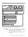
1
Service Manual
TLA721 Benchtop &
TLA7XM Expansion Mainframe
071-0912-00
This document applies to System Software version 4.1 and above.
Warning
The servicing instructions are for use by qualified
personnel only. To avoid personal injury, do not
perform any servicing unless you are qualified to
do so. Refer to all safety summaries prior to
performing service.
www.tektronix.com
Copyright © Tektronix, Inc. All rights reserved. Licensed software products are owned by Tektronix or its suppliers and
are protected by United States copyright laws and international treaty provisions.
Use, duplication, or disclosure by the Government is subject to restrictions as set forth in subparagraph (c)(1)(ii) of the
Rights in Technical Data and Computer Software clause at DFARS 252.227-7013, or subparagraphs (c)(1) and (2) of the
Commercial Computer Software - Restricted Rights clause at FAR 52.227-19, as applicable.
Tektronix products are covered by U.S. and foreign patents, issued and pending. Information in this publication supercedes
that in all previously published material. Specifications and price change privileges reserved.
Tektronix, Inc., P.O. Box 500, Beaverton, OR 97077
TEKTRONIX and TEK are registered trademarks of Tektronix, Inc.
WARRANTY
Tektronix warrants that the products that it manufactures and sells will be free from defects in materials and
workmanship for a period of one (1) year from the date of shipment. If a product proves defective during this
warranty period, Tektronix, at its option, either will repair the defective product without charge for parts and labor,
or will provide a replacement in exchange for the defective product.
In order to obtain service under this warranty, Customer must notify Tektronix of the defect before the expiration
of the warranty period and make suitable arrangements for the performance of service. Customer shall be
responsible for packaging and shipping the defective product to the service center designated by Tektronix, with
shipping charges prepaid. Tektronix shall pay for the return of the product to Customer if the shipment is to a
location within the country in which the Tektronix service center is located. Customer shall be responsible for
paying all shipping charges, duties, taxes, and any other charges for products returned to any other locations.
This warranty shall not apply to any defect, failure or damage caused by improper use or improper or inadequate
maintenance and care. Tektronix shall not be obligated to furnish service under this warranty a) to repair damage
resulting from attempts by personnel other than Tektronix representatives to install, repair or service the product;
b) to repair damage resulting from improper use or connection to incompatible equipment; c) to repair any
damage or malfunction caused by the use of non-Tektronix supplies; or d) to service a product that has been
modified or integrated with other products when the effect of such modification or integration increases the time
or difficulty of servicing the product.
THIS WARRANTY IS GIVEN BY TEKTRONIX IN LIEU OF ANY OTHER WARRANTIES, EXPRESS
OR IMPLIED. TEKTRONIX AND ITS VENDORS DISCLAIM ANY IMPLIED WARRANTIES OF
MERCHANTABILITY OR FITNESS FOR A PARTICULAR PURPOSE. TEKTRONIX’
RESPONSIBILITY TO REPAIR OR REPLACE DEFECTIVE PRODUCTS IS THE SOLE AND
EXCLUSIVE REMEDY PROVIDED TO THE CUSTOMER FOR BREACH OF THIS WARRANTY.
TEKTRONIX AND ITS VENDORS WILL NOT BE LIABLE FOR ANY INDIRECT, SPECIAL,
INCIDENTAL, OR CONSEQUENTIAL DAMAGES IRRESPECTIVE OF WHETHER TEKTRONIX OR
THE VENDOR HAS ADVANCE NOTICE OF THE POSSIBILITY OF SUCH DAMAGES.
Table of Contents
General Safety Summary . . . . . . . . . . . . . . . . . . . . . . . . . . . . . . . . . . .
Service Safety Summary . . . . . . . . . . . . . . . . . . . . . . . . . . . . . . . . . . . .
Preface . . . . . . . . . . . . . . . . . . . . . . . . . . . . . . . . . . . . . . . . . . . . . . . . . . .
ix
xii
xiii
Manual Structure . . . . . . . . . . . . . . . . . . . . . . . . . . . . . . . . . . . . . . . . . . . . . . . .
Manual Conventions . . . . . . . . . . . . . . . . . . . . . . . . . . . . . . . . . . . . . . . . . . . . . .
Related Manuals . . . . . . . . . . . . . . . . . . . . . . . . . . . . . . . . . . . . . . . . . . . . . . . . .
xiii
xiv
xiv
Introduction . . . . . . . . . . . . . . . . . . . . . . . . . . . . . . . . . . . . . . . . . . . . . .
xvii
Adjustment and Certification Interval . . . . . . . . . . . . . . . . . . . . . . . . . . . . . . . .
Service Strategy . . . . . . . . . . . . . . . . . . . . . . . . . . . . . . . . . . . . . . . . . . . . . . . . .
Service Offerings . . . . . . . . . . . . . . . . . . . . . . . . . . . . . . . . . . . . . . . . . . . . . . . .
Contacting Tektronix . . . . . . . . . . . . . . . . . . . . . . . . . . . . . . . . . . . . . . . . . . . . .
xvii
xvii
xviii
xix
Product Description . . . . . . . . . . . . . . . . . . . . . . . . . . . . . . . . . . . . . . . . . . . . . .
Characteristic Tables . . . . . . . . . . . . . . . . . . . . . . . . . . . . . . . . . . . . . . . . . . . . .
1-- 1
1-- 2
Installation . . . . . . . . . . . . . . . . . . . . . . . . . . . . . . . . . . . . . . . . . . . . . . . . . . . . .
Mainframe Controls and Connectors . . . . . . . . . . . . . . . . . . . . . . . . . . . . . . . . .
Benchtop Controller Controls and Connectors . . . . . . . . . . . . . . . . . . . . . . . . .
Expansion Module Controls and Connectors . . . . . . . . . . . . . . . . . . . . . . . . . . .
Operating System and Application Interface . . . . . . . . . . . . . . . . . . . . . . . . . .
2-- 1
2-- 3
2-- 16
2-- 22
2-- 23
Benchtop Controller . . . . . . . . . . . . . . . . . . . . . . . . . . . . . . . . . . . . . . . . . . . . . .
Mainframe . . . . . . . . . . . . . . . . . . . . . . . . . . . . . . . . . . . . . . . . . . . . . . . . . . . . .
Expansion Module . . . . . . . . . . . . . . . . . . . . . . . . . . . . . . . . . . . . . . . . . . . . . . .
3-- 1
3-- 4
3-- 7
Specifications
Operating Infromation
Theory of Operation
Performance Verification
Summary Verification . . . . . . . . . . . . . . . . . . . . . . . . . . . . . . . . . . . . . . . . . . . . .
Test Equipment . . . . . . . . . . . . . . . . . . . . . . . . . . . . . . . . . . . . . . . . . . . . . . . . . .
Functional Verification . . . . . . . . . . . . . . . . . . . . . . . . . . . . . . . . . . . . . . . . . . . .
Certification . . . . . . . . . . . . . . . . . . . . . . . . . . . . . . . . . . . . . . . . . . . . . . . . . . . .
Performance Verification Procedures . . . . . . . . . . . . . . . . . . . . . . . . . . . . . . . . .
4-- 1
4-- 1
4-- 3
4-- 5
4-- 6
Calibration Data Report . . . . . . . . . . . . . . . . . . . . . . . . . . . . . . . . . . . .
4--9
Adjustment Procedures
Maintenance
Preparation . . . . . . . . . . . . . . . . . . . . . . . . . . . . . . . . . . . . . . . . . . . . . . . . . . . . .
Preventing ESD . . . . . . . . . . . . . . . . . . . . . . . . . . . . . . . . . . . . . . . . . . . . . . . . .
Inspection and Cleaning . . . . . . . . . . . . . . . . . . . . . . . . . . . . . . . . . . . . . . . . . . .
TLA721 Benchtop & TLA7XM Expansion Mainframe Service Manual
6-- 1
6-- 1
6-- 2
i
Table of Contents
Mainframe Removal and Installation Procedures . . . . . . . . . . . . . . .
6--5
Equipment Required . . . . . . . . . . . . . . . . . . . . . . . . . . . . . . . . . . . . . . . . . . . . . .
Install Empty Slot Panel Fillers . . . . . . . . . . . . . . . . . . . . . . . . . . . . . . . . . . . . .
Blower Assembly . . . . . . . . . . . . . . . . . . . . . . . . . . . . . . . . . . . . . . . . . . . . . . . .
Removing the Enhanced Monitor Board . . . . . . . . . . . . . . . . . . . . . . . . . . . . . .
Power Supply . . . . . . . . . . . . . . . . . . . . . . . . . . . . . . . . . . . . . . . . . . . . . . . . . . .
Mainframe Cover . . . . . . . . . . . . . . . . . . . . . . . . . . . . . . . . . . . . . . . . . . . . . . . .
Card Guides . . . . . . . . . . . . . . . . . . . . . . . . . . . . . . . . . . . . . . . . . . . . . . . . . . . .
Nut Rails . . . . . . . . . . . . . . . . . . . . . . . . . . . . . . . . . . . . . . . . . . . . . . . . . . . . . . .
Temperature Sense Board . . . . . . . . . . . . . . . . . . . . . . . . . . . . . . . . . . . . . . . . . .
EMI DIN Shields . . . . . . . . . . . . . . . . . . . . . . . . . . . . . . . . . . . . . . . . . . . . . . . .
Backplane . . . . . . . . . . . . . . . . . . . . . . . . . . . . . . . . . . . . . . . . . . . . . . . . . . . . . .
Special Configuration Options . . . . . . . . . . . . . . . . . . . . . . . . . . . . . . . . . . . . . .
6-- 5
6-- 6
6-- 7
6-- 10
6-- 12
6-- 13
6-- 14
6-- 16
6-- 17
6-- 19
6-- 20
6-- 23
Benchtop Controller Removal and Installation Procedures . . . . . . .
6--25
Equipment Required . . . . . . . . . . . . . . . . . . . . . . . . . . . . . . . . . . . . . . . . . . . . . .
Replaceable Hard Disk Drive . . . . . . . . . . . . . . . . . . . . . . . . . . . . . . . . . . . . . . .
Injector/Ejector Handles . . . . . . . . . . . . . . . . . . . . . . . . . . . . . . . . . . . . . . . . . . .
Covers . . . . . . . . . . . . . . . . . . . . . . . . . . . . . . . . . . . . . . . . . . . . . . . . . . . . . . . . .
Front Panel and Hard Disk Drive Interface Board . . . . . . . . . . . . . . . . . . . . . . .
Fixed Hard Drive . . . . . . . . . . . . . . . . . . . . . . . . . . . . . . . . . . . . . . . . . . . . . . . .
CD-ROM Drive . . . . . . . . . . . . . . . . . . . . . . . . . . . . . . . . . . . . . . . . . . . . . . . . .
Button Battery . . . . . . . . . . . . . . . . . . . . . . . . . . . . . . . . . . . . . . . . . . . . . . . . . .
Main Memory . . . . . . . . . . . . . . . . . . . . . . . . . . . . . . . . . . . . . . . . . . . . . . . . . . .
Floppy Disk Drive . . . . . . . . . . . . . . . . . . . . . . . . . . . . . . . . . . . . . . . . . . . . . . .
6-- 25
6-- 26
6-- 28
6-- 29
6-- 30
6-- 34
6-- 36
6-- 37
6-- 38
6-- 39
Expansion Module Removal and Installation Procedures . . . . . . . . .
6--45
Equipment Required . . . . . . . . . . . . . . . . . . . . . . . . . . . . . . . . . . . . . . . . . . . . . .
Ejector Handles . . . . . . . . . . . . . . . . . . . . . . . . . . . . . . . . . . . . . . . . . . . . . . . . .
Expansion Module Cover . . . . . . . . . . . . . . . . . . . . . . . . . . . . . . . . . . . . . . . . . .
Expansion Module Circuit Board . . . . . . . . . . . . . . . . . . . . . . . . . . . . . . . . . . . .
Soldered-On Components . . . . . . . . . . . . . . . . . . . . . . . . . . . . . . . . . . . . . . . . . .
6-- 45
6-- 46
6-- 47
6-- 48
6-- 49
Troubleshooting . . . . . . . . . . . . . . . . . . . . . . . . . . . . . . . . . . . . . . . . . . .
6--51
Service Level . . . . . . . . . . . . . . . . . . . . . . . . . . . . . . . . . . . . . . . . . . . . . . . . . . .
Check for Common Problems . . . . . . . . . . . . . . . . . . . . . . . . . . . . . . . . . . . . . .
Isolating System Problems . . . . . . . . . . . . . . . . . . . . . . . . . . . . . . . . . . . . . . . . .
Eliminate other Problem Sources . . . . . . . . . . . . . . . . . . . . . . . . . . . . . . . . . . . .
Diagnostics . . . . . . . . . . . . . . . . . . . . . . . . . . . . . . . . . . . . . . . . . . . . . . . . . . . . .
BIOS Error Messages . . . . . . . . . . . . . . . . . . . . . . . . . . . . . . . . . . . . . . . . . . . . .
TLA Startup Sequence . . . . . . . . . . . . . . . . . . . . . . . . . . . . . . . . . . . . . . . . . . . .
Troubleshoot the Benchtop Controller . . . . . . . . . . . . . . . . . . . . . . . . . . . . . . . .
Troubleshoot the Mainframe . . . . . . . . . . . . . . . . . . . . . . . . . . . . . . . . . . . . . . .
Troubleshoot the Expansion Mainframe . . . . . . . . . . . . . . . . . . . . . . . . . . . . . .
Adjustments after Repair . . . . . . . . . . . . . . . . . . . . . . . . . . . . . . . . . . . . . . . . . .
6-- 52
6-- 52
6-- 56
6-- 59
6-- 59
6-- 62
6-- 65
6-- 66
6-- 68
6-- 71
6-- 72
Repackaging Instructions . . . . . . . . . . . . . . . . . . . . . . . . . . . . . . . . . . .
6--73
Packaging . . . . . . . . . . . . . . . . . . . . . . . . . . . . . . . . . . . . . . . . . . . . . . . . . . . . . .
Shipping to the Service Center . . . . . . . . . . . . . . . . . . . . . . . . . . . . . . . . . . . . . .
6-- 73
6-- 73
Service Options . . . . . . . . . . . . . . . . . . . . . . . . . . . . . . . . . . . . . . . . . . . . . . . . . .
Product Options . . . . . . . . . . . . . . . . . . . . . . . . . . . . . . . . . . . . . . . . . . . . . . . . .
Power Cord Options . . . . . . . . . . . . . . . . . . . . . . . . . . . . . . . . . . . . . . . . . . . . . .
7-- 1
7-- 2
7-- 2
Options
ii
TLA721 Benchtop & TLA7XM Expansion Mainframe Service Manual
Table of Contents
Electrical Parts List
Diagrams
Mechanical Parts List
Parts Ordering Information . . . . . . . . . . . . . . . . . . . . . . . . . . . . . . . . . . . . . . . . .
Using the Replaceable Parts List . . . . . . . . . . . . . . . . . . . . . . . . . . . . . . . . . . . .
TLA721 Benchtop & TLA7XM Expansion Mainframe Service Manual
10-- 1
10-- 2
iii
Table of Contents
List of Figures
Figure 1--1: Dimensions of the benchtop and expansion mainframe
Figure 1--2: Dimensions of the benchtop and expansion mainframe
with rackmount option . . . . . . . . . . . . . . . . . . . . . . . . . . . . . . . . . .
Figure 2--1: Power cord identification chart . . . . . . . . . . . . . . . . . . . .
Figure 2--2: Front view of the benchtop chassis with a benchtop
controller . . . . . . . . . . . . . . . . . . . . . . . . . . . . . . . . . . . . . . . . . . . . .
Figure 2--3: Rear view of the benchtop chassis . . . . . . . . . . . . . . . . . .
Figure 2--4: Passive monitor connector . . . . . . . . . . . . . . . . . . . . . . . .
Figure 2--5: Rear view of the enhanced monitor . . . . . . . . . . . . . . . . .
Figure 2--6: Enhanced monitor board jumpers . . . . . . . . . . . . . . . . .
Figure 2--7: Enhanced monitor board flash jumper . . . . . . . . . . . . .
Figure 2--8: Enhanced Monitor RS-232 connector . . . . . . . . . . . . . . .
Figure 2--9: Front view of the benchtop controller . . . . . . . . . . . . . . .
Figure 2--10: Front view of the benchtop controller . . . . . . . . . . . . . .
Figure 3--1: Interconnection and block diagram for the benchtop
mainframe and controller . . . . . . . . . . . . . . . . . . . . . . . . . . . . . . . .
Figure 3--2: Mainframe block diagram . . . . . . . . . . . . . . . . . . . . . . . .
Figure 3--3: Benchtop and expansion mainframe block diagram . . .
Figure 4--1: Calibration/certification procedure flow chart . . . . . . .
Figure 4--2: Benchtop and expansion mainframe 25-pin rear panel
connector . . . . . . . . . . . . . . . . . . . . . . . . . . . . . . . . . . . . . . . . . . . . .
Figure 6--1: Installing the empty slot panel fillers . . . . . . . . . . . . . . .
Figure 6--2: Location of blower assembly screws . . . . . . . . . . . . . . . .
Figure 6--3: Removing the blower assembly . . . . . . . . . . . . . . . . . . . .
Figure 6--4: Removing the blower . . . . . . . . . . . . . . . . . . . . . . . . . . . .
Figure 6--5: Removing the enhanced monitor board . . . . . . . . . . . . .
Figure 6--6: Removing the power supply . . . . . . . . . . . . . . . . . . . . . . .
Figure 6--7: Removing the mainframe cover . . . . . . . . . . . . . . . . . . . .
Figure 6--8: Removing the top and bottom card guides . . . . . . . . . . .
Figure 6--9: Replacing the top and bottom nut rails . . . . . . . . . . . . .
Figure 6--10: Removing the temperature sense board . . . . . . . . . . . .
Figure 6--11: Removing the backplane EMI DIN shields . . . . . . . . . .
Figure 6--12: Removing the backplane . . . . . . . . . . . . . . . . . . . . . . . .
Figure 6--13: Soft power down jumper setting . . . . . . . . . . . . . . . . . .
Figure 6--14: Power switch connectors . . . . . . . . . . . . . . . . . . . . . . . . .
Figure 6--15: Removing the replaceable hard disk drive . . . . . . . . . .
iv
1--15
1--16
2--2
2--3
2--4
2--5
2--8
2--9
2--10
2--11
2--16
2--22
3--2
3--5
3--8
4--2
4--7
6--6
6--8
6--9
6--9
6--10
6--12
6--13
6--15
6--16
6--18
6--19
6--21
6--22
6--24
6--26
TLA721 Benchtop & TLA7XM Expansion Mainframe Service Manual
Table of Contents
Figure 6--16: Removing the hard disk drive from the cartridge . . . .
Figure 6--17: Removal and installation of the ejectors . . . . . . . . . . . .
Figure 6--18: Removing and installing the left and rear covers . . . .
Figure 6--19: Removing and installing the front panel hardware . . .
Figure 6--20: Removing screws from the front and sides of the
controller . . . . . . . . . . . . . . . . . . . . . . . . . . . . . . . . . . . . . . . . . . . . .
Figure 6--21: Removing and installing the fixed hard disk drive and
CD-ROM drive . . . . . . . . . . . . . . . . . . . . . . . . . . . . . . . . . . . . . . . .
Figure 6--22: Removal and installation of the button battery and
memory . . . . . . . . . . . . . . . . . . . . . . . . . . . . . . . . . . . . . . . . . . . . . . .
Figure 6--23: Removing the processor and interface boards . . . . . . .
Figure 6--24: Separating the processor and interface boards . . . . . .
Figure 6--25: Removing the floppy disk drive from the interface
board . . . . . . . . . . . . . . . . . . . . . . . . . . . . . . . . . . . . . . . . . . . . . . . . .
Figure 6--26: Removal and installation of the ejector handles . . . . .
Figure 6--27: Removal and installation of the cover . . . . . . . . . . . . . .
Figure 6--28: Removing the circuit board . . . . . . . . . . . . . . . . . . . . .
Figure 6--29: ResMan32 program output . . . . . . . . . . . . . . . . . . . . . .
Figure 6--30: Startup sequence . . . . . . . . . . . . . . . . . . . . . . . . . . . . . . .
Figure 6--31: Benchtop controller troubleshooting tree . . . . . . . . . . .
Figure 6--32: Mainframe troubleshooting tree . . . . . . . . . . . . . . . . . .
Figure 9--1: Interconnection diagram . . . . . . . . . . . . . . . . . . . . . . . . .
Figure 9--2: Benchtop mainframe block diagram . . . . . . . . . . . . . . .
Figure 9--3: Benchtop and expansion mainframe block diagram . .
Figure 10--1: Cabinet and chassis assembly . . . . . . . . . . . . . . . . . . . .
Figure 10--2: Circuit boards and chassis parts . . . . . . . . . . . . . . . . . .
Figure 10--3: Power supply, monitor, and fan assembly . . . . . . . . . .
Figure 10--4: Benchtop controller exploded view (covers and
handles) . . . . . . . . . . . . . . . . . . . . . . . . . . . . . . . . . . . . . . . . . . . . . .
Figure 10--5: Benchtop controller exploded view (internal parts) . .
Figure 10--6: Expansion module exploded view . . . . . . . . . . . . . . . . .
Figure 10--7: Expansion module exploded view . . . . . . . . . . . . . . . . .
Figure 10--8: IView cables . . . . . . . . . . . . . . . . . . . . . . . . . . . . . . . . . . .
TLA721 Benchtop & TLA7XM Expansion Mainframe Service Manual
6--27
6--28
6--29
6--31
6--32
6--35
6--37
6--40
6--41
6--42
6--46
6--47
6--48
6--58
6--66
6--68
6--70
9--1
9--2
9--3
10--7
10--9
10--11
10--13
10--15
10--17
10--19
10--19
v
Table of Contents
List of Tables
Table i: Tektronix Logic Analyzer Family Documentation . . . . . . .
Table 1--1: Benchtop controller characteristics . . . . . . . . . . . . . . . . .
Table 1--2: Front panel characteristics . . . . . . . . . . . . . . . . . . . . . . . .
Table 1--3: Backplane interface . . . . . . . . . . . . . . . . . . . . . . . . . . . . . .
Table 1--4: External signal interface . . . . . . . . . . . . . . . . . . . . . . . . . .
Table 1--5: Backplane latencies . . . . . . . . . . . . . . . . . . . . . . . . . . . . . .
Table 1--6: Benchtop and expansion mainframe AC power source .
Table 1--7: Benchtop and expansion mainframe secondary power . .
Table 1--8: Benchtop and expansion mainframe cooling . . . . . . . . .
Table 1--9: Atmospheric characteristics . . . . . . . . . . . . . . . . . . . . . . .
Table 1--10: Mechanical characteristics . . . . . . . . . . . . . . . . . . . . . . .
Table 1--11: Certifications and compliances . . . . . . . . . . . . . . . . . . . .
Table 2--1: Passive monitor connector pinouts . . . . . . . . . . . . . . . . . .
Table 2--2: RS-232 pin connector . . . . . . . . . . . . . . . . . . . . . . . . . . . . .
Table 2--3: P1 connector pinouts . . . . . . . . . . . . . . . . . . . . . . . . . . . .
Table 2--4: P2 connector pinouts for slots 1 -- 12 . . . . . . . . . . . . . . . .
Table 2--5: P2 connector pinouts for slot 0 . . . . . . . . . . . . . . . . . . . . .
Table 2--6: Mouse port pin assignments . . . . . . . . . . . . . . . . . . . . . . .
Table 2--7: Keyboard port pin assignments . . . . . . . . . . . . . . . . . . . .
Table 2--8: PC CardBus32 port pin assignments . . . . . . . . . . . . . . . .
Table 2--9: USB pin assignments . . . . . . . . . . . . . . . . . . . . . . . . . . . . .
Table 2--10: SVGA OUT pin assignments . . . . . . . . . . . . . . . . . . . . .
Table 2--11: RS-232 Port pin assignments . . . . . . . . . . . . . . . . . . . . .
Table 2--12: LPT port pin assignments . . . . . . . . . . . . . . . . . . . . . . . .
Table 4--1: Test equipment . . . . . . . . . . . . . . . . . . . . . . . . . . . . . . . . . .
Table 4--2: Functional verification procedures . . . . . . . . . . . . . . . . .
Table 4--3: Performance verification procedures . . . . . . . . . . . . . . . .
Table 4--4: Power supply voltages at the 25-pin connector . . . . . . . .
Table 6--1: External inspection check list . . . . . . . . . . . . . . . . . . . . . .
Table 6--2: Internal inspection check list . . . . . . . . . . . . . . . . . . . . . .
Table 6--3: Equipment required to service the mainframes . . . . . . .
Table 6--4: Enhanced monitor board jumpers . . . . . . . . . . . . . . . . . .
Table 6--5: Mainframe backplane jumpers . . . . . . . . . . . . . . . . . . . . .
Table 6--6: Equipment required to service the benchtop controller .
Table 6--7: Signal wire identification . . . . . . . . . . . . . . . . . . . . . . . . .
vi
xv
1--3
1--5
1--6
1--7
1--9
1--11
1--11
1--12
1--13
1--14
1--16
2--6
2--11
2--13
2--14
2--15
2--17
2--17
2--19
2--19
2--20
2--20
2--21
4--3
4--3
4--6
4--7
6--3
6--4
6--5
6--11
6--22
6--25
6--43
TLA721 Benchtop & TLA7XM Expansion Mainframe Service Manual
Table of Contents
Table 6--8: Equipment required to service the expansion module . .
Table 6--9: Failure symptoms and possible causes . . . . . . . . . . . . . . .
Table 6--10: Command line options for ResMan32 . . . . . . . . . . . . . .
Table 6--11: Power-on diagnostic tests . . . . . . . . . . . . . . . . . . . . . . . . .
Table 6--12: BIOS error codes and explanations . . . . . . . . . . . . . . . .
Table 7--1: TLA721 Service Options . . . . . . . . . . . . . . . . . . . . . . . . . .
Table 7--2: TLA7XM Service Options . . . . . . . . . . . . . . . . . . . . . . . . .
TLA721 Benchtop & TLA7XM Expansion Mainframe Service Manual
6--45
6--53
6--57
6--60
6--62
7--1
7--1
vii
Table of Contents
viii
TLA721 Benchtop & TLA7XM Expansion Mainframe Service Manual
General Safety Summary
Review the following safety precautions to avoid injury and prevent damage to
this product or any products connected to it. To avoid potential hazards, use this
product only as specified.
Only qualified personnel should perform service procedures.
While using this product, you may need to access other parts of the system. Read
the General Safety Summary in other system manuals for warnings and cautions
related to operating the system.
To Avoid Fire or
Personal Injury
Use Proper Power Cord. Use only the power cord specified for this product and
certified for the country of use.
Connect and Disconnect Properly. Do not connect or disconnect probes or test
leads while they are connected to a voltage source.
Ground the Product. This product is grounded through the grounding conductor
of the power cord. To avoid electric shock, the grounding conductor must be
connected to earth ground. Before making connections to the input or output
terminals of the product, ensure that the product is properly grounded.
Observe All Terminal Ratings. To avoid fire or shock hazard, observe all ratings
and markings on the product. Consult the product manual for further ratings
information before making connections to the product.
Do not apply a potential to any terminal, including the common terminal, that
exceeds the maximum rating of that terminal.
Do Not Operate Without Covers. Do not operate this product with covers or panels
removed.
Use Proper Fuse. Use only the fuse type and rating specified for this product.
Avoid Exposed Circuitry. Do not touch exposed connections and components
when power is present.
Do Not Operate With Suspected Failures. If you suspect there is damage to this
product, have it inspected by qualified service personnel.
Do Not Operate in Wet/Damp Conditions.
Do Not Operate in an Explosive Atmosphere.
Keep Product Surfaces Clean and Dry.
Provide Proper Ventilation. Refer to the manual’s installation instructions for
details on installing the product so it has proper ventilation.
TLA721 Benchtop & TLA7XM Expansion Mainframe Service Manual
ix
General Safety Summary
Symbols and Terms
Terms in this Manual. These terms may appear in this manual:
WARNING. Warning statements identify conditions or practices that could result
in injury or loss of life.
CAUTION. Caution statements identify conditions or practices that could result in
damage to this product or other property.
Terms on the Product. These terms may appear on the product:
DANGER indicates an injury hazard immediately accessible as you read the
marking.
WARNING indicates an injury hazard not immediately accessible as you read the
marking.
CAUTION indicates a hazard to property including the product.
Symbols on the Product. The following symbols may appear on the product:
CAUTION
Refer to Manual
x
WARNING
High Voltage
Protective Ground
(Earth) Terminal
TLA721 Benchtop & TLA7XM Expansion Mainframe Service Manual
Service Safety Summary
Only qualified personnel should perform service procedures. Read this Service
Safety Summary and the General Safety Summary before performing any service
procedures.
Do Not Service Alone. Do not perform internal service or adjustments of this
product unless another person capable of rendering first aid and resuscitation is
present.
Disconnect Power. To avoid electric shock, switch off the instrument power, then
disconnect the power cord from the mains power.
Use Care When Servicing With Power On. Dangerous voltages or currents may
exist in this product. Disconnect power, remove battery (if applicable), and
disconnect test leads before removing protective panels, soldering, or replacing
components.
To avoid electric shock, do not touch exposed connections.
TLA721 Benchtop & TLA7XM Expansion Mainframe Service Manual
xi
Service Safety Summary
xii
TLA721 Benchtop & TLA7XM Expansion Mainframe Service Manual
Preface
This is the service manual for the TLA721 Benchtop Mainframe and the
TLA7XM Expansion Mainframe. Read this preface to learn how this manual is
structured, what conventions it uses, and where you can find other information
related to servicing this product. Read the Introduction following this preface for
safety and other important background information needed before using this
manual for servicing this product.
Manual Structure
This manual is divided into chapters, which are made up of related subordinate
topics. These topics can be cross referenced as sections.
Be sure to read the introductions to all procedures. These introductions provide
important information needed to do the service correctly, safely, and efficiently.
A brief description of each chapter follows:
H
Specifications contains a product description of the instrument and tables of
the characteristics and descriptions that apply to it.
H
Operating information includes basic controls and connectors on the
instrument. It also provides a high-level overview of the operating system
and application interface. Refer to the Tektronix Logic Analyzer Family User
Manual for detailed information on the operating system and for installation
information not found in this document.
H
Theory of Operation contains a high-level overview of the basic operation of
the instrument to help you service the instrument to a module level.
H
Performance Verification contains the performance verification and
certification procedures for the instrument.
H
Adjustments notes that there are no adjustments for the instrument. For
adjustment information on the product modules, refer to the appropriate
service module manual.
H
Maintenance contains information and procedures for doing preventative and
corrective maintenance on the instrument. Included are instructions for
cleaning, for removal and installation of replaceable parts, and for troubleshooting product failures. Instructions for shipping the instrument are
included in this chapter.
H
Options contains information on factory installed options and accessories
that may be purchased for your instrument.
TLA721 Benchtop & TLA7XM Expansion Mainframe Service Manual
xiii
Preface
H
Diagrams contains block diagrams of the instrument and interconnection
diagrams useful for isolating failures in the instrument.
H
Mechanical Parts List includes tables of all replaceable parts for the
instrument along with the Tektronix part number.
Manual Conventions
This manual uses certain conventions that you should become familiar with
before attempting service.
Mainframes
This manual covers at least two different kinds of mainframes. The benchtop
mainframe consists of a mainframe with a benchtop controller module. Other
slots are available for installing logic analyzer (LA) modules, digitizing
oscilloscope (DSO) modules, or pattern generator (Patgen) modules. The
expansion mainframe consists of a mainframe with an expansion controller
module. Expansion mainframes are used to expand the capabilities of a single
TLA700 Logic Analyzer.
Modules
Throughout this manual, the term module refers to a TLA700 Series Logic
Analyzer, DSO unit, or pattern generator unit that mounts inside the mainframe.
A module is composed of circuit cards, interconnecting cables, and a user-accessible front panel enclosed in a mechanical frame.
Replaceable Parts
This manual refers to any field-replaceable assembly or mechanical part
specifically by its name or generically as a replaceable part. In general, a
replaceable part is any circuit board or assembly, such as the hard disk drive, or a
mechanical part, such as the I/O port connectors, that is listed in the replaceable
parts list.
Safety
Symbols and terms related to safety appear in the Service Safety Summary found
at the beginning of this manual.
Related Manuals
The following manuals are available as part of the Tektronix Logic Analyzer
Family documentation set. The procedures in this manual assume that the service
personnel have access to all manuals listed in the following table. Other manuals
may exist outside of the table as the product line offerings change. Contact your
local Tektronix Service Representative for the latest part numbers of the service
documentation. You can also obtain part numbers from the online help for the
instrument.
xiv
TLA721 Benchtop & TLA7XM Expansion Mainframe Service Manual
Preface
Table i: Tektronix Logic Analyzer Family Documentation
Manual name
Description
Service use
The Tektronix Logic Analyzer Family User
Manual
Provides basic operation and installation
Installation and removal of LA, DSO, and
information for the Tektronix Logic Analyzer pattern generator modules as well as the
Family.
mainframes.
Reinstallation of the system and application
software.
The TLA715 Portable Mainframe Service
Manual.
Provides service information for the
TLA715 Portable Mainframe.
Isolating and correcting failures in the
portable mainframe and expansion
mainframes.
The TLA7Nx/TLA7Px/TLA7Qx Logic
Analyzer Module Service Manual.
Provides service information for the logic
analyzer modules.
Isolating and correcting failures in the logic
analyzer module.
Performing periodic or after-repair functional or performance verifications, calibrations,
and certifications for the logic analyzer
modules.
Performing periodic or after-repair adjustments for the logic analyzer modules.
The TLA7Dx/TLA7EX Digitizing Oscilloscope Module Service Manual.
Provides service information for the DSO
modules.
Isolating and correcting failures in the DSO
module.
Performing periodic or after-repair functional or performance verifications, calibrations,
and certifications for the DSO modules.
Performing periodic or after-repair adjustments for the DSO modules.
The TLA7PG2 Pattern Generator Module
Service Manual.
Provides service information for the pattern
generator modules.
Isolating and correcting failures in the
pattern generator module.
Performing periodic or after-repair functional or performance verifications, calibrations,
and certifications for the pattern generator
modules.
TLA721 Benchtop & TLA7XM Expansion Mainframe Service Manual
xv
Preface
xvi
TLA721 Benchtop & TLA7XM Expansion Mainframe Service Manual
Introduction
This manual contains information needed to properly service the portable
mainframe. This introduction contains information critical to safe and effective
servicing.
To prevent personal injury or damage to the instrument, consider the following
requirements before attempting service:
H
Read the General Safety Summary and Service Safety Summary found at the
beginning of this manual.
H
Read the Operating Basics chapter for information on the controls,
connectors, and operating system. This information is useful before servicing
the instrument.
H
The procedures in this manual may only be performed by a qualified service
person.
Be sure to follow all warnings, cautions and notes.
Adjustment and Certification Interval
Generally, you should perform the adjustments and certification (calibration)
once per year, or following repairs that may affect adjustment or calibration.
Service Strategy
This manual supports and contains information needed for periodic maintenance
of the mainframe. It supports and contains information for corrective maintenance of this product:
H
supports isolation of faults to the failed circuit board or assembly level
shown in the Replaceable Parts List
H
supports removal and replacement of boards or assemblies
H
supports removal and replacement of the fuse, knobs, chassis, and other
mechanical parts listed in the parts lists
This manual does not support component-level fault isolation and replacement.
TLA721 Benchtop & TLA7XM Expansion Mainframe Service Manual
xvii
Introduction
Service Offerings
Tektronix provides service to cover repair under warranty as well as other
services that are designed to meet your specific service needs.
Whether providing warranty repair service or any of the other services listed
below, Tektronix service technicians are equipped to service the instrument.
Services are provided at Tektronix Services Centers and on-site at your facility,
depending on your location.
Warranty Repair Service
Calibration and Repair
Service
Tektronix warrants this product for one year from date of purchase. The warranty
is located behind the title page in this manual. Tektronix technicians provide
warranty service at most Tektronix service locations worldwide. The Tektronix
product catalog lists all service locations worldwide.
In addition to warranty repair, Tektronix Service offers calibration and other
services which provide solutions to your service needs and quality standards
compliance requirements.
The following services can be tailored to fit your requirements for calibration
and/or repair of your portable mainframe.
Service Options. Tektronix Service Options can be selected at the time you
purchase your instrument. You select these options to provide the services that
best meet your service needs.
Service Agreements. If service options are not added to the instrument purchase,
then service agreements are available on an annual basis to provide calibration
services or post-warranty repair coverage. Service agreements may be customized to meet special turn-around time and/or on-site requirements.
Service on Demand. Tektronix offers calibration and repair services on a
“per-incident” basis that is available with standard prices.
Self Service. Tektronix supports repair to the replaceable-part level by providing
for circuit board exchange.
Use this service to reduce down-time for repair by exchanging circuit boards for
remanufactured ones. Tektronix ships updated and tested exchange boards. Each
board comes with a 90-day service warranty.
For More Information. Contact your local Tektronix service center or sales
engineer for more information on any of the Calibration and Repair Services just
described.
xviii
TLA721 Benchtop & TLA7XM Expansion Mainframe Service Manual
Introduction
Contacting Tektronix
Phone
1-800-833-9200*
Address
Tektronix, Inc.
Department or name (if known)
14200 SW Karl Braun Drive
P.O. Box 500
Beaverton, OR 97077
USA
Web site
www.tektronix.com
Sales support
1-800-833-9200, select option 1*
Service support
1-800-833-9200, select option 2*
Technical support
Email: [email protected]
1-800-833-9200, select option 3*
1-503-627-2400
6:00 a.m. - 5:00 p.m. Pacific time
*
This phone number is toll free in North America. After office hours, please leave a
voice mail message.
Outside North America, contact a Tektronix sales office or distributor; see the
Tektronix web site for a list of offices.
TLA721 Benchtop & TLA7XM Expansion Mainframe Service Manual
xix
Introduction
xx
TLA721 Benchtop & TLA7XM Expansion Mainframe Service Manual
Specifications
This chapter provides a brief product description and lists the warranted
characteristics, nominal traits, and typical characteristics of the TLA721
Benchtop Mainframe and the TLA7XM Expansion Mainframe.
Product Description
Both the benchtop mainframe and the expansion mainframes are basically
identical with the exception of the controllers. The benchtop mainframe includes
a PC controller that controls the entire instrument. The expansion mainframe
includes an expansion module that expands the capabilities of a benchtop
mainframe or a TLA715 Portable Mainframe. Each mainframe can function as a
logic analyzer, a digital storage oscilloscope, or a pattern generator, depending
on the module cards installed in its slots.
Benchtop Mainframe
The benchtop mainframe comprises of a benchtop chassis and the benchtop
controller. The benchtop controller is a Pentium III based, three-wide, C-size,
embedded Slot-0 Controller that incorporates the same controller as the TLA715
Portable Mainframe. The benchtop chassis is based on the high power, 13-slot,
VX1420A Mainframe without a readout and with additional labels.
The benchtop mainframe has the following key features:
H
Microsoft Windows operating system
H
Ten slots (excluding three slots for the benchtop controller) for compatibility
with new and existing LA, DSO, and patgen modules
H
Personal computer (PC) based processor architecture that provides a cost
effective, high-performance, system controller with automatic “PC connectivity” to a multitude off-the-shelf devices (such as Ethernet, modem,
printers) via standard PC I/O ports and two PC card (CardBus) slots
H
High-performance PC-based display system capable of driving large,
high-resolution, external monitors in multiple user selected formats via an
external SVGA port
H
Easy configuration of modules between slots and mainframes through the
automatic system configuration support of the resource manager and
application software
H
Precision clock, trigger line, and event signaling between the mainframe and
modules for real-time triggering, sequencing, and correlation of events
TLA721 Benchtop & TLA7XM Expansion Mainframe Service Manual
1- 1
Specifications
Expansion Mainframe
H
Easy access to field replaceable units (FRUs) to provide a low mean-time-torepair (MTTR) for exchange modules
H
Fan airflow capacity to support a reduction in audible noise levels
H
Mainframe compatible with international power standards, certified to
international safety and EMC requirements, and tested to rugged environmental standards
H
100% hardware and software compatibility with the TLA715 Portable
Mainframe, allowing you to transport modules, data, and end-user application programs between mainframes
The expansion mainframe comprises of a benchtop chassis and the expansion
module. The expansion module is a single-wide, C-size, modules that provides
cable connections to a benchtop mainframe or to a portable mainframe.
The expansion mainframe has the following key features:
H
Microsoft Windows operating system
H
12 slots (excluding one slot for the expansion module) for compatibility with
new and existing LA, DSO, and patgen modules
H
Precision clock, trigger line, and event signaling between the mainframe and
modules for real-time triggering, sequencing, and correlation of events
H
Easy access to field replaceable units (FRUs) to provide a low mean-time-torepair (MTTR) for exchange modules
H
Fan airflow capacity to support a reduction in audible noise levels
H
Mainframe compatible with international power standards, certified to
international safety and EMC requirements, and tested to rugged environmental standards
Characteristic Tables
This section contains the specifications for the portable mainframe. All
specifications are warranted unless noted “typical”. Typical characteristics
describe typical or average performance and provide useful reference information. Specifications marked with the n symbol are checked in the Performance
Verification chapter in this manual.
The specifications listed in this section are valid under the following conditions:
H
1- 2
The instrument must reside in an environment with temperature, altitude,
and humidity, within the operating limits described in Table 1--9 beginning
on page 1--13.
TLA721 Benchtop & TLA7XM Expansion Mainframe Service Manual
Specifications
H
The instrument has has a warm-up period of at least 20 minutes.
Tables 1--1 through 1--2 list the specifications for the TLA721 Benchtop
Controller.
Table 1- 1: Benchtop controller characteristics
Characteristic
Description
Operating system
Microsoft Windows 2000
Microprocessor
Intel 733 MHz Pentium III configuration with an Intel 815E chip-set
Main memory
Two 144 pin SODIMM sockets support one or two SDRAM modules
Available configurations
16, 32, 64, 256 MB per SODIMM
Installed configuration
512 MB maximum configuration
Speed
133 MHz
CAS latency
2, 3
RAS to CAS delay
2, 3
RAS precharge
2, 3
DRAM cycle time
5/7 or 7/9
Cache memory
512 KB, level 2 (L2) write-back cache
Flash BIOS
512 KB
Provides PC plug-and-play services with and without
Microsoft Windows operating system.
Flash based BIOS field upgradable via a floppy disk
Forced recovery jumper is provided
Real-time clock and CMOS setups NVRAM
Real-time clock/calendar. Standard and advanced PC CMOS setups: see BIOS
specifications
RTC, CMOS setup, & PnP NVRAM retention
time (Typical)
Battery life is typically > 7 years
Floppy disk drive
Standard 3.5 inch, 1.44 MB, high-density, double-sided, PC-compatible high-density
floppy disk drive
Transfer rate
500 Kbits per second
Access time (ave.)
194 ms
Bootable replaceable hard disk drive
Size
Standard PC compatible IDE (Integrated device Electronics) hard disk drive residing
on an EIDE interface
Maximum
30 GByte
Continually subject to change due to the fast-moving PC component environment
These storage capacities valid at product introduction
Interface
ATA-5/Enhanced IDE (EIDE)
TLA721 Benchtop & TLA7XM Expansion Mainframe Service Manual
1- 3
Specifications
Table 1- 1: Benchtop controller characteristics (Cont.)
Characteristic
Description
Average seek time
Read 12 ms
I/O data-transfer rate
33.3 MB/s maximum (U-DMA mode 2)
Average latency
7/14 ms
Cache buffer
512 KB
CD ROM drive
Standard PC compatible IDE (Integrated device Electronics)
24X (minimum) CD ROM drive residing on an EIDE interface
Continually subject to change due to the fast-moving PC component environment
Applicable formats
CD-DA; CE-ROM Mode 1, Mode 2; CD-ROM XA Mode 2 (Form 1, Form 2); Photo CD
(single/multi session); Enhanced CD
Interface
IDE (ATAPI)
Average access time
130 ms
Data-transfer rate (burst sustained)
16.7 MB per second maximum, 1290-- 3000 KB per second
Display classification
Standard PC graphics accelerator technology (bitBLT based) residing on the
Peripheral Component Interconnect (PCI) bus capable of supporting external color
VGA, SVGA, or XGA monitors
Display configuration
Hardware automatically senses a missing flat panel LCD in the benchtop mainframe
and defaults to the external SVGA monitor output during the BIOS boot sequence (no
internal TFT LCD display exists). This is indicated by a single beep during the boot
sequence.
Dynamic Display Configuration 1 (DDC1) support for the external monitor is provided.
Display memory
4 MB SDRAM is on board the video controller; there is no external video memory
Display drive
One VGA, SVGA, or XGA compatible analog output port
Display size
User selected via Microsoft Windows
Plug and Play support for DDC1 and DDC2 A and B
1- 4
(Primary with Silicon Motion Chip)
Resolution (Pixels)
Colors
640 x 480
256, 64 K, 16.8 M
800 x 600
256, 64 K, 16.8 M
1024 x768
256, 64 K, 16.8 M
1280 x 1024
256, 64 K, 16.8 M
1600 x 600
256, 64 K
1600 x 1200
256, 64 K
Refresh Rates
60, 75, 85
60, 75, 85
60, 75, 85
60
60
60
(Secondary with 815E Chip set)
Resolution (Pixels)
Colors
640 x 480
256, 64 K, 16.8 M
800 x 600
256, 64 K, 16.8 M
1024 x768
256, 64 K, 16.8 M
1280 x 1024
256, 64 K, 16.8 M
1600 x 1200
256
Refresh Rates
60, 75, 85
60, 75, 85
60, 75, 85
60, 75, 85
60, 75
TLA721 Benchtop & TLA7XM Expansion Mainframe Service Manual
Specifications
Table 1- 2: Front panel characteristics
Characteristic
Description
SVGA output port (SVGA)
Two 15-pin sub-D SVGA connectors
Dual USB ports
Two USB (Universal Serial Bus) compliant ports
Mouse port
Front panel mounted PS2 compatible mouse port utilizing a mini DIN connector
Keyboard port
Front panel mounted PS2 compatible keyboard port utilizing a mini DIN connector
Parallel interface port (LPT)
36-pin high-density connector supports standard Centronics mode, Enhanced Parallel
Port (EPP), or Microsoft high-speed mode (ECP)
Serial interface port (COM)
9-pin male sub-D connector to support an RS232 serial port
PC CardBus32 port
Standard Type I and II PC compatible PC card slot
Type I, II, and III PC Card Port
Standard Type I, II, and III PC compatible PC card slot
TLA721 Benchtop & TLA7XM Expansion Mainframe Service Manual
1- 5
Specifications
Table 1- 3: Backplane interface
Characteristic
Description
Slots
Benchtop mainframe
13
Expansion mainframe
13
n CLK10 Frequency
10 MHz ±100 PPM
Relative Time Correlation Error1,2 (Typical)
LA to LA “MagniVu” data
2 ns
LA to LA “normal” data utilizing an internal clock4
1 LA sample - 0.5 ns
LA to LA “normal” data utilizing an external clock
2 ns
LA “MagniVu” to DSO data3
3 ns
LA to DSO “normal” data utilizing an internal clock3,4
LA to DSO “normal” data utilizing an external
DSO to DSO3
clock3,5
1 LA sample ± 2 ns
3 ns
3 ns
Enhanced monitor
Voltage readout
+24 V, - 24 V, +12 V, - 12V, +5 V, - 5.2 V, - 2 V, +5 VStandby if
present, and +5 VExternal via RS232
Voltage readout accuracy (Typical)
±3% maximum
Current readout
Readout of the present current on the +24 V, - 24 V, +12 V,
- 12 V, +5 V, - 2 V, - 5.2 V rails via RS232
Current readout accuracy (Typical)
±5% of maximum power supply Imp
Rear panel connector levels
±25 VDC maximum, 1 A maximum per pin
(Provides access for RS-232 host to enhanced monitor)
1- 6
1
Includes typical jitter, slot-to-slot skew, and probe-to-probe variations to provide a “typical” number for the measurement. Assumes standard accessory probes are utilized.
2
For time intervals longer than 1 s between modules, add 0.01% of the difference between the absolute time
measurements to the relative time correlation error to account for the inaccuracy of the CLK10 source.
3
The DSO module time correlation is measured at the maximum sample rate on one channel only.
4
Sample represents the time from the event to the next valid data sample at the probe tip of the LA. In the normal
Internal clock mode, this represents the delta time to the next sample clock
5
On this measurement, the DSO is measuring the CLK channel of the LA. If the DSO is measuring a data channel, the
time from when the data edge occurs until the clock edge occurs must be included.
TLA721 Benchtop & TLA7XM Expansion Mainframe Service Manual
Specifications
Table 1- 4: External signal interface
Characteristic
Description
Intermodule signal line bandwidth
Signal 1, 2 (ECLTRG0,1)
Signal 3, 4 (TTLTRG0,1)
System trigger input
50 MHz square wave minimum
10 MHz square wave minimum
TTL compatible input via front panel mounted SMB connectors (benchtop controller)
Input destination
System trigger (TTLTRG7)
Input Levels
VIH
VIL
TTL compatible input
≥ 2.0 V
≤ 0.8 V
Input mode
Falling edge sensitive, latched (active low)
Minimum pulse width
12 ns
Active period
Accepts system triggers during valid acquisition periods via real-time gating, resets system
trigger input latch between valid acquisition periods
Maximum input voltage
0 to +5 V peak
External signal input
TTL compatible input via front panel mounted SMB connectors (benchtop controller)
Input destination
Signal 1, 2 (ECLTRG0,1)
Signal 3, 4 (TTLTRG0,1)
Input levels
VIH
VIL
TTL compatible input
≥ 2.0 V
≤ 0.8 V
Input mode
Active (true) low, level sensitive
Input bandwidth1
Signal 1, 2 (ECLTRG0,1)
Signal 3, 4 (TTLTRG0,1)
50 MHz square wave minimum
10 MHz square wave minimum
Active period
Accepts signals during valid acquisition periods via real-time gating
Maximum input voltage
0 to +5 V peak
System trigger output
TTL compatible output via front panel mounted SMB connectors (benchtop controller)
Source selection
System trigger (TTLTRG7)
Source mode
Active (true) low, falling edge latched
Active period
Outputs system trigger state during valid acquisition period, resets system trigger output to false
state between valid acquisitions via software
Output levels
VOH
50 Ω back terminated TTL-compatible output
≥4 V into open circuit
≥ 2 V into 50 Ω to ground
VOL
Output protection
External signal output
Source selection
≤ 0.7 V sinking 10 ma
Short-circuit protected (to ground)
TTL compatible outputs via front panel mounted SMB connectors (benchtop controller)
Signal 1, 2 (ECLTRG0,1)
Signal 3, 4 (TTLTRG0,1)
10 MHz clock
TLA721 Benchtop & TLA7XM Expansion Mainframe Service Manual
1- 7
Specifications
Table 1- 4: External signal interface (Cont.)
Characteristic
Description
Output modes
Level sensitive
User definable
Active (true) low or active (true) high
Output levels
VOH
50 Ω back terminated TTL output
≥ 4 V into open circuit
≥ 2 V into 50 Ω to ground
≤ 0.7 V sinking 10 ma
VOL
bandwidth2
Output
Signal 1, 2 (ECLTRG0,1)
Signal 3, 4 (TTLTRG0,1)
Active period
50 MHz square wave minimum
10 MHz square wave minimum
Outputs signals during valid acquisition periods, resets signals to false state between valid
acquisitions
Outputs 10 MHz clock continuously
Output protection
Short-circuit protected (to ground)
1
The Input Bandwidth specification only applies to signals to the modules; it does not apply to signals applied to the
External Signal Input and sent back to the External Signal Output.
2
The Output Bandwidth specification only applies to signals from the modules; it does not apply to signals applied to the
External Signal Input and sent back to the External Signal Output.
1- 8
TLA721 Benchtop & TLA7XM Expansion Mainframe Service Manual
Specifications
Table 1- 5: Backplane latencies
Characteristic
Benchtop mainframe
Expansion mainframe
- 266 ns
- 230 ns
- 212 ns + Clk
- 176 ns + Clk
External signal input to LA probe tip via Signal 1, 25, 6
- 208 ns + Clk
- 187 ns + Clk
External system trigger input to DSO probe tip4
- 25 ns
- 11 ns
376 ns + SMPL
412 ns + SMPL
OR function
366 ns + SMPL
402 ns + SMPL
AND function
379 ns + SMPL
415 ns + SMPL
normal function
364 ns + SMPL
385 ns + SMPL
inverted logic on backplane
364 ns + SMPL
385 ns + SMPL
68 ns
104 ns
65 ns
101 ns
75 ns
111 ns
normal function
68 ns
89 ns
inverted logic on backplane
71 ns
92 ns
LA to DSO inter-module system trigger (TTLTRG&)1,4
(LA: Trigger All Modules
DSO: Wait for System Trigger)
358 ns + SMPL
394 ns + SMPL
LA to LA inter-module system trigger (TTLTRG7)1,4
(LA2: Trigger All Modules
LA1: Do Nothing)
66 ns + SMPL
102 ns + SMPL
LA to DSO inter-module ARM (TTLTRG2,4,5,6) 1
360 ns + SMPL
396 ns + SMPL
LA to LA inter-module ARM (TTLTRG2,4,5,6)1,5
108 ns + SMPL + Clk
144 ns + SMPL + Clk
LA to LA inter-module via Signal 1, 2 (ECLTRG0,1)1,5, 6
(LA2: Trigger, then set Signal 2
LA1: If Signal 2 is true, trigger)
116 ns + SMPL + Clk
137 ns + SMPL + Clk
LA to LA inter-module via Signal 3, 4 (TTLTRG0,1)1,5
(LA2: Trigger, then set Signal 3
LA1: If Signal 3 is true, trigger)
116 ns + SMPL + Clk
152 ns + SMPL + Clk
System trigger and external signal input latencies2
(Typical)
External system trigger input to LA probe tip4
45
External signal input to LA probe tip via Signal 3,
System trigger and external signal output
latencies1
(Typical)
LA probe tip to external system trigger out
LA probe tip to external signal out via Signal 3, 43
LA probe tip to external signal out via Signal 1, 23,6
DSO probe tip to external system trigger out
DSO Probe tip to external signal out via Signal 3,
43
OR function
AND function
DSO probe tip to external signal out via Signal 1,
23,6
Inter-module latencies (Typical)
TLA721 Benchtop & TLA7XM Expansion Mainframe Service Manual
1- 9
Specifications
Table 1- 5: Backplane latencies (Cont.)
Characteristic
Benchtop mainframe
Expansion mainframe
- 240 ns
- 204 ns
DSO to DSO inter-module System Trigger (TTLTRG7)4
(DSO1: Trigger all Modules
DSO2: Wait for System Trigger)
50 ns
86 ns
DSO to LA inter-module ARM (TTLTRG2,4,5,6)5
- 192 ns + Clk
- 156 ns + Clk
DSO to DSO inter-module ARM (TTLTRG2,4,5,6)
59 ns
95 ns
DSO to LA inter-module via Signal 1,
(DSO: Trigger and set Signal 1
LA: Wait for Signal 1, then Trigger)
- 179 ns + Clk
- 158 ns + Clk
DSO to LA inter-module via Signal 3, 4 (TTLTRG0,1)5
(DSO: Trigger and set Signal 3
LA: Wait for Signal 3; then Trigger)
- 184 ns + Clk
- 148 ns + Clk
DSO to LA inter-module System
(DSO: Trigger all Modules
LA: Do Nothing)
Trigger (TTLTRG7)4
2(ECLTRG0,1)5, 6
1
SMPL represents the time from the event at the probe tip inputs to the next valid data sample of the LA module. In the
Normal Internal clock mode, this represents the delta time to the next sample clock. In the MagniVu Internal clock mode,
this represents 500 ps or less. In the External clock mode, this represents the time to the next master clock generated by
the setup of the clocking state machine, the system-under-test supplied clocks, and the qualification data.
2
All system trigger and external signal input latencies are measured from a falling-edge transition (active true low) with
signals measured in the wired-OR configuration.
3
All signal output latencies are validated to the rising edge of an active (true) high output.
4
In the Waveform window, triggers are always marked immediately except when delayed to the first sample. In the Listing
window, triggers are always marked on the next sample period following their occurrence.
5
“Clk” represents the time to the next master clock at the destination logic analyzer. In the asynchronous (or internal)
clock mode, this represents the delta time to the next sample clock beyond the minimum asynchronous rate of 4 ns. In
the synchronous (or external) clock mode, this represents the time to the next master clock generated by the setup of the
clocking state machine and the supplied system under test clocks and qualification data.
6
Signals 1 and 2 (ECLTRG0, 1) are limited to a “broadcast” mode of operation, where only one source is allowed to drive
the signal node at any one time. That single source may be utilized to drive any combination of destinations.
1- 10
TLA721 Benchtop & TLA7XM Expansion Mainframe Service Manual
Specifications
Table 1- 6: Benchtop and expansion mainframe AC power source
Characteristic
Description
Source voltage
90-- 250 VRMS, 45-- 66 Hz, continuous range CAT II
100-- 132 VRMS, 360-- 440 Hz, continuous range CAT II
Maximum power consumption
1450 W line power (the maximum power consumed by a fully loaded 13-slot
instrument)
Fuse rating
(Current and voltage ratings and type of fuse
used to fuse the source line voltage)
90 V - 132 VACRMS operation
High-power/Low Line (159-0379-00)
Safety: UL198G/CSA C22.2
Size: 0.25 in × 1.25 in
Style: Slow acting
Rating: 20 A/250 V
103 V - 250 VACRMS operation
(159-0256-00)
Safety: UL198G/CSA C22.2
Size: 0.25 in × 1.25 in
Style: No. 59/Fast acting
Rating: 15 A/250 V
207 V - 250 VACRMS operation
(159-0381-00)
Safety: IEC 127/Sheet 1
Size: 5 mm × 20 mm
Style: Fast acting “F”, high-breaking capacity
Rating: 6.3 A/250 V
Inrush surge current
70 A maximum
Steady state input current
16.5 ARMS maximum at 90 VACRMS
6.3 ARMS maximum at 207 VACRMS
Power factor correction (Typical)
0.99 at 60 Hz operation and 0.95 at 400 Hz operation
ON/Standby switch and indicator
Front Panel On/Standby switch with integral power indicator
Table 1- 7: Benchtop and expansion mainframe secondary power
Characteristic
Description
n DC Voltage regulation
Voltage
Minimum
Nominal
Maximum
(Combined System, voltage available at each slot)
+24 V
23.28 V
24.24 V
25.20 V
+12 V
11.64 V
12.12 V
12.60 V
+5 V
4.875 V
5.063 V
5.250 V
-2 V
- 2.10 V
- 2.00 V
- 1.90 V
- 5.2 V
- 5.460 V
- 5.252 V
- 5.044 V
- 12 V
- 12.60 V
- 12.12 V
- 11.64 V
- 24 V
- 25.20 V
- 24.24 V
- 23.28 V
TLA721 Benchtop & TLA7XM Expansion Mainframe Service Manual
1- 11
Specifications
Table 1- 8: Benchtop and expansion mainframe cooling
Characteristic
Description
Cooling system
Forced air circulation system (positive pressurization) using a single low-noise
centripetal (squirrel cage) fan configuration with no filters for the power supply and 13
module slots.
Fan speed control
Rear panel switch selects between full speed and variable speed. Slot exhaust
temperature and ambient air temperature are monitored such that a constant delta
temperature is maintained.
Slot activation
Installing a module activates the cooling for the corresponding occupied slots by opening
the air flow shutter mechanism. Optimizes cooling efficiency by only applying airflow to
modules that are installed.
Pressurization
Positive pressurization system, all chambers including modules
Slot airflow direction
P2 to P1, bottom of module to top of module
Mainframe air intake
Lower fan-pack rear face and bottom
Mainframe air exhaust
Top-sides and top-rear back. Top rear-back exhaust redirected to the sides by the fan
pack housing to minimize reentry into the intake.
∆ Temperature readout sensitivity
100 mV/°C with 0°C corresponding to 0 V output
Temperature sense range
- 10°C to +90°C, delta temperature ≤ 50°C
Clearance
2 in (51 mm), rear, top, and sides
Fan speed readout
RPM = 20 ¢ (Tach frequency) or 10 (+Pulse Width)
where (+Pulse Width) is the positive width of the TACH1 fan output signal measured
in seconds
Fan speed range
1- 12
650 to 2250 RPM
TLA721 Benchtop & TLA7XM Expansion Mainframe Service Manual
Specifications
Table 1- 9: Atmospheric characteristics
Characteristic
Description
Temperature:
Operating and nonoperating
Operating (no media in floppy disk drive):
+5_C to +50_C, 15_C/hr maximum gradient, non-condensing
(derated 1_C per 1000 ft above 5000 foot altitude
Line voltage derated for temperatures > 40_, maximum output power reduced 15W/_C for line
voltage < 110 VAC)
Nonoperating (no media in floppy disk drive or CD ROM drive):
- 20_C to +60_C, 15_C/hr maximum gradient, non-condensing.
Relative Humidity:
Operating and nonoperating
Operating (no media in floppy disk drive or CD ROM drive):
20% to 80% relative humidity, non-condensing. Maximum wet bulb temperature: +29_C
(derates relative humidity to approximately 22% at +50_C).
Nonoperating (no media in floppy disk drive or CD ROM drive):
8% to 80% relative humidity, non-condensing. Maximum wet bulb temperature: +29_C (derates
relative humidity to approximately 22% at +50_C).
Altitude:
Operating and nonoperating
Operating:
To 10,000 ft (3048 m), (derated 1_C per 1000 ft (305 m) above 5000 ft
(1524 m) altitude)
Nonoperating:
40,000 ft (12192 m).
TLA721 Benchtop & TLA7XM Expansion Mainframe Service Manual
1- 13
Specifications
Table 1- 10: Mechanical characteristics
Characteristic
Description
Mainframe dimensions
(See Figures 1-- 1 and 1-- 2 for overall dimensions.)
Standard
Height (with feet)
13.7 in (346.7 mm) including feet
Width
16.7 in (424.2 mm)
Depth
26.5 in (673.1 mm)
Rackmount
Height
13.25 in (336.6 mm)
Width
18.9 in (480.1 mm)
Depth
28.9 in to 33.9 in (734.1 mm to 861.1 mm) in 0.5 in increments, user selectable
Benchtop controller dimensions
Height
10.32 in (262.1 mm)
Width
2.39 in (60.7 mm)
Depth
14.75 in (373.4 mm)
Expansion module dimensions
Height
10.32 in (262.1 mm)
Width
1.25 in (31.75 mm)
Depth
14.75 in (373.4 mm)
Weight
Mainframe with benchtop controller and
slot fillers
(Typical)
58 lbs 11 oz. (26.7 kg)
Shipping configuration
(Typical)
60 lbs 11 oz. (26.7 kg) minimum configuration with controller (only) and all standard
accessories (two manuals, five dual-wide and one single-wide slot filler panels, power
cord, empty pouch, front cover, keyboard, software, and cables)
187 lbs (85 kg) fully configured,
Same as above with the addition of five LA modules (four TLA7P4 modules, one
TLA7N4 module) and all module standard accessories (probes and clips)
Benchtop controller
6 lbs 10 oz. (3.0 kg)
Expansion module
3 lbs (1.4 kg)
Maximum per slot
5 lbs (2.27 kg)
Rackmount kit adder
20 lbs (9.1 kg)
Size
Benchtop controller
Three slots wide
Expansion module
Single slot wide
1- 14
TLA721 Benchtop & TLA7XM Expansion Mainframe Service Manual
Specifications
Table 1- 10: Mechanical characteristics (Cont.)
Characteristic
Description
Acoustic noise level (Typical)
Variable fan speed (at 860 RPM)
43.2 dBA weighted (front)
43.8 dBA weighted (back)
Full speed fan (switched at rear)
66.2 dBA weighted (front)
66.2 dBA weighted (back)
Construction materials
Chassis parts, aluminum alloy
Front panel and trim pieces, plastic
Circuit boards, glass laminate
Finish type
Mainframes are Tektronix silver gray with dark gray trim on fan pack and bottom feet
support rails.
Benchtop controllers are Tektronix silver gray on front lexan and injector/ejector
assemblies with a black FDD and PC card ejector buttons
16.7 in
(42.4 cm)
26.5 in
(67 cm)
13.7 in
(35 cm)
13.3 in
(34 cm)
Figure 1- 1: Dimensions of the benchtop and expansion mainframe
TLA721 Benchtop & TLA7XM Expansion Mainframe Service Manual
1- 15
Specifications
28.9 in (73.4 cm) Min to
33.9 in (86.1 cm) Max
18.9 in
(48 cm)
13.25 in
(33.66 cm)
Figure 1- 2: Dimensions of the benchtop and expansion mainframe with rackmount option
Table 1- 11: Certifications and compliances
Category
Standards or description
EC Declaration of Conformity EMC
Meets intent of Directive 89/336/EEC for Electromagnetic Compatibility. Compliance was
demonstrated to the following specifications as listed in the Official Journal of the European
Communities:
EN 61326
EMC requirements for Class A electrical equipment for
measurement, control and laboratory use.1
IEC 61000-- 4-- 2
IEC 61000-- 4-- 3
IEC 61000-- 4-- 4
IEC 61000-- 4-- 5
IEC 61000-- 4-- 6
IEC 61000-- 4-- 11
EN 61000-- 3-- 2
Electrostatic discharge immunity (Performance criterion B)
RF electromagnetic field immunity (Performance criterion A)
Electrical fast transient / burst immunity (Performance criterion B)
Power line surge immunity (Performance criterion B)
Conducted RF immunity (Performance criterion A)
Voltage dips and interruptions immunity (Performance criterion B)
AC power line harmonic emissions
Australia / New Zealand
Declaration of Conformity EMC
Complies with EMC provision of Radiocommunications Act per the following standard(s):
EC Declaration of Conformity Low Voltage
g
Compliance was demonstrated to the following specification as listed in the Official Journal of the
European Communities:
AS/NZS 2064.1/2
Industrial, Scientific, and Medical Equipment: 1992
Low Voltage Directive 73/23/EEC, amended by 93/68/EEC
Canadian Certification
1
1- 16
EN 61010-1/A2:1995
Safety requirements for electrical equipment for measurement
control and laboratory use.
CAN/CSA C22.2 No. 1010.1
Safety requirements for electrical equipment for measurement,
control, and laboratory use.
Emissions which exceed the levels required by this standard may occur when this equipment is connected to a test
object.
TLA721 Benchtop & TLA7XM Expansion Mainframe Service Manual
Specifications
Table 1- 11: Certifications and compliances (Cont.)
Category
Standards or description
Installation (Overvoltage)
Category
g y
Terminals on this product may have different installation (overvoltage) category designations. The
installation categories are:
Pollution Degree
CAT III
Distribution-level mains (usually permanently connected). Equipment at this level is
typically in a fixed industrial location.
CAT II
Local-level mains (wall sockets). Equipment at this level includes appliances, portable
tools, and similar products. Equipment is usually cord-connected.
CAT I
Secondary (signal level) or battery operated circuits of electronic equipment.
A measure of the contaminates that could occur in the environment around and within a product.
Typically the internal environment inside a product is considered to be the same as the external.
Products should be used only in the environment for which they are rated.
Pollution Degree 2
Normally only dry, nonconductive pollution occurs. Occasionally a
temporary conductivity that is caused by condensation must be
expected. This location is a typical office/home environment.
Temporary condensation occurs only when the product is out of
service.
Safety Certification Compliance
Equipment Type
Test and measuring
Safety Class
Class 1 (as defined in IEC61010-1, Annex H) - grounded product
Overvoltage Category
Overvoltage Category II (as defined in IEC61010-1, Annex J)
Pollution Degree
Pollution Degree 2 (as defined in IEC61010-1). Note: Rated for indoor use only.
TLA721 Benchtop & TLA7XM Expansion Mainframe Service Manual
1- 17
Specifications
1- 18
TLA721 Benchtop & TLA7XM Expansion Mainframe Service Manual
Operating Information
This chapter contains high-level information about operating the TLA721
Benchtop Mainframe and the TLA7XM Expansion Mainframe. It also provides
information on the controls and connectors on the instrument. The last part of the
chapter contains information on SCPI commands that you can use to service the
mainframe from a remote host.
Installation
Complete installation procedures are described in the Tektronix Logic Analyzer
Family User Manual; refer to that manual for detailed installation instructions.
Install any modules that are required for your application before applying power
to the instrument.
If you are operating the instrument on a bench (without a rackmount) ensure a
two-inch (5.1 cm.) clearance around the instrument for proper cooling.
CAUTION. Connect the keyboard, mouse, and other accessories before applying
power to the instrument.
Connecting accessories after applying power to the instrument can damage the
instrument or the accessories.
Selecting the Correct
Power Cord and Fuse
The mainframe comes standard with two power cords and three fuses. Before
installing the instrument you must determine the correct fuse and power cord for
your application. If you are uncertain of the power requirements of the instrument, refer to Power Cord and Line Fuse Requirements for the Benchtop and
Expansion Mainframes in the Tektronix Logic Analyzer Family User Manual.
This information is important to avoid overloading the power distribution system
and to comply with the National Electrical Code.
For card cage loads in the nonshaded region of Figure 2--1, use the power cord
with the 15 A plug (Tektronix part number 161-0213-XX) or the power cord
with the 20 A plug (Tektronix part number 161-0218-XX). For high card cage
loads combined with low input line voltages (shaded region), use only the power
cord with the 20 A plug.
TLA721 Benchtop & TLA7XM Expansion Mainframe Service Manual
2- 1
Operating Information
Card Cage Power Consumption (Watts)
Select the proper fuse based on the ranges shown in Figure 2--1.
Power Cord with 20A plug (NEMA 5-- 20P) ONLY!
800
700
600
500
Power Cord with 15A plug (NEMA 5-- 15P)
Power Cord with 20A plug (NEMA 5-- 20P)
400
300
200
100
0
90
110
130
115
150
170
190
Input Line Voltage (Volts AC)
210
230
250
20AT Fuse
15AF Fuse
6.3AF Fuse
Figure 2- 1: Power cord identification chart
Power-on Procedure
Complete the following steps to power on the instrument.
1. If you have not already done so, select the proper power cord and fuse as
described in the previous paragraphs.
2. If you have an expansion mainframe, connect the expansion mainframe to
the benchtop mainframe as described in the Tektronix Logic Analyzer Family
User Manual.
3. Connect the external monitor.
4. Power on the monitor.
5. Press the On/Standby switch to turn on the mainframe (if you have an
expansion mainframe attached, it should automatically power on when you
turn on the benchtop mainframe.
6. Wait for the instrument to complete the power-on self tests, start Windows,
and start the logic analyzer application.
2- 2
TLA721 Benchtop & TLA7XM Expansion Mainframe Service Manual
Operating Information
Mainframe Controls and Connectors
Figure 2--2 shows the front view of the benchtop mainframe with a benchtop
controller installed. The benchtop mainframe and the expansion mainframe are
basically identical with the exception of the front panel labels. Slots 3 through 11
are labeled on the top and bottom of the instrument. Slots 0, 1 and 2 are reserved
for the three slot-wide controller, all other slots are available for any other
TLA700 Series module.
When you install a module, shutters on the bottom of each slot automatically
open to provide cooling.
Figure 2- 2: Front view of the benchtop chassis with a benchtop controller
On/Standby Switch
The On/Standby switch on the top-left corner of the front panel applies DC
voltages to the mainframe. The switch is a momentary contact switch. The
switch is lighted when DC voltages are applied to the instrument.
TLA721 Benchtop & TLA7XM Expansion Mainframe Service Manual
2- 3
Operating Information
Figure 2--3 shows the rear view of the mainframe along with some of the key
connectors.
25-Pin PASSIVE
MONITOR connector
Fan speed switch
Fuse
AC Power
Figure 2- 3: Rear view of the benchtop chassis
AC Power Connector
The AC power connector is located on the rear bottom left side of the instrument. The AC fuse holder is located just above the power connector.
Chassis Ground Screw
The chassis ground screw can be used to connect more than one instrument to a
common ground point.
Fan Speed Switch
The fan speed switch controls the speed of the fan (blower). When the switch is
set to the VAR (variable) position, the mainframe automatically controls the
speed of the blower depending on the air temperature and amount of cooling
required by the modules. When the switch is in the FULL position, the blower
operates at full speed.
Passive Monitor
Connector
The 25-pin Sub-D connector lets you monitor the power supply voltages, fan
speed, and the maximum slot temperature rise within the mainframe.
The connector also provides remote on and off capability and access to the SYSRESET* and ACFAIL* signals.
Figure 2--4 shows the location of the Passive Monitor Connector. Table 2--1 lists
the pin out of the Passive Monitor Connector and its function.
2- 4
TLA721 Benchtop & TLA7XM Expansion Mainframe Service Manual
Operating Information
Pin 1
Pin 25
Figure 2- 4: Passive monitor connector
TLA721 Benchtop & TLA7XM Expansion Mainframe Service Manual
2- 5
Operating Information
Table 2- 1: Passive monitor connector pinouts
2- 6
Pin
Function
Description
1
+5 VM
+5 V for voltage monitoring
To monitor, only use a probe with greater than 1 MΩ impedance.
2
- 12 VM
- 12 V for voltage monitoring
To monitor, only use a probe with greater than 1 MΩ impedance.
3
- 24 VM
- 24 V for voltage monitoring
To monitor, only use a probe with greater than 1 MΩ impedance.
4
- 2 VM
- 2 V for voltage monitoring
To monitor, only use a probe with greater than 1 MΩ impedance.
5
ON/ST
Remote On/Standby Power Switch.1
6
+5 VC
+5 V output for charging batteries, running external TTL circuitry,
1 A maximum
7
+12 VC
+12 V output for charging batteries, running external TTL circuitry,
1 A maximum
8
+5 VB
Input for +5 V standby voltage (for example, from an external
battery). Maximum of 1 A total (pins 8 and 21 combined)2
9
GND
Logic Ground
10
SYSRESET*
Backplane SYSRESET* signal (input or output). If you use this pin,
do not violate VXIbus electrical specifications (keep the extender
cable as short as possible).
11
∆T
An analog output signal proportional to the maximum temperature
rise of the 13 modules (100 mV/°C) 0V=0°C
12
TACH1
A square wave output signal whose period is proportional to the
speed of fan number 1
13
TACH2
A square wave output signal whose period is proportional to the
speed of fan number 2 when a second fan is used. In the current
mainframe only a single fan is used.
14
+12 VM
+12 V for voltage monitoring
To monitor, only use a probe with greater than 1 MΩ impedance.
15
+24 VM
+24 V for voltage monitoring
To monitor, only use a probe with greater than 1 MΩ impedance.
16
- 5.2 VM
- 5.2 V for voltage monitoring
To monitor, only use a probe with greater than 1 MΩ impedance.
17
GND
Logic Ground
18
GND
Logic Ground
19
GND
Logic Ground
20
GND
Logic Ground
TLA721 Benchtop & TLA7XM Expansion Mainframe Service Manual
Operating Information
Table 2- 1: Passive monitor connector pinouts (Cont.)
Enhanced Monitor
Pin
Function
Description
21
+5 VB
Input for +5 V standby voltage (for example, from an external
battery). Maximum of 1 A total (pins 8 and 21 combined)2
22
GND
Logic Ground
23
ACFAIL*
Backplane ACFAIL* signal output. If you use this pin, do not violate
the VXIbus electrical specifications (keep the extender cable as
short as possible).
Refer to VMEbus Specification Manual for details on using the
ACFAIL* and SYSRESET* signals.
24
GND
Logic Ground
25
RSV
Request Service signal3
1
By momentarily grounding this line, the mainframe will toggle from on to off (or vice
versa). The state changes on the falling edge of the signal. Hold the signal low for at
least 500 ms before releasing. Attach only a momentary switch or an open collector
device to drive this line. The line is pulled up to 1 V internally.
2
If you use pins 8 and 21 (+5 VB) to supply +5 V Standby to the backplane, make sure
that the rear panel jumper is in the correct position (refer to Enhanced Monitor Board
Jumpers on page 2- 9).
3
The RSV signal is equivalent to the IEEE 488.1 SRQ signal. The signal is asserted (0)
when an enable event is generated; the signal is unasserted(1) when the event is
cleared by reading the event register. This line is an open collector output. The
signal can be stand-alone or multiple mainframes can be tied together. If you tie
multiple mainframes together, each mainframe must be polled to determine the
source of the service request.
The enhanced monitor, in addition to the DB25-pin connector and the fan switch,
includes an industry standard 9-pin RS-232 serial port, logical address switches, a
jumper for slot-1 or slot-12 MODID selection, an auxiliary power connection, a slot
for adding programming FLASH jumper, and status lights. Refer to Figure 2--5.
TLA721 Benchtop & TLA7XM Expansion Mainframe Service Manual
2- 7
Operating Information
RS-232C connector
MONITOR BACKUP
POWER SUPPLY
LOGICAL ADDRESS switches
READY light
ACCESSED light
MODID Jumper Selection
Figure 2- 5: Rear view of the enhanced monitor
The logical address switches select the logical addresses for the enhanced
monitor. The top switch sets the most-significant digit, the bottom switch sets
the least-significant digit. It is recommended that you set the address switches to
FF so that the resource manger can dynamically configure the instruments
address; if you select any other address, you must be careful to select a unique
address.
The green READY indicator lights after the power-on diagnostics are complete
and there are no failures. During normal operation, the light flashes if there is a
pending error message. Once all error messages have been retrieved, the READY
indicator stops flashing and remains on.
The amber ACCESSED indicator lights when the MODID line is accessed by
the slot 0 device.
An auxiliary power connector (MONITOR BACKUP POWER SUPPLY) allows
you to apply +5 V to the enhanced monitor board to provide RS-232 communication with the enhanced monitor while the mainframe is not powered on. The
jumper located just above the power connector determines whether you source
the +5 V standby voltage from the monitor backup power supply connector or
from the 25-pin connector.
2- 8
TLA721 Benchtop & TLA7XM Expansion Mainframe Service Manual
Operating Information
The enhanced monitor board has two jumpers accessible from the rear of the
mainframe. Figure 2--6 shows the factory default settings of these jumpers.
+5V Standby sourced from
monitor backup power supply
(default)
+5V Standby sourced
from P9, pins 8 & 21
MODID12
MODID01
(default)
Figure 2- 6: Enhanced monitor board jumpers
You can also select the source of the +5 V Standby voltage. If you source the
+5 V Standby voltage from the +5 V external supply (monitor backup power
supply connector), then the external supply will provide the backplane with the
+5 V external voltage (1 A maximum). If you source the +5 V Standby voltage
from the 25-pin connector, you must provide the +5 V to pins 8 and 21 of the
25-pin connector. The default jumper setting is to provide the voltage from the
external source (+5 V external power supply).
The enhanced monitor can answer to the slot 1 or slot 12 MODID line for the
configuration manager. The default position is slot 12.
In order to flash the enhanced monitor board with the latest firmware, you need
to install a firmware loader jumper at the location shown in Figure 2--7.
TLA721 Benchtop & TLA7XM Expansion Mainframe Service Manual
2- 9
Operating Information
MOD ID jumper
Flesh jumper
Figure 2- 7: Enhanced monitor board flash jumper
Enhanced Monitor RS-232
Connector
2- 10
The Enhanced Monitor includes a 9-pin RS-232 connector that allows connection to a RS-232 host. Figure 2--8 shows the pin assignments of the 9-pin
RS-232 connector; Table 2--2 describes the pin assignments. Use this port to read
the status of the mainframe using the SCPI commands documented at the end of
this chapter.
TLA721 Benchtop & TLA7XM Expansion Mainframe Service Manual
Operating Information
Table 2- 2: RS-232 pin connector
Pin
Description
Shield
Protective Ground
1
No Connection
2
Receive Data (RxD)
3
Transmit Data (TxD)
4
Data Terminal Ready (DTR)
5
Signal Ground (GND)
6
No Connection
7
Request to Send (RTS)
8
Clear to Send (CTS)
9
No Connection
Pin 1
RS 232C
I/O levels
±25 VDC MAX
1A MAX PER PIN
Pin 9
Figure 2- 8: Enhanced Monitor RS-232 connector
TLA721 Benchtop & TLA7XM Expansion Mainframe Service Manual
2- 11
Operating Information
Backplane Connectors
2- 12
Table 2--3 shows the P1 connector pinouts for all slots in the mainframe.
Table 2--4 shows the P2 connector pinouts for slots 1 to 12 and Table 2--5 shows
the pinouts for the Slot 0 P2 connector.
TLA721 Benchtop & TLA7XM Expansion Mainframe Service Manual
Operating Information
Table 2- 3: P1 connector pinouts
Pin
Row A
Row B
Row C
1
D00
BBSY*
D08
2
D01
BCLR*
D09
3
D02
ACFAIL*
D10
4
D03
BG0IN*
D11
5
D04
BG0OUT*
D12
6
D05
BG1IN*
D13
7
D06
BG1OUT*
D14
8
D07
BG2IN*
D15
9
GND
BG2OUT*
GND
10
SYSCLK
BG3IN*
SYSFAIL*
11
GND
BG3OUT*
BERR*
12
DS1*
BR0*
SYSRESET*
13
DS0*
BR1*
LWORD*
14
WRITE*
BR2*
AM5
15
GND
BR3*
A23
16
DTACK*
AM0
A22
17
GND
AM1
A21
18
AS*
AM2
A20
19
GND
AM3
A19
20
IACK*
GND
A18
21
IACKIN*
SERCLK
A17
22
IACKOUT*
SERDAT*
A16
23
AM4
GND
A15
24
A07
IRQ7*
A14
25
A06
IRQ6*
A13
26
A05
IRQ5*
A12
27
A04
IRQ4*
A11
28
A03
IRQ3*
A10
29
A02
IRQ2*
A09
30
A01
IRQ1*
A08
31
- 12 V
+5 V STDBY
+12 V
32
+5 V
+5 V
+5 V
TLA721 Benchtop & TLA7XM Expansion Mainframe Service Manual
2- 13
Operating Information
Table 2- 4: P2 connector pinouts for slots 1 - 12
2- 14
Pin
Row A
Row B
Row C
1
ECLTRG0
+5 V
CLK10+
2
-2 V
GND
CLK10--
3
ECLTRG1
RSV1
GND
4
GND
A24
- 5.2 V
5
LBUSA00
A25
LBUSC00
6
LBUSA01
A26
LBUSC01
7
- 5.2 V
A27
GND
8
LBUSA02
A28
LBUSC02
9
LBUSA03
A29
LBUSC03
10
GND
A30
GND
11
LBUSA04
A31
LBUSC04
12
LBUSA05
GND
LBUSC05
13
- 5.2 V
+5 V
-2 V
14
LBUSA06
D16
LBUSC06
15
LBUSA07
D17
LBUSC07
16
GND
D18
GND
17
LBUSA08
D19
LBUSC08
18
LBUSA09
D20
LBUSC09
19
- 5.2 V
D21
- 5.2 V
20
LBUSA10
D22
LBUSC10
21
LBUSA11
D23
LBUSC11
22
GND
GND
GND
23
TTLTRG0*
D24
TTLTRG1*
24
TTLTRG2*
D25
TTLTRG3*
25
+5 V
D26
GND
26
TTLTRG4*
D27
TTLTRG5*
27
TTLTRG6*
D28
TTLTRG7*
28
GND
D29
GND
29
RSV2
D30
RSV3
30
MODID
D31
GND
31
GND
GND
+24 V
32
SUMBUS
+5 V
- 24 V
TLA721 Benchtop & TLA7XM Expansion Mainframe Service Manual
Operating Information
Table 2- 5: P2 connector pinouts for slot 0
Pin
Row A
Row B
Row C
1
ECLTRG0
+5 V
CLK10+
2
-2 V
GND
CLK10--
3
ECLTRG1
RSV1
GND
4
GND
A24
- 5.2 V
5
MODID12
A25
LBUSC00
6
MODID11
A26
LBUSC01
7
- 5.2 V
A27
GND
8
MODID10
A28
LBUSC02
9
MODID09
A29
LBUSC03
10
GND
A30
GND
11
MODID08
A31
LBUSC04
12
MODID07
GND
LBUSC05
13
- 5.2 V
+5 V
-2 V
14
MODID06
D16
LBUSC06
15
MODID05
D17
LBUSC07
16
GND
D18
GND
17
MODID04
D19
LBUSC08
18
MODID03
D20
LBUSC09
19
- 5.2 V
D21
- 5.2 V
20
MODID02
D22
LBUSC10
21
MODID01
D23
LBUSC11
22
GND
GND
GND
23
TTLTRG0*
D24
TTLTRG1*
24
TTLTRG2*
D25
TTLTRG3*
25
+5 V
D26
GND
26
TTLTRG4*
D27
TTLTRG5*
27
TTLTRG6*
D28
TTLTRG7*
28
GND
D29
GND
29
RSV2
D30
RSV3
30
MODID00
D31
GND
31
GND
GND
+24 V
32
SUMBUS
+5 V
- 24 V
TLA721 Benchtop & TLA7XM Expansion Mainframe Service Manual
2- 15
Operating Information
Benchtop Controller Controls and Connectors
The benchtop controller is an integral part of the benchtop mainframe. The
module is a slot zero device and occupies three slots, 0 through 2 in the benchtop
mainframe.
LED Indicators
The benchtop controller has four LED indicators located on the front panel.
Figure 2--9 shows the front panel with the location of the LED indicators and
front panel connectors.
SLEEP Indicator
RUN Indicator
SYSTEM FAIL Indicator
PCMCIA PC Cards (2)
TEST Indicator
CD-ROM Drive
Floppy Disk Drive
Secondary Video
COM Port
Primary Video
Replaceable Hard Disk Drive
USB Ports (2)
SYSTEM TRIG IN
SYSTEM TRIG OUT
Mouse
Keyboard
EXTERNAL SIG IN
EXTERNAL SIG OUT
Figure 2- 9: Front view of the benchtop controller
2- 16
TLA721 Benchtop & TLA7XM Expansion Mainframe Service Manual
Operating Information
SLEEP Indicator. Indicates that the benchtop controller is in sleep mode.
RUN Indicator. Indicates that the memory is accessing data.
SYSTEM FAIL Indicator. Indicates a SYSFAIL condition exists on the communications bus.
TEST Indicator. Indicates that the benchtop controller is executing a power-on self
test (POST) diagnostic test sequence.
Mouse Port
The mouse connector is a standard six-pin, PS/2-compliant DIN connector. The
mouse port can be connected to an external, standard PS/2-compliant three-button wheel mouse. Table 2--6 lists the pin assignments.
Table 2- 6: Mouse port pin assignments
Keyboard Port
Pin number
Pin Assignment
1
Data
2
No connection
3
GND
4
+5 V
5
Clock
6
GND
The keyboard connector is a standard six-pin PS/2-compliant DIN connector.
The keyboard port can be connected to an external, standard PS/2-compliant
keyboard. Table 2--7 lists the pin assignments.
Table 2- 7: Keyboard port pin assignments
Pin number
Pin Assignment
1
Data
2
No connection
3
GND
4
+5 V
5
Clock
6
GND
TLA721 Benchtop & TLA7XM Expansion Mainframe Service Manual
2- 17
Operating Information
Replaceable
Hard Disk Drive
Floppy Disk Drive
CD ROM
PC CardBus32 Port
2- 18
There is one replaceable hard drive. Because of the speed at which the PC
industry evolves, the hard disk drive size is subject to change. This service
manual lists the size of the hard disk drive available at the time the product was
introduced.
There is one standard high-density/double-sided floppy disk drive.
There is one CD ROM drive. Because of the speed at which the PC industry
evolves, the CD ROM drive is subject to change. This service manual lists the
speed of the CD ROM drive available at the time the product was introduced.
There are two PC Card Bus slots. The PC card(s) can be inserted in either slot, or
two cards can occupy both slots at the same time. The PC card port supports an
optional Ethernet NIC (network interface card). Table 2--8 shows the pin
assignments.
TLA721 Benchtop & TLA7XM Expansion Mainframe Service Manual
Operating Information
Table 2- 8: PC CardBus32 port pin assignments
Pin number
Pin assignment
Pin number
Pin assignment
Pin number
Pin assignment
1
GND
24
A5
47
A18
2
D3
25
A4
48
A19
3
D4
26
A3
49
A20
4
D5
27
A2
50
A21
5
D6
28
A1
51
VCC
6
D7
29
A0
52
VPP2
7
CE1*
30
D0
53
A22
8
A10
31
D1
54
A23
9
OE*
32
D2
55
A24
10
A11
33
ISI16*
56
A25
11
A9
34
GND
57
VS2
12
A8
35
GND
58
RESET
13
A13
36
CD1*
59
WAIT*
14
A14
37
D11
60
INPACK*
15
WE*
38
D12
61
REG*
16
IREQ*
39
D13
62
SPKR*
17
VCC
40
D14
63
STSCHG*
18
VPP1
41
D15
64
D8
19
A16
42
CE2*
65
D9
20
A15
43
VS1
66
D10
21
A12
44
IORD*
67
CD2*
22
A7
45
IOWR*
68
GND
23
A6
46
A17
USB Ports
There are two USB (universal serial bus) ports. The USB ports can be used for
any USB complaint device. Table 2--9 shows the pin assignments for the USB
ports.
Table 2- 9: USB pin assignments
Pin number
Pin function
Pin number
Pin function
A1
Vcc
B1
Vcc
A2
A DATA -
B2
B DATA -
A3
A DATA +
B3
B DATA +
A4
GND
B4
GND
TLA721 Benchtop & TLA7XM Expansion Mainframe Service Manual
2- 19
Operating Information
SVGA Ports
Two SVGA ports (Primary and Secondary) support industry standard SVGA
color monitors. Table 2--10 lists the pin assignments for both ports.
Table 2- 10: SVGA OUT pin assignments
COM Port
Pin number
Pin function
Pin number
Pin function
1
Red
2
Green
3
Blue
4
DDC DB2
5
GND
6
GND
7
GND
8
GND
9
(KEY)
10
GND
11
DDC DB0
12
DDC DB1
13
HSYNC
14
VSYNC
15
DDC DB3
The COM port on the benchtop controller is an industry standard RS-232 serial
port. Table 2--11 lists the pin assignments for the port.
Table 2- 11: RS-232 Port pin assignments
System Trig In Connector
System Trig Out
Connector
Ext Sig In Connector
2- 20
Pin number
Pin function
Pin number
Pin function
1
DCD
2
RXD
3
TXD
4
DTR
5
GND
6
DSR
7
RTS
8
CTS
9
Ring indicator
The system trigger input is a TTL compatible signal input that is user definable
in software. This connector is a sub-miniature bayonet (SMB) connector.
The system trigger output is a TTL compatible output signal that is user
definable in software. This connector is a sub-miniature bayonet (SMB)
connector.
The external signal Input is a TTL compatible input signal that is user definable
in software. This connector is a sub-miniature bayonet (SMB) connector.
TLA721 Benchtop & TLA7XM Expansion Mainframe Service Manual
Operating Information
Ext Sig Out Connector
LPT Port
The external signal output is a TTL compatible output signal that is user
definable in software. This connector is a sub-miniature bayonet (SMB)
connector.
The LPT port is a parallel printer port. This parallel printer port supports
standard Centronics mode, Enhanced Parallel Port (EPP), or Microsoft highspeed mode (ECP) and has a 36-pin high density Centronics-compliant
connector. See Table 2--12 for pin assignments.
Table 2- 12: LPT port pin assignments
Pin number
Pin function
Pin number
Pin function
1
BUSY
19
GND
2
SLCT
20
GND
3
ACK*
21
GND
4
ERR*
22
GND
5
PE
23
GND
6
D0
24
GND
7
D1
25
GND
8
D2
26
GND
9
D3
27
GND
10
D4
28
GND
11
D5
29
GND
12
D6
30
GND
13
D7
31
GND
14
INIT*
32
GND
15
STB*
33
GND
16
SLIN*
34
GND
17
AFD*
35
GND
18
HI
36
GND
See IEEE specification P1284-C for pin connection definitions for other modes
TLA721 Benchtop & TLA7XM Expansion Mainframe Service Manual
2- 21
Operating Information
Expansion Module Controls and Connectors
The expansion module is a control module that is an integral part of the
expansion mainframe. The expansion module must be located in slot 0 of the
expansion mainframe.
The front panel of the expansion module has three connectors, two of the
connectors handle TTL signals, the other connector handles ECL signals. The
cables for the three connectors connect to another expansion module in the host
benchtop mainframe (or portable mainframe).
Figure 2- 10: Front view of the benchtop controller
2- 22
TLA721 Benchtop & TLA7XM Expansion Mainframe Service Manual
Operating Information
Operating System and Application Interface
The TLA721 Benchtop Mainframe comes with the Microsoft Windows 2000
operating system factory-installed. Operations and capabilities when running on
the mainframe are the same as with Microsoft Windows running on a high-performance personal computer. Windows Help is available from the Start menu of
the Windows Task Bar.
The instrument also comes with the Tektronix Logic Analyzer Family application software configured at the factory to launch after the logic analyzer boots up
and the operating system is running. The application software controls data
acquisition and processing by the logic analyzer. The application software is
included with the product; refer to the Tektronix Logic Analyzer Family User
Manual if you need to reinstall any software.
Online Help
Most of the user information for operating the logic analyzer is available through
online help.
Refer to the online help for more information on the individual menus, icons,
and fields within each window.
System Window
The System window provides an overview of the entire logic analyzer. Use the
System window to navigate through the logic analyzer. The center of the system
window displays icons that represent logic analyzer modules, DSO modules, or
pattern generator modules. These icons provide links to other windows in the
instrument.
Setup Window
A setup window exists for each module in the instrument. It contains the setup
information for the module, such as clocking, memory depth, threshold
information, and channel information.
Trigger Window
Each trigger window provides access to the trigger setups. DSO and logic
analyzers have their own trigger windows. Use the trigger window to determine
when you want the logic analyzer or DSO to acquire data and how much data to
acquire.
Listing Window
The listing window displays acquired data as tabular text. Each column of data
represents one group of data or other logical data information, such as time
stamps. Each row represents a different time that data was acquired: newer
samples display below older samples.
TLA721 Benchtop & TLA7XM Expansion Mainframe Service Manual
2- 23
Operating Information
Waveform Window
Other Windows
2- 24
The waveform window displays acquired data as graphical waveforms. All
defined channels display as Busforms for the logic analyzer and as individual
data channels for the DSO.
Other windows may exist on the logic analyzer depending on the installed setup.
For more information on the logic analyzer application, refer to the Tektronix
Logic Analyzer Family User Manual.
TLA721 Benchtop & TLA7XM Expansion Mainframe Service Manual
Theory of Operation
This chapter provides a high-level overview of the theory of operation for the
TLA721 Benchtop Mainframe and the TLA7XM Expansion Mainframe. The
two mainframes are identical with the following exceptions:
H
The TLA721 Benchtop Mainframe includes a plug-in controller that controls
the operation of the entire system.
H
The TLA7XM Expansion Mainframe includes an expansion module that
routes signals from another external mainframe to the expansion mainframe.
The external mainframe can be a TLA715 Portable Mainframe, a TLA721
Benchtop Mainframe, or another TLA7XM Expansion Mainframe. The
external mainframe also has an expansion module that routes the backplane
signals from the external mainframe through three cables to the expansion
module in the expansion mainframe.
The theory of operation is broken down according to the benchtop controller,
mainframe, and expansion controller. The Diagrams chapter contains block
diagrams and interconnection diagrams separate from this chapter that you may
want to use while servicing the instrument.
Benchtop Controller
Refer to Figure 3--1 while reading the following paragraphs on the benchtop
controller.
The benchtop controller provides all the benefits of a high-performance
PC-based controller architecture including graphics and I/O. The main difference
between the benchtop controller and a standard PC is the interface used to
communicate with the modules installed in the mainframe. The benchtop
controller is installed in a three-wide controller module that supports integration
with the mainframe.
The benchtop controller uses the same Pentium III controller found in the
TLA715 Portable Mainframe. However, the parts are rearranged to provide
access to the PC I/O connectors found on the front of the controller. An
additional adapter board interfaces the controller board to the backplane and
additional peripherals. A hard disk drive board mounts the hard disk drive and
CD-ROM drive.
TLA721 Benchtop & TLA7XM Expansion Mainframe Service Manual
3- 1
Theory of Operation
Benchtop Controller
Slots 0 - 2
PC Cards, SVGA, COM, USB, EPP
& Trigger Ports
PCI to Backplane
Bridge ASIC
VTC Trig
ASIC
PC Controller
Display and I/O
Fixed hard
disk drive
CD ROM
drive
Removeable
hard
disk drive
Mouse &
Keyboard
Hard Disk Interface
Adapter Board
Floppy
disk drive
Benchtop Chassis
Module Slot #3
Backplane
Module Slot #4
Module Slot #12
Power Supply
Enhanced Monitor
Blower
Figure 3- 1: Interconnection and block diagram for the benchtop mainframe and controller
PC Controller, Display,
and I/O
The PC controller uses a standard Intel Pentium III microprocessor using the
815E chip-set. The controller has a 733 MHz Pentium III processor with 512 MB
of SDRAM, 512 KB of L2 cache, and 512 KB of flash-based BIOS. A Texas
Instrument TI PCI1251B controls the two CardBus 32 slots.
A Silicon Motion Lynx3DM SVGA/XGA display controller with up to 4 MB of
internal DRAM supports both the integrated color TFT LCD flat panel and
external SVGA port.
3- 2
TLA721 Benchtop & TLA7XM Expansion Mainframe Service Manual
Theory of Operation
An ECP/EPP Centronics compatible parallel port, two USB ports, and two
16550-based serial RS-322 COM ports (one external) support standard PC-based
I/O peripherals.
PCI-to-Backplane Bridge
ASIC
Trigger Crossbar ASIC
The backplane bus interface appears as a standard PCI device to the PC-based
controller. The PCI-to-Backplane interface is managed by a Tektronix-designed
ADG343 CMOS ASIC which includes support for DMA transfers with FIFO,
IRQ management, programmable byte swapping, backplane address space
management and windowing (A16, A24, and A32 space), backplane control
lines, and MODID control lines.
The trigger lines are managed through the Tektronix-designed Trigger Crossbar
(VTC) ASIC. The VTC ASIC cross connects any of the ten backplane trigger
lines (ECL and TTL) to any of the four SMB connector ports on the front panel.
The logic analyzer uses four SMB ports to accommodate two inputs (System
Trigger In and External Signal In) and two outputs (System Trigger Out and
External Signal Out).
The VTC ASIC also supports several standard backplane protocols including
START/STOP, which support a synchronous start of all installed modules to
System Time Zero (STZ), and several custom features. These features include
time interpolation to support the use of the VTC ASIC in individual module
applications.
Adapter Board
The Adapter board integrates the TLA715 Portable Mainframe controller into the
TLA721 Benchtop Mainframe controller by providing electrical and mechanical
support for the controller board, floppy disk drives, keyboard and mouse ports,
PC speaker, decoding of additional MODID lines via an FPGA, and buffering of
the backplane signal lines to comply with VXI System Specification 1.4 and
VMEbus ANSI/IEEE Std 1014-1987 standards.
Hard Disk Drive Board
The hard disk drive board provides electrical and mechanical support for the hard
disk drive and the CD-ROM drive.
Hard Disk Drive
The hard disk drive (HDD) is a standard 2.5-inch IDE drive which interfaces
directly to the controller through the Enhanced Integrated Device Electronics
(IDE) interface. The hard disk drive is easily replaceable without removing any
of the covers or screws on the controller.
The hard disk drive is only available in the maximum configuration. The sizes of
the hard disk drive are dependent on the current cost and availability. The
benchtop controller is electrically capable of accepting dual master/slave IDE
HDD configurations for a total of three hard disk drives (however the CD-ROM
takes one of the configurations) but is currently limited to mounting two hard
TLA721 Benchtop & TLA7XM Expansion Mainframe Service Manual
3- 3
Theory of Operation
disk drives. A second hard disk drive can be added to the controller with one of
the options in the TLA7UP upgrade kits.
Floppy Disk Drive
CD-ROM Drive
Mouse and Keyboard
Ports
USB Ports
The floppy disk drive is a standard 0.5-inch drive supporting 3.5-inch,
1.44 MB high-density, double sided floppy disks.
The CD-ROM drive is a standard 24X CD-ROM drive.
The mouse and keyboard ports are standard PS2 compliant ports. They interface
to the controller board through the Adapter board.
A dual USB port connects USB devices to the controller.
Mainframe
The benchtop and expansion mainframes are identical and contain the following
major modules:
H
Power supply
H
Backplane
H
Enhanced monitor board
H
Temperature sense board
Refer to Figure 3--2 while reading the following paragraphs on the mainframe.
3- 4
TLA721 Benchtop & TLA7XM Expansion Mainframe Service Manual
Theory of Operation
External Monitor Power
Logical Addr
RS232
Passive Monitor
Fan Speed Switch
2
12
3
9
4
J6 S 1/2 J10
P9
AC in
3
Blower
25
S3 J7 J8
Power Supply
Enhanced
Monitor A7
P25 P26 P27 P28
0J3
30
0P1
0P2
96
96
5
30
5
5
0J4 0P3 0J1
0J2
0P1
J29
J23 J22
1P1
0P2
J25
J26
2P1
1P2
J27
J28
3P1
2P2
A4 Backplane
J24
4P1
3P2
5P1
4P2
6P1
5P2
7P1
6P2
8P1
7P2
9P1
8P2
10P1
9P2
11P1
10P2
12P1
11P2
12P2
1
4
On/Standby
Switch
18
A2 Temperature Sense Board
J16
Slot 0
Slot 1
Slot 2
Slot 3
Slot 4
Slot 5
Slot 6
Slot 7
Slot 8
Slot 9
Slot 10
Slot 11 Slot 12
Figure 3- 2: Mainframe block diagram
Power Supply and Power
Supply Interface
The power supply is a custom power supply capable of supplying 1000 Watts of
secondary power to the overall mainframe with an input power of up to
1450 Watts operating at it’s minimum 70% efficiency. The power supply
incorporates a continuous AC source operating in the range of 90 to 250 VAC
(from 45 Hz to 66 Hz) and 100 to 132 VAC (from 360 Hz to 440 Hz). This
covers virtually all international power combinations. The power supply also
supports automatic power factor correction and over-voltage, current, and
thermal protection mechanisms.
TLA721 Benchtop & TLA7XM Expansion Mainframe Service Manual
3- 5
Theory of Operation
The power supply connects to the backplane at J1 and J2 through the power
supply interface board.
Backplane
The backplane (A4) provides all the connections to module slots 0 through 12 in
the chassis. It also has connections to all other circuit boards and modules in the
chassis.
The front panel On/Standby DC switch connects to one of two connectors at the
top of the backplane. When the switch is connected to J22, the switch controls
the power in the chassis. When the switch is connected to J23, the power-on
functions are controlled by an external source through the 25-pin connector on
the enhanced monitor board. Although the switch still illuminates when power is
applied to the chassis, the on/off function of the switch is disabled.
A 34-wide ribbon cable at 0J4 on the backplane connects to J16 on the temperature sense board. Connectors 0J1, 0J2, and 0P3 carry instrument monitoring
information from the backplane to the enhanced monitor board.
Enhanced Monitor Board
The enhanced monitor board (A3) collects the monitoring information from the
power supply, blower, and temperature sense board and passes the information to
the 25-pin D connector. The enhanced monitor board connects directly to the
backplane at 0J3, 0P1 and 0P2.
The 25-pin D passive monitor connector lets you monitor the power supply
voltages, blower speed, and the maximum slot temperature rise within the
chassis. The connector also provides remote on and off capability and access to
the SYSRESET* and ACFAIL* signals.
CAUTION. Do not connect an RS-232 cable to the 25-pin connector. This 25-pin
connector is not an RS-232 port.
Connecting an RS-232 cable to this connector might result in damage to the
equipment.
The universal fan controller on the enhanced monitor board drives the EBM/
PAPST fan pulse with modulation (PWM) speed control input.
Blower
3- 6
The blower (fan assembly) consists of a chassis mount, rear fan cover, and
EBM/PAPST fan. The fan is a low-noise, high-airflow design that supports up to
308 CFM of airflow through the mainframe at full speed. The blower connects to
the enhanced monitor board at FAN 1/Blower (J8). The fan speed switch (S1)
lets you select either variable fan speed (VAR) or full speed (FULL).
TLA721 Benchtop & TLA7XM Expansion Mainframe Service Manual
Theory of Operation
Temperature Sense Board
The temperature sense board (A2) monitors the temperatures for each slot within
the chassis. The temperature sense board connects to the backplane through the
ribbon cable at J16.
Expansion Module
Figure 3--3 shows the block diagram for the expansion module when one is
installed in an mainframe and second expansion module is installed in a second
mainframe. You may want to refer to this illustration while reading the following
text.
The primary expansion module, located in the primary benchtop mainframe or
portable mainframe, is connected to the expansion module, located in second
expansion mainframe, by routing signals through three expansion cables. The
expansion module both receives and drives the bus signals in both mainframes.
The expansion modules are connected together by two TTL cables and one ECL
cable.
Slot 0 Interface
System Clock
Slot 0 Interface
The MODID register is enabled only when the expansion module is installed in
slot 0 of the expansion mainframe. During power up, the value of the MODID0
signal is sampled. If the signal on MODID0 is low, the expansion module is
determined to be installed in slot 0. If the signal on MODID0 is high, the
expansion module is determined to be installed in slot 1--12.
The SYSCLK (system clock) is buffered and transmitted to the expansion
mainframe from the benchtop mainframe.
The MODID register is enabled only when the expansion module is installed in
slot 0 of the expansion mainframe. During power up, the value of the MODID0
signal is sampled. If the signal on MODID0 is low, the expansion module is
determined to be installed in slot 0. If the signal on MODID0 is high, the
expansion module is determined to be installed in slot 1--12.
System Clock
The SYSCLK (system clock) is buffered and transmitted to the expansion
mainframe from the benchtop mainframe.
CLK10
The CLK10 is a differential ECL signal that provides system timing and
reference. The CLK10 is transmitted to the expansion mainframe from the
benchtop mainframe.
Power On Sequence
On power up, the expansion module determines correct configuration of the
expansion modules and the expansion cables.
TLA721 Benchtop & TLA7XM Expansion Mainframe Service Manual
3- 7
Theory of Operation
Primary mainframe expansion module
Register based
interface
CPU Bus
Buffers
Expansion
cable(s)
Primary MF
backplane
Trigger and
Clock Buffers
Second expansion mainframe module
Control and
Diagnostic
Registers
CPU Bus
Buffers
Expansion MF
backplane
Trigger and
Clock Buffers
Figure 3- 3: Benchtop and expansion mainframe block diagram
Automatic Power Control
The expansion module controls the power on and power off of the expansion
mainframe. When the benchtop mainframe is powered on, a signal is sent to the
expansion mainframe causing the expansion mainframe to power on. The same
signal is sent to the expansion mainframe upon power down.
Automatic power on and automatic power off only work when the primary
power switch on the expansion mainframe is closed.
3- 8
TLA721 Benchtop & TLA7XM Expansion Mainframe Service Manual
Performance Verification Procedures
This chapter contains procedures for functional verification, certification, and
performance verification procedures for the TLA721 Benchtop Mainframe and
TLA7XM Expansion Mainframe. Generally, you should perform these procedures once per year or following repairs that affect certification.
Summary Verification
Functional verification procedures verify the basic functionality of the instrument inputs, outputs, and basic instrument actions. These procedures include
power-on diagnostics, extended diagnostics, and manual check procedures.
These procedures can be used for incoming inspection purposes.
Certification procedures certify the accuracy of an instrument and provide a
traceability path to national standards. Certification data is recorded on calibration data reports provided with this manual. The calibration data reports are
intended to be copied and used for calibration/certification procedures.
After completing the performance verification procedures or the certification
procedures, you can fill out a calibration data report to keep on file with your
instrument.
Performance verification procedures confirm that a product meets or exceeds the
performance requirements for the published specifications documented in the
Specifications chapter of this manual. Refer to Figure 4--1 on page 4--2 for a
graphic overview of the procedures.
Test Equipment
These procedures use external, traceable signal sources to directly test characteristics that are designated as checked (n) in the Specifications chapter of this
manual. Table 4--1 on page 4--3 shows the required equipment list. Always
warm up the equipment for 30 minutes before beginning the procedures.
TLA721 Benchtop & TLA7XM Expansion Mainframe Service Manual
4- 1
Performance Verification Procedures
Determine equipment
to certify.
Set up test equipment.
Go to appropriate
procedure(s).
Allow all mainframes, modules and
equipment to warm up (30 minutes).
Gather required test
equipment.
Photocopy the required
Calibration Data Report(s).
Enter product model and
serial number(s) on the
Calibration Data Report(s).
Use
Tektronix-supplied
probes.
No
Is it OK
with customer to
remove/reconnect probes
from System
Under Test?
Perform procedure.
Repair or adjust
equipment as
required.
Yes
No
Are
measurements
within
tolerance?
Select procedure.
Yes
Enter measurements on
the appropriate
Calibration Data Report.
Configure customer’s
mainframe and modules as
described in procedure.
Create necessary
Calibration Certificate.
No
Are
all certifications
complete?
Yes
Done
Figure 4- 1: Calibration/certification procedure flow chart
4- 2
TLA721 Benchtop & TLA7XM Expansion Mainframe Service Manual
Performance Verification Procedures
Table 4- 1: Test equipment
Item number and description
Minimum requirements
Example
1. Benchtop Mainframe
TLA721 Benchtop Mainframe with a LA, DSO, or Patgen module installed
2. Expansion Mainframe
TLA7XM Expansion Mainframe with
a LA, DSO, or Patgen module
installed. Expansion mainframe
should be connected to the TLA721
Benchtop Mainframe
-
3. Frequency counter
Frequency accuracy: <0.0025%
Frequency range: 1 kHz to 100 MHz
Hewlett Packard 5314A
4. Miniature probe-to-square pin Two required
adapters
Tektronix part number 103-0177-XX
5. 0.025-inch square pin
3/4-inch length, (two required)
Tektronix part number 131-1426-XX
6. Digital multimeter
with test leads
VDC accuracy: 0.1% from - 10 V to
+100 V
Tektronix DMM 900 Series
7. Cable, precision
50 Ω coaxial
50 Ω, 36 in, male-to-male BNC
connectors
Tektronix part number 012-0482-XX
8. SMB-to-BNC cable
One required
Tektronix P6041
Functional Verification
Table 4--2 lists the functional verification procedures that are available for the
benchtop and expansion mainframes. If you have an expansion mainframe, these
procedures assume that the expansion mainframe is properly connected to the
TLA721 Benchtop Mainframe. If necessary, refer to the Tektronix Logic Analyzer
Family User Manual for installation instructions.
Table 4- 2: Functional verification procedures
Instrument
Procedure
Benchtop and expansion mainframe
Power-on and fan operation
Power-up diagnostics
Extended diagnostics
TLA Mainframe diagnostics
CheckIt Utilities diagnostics
TLA721 Benchtop & TLA7XM Expansion Mainframe Service Manual
4- 3
Performance Verification Procedures
Power-on and Fan
Operation
Complete the following steps to check the power-on and fan operation of the
TLA721 Benchtop Mainframe and the TLA7XM Expansion mainframe (if
installed).
You will need a mainframe with an LA or DSO module installed in each
mainframe.
1. Power on the benchtop mainframe and observe that the On/Standby switch
illuminates.
2. If you have an expansion mainframe attached, check that the expansion
mainframe automatically powers on.
3. Check that the fan spins without undue noise.
4. If everything is properly connected and operational, you should see the
modules (and expansion mainframe with its modules) in the System window
of the logic analyzer application.
5. If there are no failures indicated in the System window, the power-on
diagnostics pass when you power on the mainframe(s).
Extended Diagnostics
Do the following steps to run the extended diagnostics:
NOTE. Running the extended diagnostics will invalidate any acquired data. If
you want to save any of the acquired data, do so before running the extended
diagnostics.
You will need a mainframe with an LA or DSO module installed in each
mainframe.
Equipment
required
Cable, 50 Ω coaxial (item 7)
Prerequisites
Warm-up time: 30 minutes
Perform the following tests to complete the functional verification procedure.
1. If you have not already done so, power on the instrument and wait for the
logic analyzer application to start.
2. Go to the System menu and select Calibration and Diagnostics.
3. Verify that all power-on diagnostics pass.
4. Click the Extended Diagnostics tab.
4- 4
TLA721 Benchtop & TLA7XM Expansion Mainframe Service Manual
Performance Verification Procedures
5. Select All Modules, All Tests, and then click the Run button on the property
sheet.
All tests that displayed an “Unknown” status will change to a Pass or Fail
status depending on the outcome of the tests.
6. Scroll through the tests and verify that all tests pass.
TLA Mainframe
Diagnostics
The TLA Mainframe Diagnostics are a comprehensive software test that checks
the functionality of the mainframes. To run these diagnostics, do the following
steps:
1. Quit the logic analyzer application.
2. Click the Windows Start button.
3. Select Programs → Tektronix Logic Analyzer → TLA Mainframe Diagnostics.
4. Run the mainframe diagnostics.
CheckIt Utilities
CheckIt Utilities is a comprehensive software application used to check and
verify the operation of the PC hardware in the portable mainframe. To run the
software, you must have either a keyboard, mouse, or other pointing device.
NOTE. To check the floppy disk drive or the CD-ROM drive, you must have a test
floppy disk or CD installed before starting the CheckIt Utilities.
To run CheckIt Utilities, follow these instructions:
1. Quit the logic analyzer application.
2. Click the Windows Start button.
3. Select Programs → CheckIt Utilities.
4. Run the tests. If necessary, refer to the CheckIt Utilities online help for
information on running the software and the individual tests.
Certification
Benchtop Mainframe
The system clock of the controller is checked for accuracy. The instrument is
certifiable if this parameter meets specifications. This procedure is described
under Checking the 10 MHz System Clock (CLK10) on page 4--8. Record the
results in a copy of the Calibration Data Report at the end of this chapter.
TLA721 Benchtop & TLA7XM Expansion Mainframe Service Manual
4- 5
Performance Verification Procedures
Expansion Mainframe
There are no certifiable parameters for the TLA7XM Expansion Mainframe.
Performance Verification Procedures
This section contains procedures to verify that the TLA721 Benchtop Mainframe
and the TLA7XM Expansion Mainframe perform as warranted. Verify instrument performance whenever the accuracy or function of your instrument is in
question.
Tests Performed
Do the following tests listed in Table 4--3 to verify the performance of the
TLA721 Benchtop Mainframe and the TLA7XM Expansion Mainframe. You
will need some of the equipment shown in Table 4--1 on page 4--3 to complete
the performance verification procedures. If you substitute equipment, always
choose instruments that meet or exceed the minimum requirements specified.
Table 4- 3: Performance verification procedures
Parameter
Procedure
Power supply voltages
System clock (CLK
1
Checking Power Supply
Voltages
Voltage level check at the 25-pin connector
10)1
10 MHz system clock test
Certifiable parameter
Use a digital voltmeter to check the voltages on the pins of the 25-pin connector
and compare the results against the range listed in Table 4--4. The connector is
located on the right rear panel of the mainframe (see Figure 4--2).
Equipment
required
Digital multimeter with test leads (item 6)
Two 0.025-inch square pins (item 5)
Two miniature probe-to-square pin adapters (item 4)
Prerequisites
Warm-up time: 30 minutes
CAUTION. To prevent damaging the 25 pin connector, use care when probing the
connector with the square pins.
4- 6
TLA721 Benchtop & TLA7XM Expansion Mainframe Service Manual
Performance Verification Procedures
Pin 1
Pin 25
Figure 4- 2: Benchtop and expansion mainframe 25-pin rear panel connector
1. Connect the reference lead of the digital voltmeter to one of the ground pins.
2. Connect the other lead of the digital voltmeter to the supply pins of the
25-pin connector on the right rear panel of the mainframe.
3. Measure the power supply voltages with the voltmeter and compare each
reading to the values listed in Table 4--4. If the voltages are within the
specified ranges, the mainframe is operating properly.
Table 4- 4: Power supply voltages at the 25-pin connector
Pin
Supply
Acceptable voltage range
1
+5 V
4.875 V to 5.250 V
2
- 12 V
- 12.60 V to - 11.64 V
3
- 24 V
- 25.20 V to - 23.28 V
4
-2 V
- 2.10 V to - 1.90 V
14
+12 V
11.64 V to 12.60 V
15
+24 V
23.28 V to 25.20 V
16
- 5.2 V
- 5.460 V to - 5.044 V
9, 17-- 20, 22, 24
Logic Ground
TLA721 Benchtop & TLA7XM Expansion Mainframe Service Manual
4- 7
Performance Verification Procedures
Checking the 10 MHz
System Clock (CLK10)
The following procedure checks the accuracy of the 10 MHz system clock. This
procedure is only required on the benchtop mainframe; it is not required for the
expansion mainframe.
Equipment
required
Frequency counter (item 3)
Prerequisites
Warm-up time: 30 minutes
SMB-to-BNC cable (item 8)
Power-up, mainframe, and CheckIt diagnostics pass
1. Verify that all of the prerequisites above are met for the procedure.
2. Connect the frequency counter to the External Signal Out TTL SMB
connector on the benchtop mainframe controller.
3. Go to the System window and select System Configuration from the System
menu.
4. In the System Configuration dialog box, select 10 MHz Clock from the list
of routable signals in the External Signal Out selection box and click OK.
5. Verify that the output frequency at the External Signal Out TTL connector is
10 MHz ±1 kHz. Record the measurement on a copy of the calibration data
report and disconnect the frequency counter.
6. In the System Configuration dialog box, reset the External Signal Out signal
to None.
4- 8
TLA721 Benchtop & TLA7XM Expansion Mainframe Service Manual
Calibration Data Report
TLA721 Benchtop Mainframe
Instrument model number:
Serial number:
Certificate number:
Verification performed by:
Verification date:
System Clock Test Data
Characteristic
Specification
Tolerance
Clock frequency
10 MHz
±1 kHz (9.9990 MHz-10.0010 MHz)
Procedure
reference
Page 4-- 8,
Step 5
Incoming data
Outgoing data
Adjustment Procedures
There are no adjustments for the TLA721 Benchtop Mainframe or TLA7XM
Expansion Mainframe. For adjustment procedures on the individual modules,
refer to the appropriate module service manual.
TLA721 Benchtop & TLA7XM Expansion Mainframe Service Manual
5- 1
Adjustment Procedures
5- 2
TLA721 Benchtop & TLA7XM Expansion Mainframe Service Manual
Maintenance
This chapter provides information and procedures for inspecting, cleaning,
removing and replacing components, and troubleshooting the TLA721 Benchtop
Mainframe and the TLA7XM Expansion Mainframe. The procedures isolate
problems to a module lever rather than a component level.
This chapter is divided up as follows:
H
Preventing electrostatic discharge (ESD)
H
Inspection and cleaning
H
Mainframe removal and replacement procedures
H
Benchtop controller removal and replacement procedures
H
Expansion module removal and replacement procedures
H
Troubleshooting
H
Repackaging instructions
Preparation
The information in this chapter is designed for use by qualified service personnel. Read the Safety Summary at the front of this manual before attempting any
procedures in this chapter.
WARNING. To avoid electric shock, always power off the instrument and
disconnect the power cord before cleaning or servicing the instrument.
Preventing ESD
When performing any service which requires internal access to the mainframe
benchtop chassis, adhere to the following precautions to avoid damaging internal
circuit boards and their components due to electrostatic discharge (ESD).
TLA721 Benchtop & TLA7XM Expansion Mainframe Service Manual
6- 1
Maintenance
CAUTION. Many components within the instrument are susceptible to static
discharge damage.
Service the instrument only in a static-free environment. Observe standard
handling precautions for static-sensitive devices.
1. Minimize handling of static-sensitive circuit boards.
2. Transport and store static-sensitive circuit boards in their static protected
containers or on a metal rail. Label any package that contains static-sensitive
boards.
3. Discharge the static voltage from your body by wearing a grounded antistatic
wrist strap while handling these circuit boards.
4. Nothing capable of generating or holding a static charge should be allowed
on the work station surface.
5. Handle circuit boards by the edges when possible.
6. Do not slide the circuit boards over any surface.
7. Avoid handling circuit boards in areas that have a floor or work-surface
covering capable of generating a static charge.
Inspection and Cleaning
The instrument is inspected mechanically and electrically before shipment. It
should be free of marks or scratches and should meet or exceed all electrical
specifications. To confirm this, inspect for physical damage incurred during
transit. Retain the packaging in case shipment for repair is necessary. If there is
damage or deficiency, contact your local Tektronix representative.
Cleaning procedures consist of exterior and interior cleaning. Periodic cleaning
reduces instrument breakdown and increases reliability. Clean the instrument as
needed, based on your operating environment.
These procedures equally to the mainframes, benchtop controller, and expansion
modules. You will have to remove the benchtop controller and the expansion
module from the mainframes to complete the inspection and cleaning procedures.
Exterior Inspection
6- 2
Inspect the outside of the instrument for damage, wear, and missing parts. Use
Table 6--1 as a guide. Modules that appear to have been dropped or otherwise
abused should be checked thoroughly to verify correct operation and performance. Immediately repair defects that could cause personal injury or lead to
further damage to the benchtop controller, expansion module, or the mainframes
that the module plug into.
TLA721 Benchtop & TLA7XM Expansion Mainframe Service Manual
Maintenance
Table 6- 1: External inspection check list
Item
Inspect for
Repair action
Front panel and side
cover
Cracks, scratches, deformations,
missing or damaged retainer
screws, or ejector handles.
Replace defective or missing
parts.
Front panel connectors Broken shells, cracked insulation,
and deformed contacts. Dirt in
connectors.
Replace defective parts. Clear dirt
out of connectors.
Rear connectors
Cracked or broken shells, damaged or missing contacts. Dirt in
connectors.
Replace defective parts. Clear dirt
out of connectors.
Accessories
Missing items or parts of items,
Replace damaged or missing
parts, frayed cables.
bent pins, broken or frayed
cables, and damaged connectors.
CAUTION. To prevent damage to electrical components from moisture during
external cleaning, use only enough liquid to dampen the cloth or applicator.
Exterior Cleaning
Procedure
Clean the exterior surfaces with a soft dry lint-free cloth, or a soft-bristle brush.
If any dirt remains, use a soft cloth or swab dipped in a 75% isopropyl alcohol
solution. Use a swab to clean narrow spaces around controls and connectors. Do
not use abrasive cleaning compounds.
CAUTION. Avoid getting moisture inside the instrument during exterior cleaning;
use just enough moisture to dampen the cloth or swab.
Use only deionized water when cleaning. Use a 75% isopropyl alcohol solution
as a cleanser and rinse with deionized or distilled water.
Do not use chemical cleaning agents; they may damage the chassis. Avoid
chemicals that contain benzene, toluene, xylene, acetone, or similar solvents.
Interior Inspection
Remove the module covers to access the inside of the benchtop controller or the
expansion module for inspection and cleaning. Refer to the Removal and
Installation Procedures for detailed information on cover removal. Inspect the
internal portions of the modules and the mainframes for damage and wear using
Table 6--2 as a guide. Defects found should be repaired immediately.
TLA721 Benchtop & TLA7XM Expansion Mainframe Service Manual
6- 3
Maintenance
Table 6- 2: Internal inspection check list
Item
Inspect for
Repair action
Circuit boards
Loose, broken, or corroded
Return to a Tektronix Service Center.
solder connections. Burned
circuit boards. Burned, broken,
or cracked circuit-run plating.
Resistors
Burned, cracked, broken,
blistered condition.
Return to a Tektronix Service Center.
Solder connections Cold solder or rosin joints.
Return to a Tektronix Service Center.
Capacitors
Damaged or leaking cases.
Corroded solder on leads or
terminals.
Return to a Tektronix Service Center.
Wiring and cables
Loose plugs or connectors.
Burned, broken, or frayed
wiring.
Firmly seat connectors. Repair or replace
parts with defective wires or cables.
Chassis
Dents, deformations, and
damaged hardware.
Straighten, repair, or replace defective
hardware.
CAUTION. To prevent damage from electrical arcing, ensure that circuit boards
and components are dry before applying power to the expansion module.
Interior Cleaning
Procedure
Use a dry, low-velocity stream of air to clean the interior of the modules and the
mainframes. Use a soft-bristle brush for cleaning around components. If you
must use a liquid for minor interior cleaning, use a 75% isopropyl alcohol
solution and rinse with deionized or distilled water.
Clean the exterior (face) of the floppy disk drive, CD-ROM, and replaceable
hard disk drive cartridge on the benchtop controller with a soft, clean cloth and a
mild detergent.
To clean the floppy disk drive or the CD-ROM, use commercially available
floppy disk drive or CD-ROM drive cleaning kits and follow the manufacturer’s
instructions.
6- 4
TLA721 Benchtop & TLA7XM Expansion Mainframe Service Manual
Mainframe Removal and Installation Procedures
This section provides procedures for removing and installing mechanical and
electrical modules in the benchtop and expansion mainframes. These procedures
apply identically to both the benchtop and expansion mainframes unless noted
otherwise.
CAUTION. Before doing this or any other procedure in this manual, read the
General Safety Summary and Service Safety Summary found at the beginning of
this manual.
Equipment Required
Table 6--3 lists the tools needed to remove and replace components in the
mainframes.
Table 6- 3: Equipment required to service the mainframes
Item number
Item
Description
1
Flat blade screwdriver
Small flat blade screwdriver
2
Cutters
Diagonal cutters (for removing cable ties)
3
Screwdriver handle
Accepts Torx driver bits
4
T-7 Torx tip
Torx drive bit for T-7 size screws
5
T-15 Torx tip
Torx drive bit for T-15 size screws
6
T-20 Torx tip
Torx drive bit for T-20 size screws
7
Allen wrench
A 3/32-inch Allen wrench (hex wrench)
8
Phillips screwdriver
Phillips #1 screwdriver
9
Cable ties
4-inch tie-down straps (Tektronix part number
343-0549-00)
NOTE. When installing the screws, use a torque screwdriver and tighten the
screws to 8 in-lbs unless otherwise noted.
TLA721 Benchtop & TLA7XM Expansion Mainframe Service Manual
6- 5
Mainframe Removal and Installation Procedures
Install Empty Slot Panel Fillers
If you have any unused (empty) slots in your mainframe, you may install the
empty slot Panel Fillers. Install either the single-wide or double-wide fillers that
came with your mainframe. Refer to Figure 6--1 for information on installing the
slot fillers.
CAUTION. To avoid damage caused by heat use only Tektronix front panels;
otherwise, the shutters may activate, effectively robbing airflow from installed
modules. Installing the fillers provides improved cooling for installed modules,
improved EMI shielding, and more accurate air temperature sensing to control
the fan speeds.
Single panel fillers
Double panel fillers
Figure 6- 1: Installing the empty slot panel fillers
6- 6
TLA721 Benchtop & TLA7XM Expansion Mainframe Service Manual
Mainframe Removal and Installation Procedures
Blower Assembly
You will need a Phillips #1 screwdriver and an Allen wrench to complete these
procedures.
Removal
To remove the blower assembly, refer to Figures 6--2, 6--3 and Figure 6--4 while
performing the following steps:
1. From the back of the chassis, loosen the five captive screws including the
safety ground (refer to Figure 6--2 for the screw locations).
2. Loosen the four 8-32 hex screws (see Figure 6--4 on page 6--9) under the
mainframe so that you can easily remove the blower assembly.
3. Remove the cable cover.
4. Unplug the blower cable and set the blower assembly aside on a clean
working surface.
5. To remove the blower, remove the ten screws with (the Allen wrench)
holding the shroud part of the blower assembly to the chassis part of the
assembly. Set the shroud aside. There are three screws on each side and four
on the bottom. See Figure 6--4.
6. Remove the two sheet metal screws at the top of the blower.
7. Remove the four screws that hold the blower to the chassis part of the blower
assembly.
8. For convenience, replace the two sheet metal screws from step 6 onto the top
of the blower.
Installation
Install the blower assembly by following the removal procedures in reverse
order.
NOTE. When reconnecting the blower cables to the chassis, verify that you
connect the blower cable to J8, 1/BLOWER.
TLA721 Benchtop & TLA7XM Expansion Mainframe Service Manual
6- 7
Mainframe Removal and Installation Procedures
8-32 Captive
screw/fan housing
8-32 Captive
screw/fan housing
8-32 Captive
screw/Enhance monitor
8-32 Captive
screw/cable cover
8-32 Captive
screw/fan housing
8-32 Captive
screw/fan housing
8-32 Captive
screw/Enhance monitor
8-32 Captive
screw/fan housing
Figure 6- 2: Location of blower assembly screws
6- 8
TLA721 Benchtop & TLA7XM Expansion Mainframe Service Manual
Mainframe Removal and Installation Procedures
Power supply
Cable cover
Fan cable
Blower
assembly
Figure 6- 3: Removing the blower assembly
Chassis
Blower assembly
Shroud
Screws (2)
Blower
Cable tie
Screws (4)
Screws (6)
Screws (4)
Figure 6- 4: Removing the blower
TLA721 Benchtop & TLA7XM Expansion Mainframe Service Manual
6- 9
Mainframe Removal and Installation Procedures
Removing the Enhanced Monitor Board
Removal
To remove the enhanced monitor board, complete the following steps:
1. Refer to Figure 6--3 and unscrew the captive screw that attaches the cable
cover. Remove the cable cover and set it aside.
2. Unplug the blower cable from the connector labeled 1/BLOWER.
3. Unscrew the two captive screws that attach the monitor board to the
mainframe.
4. Slide the enhanced monitor board out of the mainframe as shown in
Figure 6--5.
Monitor board
Figure 6- 5: Removing the enhanced monitor board
6- 10
TLA721 Benchtop & TLA7XM Expansion Mainframe Service Manual
Mainframe Removal and Installation Procedures
Installation
To install the enhanced monitor board, complete the following steps:
1. Refer to Table 6--4 and verify that the jumpers on the enhanced monitor
board are in the default locations before installing the board in the
mainframe.
Table 6- 4: Enhanced monitor board jumpers
Jumpers (location)
Pins
Label on board
J2 (top of board)
1-2 and 3-4
TLA721
J38 (middle of board)
2-3
Blower
J19 (bottom of board)
2-3
Blower
2. Slide the enhanced monitor board into the mainframe as shown in Figure 6--5. You may have to adjust the enhanced monitor board to engage the
connectors on the rear of the board.
3. Push the enhanced monitor board into the mainframe to fully mate the rear
connectors.
4. Tighten the two screws that attach the enhanced monitor board to the
mainframe.
5. Connect the blower cable into the connector labeled 1/BLOWER.
6. Install the cable cover and tighten the captive screw to that attaches to the
mainframe.
TLA721 Benchtop & TLA7XM Expansion Mainframe Service Manual
6- 11
Mainframe Removal and Installation Procedures
Power Supply
Removal
To remove the power supply from the mainframe, perform Removing the Blower
Assembly procedure on page 6--7 and then complete the following steps:
1. Using the handle on the power supply, firmly pull out the power supply form
the rear of the mainframe.
2. Remove the two 3/32 hex drive screws and washers to remove the handle
from the power supply.
Mainframe
Power supply
Handle
Figure 6- 6: Removing the power supply
Installation
Complete the following steps to reinstall the power supply in the mainframe:
1. Reinstall the handle to the power supply if you removed it earlier.
2. Slide the power supply into the mainframe.
3. Push the power supply handle in firmly to ensure that the connectors are
completely seated into the back plane connectors.
4. Reinstall the blower assembly.
6- 12
TLA721 Benchtop & TLA7XM Expansion Mainframe Service Manual
Mainframe Removal and Installation Procedures
Mainframe Cover
Removal
To remove the mainframe cover, refer to Figure 6--7 while performing the
following steps (Note that this procedure assumes that the mainframe does not
include any rails for the rackmount option; if it does, remove the rails before
continuing this procedure).
1. Remove the 12 hex drive screws (6 on each side) using a 3/32 Allen wrench.
2. Remove the eight T-7 screws: four on the top front and four on the top rear.
3. Lift the front bottom corners up.
4. After tilting the cover up about 3 inches, lift the cover straight off the
instrument.
Remove screws (20)
Step 1
Step 2
Step 3
Figure 6- 7: Removing the mainframe cover
TLA721 Benchtop & TLA7XM Expansion Mainframe Service Manual
6- 13
Mainframe Removal and Installation Procedures
Installation
Complete the following steps to install the mainframe cover (refer to Figure 6--7
as necessary):
1. Slide the cover over the mainframe.
2. Tilt the rear of the cover in place and then lower the front until the cover
binds slightly (do not force the cover down).
3. Slowly push the cover down until the screw holes on the sides of the cover
line up with those on the mainframe. Use care not to damage the front panel
label while installing the cover.
4. Install the eight T-7 screws on the top of the mainframe cover; tighten them
to 4 in-lbs.
5. Install the remaining 12 screws on the sides of the mainframe.
6. Tighten all screws.
Card Guides
Removal
The card guides at the top and bottom of the mainframe are very similar. The
main difference is that the bottom guides include the spring-loaded shutters to
redirect air into the mainframe. The procedure for removing both guides is
identical. Refer to Figure 6--8 while performing the following steps:
1. Use a small flat blade screwdriver to pry up the tab of the card guide at the
front of the mainframe being careful not to damage the card guide or the
mainframe.
2. Gently pull the card guide forward until it pops out of place.
3. Remove the card guide.
Installation
Refer to Figure 6--8 while completing the following steps:
NOTE. The bottom card guides are replaced as a unit. These guides are not
intended to be disassembled.
1. Slide the card guide towards the rear of the mainframe and allow the front of
the card guide to snap into place.
2. Test the card guides in the mainframe and verify that they do not move.
6- 14
TLA721 Benchtop & TLA7XM Expansion Mainframe Service Manual
Mainframe Removal and Installation Procedures
Installing card guides
Slide the card guides toward the rear of
the mainframe; allow the front of the
card guide to snap into place.
Front
Rear
Removing card guides
Gently pull the card guide
forward until it pops out of place.
Figure 6- 8: Removing the top and bottom card guides
TLA721 Benchtop & TLA7XM Expansion Mainframe Service Manual
6- 15
Mainframe Removal and Installation Procedures
Nut Rails
The nut rails at the top and the bottom of the front of the mainframe allow you to
securely install the modules in the chassis by screwing the top and bottom of the
modules to the front of the chassis.
Removal
Complete the following steps to remove the top or bottom nut rails:
1. Remove the mainframe cover by following the Mainframe Cover removal
procedure on page 6--13.
2. Loosen all module retaining screws (it may be necessary to slide the modules
partially out of the chassis).
3. Refer to Figure 6--9 and slide the nut rail out of the hole on the side of
chassis (use a small screwdriver if necessary).
Remove module
retaining screws.
Bottom nut rail
Top nut rail
Figure 6- 9: Replacing the top and bottom nut rails
6- 16
TLA721 Benchtop & TLA7XM Expansion Mainframe Service Manual
Mainframe Removal and Installation Procedures
Installation
Complete the following steps to install the top or bottom nut rails in the
mainframe:
1. Replace the nut rail by sliding it back in the side of the chassis and pushing
it into place.
2. Reinstall the mainframe cover.
Temperature Sense Board
Removal
To remove the temperature sense board complete the following steps:
1. Remove the mainframe cover by following the Mainframe Cover removal
procedure on page 6--13.
2. Disconnect the ribbon cable from the temperature sense board.
3. Refer to Figure 6--10 and gently pry back on each retainer holding the
temperature sense board in place.
4. Tilt the board forward and lift it out of the holes at the top of the mainframe
being careful not to damage any components on the circuit board.
Installation
Complete the following steps to install the temperature sense board in the
mainframe:
1. Refer to Figure 6--10 and install the temperature sense board in the mainframe as shown.
2. Make sure that the circuit board snaps into place under each retainer.
3. Reconnect the ribbon cable.
4. Reinstall the mainframe cover.
TLA721 Benchtop & TLA7XM Expansion Mainframe Service Manual
6- 17
Mainframe Removal and Installation Procedures
Temperature
sense board
Retainer
Cable
Figure 6- 10: Removing the temperature sense board
6- 18
TLA721 Benchtop & TLA7XM Expansion Mainframe Service Manual
Mainframe Removal and Installation Procedures
EMI DIN Shields
Removal
Perform the following steps to remove the EMI DIN shields:
1. Remove any modules surrounding the slots where you intend to remove the
Backplane EMI DIN shields. Refer to Figure 6--11.
2. Remove two 4-40 Torxdrive T-10 screws that secure each EMI DIN shield to
the backplane.
3. Remove EMI DIN shield from the backplane.
Installation
Install the EMI DIN shield by reversing the removal procedure.
Polarization hole
Screws (2)
Backplane EMI
DIN shield
Figure 6- 11: Removing the backplane EMI DIN shields
TLA721 Benchtop & TLA7XM Expansion Mainframe Service Manual
6- 19
Mainframe Removal and Installation Procedures
Backplane
Removal
To remove the backplane from the mainframe, complete the following steps:
1. Follow the instructions on page 6--7, to remove the blower assembly from
the mainframe.
2. Follow the instructions on page 6--10 to remove the enhanced monitor board
from the mainframe.
3. Follow the instructions on page 6--12 to remove the power supply from the
mainframe.
4. Follow the instructions on page 6--13 to remove the cover from the
mainframe.
5. Refer to Figure 6--12 and disconnect the ribbon cable on the right side of the
backplane.
6. Note the location of the power switch cable at J22 (or from J23) at the top of
the backplane and disconnect the cable.
NOTE. If the front panel switch is connected to the backplane at J22, the switch
controls the power-on functions. If the switch is connected to J23, the front panel
switch is disabled, however, the light still illuminates when the chassis is
powered on.
7. From the rear of the mainframe, remove the five 6-32 screws on the top of
the backplane, remove the seven 6-32 screws from the center, and then
remove the five 6-32 screws from the bottom (refer to Figure 6--12 if
necessary).
8. After removing all of the screws from the backplane, remove the backplane
from the mainframe by sliding it out of the right side.
6- 20
TLA721 Benchtop & TLA7XM Expansion Mainframe Service Manual
Mainframe Removal and Installation Procedures
J24
Power switch
connector
J22
J23
J29
Connector
0J4
6-32 Screws (17)
Figure 6- 12: Removing the backplane
TLA721 Benchtop & TLA7XM Expansion Mainframe Service Manual
6- 21
Mainframe Removal and Installation Procedures
Installation
Complete the following steps to install the backplane board in the mainframe:
1. Before installing the backplane board in the mainframe, verify the correct
position and location of the jumpers (refer to Figure 6--13 and to Table 6--5).
The jumper settings are different for the benchtop mainframe and the
expansion mainframe. The jumper settings determine how the mainframes
power down.
Table 6- 5: Mainframe backplane jumpers
Jumpers (location)
Benchtop mainframe
Expansion mainframe
JP1
No Jumper installed
Jumper both pins
JP2
2-- 5
2-- 5
1
2
3
4
5
JP2
JP1
Figure 6- 13: Soft power down jumper setting
2. Install the backplane board following the removal procedures in reverse
order.
6- 22
TLA721 Benchtop & TLA7XM Expansion Mainframe Service Manual
Mainframe Removal and Installation Procedures
Special Configuration Options
This section contains information for configuring the mainframe for specific
situations not documented earlier in this manual. These special configuration
options require you to disassemble parts of the mainframe to access jumpers or
circuit boards.
CAUTION. To avoid damage from high currents on the backplane, always power
off the mainframe and disconnect the power cord before performing any of the
configuration procedures described in this section.
Remote Power Switch
Configuration
You can control the power-on function of the benchtop mainframe using the front
panel On/Standby switch and from a remote momentary switch through the
connections of the 25-pin rear panel connector. If you connect a remote switch to
pins 5 and 18 (return side) of the 25-pin connector, the remote switch and the
front-panel On/Standby switch control the power-on functions of the chassis.
You can also disable the front-panel switch and control the power-on functions
from the remote switch only. The backplane has two connectors that control the
power-on functions.
If the front panel switch is connected to the backplane at J22, the switch controls
the power-on functions. If the switch is connected to J23, the front panel switch
is disabled; however, the light still illuminates when the chassis is powered on.
To configure the mainframe to disable the front panel On/Standby switch,
disconnect the power cord from the mainframe.
Refer to Figure 6--14 and remove the cover from the mainframe.
Locate the two connectors at the top of the backplane and disconnect the
On/Standby switch cable at J22 and connect it to J23. Replace the mainframe
cover.
Connect the momentary switch to pins 5 and 18 (return side) of the 25-pin rear
panel connector.
TLA721 Benchtop & TLA7XM Expansion Mainframe Service Manual
6- 23
Mainframe Removal and Installation Procedures
Power switch
connector
J22
J23
Backplane
Figure 6- 14: Power switch connectors
6- 24
TLA721 Benchtop & TLA7XM Expansion Mainframe Service Manual
Benchtop Controller Removal and Installation Procedures
This section provides procedures for removing and installing mechanical and
electrical modules in the benchtop controller. Individual boards inside the
controller are not individually replaceable. If you isolate faults to a circuit board,
you must return the entire controller module to Tektronix for repair.
CAUTION. Do not remove or install the benchtop controller or any other modules
while the mainframe is powered on. Installing or removing modules while the
mainframe is powered on can damage the module or the mainframe.
After replacing the mechanical and electrical modules, verify the operation by
running the instrument diagnostics as described later in this chapter.
Equipment Required
Table 6--6 lists the tools needed to complete the procedures in this section.
Table 6- 6: Equipment required to service the benchtop controller
Item number
Item
Description
1
Flat blade screwdriver
Small flat blade screwdriver
2
Cutters
Diagonal cutters (for removing cable ties)
3
Screwdriver handle
Accepts Torx driver bits
4
T-9 Torx tip
Torx drive bit for T-9 size screws
5
T-10 Torx tip
Torx drive bit for T-10 size screws
6
Nut driver
A 3/16-inch nut driver
7
Nut driver
A 1/4-inch nut driver
8
Phillips screwdriver
Phillips #0 screwdriver
9
Phillips screwdriver
Phillips #1 screwdriver
10
Needle nose plier
11
Cable ties
4-inch tie-down straps (Tektronix part number
343-0549-00)
NOTE. When installing the screws, use a torque screwdriver and tighten the
screws to 3 in-lbs unless otherwise noted.
TLA721 Benchtop & TLA7XM Expansion Mainframe Service Manual
6- 25
Benchtop Controller Removal and Installation Procedures
Replaceable Hard Disk Drive
Complete the following steps to remove the replaceable hard disk drive from the
mainframe. You should always remove the hard disk drive before accessing any
of the replaceable components in the benchtop controller.
CAUTION. Do not remove the replaceable hard disk drive while the mainframe is
powered on. The replaceable hard disk drive can be permanently damaged if you
remove it while the mainframe is powered on. Always power down the mainframe before removing the replaceable hard disk drive.
1. Power down the mainframe.
2. Press the latch on the front of the controller as shown in Figure 6--15 to
unlatch the hard disk drive.
3. Pull on the replaceable hard disk drive cartridge to remove it from the
controller.
Figure 6- 15: Removing the replaceable hard disk drive
6- 26
TLA721 Benchtop & TLA7XM Expansion Mainframe Service Manual
Benchtop Controller Removal and Installation Procedures
4. To remove the hard disk drive from the cartridge refer to Figure 6--16 and
remove the four screws that fasten the hard disk drive to the cartridge.
5. Carefully remove the hard disk drive from the cartridge, and remove the
cable assembly from the connector on the hard disk drive.
6. When you reinstall the four screws, start the screws by hand and then tighten
them to 4 in-lbs.
Remove 4 screws
Figure 6- 16: Removing the hard disk drive from the cartridge
NOTE. The remaining procedures in this section assume that the removable hard
disk drive is not installed in the controller.
TLA721 Benchtop & TLA7XM Expansion Mainframe Service Manual
6- 27
Benchtop Controller Removal and Installation Procedures
Injector/Ejector Handles
You will need a T-10 Torx tip driver to replace the injector/ejector handles.
NOTE. The labels can be replaced without removing the handles.
Removal
To remove the injector/ejector handles place the controller on the right side as
shown in Figure 6--17. Remove the screws that secure the handle to the chassis
and then remove the handle.
Remove screws (4)
Ejector handles (2)
Figure 6- 17: Removal and installation of the ejectors
Installation
Install the injector/ejector handle through the front panel cutout onto the
mounting post, and install the screws to secure the handle to the chassis.
NOTE. The top and bottom injector/ejector handles are not interchangeable.
6- 28
TLA721 Benchtop & TLA7XM Expansion Mainframe Service Manual
Benchtop Controller Removal and Installation Procedures
Covers
Remove the controller cover to gain access internal components and memory.
You will need a screwdriver with a T-10 Torx tip to perform the following
procedure.
Removal
Remove the ten flat-head T-10 Torx-drive screws, shown in Figure 6--18, and lift
off the controller left and rear covers.
Left side cover
Screws (10)
Rear cover
Chassis
Figure 6- 18: Removing and installing the left and rear covers
TLA721 Benchtop & TLA7XM Expansion Mainframe Service Manual
6- 29
Benchtop Controller Removal and Installation Procedures
Installation
Use the following instructions and refer to Figure 6--18 to install the controller
covers:
1. Place the left side cover on the chassis.
2. Secure the rear cover to the module.
3. Make sure that all the holes line up and then install the T-10 Torx-drive
screws; tighten the screws to 4 in-lbs.
Front Panel and Hard Disk Drive Interface Board
You must remove the front panel and then the hard disk drive interface board
before you can access the other replaceable components in the benchtop
controller. You will need a screwdriver with a T-10 Torx tip, a 1/4-inch nut driver,
a 3/16-nut driver, and a small flat-blade screwdriver to complete the procedures.
Removal
To remove the front panel complete the following steps:
1. Remove the injector handles by completing the procedure on page 6--28.
2. Remove the left and rear covers by completing the procedures on page 6--29.
3. Remove the five 1/4-inch nuts on the back of the front panel.
4. Using a small, flat-blade screw driver, remove the two screws from the
printer port connector on the front panel (see Figure 6--19).
5. Using the 3/16-nut driver, remove the four standoffs from the two video port
connectors (do not remove the standoffs at the COM A connector).
6. Pull the front panel off so that you can access the flat-head T-10 screws
underneath the front panel (be careful so that you do not damage the cable
from the COM A connector).
6- 30
TLA721 Benchtop & TLA7XM Expansion Mainframe Service Manual
Benchtop Controller Removal and Installation Procedures
Nuts (5)
Standoffs (4)
Screws (2)
Figure 6- 19: Removing and installing the front panel hardware
7. Refer to Figure 6--20 and remove the four T-10 screws from the front of the
controller.
8. Remove the four flat-head T-10 screws on the top and bottom covers that
hold the hard drive interface board in place. See Figure 6--20.
9. Disconnect the two ribbon cables located on the rear of the hard disk
interface board.
10. Slide the hard drive interface board out of the chassis.
TLA721 Benchtop & TLA7XM Expansion Mainframe Service Manual
6- 31
Benchtop Controller Removal and Installation Procedures
Hard disk drive
interface board
Disconnect
cables
Remove screws (4)
Disconnect cable
Remove screws (4)
Figure 6- 20: Removing screws from the front and sides of the controller
Installation
To install the hard disk drive interface board and the front panel, complete the
following steps:
1. If you have not already done so, Place front panel near the front of the
chassis and thread the COM A connector cable through the hole in the
chassis.
2. Connect the COM cable connector to the COM connector on the processor
board.
3. Install the hard disk drive interface board in the chassis making sure that the
CD-ROM drive fits into the opening at the front of the chassis.
4. Install the four flat-head T-10 screws on the top and bottom of the chassis;
tighten the screws to 4 in-lbs.
6- 32
TLA721 Benchtop & TLA7XM Expansion Mainframe Service Manual
Benchtop Controller Removal and Installation Procedures
5. Connect the two ribbon cables from the processor to the hard disk drive
interface board.
6. Install the four flat-head T-10 screws on the front of the chassis; tighten the
screws to 4 in-lbs.
7. Secure the front panel in place by lining up the five studs on front panel with
the holes on the front of the chassis. Install and tighten the five 1/4-inch nuts
on the back of the front panel to 4 in-lbs.
8. Using the 3/16-nut driver, install the four standoffs to the two video port
connectors. Tighten the standoffs to 3 in-lbs.
9. Install the two screws on the printer port connector using a small, flat-blade
screw driver.
10. Install the left side cover and the rear cover.
11. Install the ejector handles.
TLA721 Benchtop & TLA7XM Expansion Mainframe Service Manual
6- 33
Benchtop Controller Removal and Installation Procedures
Fixed Hard Drive
You must remove the hard disk drive interface board so that you can access the
small screws on the hard disk drive bracket. You will need a screwdriver with a
T-10 Torx tip and a small flat blade screwdriver to remove the fixed hard disk
drive.
Removal
To remove the hard drive interface board, complete the following steps:
1. Remove the injector handles by completing the procedure on page 6--28.
2. Remove the left and rear covers by completing the procedures on page 6--29.
3. Remove the front panel and the hard disk drive interface board by following
the procedure beginning on page 6--30.
4. Remove the four 3/16-inch flat blade screws that secure the fixed hard disk
drive to the bracket (see Figure 6--21).
NOTE. It may be necessary to loosen the four T-10 Torx drive screws that hold
the brackets to the circuit board before you can remove the hard disk drive.
5. Slide the fixed hard disk drive out of the brackets.
Installation
To install the fixed hard disk drive and the hard drive interface board, complete
the following steps:
NOTE. If you are replacing the fixed hard disk drive, verify that the jumper
settings on the new drive match those of the old drive. If the hard disk drive is a
different type, refer to the vendor’s instruction for jumper settings.
1. Loosen the fixed hard disk drive bracket T-10 Torx-drive screws to ease the
insertion of the hard disk drive between the brackets.
2. Carefully align the connector pins on the back of the hard disk drive to the
socket on the board. Gently slide the hard disk drive into the socket. Verify
that all of the pins are fully engaged and that no pins are bent.
3. Install the four 3/16 inch flat blade screws to secure the fixed hard disk drive
to the brackets, as shown in Figure 6--21; tighten the screws to 1 in-lbs.
4. Tighten the fixed hard disk drive bracket T-10 Torx-drive screws to secure
the fixed hard disk drive brackets to the interface board; tighten the screws to
3 in-lbs.
6- 34
TLA721 Benchtop & TLA7XM Expansion Mainframe Service Manual
Benchtop Controller Removal and Installation Procedures
5. Install the hard disk drive interface board and the front panel.
6. Install the covers and the injector handles.
CD ROM
CD ROM Bracket
Screws (4)
Fixed hard disk drive
Ribbon
cable
Screws (4)
Fixed hard disk
drive brackets
Screws (6)
Figure 6- 21: Removing and installing the fixed hard disk drive and CD-ROM drive
TLA721 Benchtop & TLA7XM Expansion Mainframe Service Manual
6- 35
Benchtop Controller Removal and Installation Procedures
CD-ROM Drive
You must remove the hard disk drive interface board so that you can access the
CD-ROM drive. You will need a screwdriver with a T-10 Torx tip and a #0
Phillips head screwdriver to remove the CD-ROM drive.
Removal
The CD-ROM drive is located on the hard drive interface board. Complete the
following steps to remove the CD-ROM drive:
1. Remove the left and rear covers by completing the Cover Removal procedures on page 6--29.
2. Remove the injector handles by completing the procedure on page 6--28.
3. Remove the front panel and the hard disk drive interface board by following
the procedure beginning on page 6--30.
4. Remove the six T-10 screws on the bottom of the hard disk drive interface
board that secure the CD-ROM drive bracket (see Figure 6--21).
5. Remove the CD-ROM drive bracket from the hard disk drive interface board.
6. Using a #0 Phillips head screwdriver with, remove the four screws on the
sides of the CD-ROM bracket (see Figure 6--21).
7. Remove the ribbon cable from the CD-ROM drive.
8. Remove the CD-ROM drive assembly from the bracket.
9. Disconnect the interface board from the CD-ROM drive.
Installation
To install the CD-ROM, complete the following steps:
1. Connect the interface board to the CD-ROM drive.
2. Install the CD-ROM drive assembly in the bracket using the four screws that
you removed earlier. Tighten the screws to 1 in-lbs.
3. Install the CD-ROM drive assembly to the hard disk drive interface board by
attaching the six T-10 screws on the bottom of the board; tighten the screws
to 3 in-lbs.
4. Connect the CD-ROM drive ribbon cable to the CD-ROM drive. Verify that
pin-1 of the cable is connected to pin-1 of the connector.
5. Install the hard disk drive interface board and the front panel.
6. Install the covers and the injector handles.
6- 36
TLA721 Benchtop & TLA7XM Expansion Mainframe Service Manual
Benchtop Controller Removal and Installation Procedures
Button Battery
The 3 V Lithium battery is located on the processor board.
Removal
You need to remove the hard disk drive interface board to access the processor
board.
1. Remove the left and rear covers by completing the Cover Removal procedures on page 6--29.
2. Remove the injector handles by completing the procedure on page 6--28.
3. Remove the front panel and the hard disk drive interface board by following
the procedure beginning on page 6--30.
4. Locate the battery on the processor board (see Figure 6--22).
5. To remove the battery, slip the battery out of the clip.
Processor board
(shown alone for clarity)
Memory SO DIMM
sockets
NVRAM button
battery
Figure 6- 22: Removal and installation of the button battery and memory
Installation
Install the new battery in the battery clip. Reinstall the hard disk drive interface
board, the left side and rear covers, and then the ejector handles.
TLA721 Benchtop & TLA7XM Expansion Mainframe Service Manual
6- 37
Benchtop Controller Removal and Installation Procedures
Main Memory
The main memory is located on the processor board.
Removal
You need to remove the hard drive interface board to access the processor board.
1. Remove the left and rear covers by completing the Cover Removal procedures on page 6--29.
2. Remove the injector handles by completing the procedure on page 6--28.
3. Remove the front panel and the hard disk drive interface board by following
the procedure beginning on page 6--30.
4. Locate the SO DIMM on the processor board (see Figure 6--22).
5. Remove the SO DIMM by depressing the tabs on each side and lift it out of
the socket.
Installation
To replace memory, complete the following steps:
CAUTION. Always use SO DIMM modules with gold plated contacts. Using SO
DIMM modules that do not have gold plated contacts will result in eventual
failure of the SO DIMM module.
1. Populate SO DIMM 0 first.
2. Align the memory SO DIMM with the socket.
3. Gently push the SO DIMM into the socket. The locking tabs on each side
will engage.
4. Reinstall the hard disk drive interface board, the left side and rear covers,
and then the ejector handles.
6- 38
TLA721 Benchtop & TLA7XM Expansion Mainframe Service Manual
Benchtop Controller Removal and Installation Procedures
Floppy Disk Drive
The floppy disk drive is located on the interface board. You must remove the
processor board and the interface board to access the floppy disk drive. You will
need a T-9 and a T-10 Torx tip driver to complete the following procedures.
NOTE. The internal boards are not individually replaceable. If faults are isolated
to the boards, the entire benchtop controller must be returned to a Tektronix
Service Center for repair.
Removal
To remove the front panel hardware follow these steps:
1. Complete the instructions for removing the front panel and the hard disk
drive interface board found on page 6--30.
2. Disconnect the COM A connector cable on the processor board and set the
front panel aside.
3. Refer to Figure 6--23 and remove the two T-9 Torx screws holding the mouse
and keyboard connectors to the front of the chassis.
4. Refer to Figure 6--23 and remove the two T-10 Torx screws holding the PC
card connector housing to the front of the chassis.
5. Disconnect the four SMB cables from the processor board.
6. Refer to Figure 6--23 and remove the six T-10 Torx screws from the interface
(bottom) board that secure the two boards to the chassis.
TLA721 Benchtop & TLA7XM Expansion Mainframe Service Manual
6- 39
Benchtop Controller Removal and Installation Procedures
Screws (6)
SMB cables (4)
Screws (4)
Figure 6- 23: Removing the processor and interface boards
7. Lift the two boards out of the chassis.
8. Disconnect the ribbon cable at the back of the processor board.
9. To separate the two boards, refer to Figure 6--24 and remove the five T-10
screws and then carefully separate the two boards. The boards are connected
by two pass through connectors
6- 40
TLA721 Benchtop & TLA7XM Expansion Mainframe Service Manual
Benchtop Controller Removal and Installation Procedures
Processor board
Screws (5)
Interface board
Figure 6- 24: Separating the processor and interface boards
10. Remove the four T-10 screws on the bottom side of the interface board that
attach the floppy disk drive bracket to the circuit board as shown in
Figure 6--25.
11. Disconnect the ribbon cable from the floppy disk drive by pulling up on the
locking latch on the connector and then lifting the ribbon cable out of the
connector.
12. Lift the floppy disk drive assembly from the interface board.
13. Loosen the four Phillips screws on sides of the floppy disk drive so that you
can remove the drive from the bracket.
TLA721 Benchtop & TLA7XM Expansion Mainframe Service Manual
6- 41
Benchtop Controller Removal and Installation Procedures
Floppy disk drive
and bracket
Cable
Interface board
Screws (4)
Figure 6- 25: Removing the floppy disk drive from the interface board
Installation
To install the floppy disk drive and the processor board assembly, complete the
following steps:
1. Loosen the four Phillips screws so that you can install the floppy disk drive
in the bracket.
2. Install the floppy disk drive in the bracket and tighten the four Phillips
screws.
3. Refer to Figure 6--25 and install the floppy disk drive assembly on the
interface board; secure floppy disk drive to the interface board with the four
T-10 screws.
4. Connect the floppy disk drive ribbon cable to the floppy disk drive. Fasten
the cable in place by pushing down on both sides of the locking latch.
5. Refer to Figure 6--24 on page 6--41 and install the processor board on the
interface board making sure that the board connectors are fully seated.
6. Install the five T-10 screws that you removed earlier.
6- 42
TLA721 Benchtop & TLA7XM Expansion Mainframe Service Manual
Benchtop Controller Removal and Installation Procedures
7. Connect the ribbon cable from the interface board to the processor board.
8. Place the board assembly into the chassis as shown in Figure 6--23 on
page 6--40.
9. Install the six T-10 screws on the interface board (bottom) that secure the
board assembly to the chassis; tighten the screws to 3 in-lbs.
10. Connect the four SMB cables as listed in Table 6--7 (the cable connections
are also labeled on the processor board).
Table 6- 7: Signal wire identification
Color
Signal
White
EXT SIG OUT
Brown
EXT SIG IN
Red
SYSTEM TRIG OUT
Orange
SYSTEM TRIG IN
11. Install the two T-10 screws from the front of the chassis to the PC card
connector housing; tighten the screws to 4 in-lbs.
12. Install the two T-9 screws from the front of the chassis to the mouse and
keyboard connectors; tighten the screws to 2 in-lbs.
13. Place front panel near the front of the chassis and thread the COM A
connector cable through the hole in the chassis.
14. Connect the COM cable connector to the COM connector on the processor
board.
15. Reinstall the hard disk drive interface board, the covers, and the ejector
handles.
TLA721 Benchtop & TLA7XM Expansion Mainframe Service Manual
6- 43
Benchtop Controller Removal and Installation Procedures
6- 44
TLA721 Benchtop & TLA7XM Expansion Mainframe Service Manual
Expansion Module Removal and Installation Procedures
This section contains information needed to perform repair or corrective
maintenance on the expansion module.
The internal circuit board in the expansion module is not individually replaceable. If faults are isolated to the board level, return the entire expansion module
to a Tektronix Service Center for repair.
CAUTION. Do not remove or install the expansion module when the mainframe is
powered on. Installing or removing the expansion module when the mainframe is
powered on can damage the expansion module or the mainframe.
WARNING. To avoid electric shock, always power off the mainframe and
disconnect the power cord before servicing.
These procedures assume that you have removed the expansion module from the
mainframe.
Equipment Required
Table 6--8 lists the tools you may need to replace modules in the expansion
module.
Table 6- 8: Equipment required to service the expansion
module
Item
Screwdriver with a T-10 tip
3/16 inch nut driver
TLA721 Benchtop & TLA7XM Expansion Mainframe Service Manual
6- 45
Expansion Module Removal and Installation Procedures
Ejector Handles
You will need T-10 Torx tip driver to replace the ejector handles.
NOTE. The labels can be replaced without removing the handles.
Removal
To remove the ejector handles place the module on its right side as shown in
Figure 6--26, and remove the screws and flat washers that secure the handle to
the chassis. Remove the handle.
Screw
Washer
Sleeves
Ejector handles
Figure 6- 26: Removal and installation of the ejector handles
Installation
Install the ejector handle through the front panel cutout onto the mounting post,
and install the screws and flat washers to secure the handle to the chassis as
shown in Figure 6--26.
NOTE. The top and bottom ejector handles are not interchangeable.
6- 46
TLA721 Benchtop & TLA7XM Expansion Mainframe Service Manual
Expansion Module Removal and Installation Procedures
Expansion Module Cover
You will need T-10 Torx tip driver to remove the cover and gain access to the
internal circuit board.
Removal
Remove the screws shown in Figure 6--27 and lift the cover off.
Remove screws (6)
Cover
Figure 6- 27: Removal and installation of the cover
Installation
Place the cover on the chassis by sliding the three EMI tabs under the lip of the
front cover. Make sure that the cover is fully seated, and with no gaps, against
the front and rear chassis flanges.
Secure cover with the screws removed from the top and bottom of the enclosure.
TLA721 Benchtop & TLA7XM Expansion Mainframe Service Manual
6- 47
Expansion Module Removal and Installation Procedures
Expansion Module Circuit Board
You will need T-10 Torx tip driver to remove and install the circuit board.
Removal
Refer to Figure 6--28 and follow these instructions:
1. Remove the cover following the instructions on page 6--29.
2. Remove the six connector mounting standoffs.
3. Remove the screws from the circuit board as shown in Figure 6--28.
4. Remove the circuit board.
Remove screws (7)
Remove screws (6)
Figure 6- 28: Removing the circuit board
6- 48
TLA721 Benchtop & TLA7XM Expansion Mainframe Service Manual
Expansion Module Removal and Installation Procedures
Installation
Refer to Figure 6--28 and follow these instructions:
1. Install the circuit board into the frame as shown in Figure 6--28.
2. Install the six connector mounting standoffs.
3. Install the screws into the circuit board as shown in Figure 6--28.
4. Replace the cover following the instructions on page 6--47.
Soldered-On Components
CAUTION. Removing soldered on components requires that a qualified service
person is skilled in the servicing of through hole and surface mount technology
on printed circuit boards.
Self servicing may impact the warranty. Check with your Tektronix Service
Center before servicing.
Every reasonable precaution shall be made by the service person to eliminate
damage to the circuit board.
None of the soldered-on components are considered replaceable. You should not
have to replace any soldered-on components. Please return the entire module to
your local Tektronix service center to replace any soldered-on components.
TLA721 Benchtop & TLA7XM Expansion Mainframe Service Manual
6- 49
Expansion Module Removal and Installation Procedures
6- 50
TLA721 Benchtop & TLA7XM Expansion Mainframe Service Manual
Troubleshooting
WARNING. Read the General Safety Summary and Service Safety Summary
found at the beginning of this manual before doing this or any other procedure.
To prevent possible injury to service personnel or damage to electrical components, read Preventing ESD on page 6--1.
This section contains information and procedures designed to help you isolate
faults to the replaceable part level. The following subsections are included :
H
Check for Common Problems beginning on page 6--52 describes common
problems and suggestions that you may encounter.
H
Isolating System Problems beginning on page 6--56 describes problems that
may be due to the overall system.
H
Eliminate other Problem Sources beginning on page 6--59 describes other
problem sources that may indicate a faulty instrument.
H
Diagnostics beginning on page 6--59 provides an overview of the various
diagnostics available to help you service the instrument.
H
BIOS Error Messages beginning on page 6--62 provides information on any
BIOS error messages may appear while you service the instrument.
H
TLA Start-up Sequence beginning on page 6--65 describes the start-up
sequence for the logic analyzer.
H
Troubleshoot the Benchtop Controller beginning on page 6--66 describes
troubleshooting procedures for the benchtop controller.
H
Troubleshoot the Mainframe beginning on page 6--68 describes troubleshooting procedures for the benchtop mainframe.
H
Troubleshoot the Expansion Mainframe beginning on page 6--71 describes
troubleshooting procedures for the expansion mainframe and the expansion
module.
TLA721 Benchtop & TLA7XM Expansion Mainframe Service Manual
6- 51
Troubleshooting
Service Level
This section is designed to help you isolate problems to a replaceable part level
that is reflected in the replaceable parts lists at the end of this manual. In most
cases, faults are isolated to circuit boards or assemblies but not to individual
components on the circuit boards. If you suspect problems with components on
the circuit boards that are not covered in this manual, you must return the entire
assemblies to Tektronix for repair.
Check for Common Problems
Use Table 6--9 to quickly isolate possible failures. The table lists problems
related to the TLA721 Benchtop Mainframe, TLA7XM Expansion Mainframe,
and TLA715 Portable Mainframe (the TLA715 Portable Mainframe is included
in this section to cover instances where the TLA715 Portable Mainframe is
connected to a TLA7XM Expansion Mainframe). The symptoms listed in the
Table 6--9 are not exhaustive, but they may help you eliminate problems that are
easy to fix.
CAUTION. Always power the mainframe off before attempting to install or
remove modules. Installing or removing modules when the mainframe is powered
on can damage the modules and the mainframes.
6- 52
TLA721 Benchtop & TLA7XM Expansion Mainframe Service Manual
Troubleshooting
Table 6- 9: Failure symptoms and possible causes
Symptom
Possible causes and recommended action
Mainframe does not power-on
Verify that all power cords are connected to the mainframe and to the power source.
Check that the mainframe receives power when you press the On/Standby switch.
Check that fans start and that front-panel indicators light.
Check that power is available at the power source.
Check for failed fuses.
Mainframe failure: contact your local Tektronix service center.
Expansion mainframe does not
power-on
Verify that all power cords are connected to the expansion mainframe and to the power source.
Check that all of the TLA 7XM expansion modules are firmly seated, and that the mounting
screws on the TLA 7XM expansion modules are tightened.
Check that the cables between the mainframe and the expansion mainframe are correctly
connected: A → A, B → B, and C → C.
Check that the TLA 7XM expansion module is in slot 0 of the TLA 7XM expansion chassis.
Check that power is available at the power source.
Check for failed fuses.
Expansion mainframe failure: contact your local Tektronix service center.
Front panel power switch light comes Check for faulty blower cable.
on but the blower will not operate
Check for defective bower.
Power supply failure: contact your local Tektronix service center.
Monitor does not power-on
Check the monitor power cord connection.
Check for failed fuse.
Monitor connected to Secondary Video Out port and dual monitor operation not enabled. Ensure
that the monitor is connected to the Primary Video Out port and that dual monitor mode is
enabled.
Monitor failure: contact the vendor of your monitor for corrective action.
Monitor display is blank
Check that the monitor is connected to the mainframe; replace the cable if necessary.
If the monitor connected to the Primary Video Out port is blank, try connecting another monitor
to the Secondary Video Out port; if both displays are blank, contact your local Tektronix service
center.
External monitor controls turned down; adjust monitor controls for brightness and contrast.
Check the controller BIOS setups for the monitor.
Faulty monitor; contact the vendor of your monitor for corrective action.
TLA721 Benchtop & TLA7XM Expansion Mainframe Service Manual
6- 53
Troubleshooting
Table 6- 9: Failure symptoms and possible causes (Cont.)
Symptom
Possible causes and recommended action
Mainframe powers on but does not
complete the power-on sequence
Power off mainframe and check that all modules are fully inserted.
If mainframe is a benchtop mainframe, check the status of the SYSTEM FAIL and TEST LEDs
on the benchtop controller. If the modules are fully inserted in the mainframe and either LED
stays on, contact your local Tektronix service center.
Check the status of the READY and ACCESSED LEDs on the front panel of the application
modules. The READY LED turns on when the module passes the power-on diagnostics and
when the module is ready to communicate with the controller. The ACCESSED LED turns on
any time the controller accesses the module.
Check for disk in floppy disk drive; make sure mainframe boots from the hard disk drive.
Check for faulty module. Remove modules one at a time and power-on the mainframe. If
mainframe completes the power-on sequence, replace faulty module.
Possible software failure or corrupted hard disk; try reinstalling the software.
Hard disk drive related symptoms
Faulty hard disk drive, try booting to the floppy disk drive or CD-ROM drive.
Benchtop controller fails to boot
Corrupted controller BIOS module firmware, reinstall firmware (refer to the instructions in the
Tektronix Logic Analyzer Family User Manual).
Benchtop controller not operating
Controller BIOS setup problem, verify BIOS settings in the Tektronix Logic Analyzer Family User
Manual or check Table 6-- 12 on page 6-- 62 for information on BIOS error codes and messages.
Replaceable hard disk drive not installed.
Replaceable hard disk drive or fixed hard disk drive not configured properly for master-slave
operation; reconfigure master-slave jumpers on the respective drives.
Faulty hard disk drive: contact your local Tektronix service center.
Faulty benchtop controller: contact your local Tektronix service center.
Power-on diagnostics fail
Isolate problem to faulty mainframe or to faulty module. Multiple diagnostic failures across
modules indicate a faulty mainframe. Diagnostic failures confined to an single module most
likely indicate a faulty module. Contact your local Tektronix service center.
Mainframe does not recognize
accessories such as monitor, printer,
or keyboard
Check that accessories are properly connected or installed. Try connecting other standard PC
accessories or contact your local Tektronix service center.
CD-ROM drive related failure
Defective CD-ROM drive, substitute known good CD-ROM drive.
Defective CD-ROM drive cable.
Defective CD-ROM drive board.
Incorrect CD-ROM drive configuration in BIOS table, refer to the Tektronix Logic Analyzer
Family User Manual for the correct settings.
LA Module merge not allowed in the
Tektronix Logic Analyzer application
6- 54
Merge cable between LA modules not installed.
LA modules are not compatible: check the merge rules in the online help and in the Tektronix
Logic Analyzer Family User Manual.
TLA721 Benchtop & TLA7XM Expansion Mainframe Service Manual
Troubleshooting
Table 6- 9: Failure symptoms and possible causes (Cont.)
Symptom
Possible causes and recommended action
MS Windows comes up but the
Tektronix Logic Analyzer application
does not
Mainframe not set up to start application at power-on. Start application from the desktop, by
double-clicking on the Tektronix Logic Analyzer icon on the desktop.
MS Windows comes up in Safe
mode
Exit the Safe mode and restart the mainframe.
Tektronix Logic Analyzer application
starts but modules do not display in
System window
Module firmware has not been updated (reflashed)
Faulty or corrupt software; reinstall the application software.
Incompatible hardware and hardware driver software. Either install hardware driver or remove
the incompatible hardware.
The flash jumper was not removed after the module firmware was reflashed.
Power off mainframe and check that all modules are fully inserted.
Module address switches not set correctly. Power off mainframe and remove module. Set
address switches to FF and reinstall module.
Module failure; replace with known-good module or contact your local Tektronix service center.
Mainframe failure; contact your local Tektronix service center.
Expansion mainframe is not recognized by the system.
Power down the mainframe and expansion mainframe(s).
Check that both of the TLA7XM expansion modules are firmly seated, and that the mounting
Expansion mainframe does not show screws on the TLA7XM expansion modules are tightened.
up in the system window.
Remove the two blue expansion cables and the gray expansion cable. Examine the connectors
on the cables for bent or broken pins. Examine the connectors on the expansion mainframe.
Reconnect the two blue expansion cables and the gray expansion cable and tighten the screws
on the connectors. Verify that the cables are not crossed; verify that the cables are connected:
A → A, B → B, and C → C.
Power-on the mainframe and expansion mainframe(s).
(The mainframe power must be recycled in order for the ResMan32 (resource manager)
application to correctly configure.)
Expansion mainframe failure; contact your local Tektronix service center.
Expansion mainframe is recognized Power down the mainframe and expansion mainframe(s).
by the system, but installed modules
Power-on the mainframe and expansion mainframe(s).
are not.
(The mainframe power must be recycled in order for the ResMan32 (resource manager)
application to correctly configure.)
Module address switches not set correctly. Power off mainframe and remove module. Set
address switches to FF and reinstall module.
Power-down all mainframes, install a known good module from the benchtop mainframe into the
expansion mainframe where the modules were not recognized. Power up all mainframes and
retry.
Module failure; contact your local Tektronix service center.
TLA721 Benchtop & TLA7XM Expansion Mainframe Service Manual
6- 55
Troubleshooting
Table 6- 9: Failure symptoms and possible causes (Cont.)
Symptom
Possible causes and recommended action
Portable Mainframe will not poweroff with On/Standby switch.
The mainframe utilities may be set up to disable hard power-off. Check the setting of the
mainframe utilities (the mainframe utilities are located in the Windows Control Panel).
This is a Windows operating system problem. Try powering-off the mainframe using the
Windows shutdown procedure. If the mainframe still does not power-off, disconnect power cord
and reconnect after 10 seconds to reboot the mainframe.
Expansion Mainframe will not
power-off with On/Standby switch.
If the expansion mainframe was incorrectly shut down (for example, the power cord was
disconnected while the expansion mainframe was running) the expansion mainframe utility still
“thinks” that the expansion mainframe is on.
To correct this condition, press and hold the power switch for three to four seconds. The
expansion mainframe will power-down on its own. Power-off the benchtop mainframe. Power-on
the benchtop mainframe, the expansion mainframe will power-up normally.
Isolating System Problems
If you have looked at Table 6--9 and the Tektronix Logic Analyzer application
fails to display any modules in the System window, you may have a system
problem. Check for the following:
6- 56
H
Verify that the module address switches are set correctly. Power off the
mainframe and remove the modules. Set the address switches to FF and
reinstall the modules.
H
Verify that the modules do not have the flash programming jumper installed
on the rear of the module. Power off the mainframe and remove the modules.
Remove the jumper and reinstall the modules.
H
Try placing a suspected module in a different slot to verify slot dependency
problems. For example, if you have a single module in slots 2 and 3, power
off the mainframe, move the module to slots 3 and 4, and try the tests again
If the module works in the new location, you have identified a faulty slot in
the mainframe.
H
Check for bent or broken pins on the backplane of the mainframe.
H
Faulty module. Replace the suspected faulty module with a known good
module, or contact your local Tektronix service center.
H
Incompatible module firmware and mainframe software versions. You may
have to update the system software and the module firmware so that they are
compatible Refer to the Tektronix Logic Analyzer Family User Manual for
updating the system software and module firmware.
H
Check for computer viruses.
TLA721 Benchtop & TLA7XM Expansion Mainframe Service Manual
Troubleshooting
You can also execute the internal resource manager program (ResMan32.exe) to
identify if any of the installed modules are being identified in the mainframe
slots. Table 6--10 lists some of the command line options for executing ResMan32.
Table 6- 10: Command line options for ResMan32
Option
Description
- a, - A, - o ,-- O
ResMan32 will not close the text window after executing and
displaying the results the major functions (default).
- p, - P
ResMan32 will not execute the mainframe power-on self test
diagnostics (default).
- v, - V
ResMan32 records the resource manager actions in the text window
in a short form or nonverbose mode.
+a, +A, +o ,+O
ResMan32 will terminate the tests and display the resultant action
information in the text window.
+p, +P
ResMan32 will perform the mainframe power-on self test
diagnostics.
+v, +V
ResMan32 records all actions in a text window in the verbose mode
(default).
+t, +T
ResMan32 will not display the text window and the tests will
terminate after executing regardless of the error conditions.
+m, +M
ResMan32 displays in a minimized window.
1. Quit the logic analyzer application and any other applications on the desktop.
2. Click on the Window Start button and select Run.
3. In the dialog box enter the following path:
C:\Program Files\TLA700\System\ResMan32.exe
4. Click on OK.
The ResMan32 program will check all of the installed modules and their
address locations. The program will print out data similar to that in
Figure 6--29 on page 6--58. In this example the mainframe has two logic
analyzer modules installed.
If ResMan32 encounters any errors (such as an unsupported instrument or
application module), the resource manager will stop further communications
and display information on why or at what point the instrument module was
disabled.
TLA721 Benchtop & TLA7XM Expansion Mainframe Service Manual
6- 57
Troubleshooting
Auto Exit - Off
Identify Static Configure Devices
Found a device at LA 1
Found a device at LA 2
Identify Dynamic Configure Devices
Finding expansion devices
Matching Devices to Slots
Configuring slots for 2 instruments ...
match la=1 to slot=1 in frame=0
match la=2 to slot=3 in frame=0
Checking device self test
Setting VISA Attributes
la 1, slot 1: device_class 2, manf_id 0xffd, model_code 0x7eb, addr_spc 0
la 2, slot 3: device_class 2, manf_id 0xffd, model_code 0x7f4, addr_spc 0
Setting VISA Address Maps
A24 device @ la 1 - reqmem:7
A24 device @ la 1 - starting address 200000x, size 65536
A24 device @ la 2 - reqmem:7
A24 device @ la 2 - starting address 210000x, size 65536
Enabling Events & Responses
Default IRQ for system: 4
la 1: Int ID 1 assigned to IRQ 4
Enabling Events: 8-9 16-32 47-63 124-125 127
la 1: Asynchronous Enable succeeded
**Responses are unsupported by this device
la 2: Int ID 1 assigned to IRQ 4
Enabling Events: 16-32 124-125 127
la 2: Asynchronous Enable succeeded
**Responses are unsupported by this device
Begin Normal Operation
slot 1, LA 1, started successfully
slot 3, LA 2, started successfully
VISA Data
Frame 0, Slot 01: la_1=1,1,4093,2027,2,0,1,7,2097152
Frame 0, Slot 03: la_2=2,3,4093,2036,2,0,1,7,2162688
Figure 6- 29: ResMan32 program output
6- 58
TLA721 Benchtop & TLA7XM Expansion Mainframe Service Manual
Troubleshooting
Eliminate other Problem Sources
The TLA700 Series Logic Analyzer comprises modules and the benchtop
mainframes. The following procedures will help you eliminate the mainframe
and other modules as possible sources of the failure.
Substitute a Good Module
If you have available a known good controller, perform the following procedure:
1. Remove the suspect benchtop controller from the mainframe. The benchtop
controller is a slot zero device. First verify that the benchtop controller is
installed in Slot 0 of the mainframe.
2. Power on the mainframe and check for normal operation.
3. If the failure symptoms are still present with the known good benchtop
controller installed, the problem is most likely in the benchtop mainframe,
not in the controller.
4. If your benchtop chassis operates normally with the known good benchtop
controller installed, then the suspect controller is at fault; refer to the
Troubleshoot the Benchtop Controller Module on page 6--66 for more
information.
Check the Benchtop
Mainframe
If you do not have a known good benchtop controller, perform the following
procedure to make sure the benchtop mainframe is not the source of the failure:
H
Disconnect any attached expansion mainframes.
H
Remove all plug-in modules from the mainframe except the benchtop
controller.
H
Power on the mainframe and check for normal operation. If the instrument
powers on, then the problem is in one of the modules that you removed
earlier, the expansion mainframe, or cables connecting the expansion
mainframe.
Diagnostics
The following diagnostics are available for the logic analyzer. Only those tests
that apply to the mainframe and benchtop controller are listed here. For
information on diagnostics that are run on individual product modules, refer to
the appropriate service manual.
H
Power-on BIOS test
H
Power-on diagnostics
H
Extended diagnostics
TLA721 Benchtop & TLA7XM Expansion Mainframe Service Manual
6- 59
Troubleshooting
Power-on BIOS Test
Power-on Diagnostics
H
CheckIt Utilities
H
TLA Mainframe diagnostics
On power up, the instrument automatically runs the power on BIOS test. If the
power on BIOS test detects a problem, BIOS error(s) will be displayed. The
BIOS error messages are found in Table 6--12 on page 6--62.
The power-on diagnostics check the basic functionality of the instrument at every
power on. If any failures occur at power on, the screen displays the calibration
and diagnostics property page. Table 6--11 lists a subset of the power on tests.
Use the results of the tests to help you isolate problems. You can also select the
Calibration and Diagnostics property page from the System menu of the logic
analyzer application.
The power on tests ensure that hardware is installed and can be accessed by the
software. The tests do not provide any performance information, but they
provide limited diagnostic information. The TLA Mainframe diagnostics provide
more extensive tests than the power-on diagnostics. The interrupt lines and
trigger lines are tested for each installed application module.
Table 6- 11: Power-on diagnostic tests
Component
Group & test
Power on
TLA Mainframe
VTC Reset Test
n
VTC Walk1 Test
n
ADG Register Test
n
ADG VXI Addr Test
n
ADG VXI Data Test
n
Interrupt Lines
n
n
Trigger Lines
n
n
TLA System
Extended Diagnostics
6- 60
Extended
The extended diagnostics provide more in-depth information than the power-on
diagnostics. The extended diagnostics test modules in the mainframe and in the
expansion mainframe. You can use the extended diagnostics to isolate problems
to a single module or to a mainframe. To display the extended diagnostics, select
the Extended tab in the Calibration and Diagnostics property page. Disconnect
probes attached to module before starting the diagnostics.
TLA721 Benchtop & TLA7XM Expansion Mainframe Service Manual
Troubleshooting
You can run individual tests, loop on tests, or run until a failure occurs by
selecting the options at the right side of the property page. When you first
display the extended diagnostics property page, some of the test results may
display an Unknown test result. This indicates that parts of the tests did not get
checked by the power-on tests. When you click the Run button on the property
page, the extended diagnostics run and the unknown state should change to either
Pass or Fail. Table 6--11 indicates the system tests that are checked in more detail
with the extended diagnostics.
For more information on the extended diagnostics refer to the online help by
clicking on the Help button in the property page.
TLA Mainframe
Diagnostics
The TLA Mainframe Diagnostics are comprehensive software tests that check
benchtop mainframe as well as the benchtop controller. If the TLA Mainframe
Diagnostics test fails to run correctly, the benchtop controller is defective.
To run the TLA Mainframe diagnostics, do the following steps:
1. Quit all other applications on the instrument.
2. Click on START in the tool bar.
3. Select Programs from the Start menu.
4. Select Tektronix Logic Analyzer from the Programs menu.
5. Select TLA Mainframe Diagnostics from the Tektronix Logic Analyzer
menu. (Refer to the online help in the TLA Mainframe Diagnostics
application for information on running the TLA Mainframe Diagnostics).
Expansion Mainframe
Diagnostics
At power-on, the instrument runs two power-on diagnostics for any attached
expansion mainframes: “Power, Cables A & B and config”, and “Cable C
Connection Test”.
If either of these power-on diagnostics fail, none of the modules associated with
the expansion mainframe, and possibly the expansion mainframe itself, will be
recognized. The result will be as if the expansion mainframe was not connected.
CheckIt Utilities
If the instrument passes all other diagnostics and you still suspect problems, you
can run the CheckIt Utilities. The CheckIt Utilities is a third-party software that
allows you to check the main part of the PC controller such as memory, I/O
ports, disk drives, keyboard, and mouse.
To run the CheckIt Utilities, you must have either a working keyboard, a
pointing device (mouse), and Windows must be running. Before starting the
utilities install a test floppy disk in the floppy disk drive and a test CD in the
CD-ROM drive. Refer to the CheckIt Utilities online help for additional
information on running the utilities.
TLA721 Benchtop & TLA7XM Expansion Mainframe Service Manual
6- 61
Troubleshooting
BIOS Error Messages
The instrument runs a BIOS test on when you first power-on the instrument. If
the BIOS test encounters any problem the program displays the error on the
external monitor. Table 6--12 lists the error codes, an explanation of each error
code, and actions that can be taken. Refer to the Tektronix Logic Analyzer Family
User Manual for information on BIOS setup parameters and feature settings.
Table 6- 12: BIOS error codes and explanations
Error code
Error code explanation
Action to be taken
Check Date
and Time Settings
The date and time settings have been
reset to their factory default values.
In BIOS Setup, enter the correct
date and time.
Diskette drive
A error
The BIOS test recognizes the presence of
the floppy disk drive but the floppy disk
drive fails the POST test.
Verify the floppy disk drive is
configured correctly in the CMOS
setup.
The floppy disk drive may be defined
incorrectly in the CMOS setup.
Verify that the floppy disk drive
cable is connected on the floppy
disk drive and the adapter board.
The floppy disk drive may not be connected correctly on the adapter board.
Extended RAM The extended memory may not be
Failed at offset: configured correctly or the extended
nnnn
memory is defective at HEX address
nnnn.
Verify that the extended memory
is configured correctly in the
CMOS setup.
Failing Bits:
nnnn
Exchange the SO DIMMs, if one
of the SO DIMMs are defective
the error address should change.
The RAM address mapped to HEX nnnn
in the system, shadow, or extended
memory has failed.
Exchange the SO DIMMs, if one
of the SO DIMMs are defective
the error address should change.
A 1 in the map indicates a failed bit.
Fixed Disk 0
Failure
(or)
Fixed Disk
Controller
Failure
The hard disk drive may not be defined
correctly in the CMOS setup.
The hard disk drive may not be connected Verify that the hard disk drive
cable is connected on the hard
correctly. The hard disk drive may be
disk drive.
defective.
The replaceable hard disk drive may not
be installed.
Incorrect Drive
A Type - run
Setup
6- 62
Verify the hard disk drive is
configured correctly in the CMOS
setup.
The floppy disk drive may not be defined
correctly in the CMOS setup.
Verify that the replaceable hard
disk drive is installed.
Verify the floppy disk drive is
configured correctly in the CMOS
setup.
TLA721 Benchtop & TLA7XM Expansion Mainframe Service Manual
Troubleshooting
Table 6- 12: BIOS error codes and explanations (Cont.)
Error code
Error code explanation
Invalid NVRAM The BIOS can not access the NVRAM.
media type
Action to be taken
Replace the memory SO DIMMs.
Keyboard controller error
The keyboard controller may be defective. Swap keyboard with a known
good keyboard.
Replace the benchtop controller
module.
Keyboard error
The keyboard may be missing or
defective.
Swap keyboard with a known
good keyboard.
Keyboard error
nn
There may be a stuck or defective key.
Swap keyboard with a known
good keyboard.
Operating system not found
The operating system can not be found.
Insert a bootable disk into the
floppy disk drive and try to
reboot.
Reload the Windows operating
system.
Parity Check 1
A parity error was found on the communications bus. The BIOS will return the
address of the error or display ???? if it
cannot.
There may be a bad connection
between the benchtop controller
and the Benchtop Chassis, or the
benchtop controller is not
installed at slot zero and one.
The BIOS returns the address of the key
where HEX nn is the address of the key.
Turn the power off, remove the
benchtop controller. Inspect the
connectors on the rear of the
benchtop controller. Install the
benchtop controller into slot zero
and one.
Apply power and re-test.
Parity Check 2
A parity error was found on the I/O bus.
The BIOS will return the address of the
error, or display ???? if it cannot.
The controller board may be
defective.
Replace the benchtop controller.
Press <F1> to
resume, <F2>
to Setup
This message is displayed after a
recoverable error message.
This is a information message.
Press the <F1> key to restart the
boot process, or press the <F2>
key to enter the CMOS setup
and make changes to the definitions.
Verify that the CMOS setup is
configured correctly.
Press <F2> to
enter
SETUP
This is an optional message that can be
turned on and off in CMOS setup. It is
only displayed during a POST test.
TLA721 Benchtop & TLA7XM Expansion Mainframe Service Manual
This is a information message.
6- 63
Troubleshooting
Table 6- 12: BIOS error codes and explanations (Cont.)
Error code
Error code explanation
Action to be taken
Previous boot
incomplete Default configuration used
The previous POST test was not success- This is an information message.
ful. If the POST test fails, POST will load Verify that the CMOS setup is
default values then display a message to configured correctly.
run the CMOS setup.
If incorrect values are loaded, future boot
attempts may fail.
Real time clock The real time clock may be defective.
error
The controller board may be
defective. Replace the benchtop
controller.
Shadow Ram
The shadow RAM has failed at Hex
Failed at offset: location nnnn.
nnnn
The system will run without
shadow RAM, but it will run slow.
System battery
is dead - Replace and run
SETUP
The system battery is internal to
the RAM/Calender component.
The CMOS clock may be dead or
disconnected.
The CMOS setup may have to be reset.
Exchange the SO DIMMs, if one
of the SO DIMMs are defective
the error address should change.
To replace the system battery,
replace the RAM/Calender
component.
Note:
After replacing the RAM/Calendar component, you must reflash
the BIOS.
Refer to Update the BIOS and
perform the procedures to reflash
the BIOS.
6- 64
System BIOS
shadowed
The system BIOS was copied to shadow
RAM.
This is an informational message.
No action needs to be performed.
System cache
error - Cache
disabled
When the system BIOS failed the cache
test the cache was disabled.
The system will run without
cache RAM, but it will run slow.
System CMOS
checksum bad
- run SETUP
The system CMOS settings may be
incorrect or modified incorrectly by some
application. The CMOS setup may have
to be redefined.
Reboot the system.
This is an information message.
Reboot the system first, then
verify that the CMOS setup is
configured correctly.
TLA721 Benchtop & TLA7XM Expansion Mainframe Service Manual
Troubleshooting
Table 6- 12: BIOS error codes and explanations (Cont.)
Error code
Error code explanation
Action to be taken
System RAM
The system RAM at HEX address nnnn
Failed at offset: may be defective.
nnnn
Exchange the SO DIMMs.
System timer
error
Try rebooting the system first. If
this message keeps reappearing
the benchtop controller is defective.
The BIOS failed the timer test. The
controller board may be defective.
If one of the SO DIMMs are
defective the error address
should change.
Replace the benchtop controller.
TLA Startup Sequence
The following information is intended to provide troubleshooting hints in case
the logic analyzer fails to complete the startup sequence. You may want to refer
to Figure 6--30 on page 6--66 while reading the following paragraphs.
At power on, the mainframe software starts the mainframe and module kernel
tests. If the mainframe passes the kernel tests, it attempts to boot the Windows
operating system. If the mainframe fails the kernel tests, it displays the error
code(s), beeps, and terminates the startup sequence.
The Windows operating system starts the resource manager. The resource
manager performs the following tasks:
H
Mainframe power-on self tests.
H
Verifies the power-on self test status.
H
Inhibits any failed modules.
H
Records the power-on self test failures.
H
Determines the logic analyzer configuration.
H
Executes the system controller power-on diagnostics.
After completing all of the above tasks, the logic analyzer starts the Tektronix
Logic Analyzer application which performs the following tasks:
H
Power-on diagnostics on all installed modules.
H
Power-on diagnostics on the logic analyzer system.
H
Records the Pass/Fail status in the Calibration and Diagnostics property
sheet.
TLA721 Benchtop & TLA7XM Expansion Mainframe Service Manual
6- 65
Troubleshooting
If no failures occur, the logic analyzer application is ready to use for regular
tasks.
Power on
Mainframe kernel test
Terminate and
display error
code
Fail
Pass/Fail ?
Pass
Module 1
kernel test
Pass/Fail
Module 2
kernel test
Pass/Fail
Module 3
kernel test
Pass/Fail
Module n
kernel test
Pass/Fail
Verify kernel self test status
Inhibit failed modules
Log failures and build configuration
MS Windows
boot
Start logic analyzer application
Start resource
manager
System controller
tests
Module power-on diagnostics
TLA system power-on diagnostics
Records failures in Calibration and
Diagnostic property sheet
Ready
Figure 6- 30: Startup sequence
Troubleshoot the Benchtop Controller
This subsection provides additional information to help you troubleshoot the
benchtop controller. The procedures assume that the benchtop mainframe is fully
functional.
6- 66
TLA721 Benchtop & TLA7XM Expansion Mainframe Service Manual
Troubleshooting
Required Equipment
Fault Isolation
No special equipment is required since there are no accessible test points to
measure voltages and signals within the controller.
Use the troubleshooting tree in Figure 6--31 to identify problems in the benchtop
controller.
TLA721 Benchtop & TLA7XM Expansion Mainframe Service Manual
6- 67
Troubleshooting
Start
Windows
Boots?
With mainframe
powered off, insert
benchtop controller
into slot 0 and 1
No
Ensure the the removable
hard disk drive is properly
installed
Yes
Turn on power
Monitor
powers on?
Run CheckIt
Utilities
Possible cause:
1. Verify monitor power
cord is plugged in
2. Failed fuse
3. Defective monitor
No
Passes all
tests?
No
Repair/replace failed part
Yes
Yes
Possible cause:
1. DIMMs incorrectly
installed or missing
2. Defective controller
board
Controller appears
”dead” (dead screen )?
Yes
No
Monitor
display is
blank?
Yes
Beeps
Yes
No
Yes
Run TLA mainframe diagnostics
Possible cause:
1. Monitor cable detective or not
connected to mainframe
2. External monitor controls
turned down
3. Defective monitor
Passes all
tests?
No
Controller board
defective
Yes
If the TLA Application is not running,
start it from the START menu.
No
BIOS error
message?
Yes
See BIOS error
code table 6-- 12
on page 6-- 62
TLA
Application
starts?
No
No
Reinstall TLA software
(see TLA User manual)
Yes
Done
Figure 6- 31: Benchtop controller troubleshooting tree
Troubleshoot the Mainframe
Use the following steps to troubleshoot problems in the benchtop mainframe.
This procedures assume that the benchtop mainframe is not connected to any
6- 68
TLA721 Benchtop & TLA7XM Expansion Mainframe Service Manual
Troubleshooting
expansion mainframes and that the benchtop controller is fully functional. You
can use these procedures to also troubleshoot the expansion mainframe once you
have isolated problems to the mainframe itself.
Most of the problems in the mainframe can be isolated to power supply problems
or to cooling problems. If the front panel Standby/On switch lights up when you
turn the switch on, you should verify that the blower operates and then check the
power supply voltages. You can also isolate problems in the mainframe by using
the troubleshooting tree shown in Figure 6--32.
Power Supply Problems
Inadequate Cooling
You can easily check the power supply voltages by following the Checking the
Power Supply Voltages beginning on page 4--6. If the power supply voltages are
not correct, this could be due to several reasons:
H
Open fuses
H
Faulty power supply
H
Faulty modules. Remove the modules and try the power supply checks
again. Alternately, try installing a known-good module.
If there is a cooling problem, check for the following:
H
Blower not working properly
H
Faulty shutters. Verify that all of the empty slots in the mainframe are closed
when no modules are installed. If necessary replace the shutters.
H
Verify that the instrument has adequate clearance near the ventilation holes
around the instrument.
H
If the instrument has shut down due to overheating, and you have exhausted
all other troubleshooting suggestions, you may have a faulty controller;
replace the controller module.
TLA721 Benchtop & TLA7XM Expansion Mainframe Service Manual
6- 69
Troubleshooting
Begin
Remove all modules
except the controller.
Turn on the mainframe
power switch.
Plug in cord at
both ends
Yes
Blower
operates?
Yes
Front panel
LED on?
No
Blower
operates?
Power cord
connected to
mainframe and
power source?
No
No
Yes
No
Yes
Supply
voltages OK?
No
Check for failure at
power supply
Yes
No
Rear-panel
fuse closed?
No
Replace
rear-panel
fuse.
Yes
Yes
Check for failure at blower
(Fan) control board,
blower cable, or blower
Supply
voltages OK?
+5VM
voltage OK?
Check for failure at
front-panel LED,
LED cable from LED to J22 on
backplane board, or
series resistor (R60) on enhanced
monitor board (49.9 Ω)
Check for failure at
power supply,
backplane board
(blown fuse or bad board)
No
Yes
Power off mainframe.
Mainframe OK.
Figure 6- 32: Mainframe troubleshooting tree
6- 70
TLA721 Benchtop & TLA7XM Expansion Mainframe Service Manual
Troubleshooting
Troubleshoot the Expansion Mainframe
Because the expansion mainframe adds a level of complexity to troubleshooting
problems, this section will concentrate on tips to aid you in troubleshooting
expansion mainframe related problems.
Check the Power-on
Sequence
There are certain signs that the expansion mainframe is not powering-on
correctly. By looking and listening you can determine if the expansion mainframe is not powering-on because the expansion mainframe is not receiving a
signal from the expansion module.
Upon powering-on the benchtop mainframe (or portable mainframe), the
expansion module in the benchtop mainframe sends a signal, to the expansion
module in the expansion mainframe via the three expansion cables. If the
expansion mainframe does not receive this signal, the expansion mainframe will
not be prompted to power-on.
If the expansion mainframe receives the power-on signal the fan will start and
the lamp on the mainframe will light. Further indications that the mainframe is
receiving signals from the expansion module is that the lights on the expansion
module and any other installed modules will blink, indicating that signals are
being received.
Substitute a Known Good
Expansion Module
If you have available a known good expansion module, complete the following
steps:
1. Remove the suspect expansion module from the expansion mainframe. The
expansion module is a Slot 0 device when installed in the expansion
mainframe. Verify that the expansion module is installed in Slot 0 and that
the MODID switches on the back of the module are set to FF.
2. Try swapping the expansion module from the benchtop mainframe (or
portable mainframe) with the expansion module from the expansion chassis.
This sometimes works because one module is a sender while the other
module is a receiver.
CAUTION. The single-wide expansion module requires up to 60 lbs. of insertion
force to engage it into the back plane. Do not use the mounting screws to engage
the module into the backplane of the mainframe.
The mounting screws will not provide enough force to seat the expansion
module, and you can easily be strip the threads.
3. Power-on the mainframe and check for normal operation.
TLA721 Benchtop & TLA7XM Expansion Mainframe Service Manual
6- 71
Troubleshooting
4. If the mainframe still fails to operate properly, install the known good
expansion module in Slot 0 of the expansion mainframe.
5. If the failure symptoms are still present with the known good expansion
module installed, try new expansion cables between the mainframes.
6. If the symptoms are still present after using a known good expansion module
and known good cables, the problem is most likely in the expansion
mainframe and the module needs to be serviced.
Check the Expansion
Mainframe
Replace the Expansion
Module with a Benchtop
Controller Module
If you do not have a known good expansion module, perform the following steps
to make sure the expansion mainframe is not the source of the failure:
H
Remove all plug-in modules from the expansion mainframe except the
expansion module.
H
Power-on the benchtop mainframe and determine if the expansion mainframe
is recognized by the TLA system.
Another way to isolate problems would be to “trick” the expansion mainframe
into thinking it was a benchtop mainframe. You can do this by removing the
expansion module from the Slot 0 position in the expansion mainframe and
replacing it with a known good benchtop controller module from your benchtop
mainframe.
Because the expansion mainframe is set up to power-on from a signal from the
expansion module (which is no longer present) you will have to press and hold
the power switch on the expansion mainframe for three to four seconds.
If the expansion mainframe powers-on correctly, the problem can be isolated to
either the expansion modules or to the expansion cables.
Adjustments after Repair
There are no adjustment procedures required after replacing any part of the
benchtop controller, expansion module, or mainframes. You should, however,
power-on the instrument and verify that all diagnostics pass.
There may be adjustment procedures required for some of the installed modules.
Check the appropriate service manual for additional information.
6- 72
TLA721 Benchtop & TLA7XM Expansion Mainframe Service Manual
Repackaging Instructions
This section contains the information needed to repackage the instrument for
shipment or storage.
Packaging
When repacking the instrument for shipment, use the original packaging. If the
packaging is unavailable or unfit for use, contact your local Tektronix representative to obtain new packaging.
Seal the shipping carton with an industrial stapler or strapping tape.
Shipping to the Service Center
Contact the Service Center to get an RMA (return material authorization)
number, and any return or shipping information you may need.
If the instrument is being shipped to a Tektronix Service Center, enclose the
following information:
H
The RMA number.
H
The owner’s address.
H
Name and phone number of a contact person.
H
Type and serial number of the instrument.
H
Reason for returning.
H
A complete description of the service required.
Mark the address of the Tektronix Service Center and the return address on the
shipping carton in two prominent locations.
TLA721 Benchtop & TLA7XM Expansion Mainframe Service Manual
6- 73
Repackaging Instructions
6- 74
TLA721 Benchtop & TLA7XM Expansion Mainframe Service Manual
Options
This chapter lists the advertised options and optional accessories for the TLA721
Benchtop Mainframe and the TLA7XM Expansion Mainframe. Refer to the
Mechanical Parts List for a list of standard and optional accessories for the
mainframes.
Service Options
Tektronix Service Options are available at the time you order your instrument.
Table and Table list the service options available for the TLA721 Benchtop
Mainframe and TLA7XM Expansion Mainframe. The availability of installation
and on-site services depends on the product and geography. Upgrade options are
ordered with the mainframe products and cover individual modules.
Table 7- 1: TLA721 Service Options
Option
Description
C3
Provides factory calibration certification on delivery, plus two more years of
calibration coverage.
D1
Provides initial test data report from factory on delivery
D3
Provides test data on delivery plus a test data report for every calibration performed
during three years of coverage; requires Option 3C
IN
Provides initial product installation/configuration and start-up training session
including front panel and product familiarization.
R3
Extends product repair warranty to a total of three years.
S1
Upgrades the standard one year, “return to depot” warranty to an on-site warranty.
S3
Upgrades any C3, D3, and R3 options purchased to on-site coverage for three years
Table 7- 2: TLA7XM Service Options
Option
IN
Description
Provides initial product installation/configuration and start-up training session
including front panel and product familiarization.
R3
Extends product repair warranty to a total of three years.
S1
Upgrades the standard one year, “return to depot” warranty to an on-site warranty.
S3
Upgrades any C3, D3, and R3 options purchased to on-site coverage for three years
TLA721 Benchtop & TLA7XM Expansion Mainframe Service Manual
7- 1
Options
Product Options
The following product options are available for the TLA721 Benchtop Mainframe:
H
Option 1A, add 10/100 LAN CardBus/32-bit PC card, 10BaseT
H
Option 1C, add iView cable
H
Option 1K, add LACART logic analyzer cart
H
Option 3M, add 18-inch LCD flat panel monitor
H
Option 4M, add 21-inch LCD flat panel monitor
Power Cord Options
The following power cord options are available for the TLA721 Benchtop
Mainframes:
H
Option A1, Universal European 230 V
H
Option A2, United Kingdom 230 V
H
Option A3, Australian 230 V
H
Option A4, North American, 230 V
H
Option A5, Swiss 230 V
H
Option 99, no power cord
The following power cord options are available for the TLA7XM Expansion
Mainframes:
7- 2
H
Option A1, Universal European 230 V
H
Option A2, United Kingdom 230 V
H
Option A3, Australian 230 V
H
Option A4, North American, 230 V
H
Option A5, Swiss 230 V
H
Option 99, no power cord
TLA721 Benchtop & TLA7XM Expansion Mainframe Service Manual
Electrical Parts List
Refer to the Mechanical Parts List chapter for a complete listing and description
of replaceable parts for the TLA721 Benchtop Mainframe and the TLA7XM
Expansion mainframe.
TLA721 Benchtop & TLA7XM Expansion Mainframe Service Manual
8- 1
Electrical Parts List
8- 2
TLA721 Benchtop & TLA7XM Expansion Mainframe Service Manual
Diagrams
This chapter contains the interconnection and block diagrams for the benchtop
mainframe and expansion mainframe.
Benchtop Controller
PC Cards, SVGA, COM, USB, EPP
& Trigger Ports
PCI to Backplane
Bridge ASIC
VTC Trig
ASIC
PC Controller
Display and I/O
Fixed hard
disk drive
CD ROM
drive
Replaceable
hard
disk drive
Mouse &
Keyboard
Hard Disk Interface
Adapter Board
Floppy
disk drive
Benchtop or Expansion Mainframe
Module Slot
Backplane
Module Slot
Module Slot
Power Supply
Enhanced Monitor
Blower
Figure 9- 1: Interconnection diagram
TLA721 Benchtop & TLA7XM Expansion Mainframe Service Manual
9- 1
Diagrams
External Monitor Power
Logical Addr
RS232
Passive Monitor
Fan Speed Switch
2
12
3
9
4
J6 S 1/2 J10
P9
AC in
3
Blower
25
S3 J7 J8
Power Supply
Enhanced
Monitor A7
P25 P26 P27 P28
0J3
30
0P1
0P2
96
96
5
30
5
5
0J4 0P3 0J1
0J2
0P1
J29
0P2
J23 J22
1P1
J25
J26
2P1
1P2
J27
J28
3P1
2P2
A4 Backplane
J24
4P1
3P2
5P1
4P2
6P1
5P2
7P1
6P2
8P1
7P2
9P1
8P2
10P1
9P2
11P1
10P2
12P1
11P2
12P2
1
4
On/Standby
Switch
18
J16
Slot 0
A2 Temperature Sense Board
Slot 1
Slot 2
Slot 3
Slot 4
Slot 5
Slot 6
Slot 7
Slot 8
Slot 9
Slot 10
Slot 11 Slot 12
Figure 9- 2: Benchtop mainframe block diagram
Figure 9--3 shows the block diagram for the expansion mainframe when it is
connected to a benchtop mainframe.
9- 2
TLA721 Benchtop & TLA7XM Expansion Mainframe Service Manual
Diagrams
Primary Expansion Module
VXI Register
based interface
CPU Bus
Buffers
Expansion
Cable(s)
Primary MF
Backplane
VXI Trigger
and Clock
Buffers
Secondary Expansion Module
Control and
Diagnostic
Registers
CPU Bus
Buffers
Expansion MF
Backplane
VXI Trigger
and Clock
Buffers
Figure 9- 3: Benchtop and expansion mainframe block diagram
TLA721 Benchtop & TLA7XM Expansion Mainframe Service Manual
9- 3
Diagrams
9- 4
TLA721 Benchtop & TLA7XM Expansion Mainframe Service Manual
Mechanical Parts List
This section contains a list of the replaceable parts for the TLA721 Benchtop
Mainframe and the TLA7XM Expansion Mainframe. Use this list to identify and
order replacement parts.
Parts Ordering Information
Replacement parts are available through your local Tektronix field office or
representative.
Changes to Tektronix products are sometimes made to accommodate improved
components as they become available and to give you the benefit of the latest
improvements. Therefore, when ordering parts, it is important to include the
following information in your order:
H
Part number
H
Instrument type or model number
H
Instrument serial number
H
Instrument modification number, if applicable
If you order a part that has been replaced with a different or improved part, your
local Tektronix field office or representative will contact you concerning any
change in part number.
Module Servicing
Modules can be serviced by selecting one of the following three options. Contact
your local Tektronix service center or representative for repair assistance.
Module Exchange. In some cases you may exchange your module for a remanufactured module. These modules cost significantly less than new modules and
meet the same factory specifications. For more information about the module
exchange program, call 1-800-833-9200. Outside North America, contact a
Tektronix sales office or distributor; see the Tektronix web site for a list of
offices: www.tektronix.com.
Module Repair and Return. You may ship your module to us for repair, after which
we will return it to you.
New Modules. You may purchase replacement modules in the same way as other
replacement parts.
TLA721 Benchtop & TLA7XM Expansion Mainframe Service Manual
10- 1
Mechanical Parts List
Using the Replaceable Parts List
This section contains a list of the mechanical and/or electrical components that
are replaceable for the TLA721 Benchtop Mainframe and TLA7XM Expansion
Mainframe. Use this list to identify and order replacement parts. The following
table describes each column in the parts list.
Parts list column descriptions
Column
Column name
Description
1
Figure & index number
Items in this section are referenced by figure and index numbers to the exploded view
illustrations that follow.
2
Tektronix part number
Use this part number when ordering replacement parts from Tektronix.
3 and 4
Serial number
Column three indicates the serial number at which the part was first effective. Column four
indicates the serial number at which the part was discontinued. No entry indicates the part is
good for all serial numbers.
5
Qty
This indicates the quantity of parts used.
6
Name & description
An item name is separated from the description by a colon (:). Because of space limitations, an
item name may sometimes appear as incomplete. Use the U.S. Federal Catalog handbook
H6-1 for further item name identification.
7
Mfr. code
This indicates the code of the actual manufacturer of the part.
8
Mfr. part number
This indicates the actual manufacturer’s or vendor’s part number.
Abbreviations
Mfr. Code to Manufacturer
Cross Index
10- 2
Abbreviations conform to American National Standard ANSI Y1.1--1972.
The table titled Manufacturers Cross Index shows codes, names, and addresses
of manufacturers or vendors of components listed in the parts list.
TLA721 Benchtop & TLA7XM Expansion Mainframe Service Manual
Mechanical Parts List
Manufacturers cross index
Mfr.
code
Manufacturer
Address
City, state, zip code
00779
TYCO ELECTRONICS CORPORATION
HARRISBURG, PA 17105-- 3608
01295
TEXAS INSTRUMENTS INC
CUSTOMER SERVICE DEPT
PO BOX 3608
SEMICONDUCTOR GROUP
13500 N CENTRAL EXPRESSWAY
PO BOX 655303
01963
04713
CHERRY ELECTRICAL PRODUCTS CO
MOTOROLA INC
3600 SUNSET AVENUE
SEMICONDUCTOR PRODUCTS SECTOR
5005 E MCDOWELL ROAD
17303 RIDGELAND AVE
WAUKEGAN, IL 60087-- 3214
PHOENIX, AZ 85008-- 4229
DALLAS, TX 75272-- 5303
06383
PANDUIT CORP
060D9
TENSOLITE COMPANY
PRECISION HARNESS AND ASSEMBLY
3000 COLUMBIA HOUSE BLVD, #120
VANCOUVER, WA 98661
09922
0B445
FCI USA INC
ELECTRI-- CORD MFG CO INC
825 OLD TRAIL ROAD
312 EAST MAIN STREET
ETTERS, PA 17319-- 9769
WESTFIELD, PA 16950
0D1M6
0J9P4
0KB01
0KB05
0KM03
0L0L7
0VF15
0ZQ35
1GM54
24931
NMB TECHNOLOGIES INC
DELTA ENGINEERING & MFG. CO.
STAUFFER SUPPLY CO
NORTH STAR NAMEPLATE INC
INSTRUMENT SPECIALTIES CO INC.
RADISYS CORPORATION
TOTAL TECHNOLOGIES LTD
3COM CORPORATION
ZYTEC CORP
BERG ELECTRONICS INC
CHATSWORTH, CA 91311
TUALATIN, OR 97062
PORTLAND, OR 97214-- 4657
HILLSBORO, OR 97124-- 6474
PLACENTIA, CA 92670
HILLSBORO, OR 97124
SANTA ANNA, CA 92704
SANTA CLARA, CA 95052-- 8145
EDEN PRAIRIE, MN 55344
FRANKLIN, IN 46131
26742
27264
2W733
2W944
30817
3M099
50356
51506
52152
METHODE ELECTRONICS INC
MOLEX PRODUCTS COMPANY
BELDEN WIRE & CABLE COMPANY
PAPST MECHATRONIC CORP
INSTRUMENT SPECIALTIES CO INC.
PORTLAND SCREW COMPANY
TEAC AMERICA INC
ACCURATE SCREW MACHINE CO
3M COMPANY
9730 INDEPENDENCE AVE
19500 SW TETON
810 SE SHERMAN
5750 NE MOORE COURT
505 PORTER WAY
5445 NE DAWSON CREEK DRIVE
2110 S ANNE ST
5353 BETSY ROSS DRIVE
7575 MARKET PLACE DR
BERG ELECTRONICS RF/COAXIAL DIV
2100 EARLYWOOD DR, PO BOX 547
7444 WEST WILSON AVE
2222 WELLINGTON CT.
2200 US HWY 27 SOUTH
AQUIDNECK INDUSTRIAL PARK
SHIELDING WAY, PO BOX 650
6520 N BASIN AVE
7733 TELEGRAPH RD
19 BALTIMORE ST
INDUSTRIAL TAPE DIVISION
3M CENTER
53387
3M COMPANY
ELECTRONICS PRODUCTS DIV
3M AUSTIN CENTER
AUSTIN, TX 78769-- 2963
5F520
5Y921
60128
61081
61935
PANEL COMPONENTS CORP
COMAIR ROTRON INC
MICROSOFT CORPORATION
ELECTRONIC SOLUTIONS
SCHURTER INC
OSKALOOSA, IA 52577-- 0115
SAN YSIDRO, CA 92073
REDMOND, WA 98052-- 8300
SAN DIEGO, CA 92121
PETALUMA, CA 94975-- 0158
62559
63426
SCHROFF INC
NKK SWITCH
68579
71400
PERMATRON CORP.
BUSSMANN
PO BOX 115
2675 CUSTOMHOUSE CT
ONE MICROSOFT WAY
6790 FLANDERS DR
1016 CLEGG CT
PO BOX 750158
170 COMMERCE DRIVE
NIHON KAIHEIKA IND CO LTD
7850 E GELDING DRIVE
11400 MELROSE ST
DIVISION COOPER INDUSTRIES INC
TLA721 Benchtop & TLA7XM Expansion Mainframe Service Manual
TINLEY PARK, IL 60477-- 3048
CHICAGO, IL 60656-- 4548
LISLE, IL 60532
RICHMOND, IN 47374
NEWPORT, RI 02840
DELAWARE WATER GAP, PA 18327
PORTLAND, OR 97217
MONTEBELLO, CA 90640-- 6537
NUTLEY, NJ 07110-- 1303
ST PAUL, MN 55144-- 1000
WARWICK, RI 02886-- 2430
SCOTTSDALE, AZ 85260
FRANKLIN PARK, IL 60131
ST LOUIS, MO 63178
10- 3
Mechanical Parts List
Manufacturers cross index (Cont.)
Mfr.
code
Manufacturer
Address
City, state, zip code
73893
74594
MICRODOT INC
COMPONENT RESOURCES INC
MT CLEMENS, MI 48045
BEAVERTON, OR 97006
75915
7X318
80009
LITTELFUSE INC
KASO PLASTICS INC
TEKTRONIX INC
80126
86928
8X345
93907
PACIFIC ELECTRICORD CO
SEASTROM MFG CO INC
NORTHWEST SPRING MFG CO
CAMCAR DIV OF TEXTRON INC
50631 E RUSSELL SCHMIDT BLVD
BUSSMAN PARTS, C/O CASEY LAKEY
14525 SW WALKER ROAD
800 E NORTHWEST HWY
11013 A NE 39TH
14150 SW KARL BRAUN DR
PO BOX 500
747 WEST REDONDO BEACH
456 SEASTROM STREET
5858 WILLOW LANE
ATTN: ALICIA SANFORD, 516 18TH AVE
GARDENA, CA 90247-- 4203
TWIN FALLS, ID 83301
LAKE OSWEGO, OR 97035
ROCKFORD, IL 611045181
9F560
IBM CORPORATION
420 E SOUTH TEMPLE ST
SALT LAKE CITY, UT 84145
H2329
AEG-- NEDERLAND NV
ALETTA JACOBSLAAN
7 POSTBUS 18, 1066 BP
AMSTERDAM, NETHERLANDS
34416
S3109
TK0588
TK2157
TK2208
TK2469
TK2541
TK2548
TK2626
TK2637
TK6314
PARSONS MANUFACTURING CORP
FELLER U.S. CORPORATION
UNIVERSAL PRECISION PRODUCT
CONNECTOR TECHNOLOGY INC
NORTHWEST RUBBER EXTRUDERS INC
UNITREK CORPORATION
AMERICOR ELECTRONICS LTD
XEROX CORPORATION
OPTIMA ELECTRONIC PACKAGING SYSTEMS
SAMSUNG ELECTRONICS
MCX INC
1055 O’BRIEN DRIVE
72 VERONICA AVE
1775 NW CORNELIUS PASS RD
5065 E HUNTER AVE
16748 SW 72ND AVE
3000 LEWIS & CLARK HWY, SUITE 2
2682 W COYLE AVE
14181 SW MILLIKAN WAY
2166 MOUNTAIN INDUSTRIAL BLVD.
18600 BROADWICK ST
1315 OREGON AVE
MENLO PARK, CA 940251476
SOMERSET, NJ 08873
HILLSBORO, OR 97124
ANAHEIM, CA 92807-- 6001
PORTLAND, OR 97224
VANCOUVER, WA 98661
ELK GROVE VILLAGE, IL 60007
BEAVERTON, OR 97005
TUCKER, GA 30084-- 5088
RANCHO DOMINQUES, CA 90220
KLAMATH FALLS, OR 97601-- 6540
10- 4
DES PLAINES, IL 60016-- 3049
VANCOUVER, WA 98662
BEAVERTON, OR 97077-- 0001
TLA721 Benchtop & TLA7XM Expansion Mainframe Service Manual
Mechanical Parts List
Replaceable parts list
Fig. &
index
number
Tektronix
part number
Serial no.
effective
Serial no.
discont’d
Qty
Name & description
Mfr. code
Mfr. part number
80009
119-- 6574-- 00
STANDARD ACCESSORIES
-
119-- 6574-- 00
1
WHEEL MOUSE, 3 BUTTON
-
119-- 5662-- 00
1
KEYBOARD:104 WINDOWS,RT5156TW,
0D1M6
122761-- 001
-
131-- 4356-- 00
1
CONN,SHUNT:SHUNT/SHORTING
26742
9618-- 302-- 50
-
335-- 0483-- 00
1
LABEL SET, TLA7XM ONLY
0KB05
335-- 0483-- 00
-
200-- 4326-- 00
1
CAP, FUSEHOLDER: 5MM X20MM STM FUSE
CARRIER, USE W/ BUSS HTB SCREWDRIVER
SLOTTED FUSEHOLDER
71400
STM
-
159-- 0256-- 00
1
FUSE, CARTRIDGE: 15A, 250V, FAST
71400
ABC-- 15
-
159-- 0379-- 00
1
FUSE, CARTRIDGE: 20A, 250V, 5 SEC MIN @ 200%,
0.25 X 1.25, UL REC, 326020
75915
326 020
-
159-- 0381-- 00
1
FUSE, CARTRIDGE: 5 X 20 MM, 6.3A, 250V, FAST
BLOW, HIGH BREAKING CAPACITY, UL REC,
SEMKO
71400
GDA-- 6.3
-
161-- 0213-- 00
1
CABLE ASSY, PWR: 3, 16 AWG, 2.5 METER, SJT,
GREY, 105 DEG C, MCA-- 3T X BME-- 3S, 13A/250V,
NORTH AMERICAN,
0B445
161-- 0213-- 00
-
161-- 0218-- 00
1
CABLE ASSY, PWR: 3, 14 AWG, 100 L, SJT, BLK,
60 DEG C, 5-- 20P X BME-- 3S, 15A/125V,
0B445
161-- 0218-- 00
-
020-- 2369-- XX
1
RACKMOUNT KIT:COMPONENTS,SILVER
GRAY,TLA72X,TLA7XM
80009
020-- 2369-- 00
-
012-- 0057-- 01
1
CABLE ASSEMBLY:Coaxial, RFD, 50 Ohm, 43 inch L,
BNC
060D9
012-- 0057-- 01
-
012-- 1241-- 00
1
CABLE,INTERCON
09922
902318
-
012-- 1468-- 00
1
PARALLEL CABLE:CONNECT HIGH-- DENSITY
PARALLEL PRINTER PORT TO PC PARALLEL PORT
00779
012-- 1468-- 00
-
016-- 1651-- 00
1
CASE,CARRYING:TRANSPORT WHEELED HARD
CASE
34416
3121TS MODIFIED
-
020-- 2194-- 00
1
COMPONENT KIT: BACKPLANE, EMI SHIELD KIT
CONTAINS DIN SHIELD WITH 2 SCREWS
80009
020-2194-00
-
P6041
2
SMB-TO-BNC CABLE
80009
P6041
-
070-- 9780-- XX
1
MANUAL,TECH:SERVICE,TLA SERIES,DP
TK2548
070-- 9780-- XX
-
071-- 0912-- XX
1
MANUAL,TECH:CHASSIS SERVICE,TLA7XM,TLA721
TK2548
071-- 0912-- XX
-
071-- 0913-- XX
1
MANUAL,TECH:SERVICE,TLA715,DP
TK2548
071-- 0913-- XX
-
071-- 0714-- XX
1
MANUAL,TECH:SERVICE,TLA7PG2
TK2548
071-- 0714-- XX
-
071-- 0864-- XX
1
MANUAL,TECH:SERVICE,LOGIC ANALYZER
MODULE,TLA7NX,TLA7PX SERIES,DP
TK2548
071-- 0864-- XX
-
003-- 0008-- 00
1
ALIGN TOOL,ELEK:6.0 L X 0.375 DIA NYLON
W/SCDR SHAPED ENDS
80009
003-- 0008-- 00
Optional Accessories
TLA721 Benchtop & TLA7XM Expansion Mainframe Service Manual
10- 5
Mechanical Parts List
Replaceable parts list
Fig. &
index
number
Tektronix
part number
10-- 1-- 1
212-- 0193-- 00
12
-2
211-- 1093-- 00
-3
Serial no.
effective
Serial no.
discont’d
Qty
Name & description
Mfr. code
Mfr. part number
SCREW, EXT RLV: 8-- 32 X 0.375 BUTTON HEAD,
HEX DRIVE, STAINLESS STEEL, BLACK OXIDE
FINISH, 0.093 DRIV
0KB01
ORDER BY
DESCRIPTION
8
SCREW, MACHINE: 4-- 40 X 0.25, FLH 100 DEG, STL
BLK OXIDE, T7
0KB01
211-- 1093-- 00
200-- 4547-- 00
1
COVER: MAINFRAME, AL, TLA720
TK1943
200-- 4547-- 00
-4
441-- 2191-- 00
1
CHASSIS ASSY: MAIN, AL, TLA720
TK1943
441-- 2191-- 00
-5
348-- 1542-- 00
4
FOOT, CABINET: BLACK RUBBER
74594
348-- 1542-- 00
-6
212-- 0204-- 00
4
SCR, ASSY WSHR: 8-- 32 X 0625 L, PNH, PLATED
CARBON STL, W/SQUARE CONE WASHER,
PHILLIPS DRIVE,
3M099
212-- 0204-- 00
CABINET AND CHASSIS ASSEMBLY
10- 6
TLA721 Benchtop & TLA7XM Expansion Mainframe Service Manual
Mechanical Parts List
2
3
1
4
5
6
Figure 10- 1: Cabinet and chassis assembly
TLA721 Benchtop & TLA7XM Expansion Mainframe Service Manual
10- 7
Mechanical Parts List
Replaceable parts list
Fig. &
index
number
Tektronix
part number
10-- 2-- 1
260-- 2682-- 00
1
-2
333-- 4390-- 00
-3
-4
Serial no.
effective
Serial no.
discont’d
Qty
Name & description
Mfr. code
Mfr. part number
SWITCH, PUSH: SPST, GOLD OVER NICKEL
CONTACT, 0.4V @ 28V, ILLUMINATED BUTTON,
PANEL MNT W/CABLE
80009
260-- 2682-- 00
1
PANEL, FRONT: TOP, W/LEXAN OVERLAY, TLA 721
TK1943
333-- 4390-- 00
333-- 4350-- 00
1
PANEL, FRONT: TOP, W/LEXAN OVERLAY, TLA 7XM
TK1943
333-- 4350-- 00
174-- 3697-- 00
1
CABLE ASSY: RIBBON, CABLE TEMP
SENSE/BACKPLANE, 28AWG, 2x15, 2x10, 2x15
TK2469
174-- 3697-- 00
CIRCUIT BOARDS AND CHASSIS PARTS
-5
671-- 3219-- 00
1
CIRCUIT BD ASSY: TEMP SENSE
80009
671-- 3219-- 00
-6
211-- 0720-- 00
17
SCR, ASSEM WSHR: 6-- 32 X 0.500, PNH, STL, CDPL,
T-- 15 TORX DR
0KB01
ORDER BY
DESCRIPTION
-7
118-- 9417-- XX
1
BACKPLANE VXI: BACKPLANE VXI COMPATIBLE
WITH 13 C-- SIZE SLOTS ELECTRONIC AUTOMATIC
80009
118-- 9417-- 00
-8
343-- 0775-- 00
2
CABLE, CLAMP: RIBBON, 1.0X1.0, GRAY, POLYVINYL, W/URETHANE FOAM TAPE BACKING
52152
80610029243/3484-1000
-9
220-- 0199-- 01
2
NUT BAR: VXI, M2.5 THREADS
OKB01
ORDER BY
DESCRIPTION
- 10
378-- 0438-- 00
13
BAFFLE ASSY: VXI SLOT, SINGLE, SHUTTER
80009
378-- 0438-- 00
- 11
351-- 1007-- 00
13
GUIDE, SINGLE: PLASTIC
80009
351-- 1007-- 00
- 12
333-- 4206-- 00
5
PANEL, FRONT: DOUBLE, BLANK, EMI, AL, PAINTED
SILVER GRAY
TK1943
333-- 4206-- 00
- 13
333-- 4205-- 00
1
PANEL, FRONT: SINGLE, BLANK, EMI, AL, PAINTED
SILVER GRAY (TLA7XM ONLY)
TK1943
333-- 4205-- 00
- 14
334-- 9920-- 00
1
MARKER, IDENT: LABEL, FRONT BOTTOM SLOT,
0.010 LEXAN, 1.25 X 15.60, BACKGROUND SILVER
GRAY, TLA721
0KB05
334-- 9920-- 00
212-- 0112-- 00
2
SCREW,MACHINE:8-- 32 X 0.188,TRH,SST POZ
0KB01
ORDER BY
DESCRIPTION
211-- 1093-- 00
2
SCREW,MACHINE:4-- 40 X 0.25,FLH 100 DEG,STL
BLK OXIDE,T7
0KB01
211-- 1093-- 00
10- 8
TLA721 Benchtop & TLA7XM Expansion Mainframe Service Manual
Mechanical Parts List
4
6
3
7
1
2
5
1
13
8
12
14
9
11
10
Figure 10- 2: Circuit boards and chassis parts
TLA721 Benchtop & TLA7XM Expansion Mainframe Service Manual
10- 9
Mechanical Parts List
Replaceable parts list
Fig. &
index
number
Tektronix
part number
Serial no.
effective
Serial no.
discont’d
Qty
10-- 3-- 1
671-- 3982-- 01
B010100
B019999
1
-1
671-- 3982-- 02
B020000
-2
Name & description
Mfr. code
Mfr. part number
CIRCUIT BD ASSY: ENHANCED MONITOR
(CONTAINS ITEMS 1 THRU 4)
80009
671-- 3982-- 00
1
CIRCUIT BD ASSY: ENHANCED MONITOR
(CONTAINS ITEMS 1 THRU 4)
80009
671-- 3982-- 02
333-- 4236-- 00
1
PANEL, MONITOR: ENHANCED, 0.062 AL, W/LEXAN
OVERLAY
TK1943
333423600
-3
214-- 3903-- 01
4
SCREW, JACK: 4-- 40 X 0.312 EXT THD, 4-- 40 INT
THD, 0.188 HEX, STEEL, CADPLATE
0KB01
214-- 3903-- 01
-4
211-- 0747-- 00
4
SCREW, MACHINE: 6-- 32 X 0.188, PNH, STL, CDPL,
T-- 15
0KB01
ORDER BY
DESCRIPTION
-5
200-- 4344-- 00
1
COVER: BLOWER CABLE, 0.040 A1 ALLOY
TK1943
200-- 4344-- 00
-6
380-- 1112-- 00
1
HOUSING: BLOWER HOUSING BLOWER
TK1943
380-- 1112-- 00
-7
212-- 0193-- 00
10
SCREW, EXT RLV: 8-- 32 X 0.375 BUTTON HEAD,
HEX DRIVE, STAINLESS STEEL, BLACK OXIDE
FINISH, 0.093 DRIV
0KB01
212-- 0193-- 00
-8
119-- 5199-- 00
1
FAN, DC: BLOWER, 48V, DUAL INLET, 450 CFM,
177 W, WITH 6 SCREWS
80009
119-- 5199-- 00
-9
212-- 0400-- 00
4
SCREW, MACHINE: 8-- 32 X 0.250, PNH, STL, ZINC,
T-- 20
3M099
BY DESCRIPTION
10
334-- 9921-- 00
1
MARKER, IDENT: LABEL, REAR POWER RATING,
0.010 LEXAN, 1.500 X 7.500, BACKGROUND SILVER
GRAY
0KB05
334-- 9921-- 00
11
119-- 5553-- XX
1
POWER SUPPLY: VXI MAINFRAME, 925W
80009
119-- 5553-- XX
12
367-- 0494-- 00
1
HANDLE: EJECTOR POWER SUPPLY
TK1943
367-- 0494-- 00 0BD
13
211-- 0932-- 00
2
SCREW: SHLDR, 8-- 32 X 0.187 OD X 0.125 L, 0.187 L
24931
PZ-- 6-- 3
POWER SUPPLY, MONITOR, AND BLOWER
10- 10
TLA721 Benchtop & TLA7XM Expansion Mainframe Service Manual
Mechanical Parts List
1
13
2
3
12
11
4
6
5
7
8
9
10
6
Figure 10- 3: Power supply, monitor, and fan assembly
TLA721 Benchtop & TLA7XM Expansion Mainframe Service Manual
10- 11
Mechanical Parts List
Replaceable parts list
Fig. &
index
number
Tektronix
part number
10-- 4-- 1
Serial no.
effective
Serial no.
discont’d
Qty
Name & description
Mfr. code
Mfr. part number
348-- 1537-- 00
1
GASKET,EMI:CLIP-- ON,1.98 L,BE CU,TIN
PLATED,W/T LANCES
0KM03
0493011500
-2
348-- 1365-- 01
4
SHLD GSKT,ELEC:SYMETRICAL SLOTTED
FINGER,0.350 W X 7.5 L,RIVIT MTG,SNAP-- IN,RIVIT
SPACING 1.5 IN
0KM03
0493-- 0070-- 00
-3
367-- 0484-- 00
1
HANDLE,EJECTOR:INJECTOR/EJECTOR
ASSEMBLY,TWO WIDE VXI,W/OUT KEYING,SPRING
LOADED,PLASTIC,20% GL
80009
367-- 0484-- 00
-4
335-- 0646-- 00
1
MARKER INDENT:EJECTOR LABEL,BOTTOM,0.745
X 0.520
0KB05
335064600
-5
334-- 9236-- 00
1
MARKER,IDENT:MKD TEKTRONIX,TOP
INJECTOR/EJECTOR LABEL,BENCHTOP
CONTROLLER
0KB05
334923600
-6
367-- 0489-- 00
1
HANDLE:INJECTOR/EJECTOR ASSEMBLY,TWO
WIDE VXI,WITH TTL KEYING,SPRING
LOADED,PLASTIC,10%
80009
367-- 0489-- 00
-
214-- 4762-- 00
2
SPRING,CONICAL:SPRING,CONICAL
8X345
ORDER BY
DESCRIPTION
10- 12
TLA721 Benchtop & TLA7XM Expansion Mainframe Service Manual
Mechanical Parts List
1
6
5
3
4
2
Figure 10- 4: Benchtop controller exploded view (covers and handles)
TLA721 Benchtop & TLA7XM Expansion Mainframe Service Manual
10- 13
Mechanical Parts List
Replaceable parts list
Fig. &
index
number
Tektronix part
number
10-- 5-- 0
Serial no.
effective
Serial no.
discont’d
Mfr.
code
Mfr. part number
0L0L7
039-- 0115-- 00
Qty
Name and description
039-- 0115-- 00
1
CONTROLLER:THREE WIDE VXI CONTROLLER
MODULE,PENTIUM 3III 500 MHZ MMX PROCESSOR
-1
211-- 1070-- 00
4
SCREW:M2 X 2MM,PNH,PHL, STL NI PLT
0KB01
211-- 1070-- 00
-2
119-- 5728-- 00
1
DISK DRIVE:OPTICAL,644MB,CD-- ROM,16.7 MB/SEC,
IDE/ATAPI, CD-- 224E-- 903,
50356
CD-- 224E-- 903
-3
671-- 4377-- 00
1
CIRCUIT BD ASSY:CD ROM INTERFACE
80009
671-- 4377-- 00
-4
156-- 4857-- 00
1
IC,MEMORY:CMOS,SDRAM 512M
80009
156-- 4857-- 00
-5
146-- 0132-- 00
1
BATTERY, 3V,1AH,LITHIUM COIN CELL, 1 IN DIA X 0.3 IN
HEIGHT,SAFETY CONTROLLED
TK6379
CR2477N
-6
119-- 5677-- 00
1
FLOPPY DISK DRIVE, 3.5 INCH, 1.44 MBYTE
NA
NA
-7
174-- 4195-- 00
4
CABLE ASSY:COAXIAL CABLE,PELTOLA TO SMB
(SET OF FOUR)
060D9
44-- 0162-- 01
-8
119-- 6494-- 00
1
DISK DRIVE:WINCHESTER,2.5 IN,30.0GB,SINGLE
PLATTER,IDE,07N4392,
9F560
119-- 6494-- 00
-9
174-- 3925-- 00
1
CA ASSY,SP:RIBBON,CD ROM AUDIO CABLE,IDC,44,28
AWG,1MM,1.0 L,2 X 22,0.079 CTR (2MM)
060D9
174-- 3925-- 00
- 10
671-- 4378-- 00
1
CIRCUIT BD ASSY:HARD DISK DRIVE
80009
671-- 4378-- 00
- 11
437-- 0494-- 00
1
CABINET ASSY:PLASTIC,REMOVEABLE HARD DISK DRIVE
HOLDER (DOES NOT INCLUDE HARD DISK DRIVE)
7X318
437-- 0494-- 00
- 12
211-- 1081-- 00
4
SCREW,MACHINE:M3 X 0.5 X 3.5MM,FLAT WAFER HD
W/SERRATIONS STRESS RELIEVED,PHL,0.0002 STL ZI PL
0KB01
211-- 1081-- 00
-
650-- 4272-- 00
1
DRIVE ASSEMBLY:REMOVEABLE HARD DISK DRIVE,MAX
REPLACEABLE HDD,W/O SOFTWARE INSTALLED,TLA700
80009
650-- 4272-- 00
10- 14
TLA721 Benchtop & TLA7XM Expansion Mainframe Service Manual
Mechanical Parts List
3
2
1
11
12
4
10
9
5
8
7
6
Figure 10- 5: Benchtop controller exploded view (internal parts)
TLA721 Benchtop & TLA7XM Expansion Mainframe Service Manual
10- 15
Mechanical Parts List
Replaceable parts list
Fig. &
index
number
Tektronix
part number
10-- 6-- 0
Serial no.
effective
Serial no.
discont’d
Qty
Name & description
Mfr. code
Mfr. part number
650-- 4131-- 00
1
MODULE ASSY:EXPANSION MAINFRAME
CARD,TLA7XM
80009
650-- 4131-- 00
-1
671-- 4987-- XX
1
CIRCUIT BD ASSY:MAIN FRAME EXPANSION CARD
80009
671-- 4987-- XX
-2
441-- 2214-- 00
1
CHASSIS ASSY: AL
TK1943
441-- 2214-- 00
-3
348-- 1434-- 00
4
GASKET, EMI: 2.912 L, CLIP ON, BE CU EMI
GASKET, TIN PLATED
30817
97-- 613-- 17-- 029
-4
211-- 0373-- 00
14
SCREW, MACHINE: 4-- 40 X 0.250, PNH, STL CD PLT,
T10
93907
ORDER BY
DESCRIPTION
-5
260-- 2597-- 00
2
SWITCH, ROTARY: HEXADECIMAL, 100MA AT
50VDC, RIGHT ANGLE, 0.430 W X 0.400 H X 0.202 L
81073
94HAB16RA
-6
200-- 4231-- 00
1
COVER: APPLICATION, SAFETY CONTROLLED
TK1943
200-- 4231-- 00
-7
386-- 7267-- 00
1
SUBPANEL:END CAP,0.040 AL,ETCH/CHROMATE,
TLA7XM
TK1943
386-- 7267-- 00
-8
367-- 0410-- 00
1
HANDLE, EJECTOR: BOTTOM, SINGLE WIDE
MODULE
62559
20817-- 327
-9
335-- 0646-- 00
1
MARKER,IDENT:LABEL,MKD FOR USE WITH
TLA700 SERIES,BOTTOM
INJECTOR/EJECTOR,0.745 X 0.520,0.010
0KB05
335-- 0646-- 00
- 10
950-- 4827-- 00
2
SCREW: PHIL, M, 2.5 X 8,CSK, CDS 92502-25008
93907
ORDER BY
DESCRIPTION
- 11
950-- 3794-- 00
2
WASHER:WAVY,2.7MM,CDS 92505-- 25005
H2329
409-- 013-- 911
- 12
950-- 4448-- 00
2
92501-- 25010:SCREW M2.5X10 CHEESEHEAD
TK2626
409013905
- 13
348-- 1365-- 01
1
SHLD GSKT, ELEC: SYMETRICAL SLOTTED
FINGER, 0.350 W X 7.5 L, RIVIT MTG, SNAP-- IN,
RIVIT SPACING 1.5 IN
0KM03
0493-- 0070-- 00
- 14
211-- 0391-- 00
2
SCR,ASSEM,WSHR:2-- 56 X 0.437, PNH,STL,
CDPL,T-- 8 TORX DR
93907
ORDER BY
DESCRIPTION
- 15
214-- 4964-- 00
1
BRACKET,KEYING:ALUMINUM,606X-- T6
TK1943
214-- 4964-- 00
- 16
367-- 0411-- 00
1
HANDLE, EJECTOR: TOP, SINGLE WIDE
62559
20817-- 328
- 17
335-- 0106-- 00
1
MARKER, IDENT: TOP LABEL
0KB05
335-- 0106-- 00
129-- 1544-- 00
4
SPACER, POST: 0.510L, 0.188 HEX 0.135L, 4-- 40
INT, SSTL, MOUNT TO CONNECTORS
TK0588
129-- 1544-- 00
214-- 3106-- 00
2
HARDWARE KIT:JACK SOCKET
MOUNT TO TOP CONNECTOR
53387
3341-- 1S
10- 16
TLA721 Benchtop & TLA7XM Expansion Mainframe Service Manual
Mechanical Parts List
3
2
1
4
17
5
16
6
15
7
14
4
13
4
12
11
10
8
9
Figure 10- 6: Expansion module exploded view
TLA721 Benchtop & TLA7XM Expansion Mainframe Service Manual
10- 17
Mechanical Parts List
Replaceable parts list
Fig. &
index
number
Tektronix
part number
10-- 7-- 1
-2
10-- 8-- 1
-2
10- 18
Serial no.
effective
Serial no.
discont’d
Qty
Name & description
Mfr. code
Mfr. part number
174-- 4363-- 00
2
CA ASSY, SP: ELEC, 30 AWG, 48.0L, 80 TW PAIR,
W/D-- SUB BOTH ENDS, PLUG TO PLUG
27264
174-- 4363-- 00
174-- 4350-- 00
1
CA ASSY, SP: SHLD, 25, TW PR, 24 AWG, 36.00L, 25
POS, RECPT, DSUB, CRIMP BOTH ENDS
TK6314
174-- 4350-- 00
012-- 1614-- 00
1
CA ASSY:INTEROPTIBILITY ADAPTER CABLE
060D9
012-- 1614-- 00
174-- 4583-- 00
1
CA ASSY:SMB TO BNC ADAPTER
060D9
174-- 4583-- 00
TLA721 Benchtop & TLA7XM Expansion Mainframe Service Manual
Mechanical Parts List
1
2
Figure 10- 7: Expansion module exploded view
1
2
Figure 10- 8: IView cables
TLA721 Benchtop & TLA7XM Expansion Mainframe Service Manual
10- 19
Mechanical Parts List
10- 20
TLA721 Benchtop & TLA7XM Expansion Mainframe Service Manual