1
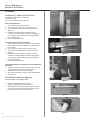
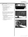
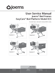
User-Service Manual
Joerns® Bed Frames
EasyCare® Bed Platform Model ECS
To avoid injury, read user’s manual before using.
EasyCare 3
EasyCare 5
EasyCare 7
EasyCare 9
Joerns® Bed Frames
EasyCare® ECS Series
Important Precautions
Warning: Possible Injury Or Death. This product is
intended for use as an adjustable mattress platform that
contours for resident/patient comfort with adjustable height
for resident/patient and caregiver convenience. Use of this
product in a manner for which it was not designed could
result in unproven or unsafe configuration, potentially
resulting in injury or death.
Warning: Possible Injury. Before adjusting bed, ensure
that area under and near bed perimeter is free of people and
obstructions. Failure to do so could result in injury.
Warning: Possible Injury. Keep bed in lowest position
except when providing care (bathing, clothing changes, etc.).
Bed should be at lowest convenient height for entry or exit.
Failure to do so could result in injury.
Warning: Possible Injury Or Death. Resident/patients
may become entangled in pendant cord. Resident/patients
with reduced mental acuity should not be allowed access to
pendant. Unsupervised use of pendant could result in injury
or death.
Warning: Possible Injury Or Death. Bed safe working load
is 500 pounds. This is total weight counting resident/patient,
mattress, bedding accessories and any other equipment or
persons likely to be on bed. Do not exceed 500-pound safe
working load. Exceeding the safe working load could result
in property damage, injury or death.
Warning: Possible Injury Or Death. Do not roll bed over
abrupt thresholds with resident/patient in bed. Bed is not
designed for transporting resident/patient. Transporting
resident/patient in the bed could result in injury or death.
Warning: Possible fire hazard when used with oxygen
administrating equipment other than nasal, mask or ½ bed
length tent type. Not for use with full bed length tent or
hyperbaric oxygen chamber. Oxygen tent should not extend
below mattress support platform. Lock hand control at foot of
bed when using oxygen administering equipment.
Warning: Possible Shock Hazard. Unplug power cord from
wall outlet before performing any maintenance, cleaning or
service to the bed. Failure to do so could result in injury or
death. Note: In case of unexpected movement, unplug bed
from any outlet.
Warning: Possible Shock Hazard. Injury may result from
improper routing of the power cord. Always follow the proper
factory-installed routing configuration. Failure to do so could
result in injury or death.
2
© 2013 Joerns Healthcare • 6110075 RevG • 13-2353
Warning: Possible Injury Or Death. Use a mattress that is
properly sized to fit mattress deck, that will remain centered
on mattress deck relative to State and Federal guidelines.
Joerns Healthcare recommends the use of a mattress with
minimum dimensions of 35 inches wide and 6 inches deep.
Length should match mattress support platform. Use of an
improperly fitted mattress could result in injury or death. If
using Comfort Extension, see Comfort Extension Manual for
proper mattress size.
Warning: Possible Injury Or Death. If a resident/patient’s
mental or physical condition could lead to resident/patient
entrapment, the mattress support platform should be left
in the flat position when unattended. Failure to do so could
result in injury or death.
Warning: An optimal bed system assessment should
be conducted on each resident by a qualified clinician
or medical provider to ensure maximum safety of the
resident. The assessment should be conducted within the
context of, and in compliance with, the state and federal
guidelines related to the use of restraints and bed system
entrapment guidance, including the Clinical Guidance
for the Assessment and Implementation of Side Rails
published by the Hospital Bed Safety Workgroup of the
U.S. Food and Drug Administration. Further information
can be obtained at the following web address: http://www.
fda.gov/MedicalDevices/ProductsandMedicalProcedures/
GeneralHospitalDevicesandSupplies/HospitalBeds/default.
htm.
Warning: Possible Injury Or Death. Use a properly sized
mattress in order to minimize the gap between the side of
mattress and assist device. This gap must be small enough
to prevent resident/patient from getting his/her head or neck
caught in this location. Make sure that raising or lowering
bed, or contouring the sleep surface, does not create any
hazardous gaps. Excessive gaps may result in injury or
death.
Warning: Possible Injury Or Death. Locate mounting
brackets for assist devices strictly according to instructions.
Gap between head/foot panel and assist device must be
small enough or large enough to prevent resident/patient
from getting his/her head or neck caught in this location
(see specific Assist Device Installation Instructions for more
information). If multiple assist devices are used, position
each so that gap between them is large enough for trunk
and hips to pass through easily. Make sure raising or
lowering bed, or contouring sleep surface does not create
any hazardous gaps. Failure to do so could result in injury
or death. Important Note: Powered air mattress surfaces
may pose a risk of entrapment. Prior to use, ensure the
therapeutic benefits outweigh the risk of entrapment.
Joerns® Bed Frames
EasyCare® ECS Series
Warning: Possible Injury Or Death. Do not use an assist
device if any openings within assist device body allow
resident/patient to get his/her head or neck lodged within
these openings. Use of assist devices with large openings
may result in injury or death.
Warning: Possible Injury Or Death. Do not use any
Joerns® assist device until you verify it is locked in place.
Failure to lock assist devices may result in injury or death.
Warning: Possible Injury Or Death. Do not use any
replacement parts not manufactured, marketed or provided
by Joerns Healthcare on any Joerns bed. Use of unapproved
replacement parts may result in injury or death.
Warning: Possible Injury Or Death. If using accessories
not manufactured, marketed or provided by Joerns
Healthcare for Joerns beds, consult with the manufacturer
for compatibility and limitations prior to use. Failure to do so
may result in injury
or death.
Warning: Possible Shock Hazard. If the bed power cord
has a hospital-grade, 3-prong grounding plug, grounding
reliability can only be achieved when equipment is
connected to an equivalent receptacle marked hospitalgrade.
Warning: Possible Injury. Sitting on or sliding over the
Mattress Side Stop can cause skin injury if the bed mattress
compresses to less than 1.5 inches under user’s weight.
Warning: Possible Injury. Risk of entanglement or injury
may occur if mattress used with Mattress Side Stop does not
fill the entire width between stops or which compresses to
less than 1.5 inches under user’s weight.
Warning: Possible Injury or Death. Floor locks increase
bed stability and resident safety. Make sure the bed is in
a locked position with respect to the floor by ensuring the
casters are off the floor or if equipped, the UltraLock is in
the locked position before attempting any resident transfers.
Failure to do so could result in injury or death.
Warning: Possible Injury. Use caution when activating the
UltraLock function. This feature was designed to be activated
by your foot. Using your hand to activate the UltraLock
system could result in injury.
Caution: In the absence of line voltage, all bed adjustments
can be achieved via an externally available backup battery
(Joerns P/N N511). Joerns recommends a minimum of one
battery for every twenty five beds per facility.
Caution: This device complies with EMC requirements
of IEC 60601-1-2. Radio transmitting equipment, cellular
phones or similar electronic devices, used in proximity of
bed, may affect bed performance.
Caution: Particular precaution must be considered
during exposure to strong emission sources such as High
Frequency surgical equipment and similar devices. Do not
route High Frequency cables on or near device. If in doubt,
contact a qualified technician.
Caution: If you have a Joerns® Care 100, or EasyCare®
3 or 5, run the bed frame to either the highest position or
lowest position once a day. This ensures that the bed frame
remains level. Joerns UltraCare® XT, EasyCare 7 and 9 bed
frames have self-leveling electronics and do not require
this procedure.
Caution: The Joerns’ EasyCare® Bed Platform is intended
for use within an institutional healthcare environment
(ie: skilled nursing, transitional care, rehabilitational
care, assisted living). Joerns Healthcare recommends
compliance to the regulations and guidelines specified to
your locality.
This product is only one part of your healthcare bed
system. Proper combinations of mattress, head/foot panels
and assist devices are needed to minimize the risk of
entrapment. For more information, call Customer Care, 800826-0270.
Save These Instructions
Thank you and congratulations for choosing Joerns
EasyCare Bed Platform. Joerns beds are developed with
safety, comfort and convenience of both residents/patients
and caregivers in mind.
Advanced ergonomic design will provide years of reliable
service in your facility.
3
© 2013 Joerns Healthcare • 6110075 RevG • 13-2353
Joerns® Bed Frames
EasyCare® ECS Series
Table of Contents
Important Precautions........................................................................................................................................................................ 2
Entrapment Information...................................................................................................................................................................... 4
Features & Specifications................................................................................................................................................................... 5
Assembly............................................................................................................................................................................................ 6
Operation ........................................................................................................................................................................................... 9
Servicing........................................................................................................................................................................................... 12
Troubleshooting................................................................................................................................................................................ 14
Maintenance..................................................................................................................................................................................... 15
Preventative Maintenance................................................................................................................................................................ 15
Cleaning........................................................................................................................................................................................... 15
Accessories...................................................................................................................................................................................... 16
Warranty........................................................................................................................................................................................... 20
Bed System Entrapment Information
Joerns Compliance Solutions
Although essential in the practice of long-term care, bedside
rails, in recent years, have also been a subject of regulatory
review and evolution in design and use.
Matching the right bed components in order to meet
regulatory guidelines can be complex.
That focus includes not only the challenge of achieving
an appropriate balance between resident security and
unnecessary restraint, but also the additional safety issue of
entrapment.
The U.S. Food and Drug Administration (FDA), working
with our company and other industry representatives has
addressed the potential danger of entrapment with new
safety guidelines for medical beds. These guidelines
recommend dimensional limits for critical gaps and spaces
between bed system components.
Entrapment zones involve the relationship of components
often directly assembled by the healthcare facility rather than
the manufacturer. Therefore, compliance is the responsibility
of the facility.
As the leading manufacturer of long-term care beds and
a frontrunner in addressing this critical issue, Joerns
Healthcare can offer you the expertise, assistance and
products to bring your facility into compliance.
Bed Identification Numbers
When ordering parts or when contacting our Customer
Care Department, please include the bed’s model,
product and serial numbers, found on the identification
labels. The identification labels are located on bed frame
under the sleep deck foot section.
4
© 2013 Joerns Healthcare • 6110075 RevG • 13-2353
®
That is why Joerns offers a wide array of compliance options.
We assist customers in selecting compliant accessories
recommended for their specific bed model.
Creating a Safer Care Environment
While the guidelines apply to all healthcare settings,
(hospitals, nursing homes and at home), long-term care
facilities have particular exposure since serious entrapment
events typically involve frail, elderly or dementia patients.
For More Information
To learn more about compliance options with Joerns
products, visit our website at www.joerns.com, or contact
our Customer Care reps at 800-826-0270 and ask for free
informational publications.
To learn more about entrapment zones, assessment
methods and guidelines concerning entrapment,
contact Joerns Healthcare at 800-826-0270 or
consult the FDA website: http://www.fda.gov/
MedicalDevices/ProductsandMedicalProcedures/
GeneralHospitalDevicesandSupplies/HospitalBeds/default.
htm.
I.D. Label Symbol Definition
Attention, Consult accompanying documents
Safe Working Load
Type B Applied Parts
Class II Equipment
Protective Earth (ground)
Joerns® Bed Frames
EasyCare® ECS Series
Features and Specifications
Standard Features
76" or 80" Sleep Surface
Travel Range:
• EasyCare® 3: 8.25" to 27"
• EasyCare 5, 7, 9: 7" to 30"
Locking System:
• EasyCare 3, 5 and 9: Roll-in-Low Lock System
• EasyCare 7 and 9: UltraLock Roll at any Height Mobility
Pendant Jacks on both left and right side:
• EasyCare 7 and EasyCare 9
Cable connection for optional Staff Control
• EasyCare 7 and EasyCare 9
Whisper Quiet DC Motors
Welded Tubular Frame
Grid Sleep Surface
SoftTone Frame Color
Baseboard Bumper
Wide Stable Base
Heavy-Duty Casters
Mattress Side and End Stops
Patented Lifting Mechanism (US Patent 6473922)
EasyLift Leg Positioner (excludes EasyCare 3)
Battery Pack Cable
Electrical Specifications
EasyCare 3 and EasyCare 5
Power: 120 VAC
Frequency: 60 Hz
Current Rating: 3.5 Amps (120V)
Classification: Class I, Type B or Class II, Type B
Mode of Operation: 10% Maximum Duty Cycle
2 minutes on/18 minutes off
Circuit Protection: LA27 Actuators: Auto Reset
Current Sensor
EasyCare 7 and EasyCare 9
Power: 120 VAC
Frequency: 60 Hz
Current Rating: 4.0 Amps (120V)
Classification: Class I, Type B or Class II, Type B
Mode of Operation: 10% Maximum Duty Cycle
2 minutes on/18 minutes off
Circuit Protection: LA27 Actuators: Auto Reset
Current Sensor
Environmental Conditions
Operating Conditions:
Ambient Temperature: +10°C to +40°C
Relative Humidity: 30% to 75% Non-Condensing
Atmospheric Pressure: 700 hPa to 1060 hPa
Accessories And Options
76", 80" and 84" Joerns® Mattresses
Joerns Bed Panels
F14SC Assist Device Set
F025 Assist Handle
F026 Assist Device
F028 Deluxe Assist Device
Staff Control
IV Rod
Floor Mat
Emergency Battery Backup System
•Battery Backup 24V
•Battery Charger 24V
•Wall Mounting Bracket for Charger
Trapeze and Trapeze Adapter
4" Extension
Drainage Bag Holder
Bed Transport Bar
Mechanical Specifications
Description:Dimensions:
EasyCare 3
76"............................................... 83.0"L x 35.0"W x 8.25"H
80"............................................... 86.5"L x 35.0"W x 8.25"H
EasyCare 5 and EasyCare 7
76"................................................. 83.0"L x 35.0"W x 7.0"H
80"................................................. 86.5"L x 35.0"W x 7.0"H
EasyCare 9
76"................................................. 82.0"L x 35.0"W x 7.0"H
80"................................................. 85.5"L x 35.0"W x 7.0"H
Weight
EasyCare 3 and EasyCare 5..................................220 lbs.
EasyCare 7.............................................................279 lbs.
EasyCare 9.............................................................279 lbs.
Maximum Back Angle................................... 65° to horizontal
Maximum Knee Angle ................................. 35° to horizontal
Maximum Knee To Leg Angle............................................ 45°
Minimum Height Mattress Support Surface
EasyCare 3................................................................. 8.25"
EasyCare 5................................................................. 7.00"
EasyCare 7................................................................. 7.25"
EasyCare 9................................................................. 7.25"
Maximum Height Mattress Support Surface
EasyCare 3............................................................... 27.00"
EasyCare 5............................................................... 30.00"
EasyCare 7............................................................... 30.50"
EasyCare 9............................................................... 30.50"
Safe Working Load.....................................................500 lbs.
Hi-Lo Speed
Unloaded.......................................................... 49 seconds
With 200 lbs...................................................... 52 seconds
Tolerance ± 3 seconds
Storage and Shipping Conditions:
Ambient Temperature: -40°C to +70°C Relative
Humidity: 10% to 100%
Atmospheric Pressure: 500 hPa to 1060 hPa
5
© 2013 Joerns Healthcare • 6110075 RevG • 13-2353
Joerns® Bed Frames
EasyCare® ECS Series
Assembly
Installation Of Head and Foot Panels
Head Panel
Bracket-10.5"
Foot Panel
Bracket-6.9"
(For more information refer to Bed Panel
Installation Sheet)
Tools required: Phillips head screwdriver
Head Panel Installation:
1. The head panel has a label on back.
2. Lay the panel on a soft surface, front face down.
3. The head panel brackets are the longer of two sizes
(Figure 1).
4. Install the head panel brackets with four screws
provided. The bracket offset should face up (Figure 2).
Do not tighten until after fitting the mounting brackets
into the bed sockets.
5. Go to final assembly below.
Frame-Mounted Foot Panel Installation:
1. The foot panel does not have a label on back. The foot
panel will have staff control electronics, if staff control
was ordered.
2. Lay the panel on a soft surface, front face down.
3. The foot panel brackets are the shorter of two sizes
(Figure 1).
4. Install the foot panel brackets with the four screws
provided. The bracket offset should face up (Figure 2).
Do not tighten until after fitting the mounting brackets
into the bed sockets.
5. Go to final assembly below.
Figure 1
Offset facing up
Figure 2
Final Assembly Step for Head Panel and Frame-Mounted
Foot Panel:
1. Insert the head and foot panel as shown with mounting
hardware facing the head of the bed (Figure 3).
2. Tighten all screws with the panels in place.
3. The panels should slip in and out of their sockets easily
and securely.
Installation Of Baseboard Bumper
Recommended Tool: Rubber mallet
Figure 3
1. Place the baseboard bumper as shown (Figure 4). Example shown is EasyCare® 5.
2. Tap into place with a rubber mallet or press firmly with
the sole of your shoe until it locks into place as shown
(Figure 5). Example shown is EasyCare 5.
Figure 4
6
© 2013 Joerns Healthcare • 6110075 RevG • 13-2353
Figure 5
Joerns® Bed Frames
EasyCare® ECS Series
Installation Of Baseboard Bumper
(EasyCare 9 with Advanced Staff Control)
Recommended Tool: Rubber mallet
The bed will ship with the standard bumper installed. If the
12° Trendelenburg Mode is enabled (optional) it will be
necessary to remove the installed bumper and install the 12°
bumper. Note: The 12° bumper can be identified by a silver
label with “12°” printed on it. It is longer than the standard
bumper.
1. Remove the shorter bumper by tapping the tangs on
either side of the leg with a rubber mallet.
2. Place the 12° baseboard bumper.
3. Tap into place with a rubber mallet or press firmly with
the sole of your shoe until it locks
into place.
Figure 6
Installation of Mattress Stop
Mattress Stop is designed to help keep mattress from sliding
laterally on the mattress support platform.
Installation Steps
Required tool - T27 TORX driver
1. Locate the screws in the holes in the inside tube at the
foot end of the mattress support platform (Figure 6).
2. Remove the screws using a T27 torx driver, do not
discard the screws.
3. Position the mattress stop as shown and reinstall the
screws removed in step 2 (Figure 7).
4. Locate the screws in the holes in the inside tube at the
head end of the mattress support platform (Figure 6).
5. Remove the screws using a T27 torx driver, do not
discard the screws.
6. Position the mattress stop as shown and reinstall the
screws removed in step 4 (Figure 7).
Figure 7
IV Socket
IV Sockets
Joerns® EasyCare® Bed Platform has four IV sockets as
standard equipment. There are two sockets at head end
of bed and two at foot end (Figure 8). The IV sockets are
compatible with Joerns IV poles and most ½" IV poles.
Figure 8
7
© 2013 Joerns Healthcare • 6110075 RevG • 13-2353
Joerns® Bed Frames
EasyCare® ECS Series
Installation of Staff Control Panel
(Optional)
EasyCare® 3 and 5 (Figure 9)
1. Mount foot panel on bed as indicated in
previous instructions.
2. Plug cable from the control box and the cable from the
pendant into the proper sockets on the foot panel as
shown (Figures 10 and 11).
3. Attach circuit board cover (not shown) with Velcro®
according to instructions included with staff control panel
assembly.
EasyCare 7 and 9 (Figure 12)
1. Mount the foot panel on the bed as indicated in previous
instructions.
2. Unscrew the cap located under the bed frame at the
foot end (Figure 13), and secure the cable plug, with the
arrow facing up into the jack (Figure 14).
3. Ensure that the cable plug is fully inserted into the jack
(Figure 15).
4. Screw on the cap from the cable to secure the cable
(Figure 16).
Figure 12
Figure 13
Arrow up
Figure 14
Figure 9
Figure 15
Figure 10
To Control Box
8
To Pendant
Figure 11
© 2013 Joerns Healthcare • 6110075 RevG • 13-2353
Figure 16
Joerns® Bed Frames
EasyCare® ECS Series
Operation
Pendant Operation
EasyCare 3 and 5
Your Joerns® EasyCare 3 or EasyCare 5 bed comes with the
EasyCare Plus pendant shown below (Figures 17).
EasyCare 3 and 5 Pendant
Operation (Figure 17)
Head Operation
1 - Push button to raise Back
2 - Push button to lower Back
Knee Operation
3 - Push button to raise Knee
4 - Push button to lower Knee
Bed Height Operation
5 - Push button to raise Bed
6 - Push button to lower Bed
EasyCare 7 or 9 Standard
Pendant Operation (Figure 18)
1
3
2
4
EasyCare® 7 and 9
1. Your EasyCare 7 or EasyCare 9 bed comes standard
with a pendant (Figure 18 and 19). The pendant plugs
into a jack under either side of the seat pan.
2. Unscrew the cap (Figure 20) and insert the
cable plug, with the arrow facing up into jack (Figure
21).
3. Ensure that the cable plug is fully inserted into the jack
(Figure 22).
4. Screw on the cap from the cable to secure cable
(Figure 23).
5. The pendant has raised, high-contrast buttons and
graphics.
5
6
Figure 17
1
3
2
4
Figure 20
Head Operation
1. Push button to raise Back
2. Push button to lower Back
5
Knee Operation
3. Push button to raise Knee
4. Push button to lower Knee
6
Bed Height Operation
5. Push button to raise Bed
EasyCare 9 Advanced Pendant
Operation (Figure 19)
Head Operation
1. Push button to raise Back
2. Push button to lower Back
Knee Operation
3. Push button to raise Knee
4. Push button to lower Knee
Bed Height Operation
5. Push button to raise Bed
6. Push button to lower Bed
Comfort Chair Operation
7. Push button for Comfort Chair
8. Push button to lower both head
and knee to flat and place bed at
transfer height
Figure 21
Figure 18
1
3
2
4
5
7
Figure 22
6
8
Figure 19
Figure 23
9
© 2013 Joerns Healthcare • 6110075 RevG • 13-2353
Joerns® Bed Frames
EasyCare® ECS Series
Staff Control Panel Operation (Optional)
EasyCare® 3 and 5 (Figure 24)
The Staff Control Panel allows caregivers to lock out all of
the bed functions individually. Caregivers can also operate
the bed from this panel without walking to the bed side.
1. To lock out a function, press panel’s “no pendant”
(Figure 24: #1, #3 and #5) icon. Illuminated red LED
light indicates that the function is now locked out.
2. To unlock a function, press panel’s “pendant” (Figure 24:
#2, #4 and #6) icon. Red LED is no longer illuminated,
signaling that the pendant can now operate that specific
function.
EasyCare 7 and 9 (Figure 25 and 26)
The Staff Control Panel allows the caregivers to operate the
bed from the foot panel without walking to the bedside. The
caregiver can also individually lock out all functions, both
Pendant and Staff Control.
1. To lock out a function, press and hold the “Lock”
graphic on the panel and push the function to lock out.
Illuminated amber LED indicates that the function is now
locked out.
2. To unlock a function, press and hold the “Lock” graphic
on the panel and push the function to unlock. Amber
LED is no longer illuminated, signaling that the function
is now operable.
Setting 12 Degree Trendelenburg Mode
(EasyCare 9 with Advanced Staff Control)
The bed will ship set to 4° Advanced Positioning
mode. This mode limits the head down angle to 4°.
The software can be changed to 12° Trendelenburg mode to
2
7
8
4
1
9
10
6
11
3
12
5
Figure 24
EasyCare 3 and 5 Staff Control
Push button to:
1. Lock out Back
7. Raise Back
2. Unlock Back
8. Lower Back
3. Lock out Knee
9. Raise Knee
4. Unlock Knee
10.Lower Knee
5. Lock out Hi/Lo
11.Raise Bed
6. Unlock Hi/Lo
12.Lower Bed
1
3
5
7
2
4
6
Figure 25
EasyCare 7 or 9 Standard Staff Control
1.
2.
3.
4.
5.
6.
7.
Push button to raise Back
Push button to lower Back
Push button to raise Knee
Push button to lower Knee
Push button to raise Bed
Push button to lower Bed
Push and hold to change lockout status in combination
with another function button.
enable Trendelenburg functionality.
1. Install Advanced Staff Control Panel described.
2. Simultaneously, press and hold Trendelenburg (Button
10, Figure 26) and reverse Trendelenburg (Button 11,
Figure 26) buttons for 5 seconds on Advanced Staff
Control Panel.
3. Trendelenburg/Reverse Trendelenburg lock icon
will begin flashing indicating that the system is in
programming mode.
4. Press bed up (Button 5, Figure 26) button to select full
12° Trendelenburg mode.
5. Bed Hi-Low lock out icon will flash twice confirming
software is set to 12° Trendelenburg mode. Note: Be
sure correct baseboard bumper is installed. Failure
to install the correct baseboard bumper can result in
damage to the bed or walls. The 12° bumper is identified
by a silver label with “12°” printed on it.
6. To return bed to 4° Advanced Positioning, repeat steps 2
and 3 then press bed down (Button 6, Figure 26). Bed
Hi-Low lock icon will blink once confirming software is
now in 4 Degree Advanced Positioning mode. Install
correct baseboard bumper.
10
© 2013 Joerns Healthcare • 6110075 RevG • 13-2353
1
3
5
8
10
7
12
2
4
6
9
11
Figure 26
EasyCare 9 Advanced Staff Control
1. Push button to raise back
2. Push button to lower back
3. Push button to raise knee
4. Push button to lower knee
5. Push button to raise bed
6. Push button to lower bed
7. Push and hold to change lockout status in combination
with another function button.
8. Push button for Comfort Chair
9. Push button to lower both head and knee to flat and place
bed at transfer height
10. Push button for Trendelenburg
11. Push button for reverse Trendelenburg
12. Push button to toggle under bed light on and off (optional)
Joerns® Bed Frames
EasyCare® ECS Series
Roll in Low Lock System
EasyCare 3, 5, and 9
1. To keep the bed from rolling when in the lowest position,
press down on the locking lever to lock casters (Figure
27).
2. The standard caster set comes with two locking casters
placed at opposing corners of bed.
Mobile
Roll in
Low only
Low Lock
System
Locked
Position
Swivel
Casters
Any Height
(casters must
be locked in
Low)
Head &
Foot (in Low
position
only)
Figure 27
UltraLock System
EasyCare® 7 and 9
The Joerns® UltraLock feature provides roll at any height
functionality to the EasyCare 7 and EasyCare 9 bed frame.
• The EasyCare 7 and EasyCare 9 beds are equipped
with a single UltraLock. The foot end has swivel casters
when the UltraLock is engaged and rollers at the head.
Figure 28
1. There are three possible locations with which to operate
the UltraLock on each UltraLock assembly (Figure 28).
2. To lock the bed using the UltraLock, place your toe
under the pedal and lift upward (Figure 29). The label
indicates the locked position by a red symbol (Figure
30).
3. To unlock the UltraLock, place the ball of your foot
on any pedal and push down (Figure 31). The label
indicates the mobile position by a green symbol (Figure
30).
Warning: Possible Injury. Before leaving the bed
unattended, check that the UltraLock feature is in the locked
position. Never leave an unlocked bed unattended.
Figure 29
Warning: Possible Injury. Check that the UltraLock feature
is in the locked position before allowing the resident to enter
or exit the bed.
For best practices, the UltraLock feature should be locked at
all times, except when the bed is
being moved.
Figure 30
Figure 31
11
© 2013 Joerns Healthcare • 6110075 RevG • 13-2353
Joerns® Bed Frames
EasyCare® ECS Series
EasyLift Leg Positioner Operation
EasyCare® 5, 7 and 9
1. To raise: Grasp the bed’s foot deck and raise to the
desired position (Figure 32).
2. To lower: Grasp the foot end of the bed’s deck and
raise ½-inch to ¾-inch above present notch, then lower
gently;
3. Or, grasp the foot end of the bed deck, raise to the
highest position, and lower gently.
Figure 32
Servicing
1
EasyCare 3 and 5
2
Warning: Possible Shock Hazard. Unplug the power cord
from the wall outlet before performing any maintenance/
service to the control box.
Note: Overload protection is achieved via current sensing
technology, which will reset automatically if any bed function
fails to operate. Ensure that the bed is not overloaded or
constrained from movement.
Actuator and Control Box Information
Cable and Port Identification (Figures 33 and 34)
1. Back Actuator (yellow)
2.
Knee Actuator (blue)
3.
Hi-Lo Actuator (red)
4.
Hi-Lo Actuator (red)
HB. Pendant (green)
B.
Emergency Battery Pack
C.
AC Power
Power Cord and Grounding Connectors
Inspection of power cord and grounding connectors should
be conducted on a yearly basis to ensure efficient bed
operation.
1. Check the power cord to make sure it has not been
damaged. If the power cord needs replacement due
to damage, remove the bed from use/service until the
power cord has been replaced.
2. Check the grounding connectors to ensure they remain
intact and are securely fastened to their intended
connection point.
12
© 2013 Joerns Healthcare • 6110075 RevG • 13-2353
Figure 33
1
2
3
HB
4
B
C
Figure 34
3
4
HB
Joerns® Bed Frames
EasyCare® ECS Series
EasyCare® 7 and 9
1
2
3
4
5
Warning: Possible Shock Hazard. Unplug the power cord
from the wall outlet before performing any maintenance or
service to the Control Box.
Actuator And Control Box Information
Cable and Port Identification (Figures 35 and 36)
1. Foot Leg Hi/Low Actuator (red)
2. Back Actuator (yellow)
3. Head Leg Hi/Low Actuator (orange)
4. Knee Actuator (blue)
5. Control Harness (green)
6. Emergency Battery Pack
7. AC Power
Note: The Actuators and Control Box contain no serviceable
parts. Overload protection is achieved via current sensing
technology, which will automatically reset. If any bed function
fails to operate, check to see if the bed is overloaded or
constrained from movement.
To Remove Control Box
1. Plugs and outlets are numbered and color-coded so
they can be easily reinstalled later (See Actuator And
Control Box Information).
2. Unplug from wall outlet.
3. Unplug all actuator cords and pendant/staff control plug.
4. Remove the control box retaining clip
(Figure 37).
5. Slide the Control Box off the actuator assembly.
6. To replace the Control Box, reverse
these instructions.
Figure 35
6
7
Figure 36
Figure 37
13
© 2013 Joerns Healthcare • 6110075 RevG • 13-2353
Joerns® Bed Frames
EasyCare® ECS Series
To Remove Actuator
Recommended Tools: Screwdriver, Hammer,
Masking Tape, Zip Ties
1.
2.
3.
4.
Identify the actuator to be replaced.
Tip the bed on its side to replace high/low actuator(s).
Unplug the actuator cord.
The actuator is held in place by two pins. Use a
screwdriver to remove the lock ring on each pin.
5. Slide the pins out of holes. If necessary, use the
hammer to tap out the pins.
6. You may now replace the actuator(s).
7. To reassemble the bed, reverse the previous steps,
making note of the following two important items:
• Assemble the pin and lock rings as
originally installed.
• Zip-ties should be replaced, with cords returned to
their original position and routing direction to the
control box.
To Remove AC Power Cable
Recommended Tools: Small Screwdriver, Masking Tape, Zip
Ties, 5/16" Nut Driver
1. Raise the bed so that there is about 27 inches of
clearance between the floor and the mattress support
platform of bed.
2. Unplug the power cable from the outlet.
3. Cut the zip-ties that hold the power cable to the frame.
Tape the remaining cables in their original position. It is
very important to keep the actuator cables routed along
the frame in their original factory-installed positions. If
this step is not followed, damage to cables or electric
shock may result.
4. Detach the ground wire from the bed frame
if equipped.
Warning: Possible Shock Hazard. Injury may result from
improper power cable routing. Always follow proper factoryinstalled routing configuration. Be sure to check condition of
the power cable on a regular basis. Do not use damaged or
frayed power cables.
5. Using a small screwdriver, alternately depress the small
red latch tabs above and below AC receptacle on the
control box. Simultaneously, pull gently outward on the
power cable where it connects to the control box, until
the plug comes out.
6. Plug the replacement cable into the control box until it
latches. Attach the ground wire to the bed frame.
7. Re-route the power cable along the frame in the same
position as the original routing.
8. Replace zip-ties along with cables in their original
position and routing to the control box. If this step is not
followed, damage to the cables or electric shock may
result.
14
© 2013 Joerns Healthcare • 6110075 RevG • 13-2353
Troubleshooting
Any loss of electrical function should be investigated with the
following steps:
Event
Possible Remedies
Bed not
responding
to pendant
control
1. Check lockout status.
2. Check connection is fully inserted
with cable secured.
3. Check the bed is plugged into power
source and control box green light is
illuminated
4. Switch the pendant with a new
pendant or one from a bed that is
functioning normally.
5. If these steps fail to resolve the
problem, call Technical Support at
800-826-0270.
Bed not
responding to
Staff Control
1. Check lockout status
2. Check connection is fully inserted
with cable secured.
3. Check the bed is plugged into power
source and control box green light is
illuminated.
4. If these steps fail to resolve the
problem, call Technical Support
at 800-826-0270.
All Staff
Control lockout
indicators
flashing
(EasyCare® 7
and 9)
1. Unplug bed for 60 seconds
and plug back in.
2. Push and hold Hi-Lo up and
down on staff control or pendant
simultaneously until flashing stops
(No more than 15 seconds).
3. If these steps fail to resolve the
problem, call Technical Support
at 800-826-0270.
Staff Control
Hi-Lo lockout
indicator
flashing
(EasyCare 7
and 9)
1. Thermal overload condition. This
should self-correct in 2 minutes or
less. Do not surpass 10% duty cycle
(2 min on/ 18 min off).
2. If these steps fail to resolve the
problem, call Technical Support
at 800-826-0270.
Note: Electrical damage can occur if a non-approved
pendant is connected to the electrical system.
Joerns® Bed Frames
EasyCare® ECS Series
Maintenance
Maintenance/inspection Information:
Visually inspect the bed and accessories for broken
welds or cracks and check for loose hardware on a
monthly basis.
If any broken welds or cracks are found, remove bed
from service immediately and replace affected part(s). If
necessary, contact Technical Support, 800-826-0270, for
assistance. Tighten any loose hardware.
Preventative Maintenance
To ensure maximum life of your product, follow all warnings
and cautions in the User Manual and maintain your bed
with care, as outlined below. The maintenance required
will be dictated by your bed’s usage and care – a thorough
inspection should be conducted monthly.
To Maximize Service Life
1. If you have a Joerns® Care 100, or EasyCare® 3 or 5,
run the bed frame to either the highest position or lowest
position once a day. This ensures that the bed frame
remains level. Joerns UltraCare® XT, EasyCare 7 and
9 bed frames have self-leveling electronics and do not
require this procedure.
2. Keep the bed clean.
3. Observe bed operation and report any discrepancies
or problems to Joerns Healthcare Technical Support at
800.826.0270
4. After initial week of use, check all threaded fasteners for
looseness, and make sure all pins are in their normal
location and fastened securely. Check monthly for loose
bolts, nuts, pins and other retaining hardware. Tighten
any loose hardware, and contact Joerns Healthcare to
order any appropriate service parts.
5. Make sure each inspection includes the underside of the
bed frame and mattress support platform.
6. Visually inspect the bed frame and accessories for any
cracking, bending, or hole enlargement. If found, contact
Joerns Technical Support at 800.826.0270, remove the
bed from service immediately, and replace the affected
parts.
7. Check wiring for proper connections and damage
(fraying, kinking, or deterioration). Report any damage
to Joerns Technical Support at 800.826.0270
8. Check actuators for correct mounting at attachment
points and ensure all related pins are mounted securely
and properly to the bed frame. Actuators are not
serviceable, but are replaceable if required.
9. Lubricate pivot point, pins and bolts as required. The
recommended lubricant is Joerns-approved grease
#12500013, available from Joerns Technical Support at
800.826.0270.
If any discrepancies are noted during inspection, they
must be corrected before continuing bed frame use. Major
service and repairs must be performed by authorized Joerns
Healthcare Technical Support, which you may contact at
800.826.0270.
Cleaning
Caution: Possible damage to electrical parts, and/or shock
hazard.
1. Clean all the electrical components (motors, control box,
pendant and cords) on your Joerns® bed with damp,
well-wrung out cloth. Excess water in or on electrical
parts, could damage these components. Do not
submerge the pendant in liquid.
2. Your Joerns bed features a durable, baked-on epoxy
finish that is easily cleaned with a mild solution of
antiseptic cleaner and warm water. Read and follow all
label instructions on your cleaning products.
3. Wood veneer surfaces should be maintained by
cleaning with furniture cleaner or polish.
15
© 2013 Joerns Healthcare • 6110075 RevG • 13-2353
Joerns® Bed Frames
EasyCare® ECS Series
Accessories
Drainage Bag Holder
All Accessories
Warning: Possible BioHazard. Prior to use, consult the
Drain Bag manufacturer’s installation and use instructions.
Failure to do so could result in a bag puncture, resulting in a
potential biohazard.
Warning: Possible Injury Or Death. Injury or death may
result from improper use of bed accessories. Consult
accessory manufacturer for compatibility, proper installation
and
use instructions.
Trapeze And Trapeze Adapter
Warning: Possible Injury Or Death. Improper installation of
the Trapeze Adapter could alter or dislodge the head panel
position, increasing the risk of injury or suffocation.
Warning: Possible Injury Or Death. Follow the
manufacturer’s directions when installing the Trapeze Bar.
Improper installation of the Trapeze Bar on the Trapeze
Adapter could cause the Trapeze Bar to disconnect/collapse
or otherwise fail, resulting in injury or death.
Warning: Possible Injury Or Death. A minimum of 1-inch
clearance between the bottom of the Trapeze Bar and the
floor is required when the bed is in its lowest position. Failure
to do so could damage the floor and/or cause the bed to
become unstable, resulting in injury or death.
4-Inch Extension
Warning: Possible Injury Or Death. Use a mattress long
enough so the gap between the mattress and head/ foot
panel is small enough to prevent the resident from getting
his/her head or neck caught in these locations. Failure to
do so could increase risk of suffocation or result in injury or
death.
Warning: Possible Injury. The extender is designed for
use with a foot panel. Sitting on or sliding over the extender
without a foot panel installed could cause the extender to fail,
resulting in injury or death.
16
© 2013 Joerns Healthcare • 6110075 RevG • 13-2353
Warning: Possible Injury Or Death. Many items that attach
to the Holder are gravity fed and must be below the bed user
to function. Do not allow items attached to the Holder to rest
or be positioned on the floor where they might be stepped
on and adversely affected or damaged. Exercise particular
caution when the bed is moved to its lowest position as
items attached to the Holder at that height are especially at
risk. Failure to do so could result in injury or death.
Warning: Possible Injury Or Death. Make sure items hung
on this holder have proper clearance and are not pinched or
caught during bed adjustment. Failure to do so could result
in injury or death.
Bed Transport Bar
Warning: Possible Injury. The Bed Transport Bar must be
used according to installation and user instructions. Improper
use could cause it to disconnect, resulting in a fall or loss of
control of
the bed.
Joerns® Bed Frames
EasyCare® ECS Series
Trapeze (Figure 38)
1. We recommend using the Joerns® Trapeze with the
Joerns Trapeze Adapter.
2. Install the Trapeze assembly according to
manufacturer’s directions included with the Trapeze.
Trapeze Adapter (Figure 39)
1. The Trapeze Adapter is designed to allow attachment of
the Trapeze system to the EasyCare® Bed. Prior to use,
please read important warnings related to this option
and follow all instructions below.
2. Install the Trapeze Adapter according to the supplied
instructions. If needed, call Technical Support at 800826-0270 for instructions.
3. Install the trapeze assembly onto the Trapeze Adapter
according to the trapeze manufacturer’s instructions.
4. Operate the bed from its highest through lowest
positions to ensure proper clearance and operation.
Some trapeze systems may not be suitable for use with
the EasyCare Bed, due to its low operating height.
5. Adjustment and use of a Trapeze should be in
accordance with instructions from a healthcare
professional (doctor or therapist).
6. Do not exceed the maximum load condition listed on
installation instructions.
Figure 38
4-Inch Extender (Figure 40)
1. The 4-Inch Extender is designed to extend the mattress
support platform about four inches to allow the use of
an 84-inch mattress on an 80-inch mattress support
platform or an 80-inch mattress on a 76-inch mattress
support platform. Prior to use, please read important
warnings related to the Extender and follow instructions
below.
2. Install the 4-Inch Extender according to supplied
instructions. If needed, call Technical Support at 800826-0270 for instructions.
3. Make sure the increase in overall length does not
produce a safety hazard or impair accessibility in the
room. Place the new mattress against the Mattress Stop
and be sure the mattress covers the entire mattress
support platform length.
Figure 39
Figure 40
17
© 2013 Joerns Healthcare • 6110075 RevG • 13-2353
Joerns® Bed Frames
EasyCare® ECS Series
Drainage Bag Holder (Figure 41)
1. The Drainage Bag Holder is designed as an attachment
point for items such as urine collection bags. Make
sure items attached to holder are safely secured. Prior
to use, please read important warnings related to the
Drainage Bag Holder and follow all instructions below.
2. Install the Drainage Bag Holder and attach
items to the Holder according to supplied instructions. If
needed, call Technical Support
at 800-826-0270 for instructions.
3. It is important to operate all bed functions through their
entire ranges to ensure that items attached to the Holder
have proper clearance and are not pinched or caught.
4. Attach the Holder only to the point and position outlined
in installation instructions. Operate all bed functions
through their full ranges to ensure that items attached to
the Holder have proper clearance and are not pinched
or caught.
5. Many items that attach to the Holder are gravity fed
and must be below bed user to function. Do not allow
items suspended from the Holder to rest on the floor,
particularly when the bed is in its lowest position.
Otherwise, a safety condition may occur or the function
of attached items may be impacted.
Bed Transport Bar (Figure 42)
1. The Bed Transport Bar is designed to ease moving
the EasyCare® Bed, particularly when it is lowered onto
its casters. Note: The EasyCare Bed is not designed
for use as resident/patient transport devices. Prior to
use, please read important warnings related to the Bed
Transport Bar and follow all instructions below.
2. Install the Bed Transport Bar according to the supplied
instructions. If needed, call Technical Support at 800826-0270 for instructions.
3. When using the Bed Transport Bar to move beds,
always push down and forward on the handle. Pushing
up or attempting to use the Bed Transport Bar to lift the
bed, especially when crossing over thresholds, may
cause it to disconnect from the bed, resulting in loss of
control of the bed.
4. Take extra care when moving the bed (remember, do
not move the bed while occupied by the resident) on
any sloped surface. Moving a bed on a sloped surface
requires two people, one at each end of the bed.
Never use the Bed Transport Bar to move the bed on a
slope that exceeds ANSI and/or ADA requirements for
accessibility.
Figure 42
Figure 41
18
© 2013 Joerns Healthcare • 6110075 RevG • 13-2353
Joerns® Bed Frames
EasyCare® ECS Series
Battery Back-up
Battery Backup Includes:
•
•
•
•
Charger with Power Cord (with Cord Clip)
Battery with Cable
Wall Mount Bracket (with two screws)
User Instructions
Battery Charger
1. Simply mount the Battery Charger in a central
2.
3.
4.
5.
location convenient to caregiver staff. Plug the Battery
Charger into any standard wall socket (110V; 50-60
Hz.).
Insert the Battery in the Battery Charger.
• Green light -- indicates main power is on
• Yellow light -- indicates Battery is charging
After about four hours of charging, the yellow light
goes off and the Battery will be fully charged. Note:
We recommend that users charge up the Battery
immediately upon receipt.
The Battery has a useful life of about 3.5 years,
depending upon usage. It is recommended to discharge
the Battery as little as possible and to recharge quite
frequently (by keeping the Battery connected to the
Battery Charger when not in use), to provide the longest
Battery life.
When the Battery needs replacing, dispose of the old
Battery in the same manner you would dispose of a car
(lead acid) battery.
Figure 43
Powering the EasyCare Bed with
Battery Backup:
Attach the battery to the Battery Pack Patch Cord Socket at
the bed foot end (Figure 43).
Depending on the Battery condition and load on the bed, one
battery can typically raise and lower the bed, constituting one
cycle, 20 to 25 times on single, full charge.
19
© 2013 Joerns Healthcare • 6110075 RevG • 13-2353
Joerns Healthcare Warranty Program
for Joerns® EasyCare® Series Bed, Model ECS
Joerns EasyCare 3, 5, and 7 are guaranteed for a period of
three years and the EasyCare 9 is guaranteed for a period
of four years from the date of delivery, against defects in
materials and workmanship, under normal use and service.
Joerns Healthcare’s obligation under this warranty is limited
to supplying replacement parts, servicing or replacing, at its
option, any product which is found by Joerns Healthcare to
be defective.
This three-year warranty includes all mechanical and
electrical components.
Warranty replacement parts are covered by the terms of
this warranty until the product’s original three-year warranty
period expires.
Steel structural components on beds are covered under
warranty for a period of 15 years from the date of delivery.
When requested by Joerns Healthcare, parts must be
returned for inspection at the customer’s expense. Credit will
be issued only after inspection.
Welds are covered under warranty for the lifetime1 of the
product.
Damage caused by use in unsuitable environmental
conditions, abuse or failure to maintain the product in
accordance with user and service instructions is not covered.
Any alteration, modification, or repair unless performed by,
or authorized in writing by, Joerns Healthcare, will void this
warranty.
Parts
Joerns beds contain various parts that wear from normal
use. These parts, such as DC batteries, are not covered
under the three-year warranty but are covered for 90 days
after date of delivery.
Service
Most service requests can be handled by the facility
Maintenance Department with assistance from the Joerns
Healthcare Product Service Department.
Most parts requested can be shipped next day air at the
customer’s expense.
Should a technician be required, one will be provided
by Joerns Healthcare, at our discretion. Only the Joerns
Healthcare Product Service Department can dispatch
authorized technicians.
This warranty is extended to the original purchaser of the
equipment.
1
Weld lifetime defined as 20 years.
Post Acute, Acute, HomeCare
2430 Whitehall Park Dr. Ste 100
Charlotte, NC 28273
(P) 800.826.0270
(F) 800.457.8827
www.joerns.com • email: [email protected]
VA/Government
19748 Dearborn Street
Chatsworth, CA 91311
(P) 800.966.6662
(F) 800.232.9796
Canadian Office
1000 Clarke Rd. Ste 6
London, ON Canada N5V 3A9
(P) 866.546.1151
(F) 519.451.8662
United Kingdom and
Other Countries
+44 (0)844 811 1156
+44 (0)844 811 1157
Netherlands
+31 (0)30 6363700
+31 (0)30 6363799
© 2013 Joerns Healthcare • 6110075 RevG • 13-2353