1
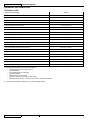
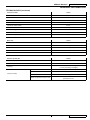
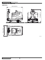
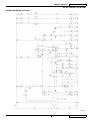
TerraTM 4300B
SERVICE MANUAL
Advance model: 908 4309 010
1463200000(2)2008-07
SERVICE MANUAL
ENGLISH
INDEX
INDEX
GENERAL INFORMATION . ....................................................................................................................................... 3
MACHINE LIFTING ................................................................................................................................................ 3
MACHINE TRANSPORTATION ............................................................................................................................. 3
PUSHING OR TOWING THE MACHINE ............................................................................................................... 3
OTHER REFERENCE MANUALS AVAILABLE ..................................................................................................... 3
SAFETY ................................................................................................................................................................. 3
GENERAL SAFETY PRECAUTIONS .................................................................................................................... 4
TECHNICAL DATA ................................................................................................................................................. 6
MAINTENANCE ..................................................................................................................................................... 9
SCHEDULED MAINTENANCE............................................................................................................................... 9
SCHEDULED MAINTENANCE TABLE .................................................................................................................. 9
MACHINE NOMENCLATURE .............................................................................................................................. 10
SWEEPING SYSTEM................................................................................................................................................ 13
MAIN BROOM HEIGHT CHECK AND ADJUSTMENT......................................................................................... 13
MAIN BROOM DISASSEMBLY/REASSEMBLY.................................................................................................... 13
SIDE BROOM HEIGHT CHECK AND ADJUSTMENT.......................................................................................... 14
SIDE BROOM DISASSEMBLY/REASSEMBLY.................................................................................................... 16
SIDE BROOM LIFTING CABLE DISASSEMBLY/REASSEMBLY......................................................................... 17
MAIN BROOM DRIVING BELT VISUAL INSPECTION........................................................................................ 18
MAIN BROOM DRIVING BELT DISASSEMBLY/REASSEMBLY.......................................................................... 19
MAIN BROOM GAS SPRING DISASSEMBLY/REASSEMBLY............................................................................ 20
MAIN BROOM PULLEY BEARING REPLACEMENT........................................................................................... 21
MAIN BROOM MOTOR ELECTRICAL INPUT CHECK........................................................................................ 22
MAIN BROOM MOTOR CARBON BRUSH CHECK AND REPLACEMENT......................................................... 23
MAIN BROOM MOTOR DISASSEMBLY/REASSEMBLY..................................................................................... 28
SIDE BROOM MOTOR ELECTRICAL INPUT CHECK......................................................................................... 25
SIDE BROOM MOTOR CARBON BRUSH CHECK AND REPLACEMENT......................................................... 26
SIDE BROOM MOTOR DISASSEMBLY/REASSEMBLY...................................................................................... 27
SIDE BROOM ACTIVATION MICROSWITCH ADJUSTMENT AND DISASSEMBLY/REASSEMBLY.................. 28
MAIN BROOM ACTIVATION MICROSWITCH ADJUSTMENT AND DISASSEMBLY/REASSEMBLY................. 29
TROUBLESHOOTING.......................................................................................................................................... 30
SKIRT......................................................................................................................................................................... 31
SKIRT HEIGHT AND OPERATION CHECK AND ADJUSTMENT........................................................................ 31
SIDE SKIRT DISASSEMBLY/REASSEMBLY....................................................................................................... 33
REAR SKIRT DISASSEMBLY/REASSEMBLY...................................................................................................... 34
FRONT SKIRT DISASSEMBLY/REASSEMBLY................................................................................................... 35
FRONT SKIRT LIFTING CABLE DISASSEMBLY/REASSEMBLY........................................................................ 36
TerraTM 4300B
146 2889 000(2)2007-08
1
ENGLISH
SERVICE MANUAL
INDEX
DUST AND DEBRIS COLLECTION SYSTEM.......................................................................................................... 37
DUST FILTER CLEANING AND INTEGRITY CHECK.......................................................................................... 37
FILTER SHAKER OPERATION CHECK............................................................................................................... 39
FILTER SHAKER MOTOR DISASSEMBLY/REASSEMBLY................................................................................. 39
VACUUM FAN DISASSEMBLY/REASSEMBLY
[till S/N 072820295]............................................................................................................................................... 40
POWER VACUUM FAN DISASSEMBLY/REASSEMBLY
[starting from S/N 072820296].............................................................................................................................. 41
TROUBLESHOOTING.......................................................................................................................................... 42
STEERING AND BRAKING SYSTEM....................................................................................................................... 43
STEERING CHAIN CHECK AND CLEANING...................................................................................................... 43
STEERING CHAIN DISASSEMBLY/REASSEMBLY............................................................................................. 44
SERVICE AND PARKING BRAKE CHECK AND ADJUSTMENT......................................................................... 45
BRAKE CONTROL CABLE REPLACEMENT....................................................................................................... 46
BRAKE SYSTEM DISASSEMBLY/REASSEMBLY............................................................................................... 47
DRIVE SYSTEM......................................................................................................................................................... 48
DRIVE SYSTEM DRIVE MOTOR ELECTRICAL INPUT CHECK......................................................................... 48
DRIVE MOTOR CARBON BRUSH CHECK AND REPLACEMENT..................................................................... 49
DRIVE SYSTEM DISASSEMBLY/REASSEMBLY................................................................................................ 50
DRIVE MOTOR DISASSEMBLY/REASSEMBLY.................................................................................................. 51
FORWARD/REVERSE GEAR PEDAL DISASSEMBLY/REASSEMBLY............................................................... 52
FORWARD/REVERSE GEAR PEDAL POTENTIOMETER CHECK AND ADJUSTMENT .................................. 53
TROUBLESHOOTING.......................................................................................................................................... 54
TABLE OF DRIVE BOARD ERROR CODES........................................................................................................ 55
OTHER SYSTEMS..................................................................................................................................................... 56
SCREW AND NUT TIGHTENING CHECK............................................................................................................ 56
FRONT COVER DISASSEMBLY/REASSEMBLY................................................................................................. 57
SEAT RUNNING CONSENT MICROSWITCH DISASSEMBLY/REASSEMBLY................................................... 59
ELECTRICAL SYSTEM............................................................................................................................................. 60
BATTERY CHARGING.......................................................................................................................................... 60
FUSE REPLACEMENT......................................................................................................................................... 60
DRIVE ELECTRONIC BOARD DISASSEMBLY/REASSEMBLY.......................................................................... 60
TROUBLESHOOTING.......................................................................................................................................... 61
COMPONENT LOCATION.................................................................................................................................... 61
WIRING DIAGRAM............................................................................................................................................... 64
2
146 2889 000(2)2007-08
TerraTM 4300B
SERVICE MANUAL
ENGLISH
GENERAL INFORMATION
GENERAL INFORMATION
CONVENTIONS
Front, rear, right or left indications in this manual are intended with reference to the operator’s driver’s seat position.
MACHINE LIFTING
WARNING!
Do not work under the lifted machine without supporting it with safety stands.
MACHINE TRANSPORTATION
WARNING!
Before transporting the machine, make sure that:
–– All doors and carters are closed
–– The ignition key is not inserted
–– The machine is securely fastened to the means of transport
PUSHING OR TOWING THE MACHINE
WARNING!
When pushing or towing the machine, carefully follow the relevant instructions given in the User Manual. If you
do not follow the given instructions the machine can be damaged.
OTHER REFERENCE MANUALS AVAILABLE
The following manuals are available at Advance Literature Service Department:
–– TerraTM 4300B Part List - Advance Form Number 146 2811 000
–– TerraTM 4300B User Manual - Advance Form Number 146 2810 000
––
––
––
––
––
––
––
––
Installation instruction for Kit aspiratore Comex - Form Number 1463196000
Installation instruction for Kit battery charger - Form Number 146 2055 000
Installation instruction for Kit remote vacuum - Form Number 146 2523 000
Installation instruction for Kit working light - Form Number 146 2526 000
Installation instruction for Kit brush bumper - Form Number 146 2698 000
Installation instruction for Kit overhead guard - Form Number 146 2738 000
Installation instruction for Kit carpet - Form Number 146 2742 000
Installation instruction for Kit flashing beacon - Form Number 146 2693 000
SAFETY
Advance uses the following symbols to indicate potentially dangerous situations. Always read this information carefully and take all
necessary precautions to safeguard people and property.
DANGER!
It indicates a dangerous situation with risk of death for the operator.
WARNING!
It indicates a potential risk of injury for people.
CAUTION!
It indicates a caution or a remark related to important or useful functions. Pay the greatest attention to the
paragraphs marked by this symbol.
NOTE
It indicates a note related to important or useful functions.
CONSULTATION
It indicates the necessity to refer to the User Manual before performing any procedure.
TerraTM 4300B
146 2889 000(2)2007-08
3
ENGLISH
SERVICE MANUAL
GENERAL INFORMATION
GENERAL SAFETY PRECAUTIONS
Specific warnings and cautions used to indicate potential damage to people and machines are shown below.
DANGER!
–– Before performing any maintenance, repair, cleaning or replacement procedure disconnect the battery
connector, remove the ignition key and engage the parking brake.
–– This machine must be used by properly trained operators only. Children or disabled people cannot use this
machine.
–– Keep sparks, flames and smoking materials away from the batteries. During the normal operation explosive
gases are released.
–– Do not wear jewels when working near electrical components.
–– Do not work under the lifted machine without supporting it with safety stands.
–– When working under the open hood, ensure that it cannot be closed by accident.
–– Do not operate the machine near toxic, dangerous, flammable and/or explosive powders, liquids or
vapours. This machine is not suitable for collecting dangerous powders.
–– When lead batteries (WET) are installed on this machine, do not tilt the machine more than 30° from its
horizontal position to not allow the highly corrosive acid to leak out of the batteries. When the machine is to
be tilted to perform maintenance procedures, remove the batteries.
–– If the machine is equipped with lead (WET) batteries, battery charging produces highly explosive hydrogen
gas. Keep the hood open when charging the batteries and perform this procedure in well-ventilated areas
and away from naked flames.
4
146 2889 000(2)2007-08
TerraTM 4300B
SERVICE MANUAL
ENGLISH
GENERAL INFORMATION
WARNING!
–– Carefully read all the instructions before performing any maintenance/repair procedure.
–– Take all necessary precautions to prevent hair, jewels and loose clothes from being caught by the machine
moving parts.
–– For machines with electronic battery charger (optional):
–– Before using the battery charger, ensure that frequency and voltage values, shown on the machine serial
number plate, match the electrical mains voltage.
–– Do not pull or carry the machine by the battery charger cable and never use the battery charger cable as
a handle. Do not close a door on the battery charger cable, or pull the battery charger cable around sharp
edges or corners. Do not run the machine on the battery charger cable.
–– Keep the battery charger cable away from heated surfaces.
–– Do not charge the batteries if the battery charger cable or the plug are damaged. If the battery charger cable
is damaged, contact Advance Service Center.
–– To reduce the risk of fire, electric shock, or injury, do not leave the machine unattended when it is plugged
in. Before performing any maintenance procedure, disconnect the battery charger cable from the electrical
mains.
–– To avoid any unauthorized use of the machine, remove the ignition key.
–– Do not leave the machine unattended without being sure that it cannot move independently.
–– Do not use the machine on slopes with a gradient exceeding the specifications.
–– Use only brooms supplied with the machine and those specified in the User Manual. Using other brooms
could reduce safety.
–– Do not smoke while charging the batteries.
–– Before using the machine, close all doors and/or covers.
–– Do not use the machine in excessively dusty areas.
–– Do not wash the machine with direct or pressurised water jets, or with corrosive substances.
–– Do not use compressed air to clean this type of machine, except for the filters (see the relevant paragraph).
–– While using this machine, take care not to cause damage to other people, and children especially.
–– Do not put any can containing fluids on the machine.
–– The machine storage temperature must be between 32°F and 104°F (0°C and +40°C).
–– The machine working temperature must be between32°F and 104°F (0°C and +40°C).
–– The humidity must be between 30% and 95%.
–– Always protect the machine against the sun, rain and bad weather, both under operation and inactivity
condition. Store the machine indoors, in a dry place. This machine must be used in dry conditions, it must
not be used or kept outdoors in wet conditions.
–– Do not use the machine as a means of transport, or for pushing/towing.
–– Do not allow the brooms to operate while the machine is stationary to avoid damaging the floor.
–– In case of fire, possibly use a powder fire extinguisher, not a water one.
–– Do not bump into shelves or scaffoldings, especially where there is a risk of falling objects.
–– Adjust the operation speed to suit the floor conditions.
–– Do not use the machine on slopes with a gradient exceeding the specifications.
–– This machine cannot be used on roads or public streets.
–– Do not tamper with the machine safety guards.
–– Follow the routine maintenance procedures scrupulously.
–– Do not remove or modify the plates affixed to the machine.
–– In case of machine malfunctions, ensure that these are not due to lack of maintenance. Otherwise, request
assistance from the authorised personnel or from an authorised Service Center.
–– If parts must be replaced, require ORIGINAL spare parts from an Authorised Dealer or Retailer.
–– To ensure machine proper and safe operation, the scheduled maintenance shown in the relevant chapter of
this Manual must be performed by the authorised personnel or by an authorised Service Center.
–– The machine must be disposed of properly, because of the presence of toxic-harmful materials (batteries,
oils, plastics, etc.), which are subject to standards that require disposal in special centres (see the
Scrapping chapter).
TerraTM 4300B
146 2889 000(2)2007-08
5
ENGLISH
SERVICE MANUAL
GENERAL INFORMATION
TECHNICAL DATA
Dimensions and weights
Values
Machine length
58.3 in (1480 mm)
Machine width (with two side brooms)
47.2 in (1200 mm)
Machine maximum height (at the steering wheel)
48.0 in (1220 mm)
Cleaning width (without side brooms)
27.6 in (700 mm)
Cleaning width with two side broom
49.6 in (1260 mm)
Minimum ground clearance (skirts not included)
2.2 in (55 mm)
Front – rear wheelbase
30.1 in (765 mm)
Track (centres of rear wheels)
32.8 in (832 mm)
Seat cushion height
36.2 in (920 mm)
Main broom diameter - length
11.8-27.6 in (300-700 mm)
Side broom diameter
16.5 in (420 mm)
Front steering wheel diameter
9.8 in (250 mm)
Rear driving wheel diameter
9.8 in (250 mm)
Front wheel specific pressure on the ground (*)
159.5 psi (1.1 N/mm2)
Rear wheel specific pressure on the ground (*)
101.5 psi (0.7 N/mm2)
Machine kerb weight (without operator)
842.2 lb (382 Kg)
Waste container capacity
18.5 gal (70 litri)
Sound pressure level at operator ear (ISO 11201, ISO 4871) (LpA)
Machine sound pressure level (ISO 3744, ISO 4871) (LwA)
63.8 dB(A) ± 3dB(A)
81 dB(A)
Operator’s arm vibration (ISO 5349-1) (**)
< 8.2 ft/s2 (< 2.5 m/s2)
Operator’s body vibration level (ISO 2631-1) (**)
< 1.9 ft/s2 (< 0.6 m/s2)
(*): The machines is tested in the following conditions:
• with operator 165.3 lb (75 Kg) if ride-on
• max size battery
• max size brush deck / squeegee
• optionals installed
• weight verified on each wheel
• print area verified on concrete for each wheel
• result expressed as max. value for front and max. value for rear wheels.
(**): under normal working conditions and on a level asphalt surface.
6
146 2889 000(2)2007-08
TerraTM 4300B
SERVICE MANUAL
ENGLISH
GENERAL INFORMATION
TECHNICAL DATA (continues)
Performance data
Values
Max forward speed
3.7 mph (6 Km/h)
Maximum reverse speed
1.8 mph (3 Km/h)
Gradeability at full load
20%
Main broom rotation speed
550 rpm
Side broom rotation speed
80 rpm
Panel filter area
14.1 ft2 (4,3 m2)
Panel filter rating
5-10 μm
Main broom compartment vacuum
0,43 in H2O (11 mm H2O)
Minimum turning radius (outer)
51,6 in (1310 mm)
Motor data
Values
Drive motor power
24 V, 0.8 hp (600 W)
Main broom motor power
24 V, 0.67 hp (500 W)
Side broom motor power
24 V, 0.08 hp (60 W)
Vacuum motor power
24 V, 0.41 hp (310 W)
Filter shaker motor power
24 V, 0.12 hp (90 W)
Electrical system data
Values
System voltage
24 V
Total consumption
30A
> 4 hours (with battery 180Ah@5h)
> 5 hours (with battery 256Ah@5h)
Autonomy
Propulsion battery
Standard
Lead (WET) with acid electrolyte
Optional
Gel (GEL) hermetic
Battery capacity
256 Ah@5
Battery compartment maximum size
TerraTM 4300B
26.0x17.3x14.6 in
(660x440x370 mm)
146 2889 000(2)2007-08
7
ENGLISH
SERVICE MANUAL
GENERAL INFORMATION
DIMENSIONS
1220 mm (48.0 in)
1220 mm (48.0 in)
1480 mm (58.3 in)
S301231
8
146 2889 000(2)2007-08
TerraTM 4300B
SERVICE MANUAL
ENGLISH
GENERAL INFORMATION
MAINTENANCE
SCHEDULED MAINTENANCE
The lifespan of the machine and its maximum operating safety are ensured by correct and regular maintenance.
NOTE
See GENERAL INFORMATION and SAFETY - ACCIDENT PREVENTION
The following table provides the scheduled maintenance. The intervals shown may vary according to particular working conditions,
which are to be defined by the person in charge of the maintenance.
The following paragraphs give further instructions about the maintenance interventions listed in the following Scheduled
Maintenance Table.
SCHEDULED MAINTENANCE TABLE
Maintenance operation
On delivery
Every 10
hours
Every 50
hours
Every 100
hours
Every 200
hours
Every 400
hours
Battery fluid level check (WET)
Side and main broom height check and
adjustment
Dust filter cleaning and integrity check
Skirt height and operation check
Filter shaker operation check
Main broom drive belt visual inspection
Nut and screw tightening check
(1)
Service and parking brake check and adjustment
Steering chain check and cleaning
Main broom drive belt replacement
Main motor and drive motor carbon brush check
and replacement
(1):
And after the first 8 running-in hours.
TerraTM 4300B
146 2889 000(2)2007-08
9
ENGLISH
SERVICE MANUAL
GENERAL INFORMATION
MACHINE NOMENCLATURE
Throughout this manual you will find numbers in brackets – for example: (2). These numbers refer to the components indicated in
these two nomenclature pages. Refer to these pages whenever it will be necessary to identify a component mentioned in the text.
1.
2.
3.
4.
5.
6.
7.
8.
9.
10.
11.
12.
13.
14.
15.
16.
17.
18.
19.
20.
21.
22.
23.
24.
25.
26.
27.
28.
29.
30.
31.
32.
33.
34.
35.
36.
37.
38.
39.
40.
41.
42.
43.
44.
45.
46.
47.
48.
49.
50.
51.
52.
53.
54.
55.
56.
57.
58.
59.
Left control panel
Ignition key
Discharged battery warning light (red)
Semi-discharged battery warning light (yellow)
Charged battery warning light (green)
Display
Display selection switch: Hour counter/ hour and minute
counter / battery voltage (V)
Horn
Switch having the following functions:
• Vacuum fan starting/stopping
• Filter shaker activation
Manual vacuum system switch (optional)
Working light switch (optional)
Emergency switch
Control panel fastening screws
Right control panel
Left/right side broom lifting/lowering lever
Main broom lifting/lowering lever
Steering wheel position adjusting lever (forward/backward)
Steering wheel
Forward/reverse gear pedal
Service brake pedal (it acts on the front wheel)
Parking brake lever (it acts on the front wheel)
Front skirt lifting pedal
Can holder
Hood
Rear driving wheels on fixed axle
Front wheel, steering
Right side broom
Left side broom (optional)
Main broom
Left side skirt
Right side skirt
Front skirt
Rear skirt
Waste container
Waste container safety hook
Waste container handle
Removable left door
Door knobs
Main broom right door
Door knobs
Pivoting light (always on when the ignition key is turned to
“I” position). (optional)
Driver’s seat with safety microswitch
Additional hole for manual vacuum kit (optional)
Steering column
Working light (optional)
Right side broom height adjusting knob
Left side broom height adjusting knob (optional)
Seat longitudinal position adjusting lever
Vacuum filter compartment cover
Cover knobs
Manual vacuum kit (optional)
Manual vacuum kit fasteners
Internal containers with handle for dumping (optional)
Serial number plate/technical data/EC certification
Hood lifting handles
Machine lifting anchors
Hood (open position)
Open hood support tie rod
Batteries
10
146 2889 000(2)2007-08
60.
61.
62.
63.
64.
65.
66.
67.
68.
69.
70.
71.
72.
73.
74.
75.
76.
Battery connection diagrams
Battery caps (for lead batteries)
Battery connector
Electronic battery charger (optional)
Battery charger electrical cable
Lead (WET) or gel (GEL) battery selector switch located on
the optional electronic battery charger
Charged battery warning light
Lamellar fuse box
Main broom motor circuit breaker (30 A)
Side broom motor circuit breaker (10 A)
Drive board malfunction warning led
Electrical component box
Drive board
Battery case
Manual vacuum system (optional)
Main broom height adjusting knob
Air baffle plate
TerraTM 4300B
SERVICE MANUAL
ENGLISH
GENERAL INFORMATION
MACHINE NOMENCLATURE
S301231
TerraTM 4300B
146 2889 000(2)2007-08
11
ENGLISH
SERVICE MANUAL
GENERAL INFORMATION
MACHINE NOMENCLATURE
S301232
12
146 2889 000(2)2007-08
TerraTM 4300B
SERVICE MANUAL
ENGLISH
SWEEPING SYSTEM
SWEEPING SYSTEM
MAIN BROOM HEIGHT CHECK AND ADJUSTMENT
NOTE
Brooms of various hardness are available. This procedure is applicable to all types of brooms.
1.
2.
3.
4.
5.
6.
7.
8.
Check the main broom for proper ground clearance, proceeding as follows:
• Drive the machine on a level ground.
• Keep the machine stationary, lower the main broom and rotate it for few seconds.
• Stop and lift the main broom, then move the machine and switch it off.
• Check that the main broom print (A), along its length, is from 2 to 4 cm wide.
If the print (A) is not within specifications, it is necessary to adjust the broom height by proceeding as described in step 2
below, after stopping and braking the machine.
Engage the parking brake by pressing the pedal (20 and 21) until it is blocked by the ratchet pawl of the parking brake lever
(21).
Turn the ignition key (2) to “0” position.
Open the hood (24).
Loosen the knob (B) on the left side of the machine.
Turn the knob (C), and remind that:
• It must be screwed to lift the broom
• It must be unscrewed to lower the broom
After the adjustment, keep the knob (C) stopped and tighten the knob (B).
Perform step 1 again to check the proper adjustment of the main broom height from the ground.
When the broom is too worn to be adjusted, replace it as shown in the next paragraph.
CAUTION!
An excessive print (larger than 4 cm) of the main broom can lead to machine malfunction and moving parts
overheating, thus reducing machine life.
Be extremely careful when performing the above-mentioned checks and always use the machine according to
the indicated conditions.
S301235
TerraTM 4300B
S301236
146 2889 000(2)2007-08
13
ENGLISH
SERVICE MANUAL
SWEEPING SYSTEM
MAIN BROOM DISASSEMBLY/REASSEMBLY
NOTE
Brooms of various hardness are available. This procedure is applicable to all types of brooms.
CAUTION!
It is advisable to use protective gloves when replacing the main broom because there can be cutting debris
between the bristles.
1.
2.
3.
4.
5.
6.
7.
8.
9.
10.
11.
12.
Drive the machine on a level ground and engage the parking brake (20 and 21).
Turn the ignition key (2) to “0” position.
Unscrew the knobs (40) and remove the right door (39).
Unscrew the knob (A).
Unscrew the knobs (B) and remove the broom compartment cover (C).
Remove the broom (D).
Check that the drive hub (E) is free from dirt or foreign materials (cords, clothes, etc.) accidentally rolled up.
The new broom must be installed with the bristles rows (F) positioned as shown in the figure.
Install the new broom (G) on the machine, and ensure that its opening (H) fits into the related drive hub (E).
Reinstall the broom compartment cover (C), then screw the knobs (B) and (A).
Install the right door (39), then screw the knobs (40).
Carry out the main broom height check and adjustment (see the procedure in the relevant paragraph).
S301237
S301238
S301239
14
146 2889 000(2)2007-08
TerraTM 4300B
SERVICE MANUAL
ENGLISH
SWEEPING SYSTEM
SIDE BROOM HEIGHT CHECK AND ADJUSTMENT
NOTE
Brooms of various hardness are available. This procedure is applicable to all types of brooms.
Check
1.
Check the side brooms for proper ground clearance, proceeding as follows:
• Drive the machine on a level ground and lower the side brooms.
• Keep the machine stationary and rotate the side brooms for a few seconds.
• Lift the side brooms, then move the machine and switch it off.
• Check that the size and the orientation of the prints left by the side brooms match with the areas (A and B).
If the prints are not within specifications, it is necessary to adjust the broom height by proceeding as described in step 2 below,
after stopping and braking the machine.
Adjustment with the knobs
2.
3.
4.
5.
Loosen the knob (C) positioned above the broom.
Turn the knob (D), and remind that:
• It must be screwed to lift the broom
• It must be unscrewed to lower the broom
After the adjustment, hold the knob (D) and tighten the knob (C).
Perform step 1 again to check the proper adjustment of the side broom height from ground.
When the brooms are too worn out to be adjusted, replace them as shown in the next paragraph.
Adjustment with the cable sheath terminals
6.
If necessary, adjust the broom height by using the adjustable terminals (E) for the right broom and (F) for the left broom.
S301240
S301241
S301232
TerraTM 4300B
146 2889 000(2)2007-08
15
ENGLISH
SERVICE MANUAL
SWEEPING SYSTEM
SIDE BROOM DISASSEMBLY/REASSEMBLY
NOTE
Brooms of various hardness are available. This procedure is applicable to all types of brooms.
CAUTION!
It is advisable to use protective gloves when replacing the side brooms, because there can be cutting debris
between the bristles.
1.
2.
3.
4.
5.
Drive the machine on a level ground and engage the parking brake (20 and 21).
Turn the ignition key (2) to “0” position.
Put your hand into the side broom and press the tabs (A) inwards, then remove the broom (B) by disengaging it from the four
pins (C).
Install the new broom on the machine by engaging it on the pins (C) and on the tabs (A).
Carry out the main broom height check and adjustment (see the procedure in the relevant paragraph).
S301243
16
146 2889 000(2)2007-08
TerraTM 4300B
SERVICE MANUAL
ENGLISH
SWEEPING SYSTEM
SIDE BROOM LIFTING CABLE DISASSEMBLY/REASSEMBLY
Disassembly
1.
2.
3.
4.
Drive the machine onto an appropriate lifting hook.
Engage the parking brake (20 and 21).
Turn the ignition key (2) to “0” position.
Operating according to the safety rules, lift the machine.
If the lifting hook is not available, engage the machine to the four anchors (56), and lift it with a proper hoisting system,
operating according to the safety rules.
5. Unscrew the knobs (A) or (B) completely from the tie rods (C) or (D).
6. Loosen the pulley fastening screws (E) or (F) to let the cables (G) or (H) pass through.
7. Unscrew the adjusters (I) or (J).
8. Unscrew the adjusters (K) or (L).
9. Unscrew the nut (M) and disengage the cable terminal (N) or (O).
10. Remove the cable (G) or (H).
Reassembly
11. Reassemble in the reverse order of disassembly.
12. Carry out side broom height adjustment (see the procedure in the relevant paragraph).
S301244
TerraTM 4300B
146 2889 000(2)2007-08
17
ENGLISH
SERVICE MANUAL
SWEEPING SYSTEM
MAIN BROOM DRIVING BELT VISUAL INSPECTION
1.
2.
3.
4.
5.
6.
Drive the machine on a level ground and engage the parking brake (20 and 21).
Turn the ignition key (2) to “0” position.
Unscrew the knobs (38) and remove the left door (37).
Visually inspect the belt (A) for integrity, cracks or breaks, along its whole length; if necessary, replace it (see the procedure in
the relevant paragraph).
Tension belt adjustment is not necessary.
Install the left door (37), then screw the knobs (38).
S301245
18
146 2889 000(2)2007-08
TerraTM 4300B
SERVICE MANUAL
ENGLISH
SWEEPING SYSTEM
MAIN BROOM DRIVING BELT DISASSEMBLY/REASSEMBLY
Disassembly
1.
2.
3.
4.
5.
Drive the machine on a level ground and engage the parking brake (20 and 21).
Turn the ignition key (2) to “0” position.
Lower the main broom with the lever (16).
With a wrench on the screw (A) rotate the pulley (B) clockwise, and disengage the belt (C) from the pulley.
Remove the belt (C) from the pinion (D).
Reassembly
6.
7.
8.
Install the belt (C) on the pinion (D).
With a wrench on the screw (A) rotate the pulley (B) clockwise, and engage the belt (C) to the pulley.
Tension belt adjustment is not necessary.
Install the left door (37), then screw the knobs (38).
S301246
TerraTM 4300B
146 2889 000(2)2007-08
19
ENGLISH
SERVICE MANUAL
SWEEPING SYSTEM
MAIN BROOM GAS SPRING DISASSEMBLY/REASSEMBLY
Disassembly
1.
2.
3.
4.
5.
6.
7.
8.
Remove the main broom.
Unscrew the knobs (38) and remove the left door (37).
Lower the main broom with the lever (16).
Open the hood (24) with a handle (55).
Unscrew the main broom height adjustment knobs (A and B) completely.
Remove the rubber cap (C).
Unscrew the gas spring (E) fastening screws (D) and (G).
Remove the gas spring (E) and recover the spacer (F).
Reassembly
9.
Install in the reverse order of removal, and note the following:
• Tighten first the screw (D), then the screw (G).
10. Carry out main broom height adjustment (see the procedure in the relevant paragraph).
S301247
S301248
20
146 2889 000(2)2007-08
TerraTM 4300B
SERVICE MANUAL
ENGLISH
SWEEPING SYSTEM
MAIN BROOM PULLEY BEARING REPLACEMENT
Disassembly
1.
2.
3.
4.
5.
6.
7.
8.
9.
10.
11.
12.
13.
Drive the machine onto an appropriate lifting hook.
Engage the parking brake (20 and 21).
Turn the ignition key (2) to “0” position.
Operating according to the safety rules, lift the machine.
If the lifting hook is not available, engage the machine to the four anchors (56), and lift it with a proper hoisting system,
operating according to the safety rules.
Remove the main broom (see the procedure in the relevant paragraph).
Unscrew the knobs (38) and remove the left door (37).
Unscrew the nut (A).
Remove the support (B) and recover the key (C).
Remove the screw (D).
Remove the pulley (E) and recover the key (F).
Remove the main broom joint (G).
Remove the retaining ring (H).
Remove the main broom pulley bearings (I) with a hammer and a special bearing remover.
Reassembly
14. Install in the reverse order of removal, and note the following:
• Insert the new bearings (I) by pressing them only on the external ring and using a metal pipe with proper diameter.
S301249
TerraTM 4300B
146 2889 000(2)2007-08
21
ENGLISH
SERVICE MANUAL
SWEEPING SYSTEM
MAIN BROOM MOTOR ELECTRICAL INPUT CHECK
WARNING!
This procedure must be performed by qualified personnel only.
1.
2.
Remove the main broom (see the procedure in the relevant paragraph).
Lift the hood (24) with a handle (55).
WARNING!
Pay attention to the moving parts while performing the following steps.
3.
4.
5.
3.
Apply amperometric pliers on the battery positive cable.
Start the machine with the ignition key (2).
Lower the main broom with the lever (16) and check that the main broom motor electrical input is between the following values:
• 3.8 to 4.5 A at 24 V.
Lift the main broom with the lever (16).
Turn the ignition key (2) to “0” position and remove the amperometric pliers.
If the electrical input is higher, perform the following operations to detect and eliminate the cause of the abnormal input:
• Check the driving parts from the motor to the main broom.
• If necessary, check the main broom motor carbon brushes (see the procedure in the relevant paragraph).
• If necessary, disassemble the main broom motor (see the procedure in the related paragraph), clean it and check its
moving parts.
If the above-mentioned procedures do not lead to a correct electrical input, it is necessary to replace the motor (see the
procedure in the relevant paragraph).
Carry out steps 1 and 2 in reverse order.
22
146 2889 000(2)2007-08
TerraTM 4300B
SERVICE MANUAL
ENGLISH
SWEEPING SYSTEM
MAIN BROOM MOTOR CARBON BRUSH CHECK AND REPLACEMENT
Check
1.
2.
3.
4.
5.
Remove the main broom motor (see the procedure in the relevant paragraph).
Remove the nuts (A) and the cover (B) at the cabinet bench.
Remove dust and dirt from the motor exterior part; then disengage and remove the clamp (C).
Lift the retaining spring (D) of each carbon brush, then remove the four carbon brushes (E).
Check the four carbon brushes for wear. The carbon brushes are worn when there is not sufficient contact with the motor
armature, because of their use, of the contact surface which is not integral or because the thrust spring is broken, etc.
Replacement
6.
If necessary, remove the carbon brushes to replace them, by removing the nuts (F) and disengaging the lead-in wires (G).
Reset
7.
Reassemble in the reverse order of disassembly.
S301250
TerraTM 4300B
146 2889 000(2)2007-08
23
ENGLISH
SERVICE MANUAL
SWEEPING SYSTEM
MAIN BROOM MOTOR DISASSEMBLY/REASSEMBLY
Disassembly
1.
2.
3.
4.
Remove the main broom driving belt (see the procedure in the relevant paragraph).
Disconnect the main broom motor (B) electrical connection (A).
Remove the motor fastening screws (C).
Remove the main broom motor (B).
Reassembly
5.
Reassemble in the reverse order of disassembly.
S301251
24
146 2889 000(2)2007-08
TerraTM 4300B
SERVICE MANUAL
ENGLISH
SWEEPING SYSTEM
SIDE BROOM MOTOR ELECTRICAL INPUT CHECK
NOTE
This procedure refers to the right broom: The procedure for the left broom is the same.
WARNING!
This procedure must be performed by qualified personnel only.
1.
Remove the side broom of the motor to be checked (see the procedure in the relevant paragraph).
WARNING!
Pay attention to the brooms and the moving parts while performing the following steps.
2.
3.
4.
5.
6.
Apply amperometric pliers on a wire harness cable (A) or (B) of the motor to be checked.
Start the machine with the ignition key (2).
Lower the main broom with the lever (16).
Lower the side broom with the lever (15) and check that the side broom motor electrical input is between the following values:
• 3.8 to 2.0 A at 24 V.
Lift the side broom with the lever (15).
Lift the main broom with the lever (16).
Turn the ignition key (2) to “0” position and remove the amperometric pliers.
If the electrical input is higher, perform the following operations to detect and eliminate the cause of the abnormal input:
• Check the side broom motor carbon brushes (see the procedure in the relevant paragraph).
• If necessary, disassemble the side broom motor (see the procedure in the relevant paragraph), clean it and check its
moving parts.
If the above-mentioned procedures do not lead to a correct electrical input, it is necessary to replace the motor (see the
procedure in the relevant paragraph).
Reinstall the side broom of the motor to be checked (see the procedure in the relevant paragraph).
S301252
TerraTM 4300B
146 2889 000(2)2007-08
25
ENGLISH
SERVICE MANUAL
SWEEPING SYSTEM
SIDE BROOM MOTOR CARBON BRUSH CHECK AND REPLACEMENT
Check
1.
2.
3.
4.
Remove the motor of the side broom to be checked (see the procedure in the relevant paragraph).
At the cabinet bench, clean the outside of the motor from dirt and dust, then mark the reciprocal position (A) between the cover
(B) and the motor body (C).
Remove the screws (D), then carefully remove the cover (B).
Check if the two carbon brushes (E) are worn. The carbon brushes are worn when there is not sufficient contact with the motor
armature, because of their short length, of the contact surface which is not integral or because the thrust spring is broken, etc.
Replacement
5.
If necessary, remove the carbon brushes to replace them, by disengaging the lead-in wires (F).
Replace the carbon brushes as an assembly.
Reset
6.
Reassemble in the reverse order of disassembly.
S301253
26
146 2889 000(2)2007-08
TerraTM 4300B
SERVICE MANUAL
ENGLISH
SWEEPING SYSTEM
SIDE BROOM MOTOR DISASSEMBLY/REASSEMBLY
NOTE
This procedure refers to the right broom: The procedure for the left broom is the same.
Disassembly
1.
2.
3.
4.
5.
6.
7.
Remove the side broom of the motor to be checked (see the procedure in the relevant paragraph).
Disconnect the side broom motor electrical connection (D).
Unscrew completely the adjusting knobs (A) and (B) from the tie rod (C).
Remove the reduction unit (F) fastening screws (E).
Remove the reduction unit (F) from the support (G).
If necessary, remove the screw (H) and the flange (I); then recover the key (J) and the washers.
If necessary, remove the flange (K).
Reassembly
8.
9.
8. Reassemble in the reverse order of disassembly.
9. Carry out side broom height adjustment (see the procedure in the relevant paragraph).
S301254
S301255
TerraTM 4300B
146 2889 000(2)2007-08
27
ENGLISH
SERVICE MANUAL
SWEEPING SYSTEM
SIDE BROOM ACTIVATION MICROSWITCH ADJUSTMENT AND DISASSEMBLY/REASSEMBLY
Preliminary operations
1.
Remove the front cover (see the procedure in the relevant paragraph).
Adjustment
2.
Lift the side brooms with the lever (15), then check that the distance between the microswitch actuator (A) and the activation
joint (B) is of 2 -3 mm.
If necessary, loosen the nuts (C), move the microswitch (D) as much as it is necessary, and restore the initial position.
After adjusting, tighten the nuts (C).
Disassembly
3.
4.
5.
Disconnect the microswitch (D) electrical connections (E).
Remove the nuts (C) and the screws.
Recover the microswitch (D).
Reassembly
6.
7.
Reassemble in the reverse order of disassembly.
Adjust the microswitch operating as described at step 2.
Reset
8.
Reinstall the front cover (see the procedure in the relevant paragraph).
S301256
28
146 2889 000(2)2007-08
TerraTM 4300B
SERVICE MANUAL
ENGLISH
SWEEPING SYSTEM
MAIN BROOM ACTIVATION MICROSWITCH ADJUSTMENT AND DISASSEMBLY/REASSEMBLY
Preliminary operations
1.
Remove the front cover (see the procedure in the relevant paragraph).
Adjustment
2.
Lift the main broom with the lever (16), then check that the distance between the microswitch actuator (A) and the activation
joint (B) is of 2 -3 mm.
If necessary, loosen the nuts (C), move the microswitch (D) as much as it is necessary, and restore the initial position.
After adjusting, tighten the nuts (C).
Disassembly
3.
4.
5.
Disconnect the microswitch (D) electrical connections (E).
Remove the nuts (C) and the screws.
Recover the microswitch (D).
Reassembly
6.
7.
Reassemble in the reverse order of disassembly.
Adjust the microswitch operating as described at step 2.
Reset
8.
Reinstall the front cover (see the procedure in the relevant paragraph).
S301257
TerraTM 4300B
146 2889 000(2)2007-08
29
ENGLISH
SERVICE MANUAL
SWEEPING SYSTEM
TROUBLESHOOTING
OPEN CIRCUIT
The thermal fuses (68) and (69) determine the open circuit. This system allows to prevent the broom circuits and motors from being
damaged under overload conditions.
If there is an open in the electrical circuit, the possible causes are the following.
Main broom motor; the thermal fuse (68) activates and opens the electrical circuit. Possible causes:
1. Bulky debris or cords around the broom or between the broom and its flange (remove the broom and the debris or cords).
2. The broom is too much pressed on the floor (check the broom height).
3. The broom motor electrical input is too high (check the electrical input).
Wait at least 2 minutes after the open and, when the problem is solved, push the thermal fuse button (68).
Side broom motors; the thermal fuse (69) activates and opens the electrical circuit. Possible causes:
1. Bulky debris or cords around the broom or between the broom and its flange (remove the broom and the debris or cords).
2. The broom is too much pressed on the floor (check the broom height).
3. The broom motor electrical input is too high (check the electrical input).
Wait at least 2 minutes after the open and, when the problem is solved, push the thermal fuse button (69).
After the activation of the emergency switch (12), in order to restore the machine functions, it is necessary to turn the switch
clockwise, as indicated by the arrow on the switch; make sure to perform this operation.
THE MAIN BROOM DOES NOT ROTATE
Possible causes:
1. Too low battery voltage; warning light (3) on (charge the battery).
2. Worn motor carbon brushes (replace).
3. Faulty motor (repair or replace).
4. Driving belt from the motor inefficient or broken (replace the belt).
5. Broom activation microswitch does not operate (adjust or replace).
6. Damaged wire harness (repair).
7. Main broom relay malfunction (replace).
8. Thermal fuse de-energized (restore)
THE SIDE BROOM DOES NOT ROTATE
Possible causes:
1. Too low battery voltage; warning light (3) on (charge the battery).
2. Worn motor carbon brushes (replace).
3. Faulty motor (repair or replace).
4. Broom activation microswitch does not operate (adjust or replace).
5. Damaged wire harness (repair).
6. Side broom relay malfunction (replace).
7. Thermal fuse de-energized (restore)
30
146 2889 000(2)2007-08
TerraTM 4300B
SERVICE MANUAL
ENGLISH
SKIRT
SKIRT
SKIRT HEIGHT AND OPERATION CHECK AND ADJUSTMENT
1.
2.
Drive the machine on a level and adequate ground to check the skirt height.
Engage the parking brake (20 and 21).
Turn the ignition key (2) to “0” position.
Side skirt check
3.
4.
5.
6.
Unscrew the knobs (40 and 38) and remove both left and right doors (39 and 37).
Check the side skirt (30 and 31) integrity. Replace the skirts when they have cuts (A) larger than 20 mm or cracks/tears (B)
larger than 10 mm (for skirt replacement see the relevant paragraph).
Check that the side skirt (C) ground clearance is within 0 - 3 mm (as shown in the figure). If necessary, adjust the skirt height
by using its slots (D).
Reassemble the removed components in the reverse order of disassembly.
Front and rear skirt check
7.
8.
Remove the main broom, as described in the relevant paragraph.
Check the front (E) and rear (F) skirt integrity. Replace the skirts when they have cuts (A) larger than 20 mm or cracks/tears
(B) larger than 10 mm (for skirt replacement see the relevant paragraph).
9. Check that:
• The front skirt (G) drags on the ground slightly and that there is no gap between it and the ground (see the figure).
• The rear skirt (C) height from ground is within 0 - 3 mm (see the figure).
10. If necessary, adjust the skirt height using its slots (H and I).
11. Press the front skirt lifting pedal (22) and check that the front skirt (L) rotates upwards of about 5 cm; release the pedal and
check that the skirt does not remain in an intermediate position but returns to its initial position.
If necessary, remove the left side broom (see the procedure in the relevant paragraph) and adjust the skirt lifting cable (M) with
an adjuster (N) positioned on the skirt left front side. (If necessary refer to the front skirt control cable replacement paragraph).
12. Reassemble the removed components in the reverse order of disassembly.
S301258
TerraTM 4300B
S301259
146 2889 000(2)2007-08
31
ENGLISH
SERVICE MANUAL
SKIRT
SKIRT HEIGHT AND OPERATION CHECK AND ADJUSTMENT (continues)
32
146 2889 000(2)2007-08
S301260
S301261
S301262
S301263
TerraTM 4300B
SERVICE MANUAL
ENGLISH
SKIRT
SIDE SKIRT DISASSEMBLY/REASSEMBLY
Disassembly
1.
2.
3.
4.
5.
Drive the machine on a level ground that is suitable for checking the skirt height.
Engage the parking brake (20 and 21).
Turn the ignition key (2) to “0” position.
Unscrew the knobs (40 and 38) and remove both left and right doors (39 and 37).
Remove the screws (A), the strap (B), the right and left side skirts (C).
Reassembly
6.
7.
8.
Assemble the new side skirts (C) with the strap (B) and the screws (A).
Adjust the side skirt height (see the procedure in the relevant paragraph).
Reinstall the right and left doors (39 and 37) and screw the knobs (40 and 38).
S301264
TerraTM 4300B
146 2889 000(2)2007-08
33
ENGLISH
SERVICE MANUAL
SKIRT
REAR SKIRT DISASSEMBLY/REASSEMBLY
Disassembly
1.
2.
3.
Drive the machine on a level ground that is suitable for checking the skirt height.
Remove the main broom (see the procedure in the relevant paragraph).
Remove the screws (A) the straps (B) and the rear skirt (C).
Reassembly
4.
5.
6.
Assemble the rear skirt (C) with the strap (B) and the screws (A).
Adjust the rear skirt height (see the procedure in the relevant paragraph).
Reassemble the main broom (see the procedure in the relevant paragraph).
S301265
34
146 2889 000(2)2007-08
TerraTM 4300B
SERVICE MANUAL
ENGLISH
SKIRT
FRONT SKIRT DISASSEMBLY/REASSEMBLY
Disassembly
1.
2.
3.
4.
5.
6.
7.
8.
9.
Drive the machine on a level ground that is suitable for checking the skirt height.
Engage the parking brake (20 and 21).
Turn the ignition key (2) to “0” position.
Remove the left side broom (28) (if present) (see the procedure in the relevant paragraph).
Operating on the left front side of the front skirt, disengage the spring (A) from the side (B).
Disconnect the clip (M) and detach the cable end (C) from the support (D).
Remove the nut (E).
Operating on the right front side of the front skirt, disengage the joint (F) and then remove the skirt from its support (G).
At the cabinet bench, remove the screws (H), the strap (I) and the front skirt (L).
Reassembly
10. Reassemble in the reverse order of disassembly.
11. Adjust the height and check the operation of the front skirt (see the procedure in the relevant paragraph).
S301266
S301267
S301268
TerraTM 4300B
146 2889 000(2)2007-08
35
ENGLISH
SERVICE MANUAL
SKIRT
FRONT SKIRT LIFTING CABLE DISASSEMBLY/REASSEMBLY
Disassembly
1.
2.
3.
4.
5.
6.
7.
8.
Drive the machine on a level ground that is suitable for checking the skirt height.
Engage the parking brake by means of the pedal and the lever (20 and 21).
Turn the ignition key (2) to “0” position.
Remove the left side broom (28) (if present) (see the procedure in the relevant paragraph).
Operating on the left front side of the front skirt, disconnect the clip (A) and detach the cable end (B) from the support (C).
Loosen the adjuster (D) and remove it from the support.
Operating under the front skirt lifting pedal, disconnect the clip (E) and detach the cable end from the pedal lever (G).
Remove the front skirt lifting cable (H).
Reassembly
9. Reassemble in the reverse order of disassembly.
10. Adjust the height and check the operation of the front skirt (see the procedure in the relevant paragraph).
S301269
36
146 2889 000(2)2007-08
S301270
TerraTM 4300B
SERVICE MANUAL
ENGLISH
DUST AND DEBRIS COLLECTION SYSTEM
DUST AND DEBRIS COLLECTION SYSTEM
DUST FILTER CLEANING AND INTEGRITY CHECK
NOTE
Besides the standard paper filter, optional polyester filters are also available. The following procedure is applicable to
each type of filter.
1.
2.
3.
4.
5.
6.
7.
8.
9.
10.
Drive the machine on a level ground and engage the parking brake (20 and 21).
Turn the ignition key (2) to “0” position.
Disengage the hook (35) by pulling its lower end.
Remove the waste container (34) by using the handle (36) and disengaging it from the internal guides.
Unscrew the knobs (50) and remove the filter compartment cover (49).
Unscrew the knobs (A).
Disconnect the filter shaker motor (C) electrical connector (B).
Remove the dust filter fastening frame (D).
Remove the dust filter (E).
In an outdoor area, clean the filter by shaking it on a level and clean surface, tapping the side (F) opposite to the wire gauze
(G).
Complete the cleaning with compressed air (H) of max. 6 bars, blowing only from the side protected by the wire gauze (G), at a
minimum distance of 30 cm.
According to the filter type, observe the following cautions:
• Paper filter (standard), do not use water or detergents to clean it; the filter can be damaged.
• Polyester filter (optional): To clean it, see the instructions concerning the paper filter. For a better cleaning, it is allowed to
wash the filter with water and non-lathering detergents. This provides better quality cleaning but reduces the life of the filter,
which will have to be replaced more frequently. The use of unsuitable detergents can damage the filter.
11. Check the filter body for tears. If necessary, replace it.
12. Clean the rubber seal (I) of the cover (49) and check that it is integral and efficient; if necessary replace it.
13. Reassemble in the reverse order of disassembly.
NOTE
When reinstalling the filter, the wire gauze (G) must be facing upwards.
S301271
TerraTM 4300B
146 2889 000(2)2007-08
37
ENGLISH
SERVICE MANUAL
DUST AND DEBRIS COLLECTION SYSTEM
DUST FILTER CLEANING AND INTEGRITY CHECK (continues)
S301272
S301273
38
146 2889 000(2)2007-08
TerraTM 4300B
SERVICE MANUAL
ENGLISH
DUST AND DEBRIS COLLECTION SYSTEM
FILTER SHAKER OPERATION CHECK
1.
2.
During machine operation, when the panel filter is supposed to be clogged, press the switch (9) onwards for a few seconds to
activate the filter shaker motor and check that the related noise is audible. Restart machine operation and check if the filter has
been shaken. If the filter has been shaken correctly, the machine vacuum capability is greatly improved.
If necessary, check the filter shaker motor or replace it (see the procedure in the relevant paragraph).
FILTER SHAKER MOTOR DISASSEMBLY/REASSEMBLY
Disassembly
1.
2.
3.
4.
5.
6.
7.
8.
9.
10.
Drive the machine on a level ground and engage the parking brake (20 and 21).
Turn the ignition key (2) to “0” position.
Disengage the hook (35) by pulling its lower end.
Remove the waste container (34) by using the handle (36) and disengaging it from the internal guides.
Unscrew the knobs (50) and remove the filter compartment cover (49).
Unscrew the knobs (A).
Disconnect the filter shaker motor (C) electrical connector (B).
Remove the dust filter fastening frame (D).
At the cabinet bench, remove the nuts (E) and the two clamps (F).
Remove the filter shaker motor (G).
Reassembly
11. Install in the reverse order of removal, and note the following:
• Install the filter shaker (G) with the electrical cable (H) facing upwards.
S301274
TerraTM 4300B
S301275
146 2889 000(2)2007-08
39
ENGLISH
SERVICE MANUAL
DUST AND DEBRIS COLLECTION SYSTEM
VACUUM FAN DISASSEMBLY/REASSEMBLY (till S/N 072820295)
Disassembly
1.
2.
3.
4.
5.
6.
7.
8.
9.
10.
Drive the machine on a level ground and engage the parking brake (20 and 21).
Turn the ignition key (2) to “0” position.
Unplug the battery connector (62).
Disengage the hook (35) by pulling its lower end.
Remove the waste container (34) by using the handle (36) and disengaging it from the internal guides.
Unscrew the knobs (50) and remove the filter compartment cover (49).
Open the hood (24) with a handle (55).
Remove the screws (A) and the air baffle plate (B).
Operating inside the vacuum filter compartment, disconnect the fan electrical connection (C).
Remove the screws (D) and the fan.
Reassembly
11. Reassemble in the reverse order of disassembly.
S301276
S301277
40
146 2889 000(2)2007-08
TerraTM 4300B
SERVICE MANUAL
ENGLISH
DUST AND DEBRIS COLLECTION SYSTEM
POWER VACUUM FAN DISASSEMBLY/REASSEMBLY (starting from S/N 072820296)
Disassembly
1.
2.
3.
4.
5.
6.
7.
8.
9.
Drive the machine on a level ground and engage the parking brake (20 and 21).
Turn the ignition key (2) to “0” position.
Unplug the battery connector (62)
Disengage the hook (35) by pulling its lower end.
Remove the waste container (34) by using the handle (36) and disengaging it from the internal guides.
Unscrew the knobs (50) and remove the filter compartment cover (49).
Open the hood (24) with a handle (55).
Unscrew the screws (A), remove the air deflector (B) and the lower grate, working in the filter space.
Unscrew the screws (D), open the electronic box cover (E), unplug the connector (F) and unscrew the nut for drawing out the
grommet from the screw stud
10. Pull out the fan wire (H) from the holes(I) and (L)
11. Unscrew the nuts (M) and by working in the filter space, remove the fan (N)
Reassembly
11. Reassemble in the reverse order of disassembly.
S301276
TerraTM 4300B
146 2889 000(2)2007-08
41
ENGLISH
SERVICE MANUAL
DUST AND DEBRIS COLLECTION SYSTEM
TROUBLESHOOTING
POOR OPERATION OF THE VACUUM FAN
Possible causes:
1. The dust filter is obstructed (clean).
2. Vacuum fan with broken/worn fins (replace the vacuum fan).
3. Worn waste container gaskets (replace).
THE FILTER SHAKER MOTOR DOES NOT OPERATE
Possible causes:
1. Faulty motor (repair or replace).
2. Broken filter shaker button (9) (replace).
3. Damaged wire harness (repair).
4. Filter shaker motor relay malfunction (replace).
5. Blown fuse (replace).
6. Filter shaker motor connector disconnected (connect).
42
146 2889 000(2)2007-08
TerraTM 4300B
SERVICE MANUAL
ENGLISH
STEERING AND BRAKING SYSTEM
STEERING AND BRAKING SYSTEM
STEERING CHAIN CHECK AND CLEANING
NOTE
The steering chain is not adjustable.
1.
2.
3.
4.
Drive the machine on a level ground and engage the parking brake (20 and 21).
Turn the ignition key (2) to “0” position.
Remove the left side broom, if present (see the procedure in the relevant paragraph).
Check that the steering chain (A) and the related ring gears (B) and (C) are free from dirt or foreign materials (cords, clothes,
etc.) and excessive dirt. If necessary, wipe the debris off the chain with a brush and a solvent, making the whole chain (A) slide
in the accessible area, by moving the steering wheel.
Wipe off the solvent from the machine parts.
WARNING!
Do not lubricate the chain after the cleaning.
5.
If the left side broom has been removed, reinstall it (see the procedure in the relevant paragraph).
S301278
TerraTM 4300B
146 2889 000(2)2007-08
43
ENGLISH
SERVICE MANUAL
STEERING AND BRAKING SYSTEM
STEERING CHAIN DISASSEMBLY/REASSEMBLY
NOTE
The steering chain is not adjustable.
Disassembly
1.
2.
3.
4.
5.
Drive the machine on a level ground and engage the parking brake (20 and 21).
Turn the ignition key (2) to “0” position.
By turning the steering wheel, take the steering chain (B) junction link (A) at an accessible position.
Open the junction link (A) and remove the chain (B) from the two ring gears (C) and (D).
If necessary, wipe off debris and dust from the ring gears (C) and (D) using a brush and a solvent. Wipe off the solvent from
the machine parts.
Reassembly
6.
Install in the reverse order of removal, and note the following:
• Reinstall the chain (B) aligning the front wheel (G) and the steering wheel spoke (E) with the machine longitudinal axle. The
spoke with the knob (F) must be on the left side.
WARNING!
Do not lubricate the chain after the installation.
S301279
44
146 2889 000(2)2007-08
TerraTM 4300B
S301280
SERVICE MANUAL
ENGLISH
STEERING AND BRAKING SYSTEM
SERVICE AND PARKING BRAKE CHECK AND ADJUSTMENT
1.
2.
3.
4.
5.
6.
7.
Drive the machine on a level ground.
Do not engage the parking brake (20 and 21), but check that the machine cannot move independently.
Turn the ignition key (2) to “0” position.
Turn the front wheel (A) to the left.
Loosen the nuts (B) and (C) and adjust the sheath terminal (D) (if necessary operate on the cap (E)) to obtain the following
condition:
• By pressing the service brake until the braking elements lightly come in contact with the drum, the parking brake lever (G)
front end (H) must be at a distance of 5 - 7 mm from the hooking tooth (I), as shown in the figure.
After adjusting, tighten the nuts (B) and (C).
Carry out hand-on brake tests and check the correct operation of the service and parking brake.
S301281
TerraTM 4300B
146 2889 000(2)2007-08
45
ENGLISH
SERVICE MANUAL
STEERING AND BRAKING SYSTEM
BRAKE CONTROL CABLE REPLACEMENT
Disassembly
1.
2.
3.
4.
5.
6.
7.
Drive the machine on a level ground.
Do not engage the parking brake (20 and 21), but check that the machine cannot move independently.
Turn the ignition key (2) to “0” position.
Remove the cap (A) from the brake control cable (B).
Remove the clip (C) and disconnect the brake control cable terminal (D) from the lever.
Remove the cable (B) from the terminal side (D).
If necessary, remove the cable sheath (E) after disengaging it from the retainer (F).
Reassembly
8.
9.
Install in the reverse order of removal, and note the following:
• Before inserting the new cable (B) into the sheath, apply a thin coat of grease along the cable (so that it smoothly slides
into the sheath).
Adjust the brakes as specified in the relevant paragraph.
S301282
46
146 2889 000(2)2007-08
TerraTM 4300B
SERVICE MANUAL
ENGLISH
STEERING AND BRAKING SYSTEM
BRAKE SYSTEM DISASSEMBLY/REASSEMBLY
Disassembly
1.
2.
Drive the machine on a level ground.
Do not engage the parking brake (20 and 21), but check that the machine cannot move independently, by applying wedges to
the rear wheels.
3. Turn the ignition key (2) to “0” position.
4. Remove the side brooms (see the procedure in the relevant paragraph).
5. With a proper and safe hoisting system, hook the machine on the two front lifting anchors (56), then lift it until the front wheel
(26) is at some centimeters from the ground.
6. Apply two proper safety stands under the lifted front frame to prevent it from lowering accidentally.
7. Unscrew the nut (A) and recover the washer (B).
8. Remove the front wheel (C).
9. Remove the screws (D).
10. Disconnect the brake lever (E) from the control cable.
11. Remove the brake system (F).
Reassembly
12. Reassemble in the reverse order of disassembly.
13. Adjust the service and parking brake (see the procedure in the relevant paragraph).
S301283
TerraTM 4300B
146 2889 000(2)2007-08
47
ENGLISH
SERVICE MANUAL
DRIVE SYSTEM
DRIVE SYSTEM
DRIVE MOTOR ELECTRICAL INPUT CHECK
WARNING!
This procedure must be performed by qualified personnel only.
1.
2.
3.
4.
5.
6.
Drive the machine on a level ground.
Engage the parking brake (20 and 21).
Turn the ignition key (2) to “0” position.
With a proper and safe hoisting system, hook the machine on the two front lifting anchors (56), then lift it until the rear wheels
(25) are at 4-5 cm from the ground.
Lift the hood (24) with a handle (55).
Disconnect the electrical connection (A) of the drive system disengaging safety microswitch without the operator seated on the
driver’s seat. Then insert a jumper on the machine side connector to temporarily activate the safety microswitch.
WARNING!
Pay attention to the rear wheel rotation while performing the following steps.
8. Apply amperometric pliers on the battery positive cable.
9. Start the machine with the ignition key (2).
10. Press the forward gear pedal (19) to the end of the stroke, and check that the drive motor electrical input is between the
following values:
• 2.8 to 3.2 A at 24 V.
Release the pedal (19). Turn the ignition key (2) to “0” position and remove the amperometric pliers.
If the electrical input is higher, perform the following operations to detect and eliminate the cause of the abnormal input:
• Check the motor carbon brushes (see the procedure in the relevant paragraph).
• If necessary, disassemble the drive motor (see the procedure in the relevant paragraph), clean it and check its moving
parts.
If the above-mentioned procedures do not lead to a correct electrical input, it is necessary to replace the motor (see the
procedure in the relevant paragraph).
11. Remove the jumper from the machine side connector, then reconnect the electrical connection (A) of the drive system
disengaging safety microswitch without the operator seated on the driver’s seat.
WARNING!
If the jumper is not removed and the electrical connection (A) is not reconnected, the drive system disengaging
safety microswitch without the operator seated on the driver’s seat is not reactivated.
12. Remove the weight from the engine hood microswitch (92).
13. Carry out steps 4 and 5 in reverse order.
S301284
48
146 2889 000(2)2007-08
TerraTM 4300B
SERVICE MANUAL
ENGLISH
DRIVE SYSTEM
DRIVE MOTOR CARBON BRUSH CHECK AND REPLACEMENT
Check
1.
2.
3.
4.
5.
Remove the drive system (see the procedure in the relevant paragraph).
Remove the nuts (A) and the cover (B) at the cabinet bench.
Remove dust and dirt from the motor exterior part; then disengage and remove the clamp (C).
Lift the retaining spring (D) of each carbon brush, then remove the four carbon brushes (E).
Check the four carbon brushes for wear. The carbon brushes are worn when there is not sufficient contact with the motor
armature, because of their use, of the contact surface which is not integral or because the thrust spring is broken, etc.
Replacement
6.
If necessary, remove the carbon brushes to replace them, by removing the nuts (F) and disengaging the lead-in wires (G).
Reset
7.
Reassemble in the reverse order of disassembly.
S301285
TerraTM 4300B
146 2889 000(2)2007-08
49
ENGLISH
SERVICE MANUAL
DRIVE SYSTEM
DRIVE SYSTEM DISASSEMBLY/REASSEMBLY
Disassembly
1.
2.
3.
4.
5.
6.
Drive the machine on a level ground and engage the parking brake (20 and 21).
Turn the ignition key (2) to “0” position.
Unscrew the knobs (38) and remove the left door (37).
Unscrew the knobs (40) and remove the right door (39).
Remove the waste container (34) by using the handle (36) and disengaging it from the internal guides.
With a proper and safe hoisting system, hook the machine on the two front lifting anchors (56), then lift it until the rear wheels
(25) are at 4-5 cm from the ground.
7. Apply a proper safety stand under the lifted rear frame to prevent it from lowering accidentally.
8. Disconnect the drive motor connector (A).
9. Remove the drive system fastening screws (B).
10. Remove the drive system (C).
Reassembly
11. Reassemble in the reverse order of disassembly.
S301286
50
146 2889 000(2)2007-08
TerraTM 4300B
SERVICE MANUAL
ENGLISH
DRIVE SYSTEM
DRIVE MOTOR DISASSEMBLY/REASSEMBLY
Disassembly
1.
2.
3.
4.
5.
6.
7.
Remove the drive system (see the procedure in the relevant paragraph).
At the cabinet bench, remove the screws (A) and the wheels (B), then recover the keys and the washers.
Remove the screws (D), (E) and (J).
Loosen the threaded dowels (F).
Slide the flanges (G) from the shafts (H) inwards.
Remove the reduction unit assembly (I).
Recover the jumper (K) and the supports (L).
Reassembly
8.
Reassemble in the reverse order of disassembly.
S301287
TerraTM 4300B
146 2889 000(2)2007-08
51
ENGLISH
SERVICE MANUAL
DRIVE SYSTEM
FORWARD/REVERSE GEAR PEDAL DISASSEMBLY/REASSEMBLY
Disassembly
1.
2.
3.
4.
Drive the machine on a level ground.
Engage the parking brake (20 and 21).
Remove the pedal fastening screws (A).
Slightly lift the pedal (B) and disconnect the electrical connector (C).
Reassembly
5.
Reassemble in the reverse order of disassembly.
S301288
52
146 2889 000(2)2007-08
TerraTM 4300B
SERVICE MANUAL
ENGLISH
DRIVE SYSTEM
FORWARD/REVERSE GEAR PEDAL POTENTIOMETER CHECK AND ADJUSTMENT
1.
2.
3.
4.
5.
Remove the forward/reverse gear pedal (see the procedure in the relevant paragraph).
At the cabinet bench, remove the screws (A) and the guard (B).
Apply the tester on the central contact (C) and on a side contact (D) of the connector; then check that the resistance is
between 2,500 ± 500 Ohm when the pedal is not pressed.
If necessary, restore the correct resistance value operating on the potentiometer screw (E), after loosening the screw (F).
Then tighten the screw (F).
Reinstall the guard (B) and tighten the screws (A).
Reinstall the forward/reverse gear pedal (see the procedure in the relevant paragraph).
S301289
S301290
TerraTM 4300B
146 2889 000(2)2007-08
53
ENGLISH
SERVICE MANUAL
DRIVE SYSTEM
TROUBLESHOOTING
THE MACHINE DOES NOT MOVE
The possible causes can be:
1. Worn motor carbon brushes (replace).
2. Faulty motor (repair or replace).
3. Broken running consent under-seat switch (replace).
4. Misadjusted or broken forward/reverse gear pedal potentiometric accelerator (adjust or replace).
5. Activated brake (deactivate)
6. Broken drive electronic board (replace).
7. Blown drive fuse (replace).
DRIVE BOARD ERROR CODES
The warning led (70) stays on when the drive system works correctly with the machine in the following conditions:
–– Ignition key (2) in “I” position
–– Engine running
–– Operator seated on the driver’s seat (42) (seat microswitch pressed) or microswitch connector disconnected and bypassed
with jumper.
Otherwise, if there is an error, the warning led (70) flashes. Then check the signalled error code according to the following table.
54
146 2889 000(2)2007-08
TerraTM 4300B
SERVICE MANUAL
ENGLISH
DRIVE SYSTEM
TABLE OF ERROR CODES SIGNALLED BY THE DRIVE BOARD LED
LED CODES
Notes
Reference
LED flashing
type
ERROR DESCRIPTION (REMEDY)
LED off
Control system malfunction, or drive fuse (FT) blown, or seat microswitch activated, or electrical
cable disconnected (check the drive board wire harness)
LED on
Control system operating, no malfunctions detected
1.1
¤¤
Thermal protection activated (wait a few minutes for the board to cool. If the trouble persists,
check the drive motor electrical input)
1.2
¤ ¤¤
Faulty forward/reverse gear pedal (check the forward/reverse gear pedal)
1.3
¤ ¤¤¤
Wrong drive board programming (replace)
1.4
¤ ¤¤¤¤
Too low voltage (check the batteries)
1.5
¤ ¤¤¤¤¤
Too high voltage (check the batteries)
2.1
¤¤ ¤
Faulty main contact OFF function (replace the electronic board)
2.3
¤¤ ¤¤¤
Faulty main contact (replace the electronic board)
2.4
¤¤ ¤¤¤¤
Faulty main contact ON function (replace the electronic board)
3.1
¤¤¤ ¤
Forward/reverse gear pedal pressed when starting the machine (check the forward/reverse gear
pedal)
3.2
¤¤¤ ¤¤
Wrong drive electronic board programming (replace)
3.3
¤¤¤ ¤¤¤
Forward/reverse gear pedal pressed when starting the machine (check the drive motor)
3.4
¤¤¤ ¤¤¤¤
Wrong drive electronic board programming (replace)
3.5
¤¤¤ ¤¤¤¤¤
Forward/reverse gear pedal pressed when starting the machine (check the drive motor)
*
4.1
¤¤¤¤ ¤
Drive motor short circuit (check the drive motor)
*
4.2
¤¤¤¤ ¤¤
Drive motor short circuit (check the drive motor)
*
4.3
¤¤¤¤ ¤¤¤
Electronic board malfunction (replace)
*
4.4
¤¤¤¤ ¤¤¤¤
Faulty electronic board (replace), or drive motor short circuit (check the drive motor)
*
* = Reset the system by turning the ignition key to “0” and then to “I”
NOTE: Troubles are shown one at a time; other troubles are not queued.
NOTE
For further drive board checks the CURTIS MODEL 1311-3301 HANDHELD PROGRAMMER can be referred to.
TerraTM 4300B
146 2889 000(2)2007-08
55
ENGLISH
SERVICE MANUAL
OTHER SYSTEMS
OTHER SYSTEMS
SCREW AND NUT TIGHTENING CHECK
1.
2.
3.
4.
5.
Drive the machine on a level ground and engage the parking brake by means of the pedal and the lever (20 and 21).
Turn the ignition key (2) to “0” position.
Open the hood (24) with a handle (55).
Check the following:
• Accessible fastening screw and nut tightening
• Fastening component position
• Part and component visible faults
• Liquid leaks
Close the hood (24) with a handle (55).
56
146 2889 000(2)2007-08
TerraTM 4300B
SERVICE MANUAL
ENGLISH
OTHER SYSTEMS
FRONT COVER DISASSEMBLY/REASSEMBLY
Disassembly
1.
2.
3.
4.
5.
6.
7.
8.
9.
10.
11.
12.
13.
14.
15.
Drive the machine on a level ground and engage the parking brake by means of the pedal and the lever (20 and 21).
Turn the ignition key (2) to “0” position.
Remove the cap (A).
Unscrew the nut (B).
Remove the steering wheel (C) by means of a puller.
Remove the two bellows (D) and the screw (E).
Remove the two levers (F), the bellows (D) and the nuts (G).
Remove the screws (13) and move the panels (1) and (14).
Disconnect the electrical connectors (H) and (I).
Lift the steering wheel positioning control lever (L), disengaging the retainers (M) from its housing (N).
Disconnect the cable (P) terminal (O) from the lever (L).
Remove the screws (Q) and the support (R).
Reinsert the cable (S) inside the cover through the hole (T).
Remove the screws (U).
Remove the cover (V).
Reassembly
16. Install in the reverse order of removal, and note the following:
• After reinstalling the screws (E), tighten the nut (G) to eliminate the end plays.
• Reinstall the steering wheel (C) aligning the front wheel (W) and the steering wheel spoke (X) with the machine longitudinal
axle. The spoke with the knob (Y) must be on the left side.
S301296
TerraTM 4300B
S301297
146 2889 000(2)2007-08
57
ENGLISH
SERVICE MANUAL
OTHER SYSTEMS
FRONT COVER DISASSEMBLY/REASSEMBLY (continues)
S301298
S301299
58
146 2889 000(2)2007-08
TerraTM 4300B
S301300
SERVICE MANUAL
ENGLISH
OTHER SYSTEMS
SEAT RUNNING CONSENT MICROSWITCH DISASSEMBLY/REASSEMBLY
Disassembly
1.
2.
3.
4.
5.
6.
7.
8.
9.
10.
Drive the machine on a level ground and engage the parking brake (20 and 21).
Turn the ignition key (2) to “0” position.
Open the hood (24) with a handle (55).
Operating inside the hood, disconnect the seat microswitch electrical connector (A).
Disconnect the wire harness (B) from the retaining clamps (C).
Close the hood (24) with a handle (55).
Slide the seat forwards (D) to discover the hole (E).
Remove the nuts (F) and the seat stuffing (G).
Remove the adhesive (H) and pull out the electrical cables (I) from the seat.
Remove the seat microswitch (J) by detaching the adhesive (K).
Reassembly
11. Reassemble in the reverse order of disassembly.
12. Check that it is not possible to start the machine when the operator is not on the seat (42).
S301301
S301302
S301303
TerraTM 4300B
146 2889 000(2)2007-08
59
ENGLISH
SERVICE MANUAL
ELECTRICAL SYSTEM
ELECTRICAL SYSTEM
BATTERY CHARGING
See User Manual.
FUSE REPLACEMENT
1.
2.
3.
4.
5.
6.
Drive the machine on a level ground and engage the parking brake (20 and 21).
Turn the ignition key (2) to “0” position.
Open the hood (24) with a handle (55).
Remove the box (67) cover and the concerned lamellar fuse among the following fuses:
• F1 fuse (15 A): Main fuse (key circuit)
• F2 fuse (25 A): Filter shaker motor
• F3 fuse (40 A): Manual vacuum system (optional)
• F4 fuse (30 A): Vacuum motor
• F5 fuse (10 A): Horn and pivoting light
• F6 fuse (10 A): Working light (optional)
• F7 fuse (25 A): Spare fuse
• F8 fuse (15 A): Spare fuse
In the electrical component box (71) remove the following lamellar fuse:
• FT fuse (70 A): Drive system
Reassemble in the reverse order of disassembly.
DRIVE ELECTRONIC BOARD DISASSEMBLY/REASSEMBLY
Disassembly
1.
2.
3.
4.
5.
6.
7.
8.
Drive the machine on a level ground and engage the parking brake (20 and 21).
Turn the ignition key (2) to “0” position.
Open the hood (24) with a handle (55).
Disconnect the battery connector (62).
Remove the electrical box (B) screws (A).
Remove the cover (C).
Mark the reciprocal position of the electrical connectors (D) (for the next correct reconnection); then, disconnect them.
Remove the screws (E) and the drive electronic board (F).
Reassembly
10. Reassemble in the reverse order of disassembly.
S301307
60
146 2889 000(2)2007-08
TerraTM 4300B
S301308
SERVICE MANUAL
ENGLISH
ELECTRICAL SYSTEM
TROUBLESHOOTING
See the previous chapters related to the use of the electrical system.
Other possible causes:
1. Discharged battery or not-efficient connections (charge the battery or clean the connections).
2. Blown fuses (replace).
3. Faulty battery electrical connector/terminals (replace).
4. Cut or shorted to ground wire harness (repair).
COMPONENT LOCATION
Key
BAT
Batteries
SW3
Manual vacuum system switch (optional)
BE1
Pivoting light (optional)
SW4
Driver’s seat safety microswitch
BZ1
Reverse gear warning buzzer
SW5
Side broom microswitch
C1
Battery connector
SW6
Working light switch (optional)
C2
Battery charger secondary connector (optional)
CH1
Battery charger (optional)
EB1
Hour counter and battery voltage display
EB2
Drive electronic board
ES1
Main broom relay
ES2
Filter shaker relay
ES3
Manual vacuum system relay
ES4
Manual vacuum system relay (optional)
ES5
Side broom relay
FA
Main broom circuit breaker
FB
Side broom circuit breaker
FT
Drive system fuse (70 A)
F1
Main fuse (key circuit) (15 A)
F2
Filter shaker motor fuse (25 A)
F3
Manual vacuum system fuse (40 A) (optional)
F4
Vacuum motor fuse (30 A)
F5
Horn and pivoting light fuse (10 A)
F6
Working light fuse (10 A) (optional)
K1
Ignition switch
LD1
Drive electronic board diagnostic led
L1
Working light (optional)
M1
Main broom motor
M2
Drive motor
M3
Filter shaker motor
M4
Right side broom motor
M5
Left side broom motor (optional)
M6
Vacuum motor
M7
Manual vacuum motor (optional)
P1
Horn switch
R1
Drive speed potentiometer
R2
Led resistance
SWS
Emergency switch
SW1
Main broom microswitch
SW2
Vacuum/filter shaker switch
TerraTM 4300B
146 2889 000(2)2007-08
61
ENGLISH
SERVICE MANUAL
ELECTRICAL SYSTEM
COMPONENT LOCATION (continues)
S301309
62
146 2889 000(2)2007-08
TerraTM 4300B
SERVICE MANUAL
ENGLISH
ELECTRICAL SYSTEM
COMPONENT LOCATION (continues)
S301310
TerraTM 4300B
146 2889 000(2)2007-08
63
ENGLISH
SERVICE MANUAL
ELECTRICAL SYSTEM
SCHEMA ELETTRICO
Legenda
Colour codes
BAT
Batteries
BK
Black
BE1
Pivoting light (optional)
BU
Blue
BZ1
Reverse gear warning buzzer
BN
Brown
C1
Battery connector
GN
Green
C2
Battery charger secondary connector (optional)
GY
Grey
CH1
Battery charger (optional)
OG
Orange
EB1
Hour counter and battery voltage display
PK
Pink
EB2
Drive electronic board
RD
Red
ES1
Main broom relay
VT
Violet
ES2
Filter shaker relay
WH
White
ES3
Manual vacuum system relay
YE
Yellow
ES4
Manual vacuum relay
ES5
Side broom relay
FA
Main broom circuit breaker
FB
Side broom circuit breaker
FT
Drive system fuse (70 A)
F1
Main fuse (key circuit) (15 A)
F2
Filter shaker motor fuse (25 A)
F3
Manual vacuum system fuse (40 A) (optional)
F4
Vacuum motor fuse (30 A)
F5
Horn and pivoting light fuse (10 A)
F6
Working light fuse (10 A) (optional)
K1
Ignition switch
LD1
Drive electronic board diagnostic led
L1
Working light (optional)
M1
Main broom motor
M2
Drive motor
M3
Filter shaker motor
M4
Right side broom motor
M5
Left side broom motor (optional)
M6
Vacuum motor
M7
Manual vacuum motor (optional)
P1
Horn switch
R1
Drive speed potentiometer
R2
Led resistance
SWS
Emergency switch
SW1
Main broom microswitch
SW2
Vacuum/filter shaker switch
SW3
Manual vacuum system switch (optional)
SW4
Driver’s seat safety microswitch
SW5
Side broom microswitch
SW6
Working light switch (optional)
64
146 2889 000(2)2007-08
TerraTM 4300B
SERVICE MANUAL
ENGLISH
ELECTRICAL SYSTEM
WIRING DIAGRAM (continues)
S301313
TerraTM 4300B
146 2889 000(2)2007-08
65
Nilfisk-Advance, Inc.
14600 21st Avenue North
Plymouth, MN, 55447-3408
www.nilfisk-advance.com
Phone: 800-989-2235
Fax: 800-989-6566
©2008 Nilfisk-Advance, Inc.,
Plymouth, MN 55447-3408
Printed in Italy