1
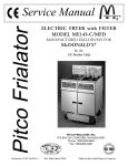
Pitco Frialator
Service Manual
ADVANCED GAS FRYER with FILTER
PITCO MODEL AG14S-C
Literature # L20-172 Rev 1
MANUFACTURED
BY
P.O.BOX 501
CONCORD, NH 03302-0501
PHONE: 1(603)225-6684
for the
CE Market Only
Rev Date 28 February 2001
Made in the United States of America
FOR YOUR SAFETY:
Do not store gasoline or other flammable
vapors or liquids in the vicinity of this or
any other appliance.
WARNING
There is an open flame inside the machine. The
unit may get hot enough to set nearby materials on
fire. Keep the area around the unit free from combustibles.
TO THE PURCHASER
POST IN A PROMINENT LOCATION INSTRUCTIONS TO BE FOLLOWED IN THE
EVENT THAT AN OPERATOR SMELLS GAS.
OBTAIN THIS INFORMATION FROM YOUR
LOCAL GAS SUPPLIER.
WARNING
Ensure that the machine can get enough air to keep
the flame burning correctly. If the flame is starved
of air it can give off a dangerous carbon monoxide
gas. Carbon Monoxide is a clear odorless gas that
can cause suffocation.
WARNING:
IMPROPER INSTALLATION, ADJUSTMENT,
ALTERATION, SERVICE OR MAINTENANCE
CAN CAUSE PROPERTY DAMAGE, INJURY
OR DEATH. READ THE INSTALLATION, OPERATING AND MAINTENANCE MANUALS
THOROUGHLY BEFORE INSTALLING OR
SERVICING THIS EQUIPMENT.
WARNING
Carbon Monoxide gas can build up if you obstruct
the flue. Blocking the flue will also cause the unit
to overheat. DO NOT obstruct the flow of combustion/ventilation or air opening around the machine. Ensure that you meet the minimum clearances specified in the installation instructions.
Adequate clearance around the unit is necessary
for servicing and proper burner operation.
WARNING
This appliance is equipped with a grounding plug.
This is for your protection against shock hazard in
the event of equipment malfunction. Always plug
the unit into a properly grounded receptacle. DO
NOT cut or remove the grounding prong.
WARNING
DO NOT use an open flame to check for gas leaks!
Keep all open flames away from the machine at
all times.
WARNING
Machines equipped with casters and a flexible
power cord, must be connected to a gas supply
with a Quick-Disconnect device. This quick disconnect must comply with all local and national
codes. To limit the movement of the unit without
depending on the connector or quick disconnect,
a restraining device must also be installed.
WARNING
DO NOT supply the fryer with a gas that is not identified on the data plate, located on the inside of one
of the doors of the machine. If you need to convert
the machine to another type of fuel, contact your
dealer or Authorized Service Agency.
WARNING
If the machine should shut down unexpectedly wait
5 minutes before attempting to restart it. This will
allow for any excess gas in the unit to dissipate.
WARNING
The power supply must be disconnected before
servicing or cleaning the unit.
WARNING
To prevent tipping of the machine and splashing of
HOT oil your Pitco Frialator fryer is equipped with
a Gas Hose Quick Disconnect and restraining device. This attaches the rear of the machine to the
wall. When the fryer is in its operating location, lock
the casters and reattach the restraining device to
the rear of the machine.
WARNING
Shortening, when it is at cooking temperatures, is
very HOT and DANGEROUS! Use extreme caution when handling! Use the proper protective gear
such as insulated gloves, aprons, face shield and
sleeves when handling hot shortening. DO NOT
attempt to move any machine that has hot oil in it.
Allow the oil to cool to room temperature or drain
the oil into a suitable container before moving the
fryer.
Table of Contents
Table of Contents ....................................................................................................... i
Chapter 1: HOW DOES IT WORK? ......................................................................... 1
Heating System - Full Tank ..................................................................................... 1
Heating System - Split Tank .................................................................................... 1
Hi - Limit System ..................................................................................................... 2
Filter System ............................................................................................................ 2
Chapter 2: COMPONENT TROUBLESHOOTING .......................................................... 3
Probe ....................................................................................................................... 3
Relays ...................................................................................................................... 3
Hi Limits .................................................................................................................. 3
Drain Valve & Return Valve Switches .................................................................... 3
Transformer ............................................................................................................. 3
Blower ..................................................................................................................... 4
Pressure Switch ....................................................................................................... 4
Gas Valve ................................................................................................................. 4
A note on excessive air velocities within hood systems .......................................... 4
Chapter 3: TROUBLESHOOTING GUIDE ....................................................................... 5
Fryers ....................................................................................................................... 5
Filters ....................................................................................................................... 6
Chapter 4: COMPONENT CHANGEOUT ........................................................................ 7
Probes ...................................................................................................................... 7
Hi Limits .................................................................................................................. 7
Computers ............................................................................................................... 7
Components mounted in the front panel .................................................................. 8
Filter Relays ............................................................................................................. 8
Control Relays ......................................................................................................... 8
Filter Pumps ............................................................................................................. 8
Circuit Breaker ........................................................................................................ 8
Gas Valves ............................................................................................................... 9
Burners and Spark Ignitors ...................................................................................... 9
Proximity Switches .................................................................................................. 9
Blowers .................................................................................................................... 10
Pressure Switches ................................................................................................... 10
Fry Tanks ................................................................................................................. 11
Chapter 5: Parts .................................................................................................................... 13
Operational Components ......................................................................................... 13
Filter ......................................................................................................................... 13
Miscellaneous .......................................................................................................... 13
Wiring Harnesses ..................................................................................................... 14
Chapter 6: Parts Identification .............................................................................................. 15
Chapter 7: Schematics .......................................................................................................... 16 - 17
i
ii
seconds and then check for a flame sense signal
from the Flame Rod. If the Ignition Control Module does not see a flame sense signal it will "Lock
Out".
Chapter 1: HOW DOES IT WORK?
The McDonald's Gas fryer will have certain reactions to what is happening, knowing what these reactions are and knowing what the machine is trying to
do will enable us to diagnose most of the problems Heating System - Split Tank:
likely to be encountered.
· Power to the machine is turned ON:
Heating System - Full Tank:
· The computer is supplied with 24 VAC and, if
the Drain Valve Handle is closed, the Proximity
· Power to the machine is turned ON:
Switch will supply 24 VAC to the DVI (Drain
· The computer is supplied with 24 VAC and, if
Valve Interlock) Input at the computer. The Ignithe Drain Valve Handle is closed, the Proximity
tion Control Modules are also supplied with 24
Switch will supply 24 VAC to the DVI (Drain
VAC at the 24 V terminal.
Valve Interlock) Input at the computer. The Igni- · Computer calls for heat and supplies 24 VDC to
tion Control Modules are also supplied with 24
the Heat Demand Relay which will energize supVAC at the 24V terminal.
plying the Blower Relay and the Pressure Switch
with power. When the Blower Relay energizes
· The computer is turned ON the Blower will be supplied with power and will
· Computer calls for heat and supplies 24 VDC to
increase in speed until the pressure switch closes.
the Heat Demand Relay which will energize sup- · Before the pressure Switch closes it will supply
plying the Blower, the Pilot Solenoid on the Gas
power to the Check Blower Relay which will
Valve and the Pressure Switch with Power.
remain energized.
· The Pressure Switch will energize the Check · When the Pressure Switch comes up to speed it
Blower Relay which will stay energized.
will supply power to the second set of switch
· When the Blower reaches its normal speed it will
points on the Check Blower Relay. Because the
cause the pressure switch to close supplying 24
Check Blower Relay is energized the Blower OK
VAC to the second set of switch points on the
Relay coil will be supplied with power causing
Check Blower Relay. Because the Check Blower
it to energize. When the Blower OK Relay enerRelay is still energized the power will be supgizes, one set of its Switch points supplies voltplied to the TH terminal of each Ignition Control
age to the Left Hand Ignition Control Module at
Module.
the TH terminal and the other set of switch points
· Both Ignition Control Modules supply power to
supplies the right hand Ignition Control Module
the Spark Ignitors. At the same time one of the
with power at the TH terminal. The same power
Ignition Control Modules supplies power to the
that is supplied to the TH terminals of the IgniMain Valve Relay coil. The other Ignition Contion Control Modules is also supplied to the Hi
trol Module supplies power to the switch points
Limit switches which, if closed, will supply
of the Main Valve Relay.
power to the Pilot Solenoid of the Gas Valve.
· The Main Valve Relay energizes allowing the sec- · When an Ignition Control Module is supplied with
ond Ignition Control Module to supply power to
power at the TH terminal it will supply power to
the Main Solenoid of the Gas Valve.
the Ignitor, the Main Solenoid of the Gas Valve
· At this point the main burners will ignite. This
and the Heat Feedback Input of the Computer. (It
will also supply the computer with a heat feedis the lack of this Feedback signal that causes the
back signal. (It is the lack of this Feedback sigComputer to display "Ignition Failure".)
nal that causes the Computer to display "Ignition · The Ignition Control Module will continue to
Failure".)
spark for 10 seconds and then look for a flame
· Each Ignition Control Module will spark for 10
sense signal from the Flame Rod. If the Ignition
1
Control Module does not see a flame sense signal it will "Lock Out".
Hi - Limit System:
When the Hi Limit trips it causes the power to the
Pilot Solenoid to stop and gas will cease to flow
through the gas valve. This will cause a Lock Out
condition. The Hi Limit is an automatic reset type
switch. In order to make the computer recognize that
the Hi Limit has reset it must be turned OFF. The
reset switch must be pressed and released in order
to reset the Ignition Control Modules and the computer turned back ON again for further use of the fryer.
Filter System:
Opening the RED Return Valve Handle will cause
the Pump On Relay to be energized and the pump
will begin to pump. Closing the Return Valve Handle
will de - energize the Relay and the Pump will stop
pumping.
2
Relays:
Chapter 2: COMPONENT
TROUBLESHOOTING:
The Heat Demand relays are 24VDC relays and will
energize when the correct voltage is supplied to the
coil. When energizing, the relay Switching Contacts
will close, thus connecting the Common and Normally Open terminals. The Hi - Limit relay is a
24VAC relay and may be checked in the same manner as the above relay.
Probe:
The resistance of the probe will change as the temperature changes. The resistance will decrease as the
temperature rises. The lower the temperature the
greater the resistance change will be per degree of
temperature change, as the temperature approaches
the working range of the probe, the resistance change
will become more linear.
If the probe is suspect, check its resistance and the
oil/air temperature at which it was taken. Compare
these values on the chart below.
TEMP RESISTANCE
Hi Limits:
A Hi - Limit switch is a normally closed switch until
the temperature at the probe reaches 435ºF ± 15°
(225ºC ± 15º). In order to test this switch it will be
necessary to bypass the Heat Demand Relay. Follow
the Hi Limit testing procedure outlined in the Operating Manual.
TEMP RESISTANCE
ºF
Ohms !
ºF
Ohms !
60
80
100
120
140
160
180
200
210
220
240
260
280
300
320
325
139055 !
84644 !
53146 !
34328 !
22755 !
15446 !
10716 !
7586 !
6427 !
5470 !
4013 !
2991 !
2262 !
1734 !
1347 !
1267 !
330
335
340
345
350
355
360
365
370
375
380
385
390
395
400
1192 !
1123 !
1058 !
998 !
942 !
890 !
841 !
795 !
752 !
712 !
675 !
640 !
607 !
576 !
547 !
WARNING
Do NOT leave the machine during this test. This
test will cause the oil to heat past the normal operating temperature and can cause damage to the machine and its operator.
If the switch does not trip between the prescribed
limits it is defective and should be replaced. Once
tripped, the switch will not reset until the oil has
cooled to approximately 400°F (204ºC). If the switch
does not reset it is defective.
Drain Valve & Return Valve Switches:
This switch is a magnetically operated Reed switch.
When the Drain Valve handle is moved to the open
position, the Actuator will move away from the switch
causing the Reed switch to open. When the Drain
Valve is closed the Reed switch will close. This
switch can also be checked with an Ohm meter. The
normal gap between the Actuator and the Sensor
switch on the Drain Valve handle is 1/8" - 1/4" (3 - 6
mm).
If the probe returns an open circuit or 0 Ohms reading it should be replaced. If the resistance varies more
than 20 Ohms from the above chart when being
checked between 325-375°F (162ºC - 190ºC) the
probe will give a false temperature reading on the
computer and should be replaced. However, it will
continue to operate at a slightly higher or lower temperature. Allow the oil to cool and check the probe Transformer:
resistance at a lower temperature. As can be seen
from the chart a greater degree of offset can be al- Transformers are multiple input voltage, 24 volt output voltage and can be checked by reading the input
lowed at a lower temperature.
and output voltages.
3
Blower:
Check the voltage between the wires going to the
Blower. If voltage is found and the Blower is NOT
turning it is defective.
Pressure Switch:
As the blower speed rises the amount of vacuum on
the suction side of the pressure switch rises past approximately 1.3" WC (0.325 kPa) the Presssure
Switch will close. When the vacuum falls below approximately 0.8" WC (0.2 kPa) the Pressure Switch
will open. With the Blower running, check the IN
and OUT voltage of the Switch. If 24VAC can be
found on one side but NOT the other the Pressure
Switch is defective.
Gas Valve:
The Knob should be in the ON position. Check for
24VAC between the terminals marked MV and MV/
PV and between PV and MV/PV. If voltage IS found
between both of these connections and the Gas Valve
does not open the Gas Valve is defective. If voltage
is NOT present at both of the coils on the Gas Valve,
troubleshoot and repair the machine until voltage IS
present at both coils, retest the Gas Valve as previously described.
A note on Excessive Air Velocities within Hood
systems:
Extended recovery times and flame outage problems
may occur if Hood Air Velocities are excessively
high.
The baffle should be installed in the position shown
in the picture, using two self drilling screws.
4
Chapter 3: TROUBLESHOOTING GUIDE
Fryers:
It is assumed that, before starting any troubleshooting, the power is turned on and the gas lines are connected
correctly.
PROBLEM
PROBABLE CAUSE
CORRECTIVE ACTION
Computer does not come on
nothing shows in either display
A. Main circuit breaker is turned off
B. Fryer fuse is blown
C. Transformer
A. Locate the correct circuit breaker and
turn OFF and back ON again.
B. Check and Replace as needed
C. Check Transformer
Computer heat light comes on
but burners do not heat
A
If the oil is hot the Hi Limit may be
tripped
A. Allow the oil to cool, the Hi Limit will
reset when the temperature falls. Turn
the computer OFF and back ON again.
Press the reset switch.
Heat Light ON, burners not
lit.
A.
B.
C.
D.
E.
F.
G.
H.
Heat Demand Relay
F2 Fuse may be blown
Blower
Pressure Switch
Gas Valve
Ignition Module (One or both)
Gas Valve Relay (Full Tank Only)
Tripped or defective Hi Limit
A.
B.
C.
D.
E.
F.
G.
H.
No Spark heard, blower IS
running
A. Heat Demand Relay
B. Ignition Control Module
C. Spark Ignitor
A. Check and replace where needed.
B. Check and replace where needed.
C. Check and replace where needed.
Spark sound can be heard,
Blower NOT running
A. F2 fuse blown
B. Blower
C. Heat Demand Relay
A. Check and replace where needed.
B. Check and replace where needed.
C. Check and replace where needed.
Spark sound can be heard,
Blower IS running but main
burners do not run
A.
B.
C.
D.
E.
A.
B.
C.
D.
E.
Burner comes ON for short
time, does not come back on
A. Flame Sensor
B. Ignition Control Module
C. Gas Valve
Ignition Control Module
Gas Valve Relay (Full Tank Only)
Bad Pressure Switch
Tripped or defective Hi limit
Gas Valve
5
Check Heat Demand Relay.
Check and replace as needed.
Check and replace as needed.
Check and replace as needed.
Check and replace as needed.
Check and replace as needed.
Check and replace as needed.
Allow the oil to cool, the Hi Limit will
reset when the temperature falls. Turn
the computer OFF and back ON again
to reset the computer. Press the reset
switch. Check and replace is needed.
Check and replace where needed.
Check and replace where needed.
Check and replace where needed.
Check and replace where needed.
Check and replace where needed.
A. Check and replace where needed.
B. Check and replace where needed.
C. Check and replace where needed.
Filters:
PROBLEM
PROBABLE CAUSE
CORRECTIVE ACTION
Red Return Valve is open but no
pump sound can be heard
A. Red Return Valve NOT fully open
B. Filter Circuit Breaker may be tripped
C. Filter Motor Thermal Overload may
be tripped
D. Sensor switch may be loose or bad
A. Pull slightly on the Red handle to check
that it is fully open.
B. Locate the circuit breaker and reset.
C. Push Red reset button located on end
of filter motor.
D. Check that the switch is tight in its
mounting. If switch is bad replace it.
Drain valve is closed and the
computer has been reset but
still shows "DRAINING" or
"TURN OFF"
A. Green Drain Valve is NOT fully
Closed
B. Sensor switch may be loose or bad
A. Apply a little more pressure to the
Green Handle to check that it is
fully closed.
B. Check that the switch is tight in its
mounting. If switch is bad replace it.
Drain Valve is OPEN, the oil
is draining slowly or not at all.
A. Green Drain Valve is NOT fully open
B. Drain is plugged with debris
A. Apply a little more pressure to the
Green Handle to check that it is fully
closed.
B. Use the Clean Out Rod from inside the
Fry Tank to clear the Drain Valve. If this
NOT clear the blockage, CLOSE the
Green Drain Valve and follow these
instructions for clearing the main drain
line.
CAUTION:
Some HOT oil may still come out when
the cap is removed.
Remove the two screw from the end
cap (Do NOT lose these.) Use the
Clean Out Rod to clear the main drain
tube. Install the end cap along with its
gasket and two screws. Do not
overtighten these screws.
6
Chapter 4: COMPONENT CHANGEOUT:
Computers:
It is assumed that for all (except ehere noted) of these
component changeout instructions the fryer has been
shut down and disconnected from the power and gas
supplies, cooled and drained of oil.
CAUTION
Take care not to drop any of the components from
the front panel as this will damage them.
Probes:
1. Remove the two screws from the upper mount of
the front panel.
1. Unplug the wiring connector.
2. Unscrew the small nut on the probe seal.
3. Slide the probe from the seal.
2. Unplug the wiring connector at the rear of the
computer.
NOTE: On split tank machinesyou will find 2 wiring connectors to unplug.
Install in the reverse order using the new ferrule supplied with the new probe.
Hi Limits:
1. Unplug the wiring connector.
Install in the reveres order.
2. Unscrew the Hi Limit from the front of the fry
tank.
Install in the reveres order.
7
Components mounted in the front panel:
To access all of the components mounted in the front
panel follow the instructions below:
7
8
5
Common
3
1. Remove the computer as described in the above
instructions.
The components within the front panel area can
now be accessed.
Coil Terminals
1
NO (Normally Open)
NC (Normally Closed)
Filter Pumps:
Filter Relays:
1. From the front of the machine, loosen and remove
the fittings at the end of each of the flex lines.
2. Remove the 2 bolts, and the front of the Pump/
Motor assembly will drop. The assembly can be
removed from the machine by lifting the rear
slightly and pushing back. The front of the mount
can be lowered until the assembly can be removed
from the machine.
These relays are always wired in the following manner -
Control Relays:
Install in the reverse order.
Circuit Breaker:
1. Remove the 2 mounting
screws on either side of
the door magnet catch. Remove the door magnet
catch.
2. Remove the 2 mounting
screws from the top and
bottom of the cover.
3.
Depress the 4 catches that
Control relays are always wired in the following manhold the circuit breaker in
ner the cover.
8
1. Unscrew the fitting for the gas supply tubing on
the bottom of the burner.
2. Unplug the wire to the spark ignitor.
3. Remove the 2 screws that hold the spark ignitor
and burner in place.
Install of the reverse order.
Gas Valves:
1. Unscrew the fittings to the gas outlet tubes at the
top of the gas valve.
The burner and spark ignitor may be removed together. Install in the reverse order.
2. Unscrew the pipe union, located behind the gas
valve.
Proximity Switches:
3. Unplug the 3 wires that plug into the gas valve.
1. The actuator can be removed by removing the 2
mounting screws.
Install in the reverse order.
Burners and Spark Ignitors:
2. The sensor may be removed by disconnecting the
wiring harness and by removing the 2 mounting
NOTE: If the ignitor is to be removed without the
screws.
burner start the proceedure at step 2.
9
Install in the reverse order.
Blowers:
1. Unplug the wiring connector.
2. Remove the 3 screws from the mounting flange.
3. Remove the 2 screws from the mounting bracket.
Install in the reverse order.
3. Using a flat screwdriver, break the seal at the
motor flange.
4. The motor can now be lowered out of the machine.
NOTE: The new blower will be shipped with the
blower housing attached. Remove the motor from the
blower housing in the above manner. Clean the sealant from the new motor and the old housing (still attached to the machine). Apply a small amount of high
temperature silicone sealant to the motor mounting
flange.
Install the motor in the reverse order of removal.
Pressure Switches:
1. Unscrew the plastic fitting from the air connection on the pressure switch.
2. Unplug the 2 wires from the switch.
10
Fry Tanks:
Full Tanks1. Remove ALL of the computer/controllers from
the machine.
2. Remove the burners and ignitors from the tank to
be removed.
3. Disconnect the drain valve switch wires.
4. Disconnect the return valve switch wires.
5. Disconnect the blower wires.
6. Remove the drain line from the left and right ends
10. Remove all of the screws holding the front of
of the drain valve tee.
the tank.
7. Remove the 3 screws from the front of each unit.
11. Remove the brackets located inside the splash
back.
8. Remove all of the nuts and washers holding the
splash deck in place.
9. Remove the front deck from the machine.
12. Remove the upper rear cover.
11
Split tanksSplit tanks should be removed and installed as pairs in
the same manner as Full Tanks. There are 3 sets of clamps
that hold the two Split Tanks together:
1. On the rear of the tank.
2. On the bottom of the tank accessed by first removing the blower.
3. On the bottom of the tank at the front.
NOTE: To disconnect the filter return piping (as in
step # 15) unscrew the union connecting the return
piping to the tanks.
13. Remove the complete splash back assembly.
Install in the reverse order.
14. Remove the lower rear back cover.
15. Unscrew the compression fitting at the rear of
the tank.
16 Remove the air tube from the air box (the blower
is mounted to this box).
17. Grasp the tank by the middle tube and remove it
from the rear of the cabinet.
12
ENGLISH
PARTS SECTION
13
AG14 FRYER FRONT
PARTS LISTS
I.D. #
PART #
PART DESCRIPTION
1 ...................................................... PP10752 ....................................... 10-32 X 1/2” SCREW
2 ...................................................... A1830901 ...................................... MAGNET STRIKER PLATE
........................................................ A1835001 ...................................... MAGNET STRIKER PLATE COVER
3 ...................................................... A1837501 ...................................... SWITCH MOUNTING PLATE
4 ...................................................... A3802901 ...................................... TOP RIGHT & LEFT DOOR HINGE
5 ...................................................... B3801301-C .................................. DOOR HINGE PIN
6 ...................................................... A3802903 ...................................... BOTTOM RIGHT & LEFT DOOR HINGE
7 ...................................................... B2302301-C .................................. LEFT DOOR ASSEMBLY
8 ...................................................... B2302302-C .................................. RIGHT DOOR ASSEMBLY
9 ...................................................... B3626801-C .................................. FRONT PANEL BEZLE ASSEMBLY
10 .................................................... P0092300 ....................................... 10-24 HEX NUT
11 .................................................... P0080601 ....................................... #10 FLAT WASHER
12 .................................................... PP11370 ........................................ I-12 3600 COMPUTER SINGLE TANK
PP11372 ........................................ I-12 3600 DUAL COMPUTER SPLIT TANK
PP11306 ........................................ 3300 DIGITAL CONTROLLER FULL TANK
PP11307 ........................................ 3300 DIGITAL CONTROL LER SPLIT TANK
13 .................................................... B362601-C ................................... CONTROLLER MOUNTING BEZLE
14 .................................................... PP11068 ........................................ HEAT DEMAND RELAY
P5046688 ...................................... MAIN GAS VALVE RELAY
15 .................................................... A5059102 ...................................... TERMINAL STRIP COVER
16 .................................................... P5045282 ....................................... WIRE TERMINAL STRIP
17 .................................................... PP11058 ......................................... FILTER PUMP RELAY
18 .................................................... PP10429 ....................................... TRANSFORMER CE
PP10210 ....................................... TRANSFORMER DOMESTIC
19 .................................................... PP11225 ......................................... SPARK IGNITION MODULE DOMESTIC
PP11145 ........................................ SPARK IGNITION MODUL E CE
14
15
AG14 FRYER CABINET
PARTS LISTS
I.D. #
PART #
PART DESCRIPTION
1 ...................................................... B4101601-C ................................. SINGLE FRYER BACK SPLASH
B4101001-C .................................. DUAL FRYER BACK SPLASH
B4101101-C .................................. TRIPLE FRYER BACK SPLASH
B4101201-C .................................. QUAD FRYER BACK SPLASH
B4101701-C .................................. QUINT FRYER BACK SPLASH
2 ...................................................... PP10752 ....................................... 10-32 X 1/2” SCREW
3 ...................................................... A1623901 ...................................... REAR CABINET ACCESS PLATE (STEEL)
A1623902 ...................................... REAR CABINET ACCESS P LATE (SS)
4 ...................................................... A1623501+A1623502 .................. SINGLE FRYER CABINET BACK
A1623601+A1623502 .................. DUAL FRYER CABINET BACK
(1st #galvinized, 2nd # stainless)
A1623701+A1623702 ................... TRIPLE FRYER CABINET BACK
A1623801+A1623802 ................... TRIPLE FRYER CABINET BACK TOP
USE DUAL TWICE ........................ QUAD FRYER CABINET BACK
USE DUAL & TRIPLE ................... QUINT FRYER CABINET BACK
5 ...................................................... P0020600 ...................................... 1/4” X 5/8” BOLT
6 ...................................................... PP10815 ....................................... 9” LOCKING CASTER
6 ...................................................... PP10814 ....................................... 9” NON-LOCKING CASTER
7 ...................................................... P0093300 ...................................... 1/4” X 20 NUT
8 ...................................................... B3622401-C ................................. SINGLE FRONT PANEL TOP DECK
B3627001-C .................................. DUAL FRONT PANEL TOP DECK
B3627201-C .................................. TRIPLE FRONT PANEL TOP DECK
B3627401-C .................................. QUAD FRONT PANEL TOP DECK
B3628201-C .................................. QUINT FRONT PANEL TOP DECK
9 ...................................................... P0080650 ...................................... 1/4” FLAT WASHER
10 .................................................... P0093300 ...................................... 1/4” X 20 NUT
11 .................................................... A1838101 ...................................... SINGLE CABINET BOTTOM PLATE
A1834501 ...................................... CABINET BOTTOM PLATE LEFT HAND
(Non-filter) .......... A1839301 ...................................... DUAL CABINET BOTTOM PLATE
(Non filter) .......... A1839303 ...................................... TRIPLE CABINET BOTTOM
(Filter) ................. A1839401 ...................................... TRIPLE CABINET BOTTOM RIGHT H.
A1839501 ...................................... PUMP BOTTOM COVER
16
17
AG14 FRYER FILTER
PARTS LISTS
I.D. #
PART #
PART DESCRIPTION
1 ...................................................... B4003203-C ................................. OIL RETURN HANDLE FULL & RH SPLIT
B4003204-C .................................. OIL RETURN HANDLE LH SPLIT
2 ...................................................... P0079500 ....................................... 10-24 X 1/2” SCREW
3 ...................................................... A7004401 ...................................... DRAIN LINE CLEAN OUT COVER
4 ...................................................... PP11182 ......................................... CLEAN OUT COVER GASKET
5 ...................................................... PP10568 ......................................... 10-24 WING NUT
6 ...................................................... B6643101-C .................................. FILTER DRAIN LINE END CAP
7 ...................................................... PP11181 ......................................... DRAIN LINE END CAP GASKET
8 ...................................................... PP10696 ......................................... 10-24 X 1/2” SCREW
9 ...................................................... PP11241 ......................................... FLEX TUBING WITH FITTINGS 18”
10 .................................................... B6638601-C .................................. PUMP & MOTOR ASSEMBLY 115VAC
(Including tubing & heat tape) ... B6638602-C .................................. PUMP & MOTOR ASSEMBLY 240VAC
(Including tubing & heat tape) ... B6638603-C .................................. PUMP & MOTOR ASSEMBLY 220VAC
(Pump & motor only) ...... PP10101 ......................................... PUMP & MOTOR ASSEMBLY 115-230VAC
PP10416 ........................................ MOTOR ONLY 115-230VAC
(Pump & motor only) ...... PP10171 ......................................... PUMP AND MOTOR ASSEMBLY
PP10417 ........................................ PUMP ONLY
11 .................................................... PP11242 ......................................... FLEX TUBING WITH FITTINGS 20”
12 .................................................... P0020600 ....................................... 1/4-20 X 5/8 BOLT
13 .................................................... P0080650 ....................................... 1/4 FLAT WASHER
14 .................................................... B6652601-C .................................. FILTER RETURN RECEPTICLE ASSY.
15 .................................................... PP10039 ......................................... HEAT TAPE 165 WATT 110VAC 79”
PP10080 ........................................ HEAT TAPE 165 WATT 240VAC 79”
PP10194 ........................................ HEAT TAPE 96 WATT 110VAC 48”
PP10598 ........................................ HEAT TAPE 96 WATT 240VAC 48”
18
19
AG14 FRYER FILTER DRAWER
PARTS LISTS
I.D. #
PART #
PART DESCRIPTION
1 ...................................................... B6640901-C .................................. PAPER RETAINING RACK
2 ...................................................... B6647701-C .................................. OIL DRAIN CATCH TOWER
3 ...................................................... PP10409 ....................................... FILTER COUPLING “O” RING
4 ............................................................................................................... FILTER PICK-UP ASSEMBLY
5 ...................................................... P0020900 ...................................... 1/4-20 HEX HEAD SCREW
P6071020 ....................................... 1/4” NYLON BUSHING
P0080650 ....................................... 1/4” FLAT WASHER
P0093300 ....................................... 1/4-20 NUT
6 ...................................................... PP10177 ....................................... VINYL PROTECTIVE COVER
P0093300 ....................................... 1/4-20 NUT
P0080650 ....................................... 1/4” FLAT WASHER
P0020900 ....................................... 1/4-20 HEX HEAD SCREW
7 ...................................................... B6640701-C ................................. FILTER DRAWER HANDLE
8 ...................................................... B6640601-C ................................. FILTER DRAWER WELDMENT
9 ...................................................... PP11152 ........................................ ROLLER WHEEL KIT
10 .................................................... B6656801-C ................................. FILTER DRAWER EXTENSION RAIL (RH)
B6656802-C .................................. FILTER DRAWER EXTENSION RAIL (LH)
11 .................................................... A7008302 ...................................... PAPER SUPPORT RACK
12 .................................................... B6661501-C ................................. FILTER PAN
13 .................................................... P0007300 ...................................... 8-32 X 1/4” SCREW
14 .................................................... PP10900 ....................................... FLAT WASHER
15 .................................................... B6641001-C ................................. FRONT FILTER PAN COVER W/HANDLE
A7001102 ....................................... FRONT FILTER PAN COVER NO HANDLE
16 .................................................... P6071516 ...................................... FILTER PAN COVER HANDLE
17 .................................................... A7013502 ...................................... REAR FILTER PAN COVER
18 ............................................................................................................. CRUMB CATCH BASKET
20
21
AG14 FRYER DRAIN VALVE HANDLE
PARTS ASSEMBLY
I.D. #
PART #
PART DESCRIPTION
1 ...................................................... PP11302 ........................................ VINYL DRAIN VALVE HANDLE COVER
2 ...................................................... PP10263 ......................................... DRAIN PROXIMITY SWITCH ACTUATOR
3 ...................................................... B4002902-C .................................. DRAIN VALVE HANDLE FULL, RH SPLIT
B4002901-C .................................. DRAIN VALVE HANDLE LH SPLIT VAT
4 ...................................................... PP10266 ......................................... 4-40 X 1/4” SCREW
5 ...................................................... PP10647 ......................................... 1/2-13 NUT
6 ...................................................... PP11059 ......................................... PLUNGER ASSEMBLY
7 ...................................................... A4015801 ...................................... DRAIN HANDLE RELEASE LEVER
8 ...................................................... PP11303 ......................................... RELEASE LEVER VINYL COVER
9 ...................................................... B4003001-C ................................. FULL TANK HANDLE ASSEMBLY
(Complete drain valve handle assy) B4003003-C ................................. LH SPLIT TANK HANDLE ASSEMBLY
B4003005-C ................................... RH SPLIT TANK HANDLE ASSEMBLY
22
23
AG14 GAS & BURNER SYSTEM
PARTS LISTS
I.D. #
PART #
PART DESCRIPTION
1 ...................................................... B3317701-C ................................. FULL TANK BURNER BOX ASSY.
B3321101-C ................................. FULL TANK BURNER BOX IN SUL. KIT
2 ...................................................... PP11064 ......................................... HI LIMIT SWITCH
3 ...................................................... A8027301 ...................................... IGNITOR MOUNTING BRACKET
4 ...................................................... B8022301-C .................................. BURNER (DOMESTIC)
B8027001-C ................................. BURNER (CE GERMANY)(CE LP)
5 ...................................................... PP11131 ......................................... IGNITOR (DOMESTIC)
PP11193 ........................................ IGNITOR (CE)
6 ...................................................... PP11193 ......................................... FLAME SENSOR (CE)
7 ...................................................... CALL SERVICE AGENT FOR # BURNER ORIFICE
8 ...................................................... B8022001-C ................................. GAS VALVE ASSY. FULL TANK (NAT)
B8022101-C ................................. GAS VALVE ASSY. LH SPLIT TANK (NAT)
B8022103-C ................................. GAS VALVE ASSY. RH SPLIT TANK (NAT)
B8022002-C ................................. GAS VALVE ASSY. FULL TAN K (PROP)
B8022102-C ................................. GAS VALVE ASSY. LH SPLIT TANK (PROP)
B8022104-C ................................. GAS VALVE ASSY. RH SPLIT TANK (PROP)
9 ...................................................... B3316801-C ................................. TEMPERATURE PROBE ASSY.
10 .................................................... B3314801-C ................................. SPLIT TANK BURNER BOX ASSY. LH
B3314802-C ................................. SPLIT TANK BURNER BOX AS SY. RH
B3321201-C ................................. SPLIT TANK BURNER BOX IN SUL. KIT
11 .................................................... B8021602-C ................................. COMBUSTION TUBE (FULL & SPLIT
TANK)
12 .................................................... B3316601-C ................................. SPLIT TANK
13 .................................................... B3316501-C ................................. FULL TANK
24
25
AG14 FRYER ACCESSORIES
PARTS LISTS
I.D. #
PART #
PART DESCRIPTION
1 ...................................................... PP11332 ........................................ FRYER COVER HANDLE
2 ...................................................... P0082400 ...................................... WASHER
3 ...................................................... PP10693 ....................................... SCREW
4 ...................................................... A1103202 ...................................... BASKET HANGER
5 ...................................................... A1907504 ...................................... CHANNEL STRIP INTERIOR OF A SPLIT
6 ...................................................... A1906804 ...................................... CHANNEL STRIP (SPLIT TO SPLIT TANK)
A1906804 ...................................... CHANNEL STRIP (SPLIT TO FULL, FULL
TO FULL TANK)
7 ...................................................... P6073148 ...................................... TUBE RACK (FULL TANK)
B4510401-C ................................. TUBE RACK (SPLIT TANK)
8 ...................................................... B2100904-C ................................. COVER ASSEMBLY (FULL TANK)
B2100903-C ................................. COVER ASSEMBLY (SPLIT TANK)
26
27
28
29
30
31
Should you have any questions about or problems with your equipment, please contact
the Dealer or Parts and Service representative covering you area. Pitco Frialator may be
contacted directly at:
Country Code (603)225-6684
Country Code (603)225-8497 Fax