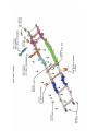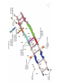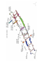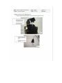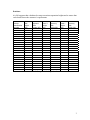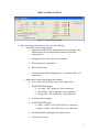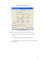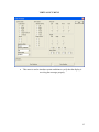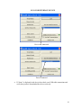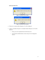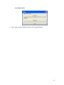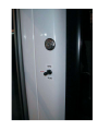
1
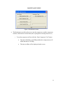
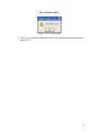
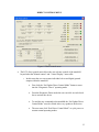
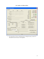
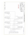
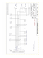
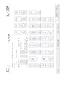
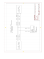
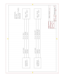
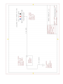
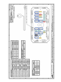
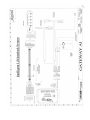
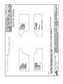
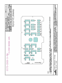
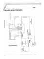
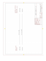
SPIRIT OF MOBILITY SERVICE and PARTS MANUAL SERVICE OPERATIONS Welcome to ARBOC Mobility, LLC. Our Spirit of Mobility bus features premium technology for safety, reliability and ease of operation. We realize that as a Service or Parts professional, you represent your dealership and ultimately, our product. Your understanding of the parts and procedures to maintain our Spirit of Mobility bus is vital to your customer’s satisfaction. We hope that you will find this manual to be an informative and useful reference tool. Our Spirit of Mobility bus is built on the GM 3500/4500 chassis and includes premium components for the most reliable and comfortable travel experience. Because most functions and features are unchanged, the GM service manual should be reviewed in conjunction with this guide for location, proper operation and service of these features. Reference to the GM Service Manual is REQUIRED for specific information on safety practices, cautions and important information such as torque specifications. The information presented in this manual is correct at the time of printing. With our program of ongoing improvement, policies and procedures regarding Parts and Service presented may change or be modified. ARBOC Mobility, LLC reserves the right to make changes without notice. We value your input. Please contact ARBOC Mobility, LLC Service Operations with any questions or suggestions at 1-866-953-5555. OVERVIEW This manual is organized by group numbers. This format allows for easy location of ARBOC Mobility parts and service operations by their main group. Subgroups will further categorize items as our efforts continue. There are eleven (11) groups: 0. Vehicle: 1. Body: Labels, Decals, Manuals Exterior, Interior, Windows 2. Powertrain: Engine and Driveline Related 3. Frame: Bumpers, Tow Hooks 4. Suspension: Front and Rear Suspension, Air Suspension Components, Compressor 5. Exhaust: Pipes. Mufflers, Clamps, Hangers 6. Electrical: Wiring, Switches, Relays 7. Heat: Components, Hoses, Valves 8. Air Conditioning: A/C Components 9. Ramps: Power, Manual 10. Options: Safety kits TABLE OF CONTENTS PARTS SERVICE …………. Group 0 .………… .………… Group 1 ……….… ………… Group 2 .………… .………… Group 3 ……….… …………. Group 4 .………… .………… Group 5 ……….… ………… Group 6 .………… .………… Group 7 ……….… .………… Group 8 ……….… ………… Group 9 .………… .……….. Group 10 ………. VEHICLE SYSTEM 00.00 VEHICLE 00.00-01 LABELS ITEM # ITEM # PART # 1183763 1183764 1183854 1186011 1169637 1199921 1201035 1201039 1183945 1183946 1183387 1183388 1169642 1183389 1183387 1176058 1183762 1169636 378428 378432 DESCRIPTION LABEL, EMERGENCY RELEASE LABEL, KNEELING 6.000 X 2.000 LABEL, EMERGENCY RELEASE PULL LABEL, PATENTS PENDING SOM LABEL, HANDICAP SYMBOL 4 X LABEL, AMSOIL SYNTHETIC LABEL, WARNING SERVICE VEHICLE LABEL, OIL RESERVOIR AMSOIL LABEL, OPEN 2.5" X 1" RED LABEL, CLOSE 2.5" X 1" GREEN LABEL, TO OPERATE RAMP INTERLOCK LABEL, TO OPERATE RAMP 4" LABEL, FOR FAST IDLE 4" X 1 1/4" LABEL, TO STOW RAMP 5.5" X 1.25" LABEL, TO OPERATE RAM INTERLOCK 4" X 1.25 ' LABEL, PRIORITY SEATING FOR PERSONS WITH DISABILITIES LABEL, SEATS ARE NOT INTENDED FOR SEATBELT LABEL, METAL STANDING FORWARD WHT LINE 13"X4-1/4" LABEL, UNLEADED FUEL ONLY LABEL, DIESEL FUEL ONLY 00.00-02 OWNERS MANUALS PART # DESCRIPTION 1200982 HEATER, 65BTU GAS SYSTEM GM SERVICE MANUAL TORQUE LB-FT TORQUE LB-FT SYSTEM 00.00 VEHICLE 00.00-03 DECALS ITEM # PART # 1182292 1182293 1182294 DESCRIPTION TORQUE LB-FT LOGO,SPIRIT OF MOBILITY BY ARBOC 9.1 X 37 BLK/GRY/RED/YE LOGO,SPIRIT OF MOBILITY BY ARBOC 5.4X22.3 BLK/GRY/RED/YE LOGO,SPIRIT OF MOBILITY BY ARBOC .6163 X 6"BLK/GRY/RED/Y BODY SYSTEM 01.00 BODY 01.00-01 EXTERIOR ITEM # PART # DESCRIPTION 01.00-01.1 CAPS 1163764 CAP, FRONT FIBERGLASS PW 1186177 PILLAR, BACK ROADSIDE 1186178 PILLAR, BACK CURBSIDE 1163768 PANEL, CAP PASSENGER ENTRY 1186180 CAP, REAR TOP LIGHT BAR 1185662 PILLAR, PASSENGER SIDE-A 1185660 PILLAR, PASSENGER SIDE-B 1164315 PANEL, ROCKER ODS FIBERGLASS 1163769 PANEL, REAR PASSENGER ENTRY FGL 1163799 PANEL, DRIVER TRANSITION FGL SHELL W/O GLASS 1185659 TRIM, A PILLAR DRIVER SIDE-B 01.00-01.2 MUD FLAP 1200642 MUD FLAP, 19 X 18-1/4 LDPE 01.00-01.3 RUNNING BOARD 1190926 RUNNING BOARD, ALUM - DRIVERS SIDE 01.00-01.4 SPARE TIRE 1117247 SPARE TIRE ASSY 01.00-01.5 WHEELS 1125128 WHEEL LINER. STAINLESS STEEL 1140341 VALVE EXTENSION 5-3/4 SS 1137423 VALVE EXTENSION 125DEGREE SS 1169740 1085462 1085463 455433 1169737 1172601 1179733 1172600 1200269 1186292 1169747 1169742 1200961 1200962 506953 01.00-01.6 LIGHTS TAILLIGHT, 4" CLEAR ROUND LED TAILLIGHT, 4" STOP/TAIL/TURN LED GROMMENT, 4" ROUND FLAT LED LICENSE PLAT ASSY LIGHT, LICENSE PLATE LED LIGHT, CLEARANCE SEALED RED LED SCREW, #8 X 1 SELF TAP STAINLESS STEEL LIGHT, CLEARANCE SEALED RED AMBER BASE, METAL DIE CAST CLEARANCE - ARMOR MARKER LIGHT, CLEARANCE RED LED 1" GROMMET MNT EMERG EGRESS LIGHT, 8" CLEAR OVAL LED SURFACE MOUNT STYLE LIGHT, BRAKE LED RED SURFACE MOUNT STYLE LIGHT, 7" AMBER LED SCHOOL BUS STYLE SIGNAL LIGHT, FLASHER MODULE SCHOOL BUS STYLE REFLECTOR, RED ROUND 2 1/4 TORQUE LB-FT 1169807 1169808 1169805 1169806 1169809 1169810 1191605 01.00-01.7 MIRROR MIRROR, EXT EUROSTYLE DRVS REMOTE HEATED MIRROR, EXT EUROSTYLE PASS REMOTE HEATED MIRROR, EXT EUROSTYLEM715 DVR 4-WAY HAND ADJ NON-HEATED MIRROR, EXT EUROSTYLEM715 PAS 4-WAY HAND ADJ NON-HEATED MIRROR, EXT DRVS REMOTE-FLAT MAN-CONVEX BOTH HTD LED W/SWC MIRROR, EXT PASS REMOTE-FLAT MAN-CONVEX BOTH HTD LED W/SWC WIRE HARNESS, MIRROR TURN SIGNALS 1178274 1163769 1176860 503070 1037710 446887 1042592 01.00-01.8 TRIM TRIM, DOOR EDGE 0.15 SMOOTH LEFT REAR PANEL, REAR PASSENGER ENTRY MLDG, INSER 7/8" VINYL PAINTABLE MARLITE MLDG, INSERT FLAT W-1/8" OFFSET MLD, GUTTER RAIL INSERT ROOF EDGE, NON-INSERT PWW/CURVED LEG GUTTER SPOUT, LEFT & RIGHT POLAR WHITE 1182675 1051038 413104 462866 377288 01.00-01.9 REAR DOOR DOOR,55X33 LAM400-EXT REAR CARGO STRUT, GAS 10LB 14" TAPE, TACKY 3/4 X 1/8 (DOOR /LIGHT SEAL) GIMP, COVE 1/2" WHITE (DOOR SEAL) BRACKET, FLAT 2.5L X 1.44W X .660 BALL STUD 1180882 1180884 1165809 1168851 1169687 1169692 1165927 1165939 1165943 1165929 1165931 1168930 1167767 1165937 1165928 1165941 1165948 1165935 1165946 1180584 1178829 1165926 1165933 1180081 1165945 1165808 1168849 502719 1061400 01.00-01.10 WINDOWS WINDOW, 12W X 30H FLAT SOLID TINT W/GARNISH WINDOW, 17.31 X 27.06H FLAT SOLID TINT W/GARNISH WINDOW, 17.31 X 38-5/8 RAD TINT GARNISH, WND 17-3/4 X 38-5/8 .014 BLACK WINDOW, 19.13 X 36-1/4 RAD FLAT SOLID TNT GARNISH, WND 19.13 X 36-1/4 .014 BLACK WINDOW, 20-3/8 X 36-3/8 DS RAD SLDR GARNISH, WND 20-3/8 X 36-3/8 .014 BLACK WINDOW, 36-3/8 X 36-3/8 RAD SLDR TNT WINDOW, 36-3/8 X 36-3/8 DBL T-SLDR TNT WINDOW, 36-3/8 X 36-3/8 DBL T-SLDR TNT WINDOW, 36-3/8 X 36-3/8 RAD SOLID TNT WINDOW, 36-3/8 X 36-3/8 RAD SOLID TNT EGRESS WINDOW, 36-3/8 X 36-3/8 DBL T-SLDR EGRESS WINDOW, 36-3/8 X 36-3/8 RAD SOLID TNT GARNISH, WND 36-3/8 X 36-3/8 .014 BLACK WINDOW, 45-3/8 X 36-3/8 RAD SOLID TNT WINDOW, 45-3/8 X 36-3/8 DBL T-SLDR OPEN TNT GARNISH, WND 45-3/8 X 36-3/8 .014 BLACK WINDOW, 46.5 X 8.5 CLEAR ACRYLIC FLAT SOLID WINDOW, 46.5 X 8.5 WHITE ACRYLIC FLAT SOLID WINDOW, 60-3/8 X 24-3/8 RAD SOLID TNT BLACK WINDOW, 60-3/8 X 24-3/8 RAD SOLID TNT EGRESS WINDOW, 60-3/8 X 24-3/8 RAD SOLID TNT EGRESS GARNISH, WND 60-3/8 X 24-3/8 .014 BLACK WINDOW, 8 X 35-3/4 RAD TNT FLAT SOLID TRANSITION GARNISH, WND 8 X 35-3/4 .014 BLACK SCREW, #8 X 5/8 PAN HD QUADREX (GARNISH/WINDOW FASTENER) TAPE, PVC .250 X .625 V810 GREY #8 DENSITY (WINDOW SEAL) EGRESS WINDOW LIGHTS 1186292 LIGHT, CLEARANCE RED LED 1" 1168888 1184636 1200975 1061400 01.00-01.11 HATCH HATCH, ROOF STANDARD SAFETY HATCH, ROOF TRANSPEC WHITE HATCH, ROOF W/OUTSIDE RELEASE VENT W/#16 MTG FRAME LT GRAY TAPE, PVC .250"X.625" GREY #8 DENSITY 01.00-01.12 WHEEL WELLS 1200799 FLOOR ASSY, STL CENTER W/STAINLESS STEEL 1163809 FLOOR ASSY, STL CENTER SYSTEM 01.00 BODY 01.00-02 INTERIOR ITEM # PART # DESCRIPTION 01.00-02.1SEATS SEATS - REFER TO FREEDMAN SEATING - 7/16" BOLT SEATS - REFER TO FREEDMAN SEATING - 1/2" BOLT SEATS - REFER TO FREEDMAN SEATING - 3/8" BOLT SEATS - REFER TO FREEDMAN SEATING - DRVS SEAT SEAT BELTS - REFER TO FREEDMAN SEATING ALL FASTENERS (BOLTS.NUTS WASHERS) TO BE GRADE #8 1171752 US ARM, BLACK SOM 1172039 FOOTREST, METAL BLACK SOM 1171769 HEADREST, ADJUSTABLE MIB BACK 1171767 POCKET, MAP MESH SOM 1200768 GRAB RAIL, CITI SEAT 1171765 GRAB HANDLE, CORNER BLACK SOM 1171761 GRAB HANDLE, AV BLACK SOM 1179098 GRAB HANDLE, HIGH BACK AV BLACK SOM 1172042 CHAIR, PILLOW SEAT TOP 1191695 ARM RESTS, UPHOLSTERED RITZ 1171774 BACK, SEAT ABS FEATHER WEIGHT 1190928 SNACK TRAY, FREEDMAN SOM 1190927 CUP HOLDER, FREEDMAN SOM 1184626 1184637 1198736 1169800 1189039 1190539 1200658 1199940 1199862 1199859 1200939 1200316 1200953 1199855 1199858 1198737 1178921 1190907 1178923 TORQUE LB-FT 01.00-02.2 ANCHOR SYS ANCHOR ASSY, FLOOR Q-STRAINT ANCHOR ASSY, FLOOR SURE-LOK TIE DOWN SYSTEM, WHEELCHAIR L TRACK TIE DOWN KIT, WHEELCHAIR L-SERIES W/D-RINGS & S-HOOKS TIE DOWN KIT, WHEELCHAIR W/BELTS MANUAL W-STRAINT SCREW, CAP SOCKET FLAT HEAD 6/16-18 X 1 1/2" UNC 3/16 KEY SHEET STRIPS, 14 GA STL 6"X10' L-TRACK, AL PRE-DRILLED 100" FL REGULAR FLOOR END CAP, "L" TRACK TIE DOWN KIT, W"L" TRACK RETRACT SHOULDER BELT QSTRAINT TIE DOWN KIT, QSTRAINT L TRACK RETRACT SHOULDER BELT TIE DOWN KIT, QSTRAINT QRT810 AT-SC TIE DOWN KIT, SURE-LOCK AUTO LOCKING SOLO RETR W/S HOOKS TIE DOWN KIT, SLIDE N CLICK W/RETRACT SHOULDER BELT WSTRAINT TIE DOWN KIT, SLIDE N CLICK W/ SHOULDER BELT WSTRAINT TIE DOWN SYSTEM, WHEELCHAIR L-TRACK, AL PRE-DRILLED 100" POUCH, WALL STORAGE SEAT BELT VINYL SURLOK POUCH, WALL STORAGE SEAT BELT VINYL QSTRAINT 60 60 15 44 60 1191886 1191698 1199849 1199687 1183017 480659 1178634 1199933 1196671 01.00-02.3 RACKS RACK, OVERHEAD PARCEL 12' GREY DELUXE (4FT SECTIONS) RACK, OVERHEAD PARCEL 12' GREY STANDARD (4FT SECTIONS) PLEXIGLASS, CLEAR 3/16" X 12" X 12" STORAGE RACK, WALKER/CANE 1-1/4" YELLOW RACK, LUGGAGE 1-1/4" SS 48" W/DUAL FLDG SHELVES CARGO LINER, APPL GREY RACK, LUGGAGE 1-1/4" SS 67WX26DX66 W/DUAL FLDG SHELVES STORAGE RACK, WALKER/CANE WHEEL WELL 1-1/4" STORAGE RACK, WALKER/CANE 1-1/4" 1183398 1186183 1173868 1185535 1173884 1164313 1182102 1186181 1199050 1183398 1186427 1199098 1180586 1199077 1199690 1186428 1199100 1200217 1200456 1200457 1199689 1200221 1199079 01.00-02.4 GRAB RAILS PLEXIGLASS, .157 X 15 X 20 W/CUTOUT PANEL, MODESTY PASS PLASTIC STANCHION, DRVS OFFSET 1-1/4 SS 80" LONG LEG GRAB RAIL, OVERHEAD 1-1/4 SS 78" LONG W/MOUNTING GRAB RAIL, ENTRY RH 1-1/4 SS W/MOUNTING BARRIER, ENTRY LH 1-1/4 SS W/GRAB RAIL PADDING, STANCHION 2" OD 1-1/2" PANEL, MODESTY DVRS PLASTIC STANCHION, DRVS OFFSET YELLOW 1-1/4 SS 80" LONG LEG PLEXIGLASS, .157 X 15 X 20 W/CUTOUT BRONZE ACRYLIC GRAB RAIL, OVERHEAD 1-1/4 SS 124.75" GRAB RAIL, OVERHEAD 1-1/4 SS 102" YELLOW GRAB RAIL, OVERHEAD 1-1/4 SS 102" GRAB RAIL, ENTRY YELLOW 1-1/4 RH W/2 OV MTG FLGS 24X24 1/4 GRAB RAIL, OVERHEAD YELLOW 1-1/4 SS 78" GRAB RAIL, OH -1/4 SS 148.5" GRAB RAIL, OVERHEAD YELLOW 1-1/4 SS 148.5" GRAB HANDLE, 1" SS FLATENED W/CUSTOM FLANGES HANDLE, ASSIST ENTRY 1" RH W/CUSTOM FLANGES HANDLE, ASSIST ENTRY 1" LH W/CUSTOM FLANGES GRAB RAIL, OVERHEAD 1-1/4 SS YELLOW 124.75" GRAB HANDLE, 1" SS FLATENED W/CUSTOM FLANGES YELLOW BARRIER, ENTRY YELLOW LH1-1/2 1178262 1176729 1199486 940539 01.00-02.5 INTERIOR COVERINGS AUTOCLOTH, PADDED 3/16 FOAM 54"PERIGON SLATE GREY TRIM, BATTEN 1-1/2 X 8.25 GRANITE AUTOCLOTH, PADDED 3/16 FOAM 54" VENICE NEUTRAL TAN MAT, RIBBED RUBBER 1/8" 1176842 1184792 1174356 1200781 01.00-02.6 MIRRORS MIRROR, INTERIOR 6 X 9 CONVEX BRACKET, MIRROR INTERIOR LENS, FRESNAL 11 X 14 SOM MIRROR, INTERIOR 4 X 16 CONV 406632 01.00-02.7 SPEAKERS SPEAKER, W/GRILL 25 WATT 6OZ 01.00-02.8 COVERS 1183362 HATCH, ACCESS 10 X 18 ABS GREY W/ THUMB LATCH 1167538 1167539 1200646 995693 1182035 1182039 01.00-02.9 ENTRY DOORS PNEUMATIC PANEL, ENTR DR 40" X 76" W/E HEADER, DOOR PNEUMATIC 40" A LABEL, EMERGENCY EXIT RED SEAL, TRIM-LOK 1/16" BLACK D SEAL, EPDM .760 X .930 X25 SEAL, WIPER EPDM .125 X 3.00 1189090 1167538 1167540 1200646 995693 1182035 1182039 ELECTRIC BOM, ENTRY DOOR SEALS SOM PANEL, ENTR DR 40" X 76" W/E HEADER, DOOR ELECTRIC 40" AS LABEL, EMERGENCY EXIT RED SEAL, TRIM-LOK 1/16" BLACK D SEAL, EPDM .760 X .930 X25 SEAL, WIPER EPDM .125 X 3.00 1186625 1186634 1186629 1186194 1174503 1186625 1186187 01.00-02.10 DASH DASH PANEL, ENGLISH ONLY W/RR DR DASH PANEL, BILINGUAL W/RR DR DASH PANEL, BILINGUAL W/O RR DR BASE, CONSOLE MOUNT ABS BLACK DASH PANEL, ENGLISH ONLY W/O RR DR DASH PANEL, ENGLISH ONLY W/ RR DR CONSOLE, DRIVERS BLACK 886293 01.00-02.11 INT TRIM TRIM, BATTEN SNAP 3/16" PLASTIC 1186197 1186176 1185658 1186504 1190411 1186189 01.00-02.12 INT ABS PLASTIC FRONT OH, ABS FLINT PANEL, ENTR DOOR OVERHEAD ABS PILLAR, DRIVER SIDE-B PANEL, ABS AIR EXHAUST SMALL TRIM RING, CONDENSOR 6 X 40 TRIM, FRONT STEP BLACK STEEL STRUCTURE INTERIOR PANELS 1185658 & 1185659 (trim) 1186504 1186197 1186176 1185662 1185660 GRAB HANDLES & STANCHIONS SEATS REAR DOOR POWERTRAIN ITEM # ITEM # PART # 1189314 1189515 1189313 465136 491613 465138 465135 465137 1189315 SYSTEM 02.00 POWERTRAIN 02.00-01 DRIVELINE DESCRIPTION YOKE, TUBE NEAPCO JACKSHAFT BOOT CLAMP, 60.1 TO 68.0 MM MIDSHIP STUB, JACKSHAFT SOM END YOKE ASSY U-JOINT, E-40 STRETCH LOCKING NUT, SPLINE SHAFT CARRIER BEARING BEARING STRAP KIT, 1350 SERI TUBING, 3.5" X .083 X 108" PART # 1167198 1165724 1187766 SYSTEM 02.00 POWERTRAIN 02.00-02 MOTOR MOUNTS DESCRIPTION BRACKET ASSY, ENGINE MOUNT RH BRACKET ASSY, ENGINE MOUNT LH BRACKET ASSY, ENGINE MOUNT LH DIESEL TORQUE LB-FT TORQUE LB-FT FRAME ITEM # ITEM # PART # 1164267 1171990 1165726 1189751 1200148 SYSTEM 03.00 FRAME 03.00-01BUMPER DESCRIPTION TORQUE LB-FT BUMPER, REAR 5MPH PLATE, BOLT ON ANTI-RIDE BUMPER, STEEL 10GA X 95 PC BLACK BUMPER, ENGERY ABSORBING BUMPER, REAR 5MPH W/HAWKEYE BACK UP SENSOR SYSTEM 03.00 FRAME 03.00-02 TOW HOOK PART # DESCRIPTION 1198637 TOW HOOK, 10,000# BLACK 5.38 X 1.25 X 3.25 TORQUE LB-FT 100 SUSPENSION SYSTEM SUSPENSION JJL A644C 85817 11 12 13 14 15 16 17 18 19 20 DESCRIPTION SWAY BAR, FRT SUSPENSION AIR BAG, FRONT 8.6" DIA SPRING BRACKET, STL SHOCK UPPER LH BRACKET, STL SHOCK UPPER RH BALL JOINT, LOWER SOM GM #88982337 BRACKET, SPRING SEAT FRT UPPER SHOCK ABSORBER, FRONT ASSY BRACKET, SPRING SEAT FRT LOWER CONTROL ARM, LOWER RH SOM CONTROL ARM, LOWER LH SOM BOLT, 3/8-16X51/2 SWAY BAR NUT, 3/8-16 NUT, BALL JOINT PIA OF GM # 88982337 1172608 BOLT, 5/8-11X5 SHOCK UPPER 1169635 WASHER, 5/8 FLAT 80933 NUT, 5/8-11 A719 BOLT, 3/4-10X3 SHOCK LOWER 88442 WASHER, 3/4 FLAT SWAY BAR BUSHING PAC RE-USE GM 117326 FRONT SENSOR ASSY PIA OF HADLEY PART # 1164291 1167220 1167208 1173237 1171614 1170738 1198729 1170739 1170383 1170384 ITEM # 1 2 3 4 5 6 7 8 9 10 SYSTEM 04.00 SUSPENSION 04.00-02 FRONT SUSPENSION 145 74 110 TIGHTEN TILL RUBBER BUSHING IS SEATED TORQUE LB-FT 10/30/2009 SYSTEM SUSPENSION JJL ITEM # 6 3 4 14 11 32 37 38 36 43 44 17 34 42 16 18 33 22 35 24 40 35 24 8 39 13 23 7 39 13 23 9 12 10 19 20 21 27 25 26 41 29 25 28 30 25 28 2 1 31 1171503 88441 1169639 1171515 88441 1169639 1179450 88441 1169639 80933 1179451 88441 1169639 80933 1179453 59760 59770 1165737 723 80934 1194868 A 693 59769 692 1194880 A 693 59769 1199499 A 693 59769 1190176 1173238 1170766 1182078 1170657 PART # 1173239 86397 85820 1165730 325 1165741 83507A 98271 DESCRIPTION BAR , STEEL AIR BAG SUPPORT BOLT, FLANGE 1/2-13 X 1 1/4 LOCK NUT, FLANGE 1/2-13 U-BOLT 5/8-18 LOCK NUT, NYLON 5/8-18 SHOCK ABSORBER, REAR BOLT, 14MM- 2-2.0-80 (TOP OF SHOCK) WASHER, FLAT 14MM NUT, LOCK 14MM-2.2 BOLT, FLANGE 14MM -2.2 (RE-USE GM BOTTOM OF SHOCK) NUT, FLANGE 14MM 2.2 (RE-USE GM) LINK, REAR STABILIZER BAR BOLT, (RE-USE GM) NUT, (RE-USE GM) SWAY BAR, REAR SUSPENSION PLATE, SPACER STEEL 2" x 5" x .375: 139/159 BOLT, (RE-USE GM) BRACKET, LH AXLE MOUNTING WASHER, FLAT 5/8 GR8 BOLT, 5/8-11 X 8 GR8 BRACKET, RH AXLE MOUNTING WASHER, FLAT 5/8 GR8 BOLT, 5/8-11 X 8 GR8 BRACKET, RH AXLE UPPER WASHER, FLAT 5/8 GR8 BOLT, 5/8-11 X 8 GR8 NUT, LOCK 5/8-11 BRACKET LH AXLE UPPER WASHER, FLAT 5/8 GR8 BOLT, 5/8-11 X 8 GR8 NUT, LOCK 5/8-11 BRACKET TRACK BAR MOUNT BOLT, FLANGE M12-1.75 X 60 NUT, FLANGE M12-1.75 TRAC BAR, 1" DIA REAR SUSPENSION BOLT, FLANGE 3/4-10 X 4 NUT FLANGE LOCK 3/4 NUT, 3/4-10 10 ARM ASSY, REAR SUSPENSION UPPER BOLT, 9/16 - 12 x 6" GR 8 NUT 9/16 - 12 BOLT, 9/16 - 12 x51/2" GR 8 ARM ASSY, REAR SUSPENSION LOWER 139/159 BOLT, 9/16 - 12 x 6" GR 8 NUT 9/16 - 12 ARM ASSY, REAR SUSPENSION LOWER 191/210 BOLT, 9/16 - 12 x 6" GR 8 NUT 9/16 - 12 AIR SPRING, REAR- 191/210 AIR SPRING, REAR- 139/159 AXLE ASSEMBLY, GM RE-USE SYSTEM 004.01 REAR SUSPENSION 105 105 105 105 145 60 145 145 145 145 30 30 105 105 145 105 TORQUE LB-FT EQUIPMENT/TOOLS REQUIRED - ADJUSTABLE VEHICLE LIFT / FRAME STANDS - ADJUSTABLE AXLE LIFT/AXLE STANDS - HAND TOOLS FOR BOTH ENGLISH AND METRIC FASTENERS - SHOP LIGHTING FOR VISUAL INSPECTION SYSTEM 004.02 REAR SUSPENSION 9) REMOVE JAM NUT OVER AIR INLET AT TOP OF AIR BAG 10) REMOVE AIR BAG SECUREMENT NUTS 11) REMOVE AIR BAG ATTACHING NUT AT BOTTOM OF AIR BAG 12) COLLAPSE AND REMOVE AIR BAG 13) REMOVE 1/2 INCH FROM TOP AIR BAG MOUNTING STUD CAUTION DO NOT CUT AIR BAG AIR INLET FITTING 14) COLLAPSE AND INSTALL REPLACEMENT AIR BAG 15) SECURE AIR BAG WITH ATTACHING NUTS TOP AND BOTTOM 16) RE-INSTALL JAM NUT OVER AIR INLET 17) REINSTALL AIR FITTING 18) REINSTALL AIR LINE 19) RE-INSTALL RIDE HEIGHT SENSOR LINK 20) AIR UP SYSTEM WITH SHOP AIR 21) TURN IGNITION KEY TO ON POSITION AIR RIDE SYSTEM WILL INFLATE AIR BAGS 22) INSPECT AIR RIDE SYSTEM FOR AIR LEAKS 23) REMOVE VEHICLE FROM FRAME AND REAR AXLE SUPPORTS 24) REMOVE VEHICLE FROM LIFT 25) ROAD TEST VEHICLE CYCLING AIR RIDE SYSTEM 26) RETURN VEHICLE TO SERVICE AIR BAG REPLACEMENT 1) PLACE VEHICLE ON LIFT 2) SECURE FRONT WHEELS 3) ADJUST FRAME TO REAR AXLE CLEARANCE TO RIDE HEIGHT (5") 4) SUPPORT FRAME AND REAR AXLE ASSEMBLY TO MAINTAIN THIS DISTANCE 5) DISCONNECT RIDE HEIGHT SENSOR LINK AT AIR BAG REPLACEMENT LOCATION 6) BLEED AIR SYSTEM WITH MANUAL TANK DRAIN 7) BLEED AIR FROM BAG BEING REPLACED AT BAG AIR INLET 8) REMOVE AIR LINE AND AIR FITTING SYSTEM 004.02 REAR SUSPENSION 10/30/2009 9 1201244 1173318 11 21 1200285 5 1203475 1182870 7 1179700 13 19 1191570 20 1201722 220753 10 20 1201722 23 1171954 5 1203475 1200285 21 3 1170652 29 1169718 12 1179694 8 1200651 26 1201934 28 1201979 9 1201244 1201397 25 9 1201244 17 1200277 22 1202160 26 1201934 24 1201396 1179701 16 15 1201918 1 1167229 1202079 2 1170653 18 4 1170654 1200284 14 1200284 14 1201244 9 1201244 9 6 1190176 27 1199499 6 1190176 1199499 27 FastAir Functional Verification Air Lift Company 2727 Snow Road Lansing Mi 48917 800-248-0892 1 SYSTEM SCOPE: This functional verification will allow the manufacturer of the chassis / bus to verify that the suspension controller is functioning correctly. The FastAir system can only be functionally checked after the entire system is installed correctly. PROCEDURE: Attaining Ride Height: 1. Apply shop air to front bumper mounted quick connect coupler a. This allows the compressors not to overheat during the continuous cycling of the suspension system. 2. Turn the ball valve allowing air to inflate the high pressure tank 3. Activate ignition to power the chassis a. After a small time delay the suspension will inflate causing the chassis to rise to ride height. b. Once chassis has stopped moving check and record ride height c. If the ride height is off adjust the height sensor magnets till the desired ride height is achieved. i. Moving the magnet up will cause the chassis to rise ii. Moving the magnet down will cause the chassis to lower iii. Generally you wan the magnet at the center of the height sensor at ride height. d. If adjustments were made check and record ride height again. Activating Kneel Features: 1. Activate Kneel Enable on the FastAir Display. a. The enable will time out after 30 seconds 2. Activate the Kneel Input on the FastAir manifold. 3. Stand clear of the moving chassis as it deflates the air springs and lowers the chassis. a. Record heights in the kneeling position 4. Deactivate the Kneel input to allow the air springs to inflate and the chassis to rise to ride height. a. Measure and record ride height 5. Test second optional kneeling feature using steps 1-5 above 2 Database: Air Lift suggests that a database be setup to monitor suspension heights and to ensure that each chassis meets the customer’s requirements. Vehicle Identification Number Initial Ride Height (3B) Adjusted Ride Height (3D) Kneel 1 Height (3A) Recovery Ride Height (5A) Kneel 1 Height (3A) Recovery Ride Height (5A) Table 1: Sample vehicle height database 3 FastAir Diagnostic Interface tool manual Air Lift Company 2727 Snow Road Lansing Mi 48917 800-248-0892 1 Table of Contents • • • • System Scope Parts List Software Installation Using Software o Main Menu o Virtual Display o Manual Control o Maintenance o Get ECU version o Direct Control o ECU Debug control o Virtual ECU o Scan for Interface Devices o Initialize Interface device o Factory Test 3 3 4 8 8 9 10 11 12 13 14 15 16 17 18 2 SYSTEM SCOPE: This interface tool is designed for the service technician to use while diagnosing FastAir suspension related problems. The interface tool requires working knowledge of windows and the ability to install the software. PARTS LIST: • USB transceiver o Air Lift PN 24669 • USB cable A-B M/M o Air Lift PN 26776 • RJ-11 diagnostics cable o Air Lift PN 16560 • FastAir interface tool software, and a PC to operate the software. Diagnostics Cable Transceiver USB A-B Cable Figure 1: Diagnostics parts 3 INSTALLING SOFTWARE: • • Download installer application from http://www.Airlift.com Double click the “FastAir Tools Installer.exe” file to install the drivers and application FastAir tools installer Select language and click the next button 4 Select the path where you would like the program to be installed and select next Check boxes for FastAir Tools Program and USB drivers and click install 5 Click Next Click finish 6 Click finish 7 USING THE SOFTWARE: • • Connect the USB cable to the PC and the FastAir transceiver Connect the FastAir transceiver to the diagnostics connector • Open the interface tool software by clicking on the desktop Icon created during installation. • The main menu will appear and allow the user the ability to choose from different menus. Each different menu will allow the user the ability to view / modify suspension information. o Gen1 Communications do not support all menus o Some users may not have access to all the menus Figure 1: Main menu 8 VIRTUAL DISPLAY MENU Figure 2: Virtual Display Menu • The virtual display allows the user to view the following o Left side of Menu (analog inputs) Suspension height for left, right, and front (note in figure 2 the height sensors are not installed and results in and invalid measurement.) Spring pressure for left, right, front, and tank The current mode of operation Kneel enable status Communication Status (blinking green = connection, Red = no connection) o Right side of menu (digital inputs and outputs) Valve status of Left, Right, Front, Tank, Dump valves Digital GROUND Outputs • Low tank = Pin 3 (right side 4-way connector) • Slow Dump = Pin 1 (right side 4-way connector) • Compressor = Pin 4 (right side 4-way connector) Leak detection on springs Digital GROUND Inputs • Input 1 = Kneel = Pin 1 (left side 4-way connector) • Input 2 = Raise = Pin 2 (left side 4-way connector) Overload detection (spring has too high pressure) Compressor overrun 9 MANUAL CONTROL MENU Figure 3: Manual Control Menu • The Manual control menu allows the user to fill / deflate the springs o The manifold will react to the command until the “STOP” button is pressed o The spring heights and pressures are displayed for reference. o The system will not react when in the “Exception – Mandatory Tank Fill” operating mode 10 MAINTENANCE MENU Figure 4: Maintenance menu • The Maintenance test allows the user to test the compressor, read the compressor run time, and read the overload time (time a spring has too much pressure in it.) o To run the compressor self test click the “Run Compressor Test” button The tank will deflate to 100 PSIg and then the compressor(s) will inflate the tank to 150 PSIg The time to inflate will be displayed on the screen 11 ECU VERSION MENU Figure 5: ECU version menu • The ECU version menu displays the software version that has been programmed into the ECU 12 DIRECT CONTROL MENU Figure 6: Direct control menu • The ECU direct control menu allows the user advance control of the manifold beyond what the”Manual control’ and “Virtual Display” menu offer. o In this menu the user can actuate individual valves and digital ground outputs within the manifold First click the “Set/Update Direct Control Mode” button to enter into the “Diagnostic- Direct” operating mode From the Diagnostic Direct mode the user can click on each check box to activate the device To send the new command to the manifold the “Set/Update Direct Control Mode” must be clicked after every update to the devices. The user must click “Exit Direct Control Mode” or cycle power to resume normal operating modes 13 ECU DEBUG CONTROL MENU • This menu allows advance troubleshooting by reading the memory in the ECU and should only be used by Air Lift engineers. 14 VIRTUAL ECU MENU • This menu is used to simulate certain conditions to verify that the display is receiving the messages properly. 15 SCAN FOR INTERFACE DEVICE Device not connected Device connected • If “None” is displayed in the device box check your USB cable connections and verify that you have downloaded the drivers correctly 16 INITALIZE DEVICE Figure 7a: Initialize Device Menu Figure 7b: Initialize Device menu • If the device is connected the dialog box in 7a will be displayed • If there is a problem with power or communication the dialog box in 7b will be displayed o Check power to the manifold and to the LIN transceiver o Verify that the manifold software works with your level of diagnostics software. 17 FACTORY TEST • This is used to test the display functions of the optional display 18 EXHAUST 1 7H 2 4 VEHICLE SYSTEM EXHAUST JJL 1173185 5 944266 6 6H 3 Reuse GM Isolator On Frame 2 6H 9 5H Reuse GM Isolator 3 11 1164281 22 Reuse GM 16 10 4H 210 Only 1194904 3H 15 191 Only 1188454 21 12 Reuse GM Isolator 3 1185583 6 944266 20 159 Only 1188453 Reuse GM Isolator 3 3H 15 944266 6 3 ? Reuse GM Isolator 3 27 Reuse GM 14 25 Reuse GM Isolator 1173415 2H 26 Reuse GM Nut 28 1164277 30 23 ? Reuse GM Clamp Band 31 34 ? 33 Female Connector 32 35 Weld Joint 41 1Hx2 37 Weld Joint ? 43 1188786 38 1188789 36 3 Reuse GM Isolator x 2 40 Reuse GM Nut 39 1173416 39 1173416 Male Connector 10/30/2009 44 PART # DESCRIPTION 1173416 GASKET, PIPE MANIFOLD NUT, EXHAUST MANIFOLD RE-USE GM 1188786 PIPE, DOWN 3" 409 SS LH GAS 1188789 PIPE, DOWN 3" 409 SS RH GAS CATALYST, RE-USE GM O 2 SENSOR, RE-USE GM MUFFLER INLET MALE CONNECTOR O 2 SENSOR, RE-USE GM REAR CAT FEMALE CONNECTOR 1173415 GASKET, CATALYST TO "Y" PIPE NUT, RE-USE GM (CAT TO "Y" PIPE) CLAMP, RE-USE GM (CAT TO "Y" PIPE) 1185583 PIPE, MUFFLER INLET 944266 CLAMP, EXHAUST 3" MUFFLER, RE-USE GM 1173185 TAILPIPE, 3" ALUMINIZED GAS 1188453 EXHAUST EXTENSION, 3 X 32, 159 WB 1188454 EXHAUST EXTENSION, 3 X 51, 191 WB 1194904 EXHAUST EXTENSION, 3 X 69, 210 WB HANGER, DOWN PIPE 2 REQUIRED HANGER, "Y" PIPE HANGER, MUFFLER INLET PIPE HANGER, MUFFLER INLET HANGER, MUFFLER OUTLET HANGER, TAILPIPE HANGER, TAILPIPE OUTLET ISOLATOR, HANGER (8) RE-USE GM 1164277 HEAT SHIELD, OVER CATALYST .030 X 12 X 18 1164281 HEAT SHIELD, OVER MUFFLER .030 X 16 X 30 VEHICLE SYSTEM EXHAUST JJL 1H 2H 3H 4H 5H 6H 7H ITEM # SYSTEM 05.00 EXHAUST SYSTEM 05.00-01 GASOLINE 25 48 48 TORQUE LB-FT 10/30/2009 1191315 10 16 18 210 Only 4H Weld to Pipe 17 5H Weld to Frame 6H Re-Use GM and Re-weld to Pipe VEHICLE SYSTEM EXHAUST JJL 19 7H Weld to Frame 9 1192383 3H Weld to Frame 15 191 Only 7 688890 1190891 8 688890 7 11 Re-Use GM Isolator 11 14 6 5 Re-Use GM 4 Re-Use GM 2H Weld to Frame Re-Use GM Hanger onPpipe Re-Use GM 2 1190171 3 Re-Use GM 1H 13 ? 12 1 10/30/2009 Re-Use GM PART # DESCRIPTION CATALYST AND PIPE ASSY RE-USE GM 1190171 GASKET, CAT TO PARTICULATE TRAP BOLT, 12MM RE-USE GM NUT, 12MM RE-USE GM PARTICULATE TRAP ASSY, RE-USE GM 1190171 GASKET, PART TRAP TO TAILPIPE BOLT, 12MM RE-USE GM NUT, 12MM RE-USE GM SENSOR, DIESEL REGREN RE-USE GM 688890 CLAMP, 3 1/2 INCH 1190891 TAILPIPE, 3 1/2 INCH WITH GM OUTLET 1192383 EXTENSION, 3 1/2 X 20 191WB 1191315 EXTENSION, 3 1/2 X 32 210WB HANGER, 90 deg WELD TO PIPE (ISOLATOR IN CROSSMEMBER) HANGER, WELD TO RH FRAME RAIL HANGER, "J" 10 INCH WELD TO PIPE HANGER, "J" 8 INCH WELD TO PIPE HANGER, 90 deg WELD TO LH FRAME RAIL HANGER, GM "Y" RE-USE & REWELD TO PIPE HANGER, 10 INCH OFFSET WELD TO LH FRAME RAIL ISOLATOR, HANGER (4) RE RE-USE USE GM HEAT SHIELD, OVER CATALYST .030 X 12 X 18 VEHICLE SYSTEM EXHAUST JJL ITEM # 1 2 3 4 5 2 3 4 6 7 8 9 10 1H 2H 3H 4H 5H 6H 7H 11 12 SYSTEM 05.00 EXHAUST SYSTEM 05.00-02 DIESEL 25 30 30 TORQUE LB-FT 10/30/2009 ELECTRICAL ARBOC MOBILITY BUS LIGHTS TAILLIGHT REVERSE LIGHT THIRD BRAKE LIGHT AMBER CLEARANCE LIGHT RED CLEARANCE LIGHT LICENSE PLATE LIGHT 3" RAMP LIGHT 8" OVAL LIGHT AMBER SIDE TURNSIGNAL RED SIDEMARKER MFG. PART # STL‐43RB BUL‐53CB STL‐78RB MCL‐66AB MCL‐66RB LPL‐31CB 9895C‐55‐88AC 9860‐88 125Y88 MCL‐11RKB MFG. OPTRONICS OPTRONICS OPTRONICS OPTRONICS OPTRONICS OPTRONICS GLO‐BRITE GLO‐BRITE GLO‐BRITE UNI‐LITE ARBOC PART # 1085462 1196083 1169742 1172600 1172601 1169737 1174567 1169747 1201157 1199840 ITEM # SYSTEM 6.00 ELECTRICAL SYSTEM 6.00-.01 HARNESS PART # DESCRIPTION 1200696 WIRE HARNESS, 12V CHASSIS 1172904 WIRE HARNESS, 12V CHASSIS 159" 1200696 WIRE HARNESS, 12V CHASSIS 159" 1173314 HARNESS EXTENSION, 12V CHASSIS 159" 1192203 HARNESS EXTENSION, 12V CHASSIS 191/210" 1185250 WIRE HARNESS, AUX BATTERY 1198726 WIRE HARNESS, BRAUN RAMP 1188062 WIRE HARNESS, CHIME STOP 1184627 WIRE HARNESS, DESTINATION SIGN 1188061 WIRE HARNESS, DIESEL FUEL TANK 1191248 WIRE HARNESS, 12V DIESEL FUEL 1173266 WIRE HARNESS, 12V FUEL TANK 1190158 WIRE HARNESS, DOOR SW OVERLAY 1188060 WIRE HARNESS, DUAL BATTERY 1174858 WIRE HARNESS, EXTN AIR BAG 1188459 WIRE HARNESS, EXTN MAIN 26/28 1173313 WIRE HARNESS, FRONT CAP 1188640 WIRE HARNESS, GATEWAY DATA REV 1190651 WIRE HARNESS, HADLEY PROOF 1191603 WIRE HARNESS, IN-LINE WATER 1191611 WIRE HARNESS, INVERTER 1000 1200890 WIRE HARNESS, MAIN INT 159" 1172905 WIRE HARNESS, MAIN 12V 1191606 WIRE HARNESS, MIRROR CAMERAS 1191607 WIRE HARNESS, MIRROR CAMERAS W/TURN SIG 1191605 WIRE HARNESS, MIRROR W/TURN SIGNALS 1185381 WIRE HARNESS, OUTSIDE KEY 1172903 WIRE HARNESS, PC BOARD PIGTAIL TORQUE LB-FT 1200976 WIRE HARNESS, PLUG & PLAY TOP FLASHING LIGHT 1177127 WIRE HARNESS, POWER RAMP 1200891 WIRE HARNESS, REAR CAP BUSSMAN 1173312 WIRE HARNESS, REAR CAP SOM 1191612 WIRE HARNESS, REAR LUGGAGE 1190656 WIRE HARNESS, RICON PAMP 1185722 WIRE HARNESS, STARTER PIGTAIL 1185724 WIRE HARNESS, TV LAYIN SOM 1200570 WIRE HARNESS, UNDERHOOD SWITCH 1200716 HARNESS, GM UNDERHOOD LIGHT 1200965 HARNESS, HIGH OUTPU ALTERNATOR 1200717 HARNESS, UNDERHOOD LIGHT WIRE HARNESS, PLUG & PLAY W/SWITCH TOP REAR 1200976 FLASHING LIGHT ITEM # PART # 1169812 1200960 1200578 1179530 1185125 1188037 1200571 1188043 1200675 1186395 1200699 1200270 1200567 1185254 1126142 1185125 1191659 SYSTEM 06.00 ELECTRICAL SYSTEM 06.00-02 SWITCHES DESCRIPTION SWITCH, AIR PRESSURE 120-150 SWITCH, DOOR JAMB NC, RUBBER SWITCH, HYBRID ON/OFF SWITCH, IGITION ROTARY COLE SWITCH, KNEELING OVERRIDE SOM SWITCH, L-SERIES REAR FAN SWITCH, L-SERIES DEPLOY STOW ON/OFF SWITCH, L-SERIES FAN SYMBOL ON/OFF SWITCH, L-SERIES RAMP HEAT SWITCH, MICRO SNAP ACTION SWITCH, MOMENTARY UNDERHOOD SWITCH, TOGGLE WEATHERPROOF SPDT SWITCH, UNDERHOOD SAFETY SWITCH, 1/2" SQUARE GREEN SWITCH, 12V 300AMP ROTARY SG SWITCH, KNEELING OVERRIDE SOM CONNECTION, MAGNETIC REAR DOOR AJAR ALARM TORQUE LB-FT ITEM # SYSTEM 06.00 ELECTRICAL SYSTEM 06.00-03 ALTERNATOR PART # DESCRIPTION 1198959 ALTERNATOR, GM C3500 6.0L GAS 1200965 HARNESS, HIGH OUTPUT ALTERNATOR TORQUE LB-FT ITEM # SYSTEM 06.00 ELECTRICAL SYSTEM 06.00-04 REMOTE BATTERY JUMP PART # DESCRIPTION 1185387 CABLE, BOOSTER PLUG IN ENDS 1200499 BATTERY JUMP START TORQUE LB-FT ITEM # PART # 1183668 1185381 1200270 1200271 1200571 SYSTEM 06.00 ELECTRICAL SYSTEM 06.00-05 EXT DOOR TOGGLE SWITCH DESCRIPTION FUSE, 15AMP W/FUSE HOLDER BL WIRE HARNESS, OUTSIDE KEY SWITCH, TOGGLE WEATHERPROOF BOOT, BLACK TOGGLE SWITCH SWITCH, L-SERIES DEPLO STOW TORQUE LB-FT ITEM # ITEM # SYSTEM 06.00 ELECTRICAL SYSTEM 06.00-06 FUSES PART # DESCRIPTION 217737 FUSE, 36V 5A ATC 205368 FUSE, 36V 10A ATC 377902 FUSE, 36V 15A ATC 377903 FUSE, 36V 20A ATC 377904 FUSE, 36V 25A ATC 377905 FUSE, 36V 30A ATC 505161 FUSE, 5 AMP ATM(MIMI BLADE) 505221 FUSE, 10 AMP MINI FUSE 505163 FUSE, 10 AMP MINI FUSE 505223 FUSE, 20 AMP MINI FUSE 1200870 FUSE, PANEL, BUSSMAN SYSTEM 06.00 ELECTRICAL SYSTEM 06.00-07 BREAKERS PART # DESCRIPTION 415271 BREAKER, 100 AMP MANUAL RESET TORQUE LB-FT TORQUE LB-FT HEAT ITEM # SYSTEM 7.00 HEATER SYSTEM 6.00.01 PART # DESCRIPTION 1200889 HEATER, 60M BTU SLIM LINE 1174134 HEATER BOX, 35M BTU GAS 1174136 HEATER BOX 65M BTU GAS 1200685 CONNECTOR, TEE HTR HOSE 5/8" 1200688 CLAMP, HOSE 1/2" TO 1-1/4" 1200796 HEATER, AIR ESPAR AIRTRONIC 1200797 TIMER KIT, AIR HEATER ESPAR 1200798 INSTALLATION KIT, AIR HEATER 1200982 1200986 1200987 1200889 1169832 1191603 HEATER, 65BTU GAS SYSTEM, UNDER SEAT ELBOW, 60 DEGREE SPLICE, 5/8" HEATER HOSE HEATER, 60M BTU SLIM LINE UPRIGHT PUMP, 10 GPM W/5/8 OUTLETS WIRE HARNESS, IN-LINE WATER PUMP TORQUE LB-FT AIR CONDITIONING ITEM # SYSTEM 08.00 A/C SYSTEM 08.00.01 GAS PART # DESCRIPTION BSOM250 70K AIR TA733 1193042 EVAPORATOR, A/C TA73 METAL 1193044 CONDENSER, A/C SMC3L SKIRT M 1193047 WIRING KIT, A/C EC2.5 NO HEA 1193048 PIPING KIT, A/C CLIP-LOK SOM 1193050 MOUNT KIT, A/C GM 6.0 10 CID 1193069 COMPRESSOR, A/C GM 6.0 10 CI 1169979 OIL AND FREON, AIR CONDITION 1200853 INSTALL, A/C GAS/SKIRT TA733 1184794 CHANNEL, CONDENSER ROOF MOUNT 1179520 FTG, ELBOW BRASS 1/8-27 1186504 PANEL, ABS AIR EXHAUST SMALL 1190411 TRIM RING, CONDENSOR 6 X 40 BSOM254 75K AIR TA733 SAME AS ABOVE EXCEPT FOR 1193051 MOUNT KIT, A/C GM 6.0 13 CID 1193070 COMPRESSOR, A/C GM 6.0 QP21 BSOM258 1184794 1179520 1193051 1193070 1199974 1199973 1200656 1175964 1186504 1195309 80K AIR TA733 CHANNEL, CONDENSER ROOF MOUN FTG, ELBOW BRASS 1/8-27 90 D MOUNT KIT, A/C GM 6.0 13 CID COMPRESSOR, A/C GM 6.0 QP21 BEZEL, T77 EVAPORATOR HOSE BEZEL, T77 EVAPORATOR DUCT ROTOVENT, 4" BLACK FILTER, A/C 3/4" X 5" X 29" PANEL, ABS AIR EXHAUST SMALL TRIM RING, CONDENSOR 6" X 50 TORQUE LB-FT SYSTEM 08.00 A/C SYSTEM 08.00.02 DIESEL ITEM # PART # DESCRIPTION BSOM250D 70K AIR TA733 1193042 EVAPORATOR, A/C TA73 METAL 1193044 CONDENSER, A/C SMC3L SKIRT M 1193047 WIRING KIT, A/C EC2.5 NO HEA 1193048 PIPING KIT, A/C CLIP-LOK SOM 1193052 MOUNT KIT, A/C GM 6.6 AIR 1193053 MOUNT KIT, A/C GM 6.6 SINGLE 1193071 COMPRESSOR, A/C GM 6.6 10 CI 1169979 OIL AND FREON, AIR CONDITION 1200862 INSTALL, A/C DSL/SKIRT TA733 1186504 PANEL, ABS AIR EXHAUSE SMALL 1190411 TRIM RING, CONDESOR 6X40 1184794 CHANNEL, CODENSER ROOF MOUNT TORQUE LB-FT BSOM254D 75K AIR TA733 SAME AS ABOVE EXCEPT FOR 1193054 MOUNT KIT, A/C GM 6.6 SINGLE 1193072 COMPRESSOR, A/C GM 6.6 QP21 BSOM258D 1184794 1179520 1193567 1199974 1199973 1200656 1175964 1193043 1193044 1193047 1193049 1193052 1193054 1193072 1193078 1200864 1186504 1195309 ITEM # PART # 1200908 80K AIR TA733 CHANNEL, CONDENSER ROOF MOUN FTG, ELBOW BRASS 1/8-27 90 D BOM, AC SYSTEM TA773 80BTU D BEZEL, T77 EVAPORATOR HOSE BEZEL, T77 EVAPORATOR DUCT ROTOVENT, 4" BLACK FILTER, A/C 3/4" X 5" X 29" EVAPORATOR, A/C TA77 METAL CONDENSER, A/C SMC3L SKIRT M WIRING KIT, A/C EC2.5 NO HEA PIPING KIT, A/C CLIP-LOK SOM MOUNT KIT, A/C GM 6.6 AIR MOUNT KIT, A/C GM 6.6 SINGLE COMPRESSOR, A/C GM 6.6 QP21 OIL AND FREON, AIR CONDITION INSTALL, A/C DSL/SKIRT TA773 PANEL, ABS AIR EXHAUSE SMALL TRIM RING, CONDENSOR 6" X 50 SYSTEM 08.00 A/C SYSTEM 08.00.03 WINTER COVER DESCRIPTION KIT, WINTER COVER SKIRT TORQUE LB-FT RAMPS ITEM # ITEM # ITEM # PART # 1164321 1182829 1185457 1190830 1178661 1200832 1188603 1200698 SYSTEM 09.00.01 MANUAL DESCRIPTION RAMP, MANUAL 50" BIFOLD W/3 PC ALUM LATCH, ROTARY ELECTRONIC TAPE, GRIT 36" X 60 PLATE, RAMP PAN COVER 16GA STL TUB ASSY, RAMP STL 14GA CONNECTOR, ROUND FLOOR LIGHT SEAL, BAR STOCK .75 X .187 DISC, VINYL NON ADHESIVE PART # 1167751 1190185 1188165 1179530 1200832 SYSTEM 09.00 RAMP SYSTEM 09.00.02 ELECTRIC DESCRIPTION RAMP, POWER LIFT 48" RAMP RICON TUBE, STL 11GA 1-1/2 X 1/2 FUSE, 36V 40AMP ATC SWITCH, IGNITION ROTARY CONNECTOR, ROUND FLOOR LIGHT 1195355 1196000 1198726 1188165 1179530 1200832 RAMP, POWER LIFT 56" RAMP BRAUN WIRE HARNESS, BRAUN RAMP WIRE HARNESS, BRAUN RAMP LAY FUSE, 36V 40AMP ATC SWITCH, IGNITION ROTARY CONNECTOR, ROUND FLOOR LIGHT 1200675 1196677 1200454 1200455 SWITCH, L-SERIES RAMP HEAT STEP HEATER, 22" X 7.25" HEAT PAD CONNECTORIZED STEP HEATER MODULE 1183668 1200571 1185381 1200270 1200271 FUSE, 15AMP W/FUSE HOLDER BL SWITCH, L-SERIES DEPLOY STOW WIRE HARNESS, OUTSIDE KEY SWITCH, TOGGLE WEATHERPROOF BOOT, BLACK TOGGLE SWITCH SYSTEM 09.00.03 NO RAMP OPT PART # DESCRIPTION 1199850 PAN, STEP .25 AL 36.63 X 30.4 1196677 STEP HEATER, 22 X 7.25 TORQUE LB-FT TORQUE LB-FT TORQUE LB-FT OPTIONS ITEM # ITEM # ITEM # PART # 1168933 1168889 473013 352256 1200562 1200076 1174455 1169787 SYSTEM 10.00 OPTIONS SYSTEM 10.00.01 SAFETY DESCRIPTION TRIANGLE KIT, HIGHWAY FIRST AID KIT #16 PLASTIC FIRE EXTINGUISHER 10LB UL/CSA FIRE EXTINGUISHER 5LB UL/CSA WHEEL CHOCKS, YELLOW COMPOSITE CLEANUP KIT, BODY FLUID CUTTER, BELT EMERGENCY CUTTER, WEB PREMIUM PART # 1183713 1183372 1185250 491191 415271 423543 1180892 1188726 1200791 1200941 1184570 1187140 1188639 1188730 1188733 957963 1188724 SYSTEM 10.00 OPTIONS SYSTEM 10.00.02 AUX BATTERY -GAS DESCRIPTION GROMMET, RUBBER 3/8" ID 7/8" BATTERY, 12V PASSENGER CAR WIRE HARNESS, AUX BATTERY SO CONDUIT, ELEC 3/4" LT NON ME BREAKER, 100 AMP MANUAL RESE WIRE, CU 14-1 GXL RED 125C CONDUIT, ELEC 1/4" POLY BLAC WEATHER SEAL, RIBBED.375 X.1 SOLENOID, SOLID STATE PLATE, HRS 11GA STL 5"X 3-1/ BATTERY TRAY, DUAL SLIDEOUT PANEL, PASS TRANSITION FGL HINGE, BATTERY BOX COVER 060 COVER, BATTERY BOX FGL GREY DOOR, BATTERY FGL WHITE SOM CAM LOCK, W/KEY CHROME 1-3/8 STRAP, BATTERY HOLD-DOWN BLA PART # 1183713 491191 1188726 1184570 1187140 1188639 1188730 1188733 957963 1188724 SYSTEM 10.00 OPTIONS SYSTEM 10.00.03 AUX BATTERY -DIESEL DESCRIPTION GROMMET, RUBBER 3/8" ID 7/8" CONDUIT, ELEC 3/4" LT NON ME WEATHER SEAL, RIBBED.375 X.1 BATTERY TRAY, DUAL SLIDEOUT PANEL, PASS TRANSITION FGL HINGE, BATTERY BOX COVER 060 COVER, BATTERY BOX FGL GREY DOOR, BATTERY FGL WHITE SOM CAM LOCK, W/KEY CHROME 1-3/8 STRAP, BATTERY HOLD-DOWN BLA TORQUE LB-FT TORQUE LB-FT TORQUE LB-FT ITEM # ITEM # ITEM # ITEM # ITEM # PART # 1195280 1169642 SYSTEM 10.00 OPTIONS SYSTEM 10.00.04 HIGH IDLE DESCRIPTION HIGH IDLE KIT, W/INTERLOK LABEL, FOR FAST IDLE 4" X PART # 1200794 SYSTEM 10.00 OPTIONS SYSTEM 10.00.05 DRIVER STORAGE COMPARTMENT DESCRIPTION TORQUE LB-FT BOX, DRIVER STORAGE FIBERGLASS PART # 1200845 SYSTEM 10.00 OPTIONS SYSTEM 10.00.06 REVERSES TOW HAUL DESCRIPTION CONTROLLER, BRAKE MAX PART # 1178829 1184176 960911 1174299 1189486 1174296 1174297 1190418 SYSTEM 10.00 OPTIONS SYSTEM 10.00.07 SIGNAGE DESCRIPTION WINDOW, 46.5 X 8.5 WHITE LIGHT, FLUORESCENT 36" VALANCE GROMMET, WIRE & CABLE 2-3/8" CONSOLE UNIT, OPERATOR CONTR SUPPORT ASSY, DESTINATION SI SIGN, DESTINATION 14X108 FRO SIGN, DESTINATION 8X96 SIDE BRACKET, LIGHT SIGN SOM PART # 1180215 1185375 SYSTEM 10.00 OPTIONS SYSTEM 10.00.07 PA SYSTEM DESCRIPTION PA SYSTEM KIT, W BVMHO MIRCOPHONE PA SYSTEM, UNIVERSAL RADIO TORQUE LB-FT TORQUE LB-FT TORQUE LB-FT TORQUE LB-FT ITEM # ITEM # ITEM # ITEM # PART # 1185252 1185253 1185254 1185258 1186395 1186386 1186390 1188062 1185251 1185255 1185256 1185257 SYSTEM 10.00 OPTIONS SYSTEM 10.00.08 PASS STOP CHIME DESCRIPTION CHIME, 12-16 VDC DAWN MIST S LIGHT, 2 BULB W/RED AND BLAC SWITCH, 1/2" SQUARE GREEN CLAMP, CORD STOP CHIME REQUE SWITCH, MICRO SNAP ACTION 15 RELAY, HIGH CAPACITY 12V 50A RELAY, HIGH CAPACITY 12V 50A WIRE HARNESS, CHIME STOP SOM SIGN, STOP REQUEST 11" SOM CLEAT, ROPE CHROME CABLE GUI CABLE, 1/4" DIA STEEL COATED TENSIONER, SPRING LOADED PART # 1175966 1176642 1183779 SYSTEM 10.00 OPTIONS SYSTEM 10.00.09 AM/FM/CD STEREO DESCRIPTION INSTALLATION KIT, RADIO GM ADAPTER, ANTENNA GM CHEVY RADIO, DIN AM/FM/CD MED DUTY PART # 1185826 423541 1180892 1200636 SYSTEM 10.00 OPTIONS SYSTEM 10.00.10 PRE-WIRE 2WAY RADIO DESCRIPTION PLATE, STL 14GA 5-1/2 X 9 WIRE, CU 14-1 GXL YEL 125C CONDUIT, ELEC 1/4" POLY BLAC DECKPLATE, SCREW-IN 6" BLACK PART # 1200398 1200400 SYSTEM 10.00 OPTIONS SYSTEM 10.00.11 FARE BOX DESCRIPTION FARE BOX, M4 W/TWO V4 VAULTS MOUNTING STAND, FARE BOX BLA 1200846 FARE BOX, TREASURY TI W/TWO KEYS TORQUE LB-FT TORQUE LB-FT TORQUE LB-FT TORQUE LB-FT ITEM # ITEM # ITEM # PART # 1174997 SYSTEM 10.00 OPTIONS SYSTEM 10.00.12 BACK UP ALARM DESCRIPTION ALARM, BACK UP 97DB SOM 1198962 ALARM, BACK UP SYSTEM ECHO V 1159951 1082417 1137857 1191608 801675 SYSTEM 10.00 OPTIONS SYSTEM 10.00.13 BACK UP CAMERA DESCRIPTION BLACK&WHITE MONITOR, BACK UP 5.6" COLOR CABLE, OBSERVATION CAMERA MOUNT, CELLULAR 4" W/THUMB WIRE HARNESS, BACK UP CAMERA CAMERA, VIDEO BLACK/WHITE OB 1159951 1082417 1169834 1137857 1191608 COLOR MONITOR, BACK UP 5.6" COLOR CABLE, OBSERVATION CAMERA CAMERA, BACK UP COLOR 2-11/1 MOUNT, CELLULAR 4" W/THUMB WIRE HARNESS, BACK UP CAMERA PART # 1200570 1181328 1200567 1200578 1200569 1200645 1185722 1188043 1189312 1191604 1200575 1200576 1200633 1185666 1192759 SYSTEM 10.00 OPTIONS SYSTEM 10.00.14 HYBRID DESCRIPTION WIRE HARNESS, UNDERHOOD SWIT STARTER, HD 6.0 LITER GMC 45 SWITCH, UNDERHOOD SAFETY SWITCH, HYBRID ON/OFF LIGHT, LED SYSTEM FAULT PANEL, HYBRID WIRE HARNESS, STARTER PIGTAI SWITCH, L-SERIES FAN SYMBOL START/STOP SYSTEM, INTERMOTI WIRE HARNESS, AIR CURTAIN SO HEAT SHRINK, 1/8" X 4' 3M EP HEAT SHRINK, 1/4" X 4' 3M EP BRACKET, HOOD LIGHT SWITCH AIR CURTAIN, OVER DOOR 36" AIR CURTAIN ASSY, SOM PART # TORQUE LB-FT TORQUE LB-FT TORQUE LB-FT ITEM # PART # 1179536 1179546 1185724 1185372 354941 406632 1185380 1126253 1185375 SYSTEM 10.00 OPTIONS SYSTEM 10.00.15 AUDIO/VISUAL PACKAGE DESCRIPTION TORQUE LB-FT MICROPHONE, HAND HELD 6' CUR PATCH CORD, 25' W/REMOTE WIR WIRE HARNESS, TV LAYIN SOM STEREO, AM/FM/CD/DVD PLAYER FUSE, 36V 7.5A SPEAKER, W/GRILL 25 WATT 6 O STANCHION, DRVS W/MOUNTING TV, LCD 19" FLAT SCREEN 4:3 PA SYSTEM, UNIVERSAL RADIO R ITEM # PART # 1200649 1200639 1200650 1200665 1200666 1200667 1200668 1200669 1200670 1200671 1200674 1200661 1200662 1200663 1200659 1200660 1200673 1200648 SYSTEM 10.00.16 SECURITY SYSTEMW/ TRAINING INFO DESCRIPTION TORQUE LB-FT REVIEWING STATION, W/POWER SOFTWARE, VID-CENTER CLIENT TRAINING, APC - 3 CAMERA SYS BUTTON, PANIC DIGITAL 3 CAME CABLE, ALARM DIGITAL 3 CAMER ENCLOSURE, MDVR DIGITAL 3 CABLE, INTERFACE DVR OEM CAB CABLE, CAMERA POWER DIGITAL CONNECTOR SET, DVR MAIN CABL CONNECTOR SET, INSTALLER CAM CABLE, LED DISPLAY DIGITAL 3 CAMERA, DAY/NIGHT 4.3MM RP50 CAMERA, DAY/NIGHT 2.9MM RP50 CAMERA, DAY/NIGHT 2.9MM RP50 SYSTEM, DIGITAL CAMERA MDVR6 HARD DRIVE, 160GB DIGITAL DISPLAY, 4-LED DIGITAL 3 INSTALLATION, TRAINING FOR SERVICE OPERATIONS fddddSERssssfggh SERVICE MANUAL This section is intended to cover service procedures for both the bus portion of the Spirit of Mobility bus and changes to the GM chassis as made by ARBOC Mobility, LLC. Reference to the GM Service Manual is REQUIRED for specific information on safety practices, cautions and important information such as torque specifications. Where ARBOC Mobility, LLC has made changes to the GM chassis, torque specifications and other information supersedes the information provided by GM. With our program of ongoing improvement, policies and procedures regarding Parts and Service presented may change or be modified. ARBOC Mobility, LLC reserves the right to make changes without notice. We value your input. Please contact ARBOC Mobility, LLC Service Operations with any questions or suggestions at 1‐866‐953‐5555. SAFETY This Service Manual covers the Spirit of Mobility bus produced by ARBOC Mobility, LLC. Before servicing this bus, you must read, understand and follow the instructions and safety warnings in this manual. Likewise, following the safety practices in the GM manual is required to safely service components as built by GM. This manual is not all‐inclusive of situations that may occur from failure to follow instructions or heed warnings. The safety information in this manual is denoted by the safety alert symbol: DANGER Indicates a hazardous situation, which, if not avoided, will result in death or serious injury. WARNING Indicates a hazardous situation, which, if not avoided, will result in death or serious injury. WARNING Indicates a hazardous situation, which, if not avoided, will result in minor or moderate injury. NOTICE Indicates a situation that could result in damage to the bus other property. Group 00: Vehicle 00.00‐01. Labeling Tire Placard The tire placard is affixed to the driver’s doorjamb area. It identifies the following: Maximum capacity weight Tire sizes as originally equipped Cold tire inflation for front, rear and spare tires Vehicle Certification Label This label is affixed to the driver’s doorjamb area near the tire placard. It identifies the following: Vehicle manufacturer and all identifying VIN and model numbers Gross Vehicle Weight Rating (GVWR) Gross Axle Weight Rating (GAWR) for both front and rear Cold tire inflation for front and rear tires Date of Manufacture Rev1 03/09 Group 01: Body 01.00‐01.0 EXTERIOR 01.00‐01.01 Appearance Care: The Spirit of Mobility bus will look its best when a few basic steps are performed periodically. Wash the exterior monthly or more frequently if needed. Avoid harsh detergents, using only mild soap meant for automotive finishes. If power washing, do not direct spray at any angle other than one that is perpendicular to the surface. Angling the spray at high pressure and close proximity can damage or peel sealants and special paint. If specially painted, allow 60 days before the first application of wax. Once or twice a year, apply a good quality wax safe for automotive clear coat to both non‐ painted and specially painted bus surfaces. Important information on sealants: ARBOC Mobility utilizes varied types of sealants. Because sealants exposed to varying elements, periodic inspection at a minimum is required on a bi‐annual basis. Inspect the moldings, windows, clearance lights and all exterior attachments. Exterior cleaning is an excellent time to make these inspections. If you are unsure of the methods or type of products to make any necessary corrections, contact ARBOC at 866‐953‐5555 for the recommended sealant type. WARNING! WET SURFACES CAN CAUSE SLIPS AND FALLS. PERSONNEL SHOULD TAKE GREAT CARE IN THESE SITUATIONS. PERSONAL INJURY COULD RESULT. Rev1 03/09 01.00‐01 EXTERIOR 01.00‐01.10 WINDOWS Preparation Inspect rough opening for burrs or other irregularities and remove Ensure installation surface is clean Protect surface of window with carpeting or fabric. Lay the window face down and apply installation tape. Recommended tape is closed cell foam Always ensure the tape seam is at the bottom of the window Installation Ensure rough opening is .25” to .375” larger than the backside of the window Place window into rough opening from the outside Ensure window is centered both horizontally and vertically (outside locator clips are installed on most windows to assist in centering the window) While securing window in place, install clamp ring with seam at the top The recommended installation screw is a #8 x ¾” pan head, self tapping or A point Install one (1) screw at the top center but do not tighten. Repeat with one screw on the bottom center of the window. Inspect to ensure window is still centered in the rough opening (check all sides for proper centering) Install and tighten one screw on each side Install all top screws securely Install both sides starting from the top and work down the widow. Finish by securing the bottom screws Re‐inspect outside gasket installation. Gasket exposure should be minimal, if at all, and should be consistent and evenly compressed NOTICE: Do not force the window into the opening. If window is tight, stop and inspect rough opening for size or any irregularities. Next, check the backside window dimensions to ensure window is within tolerance. If window is outside of specification by more then 1/16”, please notify CLEER VISION immediately. Rev1 03/09 Trouble Shooting Clamp ring overlaps or is “A” framed Check for irregularities in the rough opening Check if corner gussets or brackets are interfering and relieve if necessary Check part number on clamp ring to ensure it matches window description Clamp ring dimples when screwed securely. Clamp rings vary depending on the thickness of the wall specified by the manufacturer. This includes tubing, all sidewall skins or other component materials and installation tape or other sealant. If the clamp ring depth is too thin to accommodate the wall, it will dimple when tightened too much. A replacement ring with the correct wall depth will need to be ordered. Window gasket not sufficiently compressed. Likewise, a clamp ring that is too thick for the application will not provide a tight seal between the vehicle and the window. This could allow water to easily penetrate and cause other damage. In general, it is better for the clamp ring wall depth to be slightly thinner than to be too thick. Egress handle will not latch. Ensure frame is not damaged or distorted. Make sure egress handle is not damaged. If damage or a tight installation is causing the problem, relieve the pressure by making the rough opening larger. In some cases, the egress handle can be bent slightly with the handle toward the glass to line up with its mounting bracket. Sliding vents difficult to operate Ensure the proper clamp ring is installed. If a ring that is too thin has been used, binding and excessive pressure points may be created which can cause the slider to stick or become difficult to open and close Ensure the correct mounting screw is being used. A screw that is too long can cause distortion in the frame and the vent track. Ensure the window frame is free of dents, which can cause the vent to bind. If the frame is dented, a wood block and mallet can be used to bring the frame back in to alignment. Ensure the vent slide track is not damaged or deformed by running your finger or a flat screwdriver along the top and bottom track. If the track is damaged, replacement track can be purchased from CLEER VISION. Track replacement instructions can also be provided. Rev1 03/09 Ensure both the top and bottom track is free of debris. Any foreign object lodged in the track can cause difficulty in sliding. Water Penetration In general, leaking is defined as water penetrating the window between the glass and the window frame or when water accumulates at the bottom of the window and overflows the bottom of the windowsill. Presence of water does not necessarily indicate a problem exists. Our windows are built to manage any water that may penetrate during an average rainstorm or during normal vehicle washings. Our windows are not designed to withstanding unusually high volumes of water. Presence of water at the installation screws or at the bottom of the frame indicates water is likely entering between the window and the vehicle. Loosen window and slide the entire assembly up 1/8” to ¼” to ensure a seal is made at the top of the window. Inspect the bottom seal and retighten window. Water visible in the windowsill of an egress (escape window). A minimum amount of water is allowable as long as the weep holes can accommodate and dispose of the water. Ensure egress handles are securely closed and check the installation between the vehicle and the window. Water overflowing the vent on an opening window. Make sure slide track is free and clear of debris. Make sure window is completely closed and latched. Rev1 03/09 01.00‐02 INTERIOR 01.00‐02.01 Appearance Care: Cleaning the interior periodically will provide your passengers a pleasant and comfortable travel experience. Developing a routine check and cleaning of the interior for loose dirt or other items insures safe footing, as well. Be certain that the ramp area is always clean and free of debris. In addition to sweeping away dirt and debris, washing the floor should be considered, as necessary. A mild soap solution is best. The non‐skid floor surface is designed for the best footing during normal use, in wet conditions. When washing the floor, soap must be thoroughly rinsed and no silicone dressings or cleaners should be used. WARNING! WET SURFACES CAN CAUSE SLIPS AND FALLS. PERSONNEL SHOULD TAKE GREAT CARE IN THESE SITUATIONS. UNDER NO CIRCUMSTANCES SHOULD A BUS BE PUT INTO SERVICE WITH A FLOOR STILL WET FROM WASHING. PERSONAL INJURY COULD RESULT. Rev1 03/09 Group 02: Powertrain 02.00‐01.00 Driveline: NOTE: The GM Service Manual should be used for reference when removing or replacing driveshaft. Install front yoke of driveshaft into transmission tailshaft, taking care not to damage seal. Allow approximately 3/4 inch of the driveshaft to show at the tailshaft seal. Install carrier bearing into bracket. Align and install rear of driveshaft into the rear end yoke. Torque the carrier bearing nuts to 45 ft/lbs Install and torque the rear u‐joint caps to 20 ft/lbs 02.00‐02.00 Motor Mounts: Motor Mount Replacement NOTE: The GM Service Manual MUST be used for reference when replacing motor mounts. Torque specs and safe practice steps are outlined in the GM Service Manual. ARBOC Mobility does not replace RH mount on units equipped with Diesel engine. Refer to GM Service manual for instructions. Remove 3 bolts from LH motor mount Remove 4 nuts from studs on LH motor mount Raise engine using method recommended in GM Service Manual to provide clearance to remove and replace mount After installing new mount, lower engine and replace nuts and bolts removed in previous steps Repeat for RH mount (Except Diesel) Rev1 03/09 Group 4: Suspension Checking the Compressor oil Air compressor oil – The air compressor located in the engine compartment has a remote reservoir for compressor oil. Use only AMSOIL Synthetic PC Series SAE40 or equivalent meeting the same specifications. This oil may be purchased through your ARBOC Mobility dealer, direct from AMSOIL at 1‐800‐956‐5695, or on the web www.amsoil.com. AMSOIL also has a dealer network that can be searched on their website for a local dealer. It is a good idea to check the compressor oil at least once a month and when the engine oil is changed. Diesel Engine- reservoir is on the right (passenger) side Gasoline Engine- reservoir is on the left (driver’s) side WARNING! A LOW FLUID LEVEL CAN DAMAGE COMPRESSOR PUMP. THE PUMP COULD OVERHEAT OR SEIZE. TOO MUCH FLUID COULD RESULT IN FLUID OVERFLOWING ONTO HOT ENGINE OR EXHAUST PARTS. FIRE CAUSING PERSONAL INJURY OR BUS DAMAGE COULD RESULT. To check the compressor oil level, the pump must be running. The pump only runs when the system requires additional air. To assure the pump is running, kneel the bus for at least TWO complete cycles. A cycle is opening the passenger door allowing the bus to kneel and closing the door which causes the bus to return to its ride height. If your vehicle has a kneel‐override switch, make sure this switch is turned off. Rev2 07/09 WARNING! DO NOT ATTEMPT TO OPERATE DOORS UNTIL A CLEAR PATH FOR THE DOORS IS CONFIRMED. PERSONAL INJURY OR BUS DAMAGE COULD RESULT. Air Compressor Oil Level Adjustment Procedure Open the passenger door with the vehicle idling. Wait until the bus is fully kneeled. As the bus kneels you will hear air releasing from the system. When this noise stops the bus is fully kneeled. Close the passenger door. This will automatically raise the vehicle. Repeat this process at least TWO times and the pump will start to fill the air reservoir. You will hear a pumping noise and notice an agitation of the fluid in the air compressor oil reservoir. The correct oil level in the reservoir is determined while the air compressor is running. Inspect the oil level in the reservoir. It should be at the fill level indicated on the reservoir label while the compressor is running. Adjust the fluid level in the reservoir as necessary following the above procedure using AMSOIL SAE 40 Compressor oil. Do not use engine oil, transmission fluid or any other lubricant, as this will adversely affect the air system function. Rev2 07/09 Changing the Compressor oil Parts Required: Compressor oil: AMSOIL product # PCK‐QT, ISO 100 Tools / supplies required: Adjustable wrench Ratchet wrench with 8, 10 and 13mm sockets Flat blade screwdriver Oil suction pump NAPA Balkamp 715‐1245 or equivalent Funnel Loctite brand thread sealant Part # 567 or equivalent Oil replacement: Use standard shop safety practices when positioning vehicle to access underbody components. Bleed the air from the suspension using the manual drain release cord. Using the adjustable wrench, remove the bleeder valve on the air reservoir tank to drain any residual oil in it. (Ref. Photo #1) Disconnect the mass airflow sensor connector on air cleaner intake. Remove the air cleaner assembly by using the 8 and 10mm sockets to remove the two bolts at the radiator support and loosening the hose clamp at the flex hose with a screwdriver. (Ref. Photo #2) Remove the air compressor oil reservoir by lifting it off of the retaining bracket. Drain the reservoir. (Ref. Photo #3) Locate and remove the air compressor oil fill plug (13mm) (Ref. Photo #4) Using the oil suction pump, insert the suction line into the air compressor fill plug opening. Extract 10‐12 oz of fluid into a container from the air compressor. If less than 10 oz is extracted, reposition the hose to draw the proper amount out. (Ref. Photo #5) Rev2 07/09 Replenish oil in the air compressor with 10 oz Amsoil fluid using a funnel and replace fill plug. (Ref. Photo #6) Re‐install oil reservoir (ensure the line between the air compressor and the reservoir is the black line) Fill reservoir with supplied AMSOIL to 1 inch from bottom of reservoir. Remove the filter inside the oil reservoir cap (between the red insert and the black portion of the cap.) Re‐install the air cleaner assembly & reconnect the mass airflow sensor. Reinstall the air tank reservoir bleeder valve using Loctite brand or equivalent sealant on the threads. Start engine, allowing for the suspension to cycle through its self‐test mode. Verify that bubbles are forming in the compressor oil reservoir. This confirms that proper flow is occurring. If excess flow in the form of fluid shooting upward is observed, contact ARBOC Service at 1‐866‐953‐5555. Check and adjust fluid level in the reservoir per the above air compressor oil level adjustment procedure. Rev2 07/09 Shock Replacement‐ Front Rev2 07/09 Shock Replacement Parts Required: Qty 2 shocks PN# 1198729 Tools / supplies required: Impact wrench Ratchet and Sockets, 15/16 and 1 1/8 15/16 Wrench Thread Locking Compound Torque Wrench Shock installation: Use standard shop safety practices when positioning vehicle to access underbody components. Remove front wheel covers and front wheels for access to shocks. Remove 3/4 x 4 bolt and washers from bottom of shock using 1 1/8 socket. Remove 9/16 x 5 1/2 bolt, washers and 9/16 locking nut from top of shock using 15/16 socket and wrench. Orient the new shock so that the eyelet with spacers is up. This is the top of the shock. Insert the top into the shock bracket and insert the 9/16 x 5 1/2 bolt with washer through bracket and top of shock. Install 9/16 washer with 9/16 lock nut. Torque bolt to 105 ft/lbs. Insert 3/4 x 4 bolt with 3/4 washer through the bottom of shock. Install 3/4 washer onto bolt. Add thread‐locking compound to threads of bolt. Screw bolt into lower A‐arm casting. Torque bolt to 105 ft/lbs. Repeat procedure for opposite side. When reinstalling wheels, torque in sequence using star pattern 1‐4‐7‐2‐5‐8‐3‐6. Tighten to specified torque setting of 140 ft/lbs. Rev2 07/09 Rev2 07/09 Air Tank Draining The air tank should be drained on a monthly basis. Check by pulling the lanyard. If fluid is detected, hold lanyard open until all fluid is discharged. Air Compressor Filter Replacement The air compressor filter should be replaced every 50,000 miles of service. Remove the driver’s side headlight to gain access to the radiator support structure. Loosen the hose clamp, remove the air filter assembly and set aside. Insure that the intake tube stays routed through the support hole. Install the new the air filter element, reusing the hose clamp. Air compressor intake filter ARBOC Part # 1173318 K&N Part # 62‐1340 Rev2 07/09 Condenser/ Separator The condenser / separator is designed to condense, separate and expel the majority of oil and water from the air system. These contaminants are drained automatically, each time the air system compressor activates. Located on the inside of the left frame rail just behind the driver’s area, it must be inspected for proper operation every six months. Use standard shop safety practices when positioning vehicle to access underbody components Obtain a clean catch pan and line it with clean paper towels Force the compressor to run by using the procedure previously described to check the compressor reservoir fluid or… Pull the air tank lanyard and hold to fully purge air from the tank. Position the lined catch pan under the condenser / separator. Start the bus, allowing the compressor to be engaged. Staying clear of the suspension, observe the catch pan for contaminants. The condenser / separator should have drained its contents with a puff of air when the compressor engaged. If it did not automatically drain, follow the instructions to test the electrical circuit included in the supplemental Haldex operator’s manual. If electrical circuit tests OK, the unit must be serviced. Rev2 07/09 Rear Air Bag Replacement SYSTEM 004.02 REAR SUSPENSION Parts Required: Rear air Bag(s) Tools / supplies required: Adjustable vehicle lift / Frame stands, Adjustable axle lift / Axle stands Hand tools for both English and Metric fasteners Die grinder with cut‐off wheel Shop lighting for visual inspection Rear Air Bag installation: Use standard shop safety practices when positioning vehicle to access underbody components Secure front wheels Adjust frame to rear axle clearance to a ride height of five inches (5”) Support frame and rear axle assembly to maintain this distance Disconnect ride height sensor link at air bag replacement location Locate the manual air tank drain at the driver’s side rear wheel opening and bleed air from system Bleed air from bag being replaced at air bag inlet Remove air line and air fitting Remove jamb nut over air inlet at top of air bag Remove nuts securing air bag, removing the attachment nut on the bottom last Collapse and remove air bag Remove 1/2 inch (.5”) from top of new air bag mounting stud, taking care not to cut or damage air bag inlet fitting. Cutting carefully also helps avoid the need to repair threads after the cut. Rev2 07/09 Collapse and install new air bag using instructions above in reverse order. After reinstalling ride height link, air up system with shop air until suspension begins to rise Finish raising the suspension by starting the bus‐ air ride system will fully inflate air bags Inspect system for air leaks, remove supports and road test for proper operation Rev2 07/09 Group 10: Options 10.00‐01. Stop Chime Request To remove the stop chime buttons from the wall for servicing, a 3mm flat blade screwdriver can be used. Insert into top slot and through slot (B). The screwdriver must be bent slightly to press the tab (C) toward you while sliding stop button upward. Rev1 03/09 Appendix A: ARBOC Mobility Preventative Maintenance Schedule Summary This information is provided to assist in maintaining the Spirit of Mobility bus. It covers the components unique to the bus and is supplemental to the information that General Motors (GM) provides for the chassis. Normal service procedures specified in the GM Chevrolet Express Owner’s manual and/ or GM Service Manual should be performed as listed. Air compressor oil – Check monthly and at every engine oil change Air compressor filter replacement – 50,000 miles Air tank drain – check by pulling lanyard monthly. If fluid is detected, hold lanyard open until all fluid is discharged. Condenser / separator‐ Inspect operation every six (6) months. ARBOC Mobility Approximate Fluid Capacities APPLICATION Metric Capacities English Capacities GM 6.0 Gasoline No Rear Heat Cooling System 14.0 liters 14.8 quarts GM 6.0 Gasoline With 1 Rear Heater Cooling System 17.8 liters 18.8 quarts GM 6.0 Gasoline With 2 Rear Heater Cooling System 19.7 liters 20.8 quarts GM 6.6 Diesel With No Rear Heat Cooling System 20.0 liters 21.0 quarts GM 6.6 Diesel With 1 Rear Heater Cooling System 23.7 liters 25.0 quarts GM 6.6 Diesel With 2 Rear Heaters Cooling System 25.6 liters 27.0 quarts Rev1 03/09