1
RACINE RAILROAD PRODUCTS
1524 FREDERICK STREET
RACINE, WI 53404 (262) 637-9681
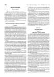
910096-M Hydraulic Impact Wrench - 7/16"
EXPLODED VIEW OF THE HYDRAULIC IMPACT WRENCH -7/16"
51
(0
12
\
10
"
)
36
/
31
IJ
.. / /
Parts Lists and Illustrations
Section 4
The following parts lists are sorted by description, in alphabetical order, and grouped by the assembly
that the individual parts are used on. The lists provide the part description, quantity used I required
and part number for each part, as well as the part number of the assembly that the part is used on. A
"List" in the "Dwg" column indicates that a parts list for the assembly is included in Sections 5.2 or
5.3 of this manual. A "Dwg" in the "Dwg" column indicates that a drawing of the part (with parts list)
is included in Section 5.4 of this manual.
Section
Section
Section
Section
4.1
5.1
5.2
5.3
5.4
Recommended Spare Parts List
Standard Parts List
Customer Options Parts List
List of Illustrations
Recommended Spare Parts List
The following parts are commonly used consumable, wear and / or routine maintenance
items. We recommend that these parts be stocked in the quantities indicated below to
maintain your machine at peak performance.
Hydraulic Impact Wrench-7/16" Recommended Spare Parts List
!
Qty
Description
Part No.
Item
No.
Used on
-
4.2
Standard Parts List
This list includes all serviceable parts used on a standard model machine that has no
customer options installed. See Section 5.3 for parts used on optional features that are
added to the standard model.
NOTE: SEE EXPLODED VIEW DWG. OF HYD.IMPACT WRENCH-7/16" B.O.M.FOR PARTS.
l
PIN:
...
910096
Item
Qty
Description
VALVE HOUSING
FITTING
PIVOT BOLT
COVER
CAP SCREW, 8-32
SPOOL
TRIGGER
CAP SCREW, 10-24
7/16" IMPACT MECHANISM ASSEMBLY
SPACER
THRUST BEARING
THRUST BEARING WASHER
HYDRAULIC MOTOR ASSEMBLY
SNAP RING
1
1
1
1
2
1
1
3
1
1
1
1
1
2
Part #
,D0a. \l (j\
I OOO~<6OS
!D(X)~S3~
IOOOz..8l0
/oac ~~ 01
No.
1
2
3
4
5
6
~
.,: -.
7
8
9
10
11
12
13
14
Used On
910096
-
-
-
-
4-1
910096-M Rev1 Draft 21 Feb 03.doc
r
COVER
SPRING
a-RING (.56" 0.0. X .44" 1.0.)
CAP SCREW, .25-20 NC
LOCKWASHER
DIRECTION SPOOL
BUTTON
FLATHEAD CAP SCREW
a-RING
FLUIDIC TUBE
NUT, (8-32)
RETAINING RING
SHAFT SEAL
BEARING
HOUSING
a-RING
SHAFT
KEY
SPIRAL CLIP
RETAINING RING
GEROTOR
a-RING
CAP SCREW
ROLL PIN
7/16" HEX ANVIL ASSEMBL Y
~.'
/
1
1
2
4
3
1
2
2
4
2
2
1
1
1
1
1
1
1
1
1
1
1
7
2
1
THRUST LOCK·,....
THRUST RING .~
SPRING
RETAINING SLEEVE
BALLS - ANVIL
··ANVIL
HAMMER CASE (INCLUDES ITE~.t1 50)
HAMMER CASE GASKET
GASKET RETAINER
HAMMER BUSHING
HAMMER
HAMMER FRAME
HAMMER PIN
2
2
1
1
.'
/oooa
~~
i-Ibo181
L.../ 00 qOfo
400795
t ~ao (~tb \t)
J..~O\ '5 b 3'D
\ DOt>;lCO\ 3
~t;oOLfI4q
lDOO a~\q
~ S0\ 101lt1
~l<&OO~
4lPiJ5JL{
3
r"
1
1
1
1
1
2
1
2
1600~~65
2
aS~lq816
1
~?olq1o(p
1
1
1
1
1
2
3
1 SET
1
QUAD RING
FITTING
3/8 INCH DIAMETER BALL
BEARING
WASHER
HANDLE SUB ASSEMBLY
SPRING
a-RING
HELl COIL
LEE PLUG
a-RING
15
16
17
18
19
20
21
22
23
24
25
26
27
28
29
30
31
32
33
34
35
36
37
38
,39
40
41
42
43
44
45
46
47
48
49
50
51
52
53
54
55
56
'57
59
60
62
64
65
66
67
68
-
-
t
4-2
910096-M Rev1 Draft 21 Feb 03.doc
f'
:.,r"
Operating and Service Manual
Hydraulic Impact Wrench
(Reference Serial Number Plate)
('
- 7/16"
Racine Railroad Products
1524 Frederick Street
Racine, WI 53404-7577
Phone: (262) 637 - 9681
Fax: (262) 637 - 9069
910096-M Rev1 Draft 21 Feb 03.doc
Record of Chang§
Use this page to record changes, updates and corrections made to this manual.
Rev. / Chg. / Bulletin
Date
No:
16JAN03
Rev 1
!
Description of Changes
Initial Release
i
,
!
Initials
RA
!
i
I
I
1
1
I
I
I
i
1
i
I
i
!
!
r
I
,
I
i
i
\
~
\
;
i
!
1
i
I
I
i
I
I
I
\
I
i
I
i
!
I
I
I
!
I
I
!
1
1
\
\
I
910096-M Rev1Draft 21 Feb 03.doc
Table of Contents
Cover Page
Record of Changes
Table of Contents
List of Figures & Tables
i
······································· ii
······
iv
Section 1 General Information and Overview
. 1.1
1.2
1.3
1.4
1.5
1.6
1.7
1.8
1.9
1.10
1.11
2-2
Purpose
Cancellation
Scope
Definitions
General Safety Precautions and Devices
Machine Description and Specifications
Machine Identification
Machine Components and Major Assemblies
Operator Controls
Service Manuals and Tools
Warranty Terms and Conditions
2-2
2-2
2-2
2-2
2-2
2-3
2-6
..
2-7
..
2-8
2-1
Section 2 Initial Set-up and Adjustment
2.1
2.2
2.3
Inspection and Warranty Registration
Initial Assembly and In-Service Maintenance
Setup and Adjustments
2-1
2-1
2-3
3-1
Section 3 Operating Procedures
3.1
3.2
3.3
3.4
3.5
3.6
3.7
Safety Precautions and Devices
Transportation & Handling
Normal Operating Parameters
Normal Start-up Procedures
Normal Operating Procedures
Normal Shut-Down Procedures
Emergency Procedures
-_
Section 4 Maintenance Procedures
4.1
4.2
4.3
4.4
4.5
_
Safety Precautions and Devices
Daily Inspection, Fueling and Lubrication
Routine Adjustments and Maintenance
Trouble Shooting
Special Tools
3-2
3-3
3-3
3-3
.
'"
Recommended Spare Parts List.
Standard Parts List
Customer Options Lists by Serial Number
List of Illustrations
'"
Section 6 Parts and Service Support
6.1
6.2
6.3
3-2
-
Section 5 Parts Lists and Illustrations
5.1
5.2
5.3
5.4
3-1
3-1
3-1
3-1
3-1
3-2
3-2
4-1
4-1
4-1
4-3
.
5-1
Non-Warranty Parts Sales
Technical Support & Service
Warranty Parts & Service
5-1
5-1
5-2
ii
910096-M Rev1 Draft 21 Feb 03.doc
Table of Contents
Section 7 Appendices
7.1
7.2
6-1
Sales Representatives
6-1
iii
910096-M Rev1 Draft 21 Feb 03.doc
This list identifies where photos, tables and other figures are located within the text of this manual. All
parts lists and drawings are provided in Section 5.
Figures
Figure
Figure
Figure
Figure
Figure
Figure
Figure
1
2
3
4
5
6
7
Hydraulic
Hydraulic
Hydraulic
Hydraulic
Hydraulic
Hydraulic
Hydraulic
Impact Wrench-7/16"
Impact Wrench-7/16"
Impact Wrench-7/16"
Impact Wrench-7/16"
Impact Wrench-7/16"
Impact Wrench-7/16"
Impact Wrench-7/16"
-
Front Cover Page
Left Side View
Right Frontal View
Showing
Showing
Manufacturer's Data Plate
Caution Decal.
,
'"
1-1
2-4
2-4
2-5
2-5
2-6
3-5
2-1
910096-M Rev1 Draft 21 Feb 03.doc
Section 1
1.1
General Information and Over view
Purpose
This manual provides general instructions for operating and maintaining the Racine Railroad
Products Hydraulic Impact Wrench-7/16".
1.2
Cancellation
Not Applicable, Initial Release. Record subsequent changes made to this manual on page i.
1.3
Scope
This Bulletin applies to all Racine Railroad Products Hydraulic Impact Wrench-7/16" power
tool Reference Serial Number Plate.
1.4
Definitions
This manual uses the following standard terms for clarity:
1.4.1
DANGER' An operating procedure. practice, or condition, etc., which WILL RESULT IN
INJURY OR DEATH if not carefully observed or followed.
1.4.2
WARNING! An operating procedure. practice, or condition, etc., which may result in
injury or death If not carefUlly observed or followed.
1.4.3
Caution! An operating procedure, practice, or condition, etc., which may result in
damage to equipment if not carefully observed or followed.
1.4.4
Note: An essential operating procedure, practice, or condition, etc.
1.5
General Safety Precautions and Devices
WARNING! Failure to follow safety precautions when operating this equipment can result in
serious injury or death to the operator or other persons in the area. Observe the following
precautions whenever you are operating, working on or near this equipment.
Always wear appropriate work clothing when operating this equipment. DO NOT WEAR
loose clothing, jewelry, radio belts, etc., when you are operating, working on or near this
equipment.
2-2
910096-M Rev1 Draft 21 Feb 03.doc
1.5.1
Always wear appropriate personal protective clothing when operating this equipment
(e.g. Orange safety vest, hard hat, safety glasses with side shields, full-face shield,
hearing protection, steel-toed safety boots, leather gloves, dust respirator, leggings, etc.).
1.5.2
Always lift heavy objects with the knees and legs (not the arms and back). Always use
care when carrying the Hydraulic Impact Wrench and ensure proper footing and crew
coordination when carrying or positioning the Hydraulic lmpact Wrench.
1.5.3
This equipment may be operated from either side of the rail. Remove ballast that may
hinder the proper placing of the Hydraulic lmpact Wrench verses the rail work area.
1.5.4
Keep your hands, arms, feet. head, clothing, etc., out of the operating area and away
from all rotating or moving components when you are operating, working on or near this
equipment.
1.5.5
Ensure that all guards, covers, hoses and operating components are in good working
order and that all controls are in the appropriate position before starting the engine.
Ensure that installed safety equipment (e.g. fire extinguishers, first aid kits, locking and
safety devices) are installed properly and are in good working order. DO NOT
OPERATE the machine until unsafe conditions have been corrected.
1.5.6
Operate the POWER SOURCE ENGINE only in a well-ventilated area and ensure that
the air filter(s), air filter cover(s), muffler are in good condition. DO NOT crank the engine
with the spark plug removed.
1.5.7
Keep the machine clean and free of debris. Operate the machine in a safe and
responsible manner. Exercise caution when working on or near rotating or moving
components, hot components and fuel systems. Be aware of potential fire hazards and
prevent sparks. , etc., from starting fires on right-of way.
1.5.8
Comply with all instructions provided on any decals or placards installed on the machine
and with any relevant amplifying information provided in this manual or other general
operating procedures.
1.5.9
When you leave this equipment, even for a short time, shut off the hydraulic motor and
disengage the hydraUlic supply hoses.
1.5.10
Shut off the power source engine, ensure that all controls are in a safe position and install
all appropriate locking and safety devices before doing any of the following:
•
•
•
•
1.5.11
1.6
Lubricating
Adjusting
Making Repairs
Performing Service
Comply with all Lock Out / Tag Out Procedures and other safety procedures established
for your work environment.
Machine Description and Specifications
The Racine Railroad Products Hydraulic Impact Wrench-7/16" is a portable, remotely
powered, hand held power tool designed for drilling holes in wood cross-ties, trestle-work and
2-3
910096-M Rev1 Draft 21 Feb 03.doc
road crossings for lag screw or structural fastener installation. The Racine Railroad Products
Hydraulic Impact Wrench-7/16" accommodates light impact auger bits.
Figure 2 Hydraulic Impact Wrench-7/16 Right Hand View.
Figure 3 Hydraulic Impact Wrench-7/16" Operators View.
2-4
910096-M Rev1 Draft 21 Feb 03.doc
'{J'
Figure 4 Hydraulic Impact Wrench Operator's View.
Figure 5 Hydraulic Impact Wrench-1/16" Drive Socket View.
1.6.1
Manufacturer:
Racine Railroad Products, Inc.
1524 Frederick Street
P.O. Box 044577
Racine, WI 53404-7577
2-5
910096-M Rev1 Draft 21 Feb 03.doc
~
1.6.1
,
Phone:
E-mail:
Website:
(262) 637-9681
[email protected]
http:\\www.racinerailroad.com
Physical Data:
Tool Specifications: 7/16" Quick Change
Hydraulic System:
Open-center or Closed-center
(-23.0 cm)
Length:
9.00 in.
(-7.60 cm)
Width:
3.00 in.
(-23.0 cm)
Height, Work Mode:
9.00 in.
(-3.29kg)
Weight: (less tools)
7.25 Ibs.
Options and Accessories:
Sockets and adapters
Contact: Racine Railroad Products
1524 Frederick Street
P.O. Box 044577
Racine, WI 53404-7577
Phone: (262) 637-9681
(262) 637-9669
Mechanical Data
Hydraulic Motor:
Gerotor type
4-7 gpm
(-15-27Ipm)
Maximum Flow:
(-6.9-13.8 MPa)
Maximum Pressure:
1000-2000 psi
Maximum Impact Time:
10 seconds
Drive Size:
7/16" socket (-1.11 cm)
(610 NM @ 19 LPM)
Torque
450 ftllbs @ 5 GPM
(13.8 Mpa)
Setting at tool:
2000 psi
200 psi
(1.38 Mpa)
Back Pressure
25 Micron (Nominal)
Filtration:
Pressure & Return Ports: NO.6 (9/16"-18 UNF) SAE O-Ring
1.6.2
Performance Data:
Production Rate:
1.7Machine Identification:
The Manufacturer's data plate is located on the side of the assembly. Please provide the
Racine Railroad Products Model and Serial Number, and any locally assigned identification
number, to our customer service personnel when contacting the factory for parts, service or
warranty support.
Figure 6 Manufacturer's Data Decal.
2-6
910096;.M Rev1 Draft 21 Feb 03.doc
1.7
Machine Components and Major Assemblies
1.7.1
The Socket spindle and impacting mechanism assembly.
1.7.2
1.7.3
1.7.4
1.7.5
The
The
The
The
1.8
Operator Controls
Hydraulic motor and adapter asserrlbly.
Hydraulic control valve/trigger group with housing.
Handle group with hydraulie porting.
Hydraulic whip hose assemblies.
Refer to Figures 1 through 5 to identify and locate the controls and major components of the
Hydraulic Impact Wrench-7/16".
1.8.1
1.9
Service Manuals and Tools
1 .9.1
Operating and Service Manuals: One Operating and Service Manual is provided with
each machine. Manuals are shipped with each machine.
1.9.2
Operating and Service Manual Changes: The Operating and Service Manual may be
updated to reflect product development and/or revised operating and maintenance
procedures. If appropnate, Service Bulletins may be released to provide additional
operational, maintenance and/or safety information. Record all changes made to this
Manual in the Record of Changes on page i. Submit recommendations and requests for
Operating and Service Manual Changes to:
Racine Railroad Products, Inc.
Attn: Technical Service Manager
1524 Frederick Street
P.O. Box 044577
Racine, WI 53404-7577
Phone:
(262) 637-9681
E-mail:
[email protected]
Website:
http:\\www.racinerailroad.com
2-7
910096-M Rev1 Draft 21 Feb 03.doc
.
~\
1.10
Warranty Terms and Conditions
1.10.1
Warranty Period: Each new machine, and new parts of our manufacture, are warranted
against defects in material and workmanship for one year from the date of shipment from
our factory. When contacting the factory for parts, service or warranty support, please
provide the Racine Railroad Products Model and Serial Number and any locally assigned
identification number to our customer service personnel to help them identify your
machine and better serve you.
1.10.2
Vendor Parts Warranty Period: Other equipment and parts used, but not manufactured
by Racine Railroad Products. Inc.. are covered directly by the manufacturer1s warranty for
their products.
1.10.3
Warranty Parts and Service: We Will repair or replace, without charge, F.G.B. factory,
Racine, Wisconsin, USA. any part of our manufacture which is proven to be defective
during the warranty period.
Material claimed defective must be returned, if requested, to the factory within 30 days
from the date of the claim for replacement. Ordinary wear and tear, abuse, misuse and
neglect are not covered by this warranty.
Depending upon the circumstances. we may provide technical assistance and/or
technical service support. Without charge. to assist in the correction of warranty related
problem.
1 10.4
Non-Warranty Parts and Service: Material damaged through normal wear and tear,
abuse, misuse and/or neglect are not covered by this warranty. Non-Warranty Parts and
Technical Service policies and procedures are provided in Section 6 of this manual.
2-8
910096-M Rev1 Draft 21 Feb 03.doc
\
Section 2
2.1
Initial Set-up and Adjustment
Inspection and Warranty Registration
The Hydraulic Impact Wrench -7/16" is normally shipped via common carrier in a cardboard
carton. The warranty period begins on the date of shipment from our factory. Upon delivery
by the carrier. inspect the Hydraulic Impact Wrench and shipping materials for damage.
Ensure that all items indicated on the packing list have been received. Address items lost or
damaged in shipment with the freight carrier.
2.1.1
Removing Packing Materials / Delivery Inspection: Remove the packing materials and
inventory the contents of the packing list. Ensure that Operating and Service Manuals,
tool kits and any other materials sent with the machine are in good condition.
2.1.2
Product Registration Card: Please fill out and return the Product Registration Card to
help us better serve you. Your feedback on the Product Registration Card helps us
improve our products and service.
Note: Unless otherwise Indicated, the address and contact name provided on the
Product Registration Card will be the mailing address for future Service Bulletins and
Customer Service Information.
Note: Please contact our Service Department at the address provided in Section 6 of
this manual If you have any problems with or questions about your new machine.
2.2
Initial Assembly and In-Service Maintenance
The Hydraulic Impact Wrench-7/16" was tested after assembly at our factory. After
asserrlbly, the machine should receive a thorough In-Service inspection before initial
operation. If you do not feel qualified to perform this In-Service work yourself, contact a
competent mechanic or the Racine Railroad Products Service Department for technical
support.
2.2.1
Uncrating a new machine: Support the Hydraulic Impact Wrench-7/16"and cut the
banding (if any) to release the machine from the shipping carton. Manually lift the
Hydraulic Impact Wrench-7/16". options and accessories separately and clear of the
carton and place on a safe surface.
2.2.2
Initial Assembly: After unpacking and inspecting the Hydraulic Impact Wrench-7/16"
,options and accessories prepare the unit for service by doing the following:
Hydraulic Systems:
Use a calibrated flow meter and pressure gauge to check the hydraulic power source
for 5 -10 gpm/20-38 Ipm at 1500-2000 psi/100-400 bar.
• A relief valve setting between 21 00-2250psi/145-155 bar is required for the
operation.
• The hydraulic system's back pressure should be less than 250 psi/17 bar, n1easured
at the tool end of the operating hoses. All system's checks should be made at
minimum operating temperatures (maximum fluid viscosity of 400 ssu/82 centistokes.
• The hydraulic fluid cooling system should limit maximum fluid temperature to 140
F/60° C at the maximum expected ambient temperature. The minimum cool capacity
0
2-1
910096-M Rev1 Draft 21 Feb 03.doc
should be 5 hp/3.73kW at a 40° F/22° C difference between ambient temperature and
fluid temperature.
A minimum of 25 micron filtration is required for the hydraulic system. For cold
weather startup and maximum dirt holding capacity a filter element sized for 30
gpm/14 I cpm is recommended.
Hydraulic fluid requirements:
•
•
Viscosity (Fluid Thickness)
U.S.A.
METRIC
50° F 450 SSU Max.
100 0 F 130-200 SS U
140 0 F 85 SSU Min.
10° C 95 Centistokes
38° C 27-42 C.S.
60 0 C 16.5 C.S., Min.
Pour Point 10° F/23° C Minimum (for cold startup)
Viscosity Index (ASTM 0 2220) 140° F Minimum
Demulsibility (ASTM 0-1401) 30 Minutes Maximum
Flash Point (ASTM 0-92) 340 F/171 C Minimum
Rust Inhibition (ASTM 0-665 A & B) Pass
Oxidation (ASTM 0943) 1000 Hours Minimum
Pump Wear Test (ASTM 02882) 60 mg Maximum
0
0
•
•
Recommended hose size: .500 inch/12mm 1.0. up to 50 fi./15m long
Recommended hose size: .625 inch/16 mm 1>0> up to 100 ftl30 m tong
•
The Racine Hydraulic 910098 power unit is recommended for hydraulic supply. This
unit is equipped with two 5 gpm/20 Ipm circuits that can be combined for one 10
gpm/40 Ipm circuit.
If the tool is used in cold weather, preheat the hydraulic fluid by running power source
at low engine speed. Fluid temperature should be at or above 50 0 F/10° C (400
ssu/82 centistokes) before use, when using recommended fluids. Using too thick of
fluid may result in tool damage.
CHECK THE POWER SYSTEM TYPE: THE HYDRAULIC IMPACT-7/16" MAY BE
USED WITH OPEN OR CLOSED CENTER SYSTEMS.
Check hydraulic hosed for cracks. leakage and damage. If the hoses or couplers
show any of these wear characteristics. replace them before operating the tool.
NEVER attempt to locate leaks with your hands, personal injury may occur from
pressure system.
•
•
•
Tool Trigger
•
•
Check that trigger presses toward handle easily and returns to the "OFF" position
when released.
If trigger sticks or does not operate easily check for obstructions. If trigger does not
return to Off' position when released, check the return springs. DO NOT OPERATE
A TOOL IF THE TRIGGER IS NOT WORKING!
II
Hose Connecting
•
•
•
•
Wipe quick couplers with a clean lint free cloth before connecting them.
Connect hoses from power source to the tool. It is recommended that you connect
the return hoses first and disconnect last to minimize or avoid trapping pressure
within the tool.
When connecting the quick couplers, the flow should run from male coupler to female
coupler. The female coupler on the tool is the inlet. Quick couplers are marked with
an arrow to show flow direction.
Turn on the hydraulic circuit at your power source.
Note: When possible, connect the free ends of uncoupled hoses to prevent pressure
build up in the hoses. The sun can also increase pressure in the hoses and make
connecting difficult
2-2
910096-M Rev1 Draft 21 Feb 03.doc
•
•
•
•
2.3
Be sure the pressure hose is connected to the pressure port and the return hose
connected to the return port. Pressure port is at the position and return port is at the
position. See parts view if uncertain.
Do not attempt to reverse the tool by hooking the pressure hose to return port of the
tool. The wrench is equipped with a spool to reverse the direction of rotation.
Reversing the hoses can cause severe damage to the wrench.
Sockets and Accessories
Do not use drills bits or accessories which are not intended for impact type
applications. They may crack or fracture during use. Use only impact rated sockets
and accessories.
If adapters are required, use components which are in good condition only. Loose,
multiple adapters and excess weight between the wrench and socket can reduce the
intensity of the impact to the nut or bolt head.
Setup and Adjustments
The Hydraulic Impact Wrench-7/16" is a power tool that requires familiarization by the end
user. It is highly recommended that this manual be referred to before attempting a testing
exercise with the Impact Wrench.
2-3
910096-M Rev1 Draft 21 Feb 03.doc
Operating Procedures
Section 3
3.1
Safety Precautions and Devices
Before operating the Hydraulic Impact Wrench -7/16" perform a daily inspection of the tool
as described in Section 4.2. Ensure that all general safety precautions are observed and that
proper personal protective clothing is worn as described below.
I
Figure 3.1-1
•
•
•
•
•
•
3.2
Personal Protective Equipment: At-a minimum, the following Personal
Protective Equipment should be worn by the operator:
Safety Glasses
Hearing Protection
Safety Helmet
High Visibility Safety Vest
Leather Work Gloves
Steel Toed Safety Shoes
Transportation & Handling
The Hydraulic Impact Wrench - 7/16" is typically transported to the job site by truck or rail.
Upon arrival at the Job site. the Hydraulic Impact Wrench IS lifted into position manually.
3.3
3.3.1
Normal Operating Parameters
Motor: 4-7 GPM
Maximum Speed: 620 RPM
3.3.2
Performance Data:
MAX IMUM 450 FT./LBS. OF TORQUE AT 2000 PSI
Production Rate:.RECOMMENDED 10 SECOND INTERVAL PER APPLICATION
3.4
Normal Start-up Procedures
Before starting the Hydraulic Impact Wrench-7/16", perform a daily inspection as described in
Section 4.2.
Caution! DO NOT OPERATE IMPACT WRENCH WHEN BYSTANDERS ARE NEAR
THEWORK AREA
Note: Depending on temperature, let the hydraulic motor warm up before applying full
load.
Caution! DO NOT OPERATE IMPACT WRENCH NEAR FLAMMABLE MATERIALS
OR ENERGIZED TRANSMISSION LINES.
Normal Operating Procedures:
3-1
910096-M Rev1 Draft 21 Feb 03.doc
•
•
•
•
•
•
The Racine Railroad Products Hydraulic Impact Wrench - 7/16" is designed to efficiently
drill holes and loosen nuts and bolts. The tool uses a 7/16" inch socket drive and
requires high impact drill bits. The wrench may be used for other applications where
impacts are typically used.
The wrench is equipped With a spool which reverses the drive direction. Insulated
handles reduce vibration and operator fatigue. The safety lock on the trigger helps
prevent accidental starting of the tool. A rotating front handle allows comfortable
operation in both the vertical and horizontal positions.
Operation
With hydraulic power source connected to the tool, shift the spool to the direction of
rotation desired. When standing behind the tool (the hose end) pushing the spool to the
right rotates the socket clockwise, and to the left rotates counterclockwise. Do not shift
the spool while the tool IS operating, damage to internal components may occur.
Grasp both handles firmly, place socket on fastener, squeeze the trigger lock to the
handle and pull the trigger toward the handle grip activating the tool. Always hold the
tool with both hands to maintain control.
To stop the Impact Wrench-7/16" just release the trigger.
When the fastener contacts the surface of the material being fastened, limit impact time
to 10 seconds. Excessive wear will occur to the hammer mechanism due to the heat
build up.
•
Shut-Down Procedures
To safely transport and store the Hydraulic Impact Wrench-7/16" perform a normal shut down
as follows:
1. Stop the Hydraulic Impact With the spring loaded trigger release valve..
2. Shut down the hydraulic power source.
3. Disconnect the hydraulic hoses from Hydraulic Impact Wrench ..
4. Remove the socket or adapter tool.
4. Prepare the unit for transport as outlined in Section 3.2 above.
Note: A photo and detailed discussion regarding the operation of the Controls are provided
in Section 1.9.
3.5
Emergency Procedures
In the event of any malfunction, IMMEDIATELY SHUT-OFF THE HYDRAULIC POWER
SOURCE and correct the problem.
WARNING! DO NOT PERFORM MAINTENANCE ON THE HYDRAULIC IMPACT
WRENCH WHILE THE POWER SOURCE OR HYDRAULIC IMPACT WRENCH MOTOR
ARE RUNNING.
Section 4
3.6
Maintenance Procedures
Safety Precautions and Devices
Normal maintenance of the HydraUlic Impact Wrench can be performed without any special
.maintenance related safety devices. Before operating the HydraUlic Impact Wrench-7/16",
perform a daily inspection of the power tool as described in Section 4.2. Ensure that all
general safety precautions are observed and that proper personal protective clothing is worn
as described in Sections 1.5 and 3.1.
3-2
910096-M Rev1 Draft 21 Feb 03.doc
WARNING! DO NOT PERFORM MAINTENANCE ON TH"E HYDRAULIC WRENCH WHILE
THE MOTOR IS RUNNING OR HOSES ARE CONNECTED.
3.6.1
Safety Devices: Upon completion of maintenance, ensure that the foffowing Safety
Devices are installed on the Hydraulic Impact Wrench-7/16":
•
•
•
•
•
3.6.2
3.7
The Impact Wrench is working properly.
The handles and trigger/trigger locks are secured.
Lubrication of the wrench is in order.
Hydraulic hoses are safe to use and connected securely.
The sockets and accessories are in good condition.
No Special Procedures Required, See Local Requirements.
Daily Inspection and Lubrication
At a minimum, perform the following routine daily maintenance on the Hydraulic Impact
Wrench -7/16" to keep it in good working condition.
3.7.1
Daily Inspection: Before operating the Hydraulic Impact Wrench-7/16;1t', inspect the
following and correct any problems as necessary:
•
•
•
•
General Condition of the tool.
All Guards and Safety Devices are Installed and Operable.
All Controls are Operable.
Hose Condition
Grease Type and Locations: Bearing and bushings are used on the Hydraulic Impact Wrench to
reduce daily maintenance. Ensure that all bearings and moving parts are properly lubricated with
on weekly intervals. Semi-annually remove the impact head and clean the grease off the impact
components. Also remove the grease from the impact housing Remove the thrust washers and
thrust bearing and wipe clean. Before reinstalling them, check for damage and replace if in poor
condition. Mount the impact head to the motor adapter after placing the assembled hammer
mechanism in the impact head. Make sure all parts are in proper position before mounting the
impact head. Apply grease prior to re-assembly ..
3.7.1.1
3.8
Lubricating Grease Type: Mobile HP 53019-6 or equivalent
Routine Adjustments and Maintenance
This section outlines basic adjustments and maintenance required for daj~y operation of the
Hydraulic Impact Wrench-7/16". These instructions are intended for operator level, field
maintenance and not repair shop or overhaul level procedures.
3.9
Trouble Shooting
The following chart can be used as guide to correct any problem you may be experience with the
Hydraulic Impact Wrench - 7/16"".
To determine the problem in operation of the impact wrench, always check that the hydraulic power
source is supplying the correct hydraulic flow and pressure to the tool as listed in the table. Be sure
you are using an accurate flow-meter. Check the flow with the hydraulic fluid temperature at least 80 0
F/27° C. Always check the power source and hoses before disassembling the impact wrench.
3-3
910096-M Rev1 Draft 21 Feb 03.doc
Possible Cause
Problem
Tool will not operate.
Remedy
Tool not properly connected.
Check pressure and return
connections and disconnects.
Low oil volume and/or
pressure.
Check hydraulic power source.
Tool will not operate if inlet
pressure is below 1000 PSI or
flow is less than 4 GPM.
Low oil volume and/or
pressure
Check hydraulic power source
for recommended flow,
pressure and proper conditions.
Contaminated hydraulic
system.
Relief valve blocked or
contaminated
Remove contamination and
clean hydraulic system.
Check relief valve. Clean or
replace as necessary.
Excessive pressure or flow.
Verify correct hydraulic power
source is being used
I
I
Tool runs at low speed
Tool runs too fast
Oil leakage from trigger area.
Damaged O-rings in spool
Adjust hydraulic power supply
Replace a-rings.
Factory Service Required.
Actuation Trigger sticks
Excessive flow
Factory Service Required
Broken spring
Check trigger, sleeve spool for
binding. Replace spring.
Contamination
Check for dirt or deposits
Clean sleeve and spool.
Check hydraulic system
Clean conponents.
Trigger binding (trigger bent,
trigger pivot pin too tight, etc.
Inspect, adjst trigger where
binding occurs.
Excessive flow
Reduce RPM of engine.
Inefficient cooling.
Increase reservoir size and/or
add oil cooler.
Tool components loose.
Factory service may be
required.
Replace worn or damaged arings or gaskets.
Disassemble tool. Replace
worn or damaged components ..
Tool Trigger plunger sticks
or works hard
Systems overheats.
Hydraulic oil leakage from
trigger area.
WARNING!
Do not use tool. Tool with
leak may cause severe bodily
injury.
Damaged a-rings or gaskets.
Tool components worn or
damaged.
3-4
910096-M Rev1 Draft 21 Feb 03.doc
Power source works but tool
lacks power or does not
operate.
Inappropriate hydraulic system.
Check type of hydraulic power
source: open -center or closedcenter.
3.10 Special Tools: None specified
.mm\\B1II
MAX. FLOW: 5GPM/20lPM
MAX. PRESSURE: 2000 PSI" 50 BAR
o IMPROPER USE MAY CAUSE SEVER INJURY
o READ AND UNDERSTAND OPERATORS MANUAL
BEFORE OPERAllNG TOOL
o KEEP All GUARDS IN PLACE
o DURING OPERATION WEAR GLOVES,
MCL.OTHING AND FOOTWEAR
~OOIlINGDP£RAnONALWAYSWEARAPPROVED
,
,
SAFETY PROTECTION FOR:
EAR
EYE
HEAD
• •0
.
.
Figure 7 Caution Decal
3-5
910096-M Rev1 Draft 21 Feb 03.doc
Placard List, Hydraulic Impact Wrench
Part #
Qty
1
1
Description
PLATE, SERIAL NUMBER
DECAL, LOGO
4.3
910096
PIN:
Used On
465474
Customer Options Lists by Serial Number
These lists include all parts that are specified as customer options and not included in a
base-model. These lists are sorted by customer I option.
I
RRP Sere No: ! RRP Part No: I
!
I
910096
HIWI
i
I
I
i
!
\
'I
i
II
i
i
I
!
Customer Options Parts List
I
1
I
Description
STANDARD MODEL: NOT APPLICABLE
Qty
Part No.
Dwg
Used on
-
-
-
-
4-3
910096-M Rev1 Draft 21 Feb 03.doc
Parts and Service Support
Section 5
5.1
Non-Warranty Parts Sales
Material damaged through normal wear and tear, abuse, misuse and/or neglect are not
covered by our warranty and should be ordered directly from our Customer Service
Department. Parts for models that are no longer in production may not be available.
5.1.1
Parts & Customer Service Address: Please contact us at the following address for parts
and customer service support:
Racine Railroad Products, Inc.
Attn: Customer Service
1524 Frederick Street
P.O. Box 044577
Racine, WI 53404-7577
Phone:
E-mail:
Website:
5.1.2
262-637-9681 Extension: 105
[email protected]
http:\\www.racinerailroad.com
Non-Warranty Parts Orders: When placing a parts order please provide the following
information:
•
•
•
•
•
•
•
Company Name and Billing Address
Purchase Order Number and Issuing Authority
Shipping Address
Special Handling Instructions
Contact Phone Number
Machine Model and Serial Number
Part Numbers and Quantities Being Ordered
Note: Please use Racine Railroad Products part numbers when ordering parts. Racine
Railroad Products part numbers are shown on the parts lists and drawings in Section 5 of
this manual and have only six (6) numbers. Any part number with other than six numbers
(e.g. contains alpha-numeric characters) is a Vendor Part Number and NOTa Racine
Railroad Products part number.
5.2
Technical Support & Service
Telephone and web-based technical support is available for current production models
through our Technical Service Department. Service Manuals and limited technical support
may be available for models that are no longer in production. In the future, Technical Support
features will be expanded on our home page on the world-wide-web.
5.2.1
Telephone and E-mail Technical Support: Telephone and E-mail technical support is
available on normal U.S. business days from 8:00 AM to 5:00 PM U.S. Central Time
Zone (GMT +6 (+5 Daylight Savings Time)). Contact us at:
Phone:
E-mail:
Website:
(262) 637-9681 Extension: 111
[email protected]
http:\\www.racinerailroad.com
5-1
910096-M Rev1 Draft 21 Feb 03.doc
- - - - - - -
5.2.2
Non-Warranty Technical/Field Service Support: Depending upon the circumstances
and availability of technical service personnel, we may provide technical assistance
and/or field service support, at the customer's expense, to assist in the correction of non
warranty related problems. Contact our Technical Service Department to coordinate
Non-Warranty Technical/Field Service Support.
5.2.3
Warranty Technical/Field Service Support: Depending upon the circumstances and
availability of technical service personnel, we may provide technical assistance and/or
field service support, at no charge to the customer, to assist in the correction of warranty
related problems. Contact our Technical Service Department to coordinate Warranty
Technical/Field Service Support.
5.3
Warranty Parts & "Service
Warranty parts and service are coordinated through our Technical Service Department. Our
warranty terms and procedures are provided in Section 1.11 of this manual.
5.3.1
Warranty Parts Claims: Material claimed to be defective must be returned to our factory
for evaluation. Defective materials will be replaced, or your account will be credited if
replacement materials have already been purchased. Please contact our Technical
Service Department at the address provided below if you have any questions or
problems.
5.3.2
Warranty Service Support: Depending upon the circumstances and availability of
technical service personnel, we may provide technical assistance and/or field service
support, at no charge to the customer, to assist in the correction of warranty related
problems. Contact our Technical Service Department at the address provided below to
coordinate Warranty Technical/Field Service Support.
Racine Railroad Products, Inc.
Attn: Technical Service Manager
1524 Frederick Street
P.O. Box 044577
Racine, WI 53404-7577
Phone:
E-mail:
Website:
(262) 637-9681 Extension: 111
techserv@racinerailroad. com
http:\\www.racinerailroad.com
5-2
910096-M Rev1 Draft 21 Feb 03.doc
Section 6
6.1
Appendices
Sales Representatives
For more information about this. or any of our other products, please contact the nearest
Representative shown on our Sales Representatives List.
6.2
The Owner's Manuals provided was current at the time of printing.
6-1
910096-M Rev1 Draft 21 Feb 03.doc