1
SERVICE MANUAL FOR KH-270
ELECTROKNIT.
CONTENTS
I. P RODUCT CHARACTERISTICS ....................................................... I
2. PRODUCT S PF.CTFICATIONS ........................................................... J
3. QUCK TROUBLESHOOTING CHA RT .............................................
4. l'iOTF..<; Of CAUTION FO R CHECKING AND RF.PAIR ........... ...... .
5. CIRCUITRY CONFIC.t:RATIO:'I ............................... .........................
5. 1 Co<rtrol PC Boord .......................................................................
5.2 M ain P C Boord .. .................................................... ....................
S.3 I .eft Pooilion ~ P C Board ond Riehl Position Sensor
PC Boord ....................................................................................
S.4 Encoder P C Boo.rd ............................................................ ..........
5.5 Solenoid P C Boord .....................................................................
5.6 Relorio•ship bdwetn Netdle Selector Plate, Solenoid, and
Needle Number .............. ............................................................ .
5.1 The relation between knillin~ mochine & PPD Cartridge ...... .......
5.8 !'ower ............................... ................ ......... .......................... .......
6. Tf.ST PROGRAMS .............. ......... .......... .................................. ...........
6.1 Tt'St 8&5 ......................................................................................
6.2 Test 888 .......................................................... ............................
6.3
T~t
2
4
S
S
S
s
5
S
6
6
7
8
8
9
889 .................................................................................... 10
1. CHECKI:"'C TilE NEEDLE SELECTOR .......................................... 11
7.1 C hecking with 1~ Po wt'l' Switch Turned Off ............................. 11
1.'2 Ch<ekinR with ~~ Powtr Switch Turn td On .............................. 11
7.3 Ch<eking with I~ Solenoid O n ................................................. 11
7.4 Ch<ekinc tltt Solen()ld ............................................................... 12
1.5 Ch<ekinR I'it edle Selection b)' Test Pattern ................................ 13
8. CHECKI:'IIG TH£ A.C. ADAPTER .................................................... 14
9. REMOVI:'IC EL.ECf KICAL/ t:Lt:CTRO:'IIU.: PARTS AND
PC BOARDS ...................................................................................... IS
9.1 Rtmooinalhe Batltry ond Co ntrol P.C. Board ..........................
9.2 Removinc lhe Moin P.C. Board ..........................-...................
10. WHEN CRJ:ATf.O PATTT.RN DIS APPEA R WITH POWER
SWITCH ON .................................. ... .......................... ... ... ..................
II . DISASSEMBLY, ASSEMIIUNC, AND ADJ USTMENT OF
CARRIAGE ................................................................................. ...... .
11.1 Oi...o...,mblin& lbt Carriace ......................................... ... .......... .
11 .1 AMombllnc the Curia.c e .................................................... ........
IS
IS
16
11
J7
23
11 .3 Cbecl<ina tltt Curiaae Functi.,. - 1- ....................... .......... .... 29
11.4 Clotckinc l bt Curioge Functions -2- .. .................................. . 341
ll .S How to Adj111t l bt Corriqe ...... ........ ........................................ .
or t:ach Carriage Com ........................... .
12. OIS ASSEMBL V AND ASSEMBL'Y o•· nu; MAIN BODY .. ...........
12.1 Disassembling the Main Body ......................... ..........................
12.2 As.wmbtinc t ht Main Body ........................................................
12.3 How In Adju•tlht Needle Bed Comb ........................................
13. ADJUSTMEJiiT AND CHECK OF THE NEF.DI.F. SF.LEC:TOR
MF.CHANISM ............................................................................... .....
13.1 Adju• ling t bt Ca.rd Ruder Culcle Plate .....................................
13.1 Adjust in~ t he .lluta ry Ca,. PoMtiun ...........................................
13.3 Chocking the Nttdlt Selector M e<hanism ..................................
11 .6 M ounting l>imeMlon•
31
34
35
35
37
41
42
42
42
43
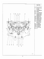
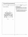
1. PRODUCT CHARACTERISTICS
I.
2.
2. PRODUCT SPECIFICATIONS
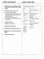
The application or el«:tronics to a pattern knittin,~ device, and automatic
needle selection fbrouglt the internalization of pattern data utili~ing a
microcomputer.
: Weight
Patterns stored in memory may be altered in a variety of way<:
--------------~r-
Pitch, number of n~edles
(!) The orientation or the pattern may be changed.
·(b: The pattern may be expanded to two times hori2ontally as well as
vertically, and up t<.> four times by expanding the pattern two times in
both directions simultaneously.
Q) The pattern may he knitted face to facejback to back.
@) :"'egative and K RC patterns may be knitted by merely switching the
pattern variation key.
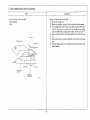
3.
Large si-ted patterns n~ay be knitted.
f 12 stitches 998 rows x 2 • 112 stitches 246 rows
4.
5.
Pattuns stored in memory are not erased when the power is turned off.
6.
Original pattern data may be stored or called up with stitch pattern
cartridge Ill.
7.
Thread lace may be knitted " 'ith K carriage.
Size
l1.2J 7 mm x W 241 mm x H 92 mm
Culor
White
Needle hed material
Tempered steel can be installed
Knit reader
KLI 16 may be used
!
·J
r
------~r----
KR-KR(' usage
KR260, KRC900
lntersia carriage may be used (KA-2600)
Patte-rn programming
tie.vice
PI'D-120 may be u;ed
Voltage-power
requirements
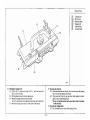
< Accessories>
• Pattern hook
• D(.·sign sheet
-I-
-
16 kg
Pauem need le device
Original patterns may be knitted through key Input.
9 mm, 114 needles
---
Automatic needle sele.:tion by internal
mlcrocomputer
AC adapter 7.5V I A
-'
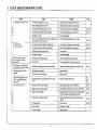
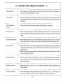
3. QUICK TROUBLESHOOTING CHART
Troublt
K carriage docs not move easily
ll.
M
..
E
u
"'
Origin
I. Oillhe buu of the needle and the stitch cam
2. Needle bed sliding. ·van is Ollt of oiJ
3. The sinker plate and gate peg are i 1l Cl)I\LaCt
2, Oil !ronl and rear rails or body and carriage
Floating stitches.
Stitches g<'t tucked.
-
4 . The sinker plate is lifting the knitting Jteed1e.
5. 'llte gage is too tight
5. l.oosen knitting gage
Pooc hotiz.o.ual adjustment of rotary cam. (Rotary ,,.m
is po~itioned too much to I he left.)
..
.s
-~
~
When the change knob is set to
< KC>. end needle selection is
not possibU:
Wron8 ueedk i!> :o;l'!h~ctcd
"
0
·~
~
.!!
"'z8
- -.,
2. To.o much gar he:aween sinker plate and needle
4. Tho gog< <s lOO t ight
The carriage gets stuck while
knitting
·-
I. Too much gap between sinker plate and gate peg
3. Needle latch nol functioning properly
Stitches irregular (uneven)
Lateral stripe is prod ~.teed
()C(.aSionalty
Knitting gage l>f the-right needle
bed and that of lhc Jell is different
-
J. Correct sinker plate front~rcar adjustment
··- ....
4. Corrtct vertical adjustment of sinker plate
6.
_..,
Note~
Rtmedy
·-·····---
I. Cal'riage cam slid in&. Part is OVI Of <lil
See [>.31
Sec PJI
-
--···
6. Correct horizontal adjustment of rotary cam
.....r:-·I.
Sec P.42
Correct front-rear adjulJimmt of sinker plate
See f>.31
2. Corroct venieal adjustment of sinker plate
.... _
-···
··- - -
S« P.JI
3. Chango needle
4.
Lonson knitrins ~age
I. Uneven spCC\l in Carriage operation
I.
Malee carriage opention speed constant.
2. Poor yarn feed
2. Loosen spring tension O[ the yam te.nJ:iM'I disk
I. Alt>«:hment of needle bed comb uneven left to right
I. Adjust the needle bed comb position e11en Jefl to righl
-- ~---
).
The ntedle bed is damaged
Repair ~...~~-bed
.2. Replae< needle
).
2. The butr nf the needle is damaged
I.
See 1'.41
E.nd netdle selection c-c~m probkm (fum.1.ion is heavy,
..- .
See
I. Replace end needle se-lection cam
P.21,
P.23
worn_)
I.
1-:--
Encoder sensor P.C. board problem
1--
I.
.. .
2. Right/Left position sensor problcn~.
3. Main P.C. board problem
·~
Check encoder sensor P.C.B. by TEST 885
See I'.H
2. Check Right; l.eft position sonsor I'.CR. by TEST 885
.....
3.
.
4. Needle ~lector mechanjsm problem
Replaoe the Main P.C. board when all other pos..~ibilit.es
have been <hecked and no problem discovered
4. Check needle seJection mechanism and needle selector
5. Carriage problem
6. Power probk:m
-·-
7. Operation problem
- 2-
solenoid
Check
__5., ____
_, carriage
-· ·
, _,
6. Exchango AC adapltr
1, Operate correctly
__ ____ ___ ...
,
,
...
See P.8
See P.l5
Sec P.42
Sec P.29
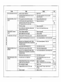
Troublt
Th~ sam(' nccd\c doc~
Remedy
OriP,
···- ..
not come out
I. Replue needle
2. l.th-right mea$Urt:menl probkm bet'\lt--een ro tary c:am
2. Correct ri&ht-ldt adjuSimcnt o( rotary cam (needle
~leclion
lcvn and rotary cam
Unnct;asary ntedles
6c)'<lo
C't>mt
oul al
The N.S.P. opaa1ioo
I. ' ll'lttt is grease betwa:n the n~le selector plate:$,
- :-·· "
is squeezed between the
opct:nion le\'tr presstr and the rotary cam holder body
N.S.P. uptf1otion 1c>u docs not moV<: easily.
2.
Knittin3 needle nut Klcctc:d a1
~<vet
mecban,$ffl)
I . Wipe arauc off needle sel«tOt pfatt..
2.
! ...
1'.37
~
Rcplocc koiuina .-lit
3.
Needle bent or brokrn
),
4.
Hook of n«dle ""lector plate spring is malting contact
with Olhcr nocdk select<>< p1at<s
4. Cnrrcct to hook the .-II< sel<c101 spring
I. The bun
0< shank of
I.
Replace kni!ling needle
6 cycles
n«dle bent
2. Holes in n«dle bed worn and enlarged
~o
l. The r Olaty cam lever- remains at lower pasi1icm.
I.
2. The pos.ition of card teadef' &Uide plate as100 muc-h tu the:
2. Correa horitontal adjus1mem of c:.ard readet ~uide plate
-
needle ""lee! ion in 121h cydc
c
,g
l
- -
2. Rep!.."< ncedk: bed
LubrtC:;ate the card mtdct IUidc plate
left
J.
.!!
1
z
..
~
Un.nooessaty needle~ cmne ()UI. at
12111 cyck:l<
. ....
Needle S<lection position is off by
12 slitthcs.
ROlaty cam is out of odjm;tm.:nt horizon lolly. Stedk
sck:caor plate travel is coo shon (Rotary cam ls positioned
too mocll 1o the right.)
.. .
Needle selector so&enoid remains power on.
-- -~···
- ·-
Soo P.42
eR>
4. Check needle select"" wlcnoid
).
3. Check needle >elcctO< solenoid
'
Needle r.t.lett0t Solenoid remains pl)Wer OfT.
-
I. The pOs-ition semor ts out of adjustment
I.
·~· '
mounting
carriage forward travel o pening is b ad
3. Bdl conncc:ting hote is damaged
4,
.
.
S. Slit diJ(' i.s damaged
.
...
adju.~tment
po~iuon
.
of positi<ln srnst'Jr aod
-.
Replace the cnnnectin1 plate.
Replace tt.e hell rulley brake (FriC1inn plat< spring)
3. Replact tM bell
--
Carriagt; and be-lt Stnsor <.itcuiuy system is bad
r:--·
~ ----- ·--
'
2.
4. Rcplac::t the encoder PC hoard or replace the main
PC boat~
.. . ·--
s.
- 3-
P.l l. 12
l.ubf'leate 1he ea1d ruder &Uide plAte
I. Correct \'illlage
-2. -
SccP.42
3. Corr«l hori1.untal »djuslmcnt of roc&ry co~~m
2. Corrttt h.or,tontal ftdjustment of card reader guide pl:ue
Conntetion between hclt a nd carriage cxm necling plate at
!
·-
I. T ht rotary cam leve-r rem.a.tn.~ at upper' position
2. RotKry cam is out of adjustment horizontally. Needle
se\cclor plate travel is too large (kotaf)' cam is positio1•ed
loo much to the left.)
'-:--·
S<t P.42
;s..P.36.
Rcplaa nttdl< seleclo.- unh
.. ..
Noces
. -·--
" --···
I. The bun or sJlank of necdk: bent
Repbcc eM ~lit d •sc
See P.42
c-:-
P.ll. 12
·-
S<t 1'.8
-
See
P.21. 23
Sec P.40
P.IS
-
4. NOTES OF CAUSION FOR CHECKING AND REPAIR
In order to avoid secondary damage, please pay attenlion to the
following points;
(I) When assen;bling. M disas.embling tbe machine, always ensure that t he AC
adapter is unplug&>cd from the socket.
(2) Be sure not t o pull the plug by the co•·d when disconoecting it from the
socket.
(3) Tighten nuts and screws down securely.
(4) llc sure not to lose any nuts, screws, or washers, and ensure not to leave any
of them in the machine during a.5i'i.cmhly. These can be the cau.~c nf short~ in
the electrical circuitry.
(5) J)o not damage the cords or PC boards with the soldering iron.
(6) The electrical pans w.;cd in the machine can be damaged hy static electricity.
T herefore, be sure to handle PC boards by the edges and to refrain fro m
allowing your hands to come into direct contact with parts.
(7) When tran.~porting PC boards, it is best to wrap them in aluminum foil or in
~:~n anti static elcctri<.:ity bag. \\'hen transporting the main PC board
assembly. always ensure t hat the lithium battery has been removed. Never
wrap the assembly with the lithium battery still anachcd. Polyethylene and
styrene can cause static electricity and should not be used fo r wrapping.
(8) Alier the completion of assembly or disa.o;sembly. check to en,ure that all
connector.~ a rc properly connected and that the equipment operate.~ normaUy.
(9) "Inc main power should be the same as the rating of the ma~-hine.
( 10) Ensure that the posith•e and negative terminals of the lithium battery arc not
shorted.
(I I) Check the exclusi••e adapter for knitting machine.
Clf it is used different adapter. knitting machine is broken.)
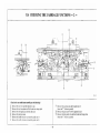
-· 4 -
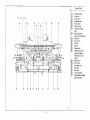
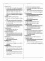
CIRCUITRY CONFIGURATION
I
I
I dt ptll)ltron llofr~
..... .......,
..
I
F,tK\')t,j"' P("' ~·ll
I
~if~'t!;~ilion toef'I'Or
I
S\Jk:IIOi<J PC' biJIUd
-
C. (..........
I
,., J t···
!
; T ,;:;;, ~
I•C':."'tl'IJ~'
The V, (pin 4 or PJ).
ligun: S-2 bcluw.
v, !pin 3 of P3) signal< 3r< cnnfogurcd a.< <ho•m
in
('ooutll PC"
Pl
""
N . J'5
l:!o>.:atd ll~l'llbb·
v!
;--:--,
n
_j : 1_1
M<tin Pl'
bo."trd 11s.scmbl~·
_ruu ··u L .
VI
Ill' lu~'4.
r
A.( ·. ~•J:tptcr
n
LJ
IIK:u i)\'1
10\\'W\'t
n
HI(;H I SV)
LJ : L_ "" ..
., I.OWI('IVJ
I
n_r lJ--L L
VI __
VI
5.1 Control PC Board
~ ···
- ·_n__r:u.
.
.
; _
-
:
HJ(III t)V)
L,(l\\' ttiV.
HIGH \)VJ
I .OW (0\o)
O..oml<
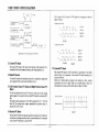
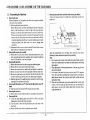
The control PC board is the main control ponion or the equipment. It is
comprised of the microcomputer. nttmory. and voltage regulator. etc.
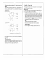
5.5 Solenoid P C Board
The solenoid PC board is a PC board which is acted upon by the needle
selrttor device. It is connected to the co ntrol PC board assembly by a
connector (P4, P5).
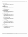
There are 12 needle selector solenoids, with numbers on them, counted
sequentially from left to right. T here are 6 needle selector plates, the
relationship to the rotary cam of which is given in ligore 5-3 below.
5.2 Main P C Board
The main PC board is the keyboard portion. It is comprised the lamp (LED
and 7 segment LED), switch, and solenoid driver, etc.
5.3 Left Position Sensor PC Board and Right Position Sensor PC
Board
The left and right position sensor PC board ar~; what send out the carr,age
position signal. lt is connected to the control PC board by a connector ( P2,
ltvuu )' ~·n• "''le'""'C.
P6).
I
The position sensor signal (pin 3 of P2. P6) is normally DC 1.6 - I.SV, but
when the K carriage sensor magnet approach.,. the position sensor, it
becomes DC 3.SV o r more.
l't«d~ 'C.'kckx pU&..~
z
3
4
_L'l_j _:_l 1
s
6
5.4 Encoder PC Board
.,i f!otu•:\-.,
The encoder PC board emits signals required in the dcte<tion of the direction
and amount o f carriage movement and in solenoid selection. It is connected
to the contml PC board by a connector (P 3).
-5-
e1
I
I
II
I
ll
·'··
.
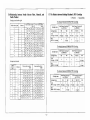
5. 7 The Relation between Knitting Machine & PI'D Cartridge
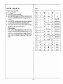
5.6 Relationship bet.,.·een Needle Selector Plate, Solenoid, and
Needle Number
0 Possible
Carriage ''"""llo 1h<: right
The relation between KH270 & PRO Cartridge
SccdJc l'Cle~;lur plate
SolenOid
I
I
2
2
J
4
24
47
l~
2l
)
.....
.14
22
4
45
H
,\2
21
20
J9
18
17
16
I
7
8
9
10
2
'
4
5
56
55
44
(k(l)
54
·~
42
)I
. 53
41
2Y
52
oiO
51
>•
28
27
50
49
If
•
numbct5
.16
5
6
)
Ydlu~ nr~k
...
1---· s
1--- 6
12
.~ I
·" ' , 26
l1!2S
12
II
10
9
M
7
6
l
4
IS
)
14
1.1
2
I
·-
(irttn nttdk numbtrs.
(ri.s,htl
I
1.1
2
14
3
4
15
)6
5
6
17
18
19
7
8
9
10
10
II
12
21
2:2
Cattrld&c fl31'llC'
2s I .17
·~
26 ! 38 . ~
l.oact
~~
5)
\~trtnt'lgc-
42
54
K H'270 - (.'11rtridgc:
43
55
45
~
28
29
.lO
Jl
32
JJ
..
J4
46
n
)5
47
24
J6
48
(16 p0£<S)
!)1we
Caruid,e Aa.tn(
·-
C...Odr: MC<~r1 ridJt
Soknoid
liC'IcC1or
pl31t
I
I
2
2
)
J
4
4
5
.I
tkn)
(righ•)
I s•
42
41
30
_ , 52
40
28
51
JY
so '
38
37
27
26
-
5.\
49
29
l
J
&
•
10
5
II
:56
25
41! • 36 24
47 JS 2)
46 J4 . 22
45 )) ll
44 32 20
6
12
55
43
~
1--·-I
6
:
7
-
9
)I
19
18
17
16
6
5
15
14
I)
'"
32
4
9
l
2
I
10
Jl
J4
JS
J6
II
. ..
9
8
1
31
20
12
10
;
R
..
43
..
• XHCJOO
12
I
l
3
13
25
37 49
14
L(>
)$
50
IS
27
)9
•5
16
11
28
l9
.10
40
51
52
41
42
S4
ll
6
I"
KH900 - ('"'ridJ<
P•~r)
0
( I Pi1J:,~t: l
0
0
X
( I P"!«l
t8
p:tg_l'\)
X
(for
S111t:h .,.&Item C• rtridgr Ill
(Cur PP0120)
rro 1101
..
940;271)
930
'140
910
X
X
X
X
X
X
X
X
000
v
(K pages)
0
(8 pag~: )
The relation belw~n KH940 & PPI) ('Qrtridge
55
56
45
21
2:2
2J
24
(I
0
(I (I ('ij\C\1
Stitch Pattern CmridgJ: Jl
s...
Grctn n«dk numhe~
0
P'i<l
'ICXI
The rdation between I( H900 &. PPD Cartridge
1--
YeU&.'IVt n«<fle number~
(I
0
X
m :z'o
930
..
0
KH2i0
(for PP01 20)
'140
9JQ
40
41
39
~liCclt Pattern C artrid~ Ill
(for PPDIIII)
Cttnnt.lgc Mode
51
27
I Stitc-h Panem Cartc,d~t ((
l...t
'IImile
X impossibility
<.:amkl~ name
46
47
48
~nridg,c ~oc.Je
l.oad
VVII • ("ornid"' • Kll940
S•"e
Klt940 • PPSl t Ctruidp:c
5~
- 6-
St;.ch Panetn Canridgr: II
Stilch l'attew Canridge Ill
(for PPI)II(J)
(for PPD I211)
930
0
(16p>g<<)
X
'140
c
(I r•S<l
0
(I pagcl
....
'
930
94012'0
9<)0
0
0
(I pag<)
0
H:l J'UilCO.:)
( I ~ PI&'')
X
()
( I poge)
X
Stitch Pattern Can,·idge EXTRA's
(Built-in 853 ratterns Option)
..
KH model
l.oo.d
___
KH~
,,, ,
0
. ···-·
KH270
KH900
(Canrl4g<- KH)
(32 P"8"')
• wtth PPD
0
(32 P"8")
(32 POI\CS)
0
Saw
(KH- C.r!tidg<)
X
X
X
• Remarks
1. KH940 cao n<~t kf'it rniXH.trcd pauerns. (Tuck & Loce pattcrns ! Wo~-e n-btoc
2. KH270 C.'ln n(ll ">nit mjxt~.~red p.auern and Jaoe patterns.
pilltcrn~)
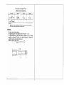
S.S Power
The power uses exclusive adapter.
The generating power of the adapter is DC7.5V and lA- 1.2A.
The generating power of the adapter which is changed into SV by voltage
regulator in tbe main PC board of the knitting machine, is supplyed to
computer. memory, and solenoid driver, etc.
Polarity of the DC plug; outside
(+)
inside
(-)
(+)
I)
- 7-
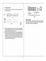
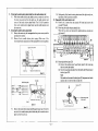
6. TEST PROGRAMS
6.1 Test 8RS ..... Needle Position Oetect Orcuit Test
G!Uii::N, and START lamps will be turned off. Then. the ~t ep 2 test will
begin.
*When th...., is a problem
By performing the checks given above, c heck the mounting position of the
position sensor PC board hoti7.0ntally and venically to sec that each have the
proper voltages. If they do not, replace the position sensor PC board.
• Step 2 -This is to check to sec whether, of the needle position de tect circuit
signals, the v,, V;, and iRQ (count edge) signals have been properly
sent lO the computer.
( 10) Move the carriage forward and back ward one time (20 needle-< or more). If
a problem is noted during step 2, an "E" will be displayed in the memo
display, and an e rror digit in the display. When there is an error d igit in the
displar, the
will proceed no funher.
If the STEP key i$ pressed. the step 2 te$t will be repeated.
• Step I -Display right or left position signal voltage. The computer will repon
that it has detected either the K carriage sensor magnet.
• T..t procedure
(I)
(2)
(3)
(4)
·r urnthe power switch on.
Turn the display off by pushing the ICE I key.
Input the digits .:ID ®~and push the STEP I key.
The voljlfj oi the left position signal will be indicated in the d isplay (for
example, J 7 6 indicates 1.76V). A yellow lamp will light, indicating tl\at the
left side is being checked. When there is no carriage sensor magnet in from of
the sensot, a voltage of 1.76V or 1.92V will be indicated. At this point, if the
VR on the left position sensor PC board is turned, the voltage displayed in
the display will also change.
•Note:
In the event t hat the voltage displayed in the di,play does not fall between
1.76V and 1.92V, adjust via the VR on the left pusition sensor PC board.
This adjustment should he done a< follows: first , turn the VR slowly until
1.92V is displayed, then turn it slowly to the left until 1.76V is di~played and
stop.
*Wbeo therr is a problem
When adju8tmcnt cannot be effected, replace the positio n sensor PC board
srp
F.rror digil ba.< error digit "F.Y only in this step.
E3! the v,, v, signals or iRQ signal are not sent correctly to the Main
P.C. hoard a"embly when the carriage is moving.
When other than "t:J"
The condition of the v,,
v, signals will be indicated in a 3 digit display.
0: proper condition.
I: The signal remains High
2: The signal remains Low
and attempt the abo\·e adjustment again.
(5) Place the K carriage sensor magnet in front of the sensor (with the change
knob o n < KC>). At this t ime, the voltage. indicated in the display should be
3.36 V or over. When voltage is 3.tl4V or over and the computer detects th~ K
carriage, a "I" will be di.,played in the memo display.
If the direction of carriage movement changes (from right to left (when the
yellow lamp is on), it will turn oll'. Check the both of sensor magnet.
(6) Push the IGR F. F..NI key.
The voltage of the right position sensor signal will be displayed. The green
lamp will light indicating that the right side is being chec~ed.
(7) Using the sequence given in (4)-(5) above, check the conditions of the K
carriage on the left.
*NOie:
To recheck the left side, pushing the [.yr:Li.OW] key will put the equipment
tn the condhion given in (4) above.
When there is no proble.m by performing the checks given above. Push the
I~TEPI key. and the voltage <lispla)· un t he <lispla)• well "' t he YELLOW,
- 8-
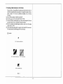
6.3 Test 888 ..... Memory Test
•Whenthcrt is • probkm (rhc c.o ndition of V,. V, i ignals is indicoted in Ihe
displays.)
After 1he check is completed. if 1he condit ion of V1, V:: signals is indicated in
the displays. replace the encoder PC board. then perfo rm the dleCk again
starting with ste~). I.
C:unxl!" lr:••:.-l:nv l it l ilt- Ti~h1
~
4,; "'I>Ol'(
The computer wiiJ test the memory. The c xccwion of th~s test 'A·ill cle:ar the
mcm(HY of the entirety of its contents .
• T ""' procedure
.
Turn the power switch on and t urn the dj~lay nff l>y pushing the [cF.[ key.
G) Input t he digits ~ ~ IEf and push t he [S'rE~ key.
55 ( H F. X) will be written into all memory field s and a check will be
performed tn ensure that 55 ha< hccn written. Then. 11./\ ( H F.X) will be
written, and a check perfo rmed to sec that 11.11. has been written into all fields.
When these checks arc passed. a 0 is: written into aJI Jie1ds of the memory anc1
t he READY lamp lights. If the checks are not passed. an "E" will ind icate in
t he memo display. Pushing the 'STEPI button repeats t his test.
*Note
<D
~
Vl__j!~,
v' ~
l ~•w tOV)
The check rt:quires about 30 seconds for completion.
Be sure not to turn the power switch off before it is completed.
~
4 ..Sm~
- ;
VI ~
*If there is a problem
If an error is registered on the d isplay, replace the main PC board.
l m'o'(IN I
V!~
·.. ..: ~ ~
ll
t>
If no problems arc notcc.J in su~.p 2. a bua'i!r \Vill :;oond, and the READY
lamp will light.
• When there i-s ot probltm
After the check is t'omplctcd, if t he READY lamp does not light. o r if an
e.rror d igits is not indicated , repJace the encoder PC board. After
replacement perform the check again starting with step one.
- 9-
6.4 Tc~1 889 •.... Display Key Test
Chart 2
• Sttp I - Indicator lamps all blink.
(1) Turn the power switch on.
f'ush the [1] key. turning the d isplay off.
Q) Input the digits ~J [ID ~- a~d,_push the JSTEPi key. In the d isplay and in the
memo display window ij 1~1 ~1 and liD. and the remaining lamps ( L EDs) will
all light on.
@) Pres" he STEP I key. T he di~play and the lamps will all go off, and the step 2
tt-,;t is ready. Check to ensure that the keys are functioning properly.
(?) If a key is pushed, the numhcr for that key should be display«! in the d isplay.
The numlx:rs fo r each of the keys is given in chart 2.
*If there is a problem
T here is a problem in either the main PC board or in the co ntrol PC hoard.
Replacing the main PC board and repeat the "889" test program. If the same
problem reoccurs. that will indicate that there is a problem in the control PC
t>oard, so replace it. l n this event, the former main PC board should he
(ndi<:U·
a)
20
0
21
I
22
23 .
24
25
26
2
28
--·29
30
- 10-
34 ..
35
l
4
5
6
7
.
·-
:
-···-· .
_Green
______
CE
90
VA RI AT IO~
37
M key
91
VA RIATl0:-12
c
92
VA IUATIO~
39
···SELECTOR I
93
94
VA RIATI0'4 3
· ···-· ··- VA RIATI0'4 4
95
VAR IATI0'4 6
96
V A RIATI0:-1 7
50
' 51
·- ··
Yellow
,
lNPt;T
-u((, [)__ _
CHtCK
.... ....
MEMO
,,
'
56
I
57
0
•..
· --·
__ ·-·- ··- ··- ·
97
98
I 55
I
···--
\1
STEP
32
•
36
·- +·-52···
9
i 53
CR
58
,
Key
- ---
SELECfOR 2
8
'
....
59
...
38
J
httJic.:ation
Key
e:.
---
:
3
31
33
.
'
27
normal.
Indica
(i..,n
Key
tion
99
43
45
I
5
----
..
R
---·-·
s
-··-··START
LOAD
·-------.
SAVE
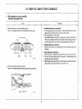
CHECKING THE NEEDLE SELECTOR
- - - - - - - - - - - - - - - - - - - - - - - - . , - - - - - - - - - - - - - - - - - --··..·····---·-·-------,
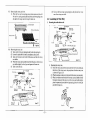
7.1 Checking with the Power Switch Turned
CD
\6)
orr
7.3 Checking with the Solenoid On
CD
Remove the two uper~tion panel s<rcws. While holding up the left side of the
panel and sliding t~ panel toward the le ft . remove it from the main body
with connectors on.
(•Place the removed panel on the rear of the main l>ody case.)
@ Remove the three cord C()ver screws and the cord cover.
(j) Set the K carriage needle cha nge knob to < KC>, and pu t all the needles in
position A.
@ Turn the power switch on, and push the §!'M<iJ key (as in 7.2 ~~).
~ Move the K carriage past the tum mark from the outside, and then move it
from right to left. The armatures should all remain in the down position.
Set the K carriage change kn<>b to <K<.> . and put all (>f the needles in
position B.
Turn the power switch off, and move the K carriage to chL-ck all, t he needles
should be selected to position D.
•Not~
The above check should be performed with the carriage t raveling right, left,
and at high speed and at low speed.
•u mere b a probltm
T~n it will be in the needle selector mechanism of the main body or in the
carriage needle selector mechanism.
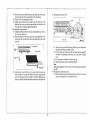
7.2 Checking with the Power Switch Turned On
CD
Set the K carriage change knoh to < KC>, and put all of the needles in
position B. ·
Q) Turn the power switch on, and push the I.MJ!.~<!I key. T~ IMEMOikey
lamp should light.
•N.,te;
7
If t~ 'r:~-=
~@
M"'o"' key lamp does not light when t he :~.QJ key is pushed,
tum the pattern number lamp on after turning the selector ( l) key on by
pushing the ISTEPI key. lnpu~ pattel number 100 (or any oft he others from
1-238 or 881·884), push the STEP key twice, and push the IMEMO! key
once again when the READY lamp comes on.
(j) Select needles after the K carriage has passed the turn mark from the outside.
At this point, the needles should all be sele<..~ed to p<><;ition 8.
Pltl\lt~t 1·1
·~ote:
The above check should be performed with the carriage traveling right, left.
and at high ~peed and a t low speed.
is • problem
tr there are needles selected to position D. perform the check given in 7.3.
•u a problem is found in the 7.2 clteck
•(f then
If a problem is found during the 7.2 check but the 7.3 c~ck produoed none, it
will indicate a problem i n either the needle selector mechanism of the main
body or in the carriage needle selector mechanism (.-efer to 13 on P.42 and
11.3 on 1'.2!J.).
•11 a problem is found in tbe 7.3 check
II will indicate a problem in the electrical circuitry. Check this with t he test
program given in chapter 6 (KK5. 8&8). If this does not produoe the answer.
perform t he check in 7.4 (the example shown in the picture is a soleno~d no.
"9• problem).
- II -
Sulcnuid P.C.8.
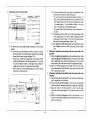
7.4
CD
Checking the Solenoid
Tum the power switch off, and disconnect connectors S4 and S5 (P4 and P5
on the main PC board).
N
sl)~..oi~o~
numb\''
PS
, , • ' ~ . I I•
s '
.r. 1
I• '
I I I l l I I I I I I I I I 2I I I ;I
•'•
' •
'•
v
" "v
2 ]
·I
4
9 10JIIl
Sl.'h:fU\i(:l
nu111b:.:1 t.)l)
the jO!CllOid
t't' bi>:ird
•
(:ullar•i lhl.·
lt&l 61)!
'1' 8\\' R\'
10 I I l2 ;.1 1-' I S 16
BWR
• 9
(\
...,.,.J
I
I
2
3
'
s
6
•u lh«e is a problem
If a problem is found in a check between the solenoid coil and the solenoid
cha.<Sis, replace the solonoid. If a problem L< fo und when checking the
snJcno'd signal cord, replace the solenoid signal cord.
1 i
WR YU W M YBWR
Y
a
'IN
\'~ll;)w
8lu(
Whi~o:
R Red
G) Resistance should be within 100- 123 n.. If it is not, there is a problem. which
Q)
may be found with the check given below. If no problem is found in the
resistance value~. perform the check given in 7.5.
Disconnect the needle selector solenoid unit. Check til<' resistance values of
the places which correspond to the solenoids o n the solenoid PC board which
were found to be bad. The resistance value of the solenoid coil should
between 100 - I 23
the resistance value of the solenoid signal cord should
be 0, and the resistance value of the metal portion of the mai.n body and the
solenoid should
~n (refer to figure 7-3).
n.,
oc
oc
12
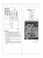
7.5 Checking :-.leedle Selection hy Test Pattern
Pattern numbe•~ I t hrough 288 are i111ernalized. but other than that, there are
also 881 1hrough 884 which are teSI pallerns. The pattern fo r each o r these. is
glvcn in figure 74. The test is performed ac.:ording w the fl,llowing
procedure.
(I) Put a sufficient numher o f needles in position ll
G) Turn t he power switch on and push t he selector (I) key.
@ Push the STEP key. and then the CE key. Then. enter the digits 88 1·884, and
push the STEP key twice. The READY lamp sho uld light.
@) Turn the variation (4) (double length) switch o n, and s<:l the K carriage
change knob on < KC> .
(~ Sclcc1 needles after passing Ute K carriage from the outside of the turn mark.
The needle selection should change af'rer every other pass.
Q
Tt:~lplltl~rm
•
•
- u-
8. CHECKING THE A.C. ADAPTER
KH-270 i~. uses cxcluswc A.l. adaJllCr.
As the O.C. output c>f the cxclu~ivc A.C. adapter Ls 9.5V .... l4V in no rcs~stanc~:.
Jollow the test procedure:
• Test Pn~tdun
(l) Turn off the powers witch of the l<nitting marhinc. Pull oul lhc A.C. adaplcr
from the knilling machine and the outlet.
{2) Check t hat the \•Oitagc of thc outlet is within +I (I% of the rated input \·Oitage.
(If it is less than - IO<!i of t he rdtc-d input "oltagc, t he knitling machine can not
work. lfn i~ more I ham+ J()(j; 01 the rated mput voltagt.thc: knitting machine
and tho A.C. adapter may run hot and thi, is dang<-rous.)
(3) If tho voltage of the outlet appropriate. plug the A. C. adapter into the
outl<t and cheek that the D.C. output is 9..5V - 14V.
THkc: nne not to mL'<handlc the plu.s: and mmus temunab or the tester. {and
L'
nolto ~hortc.in:uil ahem.)
""-
• lithe U.C. out putts not 9.SV - 1.N, replace the A. C. adapter "'i th the new
nne.
-1 4 -
REMOVING ELECTRICAL/ELECTRONIC PARTS AND PC BOARDS
1. Removin1 the battery and Control P.C. Board
<D
On removin&the Con~rol PC board, do not give a force on the radiate heat
board.
Please, try to run TEST PROGRAM ·~gg• in order to clear the memory
( RAM I after assembling the pattern ca.<e whole unit.
Rcmovillgthe Pattern case whole unit after removing the adapter.
q) Disconnect aU S of the connectors of tbe Control PC board and Main PC
board (P2, P3, P4, PS, P6).
Cl.) Removing the three screws of the Control PC board . (Figure 9- 1)
@ Disconnect the Control PC board fro m the Main PC board as raise it
horizontally. (Remove the P7 and S7)
(5) Dissolve the solder on the lead of the battery with a solder iron, so remove
the battery.
•CAUTION
Pay attention to be hot the radiate heat board soon afler power off.
2. Removin&the Main P.C. Board
Q) After remove the Control PC board, remove the eight screws of the Main PC
board.
Q) In order to remove the screws, remo\'t the Main PC board and Keys, so
inven the paucm case ~~o·ho~ uotit .
-15 -
10. WH EN CREATED PATTERN DISAPPEAR WITH POWER SWITCH ON
••E" blln~!O in the memo display and the crealtd pallc:m d~!<oappcars wht:n entering
crcmed pattern.
lnahi, •~•><'. I he ballery is con.,umed up !he •olau~;c i> dropped less than OC 2.5V).
Or. thert is romething damage in the memory cSRAM) for created pantro. So
that. ~htck bolh the bancry and the main P.C. bo"rd ac-.:ording to following
'IC(l>.
• Note
In ca~t of Kll-2i0. if the battery is consumed up. 0 1', •here is ~orne dameigc.~ ln 1ht:
($R AM) which is cleared automatic;olly wit hout ~linking of "'8!\8".
And lf power switch t)ff or disconnct:t the cunr~d,ge whilt" i'i road from cartridt;l'.
mtlll\>1")'
che lllt!lllOry is t:lcan.:.d automatically.
( I ) Kemov<· I he Main PC hoard. Then naeasua·e Ihe llC vohage between
terminals of the battery w•th a ctrc\lit tester,
\2) If the voltage or battery;, b > Ihan f) (." 2.S(V). the haucry is OUI of order. So
rcplal'e the battery.
II the nlltagc of the bancry is 0{' 2.5(V) or more. the ba11ery is no rmal.
Then. try lhc TEST PROGRA M
lor cht.:kinx the memory ( RAM)
circuit of created pallern. If ··F." ;, inrlicaacd in the memo display. thert is
pro~lem on the memory circoit'"' rcplucc the Control
board.
·ssa·
rc
l.
·- 16 -
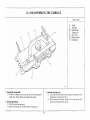
11.1 OISASSF.MBUNG THE CARRIAGE
:"'omts ul Parts
"D
~-1
~~-I
Q:l-2
(3)-3
II au<lk
Stilrh d ial
Stitch dial Cop
C:.11rriagt: cover
II. L.C. kno b
Plain le;·er knuh
Chnn~e knob
Il l,:! 1:
I. Romovin& lhr a~rriag• ""nrtk
1.1
J. Rtnto"·ina tht cnrix'" l"U\o'tr
.ll l.oosen and remtl\'1!' hoth right cmd k:ft carriaJ!C rover chtmp screws from
Remove both handle screws o n right and ldl sKks while keeping the
handle down. lben the handle can be t aken orr lhc carriage.
tht bon om uf the carriage. (Sec Fig. 4)
.::arria~"< .-uwr upw•r<l. Then t he H.C I . k nob. Ilk! plain 1.,,..,..
knoh on<! the ~:h onge knob. will rome olt
3.2 Remove
l . Romuvingthe stitch dial
2. 1 Pull o ff the <t itch dial cap urward.
2.2 Romove t he fas tening screw and pu ll orr the >told• dial upward.
- 17 -
Names of Parts
Cam buuon unit
Raising cam ehange spring
@ ·I
I
Knit leader tripper
I
Row counter tripper
('[)
...
I
I
I
Q
lo
Q
'\,.!t'
I
0
D
Q
I
~~<O!~
''
\_/
,
·~
I
II
I
(~)
4. Removing the cam button unit
4.1 Remove the right and left raising cam change springs from the raising
0
I
I
I
I
/
0
IJ)!I
0
I
Handle setting base
•-screw 3.57 x 4
(For handle Joe~ spring)
Upper slide plate assembly
r
I
I
\
(b)-1
6. Remo.ing the handle setting base
6.1 loosen the right and left screws to remove both handle lock springs.
6.2 Remove screws on both sides to detach the handle setting base.
cam calking pin"' with the work hook$.
Remove two screws which clamp the cam buuon unit.
4. 3 Remove the cam bunon unit by pulling it iorw•rd and lifting it up.
4,2
S.
7. Rtmoving the upper slide plat•
7. I Re.move the s11ap rings for the change knob shaft and the carriage
ca lking shaft which is located on the left side with a slotted screwdri\'er.
7.2 Rcmnvc th<.; upper slide plaic tly lifting up it ~ hoth ;;;ides simultanel)usly.
IMmovi.ng th e knlll~adtr tripper and lbt ro.,· counttr tripper
5. I Remove e<ldl two :..crew~ damping th~ knit le-ader tripper and the row
~t)I.Hnec tr ipper from the bon . .Hu of the ~~H riag.e.
-18-
8.
R<~T~uvinc
the netdle selection chan~• l•><r •l)ring
Remo"" the right and left needle selection change le•er springs from the
carriage rear plate.
8.2 Pull up and remove the right and lei\ magnet holder.
Removinc the ronnectint plate spring
9.1 Pull up and rcmo\'C the right and left connecting plate spring.
Rernovinc the reu plate
10. 1 Pull up and remove the rear plate.
Removlnc the tude cam operating plate
11 . 1 Remove two tuck cam springs from c•Jking pins.
11 .2 Pull up and remove the presser ring and the right and left tuck cam
operating plates.
Remu>ing the chance plote A and 8
12. 1 Remove the right and left MC cam springs from the pin.
12.2 Re move the change plate spring from the c hange plate.
12.3 Remove the change plate A spring from t he change plate.
12.4 Remo\'e the change plate 8 spring.
12.5 Remove the nut of change plate guide collar 111ith a 6 m ! m box d river
to detach the change plate guide collor.
12.6 l'ull up and remo\<e the change plate A and B.
RtmO•ing the push-up chance plak
13. 1 Remove the screws of pU$h-up c hange p lates, right and left , and also
the eolian placed under them.
13.2 Pull up and remove boUt push-up .-hange plates.
Removina tbe cam ehanc~ plate
14. I Remove the valve camE spring.< from the cnrri•ge ca lking pin and the
valve cam E.
14.2 Remove the right and lcli cam c hange pla tes by loosening and
8.1
'·
I G.
11.
11.
13.
14.
removing their nuts.
15. Removinc the valve cam F 9prirtg
15. 1 Remove both valve cam F sprinS$ from the selection guide for right and
left end needles.
16. Removlnc th• nut
16. 1 Remove both nuts from the front side of carri•gc.
-(9 -
Names of Parts
.~
@ ·I
...
-~
~[l - 1
Need le selectio ,
le,•er spring n <hange
·~•9 '
Connect'
Rear 1 mg plate spring
..
pate
1uc.k cam operating plat
Chan
~
.
..-
®
I
I
-3 Ch ge plate spring
-4 Change plate A spring
I' ~nge. plate B spring
ush-up ch
-I Push
ange plate
clam~~~ ~han&ge plate
.
C
. r w collar
' -I .am chanKe plate
.
I
§
.
I
H
'
'.~k
··"'
['..
0
0
0
I
0
a·_p
0_./) )
;
/
/
@
''
i
g ..,
\
I
I
Q~ ·1
6!;
I
·!IP ,,
l{]l ··'
II}
l(i) ,,
~
20
Valve camE
-2 Cam ch
spring
Val
ange plate
• · ve cam F spring
·
(
Change plate A (upper)!
~j -2 Change plate B (lower)
t'Ut
17. Removint the front slid< plate
17. 1 Remove Ihe right nod left saews to pull up and remove the rront slide
plate, then the holding cam sprinJ;> com.: off the l'ront side.
26. R emoving the ~1 (. cam
26 I Remo\'e bvt ll rixht und Jcfl :-A C cams by removing the ;,~rtw'> on (he-
( Rc sure ttl sec the H.C'.l. knob to II position when pulling up the
plate.)
Removin ~ the cani~t• front foot
18. 1 Remove two screws to detach the carria1,~ front fool.
R tmo•in&t he &ui<k <am A
19.1 Re move t he right and left screws to dctHch the guide cam A, and the
slid e ca m comes off.
Rm~ovin1 the slide 10id• am assembly
20. 1 Remove two nu ts of the slide guide cam scr<w from the fron t side of
carri"J!". then remove the slide guide cam assembly by loosening two
clamp screws.
Remo•in1 the pu<b-i~p com
21.1 Remove the right and left sc.-ews, which damp the push-up cam, from
the front side of carriage.
21.2 Then the push-up cams and the push-up cam holder plates come off.
(At the same time. r<mrwc the push-up cam guide.)
Removing the M C guide cam
22. 1 Remove both .ct-ew• on right and left sides, then the MC guide cams,
the MC guide chan~e cnm;, and the shafts come off.
Rem u•ing the tbrt~d·lace chance plate
23.1 Remove two screws of the fa.tening plate for threlld-lac" change plate.
23.2 Loosen two screws of the rear foot.
23.3 Pull up and remove the thread-lace change plate.
Remtnlng the s titch cam
24. 1 Remove the right and left snap rings o f the stitch cam s hafis from the
27. R emoring the s titch <OIII gul<k plate
27. 1 Remove the sMp rin~s and the washers from tlte shaft to detach the
; titeh e;om guidc plate.
28. Removing tbe Julde cam •·
28.1 Re move both right and left guide cam J-'s by detaching their screws.
29. Rem o•in~ t he needle .sdtction cam
29.1 Remove the guide earn Gs by detaching their :screws with a small
r hillips screwdriver.
29.2 Remove the scn:ws of nc<:dlt select ion cam, then the needle selection
cams, the ne«<le ~lcttio n cam guide plau:s. and t he needle seleelion
change cams come off.
29.3 And remove tbc nc<:dlc selt<.1ion change •paom; (collars) and the val'-e
cam Fs.
JG. Remo•inctho $tp40rltlon am •nd t he bull'. .- fur selecttd needle
30. 1 Remm·e the $Cr<Ws tO detach the >Cparation cams and the hulfers for
selected needle on both right and left sides.
31. R emovin&the tuclt cam
31.1 Remove the ;crews of tuck cam on both right and left <ides, then the
t uck cam pla te. the right a nd left luc k cams, the t uck cam ~prings, and
the tuck cam shafts come off.
.12. Remo•ing the carrieRe rur foot
32.1 Remove the selection 11uides for end needle fro m the front side of the
carriage and remove the e nd needle select ion sprlngs from the; carriah'C
plate.
32.2 Remove ~ix screws to d etach the rear foot.
32.3 And the selection earns for end needle, the end needle selection cam
• pri11g•. a11d t he ~election a uide; (or e nd nc..-dle come off.
33. Removing the conncctinc plate
33.1 Remove bo th right and left conneeting plates by pulling up the front
font side
34. Removinl the needle $election <hone• p!Jitr
34.1 Remove the clamp screws of needle selecuon change plates.
34.2 Re move the s haft s for ne(dle selectiM c hange CHm.
(See r arts Catalogue. part no . 154 on page J.)
18.
19.
20.
Zl.
22.
23.
24.
each side~.
front side.: of the carriuge.
24.2 Remove bo th nuts of s ub s titc h cams from the front >ide of the carriage
with a ho x dr\vcr.
24.3 Remove the screw of the s titch cam (left), chen the s ub stitch cam (left),
the >!itch cam (left). the valve cam 0 (le ft ), the valve cam 0 spring
(left), the s ub s titch cam shaft (collar), a nd the screw itself come off.
24.4 Remove the riuht stitch cam in the same way.
25. Removinc the valve com A
25. 1 Remove ~nth riaht and left valve cam ns by removing th~ screws on the
each sides.
- 21 -
Names of Pans
lj)
<.
Front slide plate
Front
foot
q~
Guide cam A
Slide guide cam
Push·up cam
:~~
MCguidccam
Thread-lace change
plate
~ - 1 Fll$tcning pla te for
th read-lace change plate
Stitch cam
Valve cam 1\
:-..!Ccam
Washer
·to:•'r :-~·· c .,.. f,., ,...,., ;;,;:~· , .a ..·•
@>
\
i
I
I
I
~·.}
;[j)
{>,)
I
I
I
I
I
I
I
I
I
Qj
•tt•..s
~
~
it
·3
tjj• · I
...
'
I
t»c
I
()
Guide cam F
Needle selection c.am
guide plate (upper)
Needle select ion cam
(lower)
Guide cam G
' c2 Valve cam F
Separation cam
Tuck cam
Rear foot
Connecting
plate
'
Needle selection change
plate clamp screw
$-1
$
·~.
'
I
I
I
I
I
I
Q)
I
~j>
C3
®
Q)
-I
-2
II
!'•
H
L-----------------------------------------------------------------------~---------------- 22 -
. ·--· · - · - · · - - - - - - - - - - - - - - - - - - - - - -- - - - ,
11.2 ASSEMBUNG THE CARRIA(;E
(~)-.t
(~.' ·'
\
Names of
1\'ecdk
I
Part~
sel~ti Ml
changr: pl<•t-::.
Sh.:.fl
I
Connc(.'ting plah'
I
R~ar f~)ut
Sclt-ction cam ioc Md nc:~Ht
Thrcad-,a<;f dmnge pl(ltc
'Jud •:a m
Needle s.clcc::tlon cam (low~:t)
Needle &d cctJ<Hi cotm goidt
plate (upper)
Rulltr for 1>dectcd net?dle
Scparati..)n cam
Guidtt cam Ci
Guid~c\tm
F
MCcam
VtJI ~~t•m A
S litch cam
Push up cam
Slide guide em'n
MC guide cam
Guide~am A
From fo-ot
4
Front s.liUc: pl;trt:
.J
·I
I. :1-lounting the needle selection ehaoge plate
I. I Mount the neodle selection change plate~ and clamp them wit h screws.
1.2 Mount the right and lcf! shafts.
a nd left selection cam.s fol' end needle, t!'l\d needle selection ~,vltc b cams.
and spring onto i1.
3.2 Hook the end needle selection springs over the selection guide~ for end
necdJc and the carriage plate .
2.
Mounting the connecting plate
2.1 Fit the conne<:tiug plates on the carriage plate.
(Take care not to confu.se t he right connecting plate wit h the left o ne.)
3. Mounting the rear loot
3.1 Mo unt both right and left selection guides fo r end needle onto the
carriage plate. Clamp the rear foo t with .~erews after putting t he right
4.
- 23 -·
Mounting the thread-lace cflangt plate
4.1 Put the thread-lace change plate bet ween the carriage plate and the rear
fooL
4.2 Clamp the fastening plate for thread-lace change plate with screws.
(Be.· sure to check the thrcad-laoc change plate movCO> smoothly.)
5.
Mounting the tiJCk cam
5.1 Let the right and left .crew< through holes of the tuck cam plate and
put t he right and left tuck cams, shafts for tuck cams and the tuck c am
spring; take care of t he proper direction of t he tuck cam spring. '!ben
clamp the t uck cam assembly o nto the carriage plate wit h screws.
(These t uck cams should be kept open, and sh<luld be ret urned to their
home position by the spring pressure when they arc prc.')Sed and
released.)
6. Mounring tht netdle stleclio>n cam and the separation cam
6. J Fit both buffers fo r selected need le into the square holes of the carriage
plate.
6.2 Put each separation cam and needle selection cam t ogether and moum
each needle selection cam guide plate onto needle seJectio11 cams. Fix
them respectively with screws.
63 Put t he valve cam Fs, the needle selection change spacers (collars), the
needle selection change cams, and the gukte cam Gs in thi_s orde•·. Then
assemble them with screws and a small Philtips scre\\,.drivcr.
7. Mounting the guide cam I'
7.1 Mount the tcft guide cam F and fix it with a screw.
7.2 Mount the right guide earn Fin the same way.
8. Mounting the Slit~h cam guide plate
~.I
Mount the stitch cam guide p late from t he front side of t he c arriage.
Then put wa.•hers to the right and left shafts of the stitch ca m guide
plate from the bottom side of the carriage and fix them with snap rings.
9. Mounting tbe M C cam
9.1 Tigh ten the screws of MC cams.
(Be sure to check these MC cams move lightly.)
10. ~lountinR the ••l•e ••m A
I 0.1 Tigh ten the screws of valve earn As.
(The vah•c cam A should be moved lightly by t he prcs:;urc of the va lve
cam 0 spring.)
II. MoWlting the stitch cam
11.1 Moum the left sub stitch cam shaft (collar), valve earn D spring, valve
cam D, Slitch cam, and sub stitch cam in this order onto the carriage
pla te. Assemble them with a screw and fix them with a nut from the
front side of the carriage.
(Be sure to set the valve cam D spring properly so t hat its str:•ighl end
may be placed over the bent part of the ' a lvc earn D and its c urved end
12.
13.
14.
15.
16.
17.
U\'l'r the vttlvc -:am A.}
24
11 .2 Assemble and mount the oight stitch earn in the same way.
11.3 Pur the snap rings t o the stitch earn shafts to fix them from the front
side o f the carriage.
(Be sure to check the va lve cam D and the stitch cam moves lightly and
the valve cam D is returned to its home position by the spring pressure.)
Mountin& the push-up <am
12.1 Put the push' up cam ho lder plates t o t he sliding grooves of each pushup cam. Then mount the right and left push-up cams.
12.2 Put both push-up cam slide plates from t he front side of the carriage
and fix lhem wirh screws.
(Rc sure to check the push-top cams move lightly.)
Mountine the slide euide cam
13.1 Mount the sl.ide guide cam and fuc it with two screws.
JJ.2 Tighten two nuts from the front side of the carriage.
Mountin& the MC guide cam
14. 1 Mount the shafts (collars), the MC guide change cams, the MC guide
cams onto the carriage in this order and fix them with screws.
(Be sure to check the MC guide change cam moves lightly.)
Moun6o& the guide earn A
15.1 Mount t he guide cam A and fix it witb screws on its both sides while
putting the slide cam into the floated part of the slide guide cam.
(:vtounting dimension fro m rear foot is 71 mm: See How to Adjust the
Carriage mentioned in this manual.)
Mountin& the front foot
16.1 Tighten the two screws in t he middle of the carriage front foot.
Mounting the fronl slide plate
17.1 Mount the frunt •lide plate onto the front fO<>t and fix them \\1th both
right and left stud screws orthe front foot.
(Be sure to check the slide p late moves lightly and the change cams
move d own when the slide plate is slided 10 the H (Holding) position.)
18. Muuntlu' cl>e <~"' ~bangt place
liS. I Mount ttnU £i~ t ht c:un cha nKt pla lt witlt nu ts.
1 ~.'2 H ook the valve cum F. spr'i llH'> vver l h<' carriage- calki ng pi n •'nd the
valve cam E.
19. Mounting u.. •·a.l•• cam F sprln&
19. 1 H oo~ the • •••• ( • rn r >prin~; over the selection guide fo r end ncL'<IIc
and the va lve t•am F on each side.
20. M ounti n1: the nul
20.1 Mount the nutS v.ic h box drh-er (6 m m).
21. Mountin' JJ\t pusll-..p ella"*• J)l•c•
21.1 Puc che screws of push·up cam slide places and che shafcs of :\1C guide
cams inco che holes of push· up change places. A u~ch che collars and fix
them with foetCWS .
22. Mo omtinR !he chanlt plait A ond 8
22.1 Moun! the chAnge place B and che change place /1 in this order. Tben
puc !he screw (change place guide collar) and fix !hem wich the nut (6
m! m).
'22.2 Hook t he cha nge pl01c .1pring tO t he lcfr.
22.3 Hook the change place /1 spring to the right.
22.4 Allach the change plate 8 ~pring hetwf<'n t he change plate B and the
thrcad·l&e< change place.
2.t Mounting lhr tuck c:a_m uperalinst pla te
23.1 Put !he tuck cam opera ting plate right. first omo the shaft or the stitch
d ial then puc t he tuck cam o pe rating plate left and the ~o!Jar O\'er them.
23.2 Hook bot h right and left lUCk cnm springs o ve r the calking pins of !he
' tuck cnms.
24. l\1ounling the carrias• rear plate
24. J Moun! the cMriage rear plate and hook !he ch•nge lc•·cr springs.
25. Mounting lh• conn«:ting plate •prin&
25.1 Hook chc righ t and left connecting plate springs over t he calking p ins of
co nncc:tin ~
rla.t..: and the shufl~ o f change knot>.
- 25 -
Names of Pans
~~
\
I
'(
·? ;
i
I
C1 c
,_
i}
'];;::,;~~
I
0
~··l
•I •." ;·:
----- ---~--
- 26 -
:'l,amcs o f Parts
·~
Upper slide plate
·~ -1 Magnet holder
' ... -I K nir-lcadcr tripper
• -2 Row counrcr tripper
Handle setting ba.o;c
-2 Handle lock spring
Cam button unil
-2 Raising cam change
spring
27. Mounting tht upper slide plate (Mountln& the IMJllltt bolder)
27. I Pur the two m~~gnct holders in the hoks of the carriage plate.
27.2 Mo unt the upper slide plate so that the calking pins of the carriage
pl•tc. the cunnecting plate pins, and the cam change plate pins, on both
right and left sides, come into six slots of tbe upper slide plate.
( Be sure to check the pins of needle selection lever are located before the
upper slide place.)
27.3 Fix the upper slide plate with snap rings on both right and left carriage
calking pin•.
28. Mount inc the knit-leader tripper and the row counter tripper
2M. I J'ur the knit-leader tripper on the left side and lix ir with two screws
from rhe carriage bortom.
28.2 Putrhe row counter tripper on the right side •nd Jix it in the same way.
29. Mounting tloe bandit settinc base
29.1 Hx the handle settina base~ with screws.
29.2 Fix the handle Jock sprin!l5 with screws.
30. Mounting lhe um bullo n unil
30.1 l'irthe cam bunon unirto rhe shafl of stitch dial and Jix it with screws
on hoth sides.
30.2 Pull up the right a.nd left raising cam change s~rings and hook them
over the cam calking pins while pushing "Part" buttons, righr and left.
(Be •urc to check the cams surely change when the buuon<. TI:CK
( Rj L), ~C. L, PART (R/ L), are pushed.)
-27-
Names of Parts
~
~
$
31. Mounting the carriage cover
31.1 Put the H.C.l. spring to the shaft of H.C.I.. knob and mount the
H.C.L. knol> over them.
31.2 Fit the plain lever knob to the cam button unit.
JJ.J Mount the change knob onto the knob shaft.
Note: The mark should come right above the number on the stitch dial.
31.4 Mount the carriage cover and fix it with scre-ws on the bottom.
Carriage cover
-1 H.C.L. knob
-2 Plain lever knob
-3 Change .k nob
Stitch dial cap
Carriage handle
32. Mounting the stitch dial
32.1 Mount the stitch dial omo the shaft. Fix it with the screw while keeping
the cut of stitch d ial presser just forward.
32.2 Then mount the stitch dial cap onto them while aligning its pointer
mark to the cut of stitch dial presser.
• Bt swe to medt die pointer mork comes right in front of any figure
on the .'llitch dial .
33. Mounting the carriage handle
33.1 Fix the handle with pin screws while keeping it down.
-28-
·----11.3 CHECKING THE CARRIAGE FUNCTIONS -
-
I
-
I. Chanl'e k n<>b funt'tiun
1.1 When the change knob is switched to each position, it ~hould move smoothly: the riglu o•· left
the needle selection switching cam should work v.'ithout fail.
2. M C c.:<~m o perating
2.1 When t he end of the right or left p•rt of t he MC cam is pressed fully down a nd the n quietly lifted with your finger while kccpin~
t he MC button depressed all the time, the righ t and left parts of the ~1C cam should return to their original positi<ln under
spring pressure.
..
.. -
-- ....
J. M\ knitting change C<U'O
f><:~tf <)f thi.:
cvnnecting pt.Ue and
J.l The right and left parts of the MC cam should sh ift without fail while the MC buuon is kept depressed.
orJeration
-
·- --·-···-....
4. Raising c.~m operation
--·
- -
4. 1 When the end of the riglll or left part of the raising cam is lifted fully with the stitch dial at the 0,5, or 10 position and quietly
lowered with your finge-r. the right or ~ft part oft he raising cHm should return toLL~ origim:tl position without fail under spring
pressure.
---
..
5. Nttedltt selection cam operation
. , ___
6. Tuck cam operation
- --
5. 1 When the needle selection earn ism at "KC" and wh~n the end o f the right or left part of the needle selection c~m i' fully lifted
and then quietly lowered with your finger, the cam should fetum to its original posit!on without fail under spl'irtg pres!>ure.
....
· --·
6.1 When the right or left part of the cam buuon is depressed, and wtten the end of the right or left pan of t he cam is fully lifted and
t hen quietly lowered with your linger, the 1·ight Ol' left pan of the t uck cam should return to its original position without fail
under spr\ng pressure.
6.2 \Vhen the cam butlon is set at plain, and when the l·nd of the right or left part of tht.' tuck c.am should return to il$ original
position without fail under spring rre~sure.
... ·-·
7. C"m button unit function
7. 1 When t he c<~m burton is shifted to "TUC K right and left," "MC'. "l" or "PART right and left,"the button should move
smoothly and the t uck cam. rhe ~(; CHm, the raising cam, push-up c.am, thread-lace change plate and MC guide cams should
shift their places without fail.
8. Hold ing cam kvcr !'unction
8. 1 When the holding cam lever is shift<'tl tu "H" or "N ", it should move smoothly and the holding cam $hould make accurate
operation without fail.
----- -- ·
9. Plain knitting lever function
9.1 When t he plain knitting lever is thrown righrwao·d wh ile prer,sing "TUCK right a nd left," " !\.1 ("', "l", or "PART o·ight and left"
b uttons. t he levershould move smoot hly and t he cam button should return to its original position without fail.
- 29 -
11.4 CHECKING THE CARRIAGE FUNCTIONS - 2 -
< Check to b• sur• needle buns sn•oothly pass th• lollowini>
:Y"i
Between the n:ar foot and the stpara(iou <.:am
} '- lkt wt-cn the push-up cum ..nd the guide cam A
( whtn the " l." htHt on ;, pushed)
'D llctwccn the tuck com plate and the thn-a<l-htt'l: t•hange plat<'
· ~~· Between the :o.lictc guide enn1 und the ~lide l~hm
;(i' B..:twc~o.·n the push..up cams
5~, Ret ween lh<' needle ~l«·tivtl cum and the )!uide c.·am :'\
~- Fl<l\•cen the "''"'II" -.<'ie<'tn>n f <tm .ul<l tho: ~llld~ e<tm (i
.
'8'· Bctwc:cn the ~uidc c-om F and [he separation ca m
'9:·
Bt1w,-cn the >lid,· guide cum and the thread-lace change plate
h•hen the "I." hullon " pu<hech
___ _ ___ __ _ _ _ _ _ _ _ _ _L __ _ _ __ __ _ _ _ _ _ _ _ _ _ _ _ _ __ _ _ __ _ _ _ _ __ __ __ _ _ __
- .10 .
ll.S HOW TO ADJUST THE CARRIAGE
1. The uniage does not move smoothly.
The fabric floats (stitch float)
Cause
Adjus1rnem
I. The .~inker r ' ates are in contact with the gate peg.~ .
There is too much gap between the sinker plates and the gate pcg.'i.
<I..ongitudinal adjustment of sinker plate>
I. The carriage plate and the sinker plates of thi~ rMdel K H-270 are processed
already properly; therciorc there is no need to readjust them.
2. Mounting dimension of.~inker plate
The standard dimcn~;ions between the carriage rear rail and the sinker plate arc
149 mm on the inside and 148 mm on the outside. When necessary. loosen six
screws of sinker plates on both sides ror propcr adjustment. (See Fig. 10.)
<Mountinc dimet~.<;ion of yam feeder>
I. Mount t he yarn feeder so that the dimension to the carriage rear rail may he
149.8 mm.
f49,8 rMI
l49 mm
<Veni<al adjustment of sinker plate>
I. Fit the carriage to the needle bed and sec the H .C.L. knob to the posicion H.
2. Put some five plain needles forward to t he point E. o n t hree positions, right,
middle and left of the needle bed.
3. Bend and adjust che sinker plates so thac the clearance between the stems of
plain needle and che sinker ~lates may not exceed 0.5 mm.
14~mm
2. The sinker plates keep up the plain needles.
There is too much gap between the sinker plates and the plain needles.
- 31 -
2. The carriage stops midway. The latches of plain needle become bent.
Adjustment
cam A>
I. l.onscn the right and left screws of guide cam A and the nut of change plate.
Then clamp again after adjusting the distance from the rear foot may hccome
71 mm.
' I . If the mounting dimension between the guide cam A and the rear foot
should not reach 71 mm, the plain needles cnnnot pa.s there; narrow
clearance between the guide cam A and the needle •cltction cam.
I. 1be guide cam A is installed wrongly.
~ounlinl ~of ~..W
1 1 ~~rW~~ {!:O. lmmJ
.12 -
3. The end n eedle selectio n cannot he performed.
C'auso
ll<ljustmcnl
I. ~auh of :o.el~:oction ..::arn fo•· end ,.h!edle
lieavy operation
Wear
I. Replace the sd oction cam for ond needle
(l) Remove the carria,e cover.
~ Rrmove the springs of valve cam F and the end needle selection springs.
(.1) Set the change knob to 1he "N"'p<>silion and pwh the but10n "PART righ1
a nd left". Then remove 1he guide cam Cis, lhe needle selection change
cams. the needle selec1ion change spac<:r> (collars), and I he ' 'alvc cam Fs.
® RcmO\c I he needle s.olec1ion cams. Ibe separation cams. and Ihe guide cam
l's.
G) l oosen and remo~ six SCrt:\o\tS co detac-h the rear foot from the carri.agc:
plate.
(6) Then the selection auid e< for e nd needle and the sele<~ion cams for end
needle come off.
cillldt: Cll:ll ,.
h-
""'kT"··· c..•
<;J
!
A
~/
I
I
~('(dk ~oo•lcctu •n
\:I >.~IOjp:,'lltll
®I Llrfl):;::: ~
I
IL
0
I
I
I
1I
!
-
Vv•dn·;,m <,
"
/
I
y
Vah-~: ~.·.ai!I J;
SeiC\'(iOII (:•m
for end •"-'Cllk
.:nl! 1n
- 33 -
11.6 MOUNTING DIMENSIONS OF EACH CARRIAGE CAM
--· . ·- --.
f
tl.S ± 0.2
' ' : O.l
ss
lO.S
ll.~
II
G.'l
t l-q!.
-34 -
14.•
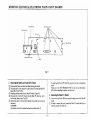
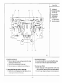
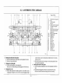
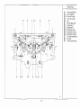
' DISASSEMBLY AND ASSEMBLY OF THE MAIN BODY
12. I Disassembling the Ma.in Body
7.
I.
Re moving the panel
• Remo\'al sequence: lkst, the pattern case whole unir ~s removed, and then
the acce.,ory hox a.'l.•emhly.
1. 1 Removing the puuern ca.<~c whotc unit
Rcmo•·c the two screw•. and then. while lilting the left side of the panel,
• lidc it to the left and remove it rrom the right or the lower •ide plate,
t urning it over and then ursidc down toward the rear or the main body.
• There are liv• connectors joined to the main PC hoard and the control
board on the rear of the rauern ca~ whole unit which make it diffic-ult
to raise the o peration panel. Be sure to exercise sufficient caution when
raising the pau ern ease ~>•hole unir so as n01 to damage cbese
connectors.
1.2 Oisconncct the five conncctnl'!l from t he main PC board and the control
board at the rear ot the pattern case whole unit.
2. Remo•·lnc the oecasory bo• assembly
2. 1 Remove the lWO sc;rews (one or them is inside the at.."OCSS<)ry box), the.n.
while r•isin~t the right side of the IISsembly, slide it toward the right and
~move it !rom the left of the lower side plate.
;1. Remo•inc the -in body
3.1 Removc the three screws from the carrying case reinrorcing place.
.l2 Rcmnve the two '-Crews frorn the. yam tension stand.
.1.3 Remove two"'"'""' c•ch from both the left and right of the needle bed.
3.4 Remove one screw {rom both the ltl\ and right of the front needle bed.
J.5 Remove two main body scre>vs each from both the lcfc and right of the
rear of the main body. and then remove the table clamp SGtting plate.
3.6 Raise the right side oft he needle hed gently and slide it toward the r ight.
'
~2--
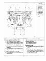
S.
6.
m~ ~.:::;:;,:---L~.----.!l!.....!!lL---r-....,u.t
Take the measurements given the figure ab()vc and write them down.
following the same measuretm:ou again during rcao;scmbly.
Note:
Do not remove the 5 screws on the needle sel«tor plate holder and the 5
screws ()n the needle selector unit unless the n~edle stlector unit i$ being
disa!;S<ru bled .
2. When adjustin& the mounting mcasurcmcn" or the gate peg, the stay
need not he rcmovcd.
3. In chc repair of the main hody mtw-y cam lever and N.S.P. operation
lever.;, the source of the problem may be discovered by rcmuving chc
needle selector solenoid. the rotary cam lever bolder. and the cam lever
spting presser plate.
7.1 Wben the lower holder plate, yarn tension stand and the 16 screws with
wa~hers ()n the tW() gate pes right and center ~tay~ are removed, the
needle selector unit and needle selector plate holder will come off as a
single assembled unit.
1.
rcmovi11g it from the bmt<,m of t he case.
4.
Removinc the netdlc ""leeton unit (with n..,dle sclector plate hulder)
< Cbcclth<· distant< between the needlt ;elector plate holder and the front
needle bed>
Removin&th< left p<,.jtlun sensor PC board ond the richt position"""""' PC
boonl
4.1 Take the screws from each of the PC hoards and remove them.
Removing the cord cover
5.1 Remove the- two screws from the cord cover and remove the cord cover.
RrmoviiiC the belt
6.1 Looocn che pulley adjusting plate screws ( Ref. ~o. C42) on che pulley
holder plate on the left side o f the main body.
6.2 Turn the pulley to move the hch joint before you to the center of the
main hody.
6.3 Remove the belc screws from the hole and remo•-.: the belt .
- 35 -
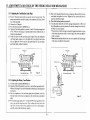
8.
Removin£ the needle selector plate bolder from the needle selector unit
When three needle selector plate holder screws are removed, one froro
the (.'Cuter Slay and two from the right stay, the nt."(.-dlc sc.lector unit
cornes off the needle selector plate holder. The 12 N.S.P. operation
levers in t he ne-edle S<:kctor plate holder and the needle selector unit
also come out.
Removing Ute needle seltctor plate holdrr
9.4 Sliding each nfthe 6 ntedlc sckct<>r plates toward the right, one by nne.
~- I
9.
9.1
9.2
take them off t he 7 grooves on shaft A.
10. Disassembly or the ....,dW, ..lector unit
10.1 Remove the 2 screws from the encoder PC board and re move the
encoder PC board.
10.2 Removing the needle selection solenoid unit.
\Vhcn the two scre\VS are removed. the needle selection solenoid unit
will come off.
Remove lhc center stay, the two operation lever presser screW$. and the
o perstlon lever prc.~ser.
Remove the six needle selector plate springs. (Make sure nf the
mounting direction and position of I he springs before remo ving them.)
I'TI- 124
10.3 Removing the be.-eJ gear Z32
(I) Remove the position sensor hoard holder plate R after removing
the two screws and wac;hers.
(2) Take the snap ring and wa,her from the pulley shaft Rand remove
the bevel gear
NU(e:
The washer on the rear of the bevel gear Z32 has grease on it so be
cautio us that it is not lost when it come~ off.
0
()perac;on lt\'(r Pft:S!('I ~rcu.:-
z.n.
F'ifi:UN ll.l
lJpper,_ .. j
WN
I
YNt
l.ll<atf •···
J
Upper----r-"''N
5
l..u•«·
tippet
4
1.(1-.'(,.
'h~ ''
WIW
~·---..--
·- 6
-·
'.-,_
Hold«
9..}
Remove the needle selector plate 'haft B (angled) snap ring 2.5 from the
rear side of the needle selector plate holder and puU the needle selector
plate shaft o ur toward you.
-36-
10.5 Removing the rotary cam lever
(( ) When the five cam lever spring presser plate screws are taken off.
the cam lever spring presser plate and rotary cam leve1· spring com~
(6) Take out the fou r rotary cam spring pins and pull out four ro tary
cams from rotary cam shaft.
12.2 Assembling the Main Body
off and the 12 rotary cam lever may he taken nut.
1.
Tooooooo-...Cooc.o.:.,._..,,...,. . . . . . --
....
· ········· ---- ·- ~·
r··~-
,;····-··~ ·A~
Card lt'ade: "'id¢
Rl'll~ry('.flr.'l k\~l>prin.~
10.6 Remm'ing the rotary earn
···~----...-
( I) Take out t he lx:vcl gear spring pin and the slit d isc spring pin.
(2) Loosen the right and left rotary cam adjuster collar screws.
(3) Take out t he rotary cam holde r ( left) screws and then the rotary
-.-.- ..
....... ~...-,--
I
R ot&I)' C:lm
cam holder.
(4) When the rotary cam is pulled toward the left and o ut of the rotary
cam holder (right), the hevel gear and spacer will come out.
(5) Take out the slit disc.
lllll'on bVIl)o
1.1 Mounting the rotary cam
( I) Insert t he rotary Cilm into the r otary cam shaft one by o ne. then join
the hollow of the rotary cam to the projection of another rotary ca m
as shown in Figure 12-9.
(2) Place the adjuster collars on10 both e nds ofthe rotary cam assen>bly.
(3) Plaa: the washers onto t he side of the rotary cam assembly with the
bevel gear spring pin hole, pass it 0 1·er the rotary cam holder (right).
plae<: the spacer on, knock the bevel gear spring pin into iL' hole, and
put the bevel gear on.
HotiO'ol,.
f>'ic:wr 12·7
- 37 -
1J Mounting the h<:wl goar 7.,12
(4) Insert the rotary cam hn ldcr (left) onto t he other side of the rotary
~81ll and i"'ort tho •lit di.c and install it to t he main body.
IS) K nock the • lit di•c spring pin into place.
16) Lightly oil the rc~in part of the rntary cam, the metal part o f the
bearin~ 11f the rntary cam holder righ t and left, and the teeth of the
bevel gear with a soap based grease (Epinoch Iii).
1.2 Mounting the mtary cam lever
(I) Apply grease (Epinoch #I) to the card reader guide stopper hole on
1hc rorury cam n1ain body.
t2) lnsc:n the long ~ide of the rotary cam 10\'l:r into t he guide hole of the
main body, and insert the 'hon side into tbe guide bole on the rotary
oowy....,
cam k:\"Cr.
Al ...,• •• • ..................... :..--
"'." f..
..... .
,...
-·"'-
tealkf ~-
( I) Tum the rotary cum until the llat pan of the rotary cam's right end is
hori>ontal, as shown in the figu re ( 12- 11).
(2) Put the washer o n the bevel grar Z32 and place the bevel gear Z32
•uch that its relationship to the rohtry cam i$ as shown in Figure
12· 11.
(3) Put the washer on and <teure it with a <nap ring.
(4) Mount the position sensor hoard hr>ldcr plateR.
Note:
Apply greiiSe (Epinoch # I) tCJthc teeth of both the bevel gear and bevel
"Pfll> .::::::.::: .............-:::. ;·.·;·.:·;.·-
~..
~
!.\ ~
(U! - · ....""'
Rolary( •un ~ ..
le'Yrr
~
<.:am k'vfr
~;;;;;;~;;;;;;;;;;l1:;;;;;;;;l:;:~·'r prtjSUI'I!' pl~ttt
t:ipn 11-11
.
.l ...,...n.,•l
gear Z32.
1,4
(3) Apply 11rease to pal'l< which come in contact with the rotar)' cam
l~ve r and cam ltvcr • pring and install the cam lever spring and t he
cam leve r spring pressure plate. Install the cam lever spring pressure
pl«tc such t hat the side with the bend is to ward the rotary earn lever.
- 38 -
Mountin~ the needle selector unit
( I) Plnc-e lite needle selec tion solen<>id armature on the tip of t he rotary
ct1m le-Yer find install the two inst.a1lation screws.
----------------------------- -------r-------------------------------------.
2.
Mountinc lhr needlr selet:lor plato holder
~..dn:o.
1\.o:dk".wkdl"
"'* 'btl 8
I~
Ot
7""''"
-611-.o
•
0
c
=
--.
>-'rcdlr ~
I
0
••
AAN< .....loo ..
N S P opm!IIIOft Inn
I and the needle selector plate holder >pring hook.
• Tltc rn:allc :.clector plate spring should be hoo ked ~ follows: 3. 2.
ar>d 6, from the needle selector plate holder side. sltould be hooked
to t he s pring book on tbe lo we r side of tht needle selector plate.
"I he remaining plates. '- 5 and 4 s hould he hooked on the spring
hook on the upper side o f the needle sele<:~or plate.
• T he >prings should be hooked alternately tO the top and boll om of
the plates.
(.1) Next place needle selector plate 3 to the needle selector plate holder
in the sequence given in (I) and (2) nbove. Similarly, place the
remaining needle seleclnt• plate<, 5. 2, 4 and (> tn the needle .<elector
plate holder, in that sequenoe (refer to figure 12-13).
(4) After placing the needle selector plates, insert needle selector plate
>haft B (angled) and secure it with a sna p ring 2.5 (refer 10 figure
- So.
~ k \ldrxklll
o:-.~~£: .... -;z./!:.C#i
;-!'L-r-l': ;
.~~-~.:::.=-:---u
~ ':(12·
\
O_tO () 0
coo
(2) !\ext hook the needle selector plate sprin~ ont o needle selech>r pla lc
~--
c
~.1\-.--JL.--~~ " ;;""t"·~.:Jl
••:::.:· -:---~. >·
f)
0
i· ·~·"
..... .. .:. ;;-""' "'~:::1!4
"
~ ,. .........P... ....;. ~·::. -·~•.(~~
!J \;~ •:
,.,..,}< """""
I
(~~7~\~•.
pla.lt'S 1nto lh(lle ~:ro~w~
,.
ri.~
.. ,...,, . .. .·,-;....'2:!16
.........
-11·12
2. 1 The needle selector plate holder should be mounted in the following
st'luente.
(I) Fit noc:dle selector plate number I iato the seven grooves in needle
selector plate ;haft A oft he needle selector plate holder. and. sliding
it toward the left. push it in (refer to ligures 12-12).
• The grooves in needle sckctor plate shaft A go, fro m t ile eteedle
selector plate hoidcr side, in the followi"l! sequence: 1. 3. 5. 2. 4 and
6. Exercic;e suffx::ient caution in th.js rcs•nJ when pushing 1he
needle selector plates into the needle sc:lector plate holder.
• Also be cautious to ensure that the plates 1trc not bent so far that
they break when being in!<Cned.
G :;~W•
t ,'pp<o1
l.o*C'
• ····---:
,,....,. . .,.,
:-4oedJC' !de.::lut
··loW .
::::
12-13).
J. M ounliJillltc Jlftdlo selector unit aad the nudle sdecttw plate holder to the
mOiin body
3.1 Mount the ncedle seloctor pla.t.e holder and ttl( tlecd.le selector unit to the
oent er and riaht slays. Tbe mountirtg holes in the center and right needle
selector plate holder stays and in the needle selector unit arc oblong
horiLontal holes, so use the center of t he hole and t ighten only lightly.
3.2 Put the 12 N.S.P. operation levers through the holes in the needle
selector plate and into the left side of the rolary cam lever and mount the
N.S.P. operation lever presser.
4. MounUng the needk ..eleaoc unit all<l 1m needle selector plote hold..- to the
mllin body
4.1 PlaC<: the needle selector plate shaft B of the needle >elcc1or plate holder
into the angled hole in the main body.
4.2 Put one screw into each oft~~( oblong, vertical holdel"ll in the main bt>dy
fo r the installation oftre center and ril!,ht stays. t ightening it only lightly.
4.J Adjust the center of the bevel gear <!32 so that it has the same
rcl•tio nsbip as in the above figure 12-14 and t i&httn the center and right
>lays.
4.4 Install the table clamp setting plate . and yam take-up stand in such a
way th•• the main body and the needle selecto r p lat o holder will be set in
parallel " i th each o ther.
~ate rf.\====~;:::=i:;::=-
1l ~\
.
s
~
h:':~'" ~·--··~!
; ·
.
6
to~
H-.
- 39 -
;.
0
..
S.
Mo unting the br.h
5.1 T:okc the beh connecting pin such that it is un the inside and p la<-c it ,
liuing onto the hevel gear 7..l2 ~' shtlWn in the fil(ure 12-15.
5.2 Turn the hcvcl gear 7n pulley by t he rib and pull <lut the rear rail side.
5. .1 On t he left side. similarly. placo t he tx:ll "' t hat the long hole in it is
mat-:hed tt) tlu: nvtdt ;n lhl' pulk·y and pull nut to the rear rail sid~ . (in
1wo ~~•I S!:$ out of six}
5.4 t•ull h•>th ends of the bellto~eth~r "' that the connector pins link wit h
the joint hole in lhe Olher.
5.~ ,\dju" 1he pulley :od.it•sting plme. (Rei. No. (.'-41>1 With t h<· pulky pushed
wwarcl tht~
right. adjust lt so that it ::em lll(n1C: 0.~ tu 0.6 rnm and tighten
1he ow:rcw~.
I_
~0 -
12.3 How to adjust the needle bed comb (Rtf. ~o. B-4, 5, 6 In Parts
catalogue)
6. Mo unring lhe tncoder PC: hoard
6.1 Firrhe cncodn PC' board 10 rhe encoder board holder pl•tc. rotary cam
holder Land rigl11en it u p wilh !he twu sc;n:\\">.
6.2 P lao< rhe bo.'<d cord cover and secure il with two S<rew<.
7. Mounrlnc the ltfl position sensor PC board and lhr ri&ht p<>Sition stn<Or PC
board
7. 1 T ighren each o f the PC' ooards do wn wit.h screws.
K. The main body hou$in£
H. l l'lucc I he needle selector plate bolder on the left sid e of I he main body
over· t he left lower side plate a nd put the utnin body under the case.
H.2 Fit und t ighlcn t he ~rcw each on the left And right front portions of
needle bed.
H..l Fit and tighten the two screws each on the left and right needle beds.
8.4 Fit and tighten tile two installation screws on the yarn tension stand.
~. S
Fit and tighten the three screws on the carrying case reinforcing plate.
~.6 Mount the left and right parts of the table cla mp setting plate from the
rear of the main body and tighten each down with two screws.
9. Muwttinc tJw aec....-.ory box assembly
9. 1 l nsort the left part of acces.<nry box into the left lower side pla te.
9.2 Tighten the two (one goes insid e the accessory box) screw(tlte cord for
the left position sensor PC board should pass th rough the rear of t he
cas,e).
10. Mountinc !he pattern ease w'hole unit
10. 1 Insert each of the connectors to the main PC board , rear ofthe pattern
case wh,>le unit (in fiv.: places).
10.2 Insert the right part of pattern case whnlc unit into the lower side plate
right.
10..1 F11 and tighten the two installation sc rews.
I.
Ta ke o ut chc machine body from the lo wer case IISsembly (S<"C p. 35).
Loosen 9 clamping sc rew for needle bed comb on ~tay right, cef'lter·. a nd
lowe r holder plate.
J. Loo<>en 12 damping nuts u n the bac k side of combs with a wren~h.
4. l'ut out thrcx needles each at both ends and in the central part of Ibe
netdle btd and determine a position of combs so as to let needles come to
mid wa)• between both combs. ( Bilateral adj ust ment)
S. Set !in in~ measurement of combs at 143. 1 rnl m at both end s and in Ihe
cent ral pan of the machine body and fa.<~cn with cla mping nuts.
(longitud ial adjustment)
• Note
In Lhis case, keep it in mind that if such nuts are tightened too hard.
r.cre w will be twisted off.
Ad.iu~>l meao;w'ern~ot of fiuing comb~ by usc uf a sliding calipers and
fusten with clamping nuts (reftr 10 Fig . 12- 17).
2.
- 41 -
13. ADJUSTMENT AND CHECK OF THE NEEDLE SELECTOR MECHANISM
13.1 Adjusting the Card Reader Guide Plate
(5) Make a 0.2 mm gap between the rotary cam presser collar and the left ro tar)'
cam holder and tighten the screws. T ighten the four screws each twice to
make sure that they are tight.
(6) Place all the kniuing needles at position B.
(7) Turn the power switch off, turn the K carriage change knob to <KC> and
check all needle, arc selected to position D when the carriage is moved slowly
and when it is moved q uickly.
• The movement of the K carriage is unusually sluggish when there is no gap
( I) Remove the patcern case whole unit and the remove the C(Hd cover. The
paltern case whole unit should be placed, with connectors still joined. to the
rear of the main body.
(2) Connect the AC adapter.
13) Turn the switch on and the MEMO key on.
14) Align all of the knitting needles to position A. set the K cnrriage change knob
to KC. When the K carriage is operated. needle selector solenoids are all
energind to be altr.lcted .
(5) Loosen the screw~ on the card rcadc.r guide stopper. Then. after sliding the
card reader guide stopper over to the right, slide it very lightly back to the
left. and tighten the <crews such that the right window of the card reader
guide plate lightly touches the contact.
in the rolary cam pressure collar or when the gap in the rotary cam ad.juster
collar is too great.
• When there are needles which do not come out to position D. make the gap
in che rohtry c.:am adjustc.r collar greater.
Cartl n:ndtr gtude
('e«l l't".lodtt ! Uidc SICI!)pt'l
'
Strtll.'
fi&-rt Il-l
13.2 Adjusting the Rotary O•m Position
(I) Turn the switch on and the MEMO key on.
(2) Align all of the knitting needles to position A, set the K carriage knob 10 KC.
When the K carriage is operated, needle selector solenoids are all energized to
be anracted.
(.1) After the COHlpletion of the card reader guide plate adjm.tment, lt)osen 1he
four -;cop screws on the rotary t·am adjuster collar and rhe rotary c;tm presser
collar.
(4) Wit h a feeler gauge. make a 0.5 -- O.R mm (TYP 0.7 mm ) gap between the
rolctr}· cam .and th.c rotary L'am lever. Then. h<)ld~ng the rQtary ._;~m) w the
riglu \\·•th a flat ht:ad ~crew Uriv~r . tighten th<.' !'crew (if no fcckr gaugt.~ is
avttilahle. ap('lro'l\imate the distance "bually.)
42-
13.3 Checking the Needle Selector Mechanism
I, The objectins of check sequence I
First of all. in order to determine. whether the cause of the error in needle
selection is in the needle selection mechanism (the mechanism portion). or in
the electronic portions, move the carriage with the power turned off.
When tbe power is turned off, the solenoids are also all off, all of the rotary
cam levers are on the rotary cams, and the knitting needles should all be
selected to position D.
(!)
Am"""'"'"'".'
With this test, the carriage needle selection mechanism. the ruhhing surfaces
of the needle selection solenoid armature. the rotary cam, the rotary c.am
levers, the N.S.P. operation levers. and the needle selector plate may be
checked.
2.
When tbe test determines that not all of the needles come out to position D,
but that some remain in position R.
(I) When there is no regularity (e.g., 6 pitches. I ~ pitches, etc.) in the needles
remaining in position 8
a. The knitting ne~les are bent.
b. The belt has not been properly mounted to the bevel gear Z32
assembly.
c. The rotary cam has not been properly mounted to the rotary encoder.
d. The card reader guide plate or the bevel gear Z32 assembly position
are out of adjustment.
(2) Wh~ tpe needles remai ning the position B show regularity (6 pitches or
6.,.11-fl @il4;lles)
·.
~herll'e~dle selector plat< is not moving because the rotary cam levers
\z·_ and:N.Ii.L",··operauon levers have not been moun~d properly.
b. The rotar.y cam le\'er is gelling caught on thC Ciud reader guide and:
slipping, do not move. Apply grease.
c. The needle sel«tor solenoid armature and the solenoid yoke are
'------------··
3.
c. The N.S.P. operation lever stay is interfering with needle selector
plate number 6.
r. The needle selector plate springs are loose or are interfering with one
another.
When carriage ope ...tion is much heavy
a. The carriage will not move
The carriage will not move when the rotary cam Jever has come loose from
the face of the rotary cam. When too much pressure is applied to the
rotary c.am \ever, it wlll bend. After checking 10 ensure thac lh¢ rotary earn
lever has not l>ecome bent, adjust th~ positions of the card reader guide
plate and the routry cam.
b. Carriage operation is not smooth
The rotary cam pr~sser collar is making contact with the metal ponion of
the left rotary cam holder bearing. The &ap between the rotary cam and
the rotary cam adjuster collar is too wide.
geuing caught, and. sl-ipping, do not move.
d. The armmurc spring of 1he needle selector solenoid is bent or has
come loose.
- 43 -
•