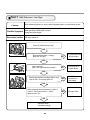
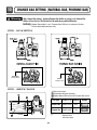
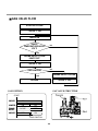
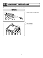
1
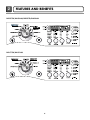
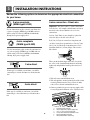
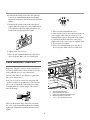
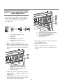
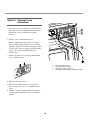
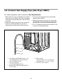
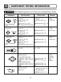
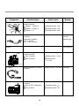
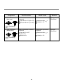
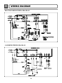
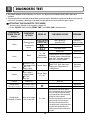
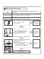
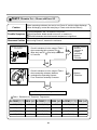
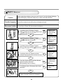
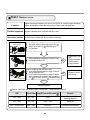
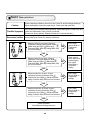
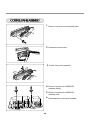
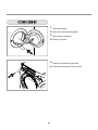
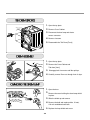
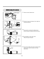
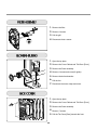
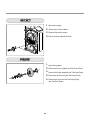
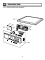
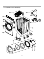
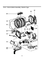
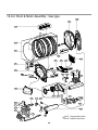
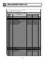
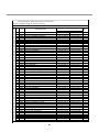
Website:http://www.LGservice.com [For U.S.A]
www.lg.ca [For Canada]
ELECTRIC & GAS DRYER
SERVICE MANUAL
CAUTION
READ THIS MANUAL CAREFULLY TO DIAGNOSE
TROUBLES CORRECTLY BEFORE OFFERING SERVICE.
MODEL : DLE5977W/DLG5988W
DLE5977B/DLG5988B
DLE3777W/DLG3788W
Feb. 2004 PRINTED IN KOREA
P/No.:3828EL3005A
IMPORTANT SAFETY NOTICE
The information in this service guide is intended for use by individuals possessing adequate backgrounds
of electrical, electronic, and mechanical experience. Any attempt to repair a major appliance may result in
personal injury and property damage. The manufacturer or seller cannot be responsible for the
interpretation of this information, nor can it assume any liability in connection with its use.
! WARNING !
To avoid personal injury, disconnect power before servicing this product. If electrical power is required
for diagnosis or test purposes, disconnect the power immediately after performing the necessary checks.
RECONNECT ALL GROUNDING DEVICES
If grounding wires, screws, straps, clips, nuts, or washers used to complete a path to ground are
removed for service, they must be returned to their original position and properly fastened.
WHAT TO DO IF YOU SMELL GAS:
Do not try to light a match, or cigarette, or turn on
any gas or electrical appliance.
Do not touch any electrical switches. Do not use any
phone in your building.
Clear the room, building or area of all occupants.
Immediately call your gas supplier from a neighbor’s
phone. Follow the gas supplier’s instructions
carefully.
If you cannot reach your gas supplier, call the fire
department.
IMPORTANT
Electrostatic Discharge (ESD)
Sensitive Electronics
ESD problems are present everywhere. ESD may damage or weaken the electronic
control assembly. The new control assembly may appear to work well after repair is
finished, but failure may occur at a later date due to ESD stress.
Use an anti-static wrist strap. Connect wrist strap to green ground connection point or unpainted
metal in the appliance.
- OR -
Touch your finger repeatedly to a green ground connection point or unpainted metal
in the appliance.
Before removing the part from its package, touch the anti-static bag to a green ground connection
point or unpainted metal in the appliance.
Avoid touching electronic parts or terminal contacts; handle electronic control assembly by edges only.
When repackaging failed electronic control assembly in anti-static bag, observe above instructions.
2
CONTENTS
1. SPECIFICATIONS ..................................................................................................................4
2. FEATURES AND BENEFITS .................................................................................................... 5
3. INSTALLATION INSTRUCTIONS ........................................................................................... 6
4. DRYER CYCLE PROCESS ..................................................................................................... 12
5. COMPONENT TESTING INFORMATION ..............................................................................13
6. MOTOR DIAGRAM AND SCHEMATIC..................................................................................16
7. CONTROL LAY - OUT .........................................................................................................17
8. WIRING DIAGRAM ............................................................................................................18
9. DIAGNOSTIC TEST .............................................................................................................19
9-1. TEST 1 120VAC ELECTRICAL SUPPLY..........................................................................20
9-2. TEST 2 THERMISTOR TEST --- MEASURE WITH POWER OFF .......................................21
9-3. TEST 3 MOTOR TEST ................................................................................................22
9-4. TEST 4 MOISTURE SENSOR ....................................................................................23
9-5. TEST 5 DOOR SWITCH TEST ...................................................................................24
9-6. TEST 6 HEATER SWITCH TEST - ELECTRIC TYPE...........................................................25
9-7. TEST 7 GAS VALVE TEST - GAS TYPE .........................................................................26
10. CHANGE GAS SETTING (NATURAL GAS, PROPANE GAS) ...............................................27
11. DISASSEMBLY INSTRUCTIONS .........................................................................................29
12. EXPLODED VIEW ..............................................................................................................36
12-1. CONTROL PANEL & PLATE ASSEMBLY .......................................................................36
12-2. CABINET & DOOR ASSEMBLY...................................................................................37
12-3-1. DRUM & MOTOR ASSEMBLY : ELECTRIC TYPE ........................................................38
12-3-2. DRUM & MOTOR ASSEMBLY : GAS TYPE ...............................................................39
13. REPLACEMENT PARTS LIST
3
1
SPECIFICATIONS
ITEM
Color
Material &
Finishes
DLE5977W
DLG5988W
DLE5977B
DLG5988B
Blue White
Black
DLE3777W
DLG3788W
Blue White
Top Plate
Porcelain
Painted
Door Trim
Chromate + STS Deco
Blue White
POWER SUPPLY
ELECTRICITY
CONSUMPTION
REMARK
120V / 240V 60Hz (26A)
MOTOR
250W (4.5A)
AC 120V
HEATER
5400W (22.5A)
AC 240V ( ELECTRIC TYPE)
LAMP
15W (125mA)
AC 120V
GAS VALVE
AC 120V ( GAS TYPE)
13W (110mA) X 2
CONTROL TYPE
Electronic
DRUM CAPACITY
7.3 cu.ft.
126 / 144
Weight (lbs): Net / Gross
No. of Programs
9
7
No. of Dry Option
5
5
No. of Temperature Controls
5
5
No. of Dry Levels
5
5
Audible End of Cycle Beeper
High / Low / Off
Moisture
Equipped
Electro sensor
Temperature
Equipped
Thermistor
Sensor
Reversible Door
Adopted
Drum
Stainless Steel
Dryer Rack
Equipped
Child Lock
Equipped
Interior Light
Equipped
Product (WXHXD)
27" x 42 3/4" x 28 1/3"
Packing (WXHXD)
29 1/2" x 44 3/4" x 30 3/4"
4
2
FEATURES AND BENEFITS
DLE5977W/DLG5988W/DLE5977B/DLG5988B
DLE3777W/DLG3788W
5
3
INSTALLATION INSTRUCTIONS
Review the following options to determine the appropriate electrical connection
for your home:
3-wire receptacle
(NEMA type10-30R)
4-wire connection : Direct wire
Important : The places where a 4-wire connection
is needed are , for example, mobile homes and areas
that local codes do not admit the use of 3-wire
connections.
Use the instructions at this section if your home has
a 3-wire receptacle (NEMA type 10-30R) and you
will be using a UL listed, 120/240 volt minimum,
30 amp, dryer power supply cord.
At least, 5ft(1.52m) of extra length is required in
order for dryer to be able to be moved.
Peel 5 in (12.7cm) of external covering from end
4-wire receptacle
(NEMA type14-30R)
31/2"
(8.6 cm)
5"
(12.7 cm)
of cable, leaving bare ground wire at 5 in (12.7cm).
Cut 11/2 in. (3.8cm) from 3 remaining wires. Peel
insulation back 1in. (2.5cm). Shape ends of wires
like a hook.
1" m)
Use the instructions at this section if your home has
a 4-wire receptacle (NEMA type 14-30R) and you
will be using a UL listed, 120/240 volt minimum,
30 amp, dryer power supply cord.
5c
(2.
5
(12.7 "
cm)
Then, put the hooked shape end of the wire under
the screw of the terminal block(hooked end facing
rightward) and pinch the hook together and screw
tightly.
3 wire direct
31/2"
(8.6 cm)
5"
(12.7 cm)
(
If this type is available at your home. you will be
connecting
to a fused disconnect or circuit
breaker
1" m)
1" )
c
m
c
box
5
.
5
(2
(2.
1.Take off center terminal block screw
2.Take off appliance neutral ground wire(white) from
external ground connector screw. Fasten it under
center, silver colored terminal block screw.
3.Connect ground wire(green) of power supply cable
to external ground conductor screw. Tighten screw.
3V2"
)
(8.9 cm
5
(12.7 "
cm)
4 wire direct
31/2"
(8.6 cm)
5"
(12.7 cm)
If this type is available at your home. you will be
connecting to a fused disconnect
or circuit breaker
1" m)
c
box
5
(2.
5
(12.7 "
cm)
1" )
cm
2
( .5
3V2"
)
(8.9 cm
6
d
e
f
c
a
b
a.
b.
c.
d.
e.
f.
External ground connector
Green copper wire of power supply cord
3/4 in. (1.9cm) UL-listed strain relief
Center silver-colored terminal block screw
Neutral grounding wire(white)
Neutral wire(white or center wire)
4. Put the hooked shape ends of the wire under the
screw of the terminal block(hooked end facing
rightward) and squeeze the hook together and screw
tightly.
5. Put the hooked shaped ends of the other power
supply cable wires under the outer terminal block
screws(hooked end facing right) and squeeze the
hooked ends together and screw tightly.
1. Take off center terminal block screw
2. Put the hooked end of the neutral wire(white) of
power supply cable under the center screw of
terminal block). Squeeze the hooked end together
3. Connect the hooked ends of the other power
supply cable to the center screw of terminal block.
4. Screw strain relief tightly.
5. Place tab of terminal block cover into slot of
dryer rear panel. Make sure cover with screw.
6. Tighten strain relief screws.
7. Place the tab of terminal block cover into slot of
dryer rear panel. Make sure cover with screw.
3-wire connection : Direct wire
c
Important : The places wherea 4-wire connection is
needed are mobile homes and areas that local codes
do not admit the use of 3-wire connections.
b
d
a
At least, 5ft(1.52m) of extra length is required for
dryer to be able to move.
e
Peel 5 in (12.7cm) of external covering from end
of cable,
3 " leaving bare ground wire at 5 in (12.7cm).
(8.6 cm)
1
Cut 1 /2 in. (3.8cm) from 3 remaining wires. Strip
insulation back 1in. (2.5cm). Shape ends of wires
into a hook shape.
1/
2
m)
1" m)
c
5
(2.
5
(12.7 "
cm)
1"
(2.5
a.
b.
c.
d.
e.
)
cm
3V2"
)
(8.9 cm
Then, put the hooked shape end of the wire under
the screw of the terminal block(hooked end facing
rightward) and pinch the hook together and screw
tightly.
7
External ground connector
Neutral grounding wire (white)
Center silver-colored terminal block screw
Neutral wire (white or center wire)
3/4 in. (1.9 cm) UL-listed strain relief
Option 1: 3-Wire Connection with
a Power Supply Cord
lf your local codes or ordinances permit the
connection of a frame-grounding conductor to the
neutral wire, use these instructions. If your local
codes or ordinances do not allow the connection of
a frame-grounding conductor to the neutral wire,
use the instructions under Section 3: Optional
3-wire connection.
c
b
d
a
a
d
g
a.
b.
c.
d.
e.
f.
g.
e
f
a.
b.
c.
d.
e.
3-wire receptacle (NEMA type 10-30R)
3-wire plug
Neutral prong
Spade terminals with up turned ends
3/4 in. (1.9 cm) UL approved strain relief
Ring terminals
Neutral (white or center wire)
External ground connector
Neutral grounding wire (white)
Center silver-colored terminal block screw
Neutral wire (white or center wire)
3/4 in. (1.9 cm) UL-listed strain relief
3. Connect the other wires to outer terminal block
screws. Tighten screws.
1. Loosen or remove center terminal block screw.
4. Tighten strain relief screws.
2. Connect neutral wire (white or center wire) of
power supply cord to the center, silver colored
terminal screw of the terminal block. Tighten
screw.
5. Insert tab of terminal block cover into slot of
dryer rear panel. Secure cover with hold-down
screw.
8
Option 2: 4-wire connection with a
Power supply cord.
d
e
f
c
• lf your local codes or ordinances do not allow the
use of a 3 wire connection, or you are installing
your dryer in a mobile home, you must use a 4wire connection.
a
b
a.
b.
c.
d.
e.
f.
g.
a.
b.
c.
d.
e.
f.
4-wire receptable (NEMA type 14-30R)
4-pront plug
Ground prong
Neutral Prong
Spade terminals with upturned ends
3/4 in. (1.9 cm) UL approved strain relief
Ring terminals
5. Connect the other wires to outer terminal block
screws. Tighten screws.
1. Remove center terminal block screw.
2. Remove appliance neutral ground wire (white)
from external ground connector screw. Fasten it
under the center, silver colored terminal block
screw.
6. Tighten strain relief screws.
7. Insert tab of terminal block cover into slot of
dryer rear panel. Secure cover with hold-down
screw.
b
c
a
a.
b.
c.
External ground connector - Dotted line
shows position of NEUTRAL ground wire
before being moved to center terminal block
screw
Center silver-colored terminal block screw
White wire of harness
3. Connect ground wire (green or bare) of power
supply cable to external ground conductor screw.
Tighten screw.
4. Connect neutral wire (white or center wire) of
power supply cord to the center, silver colored
terminal screw of the terminal block.
External ground connector
Green or bare copper wire of power supply cord
3/4 in. (1.9 cm) UL-listed strain relief
Center silver-colored terminal block screw
Neutral grounding wire (white)
Neutral wire (white)
9
Option 3: Optional 3-wire
connection.
• If your local codes or ordinances do not allow the
connection of a frame-grounding conductor to the
neutral wire, use the instructions under this
section.
b
c
a
1. Remove center terminal block screw.
2. Remove appliance neutral ground wire (white)
from external ground connector screw. Connect
appliance ground wire and the neutral wire (white
or center wire) of power supply cord/cable under
center, silver colored terminal block screw.
Tighten screw.
d
3. Connect the other wires to outer terminal block
screws. Tighten screws.
a.
b.
c.
d.
4. Tighten strain relief screws.
5. Insert tab of terminal block cover into slot of
dryer rear panel. Secure cover with hold-down
screw.
6. Connect a separate copper ground wire from the
external ground connector screw to an adequate
ground.
10
External ground connector
Neutral grounding wire (white)
Neutral wire (white or center wire)
Grounding path determined by a qualified electrician
3-2. Connect Gas Supply Pipe (Gas Dryer ONLY)
For further assistance, refer to section on Gas Requirements.
1. Make certain your dryer is equipped for use with the
type of gas in your laundry room. Dryer is equipped
at the factory for Natural Gas with a 3/8” N.P.T. gas
connection.
2. Remove the shipping cap from the gas connection
at the rear of the dryer. Make sure you do not
damage the pipe thread when removing the cap.
3. Connect to gas supply pipe using a new flexible
stainless steel connector.
4. Tighten all connections securely. Turn on gas and
check all pipe connections (internal & external) for
gas leaks with a non-corrosive leak detection fluid.
5. For L.P. (Liquefied Petroleum) gas connection, refer
to section on Gas Requirements.
1
2
5
3
4
1 New Stainless Steel Flexible Connector - Use
only if allowed by local codes (Use Design
A.G.A. Certified Connector)
2 1/8” N.P.T. Pipe Plug
(for checking inlet gas pressure)
3 Equipment Shut-Off Valve-Installed within 6’
(1.8 m) of dryer
4 Black Iron Pipe
Shorter than 20’ (6.1 m) - Use 3/8” pipe
Longer than 20’ (6.1 m) - Use 1/2” pipe
5 3/8” N.P.T. Gas Connection
11
4
DRYER CYCLE PROCESS
Default
Cycle
Sensor
Dry *
Conditions of operation and termination
Drying
Cooling
Temp- Dry Display
erature Level time Electro- Temp- Default Tempsensor Control time Control**
HEAVY DUTY
HIGH (Normal) 54min Saturation 68±4°C (5min) 47±5°C
COTTON/
TOWELS
MID
(Normal) 55min Saturation 66±4°C (5min) 47±5°C
HIGH
NORMAL
MEDIUM (Normal) 41min Saturation 60±4°C (5min) 47±5°C
Wrinkle care
Time
3Hr
PERM
PRESS
LOW
(Normal) 36min Saturation 52±3°C (5min) 47±5°C
DELICATES
LOW
(Normal) 32min Saturation 52±3°C (5min) 38±5°C
ULTRA
DELICATE
SPEED DRY
Manual
FRESHEN UP
Dry **
AIR DRY
ULTRA
(Normal) 34min Saturation 45±3°C (5min) 38±5°C
LOW
(HIGH)
-
25min Saturation (70±5°C) (5min) (47±5°C)
(MID
HIGH)
-
20min
Saturation (66±5°C) (5min) (47±5°C)
-
-
30min
Saturation
No
heater
N/A
3Hr
N/A
Off Time: 6min
Motor
On Time: 10sec
Load
Temperature Control for each cycle
Heater
* Sensor dry : “Dry Level” is set by users.
** Manual dry : “Temperature control” is set by users.
Default settings can be adjusted by users.
12
5
!
COMPONENT TESTING INFORMATION
CAUTION When checking the Component, be sure to turn the power off, and do voltage discharge sufficiently.
Component
1. Thermal cut off
• Check Top Marking :
N130
2. Hi limit Thermostat
(Auto reset)
3. Outlet Thermostat
( Auto reset)
• Check Top Marking :
N85
Test Procedure
Remark
• Heater caseMeasure resistance of terminal If thermal fuse is open must
Safety
to terminal
be replaced
±
•
Electric
type
Open at 266 12°F
Resistance value
∞
±
(130 7°C)
Auto reset -31°F (-35°C)
Continuity (250°F ) < 1Ω
Same shape as Outlet Thermostat.
Measure resistance of terminal
to terminal
Open at 257 ± 9°F
(125 ± 5°C)
Close at 221 ± 9°F
(105 ± 5°C)
Measure resistance of terminal
to terminal
Open at 185 ± 9°F
(85 ± 5°C)
Close at 149 ± 9°F
(65 ± 5°C)
Same shape as Thermal cut off.
4. Lamp holder
Measure resistance of terminal
to terminal
5. Door switch
Measure resistance of the
following terminal
1) Door switch knob : open
Terminal : “COM” - “NC” (1-3)
Terminal : “COM” - “NO” (1-2)
2) Door switch push : push
Terminal : “COM” - “NC” (1-3)
Terminal : “COM” - “NO” (1-2)
6. Idler switch
Check result
Measure resistance of the
following terminal :
“COM - NC”
13
Resistance value
∞
• Heater case Hi limit
• Electric type
Resistance value < 5Ω
Resistance value
∞
• Blow housing Safety
• Electric type
Resistance value < 5Ω
Resistance value :
80Ω ~ 100Ω
Resistance value < 1Ω
Resistance value
∞
Resistance value
∞
Resistance value < 1Ω
1. lever open
Resistance value < 1Ω
2. Lever push (close)
Resistance value
∞
The state that
Knob is
pressed is
opposite to
Open
condition.
Component
7. Heater
Test Procedure
Measure resistance of the
following terminal
Terminal : 1 (COM) - 2
Terminal : 1 (COM) - 3
Terminal : 2 - 3
8. Thermistor
Measure resistance of terminal
to terminal
Temperature condition :
58°F ~ (10~40°C)
58°F ~ 104F (10~40°C)
Check result
• Electric type
Resistance value : 10Ω
Resistance value : 10Ω
Resistance value : 20Ω
Resistance value : 10Ω
9. Motor
10. Gas valve
Remark
• Heater case Hi limit
• Electric type
• See Page 13
valve 1
Measure resistance of the
following terminal
Valve 1 terminal
Valve 2 terminal
• Gas type
Resistance value : > 1.5kg ~
Resistance value :
> 1.5~2.5kg
valve 2
11. Igniter
Measure resistance of terminal
to terminal
Resistance value : 100~800Ω • Gas type
12. Frame Detect
Measure resistance of terminal
to terminal
Open at 370°F ((Maximum)
Close at 320°F
• Gas type
14
Resistance value
∞
Resistance value < 1Ω
Component
13. Outlet Thermostat
(Auto reset)
Test Procedure
Measure resistance of terminal
to terminal
Open at 203 ± 7°F (95 ± 5°C)
Close at 158 ± 9°F (70 ± 5°C)
Check result
Remark
• Gas type
• Gas funnel
Resistance value
Continuity < 1Ω
∞
• Check Top Marking :
N95
13. Outlet Thermostat
(Manual reset)
Measure resistance of terminal
to terminal
Open at 212 ± 12°F
(100 ± 7°C)
Manual reset
• Check Top Marking :
N100
15
If thermal fuse is open must
be replaced
Resistance value
∞
Continuity < 1Ω
• Gas type
• Gas funnel
6
MOTOR DIAGRAM AND SCHEMATIC
NOTE When checking Component, be sure to turn Power off, then do voltage discharge sufficiently.
Contact On / Off by Centrifugal Switch
STOP MODE
(When Motor does not operate)
RUN MODE
(Motor operates)
Centrifugal switch
(Pull Drive forward)
Centrifugal switch
16
7
CONTROL LAY - OUT
PWB ASSEMBLY DISPLAY LAY-OUT
MODEL DISPLAY AS DIAGNOSTIC TEST
OPTION PART
OP 1
OP 2
OP 3
OP 4
OP 5
OP 6
LED
DISPLAY
DLE5977W/B
X
X
X
O
X
X
18:FO
6871EC1115A
DLG5988W/B
X
X
O
O
X
X
19:FO
6871EC1115B
DLE3777W
X
X
X
X
X
X
18:F1
6871EC1115C
DLG3788W
X
X
O
X
X
X
19:F1
6871EC1115D
MODEL
PWB ASSEMBLY LAY-OUT
17
P/No
8
WIRING DIAGRAM
ELECTRIC DRYER WIRING DIAGRAM
GAS DRYER WIRING DIAGRAM
18
9
DIAGNOSTIC TEST
1. This TEST should be used for Factory test /Service test. Do not use this DIAGNOSTIC TEST other than
specified.
2. Activating the Heater manually with the Door open may trip the Thermostat attached to the Heater, therefore do
not activate it manually. (Do not press the door switch to operate the heater while the door is open )
ACTIVATING THE DIAGNOSTIC TEST MODE
1. Unit must be in Standby (unit plugged in, display off)
2. Press “POWER” while pressing “MORE TIME”, and “LESS TIME” simultaneously.
Pressing the
“START/PAUSE”
button
None
CHECKING
ACTION
DISPLAY
Electric control
&
Temperature
sensor
CHECKING POINT
REMARK
Won’t power up
Defective LED
See test 1
Display : See page
Thermistor open
See test 2
Thermistor close
Motor runs
Once
Twice
3 times
4 times
Motor
ELECTRIC TYPE
Motor + Heater 1 (2700W)
GAS TYPE
Motor + Valve
ELECTRIC TYPE
Motor + Heater 1
+Heater 2 (5400W)
GAS TYPE
Motor Type
70 ~ 239
Displays Moisture Sensor Operation:
Measured
If moisture sensor is contacted with
Moisture Value. damp cloth. The display number is
below 180, in normal condition.
Current Temp.
See test 4
Gas valve
See test 7
Current Temp.
(5 ~ 70)
Auto Off
Control Off
Door switch
Motor & Heater Off + Lamp On +
During check,
Buzzer beeps seven times
If the door is open.
Motor on & Heater
During check,
Off + Lamp Off
If the door is closed.
ELECTRIC TYPE : Heater runs
GAS TYPE : GAS Valve runs
(Display the Temperature of
Inside drum.)
See test 3
70 ~ 239
19
Lamp
• Press Start button 1 time and then open the
door. Proceed again with the step 1(by pressing
start 1 time), step 2(by pressing start 2 times),
step 3(by pressing start 3 times) and step 4(by
pressing start 4 times) in sequence.
• Press Start 2 times and then open the door. Proceed
again from the step 1 all the way to the step 4.
• Press Start 3 times and then open the door
Proceed with the step 1 and skip the step 2 and
press step 3 twice and finish with step 4 by
making sure the all the electric devices shut off
in the end.
See test 6
Test 1 120VAC Electrical supply
When measuring power, be sure to wear insulated gloves, to and avoid an
electric shock.
Caution
Trouble Symptom No power was applied to Controller. (LED, Display off)
Measurement Condition With Dryer Power On; Connector linked to Controller.
Check the outlet, is the voltage
110V ~ 125V AC?
NO
• Check the fuse
or circuit breaker.
NO
• Check if Power
Cord is properly
connected.
NO
• Reconnect the
controller.
YES
Check if the voltage measured between
Connector “RD3- ” (Black) linked to the
Controller and “WH3- ”(White) is
110V ~ 125V?
YES
N(White)
L (Black)
L (Led)
Check if the Controller wire is
disconnected.
Check if Terminal Block and Power Cord
are connected (Check Plug ).
- Does Power Cord N( Natural) line match
to Terminal Center N(Natural) line?
YES
Replace controIler.
20
Test 2 Thermistor Test --- Measure with Power Off
Caution
Trouble Symptom
Before measuring resistance, be sure to turn Power off, and do voltage discharge.
(When discharging, contact the metal plug of Power cord with the Ground.)
During Diagnostic Test, tE1 and tE2 Error occur.
During operation, Heater would not turn off, or remains on.
Difference between actual and sensed temperature is significant.
Measurement Condition After turning Power off, measure the resistance.
Take 6pin Connector from
the Controller.
Check if resistance is in the range of Table 1
when measuring 6pin connector Pin
YES
(Blue wire) and Pin
(Red wire) connected
to Controller.
• Check if Control
and 6Pin
connector is
properly
connected.
• Replace
Controller.
NO
Check if resistance is in the range of Table 1
when measuring resistance between
terminals after separating Harness
From Thermistor assembly Connector.
NO
• Replace
Thermistor.
YES
Check Harness-linking connector.
Table 1. Resistance for Thermistor Temperature.
Air TEMP.[°F (°C)] RES. [kΩ] Air TEMP.[°F (°C)] RES. [kΩ] Air TEMP.[°F (°C)] RES. [kΩ]
50°F (10°C)
18.0
90°F (32°C)
7.7
130°F (54°C)
2.9
60°F (16°C)
14.2
100°F (38°C)
6.2
140°F (60°C)
3.0
70°F (21°C)
11.7
110°F (43°C)
5.2
150°F (66°C)
2.5
80°F (27°C)
9.3
120°F (49°C)
4.3
160°F (71°C)
2.2
21
Test 3 Motor test
Caution
Before measuring resistance, be sure to turn Power off, and do voltage discharge.
(When discharging, contact the metal plug of Power cord with earth line.)
Trouble Symptom Drum will not rotate; No fan will function; No Heater will work.
Measurement Condition Turn the Dryer’s Power Off, then measure resistance.
Is resistance below 3Ω between Connector
“WH3- ” (White wire) and “BL2- ” (Brown wire)? YES
Measure while door is closed.
NO
Is resistance below 3Ω between Connector
“WH3- ” (White wire) and “BL2- ” (Yellow wire)? NO
Measure while door is closed.
YES
Is resistance below 3Ω between Connector
“BL2- ” (Yellow wire) and “BL2- ” (Brown wire)? YES
NO
Is resistance below 1Ω between terminals
NO
of Outlet Thermostat attached to blower housing?
• Replace Control.
(Relay check)
• Check Controller
connector.
• Check if Door flame
presses door switch
knob.
• Check Door Switch.
• Check Harness
connection.
• Replace Control.
(Relay check)
• Check Controller
connector.
• Replace Outlet
• Thermostat.
(Refer to
‘Component’)
YES
Idler Switch Lever Idler Switch
Does Idle Switch attached to Motor Bracket
operate Level by drum belt?
(Not operating Lever is normal.)
YES
Is resistance below 1Ω between Idler Switch
terminals?
NO
YES
• Check Motor.(Refer to ‘Motor Diagram & Check’)
• Check if Control Connector is contacted.
22
• Check Idler Assembly.
• Drum Belt cuts off
• Drum Belt takes off
from
• Motor Pulley.
• Replace Idler
Switch.
Test 4 Moisture sensor
Before measuring resistance, be sure to turn Power off, and do voltage discharge.
(When discharging, contact the metal plug of Power cord with earth line.)
Caution
Trouble Symptom Degree of dryness does not match with Dry Level.
Measurement Condition Turn the Dryer’s Power Off, then measure resistance.
Take 6pin Connector from
the Controller.
Short with metal to 6pin connector’s Pin
(BLUE wire) and Pin
(ORANGE wire)
to Controller.
Metal or Wire
When measuring resistance in Electric load,
is resistance below 1Ω?
NO
YES
Damping cloth
When contacting cloth to Electro load:
1. Is the measurement within the range of Table 2
during Diagnostic Test?
NO
2. Is the measurement within the range of Table 2
when measuring the voltage in 6pin connector’s
Pin (BLUE wire) and Pin (ORANGE wire)?
• Check Electro Load
and
• Harness Connector.
• Check Harnesslinking connector.
• Replace Control
and Check.
YES
Normal Condition
Table 2. IMC Ratio and Display Value / Voltage (IMC : Initial Moisture Content)
IMC
Display Value Voltage(DC) (between 6Pin terminal
)
Remark
70% ~ 40%
50 ~ 130
2.5V
Weight after removing from
Washing Machine
40% ~ 20%
100 ~ 20
2.0V ~ 4.0V
Damp Dry
10% ~ Dried clothes
205 ~ 240
Over 4.0V
Completely-dried clothes
23
Test 5 Door switch test
Caution
Before measuring resistance, be sure to turn Power off, and do voltage discharge.
(When discharging, contact the metal plug of Power cord with earth line.)
Door Opening is not sensed.(During operation, when opening Door, Drum motor and
Trouble Symptom Heater run continuously; Door Close is not sensed.
(Drum motor will not operate. Display will flash at 0.5 second intervals.)
Measurement Condition After turning Dryer Power Off, measure resistance.
Measure while Door is closed. Check if
resistance is below 250Ω between “WH3- ”
(White wire) and “RD3- ”(Black wire)
Connector WH3, RD3 after taking WH3, RD3
out from Controller.
YES
• Door switch
Check (Refer to
Component
testing.)
NO
• Check Lamp.
(When opening
Lamp, replace then
measure again.)
• Door switch
Check(Refer to
Component
testing.)
NO
Measure while Door is open. Check if
resistance is 300~60Ω between “WH3- ”
(White wire) and “RD3- ” (Black wire)
Connector WH3, RD3 after taking WH3, RD3
out from Controller.
YES
Measure while Door is open. Check if
resistance is below 1Ω between “BL2- ”
YES
(Yellow wire) and “WH3- ” (White wire) after
taking Connector WH3, BL2 out from Controller.
• Door switch
Check (Refer to
Component
testing.)
NO
Measure while Door is closed. Check if
resistance is below 1Ω between “BL2- ”
NO
(Yellow wire) and “WH3- ” (White wire) after
taking Connector WH3, BL2 out from Controller.
YES
Check Controller.
Check Harness-linking connector.
24
• Door switch
Check (Refer to
Component
testing.)
Test 6 Heater switch test - Electric Type
Before measuring resistance, be sure to turn Power off, and do voltage discharge.
(When discharging, contact the metal plug of Power cord with earth line.)
Caution
While operating, Heating will not work.
Trouble Symptom Drying time takes longer.
Measurement Condition After turning Power off, measure the resistance.
1. Is resistance between Heater terminal
and
below 18 ~ 22Ω?
2. Is resistance between Heater terminal
and
below 18 ~ 22Ω?
3. Is resistance between Heater terminal
and
below 9 ~ 11Ω?
NO
• Replace Heater.
YES
Check if the value of measured resistance is
below 1Ω between terminal TH2 (Safety Thermostat). NO
TH3
TH2
• Replace TH2
(Safety Thermostat).
YES
Check if the value of measured resistance is below
NO
1Ω between terminal TH3 (HI-Limit Thermostat).
• Replace TH3
(HI-Limit Thermostat).
YES
Check Motor. Check if the value of measured
resistance is below 1Ω between terminal
and
at RUN condition.
YES
Check Controller.
Check Harness-linking Connector.
25
NO
• Check Motor and
replace it.
Test 7 GAS Valve test - Gas Type
Caution
When measuring power, be sure to wear insulated gloves, to avoid electric shock.
While operating, Heating will not work.
Trouble Symptom Drying time takes longer.
Measurement Condition With dryer power on
Power On & Start (Normal Cycle)
NO
Valve 1
When measuring Valve 1 voltage,
More than AC 90V?
NO
• Check thermostat
Hi limit Safety
NO
• Check Igniter &
Frame detect
YES
• Check Gas
connection or
Gas supply
YES
• Change Valve
YES
Igniter operates?
(after 1 min, Igniter becomes reddish)
Igniter
YES
Valve 2
When measuring Valve 2 voltage, Value is more
than AC 90V? (10 sec after Igniter off)
NO
When measuring terminal resistance on “Valve 1”,
“Valve 2”, Value is more than1.5 ~ 2.5kΩ?
(Measure after Off )
NO
• Harness check
• Controller change
26
10
!
CHANGE GAS SETTING (NATURAL GAS, PROPANE GAS)
Warning
After Natural Gas Setting, applying Propane Gas Orifice or wrong use of Natural Gas
Orifice will result in fire. Conversion must be made by a qualified technician.
Initially, Natural Gas mode is
set. Propane Gas Orifice is on sale as a Service
Part to authorized servicers only.
STEP 1 : VALVE SETTING
Full open
“Change screw”
Close
“Change screw”
STEP 2 : ORIFICE CHANGE
Remove 2 screws.
Disassemble the pipe assembly.
Replace Natural Gas orifice with Propane Gas orifice.
Gas type
Orifice P/No Marking
Natural Gas 4948EL4001B
NCU
Propane Gas 4948EL4002B
PCU
Shape
Kit contents : Orifice (Dia. = 1.613mm, for Propane Gas)
: Replace Label
: Instruction sheet
Orifice
27
GAS VALVE FLOW
START KEY PUSH
“VALVE 1” ON
IGNITE ON
IGNITE
TEMPERATURE ABOUT
370”F
NO
YES
FRAME DETECT OPEN
IGNITE OFF
“VALVE 2” ON
GAS IGNITION
NO
FRAME DETECT CLOSE
YES
DRYING
“VALVE 2” OFF
GAS IGNITION
GAS VALVE STRUCTURE
START
VALVE 1
ON
IGNITER
ON
OFF
FRAME
DETECT
CLOSE
OPEN
OFF
ON
VALVE 2
GAS IGNITION
28
11
DISASSEMBLY INSTRUCTIONS
Disassemble and repair the unit only after pulling out power plug from the outlet.
1. Remove 3 screws on the plate upper.
2. Push the top plate
3. Open the top plate
29
1. Remove 2 screw on the control panel frame.
2. Disconnect the connectors.
3. Pull the control panel assembly.
4. Remove 9 screws on the PWB(PCB)
assembly, display.
5. Remove 4 screws on the PWB(PCB)
assembly, main.
6. Disassemble the control panel assembly.
30
1. Open the top plate.
2. Open the control panel assembly.
3. Open the door assembly.
4. Remove 2 screws.
5. Remove 4 screws from upper side.
6. Disconnect the harness of door switch.
31
1. Open the top plate.
2. Remove Cover Cabinet.
3. Disconnect the door lamp and electro
sensor connector.
4. Remove 4 screws.
5. Disassemble the Tub Drum [Front].
1. Open the top plate.
-1
-1
2. Remove the Cover Cabinet and
Tub drum [front].
-2
3. Disengage belt from motor and idler pulleys.
4. Carefully remove Drum out through front of dryer.
1. Open the door.
2. Remove the screw holding the drum lamp shield
in place.
3. Slide the shield up and remove.
4. Remove the bulb and replace with a 15 watt,
120 volt candelabra-base bulb.
5. Replace the lamp shield and screw.
32
1. Remove screw & exhaust duct.
2. Detach and remove the bottom, left or right side
PORTION “A”
knockout as desired.
3. Reconnect the new duct[11 in(28cm)] to the
DUCT
TAPE
blower housing, and attach the duct to the base.
4. Pre-assemble 4" elbow with 4" duct.
Wrap duct tape around joint.
DUCT
TAPE
5. Insert duct assembly, elbow first, through the side
DUCT
TAPE
opening and connect the elbow to the dryer
internal duct.
33
1. Remove the filter.
2. Remove 3 screws.
3. Pull the grill.
4. Disconnect electro sensor.
1. Open the top plate.
2. Remove the Cover Cabinet and Tub Drum [Front].
3. Remove the Drum assembly.
4. Remove 2 screws and cover(Air guide).
5. Remove the bolt and washer.
6. Pull the fan.
7. Disconnect the motor clamp and motor.
1. Open the top plate.
2. Remove the Cover Cabinet and Tub Drum [Front].
3. Remove the Drum assembly.
4. Remove 7 screws.
5. Pull the Tub Drum [Rear] towards the front.
34
1. Open the top plate.
2. Remove the Cover Cabinet.
3. Remove filter and 2 screws.
4. Pull the air duct towards the front.
1. Open the top plate.
2. Remove the Cover Cabinet and Tub Drum [Front].
3. Remove the Drum assembly and Tub Drum [Rear].
4. Disconnect Air duct from the Tub Drum [Front].
5. Remove the roller from the Tub Drum [Front]
and Tub Drum [Rear].
35
12
EXPLODED VIEW
12-1. Control Panel & Plate Assembly
A210
A130
A120
A110
36
12-2. Cabinet & Door Assembly
A700
A800
A390
A330
A600
A500
A320
A310
A400
A410
37
A460
12-3-1. Drum & Motor Assembly : Electric Type
F200
K400
K120
K140
K100
K130
K250
K310
K330
K320
K340
K221
K210
K250
K550
K560
K610
K240
F140
K510
K520
K640
F130
K650
F110
38
12-3-2. Drum & Motor Assembly : Gas type
F200
K400
K120
K140
K100
K130
K250
K310
K330
K320
K340
K221
K210
K250
K550
K560
K610
K240
K510
M150
M240
K520
K640
M220
M160
K650
M171
M170
M210
M140
M230
M110
M190
M171 : Propane Gas orifice
M170 : Natural Gas orifice
M180
M181
39
REPLACEMENT PARTS LIST
13
CAUTION : Before replacing any part of these components,
read carefully the safety precautions in this manual.
¡Æ Note : S(Safety Parts), AL(Alternative parts)
L G M O D E L : T D - V 10050E, TD- V 10051E
S
AL
LOC
DESCRIPTION
A500
K610
K650
MODEL P/N
QTY
DLE5977W
DLE3777W
CABINET ASSEMBLY
MOTOR ASSEMBLY,WM
PULLEY ASSEMBLY,MOTOR
3091EL0003A
4681EL1002A
4561EL3002A
3091EL0003A
4681EL1002A
4561EL3002A
1
1
1
K640
K510
K520
SWITCH,MICRO
BLOWER ASSEMBLY
HOUSING ASSEMBLY (MECH),BLOWER
3W40025D
5835EL1002A
3661EL1001C
3W40025D
5835EL1002A
3661EL1001C
1
1
1
K550
K560
THERMISTOR ASSEMBLY
THERMOSTAT ASSEMBLY
6323EL2001B
6931EL3002A
6323EL2001B
6931EL3002A
1
1
K400
F200
K250
TUB,DRUM[BACK]
DUCT ASSEMBLY
ROLLER ASSEMBLY
3044EL0002B
5209EL1001C
4581EL3001A
3044EL0002B
5209EL1001C
4581EL3001A
1
1
2
F110
F130
F140
HEATER ASSEMBLY
THERMOSTAT ASSEMBLY
THERMOSTAT ASSEMBLY
5301EL1001E
6931EL3003D
6931EL3001E
5301EL1001E
6931EL3003D
6931EL3001E
1
1
1
A600
K100
K140
HARNESS,PWB
TUB ASSEMBLY,DRUM
SEAL
6877EL1007A
3045EL1002C
4036EL3001A
6877EL1007A
3045EL1002C
4036EL3001A
1
1
2
K120
K130
K210
LIFTER
BELT,POLY-V
TUB,DRUM[FRONT]
4432EL1002B
4400EL2001A
3044EL1001A
4432EL1002B
4400EL2001A
3044EL1001A
3
1
1
K221
K250
K240
LAMP ASSEMBLY
ROLLER ASSEMBLY
DUCT ASSEMBLY
6913EL3002C
4581EL3001A
5209EL1002A
6913EL3002C
4581EL3001A
5209EL1002A
1
2
1
K320
K340
COVER,GUIDE
SENSOR
3550EL1006B
6500EL3001A
3550EL1006B
6500EL3001A
1
2
K330
K310
A390
GUIDE,FILTER
FILTER ASSEMBLY,LINT
FRAME ASSEMBLY
4974EL1003B
5231EL1003B
3211EL1003A
4974EL1003B
5231EL1003B
3211EL1003A
1
1
1
A310
A330
A320
COVER,CABINET
SWITCH ASSEMBLY,DOOR
LATCH ASSEMBLY
3550EL0005A
6601EL3001A
4027EL1001A
3550EL0005A
6601EL3001A
4027EL1001A
1
1
1
A400
A410
A460
DOOR ASSEMBLY
LATCH,HOOK
GASKET
3581EL0002A
4026EL3007A
4986EL2004A
3581EL0002D
4026EL3007A
4986EL2004A
1
1
1
A210
A110
A130
TOP PLATE ASSEMBLY
PANEL,CONTROL
PWB(PCB) ASSEMBLY,MAIN
3456ER0002D
3720EL0001A
6871EC1121A
3456ER0002E
3720EL0001A
6871EC1121E
1
1
1
A120
A700
PWB(PCB) ASSEMBLY,DISPLAY
RACK
6871EC1115A
3750EL1001B
6871EC1115C
3750EL1001B
1
1
A800
SIDE VENTING KIT
383EEL9001B
383EEL9001B
1
40
CAUTION : Before replacing any part of these components,
read carefully the safety precautions in this manual.
¡Æ Note : S(Safety Parts), AL(Alternative parts)
L G M O D E L : T D - V 10050G, TD- V 10051G
S
AL
LOC
MODEL P/N
DESCRIPTION
QTY
A500
K610
CABINET ASSEMBLY
MOTOR ASSEMBLY,WM
DLG5988W
3091EL0003B
4681EL1002A
K650
K640
K510
PULLEY ASSEMBLY,MOTOR
SWITCH,MICRO
BLOWER ASSEMBLY
4561EL3002A
3W40025D
5835EL1002A
4561EL3002A
3W40025D
5835EL1002A
1
1
1
K520
K550
K560
HOUSING ASSEMBLY (MECH),BLOWER
THERMISTOR ASSEMBLY
THERMOSTAT ASSEMBLY
3661EL1001C
6323EL2001B
6931EL3002A
3661EL1001C
6323EL2001B
6931EL3002A
1
1
1
K400
F200
K250
TUB,DRUM[BACK]
DUCT ASSEMBLY
ROLLER ASSEMBLY
3044EL0002B
5209EL1001D
4581EL3001A
3044EL0002B
5209EL1001D
4581EL3001A
1
1
2
M210
M230
M220
FUNNEL
THERMOSTAT ASSEMBLY
THERMOSTAT ASSEMBLY
3016EL1001A
6931EL3003C
6931EL3004B
3016EL1001A
6931EL3003C
6931EL3004B
1
1
1
M240
M140
M150
SENSOR ASSEMBLY
GUIDE,BURNER
PIPE ASSEMBLY
6501EL3001A
4974EL1001A
5201EL3001A
6501EL3001A
4974EL1001A
5201EL3001A
1
1
1
M110
M190
M181
VALVE ASSEMBLY,GAS
PIPE ASSEMBLY
SEAL
5221EL2002A
5201EL2001A
4036EL3002A
5221EL2002A
5201EL2001A
4036EL3002A
1
1
1
M170
M171
M180
ORIFICE(natural gas)
ORIFICE(propane gas)
CONNECTOR (MECH),PIPE
4948EL4001B
4948EL4002B
4932EL4001A
4948EL4001B
4948EL4002B
4932EL4001A
1
1
1
M160
A600
K100
IGNITER
HARNESS,PWB
TUB ASSEMBLY,DRUM
5318EL3001A
6877EL1008A
3045EL1002C
5318EL3001A
6877EL1008A
3045EL1002C
1
1
1
K140
K120
K130
SEAL
LIFTER
BELT,POLY-V
4036EL3001A
4432EL1002B
4400EL2001A
4036EL3001A
4432EL1002B
4400EL2001A
2
3
1
K210
K221
K250
TUB,DRUM[FRONT]
LAMP ASSEMBLY
ROLLER ASSEMBLY
3044EL1001B
6913EL3002C
4581EL3001A
3044EL1001B
6913EL3002C
4581EL3001A
1
1
2
K240
K320
K340
DUCT ASSEMBLY
COVER,GUIDE
SENSOR
5209EL1002A
3550EL1006B
6500EL3001A
5209EL1002A
3550EL1006B
6500EL3001A
1
1
2
K330
K310
A390
A310
GUIDE,FILTER
FILTER ASSEMBLY,LINT
FRAME ASSEMBLY
COVER,CABINET
4974EL1003B
5231EL1003B
3211EL1003A
3550EL0005A
4974EL1003B
5231EL1003B
3211EL1003A
3550EL0005A
1
1
1
1
A330
A320
A400
SWITCH ASSEMBLY,DOOR
LATCH ASSEMBLY
DOOR ASSEMBLY
6601EL3001A
4027EL1001A
3581EL0002A
6601EL3001A
4027EL1001A
3581EL0002D
1
1
1
A410
A460
A210
LATCH,HOOK
GASKET
TOP PLATE ASSEMBLY
4026EL3007A
4986EL2004A
3457ER1006D
4026EL3007A
4986EL2004A
3457ER1006E
1
1
1
A110
A130
A120
PANEL,CONTROL
PWB(PCB) ASSEMBLY,MAIN
PWB(PCB) ASSEMBLY,DISPLAY
3720EL0001A
6871EC1121B
6871EC1115B
3720EL0001A
6871EC1121F
6871EC1115D
1
1
1
A700
A800
RACK
SIDE VENTING KIT
3750EL1001B
383EEL9001B
3750EL1001B
383EEL9001B
1
1
41
DLG3788W
3091EL0003B
4681EL1002A
1
1


![E-CORE [イー・コア]](http://vs1.manualzilla.com/store/data/006701371_4-890a94fc95d549cf3ae79dfcecbfa49c-150x150.png)