1
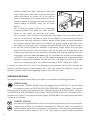
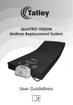
User Guidelines for Pressure Area Care Mattresses and Cushions QUATTRO ACUTE Systems ® QUATTRO PLUS Systems ® QUATTRO OVERLAY Systems ® PULSAIR CHOICE Systems ® SUPREMA™ DORMIRA™ B.A.S.E. Seating Systems ® Contents Page INTRODUCTION1 CAUTIONS AND WARNINGS INFORMATION 2 ALTERNATING AIR PRESSURE MATTRESSES & CUSHIONS INSTALLATION AND USER GUIDELINES CARE AND MAINTENANCE FAULT FINDING FOAM MATTRESSES & CUSHIONS INSTALLATION AND USER GUIDELINES CARE AND MAINTENANCE 3 8 9 11 11 SPECIFICATIONS13 EXPLANATION OF LABELS SYMBOLS AND STATEMENTS BACK COVER EMC MANUFACTURER’S DECLARATION BACK COVER Introduction Thank you for choosing to use a Talley Medical pressure area care product, effective for the prevention and management of pressure ulcers. The range of alternating air pressure products is as follows:lQUATTRO ACUTE: mattress replacement system for patients at very high risk of pressure ulcers ® lQUATTRO PLUS: mattress replacement system for patients at high risk of pressure ulcers ® lQUATTRO OVERLAY: mattress overlay system for patients at high risk of pressure ulcers ® lPULSAIR CHOICE mattress replacement: for patients at high risk of pressure ulcers ® lPULSAIR CHOICE mattress overlay: for patients at medium risk of pressure ulcers ® lPULSAIR CHOICE cushion: seat cushion: for patients at medium risk of pressure ulcers ® lB.A.S.E. SEQUENTIAL: seat cushion for patients at very high risk of pressure ulcers* ® lB.A.S.E. RECLINER MAT™: seat and back cushion for patients at very high risk of pressure ulcers* ® The range of static foam products is as follows:l SUPREMA™: mattress replacement and cushion for patients at medium risk of pressure ulcers l DORMIRA™: mattress replacement and cushion for patients at risk of pressure ulcers 1 Cautions and Warnings Before using alternating air pressure mattress / cushion systems ensure that: l the electricity supply is of the type indicated on the power unit l the mains lead is free from damage and is positioned so as not to cause an obstruction l the system is not used in the presence of flammable anaesthetics For 110V units only - means to isolate the power unit from the electricity supply shall be carried out via disconnecting the plug attached to the non-detachable mains cord from the wall socket. The equipment conforms to IEC 60601-1-2 for electromagnetic interference, however should the equipment be subjected to electromagnetic interference outside this then the unit should be recalibrated by a qualified service technician. Do not place mattress/cushion or power unit on or near a heat source. Do not use with hot water bottles or electric blankets. Although the materials used in the manufacture of all components of the mattress/cushion system comply to the required fire safety regulations, Talley Medical advise against smoking whilst the system is in use, to prevent the accidental secondary ignition of associated items which may be flammable, such as bed linen. In order for alternating air pressure mattress/cushion systems to operate effectively, please avoid placing objects on the surface that may obstruct the movement of air between the cells. For the same reason, please discourage people from sitting on the edge or on the end of the mattress whilst it is in use. Do not place heavy objects on the surface of foam mattresses when not in use. Do not allow sharp objects to penetrate the cover material. Do not store in damp conditions. The system is used as part of a pressure ulcer prevention programme, not solely relied upon for this purpose. Alternating pressure therapy should not be used for patients with unstable fractures, gross oedema, burns or an intolerance to motion. It should be noted that the use of a cushion will increase the patient's seated height by approximately 5cm, and care should be taken to ensure the patient's comfort and security regarding height of foot and arm rests. 2 Alternating Air Pressure Mattresses & Cushions Installation and User Guidelines INSTALLING MATTRESSES 1. If using a mattress replacement system, which is intended to completely replace the bed mattress, remove any existing mattress from the bed frame. If using a mattress overlay system, ensure bed frame to be used has an existing mattress in place. 2. Place the mattress on the bed frame/existing bed mattress. If using a powered mattress ensure the mattress hose exits at the foot end on the right hand side and the coloured cover is uppermost. 3. Secure the mattress to the bed frame/existing mattress using adjustable straps - pass straps beneath or around bed frame mattress platform/ bed mattress and secure with the buckles (Fig. 1), allowing for moving components on electric bed frames. This is important as it stops the mattress becoming detached from the bed frame/existing bed mattress and causing possible injury to the patient. A strap extension kit is available for use with divan beds (part number 97-50-10-153). 3 Fig. 1 Fig. 2 4. Suspend the power unit from the foot board of the bed having first adjusted the hanger brackets as instructed at the rear of the unit. Alternatively the power unit may be placed on the floor. 5. Attach the air supply hose to the power unit by aligning the black line on the air supply hose connector with the black line on the power unit connector and pushing together. Rotate the mattress hose connector clockwise until the green indicator fills the indicator hole on the power unit connector (Fig. 2). 6. Plug the smaller end of the power lead into the left hand side of the power unit, and the other end into mains outlet in wall. Ensure that the mains lead and tubing cannot become trapped in the bed frame. 7. Switch the power on at the outlet, and at the side of power unit adjacent to the power lead entry. 8. The system will display STARTING, then INITIALISING whilst the mattress inflates (this will take between 15 - 20 minutes). Note: It is important that during the INITIALISING phase the mattress connector is not disconnected from the power unit. If this is done, the power unit must be switched off, MUTE button pressed when the audible alarm is made, the mattress connector re-engaged, and the power unit restarted. If UNCALIBRATED is displayed when switched on, the system will continue to operate but should be recalibrated as soon as possible. 9. When a bottom sheet is added to the mattress, ensure that it is left loose to allow the mattress surface to conform with the patient's body as much as possible. 10. Allow the mattress to inflate before positioning the patient on the mattress. 11. Once inflated the system will automatically default to ACTIVE mode. CONTINUOUS LOW PRESSURE therapy can be selected via the THERAPY MODE button (please see THERAPY MODE on page 5). The comfort setting can be adjusted using the up and down arrow buttons (see COMFORT CONTROL on page 5). NB. The power unit will automatically lock 2 minutes after last button operation when running to prevent inadvertent operation of button functions (except MUTE), as indicated by ‘L’ on the display screen. Press and hold the MUTE/UNLOCK button until power unit beeps if further button operation is needed (i.e. change of therapy mode or comfort setting). 12. Place the carry bag and user manual in a safe place for future use. INSTALLING CUSHIONS The QUATTRO PLUS, QUATTRO OVERLAY AND PULSAIR CHOICE power units can all be used to operate their respective alternating air pressure cushions. Place the cushion on a chair, ensuring that it is placed the correct way up with the BACK labelling (if applicable) facing the back of the chair. Secure cushion to chair using adjustable straps, where available. ® ® ® 1. The PULSAIR CHOICE cushion is connected to the PULSAIR CHOICE power unit exactly as described in points 5. to 8. above and will take approx. 30 seconds to inflate. 2. The B.A.S.E. SEQUENTIAL and B.A.S.E. RECLINER MAT cushions can be used with the QUATTRO PLUS and QUATTRO OVERLAY mattress systems, either operated with the mattress or, using a cushion adaptor, directly with the power unit, as follows:- ® ® ® ® ® ® a)To use the cushion directly with the power unit, connect the cushion adaptor to the power unit, rotating the adaptor clockwise until the green indicator fills the indicator hole on the power unit connector. Connect the air supply hose from the cushion onto the adaptor, matching up the alignment markings (Fig. 3). Ensure that this has been Fig. 3 4 correctly clicked into place, otherwise a leak may Fig. 4 occur. Attach the power lead, plug into the mains outlet and switch the power on at the side of power unit adjacent to the power lead entry. Once inflated (approx. 5 minutes) increase the comfort control setting to SEATED using the UP arrow button. NB. If using the power unit from an operating mattress system, first press the MAX. INFLATE button to fully inflate the mattress, then rotate the air supply hose connector anti-clockwise and detach from the power unit to seal the air within the mattress to leave it fully inflated. To reconnect the mattress to the power unit after using the cushion, switch off the power unit and disconnect the cushion adaptor. Re-connect the mattress air supply tubing to the power unit, and switch on the power unit (operation will automatically default to Active mode). b)To use the cushion whilst the mattress is operating, simply attach the air supply hose from the cushion to the connection port on the side of the head end of the mattress by matching up the alignment markings and pushing together the CPC connectors until they click into place (Fig. 4), increasing the comfort control setting to SEATED. The mattress and cushion will operate simultaneously, allowing the simple transfer of the patient between the bed and chair. NB. When the patient is in bed, return the comfort setting to the mattress settings of SOFT, MEDIUM or FIRM. It should be noted that the use of an alternating air pressure cushion will increase the patient’s seated height by approximately 5cm, and care should be taken to ensure the patient’s comfort and security regarding height of foot and arm rests. OPERATION BUTTONS The operation buttons on the face of the power unit provide the following functions. THERAPY MODE Pressing the THERAPY MODE button will toggle between ACTIVE (1 in 4 alternating air pressure cycle) and CONTINUOUS LOW PRESSURE therapy modes. The selected therapy mode is shown on the display screen. The default mode is ACTIVE therapy. To switch to CONTINUOUS LOW PRESSURE mode, press THERAPY MODE button for 2 seconds until an audible tone is heard. The system will then display 'PLEASE WAIT' and requires approximately 2 minutes to initialise. COMFORT CONTROL Air pressure is regulated within each of the cells throughout the cycle so that support, posture and therapy are constantly maintained at optimum levels, in response to patient weight, movement and position. Equalisation of cell pressure automatically takes place at each stage of the 1-in-4 cycle, again to ensure precise pressure 5 and therapy is provided. The automatic default comfort setting is medium. However, if the patient prefers a firmer or softer mattress, increase or decrease the comfort control setting accordingly using the UP and DOWN arrow buttons (SOFT/MEDIUM/FIRM). The comfort setting is shown on the display screen. Check periodically to ensure patient support and comfort. DATA Pressing the DATA button at any time switches the display into DATA mode. Use the up and down arrow buttons to scroll through the product data and user information set. Pressing the DATA button again returns the display to the previous mode. NB. Used for accessing information only, does not affect mode of operation. MUTE/UNLOCK Press to silence the alarm and to clear the alarm display from the display screen. The power unit will automatically lock 2 minutes after the last button operation when running to prevent the inadvertent operation of button functions (except MUTE), as indicated by 'L' on the display screen. Press and hold the MUTE/UNLOCK button until the power unit beeps if further button operation is needed (i.e. comfort setting). The power unit will lock again 2 minutes after the last button operation. NB. After power failure/switching the power off, pressing MUTE cancels the system's previous settings. When power returns the default setting of ACTIVE mode, comfort setting 3 is invoked. (Note that previous settings are automatically cancelled if the duration between switch off and switch on is greater than 12 seconds. If power returns before a period of 12 seconds has passed and the MUTE button has not been pressed, the system will return to the previous mode of operation.) MAX. INFLATE Necessary for some nursing procedures, the MAX INFLATE mode inflates the mattress to maximum static pressure for a period of 15 minutes. After pressing the MAX INFLATE button to inflate mattress, the system displays 'PLEASE WAIT' followed by 'READY' and a 5 second audible tone when maximum pressure is achieved and 'MAX INFLATE' is shown on the display screen. After 15 minutes the system automatically returns to the Active mode of operation. MAXIMUM USER WEIGHT GUIDELINES QUATTRO ACUTE :- 250kg (39 stone) max. QUATTRO PLUS and PULSAIR CHOICE mattress replacement:- 200kg (31 stone) max. QUATTRO OVERLAY:- 160kg (25 stone) max. PULSAIR CHOICE mattress overlay:- 127kg (20 stone) max. B.A.S.E. SEQUENTIAL and B.A.S.E. RECLINER MAT cushions:- 127kg (20 stone) max. PULSAIR CHOICE cushion:- 102kg (16 stone) max. ® ® ® ® ® ® ® ® 6 CPR FACILITY (Fig. 5) The CPR device is situated at the head end on the right hand side of the mattress (viewed from foot end), as indicated by arrows on the mattress tag. For rapid deflation rotate the dial of the CPR device anti-clockwise to ‘click’ into the open position . If re-inflating the mattress, make sure the dial of the CPR device is rotated clockwise until it ‘clicks’ into the closed position . Fig. 5 PATIENT TRANSPORT FACILITY (Fig. 6) Press MAX. INFLATE button (if applicable) to fully inflate the mattress. When maximum pressure is achieved, detach the mattress air supply hose from the power unit by rotating the mattress hose connector anticlockwise until the black lines align, and pull the mattress hose connector away. The mattress will remain inflated, so supporting the patient. Fig. 6 All alternating air pressure mattresses can be used on profiling bed frames, slatted frames, in-filled frames and divans. Back rests or pillows for support should be placed beneath the mattress to allow uninterrupted body contact with the mattress surface. Place the bottom sheet loosely on the mattress to allow the mattress surface greater contact with the patient’s body. Avoid using fitted sheets. The use of incontinence sheets / excessive bedding beneath the patient may reduce the pressure relieving effect of the mattress. To remove air from the mattress when dismantling the system, use the CPR facility as described above. Care should be taken when raising and lowering bed safety side rails in order to avoid possible interference with the CPR and cushion connection port where fitted. A gap of 2.5cm on either side of the mattress should not be exceeded when side rails are deployed. 7 Care and Maintenance COVER Always keep the mattress/cushion cover as clean as is practicable. The material is waterproof and vapour permeable. l Inspect top cover for signs of damage or wear which could result in the contamination of the interior, e.g. tears, holes, damage to seams or zips, underside staining, etc. The frequency of these checks should be at each decontamination process, i.e. between patients or patient occupancy (or weekly for longer term patients). l Care should be taken to avoid puncturing cover with objects such as needles, scalpels, pat slides, acrylic nails, etc. l The cover may be removed and cleaned in accordance with The Revised Healthcare Cleaning Manual June 2009 subject to the following action: Following the use of a detergent and or disinfectant solution the mattress cover should be rinsed with clean water using a clean cloth and allowed to dry. l Frequent or prolonged exposure to high concentrations of agressive disinfectant solutions will reduce the useful life of the mattress/cushion cover. l Where high concentration disinfectants e.g. > 10,000ppm chlorine releasing agent (e.g. Haztab or bleach) or combined cleaning/chlorine releasing agent (e.g. Chlorcleam, Actichlor) and detergent solutions are used to remove blood or other body fluids, mattresses/cushions should be thoroughly rinsed with clean water to remove any residues. This will help prevent any possible long term compatibility issues associated with disinfectant residues. l Alternatively disinfection may be achieved by laundering at temperatures not exceeding 65 C for 10 minutes or 73 C for 3 minutes which may include a chlorine rinse. l Do not use abrasive cleaners, phenol disinfectants, solvents or alcohol-based cleansers, e.g. Dettol, Phenicol, Hibiscrub, Clearsol, Stericol, Hycoline, as these will destroy the cover materials. l Do not iron. l Ensure that the mattress/cushion is thoroughly dried before remaking the bed or placing in storage. 0 0 INTERIOR COMPONENTS l Check air cells and mattress/cushion interior for signs of damage or contamination, e.g. staining or evidence of fluid ingress. The frequency of these checks should be at each decontamination process, i.e. between patients or patient occupancy (or weekly for longer term patients) l Care should be taken to avoid puncturing air cells with objects such as needles, scalpels, pat slides, acrylic nails, etc. l The individual cells can also be wiped clean with a mild antiseptic solution. l All cells are replaceable and can be obtained easily from Talley Medical. l Do not immerse the PULSAIR CHOICE mattresses/cushion in water. l The QUATTRO range of mattresses are fully launderable, but ensure the CPR device is fully closed (i.e. the dial of the CPR device is rotated clockwise until it ‘clicks’ into the closed position ), prior to laundering to prevent water entering the air cells / tubing. ® ® 8 POWER UNIT Always disconnect the power unit from the electricity supply before cleaning. Power units can be wiped down with a detergent or disinfectant solution or wipe. Do not use solvents. The unit contains no user serviceable parts, and should only be serviced by a competent electrical engineer, or returned to Talley Medical / your local authorised dealer. All Talley Medical products should be serviced every two years by Talley Medical or authorised dealer in order to comply with warranty conditions. It is the customer’s responsibility to ensure the following prior to collection: l the system is cleaned of any obvious contaminants. l contamination status is documented. l assistance is given to Talley Medical personnel to bag the equipment if the mattress has been in a known or suspected infectious environment. SYSTEM DESIGN LIFE: 5 years HANDLING AND STORAGE Handle with care. Please report instances of damage or impact to Talley Service Department. Temperature: Operational: 10 C to 40 C Storage: 10 C to 55 C Humidity and other environmental conditions: refer to the Service Manual. o o o o TRANSPORTATION OF MATTRESS SYSTEM The mattress should be loosely rolled lengthwise with the cover innermost, taking care not to strain the umbilical. It can then be transported and stored in the carry bag with the power unit, mains cable and this booklet. Do not stack bagged mattresses more than two high to avoid strain on the umbilical. Fault Finding All alarms can be reset by pressing the MUTE button once. This also cancels the fault displays. MUTE also silences the audible alarm. All systems have a fault log that records the last 5 faults via the DATA display mode. If problems reoccur contact Talley Medical. AC FAIL fault – indicates a mains power failure, an audible alarm will sound if power is interrupted, e.g. power unit switched off, power cut, disconnection of mains lead. Press MUTE or re-connect to power supply. ROTOR SYSTEM fault – indicates the automatic sequential cycle has stopped or there is a fault in the system. Switch power off, press MUTE button, then switch power on again. If the fault re-occurs, contact Talley Medical. 9 LOW PRESSURE warning – will alert if pressure falls below the minimum allowable levels. Check that the hose is connected to the power unit correctly. Check that the CPR device is fully closed, i.e. the dial of the CPR device is rotated clockwise until it ‘clicks’ into the closed position . Check that the internal cells are connected and that no cell is punctured. Press the MUTE button to clear alarm. Note that the alarm will reoccur if the fault persists, if the fault re-occurs, contact Talley Medical. EMI fault – indicates that the unit detects the pressure sensor amplifier is adversely affected by external RF fields. This will clear when interference ceases. OTHER ALARMS PUMP OR TRIAC fault - indicates a pump control failure or an open pump coil fault. Should this occur, contact Talley Medical. UNCALIBRATED - contact Talley Medical for recalibration. If you have any queries relating to this system please contact Talley Medical or your local authorised dealer. 10 Static Foam Mattresses Installation and User Guidelines MATTRESSES 1. Ensure the bed frame to be used has no existing mattress components, and is free from items which could cause damage to the SUPREMA™ / DORMIRA™ mattress. It should be noted that this mattress is intended to completely replace the existing mattresses. 2. Place the SUPREMA™ / DORMIRA™ mattress on the bed frame. NB. If using the SUPREMA™ mattress ensure that the mattress is positioned with the printed cover uppermost with the grey, non-slip base facing downwards. 3. Place the user manual in a safe place for future use. The SUPREMA™ / DORMIRA™ mattress can be used on profiling bed frames, slatted frames, in-filled frames and divans. A gap of 2.5cm either side of the mattress should not be exceeded when side rails are deployed. CUSHIONS Place the SUPREMA™ / DORMIRA™ cushion onto a chair. If using the SUPREMA™ cushion ensure that it is positioned with the green cover uppermost with the grey, non-slip base facing downwards. N.B. It should be noted that the use of a foam cushion will increase the patient’s seated height by approximately 5cm, and care should be taken to ensure the patient’s comfort and security regarding height of foot and arm rests. Care and Maintenance The SUPREMA™ / DORMIRA™ mattress/cushion will provide years of efficient service if it is cared for in the following way: COVER Always keep the mattress/cushion cover as clean as is practicable. The material is waterproof and vapour permeable. 11 l Inspect top cover for signs of damage or wear which could result in the contamination of the interior, e.g. tears, holes, damage to seams or zips, underside staining, etc. The frequency of these checks should be between patients or patient occupancy (weekly for longer term patients) l Care should be taken to avoid puncturing cover with objects such as needles, scalpels, pat slides, acrylic nails, etc. l The cover may be removed and cleaned in accordance with The Revised Healthcare Cleaning Manual June 2009 subject to the following action: Following the use of a detergent and or disinfectant solution the mattress cover should be rinsed with clean water using a clean cloth and allowed to dry. l Frequent or prolonged exposure to high concentrations of aggressive disinfectant solutions will reduce the useful life of the mattress/cushion cover. l Where high concentration disinfectants e.g. > 10,000ppm chlorine releasing agent (e.g. Haztab or bleach) or combined cleaning/chlorine releasing agent (e.g. Chlorcleam, Actichlor) and detergent solutions are used to remove blood or other body fluids, mattresses/cushions should be thoroughly rinsed with clean water to remove any residues. This will help prevent any possible long term compatibility issues associated with disinfectant residues. l Alternatively disinfection may be achieved by laundering at temperatures not exceeding 65 C for 10 minutes or 73 C for 3 minutes which may include a chlorine rinse. l Do not use abrasive cleaners, phenol disinfectants, solvents or alcohol-based cleansers, e.g. Dettol, Phenicol, Hibiscrub, Clearsol, Stericol, Hycoline as these will destroy the cover materials. l Do not iron. l Ensure that the mattress/cushion is thoroughly dried before remaking the bed or placing in storage. 0 0 INTERIOR l Inspect the mattress/cushion interior for signs of damage or contamination, e.g. staining or evidence of fluid ingress. The frequency of these checks should be at each decontamination process, i.e. between patients or patient occupancy (or weekly for longer term patients) l Contaminated mattresses/cushions should be removed from service and disposed of in accordance with local policy. l Regular turning will prolong the life of the mattress. The SUPREMA™ has a 2 way turning cycle and the DORMIRA™ has a 4 way turning cycle. Please refer to instructions printed on cover. SYSTEM DESIGN LIFE: 3 years HANDLING AND STORAGE Handle with care. Please report instances of damage or impact to Talley Service Department. The mattress should be stored flat. Temperature: Operational: 10 C to 40 C Storage: 10 C to 55 C 0 0 0 0 12 TRANSPORTATION OF MATTRESS SYSTEM The mattress should be transported flat and not rolled. Mattresses should not be stored more than 6 high as this can potentially be a safety hazard when handling. To protect the covers, mattresses should be packed in minimum 200 micron clear polythene. Specifications ALTERNATING AIR PRESSURE POWER UNITS Construction: ABS Plastic Dimensions:335mm/13.2” x 233mm/9.2” x 165mm/6.5” Weight: 3.4 kg / 7.5 lbs Mains Cable: 5 metres / 16.5’ Electricity Supply: 240V ~ 50Hz USA:- 110V ~ 60Hz Saudi Arabia: 240V ~ 60Hz Full Load Wattage: 12W Fuse Rating: 2 x 500mA Cycle Time: QUATTRO ACUTE: variable (continuous) QUATTRO PLUS: 15 minutes (continuous) QUATTRO OVERLAY: 15 minutes (continuous) PULSAIR CHOICE: 15 minutes (mattress replacement) / 10 minutes (mattress overlay/cushion) (continuous) ® ® ® ® ALTERNATING AIR PRESSURE MATTRESSES BASE: QUATTRO ACUTE / QUATTRO PLUS / QUATTRO OVERLAY: Woven nylon 940 DTEX PU coated both sides PULSAIR CHOICE: PVC coated 2oz nylon, 350 micron CELLS: PU film COVER: PU coated stretch nylon 255g/m Options: Standard / Long / Narrow Type:QUATTRO ACUTE / QUATTRO PLUS / PULSAIR CHOICE MATTRESS REPLACEMENT: Orthodifferential TISSUEgard™ pleated air cells operating in a 1-in-4 alternating air pressure cycle QUATTRO OVERLAY: Orthodifferential air cells operating in a 1-in-4 alternating air pressure cycle PULSAIR CHOICE mattress overlay: Orthodifferential air cells operating in a 1-in-2 alternating air pressure cycle DimensionsQUATTRO ACUTE: 1980mm x 880mm x 240mm (UK standard size) QUATTRO PLUS/PULSAIR CHOICE MATTRESS REPLACEMENT: 1950mm x 880mm x 180mm QUATTRO OVERLAY: 1930mm x 855mm x 130mm Construction: ® ® ® ® 2 ® ® ® ® ® ® ® 13 ® ® PULSAIR CHOICE MATTRESS OVERLAY: 1930mm x 855mm x 130mm Weight:QUATTRO ACUTE: 12.5kg; n QUATTRO PLUS: 9.4kg n QUATTRO OVERLAY: 6.3 kg; n PULSAIR CHOICE: 8.0kg (mattress replacement) / 5.5kg (mattress overlay) ® ® ® ® ® ALTERNATING AIR PRESSURE CUSHIONS BASE: B.A.S.E. SEQUENTIAL / RECLINER MAT cushion: Woven nylon 940 DTEX PU coated both sides n PULSAIR CHOICE cushion: PVC coated 2oz nylon, 350 micron INNER: B.A.S.E. SEQUENTIAL / RECLINER MAT cushion: PVC bellows within punched CMFR foam n PULSAIR CHOICE cushion: PU film COVER: PU coated stretch nylon 255g/m2 Type:B.A.S.E. SEQUENTIAL / RECLINER MAT cushion: 8/20 rows of 6 bellow cell strips operating in a 1-in-4 alternating air pressure cycle PULSAIR CHOICE cushion: One piece air cell set operating in a 1-in-2 alternating air pressure cycle DimensionsB.A.S.E. SEQUENTIAL cushion: 430mm x 430mm x 70mm (UK standard size) B.A.S.E. RECLINER MAT™ cushion: 1080mm x 430mm x 70mm PULSAIR CHOICE cushion: 430mm x 430mm x 40mm Weight:B.A.S.E. SEQUENTIAL cushion: 1.9kg; n B.A.S.E. RECLINER MAT cushion: 3.9kg n PULSAIR CHOICE cushion: 1.3kg Construction: ® ® ® ® ® ® ® ® ® ® ® ® STATIC FOAM MATTRESSES & CUSHIONS Construction:SUPREMA™ mattress/cushion: 57-63kg/m density viso-elastic foam over a base of 38-42 kg/m nominal density / 150-190N nominal hardness SAFEGUARD CMHR DORMIRA™ mattress/cushion: Multi-layered SAFEGUARD CMHR foam: 38-42 kg/m nominal density / 110-140N / 100-130N nominal hardness Cover: PU coated stretch nylon 255g/m DimensionsSUPREMA™ mattress: 1970mm x 880mm x 160mm SUPREMA™ cushion: 432mm x 432mm x 76mm DORMIRA™ mattress: 1970mm x 880mm x 127mm DORMIRA™ cushion: 432mm x 432mm x 76mm Weight:SUPREMA™ mattress/cushion: 13.5kg / 1.0kg DORMIRA™ mattress/cushion: 10.0kg / 0.9kg Turning cycle: SUPREMA™ mattress/cushion: 2 way DORMIRA™ mattress/cushion: 4 way 3 3 3 2 MANUFACTURER'S GUARANTEE All power units, alternating mattresses/cushions and foam mattresses/cushions are covered by a 24 month manufacturer's guarantee. 14 EXPLANATION OF LABEL SYMBOLS AND STATEMENTS ATTENTION Consult accompanying documents WARNING This is a statement that alerts the user to the possibility of serious injury or other adverse reactions with the use or misuse of the device CAUTION This is a statement that alerts the user to the possibility of a problem with the system associated with its use or misuse Medical Devices Directive 93/42/EEC Electrical Protection Type B Class II Equipment (Double Insulated) This product is CLASSIFIED by Underwriters Laboratories Inc. with respect to electric shock, fire and mechanical hazards only in accordance with UL60601-1 and CAN/CSA-C22.2 No. 601.1 Do not dispose of with the normal household waste (please refer to www.talleygroup.com for further details) EMC MANUFACTURER’S DECLARATION Class A industrial 55001 Manufacturers declaration - Electromagnetic Emissions Model Type 19 is intended for use in the electromagnetic environment specified below. The customer or user of the Type 19 systems should assure that it is used in such an environment. Emissions Test RF emissions CISPR 11 Harmonics emissions 61000-3-2 Voltage Fluctuations/Flicker emissions 61000-3-3 Compliance Class B Class A Complies Electromagnetic environment - guidance The Type 19 systems are suitable for use in all establishments, including domestic establishments and those directly connected to the public low-voltage power supply network that supplies buildings used for domestic purposes Manufacturers declaration - Electromagnetic Immunity The Type 19 systems are intended for use in the electromagnetic environment specified below. The customer or user should assure that it is used in such an environment IEC 60601 Electromagnetic environment Immunity test Compliance level Test Level guidance Electrostatic discharge (ESD) ± 6kV contact ± 6kV contact Floors should be wood, concrete or ceramic tile. If floors IEC 61000-4-2 ± 8Kv air ± 8Kv air are covered with synthetic material, the relative humidity should be at least 30% Electrical fast transient/burst IEC 61000-4-4 ± 2 Kv For power supply lines ± 1kV For input/output lines ± 2 Kv For power supply lines ± 1kV For input/output lines Mains power quality should be that of a typical commercial hospital environment Surge IEC61000-4-5 ± 1kV line(s) to line ± 1kV line(s) to line Mains power quality should be that of a typical commercial hospital environment Voltage dips, short interruptions and voltage variations on power supply input lines IEC 61000-4-11 <5 %Ur (>95 %Ur) for 0.5 cycle 40 %Ur (60% dip in Ur) for 5 cycles 70 %Ur (30% dip in Ur) for 25 cycles >5 %Ur (>95 % dip in Ur) for 5 seconds <5 %Ur (>95 %Ur) for 0.5 cycle 40 %Ur (60% dip in Ur) for 5 cycles 70 %Ur (30% dip in Ur) for 25 cycles >5 %Ur (>95 % dip in Ur) for 5 seconds Mains power quality should be that of a typical commercial hospital environment. If the user of the Type 19 system requires continued operation during power mains interruptions', it is recommended that the Type 19 be powered from an uninterruptible power supply or a battery Power frequency (50/60Hz) magnetic field IEC61000-4-8 3 A/m 3 A/m Power frequency magnetic fields should be at levels characteristic of a typical location in a typical commercial or hospital environment USER MANUAL PART NUMBER 50-02-07-200/3 TALLEY GROUP LIMITED Premier Way, Abbey Park Industrial Estate, Romsey, Hampshire SO51 9DQ England Web: www.talleygroup.com Europe re-order:- (0)1794 503500 USA re-order:- Talley USA 888-259-9994 04/2012