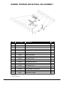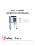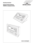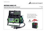
1
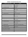
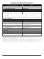
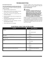
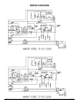
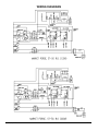
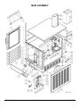
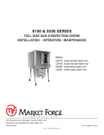
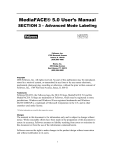
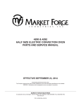
st-5g
gas countertop convection steamer
parts and service manual
Effective june 12, 2015
Superseding All Previous Parts Lists.
The Company reserves the right to make substitution in the event that items specified are not available.
ERRORS: Descriptive and/or typographic errors are subject to correction.
MARKET FORGE INDUSTRIES
44 Lakeside Avenue, Burlington, Vermont 05401 USA Telephone: (802) 658-6600 Fax: (802) 860-3732
www.mfii.com
P/N 14-0287 Rev C
Table of Contents
General Troubleshooting Guide. . . . . . . . . . . . . . . . . . . . . . . . . . . . . . . . . . . . . . . . . . . . . . . . . 3
troubleshooting.. . . . . . . . . . . . . . . . . . . . . . . . . . . . . . . . . . . . . . . . . . . . . . . . . . . . . . . . . . . . . . . . . . 5
Electrical Fault Isolation GUide. . . . . . . . . . . . . . . . . . . . . . . . . . . . . . . . . . . . . . . . . . . . . . . . . 6
Wiring Diagrams. . . . . . . . . . . . . . . . . . . . . . . . . . . . . . . . . . . . . . . . . . . . . . . . . . . . . . . . . . . . . . . . . . . . 7
illustrated parts list
Main Assembly. . . . . . . . . . . . . . . . . . . . . . . . . . . . . . . . . . . . . . . . . . . . . . . . . . . . . . . . . . . . . . . . . . . . . . . 9
Door Assembly. . . . . . . . . . . . . . . . . . . . . . . . . . . . . . . . . . . . . . . . . . . . . . . . . . . . . . . . . . . . . . . . . . . . 12
Burner, Propane and Natural Gas Assembly. . . . . . . . . . . . . . . . . . . . . . . . . . . . . . . . . . 13
Gas Plumbing and Valve Assembly. . . . . . . . . . . . . . . . . . . . . . . . . . . . . . . . . . . . . . . . . . . . . . 14
june 12, 2015
2st-5g
General Troubleshooting Guide
PROBLEM / PROBABLE CAUSE
REMEDY
1. 1. Cooking Indicator Light Fails to Light with Timer Set.
a. Main power circuit breaker tripped.
Located external circuit breaker for incoming power and
place in ON position.
b. Door interlock switch contacts not closed.
Shut cooker door to close switch contacts. Check alignment
of door with switch.
c. Door interlock switch faulty.
Replace switch.
d. Indicator light burned out.
Replace light.
e. Faulty timer contacts.
Replace timer.
f. Faulty wiring.
Inspect condition of wire and tightness of all connections.
Correct as needed.
2. Steam Fails to Enter Cooking Compartment with Cooking Indicator Light On.
a. Faulty wiring.
Inspect condition of wire and tightness of all connections. Correct
as needed.
3. Steam Enters Compartment Continuously. Timer Dial Not Turning.
a. Constant steam position.
Move knob to timing location.
b. Faulty thermostatic switch.
Replace switch.
c. Faulty timer motor.
Replace timer.
d. Faulty wiring.
Inspect condition of wire and tightness of all connections.
Correct as needed.
4. Steam Continues to Flow into Compartment and/or Buzzer Fails to Sound at End of Timer Setting.
a. Faulty timer contacts.
Replace timer.
b. Faulty buzzer.
Replace buzzer.
c. Faulty wiring.
Inspect condition of wire and tightness of all connections.
Correct as needed.
5. Steam Flows Continuously from Boiler Drain Line with Cooker in Operation.
a. Cold water not connected.
Turn on external shut-off valve.
b. Faulty cooling valve.
Replace cooling valve.
c. Faulty wiring.
Inspect condition of wire and tightness of all connections.
Correct as needed.
6. Door Leaks.
a. Damaged door gasket.
Check gasket for cuts and replace as needed.
b. Clogged compartment drain or plumbing.
Remove screen and clean drain line or plumbing.
7. Water Flows into Cooking Compartment.
a. Level probe short circuited.
Check and correct.
b. Scale build-up on probe.
Clean all probes.
c. Water fill solenoid valve.
Plugged, defective, clean or replace.
8. Water Accumulates in Compartment.
a. Plugged compartment drain.
Remove screen and clean drain line.
9. Water Flows into Drain During Shut-Down.
a. Cooling valve does not close.
june 12, 2015
Check valve for foreign material or damage.
3st-5g
General Troubleshooting Guide
PROBLEM / PROBABLE CAUSE
REMEDY
10. Water not Being Supplied to Generator.
a. Water supply off.
Check incoming water valve is on.
b. Supply water pressure too low.
Call supply agency.
c. Defective water solenoid valve.
Replace or clean.
d. Level probe shorted.
Check and correct.
e. Defective water level control.
Replace.
f. Drain valve is open.
Check valve, clean or replace.
IMPORTANT NOTE: These problems are an indication of severe water conditions which should be corrected immediately
to avoid damage to the components and performance of the steamer. Call your Service Agency for Assistance.
ADJUSTMENTS: All units are adjusted at the factory. in case of operation problems at initial installation, check type of gas
supply and manifold pressure and compare it with information on the rating plate.
11. Burners Do Not Come On.
a. Gas supply is off.
Locate supply line and turn on.
b. Power switch is off.
Located switch in cabinet and turn on.
c. Probe not sensing water level.
Clean probes, check wiring.
d. Ignitor not functioning.
Check ignition module relay.
e. Combination gas valve not opening.
Check that control knob is in the ON position, check that
120 volts is at the gas valve.
12. Burners Produce Carbon Deposits.
a. Incorrect orifice size.
Check size and correct.
b. Incorrect gas supply.
Check size and correct.
c. Incorrect gas pressure.
Check gas pressure at manifold. Correct if necessary.
13. Flash Back.
a. Burning inside mixer tube.
Reduce primary air.
b. Incomplete combustion.
Increase burner input.
c. Sooting of burner.
Increase primary air.
d. Miss-located ignitor.
Adjust ignitor.
IMPORTANT NOTICE: AT LEAST TWICE A YEAR, HAVE AN AUTHORIZED SERVICE PERSON CLEAN AND ADJUST
THE UNIT FOR MAXIMUM PERFORMANCE.
ADJUSTMENTS AND SERVICE WORK MAY BE PERFORMED ONLY BY A QUALIFIED TECHNICIAN WHO IS EXPERIENCED IN AND KNOWLEDGEABLE WITH THE OPERATION OF COMMERCIAL GAS COOKING EQUIPMENT.
HOWEVER, TO ASSURE YOUR CONFIDENCE, CONTACT YOUR AUTHORIZED SERVICE AGENCY FOR RELIABLE
SERVICE, DEPENDABLE ADVICE OR OTHER ASSISTANCE AND FOR GENUINE FACTORY PARTS.
june 12, 2015
4st-5g
troubleshooting
Finding, Understanding and fixing the Problem
Timer Contacts (60 Minute Timer)
Defective timer contacts will result in failure of cooker
compartment to operate. When this occurs, remove the
control pan and proceed as follows:
1. Turn off power to the cooker at external circuit breaker.
Door Interlock Switch
Malfunction of the cooker door interlock switch prevents
timer indicator light from turning on and steam solenoid
from opening when the timer dial is set. If steam does not
enter the compartment and the cooking indicator light fails
to turn on with the door latch securely engaged, the fault
may be in the door interlock switch. Proceed as follows:
1. Turn off power to the cooker.
2. Disconnect all five wires from timer terminals.
2. Disconnect wire to the door switch terminals.
3. Connect an ohmmeter terminals 1 and 3.
3. Connect an ohmmeter between the terminals of the
switch.
4. Rotate timer dial beyond the “0 minute” point (any
setting) to obtain a reading of zero ohms on the
ohmmeter. If zero ohm reading cannot be obtained,
timer contacts are defective and the timer must be
replaced.
5. Move ohmmeter leads to terminals 1 and 4.
6. Rotate timer dial to “0 minute” position (an audible
click indicates correct position). If zero ohm reading
cannot be obtained, timer contacts are defective and
the timer must be replaced.
7. Remove ohmmeter and replace all five leads on timer
terminals.
Timer Motor (60 Minute Timer)
A defective timer motor will cause continuous operation
in the TIME mode, with the timer dial failing to return to
the “0 minute” position. Carefully check motor condition,
proceed as follows:
1. Carefully check motor wire leads and tighten lose
connections. !! WARNING: !! Use care while
working with control panel. Terminals
carry 120 Volts.
2. Turn on power to the steamer.’
3. Set timer dial (any setting beyond “0 minute”). If operation s correct, the motor will turn the dial toward “0
minute”. If the motor fails to operate, it is defective
and the entire timer must be replaced.
4. Shut off power to the cooker.
june 12, 2015
4. Actuate the switch by closing the cooking compartment door. If zero ohm reading cannot be obtained,
timer contacts are defective and the timer must be
replaced.
5. Remove the ohmmeter and replace the leads on
switch terminals.
Indicator Lights
If the cooker compartment functions correctly, with the
single exception that the indicator light fails to light during
operation, the fault is a defective indicator light. A “burned
out” or defective light is verified by using a AC volt-meter
at the leads, with input power on the selector switch in
correct position for that timer, the timer set, and the door
latches closed. If 120 volts is present, the fault is in the
indicator light and requires replacement. If 120 volts is
not present, the fault is in the wiring control components
(selector switch, timer or door switch).
Buzzer
If the buzzer does not sound at the termination of the operator-selected timer setting (timer dial returned to “0 minute” position), the fault may be a defective buzzer. Buzzer
operation os verified using an AC volt-meter at buzzer coil
connections with input power on a selector switch and coinciding timer dial set at the “0 minute” position. If voltage
is 120 volts, the fault is in the buzzer, which must be replaced. If 120 volts is not present, the fault is in the wiring
control components (selector switch or timer).
Wiring
Using an ohmmeter, wiring continuity between the connections shown on the wiring diagram is readily verified.
This is best done in stages, removing only those wires
required for each continuity check. As each lead is replaced, it should be checked for evidence of corrosion and
cleaned if necessary. All leads must be tightly attached so
as to provide a good electrical connection.
5st-5g
troubleshooting
Door Gasket Replacement
Door may be difficult to close until the gasket has compressed to conform to the door opening. Leaving door
closed overnight will compress gasket.
The cooking compartment door gaskets are made of silicone-type rubber material that is very durable, but subject
to wear during normal operation. Should the gasket leak
replace it as follows:
Exterior Panel Removal
warning
1. Open the cooking compartment door.
TO PREVENT HAZARD IN SERVICING THE
COOKER, BE CERTAIN THAT THE STEAM
SUPPLY BOILER IS SHUT DOWN, THE COLD
WATER SHUT-OFF VALVE IS CLOSED, AND
THE ELECTRICAL DISCONNECT CIRCUIT
BREAKER FOR THE COOKER/BOILER UNIT IF
OFF BEFORE REMOVING SIDE PANELS.
2. Remove the four screw on the outside of the door
frame and remove the door panel assembly.
3. Remove the six screw from the gasket plate in the
door panel assembly.
4. Remove the gasket plate and the door gasket from
the door panel.
Access to all internal plumbing and electrical assemblies
is from the right side. The right side panel is removed by
removing the bottom screws and pushing up on the panel
until the lower lip disengages from the frame. Gas control
is located on the right side behind the bottom panel. Remove the four screws.
5. Install the new door gasket to the door panel. Replace
the gasket plate and six screws.
6. Reassembly the door panel assembly in the door
frame using the four screws.
7. Gasket replacement is now complete.
Electrical Fault Isolation GUide
FAILURE
FAULT LOCATION
Will not operate in either CONSTANT STEAM or 60 MINUTE TIMER
positions.
a. Incoming power.
b. Timer.
c. Door interlock switch.
d. Wiring.
Operating in CONSTANT STEAM position, but not in 60 MINUTE TIMER position.
a. 60 minute timer.
Operates in 60 MINUTE TIMER position, but not in CONSTANT
STEAM position.
a. Timer.
With indicator light on and steam solenoid valve open, timer dial fails
to turn.
a. Constant steam position.
b. Wiring.
b. Wiring.
b. Timer motor.
c. Wiring.
BUZZER fails to sound at the end of 60 MINUTE TIMER mode.
a. 60 minute timer.
b. Buzzer.
c. Wiring.
Steam flows continuously from boiler drain line.
a. Cooling valve needs replacing.
b. Wiring.
june 12, 2015
6st-5g
Wiring Diagrams
june 12, 2015
7st-5g
Wiring Diagrams
june 12, 2015
8st-5g
Main Assembly
june 12, 2015
9st-5g
main assembly
item
part number
description
1
97-6364
HINGE ROD
1
2
97-6173
DOOR ASSEMBLY
1
qty.
3
97-6175
PAN RACK
2
4
97-6183
LEFT HAND SIDE AND BACK PANEL
1
5
97-6340
RACK PIN ASSEMBLY
4
6
97-6300
STEAM DIVERTER
2
7
~NPN~
HEX NUT
1
8
~NPN~
LOCK WASHER
1
9
97-6302
WASHER
1
10
97-6178
STRIKER
1
11
97-6184
CONTROL LEXAN
1
12
97-6170
PILOT LIGHT - GREEN
2
13
97-6171
PILOT LIGHT - RED
1
14
98-6046
DIAL
1
15
97-6365
COMPARTMENT STRAINER
1
16
97-6177
PERFORATED DOOR TROUGH
1
17
97-6185
OPERATION INSTRUCTION DECAL
1
18*
97-6186
FUSE, 2A, 250V (120V UNIT)
1
18*
98-6134
FUSE, 1A, 250V (220V UNIT)
1
19
97-5864
FUSE HOLDER
1
20
97-6179
DIAL
1
21
97-5048
OPERATING THERMOSTAT
1
22
97-6366
COMPONENT MOUNTING BOARD
1
23
97-6172
RELAY
2
24
97-6367
POWER SWITCH
1
25
97-6190
BUZZER
1
26
10-6962
END SECTION
1
26
10-6963
TERMINAL BLOCK SECTION
2
27
97-5052
GROUND LUG
1
28*
97-6194
LEVEL CONTROL, 10K, OHM, 120V
1
28*
97-6200
LEVEL CONTROL, 1 M, OHM (OPTIONAL)
2
29
97-6913
IGNITION MODULE, INTERMITTENT PILOT
1
30
97-6193
RELAY, DPDT
1
31
~NPN~
SCREW, 10-32 x 1/2
17
32
97-6201
RIGHT PANEL
1
33
97-6188
ELBOW, 3/8 C x 1/8 MPT
2
33A
98-6089
ELBOW, 1/4 C x 1/8 MPT
1
34
98-6123
CONNECTOR, 1/4 C x 1/8 MPT
1
35
97-6282
SOLENOID VALVE
2
36
97-5702
CORD SET, 120V
1
37
97-6191
DOOR SWITCH
1
37
97-6301
SWITCH ACTUATOR C/W CLIP
1
june 12, 2015
10st-5g
main assembly
item
part number
description
38
08-6464
TIMER
2
39
97-6331
HOSE BARB ELBOW, 1/2 C x 1/4 MPT
1
qty.
40*
97-7100
STEAM HOSE 1/2 x 13”
1
41A
97-6262
GENERATOR TANK
1
41B
97-6436
ELBOW 5/8C x 3/8 MPT
1
41C
97-7102
DRAIN TUBE
42
97-6196
HIGH LIMIT SENSOR
1
43
97-6208
ELBOW, 1/2 C x 3/4 MPT
1
44
97-6210
BLOWDOWN SOLENOID
1
45
97-6209
CONNECTOR, 5/8 C x 3/4 MPT
1
46
97-6368
DOWN TUBE
1
47
97-6202
ELBOW, 3/4
1
48
97-6369
NIPPLE, 3/4 x 2 1/2
1
49
97-6219
RELIEF VALE, 5 PSI
1
50
97-6217
TOP COVER
1
51
97-6370
CAP, 3/4
1
52
97-6371
NIPPLE, 3/4 X 3 1/2
1
53
97-6203
TEE, 3/4
1
54
97-6204
CLOSE NIPPLE, 3/4
1
55
97-6212
PROBE- LOW LEVEL CUT OFF
1
56
97-6372
PROBE-HIGH LEVEL
1
57
976213
PROBE-LOW LEVEL
1
58
97-6215
FLUE ASSEMBLY
1
59
97-6216
FLUE COVER ASSEMBLY
1
60
~NPN~
SCREW, 1/4-20 x 1/2
6
61
98-6047
ROTARY SHAFT SEAL
1
62**
97-6223
RIGHT HAND SIDE RISER
1
*
97-6222
LEFT HAND SIDE RISER
1
63
97-6220
FRONT RISER
1
*
97-6221
REAR RISER
1
64
97-6211
APPLIANCE LEG
4
65*
97-7103
HOSE CLAMP
4
66*
97-7104
HOSE BARB, 1/2 x 1/4 MPT
1
67*
97-6207
ELBOW, 1/2C x 1/4 MPT
1
68*
97-5701
TRANSFORMER, 115-24
1
69
97-6225
WIRE HARNESS
1
70*
97-5619
THERMOSTAT BULB FITTING
1
71*
97-6226
WATER SUPPLY CONNECTOR
2
72*
98-6138
TRANSFORMER, 100VA, 200-240/120V, (220V UNITS)
1
* Not Shown.
** Select as Required.
june 12, 2015
11st-5g
Door Assembly
june 12, 2015
item
part number
description
qty.
1
97-6227
DOOR FRAME
1
2
97-6231
DOOR HANDLE ASSEMBLY
1
--
97-6235
DOOR HANDLE DECAL
1
3
97-6232
LATCH ASSEMBLY
1
4
97-6261
BUSHING SPACER
4
5
97-6236
UPPER & LOWER SPACER
6
97-6230
DOOR PANEL
1
7
97-6228
DOOR GASKET
1
8
97-6229
GASKET PLATE
1
9
97-6233
GASKET PANEL SCREWS
8
10
97-6173
DOOR ASSEMBLY
1
1 ea.
12st-5g
Burner, Propane and Natural Gas Assembly
item
part number
1
~NPN~
HEX SHELF TAPPING SCREW, 8-32 x 1/4
4
2**
97-6244
PILOT BURNER, LIQUID PROPANE
1
97-6465
PILOT BURNER, NATURAL GAS
1
3
97-6245
BURNER MOUNTING BRACKET
1
4
~NPN~
MACHINE SCREW, 10-32 x 3/8
2
5
~NPN~
MACHINE SCREW, 10-32 x 1/4
2
6
97-6237
SPARK ELECTRODE
1
7
97-6533
PILOT TUBE
1
8
98-6124
PIPE PLUG, 1/8 MPT
1
9**
97-6239
GAS MANIFOLD ASSY, NATURAL GAS
1
97-6247
GAS MANIFOLD ASSY, L.P.
1
10
~NPN~
HEX CAP SCREW, 1/4-20 x 1/2
2
11**
97-6535
JET ORIFICE, #64, L.P.
4
97-6498
JET ORIFICE, #53, NATURAL GAS
4
97-6238
TWIN BURNERS, NATURAL GAS
2
97-6246
TWIN BURNERS, L.P.
2
~NPN~
SHEET METAL SCREW
4
12**
13
description
qty.
* Not Shown.
** Select as Required.
june 12, 2015
13st-5g
Gas Plumbing and Valve Assembly
item
part number
description
qty.
1
97-6249
BALL VALVE, 3/4
1
2
~NPN~
SCREW, #10-32 x 1/2
2
3
97-6250
GAS SUPPLY PIPE ASSEMBLY
1
4
98-6112
REDUCING COUPLING
1
5
97-6251
90 STREET ELBOW
1
6
98-6109
CLOSE NIPPLE, 1/2
1
7
98-6122
UNION ELBOW, 1/2
1
8**
97-5808
COMBINATION GAS CONTROL - NATURAL
1
8**
97-5809
COMBINATION GAS CONTROL - PROPANE
1
9
97-6252
FLEX TUBE, 1/2 x 18
1
O
** Select as Required.
june 12, 2015
14st-5g