1
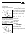
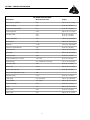
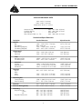
Manual Part No. 0C8221
SERVICE
MANUAL
GN724 V-T
TWIN
OHVI ENGINE
P. O. B o x 2 9 7 • W h i t e w a t e r, W I • 5 3 1 9 0
Phone: (262) 473-5514
Fax: (262) 472-6505
Printed in U.S.A
First Edition Issued - 051001
FOREWORD
This manual has been written and published by GENERAC® POWER
SYSTEMS, INC. to aid our dealers’ mechanics, company service personnel and general consumers when servicing the products described
herein.
It is assumed that these personnel are familiar with the servicing procedures for these products, or like or similar products, manufactured
and marketed by GENERAC® POWER SYSTEMS, INC. It is also assumed
that they have been trained in the recommended servicing procedures
for these products, which includes the use of mechanics hand tools
and any special tools that might be required.
Proper service and repair is important to the safe, economical and
reliable operation of the products described herein. The troubleshooting, testing, service and repair procedures recommended by
GENERAC® POWER SYSTEMS, INC. and described in this manual are
effective methods of performing such operations. Some of these operations or procedures may require the use of specialized equipment.
Such equipment should be used when and as recommended.
We could not possibly know of and advise the service trade of all
conceivable procedures or methods by which a service might be performed, nor of any possible hazards and/or results of each procedure
or method. We have not undertaken any such wide evaluation. Therefore, anyone who uses a procedure or method not recommended by
the manufacturer must first satisfy himself that neither his safety, nor
the product’s safety, will be endangered by the service or operating
procedure selected.
All information, illustrations and specifications contained in this
manual are based on the latest product information available at the
time of publication. However, GENERAC® POWER SYSTEMS, INC.
reserves the right to change, alter or otherwise improve the product
at any time without prior notice.
Some components or assemblies of the product described in this
manual may not be considered repairable. Disassembly, repair and
reassembly of such components may not be included in this manual.
The engines described herein may be used to power a wide variety
of products. Service and repair instructions relating to any such products are not covered in this manual. For information pertaining to use
of these engines with other products, refer to any owner’s or service
manuals pertaining to said products.
TABLE OF CONTENTS
4-CYCLE ENGINE THEORY .................................................................................................................................. 4
SECTION 1: GENERAL INFORMATION................................................................................................................ 5
SECTION 2: IGNITION ........................................................................................................................................ 10
SECTION 3: GOVERNOR .................................................................................................................................. 14
SECTION 4: CYLINDER HEAD AND VALVES .................................................................................................... 18
SECTION 5: ELECTRIC STARTERS ........................................................................................................................................ 24
SECTION 6: LUBRICATION SYSTEM ................................................................................................................ 30
SECTION 7: ENGINE DISASSEMBLY.................................................................................................................. 35
SECTION 8: CYLINDER AND CRANKCASE INSPECTION AND REPAIR ............................................................ 37
SECTION 9: CRANKSHAFT AND CAMSHAFT .................................................................................................. 41
SECTION 10: PISTON, RINGS AND CONNECTING ROD INSPECTION AND ASSEMBLY .................................. 42
SECTION 11: ENGINE ASSEMBLY .................................................................................................................... 45
A WORD ABOUT SPECIAL TOOLS
Many of the procedures depicted in this manual require the use of special tools. Some of
the tools required are available as Generac parts and are listed as such in this manual. Other
tools are listed only as Briggs & Stratton parts and must be acquired through a Briggs &
Stratton source of supply.
Portions of this manual have been reprinted from Briggs & Stratton P/N 273521-4/98
“Repair Manual For Intek™ V-twin Cylinder OHV Engines” with permission from Briggs &
Stratton.
All rights are reserved
ATTENTION!
Generac Power Systems does not approve or authorize the use of these engines on
All Terrain Vehicles (ATV”s), go-carts, motorbikes, aircraft products, personal watercraft, or vehicles intended for use in competitive events. Use of these engines in such
applications could result in property damage, serious injury (including paralysis), or
even death.
1
NOTES
2
If you don't understand any portion of this manual, contact
an authorized Generac service dealer.
Throughout this publication, DANGER, WARNING and CAUTION blocks are used to alert you to special instruction about
a particular operation that may be hazardous if performed incorrectly or carelessly. Observe them carefully.
These safety warnings cannot eliminate the hazards that
they indicate. Strict compliance with the special instructions
while performing the service plus "common sense" are major
measures to prevent accidents.
The following definitions apply to DANGER, WARNING, CAUTION and NOTE blocks found throughout the manual.
DANGER: After this heading you can read handling, installing, operating or servicing instructions
that, if not strictly complied with, will result in personal injury.
WARNING: After this heading you can read handling,
installing, operating or servicing instructions that,
if not strictly complied with, may result in personal
injury.
CAUTION: After this heading you can read instructions for handing, installing, operating or servicing
the engine that, if not strictly complied with, may
result in damage to equipment and/or property.
NOTE: After this heading you can read explanatory
statements that require special emphasis.
3
4-CYCLE ENGINE THEORY
If the engine is to run properly, four (4) events must occur
in the proper sequence and at the correct time. These events
are (a) intake, (b) compression, (c) ignition and power, and
(d) exhaust.
C IGNITION AND POWER
By the time the piston reaches TDC , combustion is already
in progress. The intake and exhaust valves remain closed as
the expanding gases of combustion force the piston downward.
A INTAKE
The piston is travelling from top dead center (TDC) to
bottom dead center (BDC). The cam has opened the intake
valve. The piston's downward movement in the cylinder creates a partial vacuum in the cylinder. Air at atmospheric
pressure is drawn into the cylinder through the carburetor
and is mixed with fuel in the carburetor. The fuel-air mixture flows through the open intake valve into the cylinder.
When the piston reaches BDC, the intake stroke is over.
D EXHAUST
The exhaust stroke begins when the piston has reached BDC
and has started its upward movement. The intake valve is
closed. The exhaust valve is open to let gases escape.
B COMPRESSION
As the piston reaches bottom dead center (BDC), both the
intake and exhaust valves are closed. The piston moves upward
toward TDC and the fuel-air mixture is compressed. Just before
the piston reaches TDC, ignition occurs.
4
SECTION 1: GENERAL INFORMATION
Purpose and Scope of Manual
This manual contains all information normally required to service or repair the Model GN-724 V-twin engine. Applicable
procedures are carefully explained and illustrated.
For exploded views and listings of engine parts, refer to the
Owner's Manual for the specific device on which the engine
is used.
When ordering parts, always include the model and serial
number of the engine. Be sure to insist on genuine Generac repair parts.
Systematic Check
If the engine will not start and the cause of malfunction is
not readily apparent, perform a systematic check in the following
order:
Fig. 6 - Running Check
Check Ignition
(Fouled Plug or Other Causes)
1. Ignition
2. Fuel
To check for a fouled spark plug or a non-functioning cylinder, attach the spark tester (Generac P/N 0C5969) between the
spark plug lead and each spark plug. Start and run engine at
top no load speed. Now ground one spark plug, Fig. 7. The
engine should continue to run on the other cylinder. Repeat
this test with the other cylinder. If the engine will not continue
to run when making this test, the cylinder that is NOT grounded
is not functioning and/or the spark plug is fouled. Install a new
spark plug before proceeding. If miss continues, problem may
be carburetion or compression. See Check Carburetion, Check
Compression. Also see Cylinder Balance Test.
3. Compression
This check-up, performed in a systematic manner, can usually be done in a matter of minutes. It is the quickest and surest
method of determining the cause of failure. The basic checkup procedure is the same for all engine models, while any
variation, by model, will be shown under the subject heading.
Check Ignition
If spark does not occur look for • Two closed diodes in ground wire harness
• Incorrect armature air gap
• Armature failure
• Shorted wire #18
Check Ignition
(Engine Running)
If engine runs but misses during operation, a quick check to
determine if ignition is or is not at fault can be made by
installing a spark tester (Generac P/N 0C5969) between the
spark plug lead and each spark plug, Fig. 6. A spark miss will
be readily apparent when the engine is running. If spark is good
but engine misses, check for a fouled spark plug.
Fig. 7 - Checking For Fouled Plugs
5
SECTION 1: GENERAL INFORMATION
Tools Required:
Check Fuel
The fuel pressure can be checked using a pressure tester kit
(Generac P/N 0C7977). This kit comes with an informative
“How To” video.
1. Two Ignition Testers (Generac P/N 0C5969)
2. Screwdriver with insulated handle
Attach an ignition tester between the spark plug lead and
each spark plug, Fig. 8.
Check Compression
It has been determined through testing, a simple and accurate indication of compression can be made as follows:
Remove both spark plugs and insert a compression gauge into
either cylinder (one cylinder at a time). Turn engine over with
engine starter until there is no further increase in pressure.
Record this reading. Repeat procedure on other cylinder and
record that reading. The difference between both cylinders
should not exceed 25%. More than 25% indicates loss of compression in the cylinder with lower pressure. See example.
EXAMPLE:
Eng. #1
Eng. #2
Fig. 8
Cyl. #1
65 PSI
75 PSI
Cyl. #2
60 PSI
55 PSI
Diff.
5 PSI
20 PSI
% Diff.
7.6%
26.7%
If compression is poor, look for:
Start and run engine running at top no load speed and note
spark at ignition testers. If the spark is equal at both ignition
testers, the problem is not ignition related. A spark miss will
be readily apparent. Now note RPM of engine. Ground out one
cylinder with screwdriver by contacting alligator clip on ignition tester and a good ground on engine, Fig. 9. Note RPM
loss. Then ground out the other spark plug and note the RPM
loss. If the difference between the two cylinders does not
exceed 75 RPM, the amount of work the two cylinders are doing
should be considered equal.
• Loose cylinder head bolts
• Blown head gasket
• Burned valves, valve seats and/or loose valve seats
• Insufficient valve clearance
• Warped cylinder head
• Warped valve stems
• Worn bore and/or rings
• Broken connecting rods
Cylinder Leakdown Test
A cylinder leakdown tester may be used to test the sealing
capability of the compression components of each cylinder and
quickly identify the problem component.
Cylinder Balance Test
If the engine is hard starting, runs rough, misses or lacks
power, perform a cylinder balance test to determine whether
both cylinders are operating to their full potential.
Fig. 9 — Cylinder Balance Test
6
SECTION 1: GENERAL INFORMATION
The cylinder balance test will also detect a cylinder that is not
functioning. When grounding out one cylinder there will be
no RPM loss. When the other cylinder is grounded out the
engine will stop.
Things Which Affect Both Cylinders
1. Carburetion
2. Crankcase vacuum
3. Ignition timing
NOTE: A twin cylinder engine will run well on one cylinder as long as the power required for the application does
not exceed the power produced by the one cylinder.
a. A partially sheared flywheel key will effect ignition timing
and engine performance.
If the RPM loss is greater than 75 RPM this indicates that the
cylinder with the least RPM loss is the weakest of the two cylinders. Look to that cylinder for a problem.
Equipment Affecting Engine Operation
Frequently, what appears to be a problem with engine operation, such as hard starting, vibration, etc., may be the fault
of the equipment powered rather than the engine itself. Listed
are the most common effects of equipment problems, and what
to look for as the most common cause.
Example.
Engine RPM - Both Cylinders = 3400 RPM
Engine RPM - #1 Cylinder Grounded = 3300 RPM
Engine RPM - #2 Cylinder Grounded = 3100 RPM
Hard Starting, or Will Not Start
1. Loose belt - a loose belt like a loose blade can cause a backlash effect, which will counteract engine cranking effort.
Conclusion: #1 cylinder is weakest of the two cylinders.
Things Which Affect One Cylinder
2. Starting under load - see if the unit is disengaged when engine
is started; or if engaged, should not have a heavy starting
load.
1. Spark plug
a. A fouled spark plug may indicate that carburetor is out
of adjustment.
2. Leak in spark plug wire
3. Head gasket
4. Intake manifold
a. A leak at either end of the intake manifold will only affect
one cylinder, not both.
5. Valves
6. Rings
7. Piston
8. Cylinder
7
SECTION 1: GENERAL INFORMATION
FASTENER SPECIFICATIONS
Description
Wrench/Socket Size
Torque
Back Plate (to cylinder)
3/8"
100 in. Ibs. (11.2 Nm)
Blower Housing
3/8"
80 in. Ibs. (9.0 Nm)
Carburetor (to manifold)
E-5
65 in. Ibs. (7.4 Nm)
Connecting Rod
5/16"
100 in. Ibs. (11.2 Nm)
Cylinder Shield
3/8"
5/16"
80 in. Ibs. (9.0 Nm)
45 in. Ibs. (5.0 Nm)
Exhaust Manifold
1/2"
140 in. Ibs. (16.0 Nm)
Fan Retainer
1/2"
140 in. Ibs. (16.0 Nm)
Flywheel
1-1/4"
150 ft. Ibs. (203.0 Nm)
Governor Control Bracket
3/8"
80 in. Ibs. (9.0 Nm)
Governor Nut
7/16"
130 in. Ibs. (14.6 Nm)
Head Bolts
1/2"
220 in. Ibs. (25.0 Nm)
Intake Air Horn
7/16"
45 in. Ibs. (5.0 Nm)
Intake Manifold (to cyl. head)
3/8"(T-30)
80 in. lbs. (9.0 Nm)
Oil Drain Plug
3/8" Square Drive (internal)
125 in. Ibs. (14.0 Nm)
Oil Pump Cover
T-30
50 in. Ibs. (5.6 Nm)
Rocker Arm
8 mm
100 in. Ibs. (11.2 Nm)
Rocker Arm Lock Nut
13 mm
60 in. Ibs. (6.6 Nm)
Rocker Arm Adjustment Screw
T-40
Rotating Screen
5/16"
20 in. Ibs. (2.2 Nm)
Spark Plugs
5/8" mm Deep
180 in. Ibs. (20.0 Nm)
Starter Motor
1/2" (T-40)
140 in. Ibs. (15.8 Nm)
Starter Thru Bolts
5/16"
50 in. Ibs. (5.6 Nm)
Sump
1/2"
200 in. Ibs. (22.6 Nm)
Valley Cover
5/16"
45 in. Ibs. (5.0 Nm)
Valve Cover
3/8"
100 in. Ibs. (11.2 Nm)
8
SECTION 1: GENERAL INFORMATION
SPECIFICATIONS MODEL GN724
Bore: 2.970" (75.44 mm)
Stroke: 2.890" (73.40 mm)
Displacement: 40.0 cu. in. (656 cc)
Armature Air Gap . . . . . . . . . . . . . . . . . . . . . ..008" - .012" (0.20 - 0.30 mm)
Crankshaft End Play . . . . . . . . . . . . . . . . . . . ..002" - .030" (0.05 - 0.76 mm)
Spark Plug Gap . . . . . . . . . . . . . . . . . . . . . . . ..030" (0.76 mm)
Valve Clearance (Cold) - Int. - Exh. . . . . . . . . . ..004" - .006" (0.10 - 0.15 mm)
Standard and Reject Dimensions
Description
Standard Dimension
Reject Dimension
Cylinder
Bore
Out of round:
Main Bearing (Magneto)
Cam Bearing (Magneto)
2.969" - 2.970" (75.41 - 75.44 mm)
.0015" (0.04 mm)
1.379" - 1.3805" (35.02 - 35.06 mm)
.6255" - .626" (15.88 - 15.90 mm)
2.973" (75.51 mm)
1.383" (35.12 mm)
.6275" (15.93 mm)
Cylinder Head
Valve Guide
Valve Stem
.2374" - .2383" (6.03 - 6.05 mm)
.2345" - .235" (5.97 - 5.98 mm)
.240" (6.09 mm)
.233" (5.92 mm)
Sump
Main Bearing (PTO)
Cam Bearing (PTO)
1.6268" - 1.6275" (41.32 - 41.34 mm)
.6255" - .626" (15.88 - 15.90 mm)
1.629" (41.37 mm)
.6275" (15.93 mm)
Crankshaft
Crankpin
Magneto Journal
PTO Journal
1.4982" -1.499" (38.05 - 38.07 mm)
1.3776" -1.3784" (34.99 - 35.01 mm)
1.6241" -1.6249" (41.25 - 41.27 mm)
1.4965" (38.01 mm)
1.376" (34.95 mm)
1.623" (41.22 mm)
Cam Shaft
Journals
Lobes
Intake
Exhaust
.624" - .625" (15.85 - 15.87 mm)
.623" (15.82 mm)
1.228" - 1.231" (31.19 - 31.26 mm)
1.226" - 1.229" (31.14 - 31.21 mm)
1.225" (31.15 mm)
1.223" (31.06 mm)
Connecting Rod
Crankpin Bearing
Piston Pin Bearing
1.500" -1.5006" (38.10 - 38.11 mm)
6727" - .673" (17.08 -17.09 mm)
1.5015" (38.13 mm)
.6745" (17.13 mm)
Piston Pin
.6721" - .6726" (17.07 - 17.08 mm)
.6718" (17.06 mm)
Piston Pin Bearing (Piston)
.673" - .6735" (17.09 -17.10 mm)
.6745" (17.13 mm)
Piston Ring
Ring End Gap -Top
Center
Oil
Ring Side Clearance (All)
.005" - .013" (0.13 - 0.33 mm)
.014" - .022" (0.35 - 0.56 mm)
.005" - .017" (0.13 - 0.43 mm)
.002" - .003" (0.05 - 0.07 mm)
.030" (0.76 mm)
.030" (0.76 mm)
.030" (0.76 mm)
.005" (0.12 mm)
9
SECTION 2: IGNITION
SECTION CONTENTS
REMOVING ARMATURES:
PAGE
SPECIFICATIONS ............................................................. 10
GENERAL INFORMATION ................................................ 10
ARMATURES
1. Remove spark plug leads and spark plugs.
2. Remove rotating screen and blower housing.
3. Remove armature screws and lift off armature(s), Fig. 1.
Testing ...................................................................... 10
a. Disconnect stop switch wires at armatures.
Remove Armatures .................................................... 10
Note:The flywheel does not need to be removed to service ignition except to check the flywheel key.
Install Armatures . ...................................................... 10
Adjust Armature Air Gap ............................................ 11
FLYWHEEL
Remove Flywheel . ...................................................... 11
Inspect Flywheel Key and Keyways .............................. 11
Install Flywheel ........................................................... 11
ENGINE WIRING HARNESS ............................................ 12
Testing Ground Wires.................................................. 12
Engine Wiring Harness Diagram ................................ 13
Diode Failure Diagnosis .............................................. 13
SPECIFICATIONS FOR GN724 OHVI V-TWIN ENGINE
MODEL SERIES ..........................................................GN724
ARMATURE AIR GAP.....................................008" TO .012"
(.20 TO .30 MM)
FLYWHEEL HOLDER
BRIGGS & STRATTON PART NO. ................................19321
FLYWHEEL PULLER
BRIGGS & STRATTON PART NO. ................................19203
FLYWHEEL NUT TORQUE
FT. LBS. ..........................................................................150
FLYWHEEL NUT TORQUE
NM ............................................................................203.0
Fig. 1 - Removing Armature
INSTALL ARMATURES:
1. Turn flywheel so magnet is away from armature.
2. Install ground wire onto tab terminal on armature.
Note: Make sure wires are routed over armature mounting posts and away from flywheel.
See Section 1 For Spark Plug Maintenance And Specifications
3. Assemble armature to engine, Fig. 2.
a. Mounting holes in armature are slotted. Push armature
away from flywheel as far as possible and tighten one screw
to hold armature in place.
GENERAL INFORMATION
Generac GN724 OHVI V-Twin engines use a magneto ignition: an ignition armature with a self-contained transistor
module (no moving parts). Two magneto ignition armatures
are used, with a flywheel containing a permanent magnet.
4. Repeat for second armature.
NOTE: The magneto ignition system requires a minimum
of 350 RPM to produce spark.
ARMATURES
ARMATURE TESTING:
The condition of the ignition armatures can accurately diagnosed using an ignition tester, (Generac P/N 0C5969) as
described in "Troubleshooting" in Section 1.
Fig. 2 - Installing Armature
10
SECTION 2: IGNITION
ADJUST ARMATURE AIR GAP:
4. Reinstall flywheel nut. Turn nut down flush with top of
threads.
1. Rotate flywheel until magnet is under armature
laminations.
5. Install flywheel puller.
2. Place thickness gauge, .008"-.012" (0.20-.30 mm)
6. Tighten puller screws equally until flywheel loosens, Fig. 5.
between magnet and armature laminations, Fig. 3.
DO NOT strike flywheel with a hard object or a metal
tool as this may cause flywheel to shatter in operation. Always use approved flywheel removal tools.
3. Loosen mounting screw so magnet will pull armature
down against thickness gauge.
a. Torque screws to 25 in. Ibs. (2.8 Nm).
4. Rotate flywheel to remove thickness gauge.
5. Repeat for second armature.
Note:Route armature ground wire between breather
tube and air horn.
Fig. 5 - Removing Flywheel
Inspect Flywheel Key, Keyways, Flywheel and
Crankshaft
Check flywheel key for damage. Check flywheel for cracks,
broken fins or keyway damage. Also check crankshaft keyways
and taper for damage, Fig. 6. Replace crankshaft, if damaged.
Fig. 3 - Adjusting Air Gap
FLYWHEEL
REMOVE FLYWHEEL:
1. Remove flywheel nut and washer.
2. Remove fan retainer and fan.
Fig. 6 - Check Flywheel And Crankshaft
Install Flywheel
Note: CLEAN flywheel and crankshaft taper removing all
oil, dirt or grease.
1. Assemble flywheel to crankshaft and align keyways.
Fig. 4 - Removing Flywheel Nut
2. Insert flywheel key into crankshaft.
11
SECTION 2: IGNITION
3. Assemble fan and retainer to flywheel, Fig. 7.
a. Torque screws to 140 in. Ibs. (16.0 Nm).
Fig. 9 - Engine Wiring Harness
Testing Ground Wires
Fig. 7 - Installing Flywheel And Fan
Use Digital Multimeter to test the ground wires, Fig. 10.
4. Install washer and flywheel nut.
The following test will be made with the meter in the Diode Test
position.
5. Assemble flywheel to retainer, Fig. 8.
a. Torque flywheel nut to 150 ft. Ibs. (203.0 Nm).
Fig. 10 - Digital Multimeter
Fig. 8-Torquing Flywheel Nut
In the Diode Test position, the meter will display the forward
voltage drop across the diode(s). If the voltage drop is less than
0.7 volts, the meter will "Beep" once as well as display the voltage drop. A continuous tone indicates continuity (shorted
diode) An incomplete circuit (open diode) will be displayed as
"OL."
ENGINE WIRING HARNESS
The engine wiring harness consists of a ground wire with a
diode for each armature and a separate wire for the carburetor solenoid, Fig. 9. The engine wiring harness is connected to
the wiring harness provided by the equipment manufacturer.
A raised rib on the polarized connector indicates the ground
side.
1. Insert RED test lead into
receptacle in meter.
2. Insert BLACK test lead into the “COM” receptacle in meter.
3. Rotate selector to
See engine wiring harness diagram, page 12.
(Diode Test) position.
4. Insert RED test lead clip into connector "A" (black wire), Fig.
11. Leave attached for remainder of test.
12
SECTION 2: IGNITION
5. Touch BLACK test lead probe to terminal "B."
a. If meter "Beeps" once, diode is OK.
b. If meter makes a continuous tone, diode is defective
(shorted). Replace ground harness.
c. If meter displays "OL," diode is defective (open). Replace
ground harness.
6. Now repeat test for terminal "C." Results must be the same.
See Diode Failure Diagnosis on page 5.
Fig. 11 - Testing Ground Wire
Engine Wiring Harness
DIODE FAILURE DIAGNOSIS
SWITCH ON
TURNED OFF
CAUSE
Engine Runs
On 1 Cylinder
Shuts Off OK
1 Closed Diode
Engine Runs
(Both Cylinders)
Only One Cylinder
Shuts Off
1 Open Diode
Won't Run
(No Spark)
Engine Runs
(Both Cylinders)
2 Closed Diodes
Engine Won't Shut Off
13
2 Open Diodes
SECTION 3: GOVERNOR CONTROLS AND GOVERNOR
SECTION CONTENTS
GOVERNOR
Disassemble ................................................................ 14
Check Governor Gear And Shaft ................................ 15
Install Governor Shaft Bushing .................................... 15
Reassemble. ................................................................ 16
ADJUST GOVERNOR........................................................ 17
GOVERNOR
DISASSEMBLE:
Drain oil and remove engine from equipment. Remove spark
plugs. Remove valve covers, depress springs and remove push
rods. Mark push rods so that they may be reassembled in their
original position. If push rods are mixed, it may be necessary
to readjust valve clearances.
Fig. 7 - Remove Oil Pump
3. Remove sump and discard gasket, Fig. 8.
a. Remove governor gear and thrust washer
Note: Intake push rods are aluminum.
1. Loosen governor lever nut.
a. Remove governor lever from shaft, Fig. 6.
Fig. 8 - Remove Sump
4. Remove governor shaft from sump, Fig. 9.
a. Remove lower E-ring.
Fig. 6 - Remove Governor Lever
b. Rotate governor paddle clockwise and slide governor
shaft out of bushing.
2. Remove oil pump. Fig. 7.
c. Remove and discard oil seal.
a. Remove oil pump cover.
b. Remove inner rotor.
c. Remove outer rotor.
d. Remove drive shaft.
Fig. 9 - Remove Governor Shaft
14
SECTION 3: GOVERNOR CONTROLS AND GOVERNOR
5. The following tools are required to remove the governor shaft
bushing, Fig. 10.
a. 3/8" drive 5/8" socket.
b. 1/4" flat washer.
c. 1/4 - 20 screw and nut.
d. Flat washer.
Fig. 12 - Check Governor Gear And Shaft
Install Governor Shaft Bushing
Lubricate new bushing and governor shaft with engine oil.
1. Assemble governor shaft to sump to act as a pilot for bushing.
Fig. 10 - Bushing Removal Tools
Do not install lower E-ring.
6. Assemble tools as shown.
2. Using Briggs & Stratton Tool P/N 19129, press in bushing until
it bottoms, Fig. 13.
a. Tighten nut until bushing is removed, Fig. 11.
3. Install lower E-ring.
a. Install new oil seal.
Governor shaft must rotate freely.
Fig. 11 - Remove Governor Shaft Bushing
Check Governor Gear And Shaft
SHAFT:
Fig. 13 - Install Governor Shaft Bushing
1. Check governor gear for burrs or nicks, Fig. 12.
2. Check flyweights for damage or wear.
3. Check governor cup and thrust washer for damage or wear.
4. Check governor gear shaft and bearings for damage or
wear.
Replace as required.
15
SECTION 3: GOVERNOR CONTROLS AND GOVERNOR
Reassemble
1. Lubricate thrust washer, governor gear and governor cup with
engine oil and assemble to shaft, Fig. 14.
Fig. 16 - Install Oil Pump
4. Reassemble governor lever to governor shaft, Fig. 17. DO
NOT tighten nut at this time.
Fig. 14 - Install Governor Gear
2. Install sump with new gasket, Fig. 15. a. Torque screws in
sequence shown to 200 in. Ibs. (22.6 Nm).
Fig. 17 - Install Governor Lever
5. Install push rods in their original positions.
a. Compress valve springs and insert push rods into recess
in rocker arm adjustment screws, Fig. 18.
Fig. 15 - Install Sump
Note: Intake push rods are aluminum.
3. Lubricate oil pump components with engine oil and assemble to sump, Fig. 16. Make sure drive shaft is engaged in
camshaft.
a. Install drive shaft.
b. Install inner rotor.
c. Install outer rotor.
d. Install oil pump cover with new O-ring.
e. Torque screws to 50 in. Ibs. (5.6 Nm).
Fig. 18 - Install Push Rods
16
SECTION 3: GOVERNOR CONTROLS AND GOVERNOR
6. Install valve covers with new gaskets, Fig. 19.
3. Start the engine; let it stabilize and warm up at no-load.
a. Torque screws to 100 in. Ibs. (11.2 Nm).
4. Turn the speed adjust nut to obtain a frequency reading of
62 Hertz.
5. When frequency is correct at no-load, check the AC voltage
reading. If voltage is incorrect, the voltage regulator may
require adjustment.
ENGINE SPEED
ADJUSTMENT NUT
Fig. 19 - Install Valve Covers
GOVERNOR
SHAFT
ADJUST GOVERNOR
1. Loosen the governor clamp bolt (Figure 3.2).
GOVERNOR CLAMP BOLT
BEND TAB
GOVERNOR SPRING
2. Push the spring end of the governor lever clockwise to the
wide open throttle position of the lever.
• Hold the governor lever at wide open throttle and, with a
screwdriver, rotate the governor shaft fully clockwise.
Fig. 20 - Engine Governor Adjustment
• Before tightening, verify that the governor lever is pushed
all the way onto the governor shaft.
NOTE: If the engine continues to run fast, use a pair of
pliers, or tang bender (Briggs P/N 19229 or 19352) to
bend the bend tang clockwise to release tension on the
lower governor spring.
• While holding the governor shaft fully clockwise and the governor lever at wide open throttle, tighten the governor clamp
bolt to 70 inch-pounds (8 N-m).
17
SECTION 4: CYLINDER HEAD AND VALVES
SECTION CONTENTS
REMOVE CYLINDER HEADS
PAGE
REMOVE CYLINDER HEAD .............................................. 18
DISASSEMBLE CYLINDER HEAD ...................................... 19
INSPECT AND REPAIR ...................................................... 20
Cylinder Head ............................................................ 20
Valve Guides .............................................................. 20
Valves ........................................................................ 20
ASSEMBLE CYLINDER HEAD............................................ 21
INSTALL CYLINDER HEAD ................................................ 22
ADJUST VALVES .............................................................. 23
ADJUST GOVERNOR........................................................ 23
Fig. 1 - Remove Cylinder Head
Over Head Valve Train
18
SECTION 4: CYLINDER HEAD AND VALVES
Fig. 9 - Cylinder Head Components
1. Remove valves, Fig. 10.
2. Remove and discard intake valve stem seals, Fig. 11.
Note: Place a shop rag or short section of rubber fuel line
under valves inside combustion chamber to hold
valve in place while compressing spring.
Thread rocker arm support screw into cylinder head a few
turns and compress spring with valve spring compressor, (Briggs
& Stratton P/N 19347). Remove the following:
a. Valve spring retainer locks
b. Valve spring retainer
c. Valve spring
d. IN and EX valve
Fig. 11 - Remove Valve Stem Seal
Fig. 10 - Remove Valves
19
SECTION 4: CYLINDER HEAD AND VALVES
INSPECT AND REPAIR
3. Valve seats may be reconditioned using valve seat cutter tool
(Briggs & Stratton P/N 19237 and P/N19343).
1. Check cylinder head, Fig. 12. Be sure all gasket material is
removed from surfaces before checking. Use a gasket scraper
if necessary.
b. Use a surface plate or straightedge and check cylinder head
mounting surface for distortion.
If valve seat is wider than dimension shown in Fig. 14, a narrowing cutter should be used to ensure that contact area of
valve seat is centered on face of valve. a. Use a 60° cutter to
narrow seat from bottom and a 15° cutter to narrow seat from
top, Fig. 18.
If mounting surfaces are distorted more than .004" (0.1
mm), the cylinder head must be replaced.
Note: If valve seat is loose or cracked, replace cylinder
head.
a. Inspect cylinder head for cracks or damage.
It is not recommended that cylinder head mounting surfaces be resurfaced.
Fig. 14 - Valve Seat Dimensions
4. Valve faces may be resurfaced to 45°. See Fig. 15 for dimensions for valves. Lap valves and seats with valve lapping tool,
(Briggs & Stratton P/N 19258) and valve lapping compound,
(Briggs & Stratton P/N 94150).
Fig. 12 - Check Cylinder Head For Distortion
2. Check valve guide bushings for wear using reject gauge,
(Briggs & Stratton P/N 19381), Fig. 13.
If valve guides are worn, the cylinder head must be replaced.
Fig. 15 - Valve Dimensions
Fig. 13 - Check Valve Guide Bushing
20
SECTION 4: CYLINDER HEAD AND VALVES
5. Measure valve stem diameter at specified distance from end
of valve, as shown in Fig. 16.
6. Check valve springs for free length, Fig. 17. Replace if free
length is less than 1.320" (33.5 mm).
Replace if less than .233" (5.92 mm).
Fig. 17 - Check Valve Springs
Fig. 16 - Measure Valve Stem Diameter
Fig. 18 - Cylinder Head Components
21
SECTION 4: CYLINDER HEAD AND VALVES
1. Use valve guide driver, (Briggs & Stratton P/N 19416) and
install new intake valve stem seal.
Fig. 21 - Install Valve Springs
4. Assemble rocker arms and supports to cylinder head, Fig. 22.
Apply Loctite® 242 or similar sealant to threads.
a. Oil inner surface and lip of valve stem seal.
b. Press seal on to valve guide bushing until it bottoms, Fig. 19.
a. Torque screws to 100 in. Ibs. (11.2 Nm).
Fig. 19 - Install Valve Stem Seals
Fig. 22 - Install Rocker Arms
2. Install valves. Note: Lightly coat valve stems with Valve Guide
Lubricant (Briggs & Stratton P/N 93963) before installing
valves.
INSTALL CYLINDER HEAD
1. Place cylinder head gasket over alignment dowels on cylinder block, Fig. 23.
Fig. 20 - Install Valves
3. Install valve springs with valve spring compressor, Tool (Briggs
& Stratton P/N 19347), Fig. 21.
Fig. 23 - Install Cylinder Head Gasket
2. Install cylinder head assembly, Fig. 24.
a. Torque head bolts in sequence shown to 220 in. Ibs. (25.0
Nm).
3. Install push rods. Make sure push rods are inserted in recess
in tappets.
Note: Intake push rods are aluminum.
22
SECTION 4: CYLINDER HEAD AND VALVES
Fig. 24 - Install Cylinder Head Assembly
Fig. 26 - Adjust Valve Clearances
4. Compress valve springs and insert push rods into recess in
rocker arm adjustment screws, Fig. 25.
3. Install valve covers with new gaskets, Fig. 27.
a. Torque screws to 100 in. Ibs. (11.2 Nm)
Fig. 25 - Install Push Rods
Fig. 27 - Install Valve Covers
ADJUST VALVES
ADJUST GOVERNOR
1. Set No. 1 cylinder at TDC, compression stroke.
a.
WARNING: BEFORE STARTING or running engine,
static adjustment of the governor must be completed! Failure to make the static adjustments first
could result in engine overspeeding which may result
in engine damage, property damage or personal
injury.
Adjust valves and check, Fig. 26.
Valve Clearance (cold) IN and EX .005" (0.13 mm)
b. Torque jam nut and adjusting screw to 60 in. Ibs. (6.6 Nm).
2. Set No. 2 cylinder at TDC, compression stroke.
a. Repeat for No. 2 cylinder.
STATIC GOVERNOR ADJUSTMENT
1. Rotate governor control swivel counter-clockwise as far as
it will go (wide open throttle) and hold in this position.
2. Rotate governor shaft clockwise as far it will go.
a. Torque governor nut to 130 in. lbs. (14.6 Nm).
23
SECTION 5: ELECTRIC STARTER
SECTION CONTENTS
TROUBLESHOOTING
PAGE
GENERAL INFORMATION ................................................ 24
TROUBLESHOOTING........................................................ 24
TEST EQUIPMENT ............................................................ 25
TEST STARTER MOTOR .................................................... 26
NOTE: If a starting problem is encountered, the engine
itself should be thoroughly checked to eliminate it as the
cause of starting difficulty. It is a good practice to check
the engine for freedom of rotation by removing the
spark plugs and turning the crankshaft over slowly by
hand, to be sure it rotates freely.
Remove Starter Motor ................................................ 26
Testing Starter Motor .................................................. 26
WARNING: DO NOT ROTATE ENGINE WITH ELECTRIC
STARTER WITH SPARK PLUGS REMOVED. ARCING AT
THE SPARK PLUG ENDS MAY IGNITE THE GASOLINE
VAPOR EXITING THE SPARK PLUG HOLE.
Starter Motor Specifications ........................................ 26
Conditions Affecting Starter Motor Performance ........ 26
STARTER DRIVE
Checking Starter Motor Drive...................................... 26
Disassemble Starter Motor Drive.................................. 27
ENGINE CRANKS SLOWLY:
Assemble Starter Motor Drive...................................... 27
DISASSEMBLE STARTER MOTOR...................................... 27
a. Additional load affecting performance (see note above).
b. Discharged battery.
Inspect Armature Commutator.................................... 28
c. Faulty electrical connection (battery circuit).
Inspect Brushes .......................................................... 28
ASSEMBLE STARTER ........................................................ 28
d. Discharged battery (see alternators).
Install Starter Motor .................................................... 29
e. Dirty or worn starter motor commutator, bearing, weak
magnets, etc.
GENERAL INFORMATION
The starter motor uses a gear type engagement method, similar to an automobile starter. When the starter motor is activated,
the pinion gear engages a ring gear attached to the engine
flywheel and cranks the engine.
f. Worn brushes or weak brush spring.
g. Wrong oil viscosity for temperature expected. h. Battery
leads too long or wire too small.
i. Battery too small.
The pinion gear and flywheel ring gear are replaceable.
ENGINE WILL NOT CRANK:
a. Faulty safety interlocks.
b. Discharged or defective battery.
c. Faulty electrical connections.
d. Faulty starter motor switch (open circuit).
e. Open circuit in starter motor.
f. Brushes sticking, etc.
g. Faulty solenoid.
STARTER MOTOR SPINS BUT DOES NOT CRANK ENGINE:
a. Sticking pinion gear due to dirt.
b. Damaged pinion or ring gear.
Fig. 1 - Starter Motor
c. Starter clutch slipping.
d. Battery faulty or damaged.
e. Incorrect rotation due to reversed motor polarity-all motors
rotate counterclockwise viewed from pinion gear.
STARTER MOTOR SPINS BUT WILL NOT STOP:
a. Defective starter switch.
24
SECTION 5: ELECTRIC STARTER
TEST EQUIPMENT
The following is a list of equipment recommended to test and
repair starter motors.
DIGITAL MULTIMETER:
The Digital Multimeter is available from your Briggs & Stratton source of supply. Order as Briggs & Stratton P/N 19357 or
19390. The meter may be used to read volts, ohms, amperes
and test diodes (rectifiers), Fig. 2.
The Digital Multimeter will withstand DC input of 10-20
Amps for up to 30 seconds. When checking current draw of
12 volt starter motors, the DC Shunt, Briggs & Stratton P/N
19359, is required.
Fig. 3 - DC Shunt - Briggs & Stratton P/N 19359
A tachometer is available from your Generac Power Systems
source of supply. Order as P/N 042223. The tachometer measures from 800 to 50,000 RPM, Fig. 4.
NOTE: The Digital Multimeter is equipped with two fuses
to prevent damage to the meter in the event that the
input limits are exceeded. If the meter displays a reading of 0.00 when testing DC output, check fuses in meter.
Refer to FLUKE Operators Manual for procedure for
checking fuses. Replacement fuse is available from your
Briggs & Stratton source of supply. Order (Briggs & Stratton P/N 19449.
Fig. 4 - Tachometer
TEST BRACKET
A starter motor test bracket may be made as shown in Fig.
5. A growler or armature tester is available from an Automobile Diagnostic service supplier.
Fig. 2 - Digital Multimeter
DC SHUNT:
Use with Digital Multimeter. The DC Shunt is required when
checking starter motor current draw on 12 volt starter motors.
Order as Briggs & Stratton P/N 19359, Fig. 3.
Fig. 5 - Test Bracket
25
SECTION 5: ELECTRIC STARTER
TEST STARTER MOTOR
REMOVE STARTER MOTOR:
It is recommended that the starter motor be removed from
the engine when testing starter motor performance. Remove
rotating screen and blower housing. Remove two starter motor
mounting screws. Assemble starter to test bracket and clamp
test bracket in vise, Fig. 6.
IMPORTANT: DO NOT clamp motor housing in a vise or
strike with a steel hammer. Starter motors contain two
ceramic magnets which can be broken or cracked if the
motor housing is hit, deformed or dented.
TESTING STARTER MOTOR:
A fully charged 12 volt battery is required.
1. The DC Shunt MUST be installed on the negative (-) battery
terminal as shown in Fig. 6.
2. Insert RED test lead into
receptacle in meter and connect to RED post terminal on shunt.
Fig. 6 - Testing Starter Motor
3. Insert BLACK test lead into “COM” receptacle in meter and
connect to BLACK post terminal on shunt.
4. Rotate selector to
CONDITIONS AFFECTING
STARTER MOTOR PERFORMANCE
position.
1. A binding or seizing condition in the starter motor
5. Activate the starter motor and note reading on meter and
tachometer (RPM).
bearings.
2. A shorted, open or grounded armature.
Note: Take reading after meter stabilizes (approximately
2 - 3 seconds).
a. Shorted, armature (wire insulation worn and wires touching one another). Will be indicated by low or no RPM.
6. A starter motor in good condition will be within specifications listed.
b. Open armature (wire broken) will be indicated by low or
no RPM and excessive current draw.
STARTER MOTOR SPECIFICATIONS:
c. Grounded armature (wire insulation worn and wire touching armature lamination or shaft). Will be indicated by
excessive current draw or no RPM.
MINIMUM RPM: ..........................................................6500
MAXIMUM AMPERES: ....................................................35
If 12 volt starter motor does not perform satisfactorily, see
Conditions Affecting Starter Motor Performance.
3. A defective starter motor switch.
4. Broken, damaged or weak magnets.
5. Starter drive dirty or binding.
STARTER DRIVE
CHECKING STARTER MOTOR DRIVE:
When the starter motor is activated, the pinion gear should
engage the flywheel ring gear and crank the engine. If the
starter motor drive does not react properly, inspect the helix
and pinion gear for freedom of operation, Fig. 7.
The pinion gear should be inspected for damaged teeth.
Pinion gear must move freely on helix. The parts may be
washed in a solvent such as Stanisol® or Varsol ®.
26
SECTION 5: ELECTRIC STARTER
ASSEMBLE STARTER DRIVE:
DISASSEMBLE STARTER MOTOR DRIVE:
1. Assemble clutch drive to starter shaft and rotate clutch until
it drops into place, Fig. 9.
WARNING: TO PREVENT EYE INJURY always wear
eye protection when removing C-ring.
2. Install pinion gear with beveled side of teeth up. Then install
return spring making sure spring is in recess of starter gear.
1. Place counterbore side of Briggs & Stratton P/N 19436 (Fig.
8) over retainer and align drive pins with open end of C-Ring.
3. Install spring washer with concave side up. Install retainer.
Important: If retainer has a notch as shown, DO NOT
align drive pins with notch. If necessary, rotate notch
away from open end of C-Ring.
2. Place palm of hand over tool and push down evenly
on tool to compress spring washer.
3. While applying pressure, turn knurled knob clockwise until
C-Ring pops off. Discard C-Ring.
4. Remove retainer, return spring, spring washer, pinion gear,
and starter clutch.
Fig. 9 - Assemble Starter Drive
4. Place C-Ring over chamfered end of shaft. Align one of the
slots of Briggs Tool P/N19435 with open end of C-Ring.
5. Press or drive C-Ring on until it snaps into groove in shaft, Fig. 10.
Fig. 7 - Starter Drive
Fig. 10 - Install C-Ring
DISASSEMBLE STARTER MOTOR:
See Fig. 11 for exploded view of starter motor.
To aid in reassembly, scribe a mark on drive end cap and starter
housing for alignment purposes.
1. Remove thru bolts.
2. Remove drive end cap assembly
Replace drive end cap if bushing is worn or damaged.
Fig. 8 - Removing C-Ring
27
SECTION 5: ELECTRIC STARTER
INSPECT ARMATURE COMMUTATOR:
The armature commutator may be cleaned with fine sandpaper. DO NOT use emery cloth. Commutator may be machined
to no less than 1.230" (31.24 mm), Fig. 13.
Slots between commutator bars should be cleaned with a hack
saw blade after cleaning or machining, Fig. 13. The slots can
also be cleaned using an aerosol carburetor cleaner or compressed air.
The armature should be checked for shorts with a growler.
Fig. 13 - Inspect Commutator
INSPECT BRUSHES:
Fig. 11 - Exploded View
The brushes should be checked for proper seating, weak brush
springs, dirt, oil or corrosion. Brush spring pressure should be
strong enough to ensure good brush contact with armature.
Check to be sure brushes are not sticking in their holders.
3. Hold the armature and commutator end cap against a work
surface while sliding housing off the armature, Fig. 12.
NOTE: This allows the brush retainer to remain assembled to commutator for inspection of brush to
commutator contact.
Minimum brush dimension is 1/4" (6 mm), Fig. 14.
Fig. 14 - Inspect Brushes
ASSEMBLE STARTER MOTOR:
Fig. 12 - Removing Armature
1. Assemble brushes in their proper holders.
4. Remove end cap and brush retainer with brushes. Replace
end cap if bushing is worn or damaged.
Note: Brush retainers may made using control wire (Briggs
& Stratton P/N 26634) as shown in Fig. 15.
28
SECTION 5: ELECTRIC STARTER
2. Assemble brush retainer to commutator and remove brush
retainers.
a. Assemble end cap to armature shaft.
Fig. 17 - Install Drive End Cap
5. Assemble spring washer and thrust washer to armature
shaft and install drive end cap, Fig. 17.
Fig. 15 - Assemble Brushes
a. Torque thru bolts to 50 in. Ibs. (5.6 Nm).
3. Hold armature and end cap against work surface.
6. Install starter drive.
4. Slide housing over armature, aligning notch in housing with
terminal on brush retainer, Fig. 16.
INSTALL STARTER MOTOR:
Install starter motor and torque screws to 140 in. Ibs.
(15.8 N m).
Fig. 16 - Install Starter Housing
29
SECTION 6: LUBRICATION SYSTEM
DESCRIPTION .................................................................. 30
PROTECTION SYSTEMS
DESCRIPTION
Generac GN724 OHVI V-Twins use a full pressure lubrication
system with an oil filter. The gear driven oil pump draws oil from
a screened oil pickup in the sump and pumps the oil through
the oil filter.
Low Oil Pressure Switch ..............................................30
High Temperature Switch ............................................30
CHECKING THE ENGINE OIL ............................................ 31
CHANGING THE ENGINE OIL .......................................... 31
CHANGING THE OIL FILTER ............................................ 31
CHECK PRESSURE SWITCH.............................................. 32
CHECK OIL PRESSURE .................................................... 32
CRANKCASE BREATHER .................................................. 32
The filtered oil flows through oil galleries in the sump and is
distributed to the main bearings, connecting rod bearings and
camshaft bearings. Engine oil pressure will vary with oil viscosity,
ambient air temperature differences, operating temperatures
and engine load. Follow the oil recommendation on page 1 of
this section. Oil Pressure - @ 70° F (21 ° C): 15 - 50 psi (1.0 3.5 Bar)
Check Breather .......................................................... 33
Install Breather ............................................................ 34
DISASSEMBLE OIL PUMP ................................................ 34
ASSEMBLE OIL PUMP ...................................................... 34
A pressure relief valve limits the maximum oil pressure in the
system.
PROTECTION SYSTEMS
LOW OIL PRESSURE SWITCH:
This switch (Figure 2.3) has normally closed contacts that are
held open by engine oil pressure during cranking and operating. Should oil pressure drop below the 8 psi range, switch
contacts close, and the engine shuts down. The unit should
not be restarted until oil is added, and the Auto/Off/Manual
switch must be turned to OFF and then back to AUTO.
HIGH TEMPERATURE SWITCH:
This switch’s (Figure 2) contacts close if the temperature
should exceed approximately 140º C (284º F), initiating an
engine shutdown. Your generator will automatically restart
and the LED will reset once the temperature has returned to
a safe operating level.
Fig 1
Use a high quality detergent oil classified "For Service
SE" or higher. Use no special additives with recommended oils.
Fig. 2
30
SECTION 6: LUBRICATION SYSTEM
CHECKING THE ENGINE OIL LEVEL
OIL CHANGE PROCEDURE:
The oil capacity of the GN724 OHVI engine is approximately
2 quarts. To check the engine oil level, proceed as follows:
To change the oil, proceed as follows:
1. Run the engine until it is thoroughly warmed up then shut
OFF the engine.
1. Start the generator by moving the Auto/ Off/Manual switch
to the MANUAL position. Allow it to run for a short while
and then shut it down by moving the switch to the OFF position.
2. Immediately after the engine shuts OFF, pull the oil drain hose
(Figure 3) free of its retaining clip. Remove the cap from the
hose and drain the oil into a suitable container.
2. Remove the dipstick and wipe it dry with a
clean cloth.
3. Install and tighten the dipstick cap; then, remove it again.
The oil level should be at the dipstick “Full” mark. If necessary, add oil to the “Full” mark only. DO NOT FILL ABOVE
THE “FULL” MARK.
Never operate the engine with the oil level below the
“Add” mark on the dipstick. Doing this could damage
the engine.
4. Install and tighten the dipstick.
5. Reset the Auto/Off/Manual switch to its original position.
3. After the oil has drained, replace the cap onto the end of
the oil drain hose. Retain the hose in the clip.
4. Refill with the proper recommended oil.
CHANGING THE OIL FILTER
Change the engine oil filter as follows:
1. With the oil drained, remove the old oil filter by turning it
counterclockwise.
CHANGING THE ENGINE OIL
ENGINE OIL RECOMMENDATIONS:
Use oil of American Petroleum Institute (API) Service Class SG,
SH or SJ. Select the viscosity based on the air temperature at
the time of operation. See the following chart:
Temperature
Above -7º C (20º F)
Oil Grade (Recommended)
SAE 10W-30 or SAE 30
Below -7º C (20º F)
SAE 5W-20 or 5W-30
All Seasons
SAE 5W-30 Synthetic*
2. Apply a light coating of clean engine oil to the gasket of the
new filter.
*Organic break-in oil is required before using synthetic oil.
Any attempt to crank or start the engine before it has
been properly serviced with the recommended oil may
result in an engine failure.
31
SECTION 6: LUBRICATION SYSTEM
3. Screw the new filter on by hand until its gasket lightly contacts the oil filter adapter. Then, tighten the filter an additional
3/4 to one turn (Figure 3.4).
Low oil pressure may be caused by the following reasons:
• Engine RPM Too Low
4. Refill with the proper recommended oil (see owner’s manual
for oil capacities).
• Low Oil Level
5. Start the engine and check for leaks.
• Missing Pressure Relief Plunger
• Wrong Viscosity or Diluted Oil
• Broken Pressure Relief Spring
• Worn Bearings
CHECK PRESSURE SWITCH
• Damaged Or Defective Oil Pump
Use a Digital multimeter. Set meter to test for continuity.
High oil pressure may be caused by the following reasons:
• Wrong Viscosity Oil
Remove pressure switch for testing. Connect one continuity
tester lead to the switch terminal and the other tester lead to
the metal body of the switch, Fig. 5. The tester should indicate continuity when no pressure is applied to the switch. The
switch should open (no continuity) when approximately 4.5 PSI
(0.3 Bar) is applied. Replace the switch if test results are not
to specification.
• Plugged Oil Galleries
• Stuck Pressure Relief Plunger
Fig. 6 - Checking Oil Pressure
CRANKCASE BREATHER
The crankcase breather is equipped with a reed valve to control and maintain a partial vacuum in the crankcase. The
breather is vented to the intake elbow. The breather chamber
contains a removable oil vapor collector. Oil vapor is condensed
on the collector material and drains back into the crankcase,
which minimizes the amount of oil vapor entering the breather.
Fig. 5 - Checking Pressure Switch
CHECK OIL PRESSURE
1. Oil level must be between the LOW and FULL mark on dipstick. If oil level is low, check for leaks and add to FULL
mark.
2. Remove pressure switch.
3. Install oil pressure gauge, Fig. 6.
4. Start and run engine for approximately 5 minutes. 5. Check
oil pressure at 3000 RPM.
5. Check oil pressure.
Oil Pressure @ 70° F (21 ° C): 15 ~ 50 psi (1.0 ~ 3.5 Bar)
Fig. 7 - Crankcase Breather
32
SECTION 6: LUBRICATION SYSTEM
CHECK BREATHER:
DISASSEMBLE OIL PUMP:
Remove rotating screen, blower housing and flywheel. See
Section 2.
Drain oil and remove oil filter. Remove engine from equipment. Remove spark plugs. The oil pump can be inspected or
replaced without removing the sump.
1. Disconnect breather tube from intake elbow, remove three
screws and breather. Discard gasket.
1. Remove the following parts, Fig. 10.
2. Check to see that reed valve is not deformed, Fig. 8.
a. Remove oil pump cover
b. Remove inner rotor.
c. Remove outer rotor.
d. Remove shaft.
e. Remove and discard O-ring
Fig. 8 - Checking Breather
Note: Reed valve must make a complete seal around
vent hole.
3. Remove oil vapor collector and retainer.
4. Check collector for deterioration and replace if necessary.
Fig. 10 - Remove Oil Pump
INSTALL BREATHER:
1. Install oil vapor collector and retainer.
2. Check rotors and shaft for any obvious wear and/or damage,
Fig. 11. Replace as necessary.
Note: Push oil vapor collector and retainer in until
it bottoms.
If pump housing is worn or damaged the sump must be
replaced.
2. Install breather with new gasket, Fig. 9.
a. Torque screws to 55 in. Ibs. (6.2 Nm).
b. Assemble breather tube to intake elbow.
Fig. 11 - Checking Oil Pump
ASSEMBLE OIL PUMP
1. Lubricate oil pump components with engine oil and assemble to sump, Fig. 12. Make sure drive shaft is engaged in
camshaft.
Fig. 9 - Install Breather
33
SECTION 6: LUBRICATION SYSTEM
a. Install drive shaft.
b. Install inner rotor.
c. Install outer rotor.
d. Install new O-ring.
e. Install oil pump cover.
2. Torque screws to 50 in. Ibs. (5.6 Nm). The oil pump is virtually trouble free and requires very little maintenance.
Fig. 12 - Assembling Oil Pump
34
SECTION 7: ENGINE DISASSEMBLY
ENGINE DISASSEMBLY
3. Remove sump and discard gasket, Fig. 3.
Drain oil, remove oil filter and remove engine from equipment. Remove spark plugs. Remove cylinder heads. See Section
5. Remove flywheel, disconnect stop switch wires at armatures
and remove armatures. See Section 2.
a. Remove governor gear and thrust washer.
1. Remove the following parts, Fig. 1.
a. Back plate
b. Air guide
c. Starter motor
d. Oil fill tube and dipstick
e. Stop switch wiring harness
f. Breather and oil vapor collector
g. Alternator
Fig. 3 - Remove Sump
4. Rotate crankshaft and camshaft until timing marks align and
remove camshaft, Fig. 4.
a. Remove tappets.
Fig. 1 - Remove Back Plate And Starter Motor
2. Remove oil pump. Fig. 2.
a. Oil pump cover
b. Inner rotor
c. Outer rotor
Fig. 4 - Align Timing Marks
d. Drive shaft
Note: Remove any carbon or ridge at the top of cylinder
bores to prevent breaking rings when removing piston
and connecting rod assemblies.
5. Remove No. 2 connecting rod cap and push connecting rod
and piston assembly out of cylinder.
a. Reassemble cap to rod to prevent interchanging.
6. Repeat for other cylinder.
7. Remove crankshaft.
CLEAN ALL SURFACES OF GASKET MATERIAL. REMOVE
OIL SEALS AND THOROUGHLY CLEAN COMPONENTS IN
SOLVENT. ORGANIZE COMPONENTS, KEEPING PARTS
WHICH ARE AN ASSEMBLY TOGETHER.
Fig. 2 - Remove Oil Pump
35
SECTION 7: ENGINE DISASSEMBLY
Fig. 5 - Remove Piston And Connecting Rod
Fig. 6 - Remove Crankshaft
36
SECTION 8: CYLINDER & CRANKCASE COVER INSPECTION & REPAIR
SECTION CONTENTS
NOTE: If cylinder bores are within specification and show
no signs of scoring or other damage, new piston rings
may be installed providing the cylinder bores are reconditioned using a rigid hone with finishing stones, to
restore the proper cross hatch angle in the cylinder bores. The
proper cylinder cross hatch ensures proper lubrication and
piston ring break in.
..................................................................................PAGE
CYLINDER ...................................................................... 37
Check Cylinder............................................................ 37
Resizing ...................................................................... 37
Cylinder Finish ............................................................ 38
Cleaning .................................................................... 38
BEARINGS ...................................................................... 39
Refer to Page 2, "Cylinder Finish" (Cross Hatch) for correct
procedure for installing cross hatch.
Check Mag Bearing .................................................... 39
Remove Mag Bearing .................................................. 39
Install Mag Bearing .................................................... 39
Check Camshaft Bearings .......................................... 39
Check PTO Bearings .................................................... 40
Install PTO Oil Seal ...................................................... 40
CHECK CYLINDER
Check cylinder for cracks, stripped threads or broken fins.
Check cylinder bores for damage or scoring.
1. Check cylinder head mounting surface for distortion with a
straight edge, Fig. 1.
If mounting surfaces are distorted more than .004" (0.1
mm), the cylinder must be replaced.
Fig. 2 - Check Cylinder Bore
RESIZING:
Always resize to exactly .010" (25 mm) or .020" (.51 mm)
or.030" (.76 mm) over standard bore size. If this is done accurately, the service oversize rings and pistons will fit perfectly
and proper clearances will be maintained.
Cylinders can be quickly resized with a good hone such as
Briggs Tool P/N19205. Contact your Briggs & Stratton source
of supply. Use the stones and lubrication recommended by the
hone manufacturers to produce the correct cylinder cross
hatch.
NOTE: Automatic transmission fluid is an acceptable
honing oil. Another acceptable honing oil can be made
by mixing 4 parts No. 30 weight oil with 1 part kerosene.
Fig. 1 - Checking Cylinder
2. Check cylinder bores for wear using telescoping gauge,
Briggs Tool P/N19404 and dial caliper, Briggs Tool P/N19199.
If a boring bar is used, a hone must be used after the boring
operation to produce the proper cylinder cross hatch.
Standard Bore Size: 2.969"-2.970" (75.41-75.43 mm)
a. Measure cylinder bore in 6 points at right angles as shown,
Fig. 3.
Honing is done with a variable speed 1 /2", portable drill and
a honing fixture. See page 5 for dimensions to make your own
honing fixture.
b. If cylinder bore is worn more than .003" (0.075 mm) or
more than .0015" (0.035 mm) out of round, it must be
resized.
Use three crankcase cover mounting screws and fasten cylinder to a honing fixture, Fig. 3.
Clamp honing fixture and cylinder securely in a vise at a convenient work height. Place hone drive shaft in chuck of portable
drill and tighten.
37
SECTION 8: CYLINDER & CRANKCASE COVER INSPECTION & REPAIR
Cut a wood block and place inside cylinder to prevent hone
from extending further than 3/4" to 1" (19 mm to 25 mm)
below cylinder bore.
travels full length of cylinder bore, and no more than 3/4" to
1" above cylinder bore, Fig. 3. Lubricate hone frequently to prevent build up on stones.
Place hone in middle of cylinder bore. Tighten adjusting
knob with finger until stones fit snugly against cylinder wall.
DO NOT FORCE. Connect drive shaft to hone. Be sure that cylinder and hone are centered and aligned with drive shaft and
drill spindle.
As cutting tension decreases, stop hone and tighten adjusting knob following hone manufacturer's recommendations.
Check cylinder bore frequently.
CYLINDER FINISH (CROSS HATCH):
The finishing stones are used after the cylinder bore has
been resized to within .0015" (.04 mm) of the desired size or
when reconditioning a cylinder bore. The as finishing stones
will produce the correct cross hatch necessary for proper lubrication. The correct cross hatch angle is approximately 45
degrees, Fig. 4.
It is recommended that the cylinder bores be reconditioned
to restore the cross hatch when new piston rings are to be
installed in a cylinder that is within specification. Be careful not
to hone oversize or it will be necessary to resize the cylinder.
NOTE: To produce the proper cross hatch finish use a drill
speed of approximately 200 RPM and 40-60 Hatch strokes
per minute. Lubricate hone liberally to prevent build up
on finishing stones.
Fig. 4 - Cylinder Cross
CLEANING:
IT IS MOST IMPORTANT THAT THE ENTIRE CYLINDER AND
CRANKCASE BE THOROUGHLY CLEANED AFTER HONING.
Fig. 3
First wash the cylinder and crankcase carefully in a solvent such as
kerosene or commercial solvent. Then thoroughly wash cylinder and
crankcase using a stiff brush with soap and hot water. Rinse thoroughly
with hot running water. Repeat washing and rinsing until all traces
of honing grit are gone.
Lubricate hone as recommended by hone manufacturer. The
recommended drill speed is 300 to 700 RPM MAXIMUM and
40-60 strokes per minute. Because cylinder bores normally
wear only in the area of ring travel, the cylinder bore will be
round above and below ring travel, Fig. 3. Start drill and, as
hone spins, move it up and down at the bottom of the cylinder bore. Gradually increase the length of the strokes until hone
38
SECTION 8: CYLINDER & CRANKCASE COVER INSPECTION & REPAIR
Honing grit is highly abrasive and will cause rapid wear to all
of the internal components of the engine unless it is completely
removed.
NOTE: When cylinder and crankcase have been thoroughly cleaned, use a clean white rag or napkin and
wipe the cylinder bore. If honing grit is present it will
appear as a gray residue on rag. If any honing grit is evident, re-wash and rinse entire cylinder and crankcase and
check again. When there is no trace of honing grit on rag,
the cylinder is properly cleaned. Then oil cylinder bore
to prevent rusting.
BEARINGS
Fig. 6 - Remove Mag Bearing
CHECK MAG BEARING:
Check DU magneto bearing for damage. Check for wear using
plug gauge Briggs Tool P/N19219, Fig. 5. Try gauge at several
locations. If plug gauge is not available see reject dimension
below.
INSTALL MAG BEARING:
Reject Dimension: 1.383" (35.12 mm)
2. Align oil hole in DU bearing with oil hole in cylinder.
1. Place cylinder on cylinder support, Briggs Tool P/N19227
with large opening facing bearing, Fig. 7.
3. Press in new bearing to correct depth with bushing driver,
Briggs Tool P/N19226.
Replace bearing if damaged or worn.
Fig. 7 - Install Mag Bearing
Fig. 5 - Check Mag Bearing
4. Stake bearing from both sides with 1/4" round punch to prevent bearing from turning, Fig. 8.
REMOVE MAG BEARING:
Insert bushing driver, Briggs Tool P/N19226 into bearing from
oil seal side. Place a reference mark on driver to indicate proper
depth of bushing when installing new bushing.
a. Install new oil seal with sealing lips facing in.
b. Use cylinder support, Briggs Tool P/N19227 and press oil
seal until flush with cylinder.
1. Place cylinder on cylinder support, Briggs Tool P/N19227
with large opening facing DU bearing, Fig. 6.
CHECK CAMSHAFT BEARINGS
2. Press out bearing with bushing driver, Briggs Tool P/N 19226.
Check camshaft bearings in cylinder and sump for damage
or wear.
Reject Dimension: .6275" (15.93 mm)
If bearings are damaged or worn the cylinder or crankcase
cover must be replaced.
39
SECTION 8: CYLINDER & CRANKCASE COVER INSPECTION & REPAIR
CHECK PTO BEARING
Check PTO bearing for damage or wear.
Reject Dimension: 1.629" (41.37 mm)
If PTO bearing is damaged or worn the sump must be
replaced.
Fig. 10 - Check PTO Bearing
INSTALL PTO OIL SEAL:
Always install new oil seals whenever engine is disassembled
for major servicing. When installing new PTO oil seal, use cylinder support, Briggs Tool P/N19227 and press oil seal slightly
below mounting surface. Always lubricate sealing lips with
engine oil to prevent damaging seal when installing crankshaft.
Fig. 8 - Stake Bearing
Fig. 9 - Check Cam Bearings
Fig. 11 - Install Oil Seal
40
SECTION 9: CRANKSHAFT & CAMSHAFT
SECTION CONTENTS
PAGE
CHECKING CRANKSHAFT .............................................. 41
CHECKING CAMSHAFT .................................................. 41
CHECKING CRANKSHAFT:
Inspect crankshaft threads and keyways for damage or wear.
If threads or keyways are damaged or worn, replace crankshaft.
Check journals for scoring. If journals are scored, replace crankshaft. Check journals for wear. See crankshaft reject sizes.
Crankshaft Reject Sizes
Model
Series
405770
PTO
Journal
Mag.
Journal
Crankpin
Journal
1.623"
(41.22 mm)
1.376"
(34.95 mm)
1.4965"
(38.01 mm)
Fig. 1 - Checking Crankshaft
Check oil galleries for blockage or obstructions. Check timing
gear for damaged teeth. Timing gear is replaceable. See illustrated parts list.
Crankshaft crankpin may re-ground for .020" undersize connecting rods, Fig. 2. See illustrated parts list for part number.
See crankshaft grinding dimensions.
Crankshaft Grinding Dimensions
Dim. A
Dim. R
Dim. T
1.4782/1.479"
(37.54/37.56 mm)
.170/.180"
(4.32/4.57 mm)
1.4435/1.4465
(36.66/36.74 mm)
Fig. 2 - Crankshaft Dimensions
Complete instructions are included with undersize connecting rods.
CHECKING CAM SHAFT:
Inspect gear teeth, lobes and journals for wear and nicks, Fig.
3. Check oil galleries for blockage or obstructions. Camshaft
journal and lobe reject sizes are shown below. Replace cam gear
if not to specification.
Camshaft Reject Size
Journals
(Mag & PTO)
Intake
Lobes
Exhaust
lobes
.623"
(15.82 mm)
1.225"
(31.15 mm)
1.223"
(31.06 mm)
Fig. 3 - Checking Camshaft
41
SECTION 10: PISTON, RINGS & CONNECTING ROD INSPECTION & ASSEMBLY
SECTION CONTENTS
2. Disassemble piston from connecting rod, Fig. 2.
PAGE
GENERAL INFORMATION ................................................ 42
DISASSEMBLE PISTON AND CONNECTING ROD .............. 42
CHECKING PISTON AND RINGS ...................................... 42
CHECKING PISTON PIN AND CONNECTING ROD ............ 43
ASSEMBLE PISTON AND CONNECTING ROD .................. 43
ASSEMBLE PISTON RINGS TO PISTON .............................. 44
a. Remove piston pin locks.
b. Piston pin is a slip fit in piston and connecting rod.
Keep pistons and connecting rods together as an assembly.
Do not mix.
GENERAL INFORMATION
It is recommended that new piston rings be installed whenever the engine is disassembled for major servicing or overhaul,
providing that cylinder bores are within specification.
Remove any carbon or ridge at the top of the cylinder bore.
This will prevent breaking the rings when removing the piston
and connecting rod from the engine. Remove the connecting
rod cap. Push the piston and connecting rod out through the
top of the cylinder.
Measure cylinder bores before checking pistons and rings.
See Section 10. If cylinder bores) require re-sizing it will not be
necessary to check pistons and rings since a new oversized
piston assembly will be used.
Fig. 2 - Remove Piston Pin Locks
CHECKING PISTON AND RINGS
If the cylinder bore is more than .08 mm (.003") oversize, or
.04 mm (.0015") out of round, it must be resized.
If the cylinder is not going to be resized and the piston shows
no signs of scoring, the piston should be checked.
DISASSEMBLE PISTON AND CONNECTING ROD
1. Check side clearance of ring grooves using NEW rings, Fig.
3. If a .005" (0.12 mm) feeler gauge can be inserted, the
ring groove is worn. The piston must be replaced.
1. Remove piston rings using ring expander, Briggs & Stratton
P/N 19340, Fig. 1.
a. Then remove coil expander.
Fig. 3 - Check Ring Grooves
Fig. 1 - Remove Rings
42
SECTION 10: PISTON, RINGS & CONNECTING ROD INSPECTION & ASSEMBLY
2. Check ring end gap, Fig. 4.
a. Clean carbon from end of rings and insert approximately
1" (25 mm) into cylinder.
Reject Dimension (all): .030" (0.76 mm)
3. Check piston pin bore, Fig. 5.
a. Replace if greater than .6745" (17.13 mm) or .0005"
(.01 mm) out of round.
Fig. 6 - Check Piston Pin
Connecting Rod Reject Size
Crankpin Bearing
Piston Pin Bearing
1.5015" (38.13 mm)
.6745" (17.13 mm)
Note: .020" undersize connecting rods are available for
use on a reground crankpin journal. See illustrated parts
list.
Fig. 4 - Checking Ring End Gap
Fig. 7 - Check Rod Bearings
ASSEMBLE PISTON AND CONNECTING ROD
Lubricate parts with engine oil and assemble #1 piston and
connecting rod, Fig. 8.
1. Arrow on piston must face flywheel side.
Fig. 5 - Check Piston Pin Bore
2. Number "1" on connecting rod must face PTO side (opposite arrow on piston).
CHECKING PISTON PIN AND CONNECTING ROD
a. Install piston pin locks with needle nose pliers.
1. Check piston pin, Fig. 6.
Lubricate parts with engine oil and assemble #2 piston and
connecting rod, Fig. 9.
a. Replace if less than .6718" (17.06 mm) or .0005" (.01 mm)
out of round.
2. Check connecting rod bearings.
1. Arrow on piston must face flywheel side.
Note: If crankpin bearing is scored or worn the connecting rod must be replaced.
2. Number "2" on connecting rod must face PTO side (opposite arrow on piston).
a. Install piston pin locks with needle nose pliers.
43
SECTION 10: PISTON, RINGS & CONNECTING ROD INSPECTION & ASSEMBLY
ASSEMBLE PISTON RINGS TO PISTON
1. Install piston rings using ring expander, Briggs Tool P/N19340,
Fig. 10.
a. Install oil ring coil expander making sure wire is inserted
fully into coil.
b. Install oil ring.
c. Install center compression ring then, top compression
ring.
Note: Top compression ring maybe installed with either
side up.
Fig. 8 - Assemble #1 Rod And Piston
Fig. 9 - Assemble #2 Rod And Piston
Fig. 10 - Piston Ring Installation
44
SECTION 11: ENGINE ASSEMBLY
SECTION CONTENTS
INSTALL CRANKSHAFT .................................................... 45
INSTALL PISTON AND CONNECTING ROD........................ 45
INSTALL CAM SHAFT ...................................................... 46
INSTALL SUMP ................................................................ 46
GENERAL ASSEMBLY ...................................................... 46
INSTALL FLYWHEEL.......................................................... 47
ADJUST ARMATURE AIR GAP .......................................... 48
INSTALL CYLINDER HEADS .............................................. 48
ADJUST VALVES .............................................................. 48
INSTALL CRANKSHAFT
Lubricate mag bearing and lips of oil seal with engine oil and
install crankshaft.
Fig. 2 - Compressing Rings
2. Lubricate cylinder bores and crankpin and rotate crankshaft
until it as at bottom of stroke.
3. Install #1 piston with arrow towards flywheel side, Fig. 3.
a. Push piston down by hand until connecting rod is seated
on crankpin.
Fig. 1 - Installing Crankshaft
INSTALL PISTON AND CONNECTING ROD
Note: Install #1 piston and connecting rod first.
1. Oil piston rings, piston skirt, and compress rings with Ring
Compressor, Briggs & Stratton P/N 19070, Fig. 2.
Fig. 3 - Installing Piston And Connecting Rod
a. Place piston and ring compressor upside down on bench
with projections on compressor facing up.
4. Assemble connecting rod cap to rod with match marks
aligned, Fig. 4.
b. Tighten ring compressor evenly until rings are fully compressed.
a. Torque screws to 100 in. Ibs. (11.2 Nm).
c. Then loosen ring compressor very slightly so that compressor can be rotated on piston skirt while holding
connecting rod, Fig. 2.
Fig. 4 - Torque Connecting Rods
45
SECTION 11: ENGINE ASSEMBLY
d. Install oil pump cover with new O-ring.
5. Rotate crankshaft two revolutions to check for binding. Rod
should also be free to move sideways on crankpin.
e. Torque screws to 50 in. Ibs. (5.6 Nm).
Repeat for #2 cylinder.
Note: The number 1 on #1 connecting rod and the number
2 on #2 connecting rod must be facing PTO side.
Important: Failure to use a torque wrench can result in
loose connecting rod screws causing breakage or tight
connecting rod screws causing scoring.
INSTALL CAMSHAFT
Lubricate tappets, cam shaft journals and lobes with engine
oil. Assemble timing gear to crankshaft.
1. Install tappets.
2. Align timing marks on cam shaft and crankshaft gear and
install cam shaft, Fig. 5.
Fig. 6 - Installing Crankcase Cover
3. Lubricate thrust washer, governor gear and governor cup and
assemble to shaft.
Fig. 7 - Assemble Oil Pump
Fig. 5 - Installing Camshaft
GENERAL ASSEMBLY
1. Install armatures and ground wire assembly.
INSTALL SUMP
Note: Push armatures away from crankshaft as far as
they will go and temporarily tighten screws.
Lubricate PTO and cam gear bearing.
1. `Install sump with new gasket.
2. Install air guide.
a. Torque screws in sequence shown to 200
a. Torque screws to 45 in. Ibs. (5.0 Nm).
in. Ibs. (22.6 Nm), Fig. 6.
3. Install alternator.
2. Check crankshaft end play.
a. Torque screws to 20 in. Ibs. (2.2 Nm).
Specification: .002"-.030" (0.020-0.30 mm)
4. Assemble oil fill tube to cylinder and crankcase cover, Fig. 9.
3. Lubricate oil pump components with engine oil and assemble to sump, Fig. 7. Make sure drive shaft is engaged in
camshaft.
a. Route alternator wires between oil fill tube mounting
boss on cylinder and oil fill tube bracket.
b. Route wiring harness between oil fill tube and cylinder.
a. Install drive shaft.
b. Install inner rotor.
c. Install outer rotor.
46
SECTION 11: ENGINE ASSEMBLY
6. Install starter motor.
a. Torque screws to 140 in. Ibs. (15.8 Nm).
7. Install oil vapor collector and retainer.
8. Install breather.
a. Torque screws to 55 in. Ibs. (6.2 Nm).
Fig. 8 - Install Armatures
Fig. 11 - Install Starter Motor
INSTALL FLYWHEEL
Note: Clean flywheel and crankshaft taper removing all
oil, dirt or grease.
1. Assemble flywheel to crankshaft and align keyways.
2. Insert flywheel key into crankshaft.
Fig. 9 - Route Wires
3. Assemble fan and retainer to flywheel, Fig. 12.
5. Install back plate.
a. Torque screws to 140 in. Ibs. (16.0 Nm).
a. Torque screws to 100 in. Ibs. (11.2 Nm).
4. Install washer and flywheel nut.
Note: Route armature ground wire under back plate
and between starter motor mounting bosses on cylinder
as shown, Fig. 10.
5. Assemble flywheel holder, Briggs & Stratton P/N 19321, to
retainer, Fig. 13.
a. Torque flywheel nut to 150 ft. Ibs. (203.0 Nm).
Fig. 10 - Route Armature Ground Wire
Fig. 12 - Install Fan And Retainer
47
SECTION 11: ENGINE ASSEMBLY
Fig. 15 - Install Cylinder Head
Fig. 13 - Install Flywheel
Note: Intake push rods are aluminum.
ADJUST ARMATURE AIR GAP
4. Compress valve springs and insert push rods into recess in
rocker arm adjustment screws, Fig. 16.
1. Rotate flywheel until magnet is under armature laminations.
2. Place thickness gauge, .008"-.012" (0.20-.30 mm) between
magnet and armature laminations, Fig. 14.
Fig. 16 - Insert Push Rods
Fig. 14 - Adjust Armature Air Gap
ADJUST VALVES
3. Loosen mounting screw so magnet will pull armature down
against thickness gauge.
1. Set No. 1 cylinder at TDC, compression stroke.
a. Adjust valves and check, Fig. 17.
a. Torque screws to 25 in. Ibs. (2.8 Nm).
Valve Clearance (cold) IN and EX .005" (0.13 mm)
4. Rotate flywheel to remove thickness gauge.
b. Torque adjusting screws and jam nuts to 60 in. Ibs. (6.6
Nm).
5. Repeat for second armature.
INSTALL CYLINDER HEADS
2. Set No. 2 cylinder at TDC, compression stroke.
1. Place cylinder head gasket over alignment dowels on cylinder block.
a. Repeat for No. 2 cylinder.
2. Install cylinder head assembly, Fig. 15.
a. Torque head bolts in sequence shown to 220 in. Ibs. (25.0
Nm).
3. Install push rods. Make sure push rods are inserted in recess
in tappets.
48
SECTION 11: ENGINE ASSEMBLY
Fig. 17 - Adjust Valves
Fig. 18 - Install Valve Covers
3. Install valve covers with new gaskets, Fig. 18.
ADJUST GOVERNOR
a. Torque screws to 100 in. Ibs. (11.2 Nm).
WARNING: BEFORE STARTING OR RUNNING ENGINE,
static adjustment of the governor must be completed! Failure to make the static adjustments first
could result in engine overspeeding which may result
in engine damage, property damage or personal
injury.
49
SPECIAL TOOLS
Description
Generac P/N
Briggs & Stratton P/N
Spark Tester
0C5969
—
Pressure Tester Kit
0C7977
—
—
19129
Tang Bender
—
19229 or 19352
Valve Spring Compressor,
—
19347
Reject Gauge
—
19381
Valve Seat Cutter
—
19237 and 19343
Valve Lapping Tool
—
19258
Valve Lapping Compound,
—
94150
Valve Guide Driver
—
19416
Valve Guide Lubricant
—
93963
Digital Multimeter
—
19357 or 19390
Digital Multimeter Replacement Fuse
—
19449
DC Shunt
—
19359
Tachometer
042223
—
—
19436
—
19435
Telescoping Gauge
—
19404
Dial Caliper
—
19199
Cylinder Hone
—
19205
Plug Gauge
—
19219
Bushing Driver
—
19226
Cylinder Support
—
19227
Ring Expander
—
19340
Ring Compressor
—
19070
Flywheel Holder
—
19321
50
NOTES
51
NOTES
52
NOTES
53
Printed in U.S.A Copyright © 2001 • Generac® Power Systems, Inc.