1
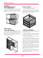
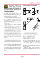
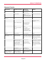
ABCDEF ABCDEF IM Issue 8a May 2010 Installation and Maintenance Service Manual for Air Handling Equipment CONTENTS Installation and Maintenance Service Manual for Central Station and Packaged A.H.U's Index Contents Page INTRODUCTION 1-3 Health & Safety, Safety Symbols, Receipt of Plant, Off Loading, Unit Protection, Unit Storage, Unit Positioning, Methods for Offloading INSTALLATION General, Location, Section to Section Joints, Leakage Tested Units, Weatherproof Units, Ductwork Connections, Pipework Connections, Electrical Connections, Motor Wiring Diagrams, Motor Starting Methods, Filters, Control Dampers, Final Inspection COMMISSIONING General, Commissioning Checklist, Anti-vibration Mounts, V-Belt Drives, Fan and Motor, Refrigeration Systems, Control Systems, Safety Interlocks, Warranty Claims MAINTENANCE General, Fans, Drive Gear, Belt Tensioning, Alignment, Motors, Bearings, Filters, Coils, Humidifiers, Legionella Check, Electric Heaters, Bulkhead Lights, Refrigeration Systems, Specialised Equipment, Maintenance Schedules SERVICE CONTRACTS FAULT FINDING General Faults, Refrigeration System Faults 4-9 10 - 12 13 - 18 18 19 - 21 INTRODUCTION INTRODUCTION HEALTH & SAFETY During installation, commissioning, operation and maintenance of air handling units, operatives may be exposed to hazards including, but not limited to, rotating components, refrigerants and high voltage electricity. If misused or handled improperly, each of these items has the potential to cause bodily injury or death. It is the obligation and responsibility of all personnel to identify and recognise these inherent hazards, protect themselves and to proceed with care and consideration to safety when completing their tasks. Failure to comply with any of these requirements may result in serious damage to the equipment or the property in which it is located as well as resulting in personal injury or, in extreme circumstances, death. This manual is intended for use by authorised operating and service personnel, who should possess the appropriate training and skills to enable them to perform their tasks competently and safely. It is essential that before performing any task, the operative shall have read and understood this manual together with any other documents referenced. The operative should also be familiar with and comply with all governmental standards and regulations relating to the task in hand. SAFETY SYMBOLS The following symbols are used to alert the reader to potential hazards. Notes are intended to clarify or highlight additional information. Cautions identify hazards that could lead to damage of the equipment. Warnings indicate potentially hazardous situations, which could result in serious personal injury or death. DANGER Danger Indicates imminently hazardous situations, which could result in serious personal injury or death. H Before commencing any activity, please ensure that: All appropriate method statements and/or risk assessments have been raised, served, are in place and are adhered to prior to carrying out any activity. appropriate Personal Protective The Equipment (PPE) attire is worn relative to the operation being carried out. (Refer to the specific risk assessment.) The unit supplied meets with the standards written into the specification and is suitable for the actual job application. Adequate site plant and lifting gear is available to lift and position the unit to the manufacturers recommendations. Electrical equipment is rated, connected and earthed in accordance with I.E.E. Regulations and local by-laws where appropriate. Personnel do not enter the unit whilst the fan is running. The plant is fully isolated from the mains supply and allowed to run down for a minimum of five minutes before opening any access door prior to the commencement of any maintenance work. Upon conclusion of maintenance work the unit is left in a clean state with all access doors and panels correctly fastened and locked. Fan and motor drive guards, fan inlet guards and door guards are not fitted unless DANGER specified. The fan and motor are naturally guarded whilst in operation by the unit panel work and therefore do not come under the category of “open, unprotected plant”. RECEIPT OF PLANT The ensure during ensure unit should be examined upon receipt, to that no visible damage has occurred transit, and the advice note checked to that all items have been received. If damage or delivery shortages are discovered, the carrier should be immediately informed. Dalair Limited should be notified within three days of receipt, with a written confirmation sent within seven days. Dalair Limited can accept no responsibility for damage by unloading from carrier or for subsequent damage on site. Page 1 INTRODUCTION INTRODUCTION OFFLOADING UNIT STORAGE The simplest method of offloading is by forklift truck. If this is not possible, unit sections should be lifted by crane, utilising the lifting holes or lugs provided in the structural base frame. These are provided for the facility of inserting lifting shackles and nylon, web type slings. If the unit is not to be installed immediately, it should be stored in a clean, dry area. If stored externally, it should be adequately protected from the weather. Dalair Limited should be notified of the method of offloading in advance, as this affects the way in which the unit sections are loaded onto the delivery vehicle. Recommended methods of offloading are shown on page 3. Keep sections upright – DO NOT TILT. Timber packs should be utilised to avoid abrasion. Spacer bars should also be fitted, where necessary, to prevent the slings from slipping. Where sections are fitted with a roof, additional timber packing must be utilised to ensure that the slings do not bear on the roof structure and that all forces are transferred to the section framework. Failure to utilise additional timber packing will result in damage to the roof. Ensure that sections are offloaded onto a prepared, flat sound base in an upright and level position. To prevent damage it is recommended that the recipient obtain expert advice from a craneage specialist. Refer to general arrangement drawings for section weights. All lifting equipment is to be supplied by others. Avoid unnecessary jarring or rough handling. It is important not to drop the units as this may result in permanent damage to the internal components. During the storage period, it is advisable to slacken the drive belts and to rotate the fan shaft two or three turns every week to eliminate false brunelling of the fan and motor bearings. Before the unit is put into operation, the grease in the bearings should be checked for oxidation, a condition that is indicated by the grease hardening and taking on the appearance of varnish. Fan and motor pulleys should be checked periodically for rust and sprayed with penetrating oil as a rust preventative. In addition all dampers should be rotated and lubricated as necessary. UNIT POSITIONING To alleviate the risk of damage, consideration should be given to using the services of Dalair Limited or a plant movement specialist when moving unit sections into their final position. The preferred method is by forklift or hand pump trucks with timber packing to avoid abrasion. Mechanical skates, rollers, pinch bars and jacks may also be utilised as necessary, but due care should always be taken to avoid damage to the unit sections and finishes. Where unit sections are fitted with feet, it is essential that adequate timber packing be provided to ensure that all forces are transferred through to the base support channels. Failure to observe this will result in damage/misalignment of the support feet and unit section base frame. UNIT PROTECTION Unless otherwise specified, unit sections will be delivered to site covered in “shrink wrap” polythene, which should provide a more than adequate level of protection against inclement weather. Should alternative methods of unit protection be required, (i.e. timber, Corex, or flame retardant materials), Dalair Limited should be notified of the specific requirements at the precontract stage. The removal and disposal of all protective coverings is the responsibility of others. Unit section base frame Timber pallet or similar Forklift forks Support feet During offloading and positioning, it is vital that the air handling unit sections are kept upright on their bases. They must not be turned in any 90° or 180° plane otherwise severe damage will occur. Any known restrictions should be advised at precontract stage. Page 2 INTRODUCTION INTRODUCTION METHODS FOR OFFLOADING Page 3 INSTALLATION INSTALLATION GENERAL Units should be installed in accordance with good engineering practice and stand upright and level. The floor, foundation or supporting steelwork should be rigid, flat and level. The structure should be capable of supporting the weight of the unit including water or refrigerant in the coils. Dalair Limited are not responsible for the coordination of the supporting steelwork, concrete plinths or the like. LOCATION The unit should be located away from building flue stacks or exhaust ventilators to prevent possible reintroduction of contaminated air through the outside air intake. Ensure that provision has been made in the location of the unit to allow for the removal of all plant items for service and maintenance purposes. Sufficient room should be allowed for access to: Fans & motors Electric heater batteries Filter bags, auto-rolls and panels Coils and evaporative humidifiers, including their removal for long term maintenance Spray nozzles and pumps for spray coil modules Heat exchangers Thermal and desiccant wheels Dagger plates LEAKAGE TESTED UNITS Air handling units are manufactured and assembled to recognised industry standards and they will normally achieve the air leakage test classification specified when carried out in accordance to the HVCA Specification Guides DW143 and DW144. However, due to the stresses, strains and forces imposed during loading, transportation, off loading and site positioning, the air handling unit structures will move and panel seals will not always remain fully intact. It is therefore likely that re-sealing of the panels and joints may have to be carried out on site for the air-handling units to achieve the required leakage classification. Door locking mechanisms may also have to be adjusted. Dalair cannot be held responsible for the units failing a site leakage test if the above have not been carried out correctly. However, Dalair will be pleased to offer a service, at an additional cost, or provide suitable advice for any remedial works as required. Section-to-Section Joints Cleat and bracket detail IMPORTANT CONSIDERATION Sufficient clearance for U-traps on condensate drain and overflow connections should also be considered by the purchaser. (See Page 5) Intermediate Bracket SECTION-TO-SECTION JOINTS Standard Cleat Ensure that sections or section assemblies are positioned in their proper sequence and that the unit handing and reference is correct. Large Cleat Sections should be accurately aligned and abutted prior to bolting together using the fixings and gaskets provided. All units have a corner gusset for bolting the sections together. On larger units an intermediate joining bracket is added. Section-to-Section Joints Jointing gasket and mastic seal detail Incorrect installation will result in air leakage, air blow marks to the unit casings and unacceptable noise. It is recommended that a mastic seal be applied to the joint following assembly (See detail opposite). Page 4 Fixed Panel Jointing Gasket Fixed Panel Mastic INSTALLATION INSTALLATION WEATHERPROOF UNITS Units or assemblies are weatherproofed in the factory. Prior to final assembly of sectionalised units, the rubber gasket supplied should be fitted between the section-to-section joints. (See page 4, Section-to-Section Joint sketches.) A suitable outer sealant should then be applied, followed by the fixing of roof strips, supplied loose, to ensure a fully weatherproof seal. PIPEWORK CONNECTIONS General Pipework should be connected in accordance with good engineering practice, and particular care taken when connection is made to screwed fittings on the unit. All pipework must be adequately supported to ensure that no additional load is borne by the unit. Where supplied, ‘PN’ coil flanges will be loosely fitted in reverse. The correct fitting of all flanges is to be under-taken, on site, by others. Roof joint strip detail Coil Connections Allowance for expansion and contraction should be made when making connections to coils. The bulb of the thermostatic expansion valve for direct expansion coils should be securely fitted to the suction line prior to any equalising connection. Steam coils should be supplied with a good quality dry steam via the appropriate control method, with a steam trap preferably of the mechanical float type. DUCTWORK CONNECTIONS Ductwork may be connected direct to the air handling unit, with the exception of units where external spring isolators require a flexible connection allowing a movement of 25 mm in any direction. Ductwork, steelwork and any other services should not be supported off the unit. Each coil section should be individually trapped. Vertical rising condense lines should be avoided, unless pumped. If a frost coil is not fitted then appropriate action must be taken to prevent the coils from freezing. Please contact Dalair Limited for further information and advice. Steam Humidification Modules Please refer to the manufacturers installation instructions, contact Dalair Limited for further information. Suggested methods of fixing ductwork Condensate Drain Connections All condensate drain connections must be correctly trapped. Incorrect trapping can result in flooding within the unit and consequent flooding of the immediate area. Drain lines should be a minimum of the same size as the drain pan connection. They should pitch downwards continuously, with a minimum fall of 10mm per metre, to a tundish or other form of air break. There must always be an air break. All drain lines should be insulated where passing through any space where damage from condensation drip might occur. Fittings with cleanout plugs should be used at each change of direction in the drain line. Recommended condensate trap arrangements are shown in the diagrams on Page 6. Page 5 INSTALLATION Condensate Drain Connections ELECTRICAL CONNECTIONS Electrical components should be connected to the supply in accordance with the Institution of Electrical Engineers (I.E.E.) Regulations and local by-laws where appropriate. Draw-through, Negative Pressure: 'S' trap arrangement In the case of three phase motors ensure that the rotation of the motor corresponds with the direction shown by the arrow on the fan frame. Be sure that the electrical fan motor is made using containment materials, to adjustment and also to allow the anti-vibration mounts. X Y MSP = Maximum suction pressure (in Pa) (Based on ‘dirty’ filter conditions) Dimension X = (MSP/10) + 50 (mm) Dimension Y = X/2 (minimum) For example if MSP = 1500Pa connection to the flexible cabling/ permit fan belt for movement of If safety-isolating switches are fitted to access doors they must be wired through the appropriate motor control circuits. Provision should be made for the installation of a fan run on control to prevent residual heat emanating from the heating plant damaging components such as the fan, motor, filters etc., when the unit is shut down. This objective may be achieved by: - Dimension X = (1500/10) + 50 = 150 + 50 = 200mm Dimension Y = 200/2 = 100mm Overall trap height = X + Y = 200 + 100 = 300mm Blow-through, Positive Pressure: Running trap arrangement A thermostat controlling the fan and ensuring that the temperature within the unit does not rise above 45°C in the event that air ceases to flow, Utilising a delay timer Airflow switches Motor Wiring Diagrams Typical connection diagrams are shown below: - Three Phase, Single Speed Motors Y Connection W1 W2 V1 V2 U1 U2 L3 L2 L1 L1 U1 X U2 Y Cables enter from left U1 W2 W1 L3 L1 U2 W1 W2 L3 V2 V1 L2 W2 V1 V2 U1 U2 L3 V2 L2 L2 Cables enter from right Cables enter from left W1 V1 L1 Cables enter from right MDP = Maximum discharge pressure (in Pa) (Based on ‘dirty’ filter conditions) � Connection W1 W2 L3 V1 V2 L2 Dimension X = 50mm (minimum) Dimension Y = (MDP/10) + 50 (mm) L1 U1 U2 L1 W2 U1 Cables enter from left For example if MDP = 500Pa Dimension X = 50mm Dimension Y = (500/10) + 50 = 50 + 50 = 100mm W1 L3 U2 V2 V1 L2 W1 W2 L3 V1 V2 L2 Overall trap height = X + Y = 50 + 100 = 150mm Cables enter from the left or the right U1 U2 Cables enter from right Page 6 L1 INSTALLATION INSTALLATION Motor Wiring Diagrams FILTERS Three Phase, Two Speed Motors The correct installation of air filters is an important requisite in the satisfactory functioning of any plant. It is necessary therefore to ensure that each filter is intact before use and only then installed in the manner recommended below. Two separate windings Y/Y 1W 2W L3 1V 2V L2 L1 L1 1U 2U L1 2U 1U Low speed 1W 2W 2W 1V 1W L3 L2 L3 2V L3 L2 1V 2V L2 High speed Low speed 1U 2U L1 High speed Two separate windings �/� 1W 2W L3 1U 2U L1 2U 1U Low speed 1W 2W L2 L3 L3 2V 2W 1V 1W L2 L3 1V 2V L2 High speed Low speed 1U 2U L1 High speed Dahlander-connection �/YY Unless otherwise stated in our offer each filter bank is supplied with a loose inclined gauge manometer, which should be fitted in a horizontal manner adjacent to the filters and connected with the plastic tubes provided. Spare Filters 1V 2V L2 L1 L1 To establish a dirty filter condition and as an aid to check the entire installation, a filter measuring device is required to be fitted across every bank of filters to enable accurate measurement of the air pressure drop. If stated in our offer, the AHU may have been supplied with a spare set of filters. Any loose or spare filters should be stored in a dry & clean environment. Should you require spare filter media then please contact Dalair for information. Auto-Roll Filters Please refer to the manufacturers installation instructions. Contact Dalair for further information. 1W 2W L3 1V 2V L2 L1 L1 1U 2U Panel & Bag Filters Side Withdrawal L1 2U 1U Low speed 2U 2W 1U 1W 1W 2W 1W L3 1V L2 2V 2W L3 L3 2V 1V L2 1V 2V L2 Low speed High speed 1U 2U Filters are inserted by sliding them into rails provided. Blanking elements, where necessary, are factory fitted at the end of the rails by Dalair. L1 High speed Dahlander-connection Y/YY 1W 2W L3 1V 2V L2 L1 L1 1U 2U L1 2U 1U Low speed 2U 1W 1U 2V 2W 1W 2W 1V L2 1W L3 2W L3 1V 2V L2 L3 1V 2V L2 High speed Low speed 1U 2U L1 High speed Motor Starting Methods Motor Power Range 0.18 to 3 kW 4 to 5.5 kW 7.5 to 90 kW DOL Star/Delta Inverter Star Delta N/A N/A N/A Star/Delta Star Delta Delta Recommended tightening torque M5 = 4Nm, M6 = 7Nm and M10 = 14Nm Page 7 INSTALLATION INSTALLATION FILTERS Panel & Bag Filters Front Withdrawal Front withdrawal bag type filters are fitted by inserting them squarely into the frames and are retained by spring holding clips. Bag filters should be inserted with the pockets in the vertical position. HEPA Filters Front Withdrawal These filters are generally supplied loose to be fitted on site when the installation is complete. Due to the high efficiency of these filters and the often 'clean room' standards that they must attain, the utmost care should be taken when replacing these filters to ensure there is no contamination of the system. Carbon Filters Carbon filters are supplied loose to be fitted on site, when the installation is complete. The filters must be stored in a clean, dry environment and all packaging must remain in place until the time of use. This type of filter has a limited shelf life and, consequently, should be regularly inspected and changed. CONTROL DAMPERS Dalair Limited only accepts responsibility for damper actuators and linkages supplied as part of the equipment order. Where control damper actuators and linkages are supplied and fitted by others, these items should be set up in accordance with the control manufacturers instructions. Airflow control dampers may be operated with pneumatic or electric actuators. If it is necessary to use a linkage between the damper actuator and the damper drive shaft, they should be positioned a minimum of 350mm and maximum 1200mm apart. The linkage may be difficult to adjust on shafts that are less than 350mm apart and, if the shafts are more than 1200mm apart, the connecting linkage may lack stiffness to operate the dampers. Ensure that all spring return actuators have stopped running and completed their stroke. If not, loosen the connection and let the actuator drive until the motor stops running. Adjust the damper blades to the desired position and retighten the actuator connection. After power has been supplied to the unit, the dampers should be checked to ensure that they operate freely and close tightly. Adjustment of the linkage may be required. Page 8 INSTALLATION INSTALLATION All dampers, actuators and linkages must be checked prior to applying power to ensure that nothing will obstruct the operation of the dampers. Do not overdrive damper actuators as this may result in damage to the damper. Typical linkage arrangements Linkage adjustment A linkage may be fitted between a control damper and actuator either in situations where the actuator cannot be fitted directly to the damper drive shaft or between the fresh air and return air dampers of two-way mixing boxes, Initially, establish the direction of rotation of the damper drive shaft(s) and the actuator. If a spring return actuator is fitted, ensure that it has completed its stroke. Manually rotate the actuator to the position that is required for the closed position of the damper operated by the crank arm, then rotate this damper to its mid stroke. Where the direction of rotation is identical, install the crank arms so that are parallel and at the same angle. When the direction of rotation is opposed, install the crank arms so that they are parallel but at 180° to each other. At this stage the crank arm on the damper shaft should be secured, but the crank arm on the actuator should be free to rotate. Attach the push rod between the ball joint connectors on both crank arms and tighten the ball joint screws only thumb tight. Manually rotate the crank arm on the actuator to drive the linkage and the damper shaft through its full stroke, to ensure proper damper action. Return the damper with the crank arm to it’s closed position. Tighten and secure the crank arm of the actuator. In the case of 2 way mixing boxes, the damper driven directly by the actuator should be manually rotated to the fully open position prior to tightening the crank arm on the actuator. While pushing the damper operated by the crank arm closed, tighten the ball joint screws to secure the drive rod. Run the actuator back and forth through its full stroke and check for proper damper and linkage operation. Adjust the linkage if required. In some instances, e.g. the face and by-pass damper of a plate heat exchanger, the damper may be operated by a bracket attached directly to one of the blades rather than a crank arm fitted to a drive spindle. This type of linkage is often more difficult to set up and adjust. In these circumstances, Dalair Limited recommends the use of a bracket fitted with a knuckle joint, which makes provision for changes in the geometry of the drive rod as the damper is opened and closed. 1. 2. 3. 4. Remote actuator, same direction of rotation Remote actuator, different directions of rotation Linked fresh air and return air dampers Plate heat exchanger face & by-pass damper with remote actuator showing knuckle joint FINAL INSPECTION After installation of the unit, inspection should be carried out. a thorough This should include inspecting the inside of the unit and removing debris and tools, which may have been left behind by on site contractors. Fan impellers, scrolls and outlets should similarly be inspected. Ensure that transit protection fittings are removed from the fan/motor base frame, all bearings are adequately greased and that all traps are primed. Replace any panels, which may have been removed and close all access doors, ensuring that the door sealing gaskets have not been damaged. Page 9 COMMISSIONING COMMISSIONING GENERAL ANTI-VIBRATION MOUNTS The unit is supplied with access doors, which should be closed whenever the unit is in operation. Before commissioning ensure that the unit has been completely assembled, as described in the installation section. Remove the transit protection fittings from the fan/motor base frame, which are to be found adjacent to the four antivibration mounts. Commissioning checklist Unit received undamaged Equipment received as ordered Unit positioned and assembled in accordance with installation instructions Fan base shipping restraints removed Anti-vibration mounts adjusted Check electrical supply voltage Check tightness of all electrical connections Check alignment of fan and motor pulleys Check taper lock bushes are tight Check fan belt tension Check any additional bearings and couplings where fitted Manually rotate fan impellers and motors to ensure freedom of movement Check and prime condensate drain traps Check all filters are fitted Energise momentarily to check correct fan rotation Check that all control system components, such as fan run on timers, airflow switches, etc., are wired correctly. Check control damper operation Check that ductwork is complete and that any fire dampers installed downstream of the fan are open Check access panels, doors are fitted and secure Check fan motor current draw Check all shaft bearings and belt tension after 24 hours of operation Note that the motor and drive are designed to operate against a given system resistance. If the system is not complete or access doors and panels are open, the motor rating will be exceeded and damage to the motor may occur. Do not operate fan motors in an overload amperage condition. Adjust each mount until the fan/motor base frame is level. Adjustment is achieved by releasing the locknut and screwing the central levelling screw into the mounting. When the equipment is level, tighten the locknut. V-BELT DRIVES Check the alignment of the pulleys and make any adjustment that is necessary. Clean protective oil or grease from pulleys or belts and tension the belts to manufacturers recommendation. (See the Maintenance section for further detail). FAN AND MOTOR Ensure that both the fan and motor run freely. Test run the fan, drive and motor to ensure that the fan is rotating in the correct direction. Adjust as necessary. When an inverter control is fitted, the connections between the inverter and the motor must be reversed. Check that all earth connections are intact. Check that the electrical current being drawn by the motor does not exceed the manufacturers recommendation quoted on the motor plate. If the motor is found to be overloaded, check the fan volume flow rate and the static resistance. If either of these exceeds the quoted unit design by more than 10% then contact Dalair Limited, as a modification may be required. Small motors are normally switched direct onto the mains. This method of starting is preferable for any size of motor as it gives the highest torque and utilises the most cost effective and least complicated starter. The only restriction is that imposed by the Supply Authority due to the limitation of the feeder circuit capacity. NOTE: All motors up to 5.5 kW, unless otherwise stated, are assumed to be direct on line starting. Above this rating, provision is usually made for star-delta starting. When the Supply Authorities have a limit for stardelta starting, autotransformer starting is used when the limit is exceeded. Page 10 COMMISSIONING COMMISSIONING REFRIGERATION SYSTEMS Commissioning Procedure All work on refrigeration systems should be carried out by an approved and qualified refrigeration service engineer. Prior to setting up the refrigeration circuit the air volumes on the evaporator must have been proven to be between 100% and 110% of design. CAUTION! Refrigeration systems contain gas at high pressure. Due care should be taken when connecting or disconnecting any components or gauge sets. Run the main supply (evaporator) fan and check running currents on all three phases. Set the overload. Check the main supply (evaporator) fan air volume. Always ensure that the correct PPE attire is worn and refer to the appropriate COSHH data sheet, risk assessment and method statement. Isolate the compressor by its fuses/circuit breakers and carry out a full controls and functional check. DANGER Do not use a naked flame if refrigerant gas is present in any appreciable quantity in the local area. Units are shipped with a holding charge of refrigerant. This is NOT a full charge and refrigerant will have to be added on site. Service Valves The liquid and suction line service valves are shipped from the factory front-seated and closed with the valve stem in the maximum clockwise position. The discharge service valve is shipped in the open position, and it will only be used if the compressor requires service. The liquid and suction line service valves have a 1/4" male flare access port for evacuating, charging and pressure checking the system. NOTE! Never remove a cap from an access port unless the valve is fully back-seated with its valve stem in the maximum counter-clockwise position as the refrigerant charge will be lost. ALWAYS USE A REFRIGERATION VALVE WRENCH TO OPEN AND CLOSE SERVICE VALVES. Safety Features Compressor motors are internally protected against over current and excessive temperature by a line-break motor protector. Compressors are equipped with crankcase heaters to discourage refrigerant migration into the compressor sump during the off cycle. The pump down, if present, positively closes the evaporator during the off cycle, storing the system charge in the high side and isolating the compressor sump from refrigerant. Once the above has been completed the refrigerant system may be charged as follows: - Initial Charging CAUTION! Where fitted, compressor crankcase heaters must be energised for at least 24 hours prior to charging and commissioning. Isolate the compressor via its service valves and shut the liquid line shut-off valves. Attach a vacuum pump to the high-pressure side of the system and pull the condenser and associated pipework down to a vacuum. Once a vacuum has been achieved connect the liquid connection of a refrigerant cylinder to this charging point and introduce liquid until the pressure stabilises. This will give a charge to enable vapour charging to take place with less risk of overheating the compressor through lack of suction gas cooling. IMPORTANT! This must be carried out with the compressor isolated by its fuses or circuit breakers to avoid the possibility of it starting as the pressure in the system rises and the pressure switches operate. Disconnect the charging manifold and connect across the compressor discharge and suction ports. Open all the service valves. Check the high and low-pressure switch settings against the commissioning details. Every unit is protected by both high and lowpressure controls mounted in the compressor section/housing. Every compressor is protected by an anticycle timer to prevent on/off cycling. These timers must be set at a minimum of 6 minutes, to allow a maximum of 10 starts per hour. Page 11 COMMISSIONING COMMISSIONING Final Charging CONTROL SYSTEMS Switch the compressor on and charge with vapour taking care to monitor the evaporating and condensing temperatures at frequent intervals. Also check that the compressor is running cool. In the event of the compressor body getting hot, stop charging and allow compressor to cool. Our warranty only extends to control systems supplied and commissioned by Dalair Limited. Charge each circuit to a full sight glass and to the correct evaporating and condensing temperatures. Check the superheat and adjust each expansion valve as necessary to obtain the design superheat. The evaporator air-on temperature must be to design to be able to charge the system correctly. Check the operation of both high and lowpressure switches. The low-pressure switch can be checked by de-energising the solenoid valve. The high-pressure switch can be checked by switching off the condenser fans. In the event that commissioning is undertaken by others, the operational warranty for the control system would then be the responsibility of others. SAFETY INTERLOCKS It is recommended that the user seek advice from a control system specialist to ensure that adequate safety features are provided to prevent severe damage caused through malfunction or component failure, e.g. damper malfunction or failure or excessive pressure. Consideration should be given to gas or electrical heaters and modulating burners to ensure that sufficient safety interlocks are provided. CAUTION! Monitor the high pressure constantly during this test. If the pressure rises above 420 P.S.I (29 Bar) shut the compressor down. Failure to do this may result in the compressor internal relief valve blowing which would then necessitate the compressor being replaced. Check that the controls operate correctly to maintain the return/room air at the correct temperature. Note all details on the commissioning sheet supplied and return one copy to Dalair Limited. Proof of correct commissioning shall be requested in the event of a warranty claim. Replace all access connections, Schrader caps and valve caps to ensure that refrigerant loss cannot occur, and return any manual override switches to the 'AUTOMATIC' position. WARRANTY CLAIMS Any claim for inaccuracies in duty should be substantiated with a full commissioning report. Proof of correct commissioning may be requested in the event of a warranty claim. Page 12 MAINTENANCE MAINTENANCE GENERAL General fan maintenance A system of planned, regular maintenance will return dividends by averting possible costly repairs and unexpected periods of down time. It is the owner’s responsibly to provide the necessary maintenance of the air-handling unit. If system failure occurs due to improper maintenance during the warranty period, Dalair Limited will not be liable for any costs incurred to return the unit to satisfactory operation. (Common to all fan types) The unit must be manually isolated from the electrical supply and a period of 5 minutes DANGER allowed to elapse before any access door is opened for the purpose of general maintenance. FANS Units are generally fitted with belt driven, centrifugal fans, with the motor and drive gear located in the airstream. Dependant upon the design criteria, other fan types and drive arrangements may be supplied. These include direct drive, axial, plug and duplex fans. Extended shaft fans are used in situations where the motor and drive gear are required to be located out of the airstream. Fans can be offered to meet the ATEX directive where in-house certification is required. Refer to the general arrangement drawings for details of the type of fan and drive fitted. Additionally, each fan has its own identification plate, giving details of the manufacturer, fan size, serial number and type. Specialised and major servicing, such as the replacement of a damaged fan impellor, is beyond the scope of this manual. If it should become necessary, please refer to the fan manufacturer’s literature, which, if not included with this manual, can be supplied upon request. As a general rule, fans should be inspected at least twice a year. Any unusual noise or vibration when the fan is running should be immediately investigated and remedied, as this usually an indication of wear or imbalance in the fan system. Prior to carrying out any work on a fan it is imperative that: The power supply to the motor is switched off at the safety-isolating switch. A period of at least 5 minutes is allowed for the fan impellor to come to rest. Precautions are taken to prevent the accidental, uncontrolled running of the fan during the maintenance work. Access to the fan section is normally gained by removing the quick release panel to the side of the unit. Inspect the fan blades and remove any build up of dust by lightly brushing, using compressed air or a vacuum cleaner. If the impellor is coated with greasy dirt, it can be washed with a mild detergent or solvent. Gentle handling is essential. Steam or other high-pressure cleaners must not be used. Check the fan shaft and all bearings for signs of over heating and wear. Lubricate as necessary (See Bearings section, Page 15) Fan bearings may be replaced easily, although it may be necessary to remove small fans entirely from the unit. Inspect the flexible connection between the fan and unit for damage or wear and replace if necessary. Duplex fans Small duplex fans, i.e. two fans driven by one motor, may share a common drive shaft. Larger duplex fans generally have a flexible connection fitted between individual fan shafts. Where the connection between the fan shafts is a “universal joint” type coupling, it should be inspected for wear and greased as part of the regular maintenance programme. Where a “rubber tyre” type coupling connects the fan shafts, it should be inspected for signs of wear, (e.g. porosity or severe cracking), and replaced as necessary. Extended shaft fans When motors are mounted out of the air stream, the fan shaft and fan base steelwork are extended to penetrate the unit casework. Ensure that the fan shaft seal is intact and adequately packed with grease. Also check the condition of the rubber seals surrounding the fan base penetrations for signs of damage and replace if necessary. Direct drive fans Direct drive fans eliminate the need for belts or pulleys as the motor is directly connected to the impellor. Where fitted to direct drive fans, the “rubber tyre” type coupling connecting the motor and fan shaft should be visually inspected for signs of wear and replaced as necessary. Page 13 MAINTENANCE MAINTENANCE Drive gear (Belt driven fans) Ensure that the motor and fan pulleys are aligned and taper lock bushes are tight. The V-belt drives should be checked for wear and tensioned to comply with the appropriate motor manufacturers instructions. Replacement belts should be of the same specification and matching length as those originally supplied. Tensioning Forces Table Small pulley Belt diameter (mm) Section Force required to deflect belt 16mm per metre of span Newton (N) Kilogramforce (Kgf) SPZ 56 to 95 100 to 140 13 to 20 20 to 25 1.3 to 2.0 2.0 to 2.5 SPA 80 to 132 140 to 200 25 to 35 35 to 45 2.5 to 3.6 3.6 to 4.6 SPB 112 to 224 236 to 315 45 to 65 65 to 85 4.6 to 6.6 6.6 to 8.7 The high performance of modern belts, particularly wedge, cannot be achieved without correct tensioning. SPC 224 to 355 375 to 560 Z 56 to 100 5 to 7.5 0.5 to 0.8 Incorrectly tensioned belts can substantially shorten belt life and overload fan and motor bearings shortening their life expectancy. Over tightened belts can result in failure of the fan and motor shafts and bearings, and can cause nuisance tripping of the motor overload. A 80 to 140 10 to 15 1.0 to 1.5 B 125 to 200 20 to 30 2.0 to 3.1 C 200 to 400 40 to 60 4.1 to 6.1 Where multiple belts are fitted, always replace all belts as a set. Used belts will always be longer due to stretching. Belt Tensioning To check for correct tension proceed as follows: (1) Measure the span length. 85 to 115 8.7 to 11.7 115 to 150 11.7 to 15.3 Alignment Good alignment of pulleys is important. Poor alignment will result in belt flank wear. (2) At the centre of the span apply a force at right angles to the belt to deflect one belt 16mm per metre of span length. (3) Compare this force with value in the Tensioning Forces table. Span length Deflection 16mm per metre of span Correct FORCE Angled Pulleys are correctly aligned Shafts not in same plane Shafts are parallel and in same plane. Corrected by resetting shafts in the same plane. If the measured force falls within the values given the drive tension should be satisfactory. A measured force below the lower value indicates under tensioning. A new drive should be tensioned to the higher value to allow for the normal drop in tension during the running-in period. After the drive has been running for a few hours the tension should be checked and re-adjusted to the higher value. The drive should be subsequently tensioned at regular maintenance intervals. Make adequate provision for tensioning the belts during their life. The minimum take-up allowance is given in the table opposite. We recommend that a belt tension indicator be purchased (Contact Dalair Limited for further details). Angled Shafts not parallel Corrected by resetting shafts parallel. Ensure no deflection is taking place in supporting framework or shafts. Page 14 Offset Pulleys are offset Corrected by moving either pulley along the shaft until aligned MAINTENANCE MAINTENANCE MOTORS BEARINGS Check all motor wiring before starting up. The cables should be capable of carrying the full load current of the motor (see motor nameplate) without producing over-heating or an undue voltage drop under starting conditions. Terminal screws and fixing bolts should be tight. “Sealed-for-life” fan and motor bearings are generally fitted as standard and consequently maintenance is not required. Ensure the starter is compatible with the motor. Ensure the motor can be isolated from the mains. Remove the fan cover and ensure that all air-inlet holes are unobstructed. Clean any buildup of dirt and fluff from behind the fan and along the ribs of the frame. Motors fitted with ball and roller bearings are dispatched with the bearing housings correctly filled with grease, which under normal conditions is sufficient to last at least two years. The annular clearance between the shaft and bearing covers is very small so that the bearing housing can retain the grease and keep out dust and dirt. Should the grease melt for any reason, leakage will occur but, provided that the correct quantity of the correct grease is used, no trouble should be experienced. Bearing lubrication can be conveniently carried out when the motor is stripped for periodic cleaning and inspection on a routine basis. Over lubricating bearings, particularly on high-speed motors, causes the bearing to run extremely hot and the grease to become thin and leak out. BP Energrease LS3 is recommended for the majority of applications as its lubricating properties are retained over a wide temperature range (-20°C to +120°C). Any other good grade of lithium base grease with an i.p. penetration 185/250 may be used, such as Shell Alvaniar 3. Other bearings should be regularly checked and re-packed with a lithium based grease Shell Alvaniar R3 Lithium +180°C, C3 as necessary. Fan bearings are “lifelong” lubricated for 20,000 or 40,000 hours of operation. However, in heavy-duty operational conditions, maintenance intervals are to be established by the operator. If no greasing intervals are specified, they lie nominally above 8,000 operating hours. Hence re-greasing must take place at least once yearly. Depending upon operating conditions, it may become necessary to re-grease several times, as determined by the operator. For motor bearings, please refer to the details as explained in the adjacent motor section. It may be more economical to replace motors of small size that develop faults rather than to try to change bearings. FILTERS Filters should be inspected at monthly intervals under normal conditions or as indicated by manometer reading, where fitted. For typical dirty pressure drops, please refer to the general assembly drawings or the appropriate catalogue. As a general guide panel filters would not normally exceed 150Pa and bag filters would not normally exceed 250Pa. If there is any doubt as to whether the old and the new grease will mix it is recommended that the old grease is cleaned out and the bearing recharged with new grease so that the complete assembly including caps, is approximately 50% full with the grease in close contact with the race, and not merely smeared inside the bearing cover. BP Aeroshell No. 5 should be used for low ambient temperatures down to – 40°C. Rotation It is essential that the direction of rotation of the driving motor be checked. This check should be a visual one of the direction of rotation of the free shaft with the motor finally connected to the supply. Reversal of rotation can easily be carried out by changing over any two supply leads at the starter. Where an inverter is fitted, the connections must be reversed between the inverter and motor. Page 15 MAINTENANCE MAINTENANCE COILS ELECTRIC HEATERS Coils should be inspected every three months to ensure that there is no build-up of dirt between the fins. Any dirt found should be removed by using a high-pressure air or steam jet. In correctly filtered systems, no maintenance is required other than periodic checking of the fasteners and electrical connections for security. Inspect and remedy any coil connection leaks. Coil freeze protection must be provided in installations where any part of a water coil may be subjected to temperatures of 0°C or lower. If a coil is not in use, it is recommended that the coil be completely drained and the inside of the tubes be blown dry with compressed air. Dalair Limited will not be responsible for water coils damaged by freezing. If nuisance tripping of an electric heater occurs, the most likely cause is low air velocity over the heater elements. This may be due to dirty filters, too low a speed setting or user adjustment to dampers remote from the unit. Ensure that the thermal cut out switch is sound and operating correctly. BULKHEAD LIGHTS HUMIDIFIERS Always switch off and isolate before checking or changing the lamp. Periodically check the tightness of screw type lamps as these have a tendency to work loose. Check and maintain any water treatment that may be appropriate. Clean any sediment from the drain tray and connections and also clean and repair any areas of corrosion. Standard bulkhead lights Check that the replacement lamp is the correct type, paying particular attention to the voltage and wattage. Spray Coil/Washer Humidification Module Check all nozzles on the spray tree and clean as necessary in order to yield the full spray pattern. Incandescent lamps are type GLS, screw cap type E27, 60W, 240V 50Hz. Ensure that the pump inlet strainer is clean. Check that the pump is handling the correct volume of water and that it is operating smoothly and quietly. Check that there are no leaks, particularly at the shaft seal. Ensure that the motor is not overheating. Remove and clean all filters. Check the tripping time for the motor overload unit, and ensure that all controls are operating in a satisfactory manner. Wetted Cell Humidification Module Inspect pump operation as described in the previous section. Ensure sump drainage is clear to allow the flow of water under flushing cycles. Wetted cell humidification systems must not be supplied with softened water. LEGIONELLA CHECK At three monthly intervals take dip slide samples of cooling coil, exhaust heat recovery coil and humidifier condensate drip tray water and send for analysis. At three monthly intervals also take dip slide samples of evaporative humidifier / cooler drains / water reservoirs under the requirements of the legislation in relation to the Control of Bacteria in Water Systems. Fluorescent lamps are type PL, single turn, two pin cap type G23, 9W, 240V 50Hz. To replace a lamp, remove the diffuser by unscrewing the two fixing screws. Remove the old lamp and fit the replacement. Refit the diffuser, ensuring that the gasket seal remains intact. Do not over tighten the fixing screws. An effective seal can be achieved with moderate tightening of the screws. Externally maintainable bulkhead lights Older units are fitted with externally mounted standard bulkhead lights mounted within a purpose made, coated sheet steel box, hinged on one side and secured with a retaining screw. Remove the retaining screw and open the box to gain access to the bulkhead light. Lamp replacement is as described above. Newer units are fitted with dichroic lamps housed within polycarbonate terminal boxes. Dependent on customer requirements, these may be 240V or 12V. (12V lamps have a transformer fitted within the terminal box.) To replace the lamp, remove the terminal box cover by unscrewing the four fixing screws. Grip the sleeved lamp holder cover and put it out of the terminal box to reveal the lamp. Remove the old lamp and fit a new lamp of the same voltage. Push the sleeved lamp holder cover back into position and refit the terminal box cover, ensuring that the gasket seal is remains intact. If results are positive disinfect all associated components of the air handling unit including all drain trays, wash down sections and condensate trap arrangements. Page 16 MAINTENANCE REFRIGERATION SYSTEMS All work on refrigeration systems should be carried out by an approved and qualified refrigeration service engineer. CAUTION! Refrigeration systems contain gas at high pressure. Due care should be taken when connecting or disconnecting any components or gauge sets. Always ensure that the correct PPE attire is worn and refer to the appropriate COSHH data sheet, risk assessment and method statement. Do not use a naked flame if refrigerant gas is present in any appreciable quantity in the local area. Dirt should not be allowed to accumulate on the condenser coils or other parts in the condenser air circuit. Clean as often as necessary with a brush, vacuum cleaner attachment or other suitable means. Condenser fan motors are generally equipped with factory lubricated, sealed bearings and do not require any maintenance. A filter-drier is installed in the liquid line of every system to prevent damage from dirt and moisture. When replacing a filter-drier do not allow it to be exposed to the atmosphere for an extended period of time, as once it absorbs moisture from the atmosphere, it loses its effectiveness. Refrigeration Shut Down Periods Compressor Motor Burnout (Clean-up Procedure) When a hermetic motor burns out, the stator winding decomposes forming carbon, water and acid, which contaminate the refrigerant systems. These contaminants must be removed from the system to prevent repeat motor failures. Determine the cause of the burnout and make any necessary corrections. Check control panel for blown fuses, welded starter contacts, welded overload contacts or burned out heater elements. Check compressor terminal plate for burned or damaged terminals and insulation, and shorted or grounded terminals. Check wiring for loose power connections. Check for high or low voltage. Close compressor suction and discharge service valves and bleed refrigerant from compressor. Save remaining refrigerant in system. Remove the suction and discharge shut-off valve bolts and all other connections. Remove the damaged compressor and replace with a new compressor. On severe motor burnouts, be sure that the shut-off valves and suction or discharge lines are not contaminated. If they are, they should be thoroughly cleaned or replaced before being connected to the replacement compressor. Install a new liquid line filter-drier. In the event of a shut down of the unit for more than three weeks we recommend the following actions: - Evacuate and dehydrate the replacement compressor and check to see that the oil is at the correct level. Shut down procedure Place compressor in operation and, after a period of four hours, check the compressor oil for discolouration and/or acidity. If the oil shows signs of contamination, replace the oil charge and filter driers. Pump down the compressor. Shut the compressor service valves. Isolate the compressor by its fuses, circuit breakers or local isolators. Start up procedure Restore power to unit. Open all service valves. CAUTION! Where fitted, ensure compressor crankcase heaters are on for at least 24 hours prior to starting the compressor. Switch the compressor on and check refrigeration circuit readings. NOTE! Never remove a cap from an access port unless the valve is fully back-seated with its valve stem in the maximum counter-clockwise position as the refrigerant charge will be lost. ALWAYS USE A REFRIGERATION VALVE WRENCH TO OPEN AND CLOSE SERVICE VALVES. Check the oil daily for discolouration and acidity. If the oil remains clean and acid-free, the system is clean. If the oil shows signs of contamination change both the oil and the filterdrier. Repeat this procedure until the system is clean. SPECIALISED EQUIPMENT For the maintenance of specialised equipment, such as Indirect and Direct Gas Burners, Thermal Wheels, Desiccant Dehumidifying Equipment and any other equipment not detailed in this manual, please refer to the original manufacturer’s literature which will be supplied upon request. Page 17 MAINTENANCE MAINTENANCE MAINTENANCE SCHEDULE Check last maintenance report and intervening service reports. Pay particular attention to items mentioned in the latter. Routine maintenance Generally clean the unit. Maintain all surfaces as necessary treating any areas of corrosion. Clean drain trays and repair any areas of corrosion. Check all access doors for leakage and adjust locks if necessary. Replace any gasket materials if required, especially on filter modules. Assess the fan and motor bearings. Check for evidence of wear or overheating. Monthly Check condition of filters. Change if required. 2/3 Monthly Check all electrical connections and components for signs of overheating or arcing. Check cleanliness of fin coil banks and heat exchangers. Clean as necessary with soft brush or vacuum. Check fin coil banks and heat exchangers for signs of contamination. Disinfect as necessary. Check fan belt tension and pulley/belt wear. Use tensioning tables. Check condition of filters. Change if required. Check condensate drains are clear and ensure that water can flow away freely. Check drain trays for cleanliness. Wash with diluted disinfectant solution and rinse. Clean unit casing and action any rust spots. Where fan shafts extend through A.H.U. casework ensure that the shaft seal is intact and adequately packed with grease. Where fitted, filter manometer gauges should be checked, topped up with manometer fluid and zeroed as necessary. Yearly Tighten all electrical terminals within unit, motors, heaters, compressors etc. Inspect coil and vacuum coil faces to remove dust. Check filter rubber seals and replace if necessary. Inspect for corrosion and treat with rust inhibitor prior to touching up with paint. Check all earth connections. Additional 2/3 monthly checks for refrigeration systems Check evaporating and condensing temperatures and suction and discharge pressures. Check evaporator superheats. Check refrigerant charge level. If short of refrigerant check for leaks, repair and recharge. Carry out routine leak test with suitable leak detector with special reference to all screwed joints and valves. Check all pipework for signs of chafing or damage. Check compressor currents. Check all capillary lines for signs of chafing or fatigue. Check the condition of all pipework including vibration eliminators. Check operation of safety pressure switches. Recommended Spare Parts List 1 year schedule 4 sets of disposable filters 1 set of fan belts 1 belt tension Indicator 3 year schedule 12 sets of disposable filters 3 sets of fan belts 1 set of fan bearings 5 year schedule 20 sets of disposable filters 6 Monthly Grease fans with extended lubrication points. Lubricate locks and hinges and adjust as required. Check control damper blades for freedom of movement. Clean and lubricate damper blade bearings. Check operation of damper actuators and linkages through a complete operating cycle. Adjust as necessary. 3 sets of fan belts 1 set of fan bearings MAINTENANCE & SERVICE CONTRACTS Should you require after sales support, then do not hesitate to contact the Service & Maintenance department at our Head Office on 0121 556 9944 Page 18 FAULT FINDING FAULT General Faults Symptoms Possible Causes Checks & Corrections Unit not operating Main or local isolation off Check all isolators from mains to unit Fuse(s) failed Check all fuses in mains Replace blown fuses after correcting fault Unit not switched on Switch on External interlock fault Investigate and correct Control MCB tripped Re-set MCB after investigating and correcting fault Loose wire in control circuit Investigate and tighten wires Fan motor overload tripped Re-set after investigating power wiring and MCB. If it trips again, check motor and contactor Disconnect motor from wiring to check winding Motor runs but no volume Belts broken/drive pulleys loose Check drive belts and pulley security Replace damaged belts Water evident inside AHU casing Insufficient depth of condensate trap Check static differential pressure at component and rectify trap depth to suit Ensure multiple drain traps are individually trapped. Drain traps must not be connected to each other. Blocked filters affecting water seal in trap Change filters Check also for damper malfunction on air inlet AHU performance may be above design creating high air velocity through cooling coil and moisture carry over Re-check AHU performance and adjust as necessary Also ensure that the BMS control system, where fitted, has been set up and is operating correctly Humidification system may be over humidifying resulting in excessive moisture Investigate and if necessary recommission the humidification system System design over volume or pulleys incorrectly selected Isolate unit and refer to Dalair Limited for advice Unit not operating Power on Motors constantly trip out and running at excessive current Page 19 Notes Check for loose wires Do not link out without customers written consent FAULT FINDING FAULT FINDING Refrigeration System Faults Symptoms Possible Causes Checks & Corrections Notes Compressor not operating No power Fuses/Circuit breaker Check for loose wires Internal klixon tripped Loss of refrigerant Overload Too frequent cycling Low pressure switch tripped Loss of refrigerant Solenoid valve shut Low evaporator airflow Motor burn out Insulation check Replace compressor Loss of oil Check for signs of leak Liquid entering compressor Expansion valve stuck open Broken valves Replace compressor Low evaporator airflow Check and correct Dirty evaporator Clean Expansion valve fails to shut Replace and re-set Shortage of refrigerant Leak on pipework or components Low head pressure Air on condenser coil too cold Low condenser airflow Condenser fan failed Dirty condenser Clean System over-charged Remove excess refrigerant Non-condensable gases in system Evacuate and recharge system Noisy compressor Low evaporating pressure High condensing pressure Page 20 Disconnect compressor to check wiring Discard the excess refrigerant safely and in accordance with bylaws. FAULT FINDING FINDING FAULT Refrigeration System Faults Symptoms Possible Causes Checks & Corrections Compressor short cycles Shortage of refrigerant Re-charge to design Blocked filter drier Replace Low evaporating airflow Check operation of fan Check air filters Faulty expansion valve Replace and adjust superheat Broken or damaged compressor valves Replace compressor Expansion valve too far open Re-adjust as necessary Over-charged with refrigerant Reduce charge to correct level Broken suction or discharge valve Check and change as necessary Compressor ratio too high Check setting of high and low pressure switches and check that all evaporator and condenser fans are operating properly High suction temperature Reduce suction temperature by TXV adjustment or provide de-superheating Evaporating pressure too high Compressor running hot Page 21 Notes Discard the excess refrigerant safely and in accordance with bylaws DALAIR HEAD OFFICE BIRMINGHAM DALAIR LIMITED – HEAD OFFICE Southern Way, Wednesbury, West Midlands, WS10 7BU Telephone: 0121 556 9944 Fax: 0121 502 3124, 0121 505 2106 Email: [email protected] BIRMINGHAM DALAIR LIMITED – TECHNICAL CENTRE Dalair Limited, Blakeley Wood Road, Tipton, West Midlands, DY4 0QA Telephone: 0121 556 9944 Fax: 0121 505 4902 Email: [email protected] LONDON DALAIR LIMITED 338 Euston Road, Regents Place, London, NW1 3BT Telephone: 0208 544 8660 Fax: 0121 505 4902 Email: [email protected] MANCHESTER DALAIR LIMITED Metropolitan House, 16 Brindley Road, Old Trafford, Manchester M16 9HQ Telephone: 0161 888 2224 Fax: 0161 888 2227 Email: [email protected] GLASGOW AIRESALES SCOTLAND LIMITED The Mews, 19 Sandyford Place Lane, Glasgow, G3 7HS Telephone: 0141 204 4750 Fax: 0141 204 4755 Email: [email protected] BELFAST W J HOGG & COMPANY LIMITED 1A West Bank Drive, Belfast, BT3 9LA Telephone: 0289 077 8700 Fax: 0289 077 7508 Email: [email protected] Email : [email protected] Tel : 0700 4 dalair Web : www.dalair.co.uk Due to our policy of continued improvements in both design and performance, we reserve the right to alter details without notification