1
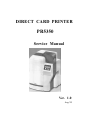
DIRECT CARD PRINTER
PR5350
Service Manual
Ver. 1.0
Aug.'05
Contents
Section 1 Overview
1.Outline of Equipment
1.Description of Equipment
2.Basic Specifications
2.Mechanical Operation
3.Electrical Operation
1.Electrical Block Diagram
2.Main Circuit Board
3.Interface Board
4.Operation Panel Board
5.Mechanical Actuators
Section 2 Setting Up
1.Setting Up
1.Caution for setting up
2.Space for installation
3.Connection to Host Computer
2.To put a ENCODER in the printer
1.Procedure to put in
Section 3 Operation Panel
1.Overview
2.Description of Operation Panel
3.Internal Modes of Printer.
1.Operation of Service Mode
2.Structure of Service Mode menu
3.Description of Service Mode
4.Structure of Service Mode Menu
Section 4 Maintenance
1.Maintenance List
2.Method of Maintenance
1.Cleaning Rubber Roller
2.Applying grease to Pulley Shafts etc.
Section 5 Replacement and Adjustment
1.Replacing Main Board
2.Adjustment after Main Board replaced
1.Adjusting the Print Position
2.Adjustment of Print Uniformity
3.Adjustment of Print Density
4.Adjustment of Sensor Level
3.Adjusting density of LCD Display
4.Adjustment for Card Thickness
Section 6 Troubleshooting
1.Troubleshooting with the display on the LCD
1.Description for the message on the LCD and meeting of recovery
2.Checking and repairing of the troubles
3.Troubles on communication with PC
2.Errors which can not be checked on the LCD panel
3.Card JAM Locations
Section 7 Appendix
1.Harness Connection
2,Electric Parts Layout
3.Parts Guide
Section 1 Overview
1. 1 Outline of Equipment
1.1.1 Description of Equipment
This equipment is a full color card printer to print image, characters and protective
overlay on a plastic card based on the data supplied from personal computer.
Printing method is dye sublimation heat transfer printing for color image and heat
melted ink transfer printing system for characters (black) and protective overlay. With
standard built in Flip Turn Block, both side printing is possible in single operation.
Magnetic encoding is possible on the magnetic stripe of the card by connecting
Magnetic Encoding Unit, which is available as an optional unit. Also, as an option, Heat
Roller Unit is available for printing hologram coating and thicker protective overlay.
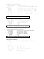
1.1.2 Basic Specifications
Printing method
Image Area: Dye Diffusion Thermal Transfer
Character Area: Molten Type Thermal Transfer
Protective Layer: Molten Type Thermal Transfer
Printing Media
PVC Card (Recommended Card by NISCA)
Size:Conform to JIS X 6301 (ISO standard CR -80)
Thickness:Conform to JIS X 6301( ISO standard CR-80)
Printing
300dpi ( 11.81dots/mm)
Resolution
Printing
Grayscale
Printing Size
Input:256 grayscale for each colors R,G and B
Output:256 grayscale control for each colors C,M and Y
Max. 85.5mm(card longitudinal)
× 54mm( card transverse direction)
Printing
Max. Entire are a
Arrangement Area
Printing Speed
45seconds per card excluding communication time at the
whole area printed as mentioned above.
Supply method
and capacity
100 cards(card thickness:0.76mm) ;supplied automatically
Interface
SCSI or USB 2.0 (Fixed in factory)
Power supply
Power
AC 100~ 240V
50/60Hz
120W max.
consumption
Equipment
dimensions
421mm(H)×271mm(W)×331mm(D)
(excluding Stack Box)
Equipment weight 13kg:Main body
13.8kg:Including optional magnetic encoder
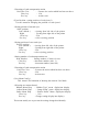
1.2 Mechanical Operation
This equipment consists of Card Supply Block, Flip Turn Block,
Card Ejection Block, Card Encoding Block and Card Rejection Block.
?
? Card Supply Block
Card Supply Box can contain up to 100 pcs of standard plastic cards(0.76mm
thick) so that a continuous printing of high volume card is possible.
The box is made of a transparent plastic for easy checking of the remaining card
supply and protecting the cards from dust. The card is fed from the bottom of the
pile and automatically transported in the printer. A weight plate is provided to
ensure the positive feeding of cards when the remaining cards becomes low.
Card separation is done by the gate at the entrance, which can be adjusted to
various thickness of cards.
? Card Cleaning Block
There are two rubber rollers with sticky surface to remove dust .One is for front side of a
card and the other is for back side of the card. Since this printer has this feature it is
possible to make prin ting process faster and clear at dual side printing.
It is necessary to clean them periodically to let them keep this performance.
See section4 for how to clean them.
?
Flip Turn Block
Turns the card for both side printing. This block also serves to switch the card
path to Print Block, Eject Block and Reject Block. It is possible to rotate the this
block manually. Never touch the part besides green color part when you need to
rotate this block manually.
?
Print Block
The card moves back and forth in the Print Block 5 times to be printed with 3
colors, black and overlay. Print Block consists of Card Transport Module, Print
Head Module and Ribbon Feed Module.
In the Card Transport Module, the card is transported by two pairs of capstan
rollers placed in front and behind platen roller. While printing, the nip release
mechanism works to eliminate the shock of the card entering the printing block and
provide a smooth and clear printing. Each roller is precisely driven by stepping
motor to minimize the color deviation and the side of the card is controlled to limit
skew. A high resolution ( 300 dpi) thermal head is used in the Print Head Module
for clear and high quality image printing. An even pressure is given to the thermal
print head by two coil spring located at both end of the head to maintain uniform
contact to the card. The thermal head is assembled in one independent unit so that
the replacement is made very easy. Also a user can replace the print head and
ribbon at front side by featuring front access system.
Ribbon Feed Module has Feed Bobbin, Transport Roller, Take-up Bobbin and
driven by each independent torque limiter so that the ribbon can be fed with
constant tension for stable printing. Take up bobbin is driven at two speeds, slow
for printing and high for non-printing, which makes the efficient operation possible.
?
Card Encode Block
Magnetic Encode Unit, IC Encode Unit, etc are available for this printer as optional
unit. By mounting the Encode Unit, printing of image and characters, encoding
Magnetic ( or IC ) data can be processed in one operation in one equipment. As the
Encode Unit can be mounted in the Printer, it does not require additional desk space.
?
Card Reject Block
If a trouble occurs while printing, the printer stops automatically. In such case, by
pressing "Clear" key, the card currently being printed will be ejected through
Reject Exit.
? Card Ejection Block
Card Ejection Block has a transparent card stack box. The printed cards are ejected
in this box and stacked ( 100 cards of standard thickness ).
The box has a cut out for easy removal of the printed cards.
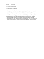
1.3
Electrical operation
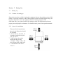
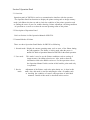
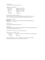
1.3.1.
Electrical Block Diagram
Operation
Thermal
Panel Board
Head
Main Circuit
Mechanical
Board
Actuators
Interface
Power Supply
Board
Unit
Printer Unit Block Diagram
The Printer Unit is controlled and driven with the following components.
? Main Circuit Board (PBA-MAIN)
Receives commands and data from the host through SCSI interface and controls the
operation of the Printer Unit, also controls the thermal print head according to the
image data.
? Interface Board (PBA-I/F- SCSI or PBA-IF-USB)
Controls the SCSI or PARALLEL interface.
For SCSI
:It has connector and terminator switch for SCSI interface and has
connector for optional units.
For USB
: It has a connector for USB interface and has connector for optional
units
? Operation Panel Board (PBA-OPEPANE)
Constituted with LCD, LED, Push Buttons, and controlled by the Main Circuit
Board.
? Power Supply Unit
Supplies DC24V, and DC5V to the Printer Unit and Optional Unit.
? Thermal Head
Supplies head energy for printing the image, characters and OP (over coat).
? Mechanical Actuators
Consists of sensors and the motors to transport the cards.
1.3.2
Main Circuit Board (PBA-MAIN )
There are CPU Block, Memory Block, Actuator Control Block.
Following items are the main components:
? 32 bit CPU (IC1)
32 bit single chip micro processor, activated on the clock of 12.5 MHz
? Flash Memory( IC8)
A memory of 4 M bytes for storing the firmware.
It can be downloaded through the SCSI or USB interface.
? SRAM(IC9)
1 M byte memory to be used for cash memory of CPU(IC1).
? EEPROM (IC4)
4K byte memory to record total frame number, number of errors, setting values of
the specific unit, etc.
? Serial interface driver (IC33)
Translated the signal of CPU to RS232C for communication with the built-in encoder
unit.
? SDRAM (IC14)
Memory of 16 M byte which stores the data of RGB +characters for 2 frames.
?
DSP (IC3)
Digital Signal Processor works for color changing or enhance of edge of an image.
? Control IC (IC2)
A Gate array to control the printer activated on the clock of 20 MHz.
This IC controls following items by setting from CPU
> To control the transfer of the image data to DRAM and also image rotating function.
> To control the thermal head
> Interface for SCSI or USB 2.0 control IC
> To control the LCD
> To supply driving signals for PM 1-3
> To generate the control signal for DM1
> To control sensors
1.3.3
Interface Board (PBA-I/F)
Interface board applies to SCSI-2 or USB 2.0 standard.
<SCSI 2 type interface board>
There are two "half 50" pin connectors on the interface board. Also, there is a
connector for connecting the optional device.
? Serial interface driver (IC4)
Translates the signal of CPU to RS422 level for the communication with the
attached optional equipment.
? SCSI Controller (IC2)
Operates on the clock frequency (OSC1) of 20MHz and controls SCSI bus.
? SCSI terminator (IC3)
An active terminator IC supporting the SCSI specification, which terminates the
SCSI
bus by the input of the switch (SW2) located on the backside of the printer.
<USB 2.0 type interface board>
There is B type connectors on the interface board. Also, there is a connector for
connecting the optional device.
?
Serial interface driver (IC2)
Translates the signal of CPU to RS422 level for the communication with the
attached optional equipment.
? USB controller ( IC1)
Controls the interface USB 2.0 bus. (generated by OSC1)
1.3.4
Operation Panel Board ( PBA-OPEPANE)
Operation Panel is used to indicate the current status of the Printer to the operator, to
change setting, execute printing, and clearing errors.
? LCD (IC1)
LCD panel of 16 characters * 2 lines. Displays the condition of the printer, setting and
changes of values, error messages, etc.
? LED1 - LED3
Indicate the Printer condition to operator.
? SW1 - SW3
Switches for operator to operate the Printer.
Note: Details of operating the Operation Panel is explained in Section 3,
Operation Panel.
1.3.5
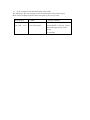
Mechanical Actuators
The Printer Mechanism consists of Sensors and Motors, etc.
<Input mechanisms>
Symbol
SN1
Component
Optical Sensor
Function
Detection of card empty at Card Supply
Block.
Detection of card position
(Just before Cleaning Roller ).
Detection of card position
(Just before Flip Turn Unit).
Detection of card position
(Just before Print Block).
Detection of card position
(to detect the leading edge of a card ).
Detection of the home position of Flip Turn
unit.
Detection of the angle of Flip Turn unit.
SN2
Optical Sensor
SN3
Optical Sensor
SN4
Optical Sensor
SN5
Optical Sensor
SN6
Optical Sensor
SN7
Optical Sensor
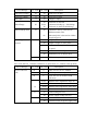
SN8
Optical Sensor
SN10
Optical Sensor
Detection of length of ribbon fed.
(taking up side)
Detection of mark on the ribbon.
SN11
Optical Sensor
Detection of print head position.
SN12
Optical Sensor
Detection of print head position.
SN13
Micro switch
SN14
Micro switch
SN15
Optical Sensor
SN18
Optical Sensor
Detection of open/close of Front Cover.
(with interlock function)
Detection of open/close of Top Cover.
(with interlock function)
Detection of card position
(just before encoder )only available when Encoder
set.
Detection of length of ribbon fed.
(supply side)
<Output Mechanisms>
Symbol
DM1
Component
DC Motor
PM1
Pulse Motor
PM2
Pulse Motor
Function
Rolls up Ink Ribbon.
Moves (up/down) Thermal Head
Drives rotation mechanism in Flip Turn Block.
Transports a card ( Card Supply Block)
Transports a card (Flip Turn Block)
PM3
Pulse Motor
Transports a card (Print Block)
HFAN
Fan Motor
Cools Thermal Head.
DFAN
Fan Motor
Cools Power Supply.
Section 2 Setting Up
2. 1 Setting Up
2.1.1 Caution for setting up
Dusty place must be avoided for using this equipment because the printing system of this
printer is especially sensitive to dust. When printing on the card with magnetic stripe , do
not place the printer at near the equipment which is emitting magnetic field.
Other than above, use general caution for setting up other OA equipments and choose
proper place with proper environment. For further details, please read operation manual.
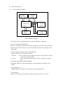
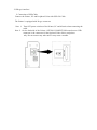
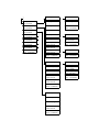
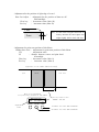
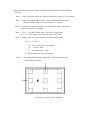
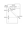
2.1.2 Space for installation
The space for the operation as
shown in the illustration should
be provided.
? At least 50 cm( 20 inch) of
clearance should be kept for
the Top Cover.
? Table to place the printer
should be able to hold
minimum 14Kg( 31lbs) and
have flat top and 4 rigid legs.
? It should not incline more
than 1? .
2.1.3
Connection to Host Computer with SCSI or USB
<SCSI type interface >
1) Connection of SCSI Cable
Connect the Printer, PC and Peripheral Units with SCSI Cable.
The Printer is equipped with two female connectors of 50 Pins (half type)of SCSI
specification. Use suitable SCSI cable with suitable connectors to match the PC and
Peripheral Units.
Note 1: Total length of the SCSI cable should be within 6 meters.
To ensure stable operation, within 4 meters is recommended.
Note 2: Please use the SCSI - II specification high impedance cable. In case of daisy
chain connection, operation may become unstable unless all cables are SCSI-II
specification.
Note 3: Turn OFF power switches of the Printer, PC and all units when connecting the
cable. The retaining hook should be securely latched.
Note 4: On the backside of the Printer, OPTION CONNECTOR located next to SCSI
connectors is the connector for the Optional Units of this card printer only.
Do not connect any other unit. It may cause a trouble.
Interface connectors
2) Setting internal SCSI Terminator.
The Printer has Active Terminator for SCSI-I and SCSI-II.
When using the Terminator, turn the switch at the back of the Printer ON (upper side).
(Turn OFF the power switch when operating this.)
To switch on
To switch off
Appearance of Terminator switch
3) Setting SCSI ID Number
The SCSI ID number can be freely selected from 0 to 7 through the operation panel of
the printer.
Default ID setting is 4.
Note 1: Do not set the same ID number as the PC and other peripheral units. ( It may
cause a trouble.)
When setting, check the ID numbers of the other units.
Note 2: When setting the ID number, turn OFF the power switches of PC and all other
peripherals.
<USB type interface>
1) Connection of USB Cable
Connect the Printer, PC and Peripheral Units with USB 2.0 Cable.
The Printer is equipped with B type connector
Note 1:
Turn OFF power switches of the Printer, PC and all units when connecting the
cable.
Note 2: On the backside of the Printer, OPTION CONNECTOR located next to USB
connector is the connector for the Optional Units of this card printer
only. Do not connect any other unit. It may cause a trouble.
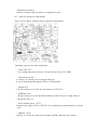
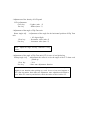
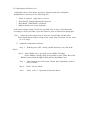
2.2 Installation of the Encoder Unit
2.2.1 Installing steps
Step 1 Turn OFF the printer power source.
Step 2 Remove RIGHT -COVER. ( Remove 2 x M-4 screws )
Step 3 Take the screw off to take out a slide for a card rejected .
Step 4 Insert the ENCODER into the encoder space of the printer with connecting the
two harnesses from the printer.
Step 5 Fix the ENCODR with the screw of which was removed in Step3.
Step 6 Put the small Exsit Cover on the RIGHT -COVER with two screws.
The Exit Cover and two screws are supplied with ENCODER.
Step 7 Put the RIGHT-COVER back to the printer and fix with 2 x M-4 screws
Step 3
Step 5
Step 4
Step 6
Section 3 Operation Panel
3.1 Overview
Operation panel of PR5300 is used as a communication interface with the operator.
The Operation Panel has functions to display the printer setting such as image memory
mode, ink ribbon selection etc and to check the condition of the printer operation such
as finding the cause of error for trouble shooting, Printer adjustment, che cking condition
of operation etc as well as to show the current operating status of the printer.
3.2 Description of Operation Panel
Refer to Section 4 of the Operation Manual of PR5350.
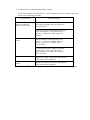
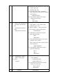
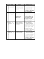
3.3 Internal Modes of Printer
There are three Operation Panel Modes for PR5350 as following
1. Normal mode Display the current operating status, such as error, of the Printer during
the print operation. The Printer is in this mode when the power is
turned ON. Refer to Operatio n Manual of PR5350 for the actual operation.
2. User mode
3. Service
mode
This mode is used to set the Printer conditions such as setting of
image memory, ink ribbon selection etc. Also, used to show the
information such as the ROM version etc. For the operation re fer to
the Operation Manual. In this section of this booklet, print mode only
is explained.
Adjustment of the Printer, such as the print density etc, is done in this
mode. Also, this mode is used for analyzing the cause of troubles such
as checking the condition of sensors and operation of individual
actuators. Details of this mode is described in this section.
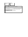
3.3.1 OPERATION OF SERVICE MODE
Service mode is the mode for the service person to adjust and check performance of the
printer. The image data in the printer is cleared when switched to and from the service
mode.
Switching to Service Mode
? To switch to service mode,
1. Return from the other mode to Normal Mode.
2. In the idle or error mode, keep the MENU key pressed till it becomes
Command Reception Mode. ("Input Command" appears on the LCD panel)
3. While pressing the MENU key, press EXE and CLEAR keys alternately
(about 8 times ) till the display changes from "Input Command" to "Service Mode".
4. Release the MENU key.
? Moving in the Same Directory
To move in the directory, press MENU key to change the menu. MENU will change
in the set order when the key is pressed.
? Execution of a menu
See section 3.3.2 and 3.3.3 for operation of current menu.
? Moving to the Lower Layer Directory
To enter into the directory of the lower layer from the present layer, press EXE key
at the appropriate menu.
? Returning to the Upper Layer Directory
To go one layer higher than the present, switch the menu to "Return to Parent Menu"
and press EXE key.
? Returning to Normal Mode
Switch the menu to "Return to Normal Mode" and press EXE key or switch the
menu to "Return to Parent Menu" and press CLEAR key.
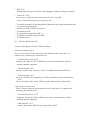
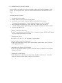
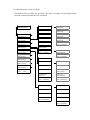
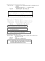
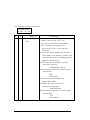
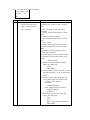
3.3.2 Menu Structure of Service Mode
The Menus of Service Mode are as follows. The part in rectangle will be displayed only
when the referred optional units are connected.
Service Mode
CLR:Back EXE Go
Adjustment Mode
EXE:sub menu
SN01 02 03 04 05
?
Sensor Check
EXE:sub menu
Actuator Check
EXE:sub menu
?
?
ISO Track1
EXE:Encode
SN06 07 08 09 10
ISO Track2
EXE:Encode
SN11 12 13 14 15
ISO Track3
EXE:Encode
SN16 17 18
JIS2
EXE:Encode
SN10 Analog Disp
Return to Parent
Menu (CLR/EXE)
Eject Position
EXE:sub menu
Auto Adjustment
EXE:Adj Start
User Menu Config
EXE:sub menu
Return to Parent
Menu (CLR/EXE)
?
IC-R/W Test
EXE:Entry/Eject
Encoder Check
EXE:sub menu
?
IC-R/W Check
EXE:sub menu
?
Stack Position
H.Roller Check
EXE:sub menu
?
Reject Position
Error Display
EXE:sub menu
?
Select Action
Position Adj.
Print Number
Position Adj.
EXE:Test Print
Card Pass Test
EXE:Start
Sensor Adj.
(Auto) EXE:Start
Return to Parent
Menu (CLR/EXE)
Return to Parent
Menu (CLR/EXE)
Return to Normal
Mode
(EXE)
Return to Parent
Menu (CLR/EXE)
Ribbon Menu Disp
?
?
Heat Total Time
Error Rate
Adjust Menu Disp
Error Log Disp
Status Menu Disp
Error Code rate
Return to Parent
Menu (CLR/EXE)
Error Log Reset
Return to Parent
Menu (CLR/EXE)
?
OD Adj. Color
OD Adjustment
EXE:sub menu
Zero Adj. Color
Cut Size Adjust.
Position Adj.
EXE:sub menu
OD Adj. Black
Return to Parent
Menu (CLR/EXE)
Uniformity Adj.
EXE:sub menu
Expanded Dt Adj.
EXE:sub menu
Sensor Posi Adj.
EXE:sub menu
LCD Adjustment
EXE:sub menu
F.Turn Angle Adj
EXE:sub menu
Return to Parent
Menu (CLR/EXE)
Zero Adj. Black
?
OD Adj. Clear
?
Zero Adj. Clear
?
Color Adjustment
EXE:Test Print
Color Adjustment
EXE:Test Print
Color Adjustment
EXE:Test Print
Return to Parent
Menu (CLR/EXE)
?
Horizontal Adj.
?
?
Data Cut Enable
Ribbon Sens Posi
Sensor to Head
EXE:Test Print
Return to Parent
Menu (CLR/EXE)
?
LCD Adjustment
Return to Parent
Menu (CLR/EXE)
?
Home Angle Adj
Vertical Adj.
F.Turn Ang.(PM1)
EXE:F_HOME
Black Shift Adj.
Pickup Angle Adj
(Auto) EXE:Start
Position Adj.
EXE:Test Print
Return to Parent
Menu (CLR/EXE)
Black Shift Adj.
EXE:Test Print
Return to Parent
Menu (CLR/EXE)
Uniformity Lower
Uniformity Center
Uniformity Upper
Uniformity Adj.
EXE:Test Print
Return to Parent
Menu (CLR/EXE)
?
Ribbon Mtr.(DM1)
EXE:HDRV
Ribbon Mtr.(DM1)
EXE:sub menu
Ribbon Mtr.(DM1)
EXE:LDRV
F.Turn Trf.(PM2)
EXE:CW HDRV
Headup Mtr.(DM1)
EXE:sub menu
Return to Parent
Menu (CLR/EXE)
Return to Parent
Menu (CLR/EXE)
?
F.Turn Trf.(PM2)
EXE:CCW HDRV
Pickup Mtr.(PM1)
EXE:sub menu
F.Turn Ang.(PM1)
EXE:sub menu
?
Headup Mtr.(DM1)
EXE:HOME
F.Turn Trf.(PM2)
EXE:sub menu
?
Headup Mtr.(DM1)
EXE:DOWN
Print Mtr.(PM3)
EXE:CW HDRV
Print Mtr.(PM3)
EXE:sub menu
?
Headup Mtr.(DM1)
EXE:UP
Print Mtr.(PM3)
EXE:CCW LDRV
Card Pass Test
EXE:sub menu
?
Return to Parent
Menu (CLR/EXE)
Return to Parent
Menu (CLR/EXE)
?
Print Mtr.(PM3)
EXE:CCW HDRV
Return to Parent
Menu (CLR/EXE)
Pickup Mtr.(PM1)
EXE:HDRV
Return to Parent
Menu (CLR/EXE)
?
F.Turn Ang.(PM1)
EXE:F_HOME
F.Turn Ang.(PM1)
EXE:R_HOME
F.Turn Ang.(PM1)
EXE:F_PRINT
F.Turn Ang.(PM1)
EXE:R_PRINT
F.Turn Ang.(PM1)
EXE:F_ENCODE
F.Turn Ang.(PM1)
EXE:R_ENCODE
Return to Parent
Menu (CLR/EXE)
?
Select Action
Print Number
Card Pass Test
EXE:Start
Return to Parent
Menu (CLR/EXE)
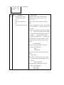
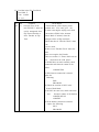
3.3.3 Description of Service Mode
(Adjustment Mode: printer adjustment menu)
Adjusting maximum optical density and print position etc.
Note: Do not make the value higher or lower than
you need. It may cause trouble.
*Optical Density (OD) Adjustment Menu
OD Adj. Color
: OD Adjustment for color image
OD Adj. Black : OD Adjustment for Black
OD Adj. Clear
: OD Adjustment for Clear (over coat)
Clear key : Make image lighter (Min. value :-7)
Exe key
: Make image darker (Max. value :7)
*Pre-heat Adjustment
Zero Adj. Color
Zero Adj. Black
Zero Adj. Clear
Clear key
Exe key
Menu
: Pre-heat Adjustment for color print
: Pre-heat Adjustment for Black print
: Pre-heat Adjustment for Clear (over coat) print
:
Decrement Value (Min. value :-7)
:
Increment Value (Max. value :7)
According to a card. In case that color come out even there is no data transferred or color
do not come out well, then use this adjustment.
*Print position adjustment
Horizontal Adj. : Position adjustment
0.085mm/digit (see
Clear key
:
Decrement Value
Exe key
:
Increment Value
for horizontal direction
figure below for adjustment direction)
(Min. value :-50)
(Max. value :50)
*Print position adjustment
Vertical Adj.
: Position adjustment
0.085mm/digit (see
Clear key
:
Decrement Value
Exe key
:
Increment Value
for vertical direction
figure below for adjustment direction)
(Min. value :-16)
(Max. value :16)
Card
+
-
Vertical
+
Print
Horizontal
*Adjustment for divergence between image and text.
Black shift Adj. : Adjustment for card transportation length for beginning point of
printing
Transportation length 0.1% ( + : increment length)
Clear key
:
Decrement Value (Min. value :-50)
Exe key
:
Increment Value (Max. value :50)
Note: Use this Adjustment when there is difference on beginning
point of printing between color image and black text, and a
part or whole print area is overlapped.
Note: This menu is not for adjusting beginning point of printing.
*Adjustment for uniformity of optical density
Uniformity Lower : Uniformity adjustment on lower area of a card
Uniformity Center : Uniformity adjustment on middle area of a card
Uniformity Upper : Uniformity adjustment on upper area of a card
Clear key
:
Decrement Value (Min. value :0)
Exe key
:
Increment Value (Max. value :9)
Note: To increment value, an image will be lighter.
Note: Use this menu to make density even for three
area framed in blue line.
Note : This menu is not available to adjust the divergence of
density in direction of card transportation.
*Set the printing on right edge of a card
Data Cut Enable : Set the data cut function enable or disable when a printer detect
the right edge of a card
Clear key
: N/A
Exe key
: enable (ON) or disable (OFF)
Note: Set this function enable if this function does not affect the
card design. Because ink ribbon might be cut out by heat
of print head when printing on out of a card.
*Adjustment for the position of right edge of a card
Data Cut Adjust. : Adjustment for the position of data cut off
0.085mm/digit
Clear key
: decrement value (Min.-50)
Exe key
: inc rement value (Max.50)
Card
Print
-
+
Note : Set the value to negative direction for
leeway. Because the end of print area
might slightly shift in back and force.
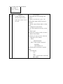
*Adjustment for print start position of ink ribbon
Ribbon Sens. Posi. : Adjustment for print start position of ink ribbon
XX
: Adjustment value
YY
: distance between sensor and print head
0.5mm/digit
Clear key
: decrement value (Min.-9)
Exe key
:
increment value (Max.9)
Appearance of the ribbon (After Printing)
Cyan
Black
Over Coat
ZZ.ZZ mm
Menu of the Adjustment
for print start position of ink ribbon
Ribbon Sens Posi
XX (YY.YYmm)
Adjustment
Value
MENU
CLEAR
Adjust the value to have
ZZ.ZZ ? YY.YY
EXE
increment the value XX and YY.YY
decrement the value XX and YY.YY
*Adjustment of the density of LCD panel
LCD Adjustment
Clear key
: Lighter (min. -3)
Exe key
: Darker (max. 3)
*Adjustment of the angle of Flip Turn unit
Home Angle Adj. : Adjustment of the angle for the horizontal position of Flip Turn
unit
( 0.5 degree/digit)
Clear key
: decrement value (min.-5)
Exe key
: increment value (max. 5)
Note : Adjust the angle correctly. Otherwise it may
cause
card jammed.
*Adjustment of the angle of Flip Turn unit (F/T) in case of card picked up
Pickup Angle Adj. : Adjustment the value to revise the angle of the F/T when card
picked up.
Clear key
: N/A
Exe key
: Start auto adjustment function
This menu is for the adjustment to revise the angle of F/T. Because F/T may rotate
slightly in not intention when picking up a card. In case of any error happens or
F/T rotate beyond the limit while auto adjustment, Auto adjustment will finish as
error. When F/T rotate beyond the limit, check the tension of drive belt for F/T .
(Sensor Check)
This menu to display the sensor outputs and automatic sensor adjustment. Used to
check the condition of the printer when troubleshooting.
*Sensor level display menu
SN 01 02 03 04 05
: Display of status on sensor 01 02 03 04 05
SN 06 07 08 09 10
: Display of status on sensor 06 07 08 09 10
SN 11 12 13 14 15
: Display of status on sensor 11 12 13 14 15
SN 16 17 18
: Display of status on sensor 16 17 18
Clear key
: N/A
Exe key
: N/A
*Display of analog value on the sensor for ribbon detection
SN 10 Analog Disp. : Display of amount of light of sensor for ribbon mark
detection
Clear key
: Decrease the amount of light
Exe key
: Increase the amount of light
SN 10 Analog Disp.
***
*** (***) :
*
Sensor digital out put
Difference from reference level
Analog
value
at
photo
Analog value at LED
Note : Use this menu only when checking the status of the sensor in error
occurred , nevertheless it can be changed out put level.
Note : Since this mode is for just checking , The value adjusted in this mode does
not memorize in the printer.
*Auto adjustment menu for ribbon detection sensor
Auto Adjustment
: Auto Adjustment for ribbon detection sensor
Clear key
:
N/A
Exe key
: Execute auto adjustment
Note : Execute this menu after taking ribbon cartridge out.
Note : Must execute this menu when sensor and/or main board replaced.
Actuator check (Activate the actuators individually )
This menu is for checking the actuators when troubles occur.
Note : Remove the card remained in the printer, otherwise it may cause
trouble.
*Action of transferring Ink ribbon
Ribbon Mtr.(DM1) : Winding up the ink ribbon for limited time
HDRV
: High speed action (100mm/s)(*)
LDRV
: Low speed action (50mm/s)
Clear key
:
Quit action
Exe key
:
Start action
*the speed change to 50mm/s at 50mm before stopping.
Note : Must execute this menu in Ribbon put in the printer.
*Action of head up/down
Headup Mtr.(DM1) : to move the print head to position set.
HOME
: to move the print head to ready position
DOWN
: to move the print head to print position
UP
: to move the print head to the position where ink ribbon can
be changed
Clear key
: stop
Exe key
: start
Note : Do not activate the platen roller at the print head is down position, otherwise
it may cause a print head and/or platen roller damaged.
*Action of supply roller
Pickup Mtr.(PM1)
HDRV
Clear key
Exe key
:
:
activate a supply roller for limited time
High speed (300mm/s)
: stop
: start
Note : Must execute this menu without cards in the card hopper.
*Action of Flip Turn unit (FT) rotation
F.Turn Ang(PM1)
: Rotate FT to set direction
F_HOME
: Forward phase at home position (supplying. HR. normal
ejection)
R_HOME
: Reverse phase at home position (HR. normal ejection)
F_PRINT
:
Forward phase at print position (print. IC encoding)
R_PRINT
:
Reverse phase at print position (print. IC encoding)
F_ENCODE
: Forward phase at encoding position (Mg. encoding, error
ejection)
R_ENCODE
: Reverse phase at encoding position (Mg. encoding, error
e jection)
Clear key
: stop
Exe key
: start
Note : Must execute this menu without cards in the card hopper.
*Action of card transportation rollers at FT
F.Turn Trf(PM1)
: Activate the rollers in FT for limited time
CCW HDRV
:
High speed (CCW, 300mm/s)
CW HDRV
:
High speed (CW, 300mm/s)
Clear key
: stop
Exe key
: start
Note : Must execute this menu without cards in the card hopper.
*Action of card transportation roller at print block
Print Mtr.(PM)
: Activate the rollers at print block in limited time
CCW HDRV
: High speed (CCW, 300mm/s)
CW HDRV
: High speed (CW, 300mm/s)
CCW LDRV
: Low speed (CCW, 200mm/s)
Clear key
: stop
Exe key
: start
Note : Must execute this menu without cards in the card hopper.
*Setting number of cards issued
Print Number
: set the number of times for card transportation test.
Clear key
: decrement number (min. 1)
Exe key
: increment number (max. 100)
*Setting the pattern of card
Select Action
Feeder -> Stack
Feeder -> Reject
Feeder -> Print
Clear key
Exe key
transportation action
:
: Feeder à Normal eject
: Feeder à Error eject
: Feeder à Print block à Normal eject
: N/A
: Selecting action pattern
*Executing of card transportation action
Card Pass Test
: Execute the action which has been set above
Clear key
: N/A
Exe key
: Action start
(Eject Position : setting position of card ejected )
Use this menu for changing the position of card ejected
*Setting position of normal eject
Stack position
Left (default )
: ejecting from left side of the printer
Right
: ejecting from right side of the printer
Clear key
: N/A
Exe key
: select ejecting position
*Setting position of error card eject
Reject position
Left (default )
: ejecting from left side of the printer
Right
: ejecting from right side of the printer
Clear key
: N/A
Exe key
: select ejecting position
*Setting number of card transportation test
Print Number
: Setting number of times for test
Clear key
: decrement number (min. 1)
Exe key
: increment number (max.100)
*Executing of card transportation action
Card Pass Test
: Execute the action which has been set above
Clear key
: N/A
Exe key
: Action start
(User Menu Config.)
This menu is for limitation of showing the menu in User Mode
*Selecting user menu showed
Ribbon Menu Disp. : “Ribbon Type” menu display/not display
Adjust Menu Disp.
: “Image Setup” menu display/not display
Status Menu Disp
: “Printer Status” Menu display/not display
Clear key
: N/A
Exe key
: Change setting (display/not display)
This menu usually use to prevent the settings changed accidentally.
(Encoder Check)
This menu is for checking an encoder .
*Magnetic data writing test
ISO Track 1
: Writing
ISO Track 2
: Writing
ISO Track 3
: Writing
JIS2
: Writing
Clear key
: N/A
Exe key
: Action
to
to
to
to
ISO Track 1
ISO Track 2
ISO Track 3
JIS2 Track
start
To write the data to track of which is set.
When ISO type encoder is set in printer display shows only ISO Track 1 or 2or 3.
******** showed end of data means Total No. of the printer has fed cards.
Writing da ta is as follows
(ISO Track 1)
ISO_TRACK_1_ENCODE_TEST._ARTLAND_COLOR_PRINTER_PR5350_
TOTAL_NO.____********
(ISO Track 2)
12345678901234567890123456789*******
(ISO Track 3)
1234567890123456789012345678901234567890123456789012345678901234567890
12345678901234567890123456********
(IC-R/W Check : To transport a card at IC-R/W position)
*Menu of Action to transport a card
IC-R/W Test
: To check the action of card transported at IC -R/W position
Clear key
: N/A
Exe key
: start action
Once pressing EXE key a card is transported at IC -R/W position and stopped.
Pressing EXE key again the card is ejected from normal exit.
(Heat Roller Check)
To adjust a Heat Roller unit
*Display the total heating time
Heat Total Time : heater total power on time
Clear key
: N/A
Exe key
: N/A
*To adjust transferring position
Position Adj.
: adjusting transferring position (horizontal direction)
unit of adjustment= 0.2mm
Clear key
: decrement value (min.-10)
Exe key
: increment value (max.+10)
Card
-
+
Hologram
*Sensor adjustment
Sensor Adj
: auto adjustment of ribbon detection sensor
Clear key
: N/A
Exe key
: execute auto adjustment
Note : Execute this adjustment after taking ribbon cassette out.
Note : Must execute this menu when replace sensor and main board.
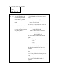
(Error Display)
Error history display
*Error ratio display
Error rate
: displays frequency of error occurred
aa
: number of error lately occurred (max.99)
bbbbb
: number of prints in term of above
Clear key
: N/A
Exe key
: N/A
Error rate
*Error history display
Error Log Disp :
aa
:
bb
:
dd
:
*********
:
Clear key
:
Exe key
:
Error Log Disp
Error : aa (bb)
displays the errors recorded in a printer
error code
detail code
order of error occurred
total count at the error occurred
change stored error (decrement dd late -> past)
change stored error (increment dd past -> late)
dd
Error Log Disp
Count
:
*******
Displays Total count at every 10 errors.
*Number of error occurred display
Error Code rate : Displays number of the error occurred in order
aa
: error code
bb
: detail code
cc
: total number of error occurred
dd
: number of times of the error occurred
ee
: number of times of the error with the detail code occurred
Clear key
: to switch display error code / detail code
Exe key
: to switch display error and/or detail code
Error Code rate
Err. aa (--)
dd/cc
Error Code rate
Add.
aa
ee/dd
(bb)
*Reset the error history
Error Log Reset : Clear error history
Clear key
: error history clear (press with exe key)
Exe key
: error history clear (Press with clear key)
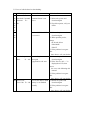
Section 4 Maintenance
4.1 Maintenance List
To keep the optimum performance of the Printer, periodic maintenance operation is
necessary which is described in Section 6, Cleaning and Section 7,
Periodic replacement Parts in the Operation Manual.
This section describes the items which may be required to perform considering the user's
situation, as well as cleaning and replacements.
Section
Maintenance
Tools
Rubber Roller
? Cleaning Roller Every 2,000 frames
Philips screw driver, Soft
Cloth
Alcohol
Replace as required
( 40000 frames )
Symptom: Poor transportation
? Print Roller
Philips screw driver
Cleaning, every 10000 fram es
Soft Cloth.
Alcohol
? Feed Roller
Cleaning, every 10000 frames
?
Cleaning, as required
Symptom: Poor transportation
? Trouble shoot
Other
Pulley Shaft
Soft Cloth.
Alcohol
Apply Grease, as required
Symptom: Noise
Philips screw driver,
Swab
Alcohol
Flat-head screw driver,
Grease ( Molycoat)
4. 2 Method of Maintenance
In this section, the maintenance method is described for the items listed in the
maintenance list. For the following items, read the relative sections of Operation Manual.
Cleaning Cleaning Roller
Replacing Cleaning Roller
Cleaning Print Roller
Cleaning Feed Roller
Cleaning Print Head
Replacing Print Head
Sec. 6
Sec. 7
Sec. 6
Sec. 6
Sec. 6
Sec. 7
4.2.1 Cleaning Rubber Roller
This printer has several sets of rubber rollers to ensure high reliability of card
transportation. However, if the rollers are stained because of use of stained cards or
cards coated with special materials, transport error may occur due to reduced
transportation power. Though periodic cleaning of rollers may be performed by users
with a certain level of experience, the following intensive cleaning should be done if
such transportation error occurs.
? Transport Rollers in Flip Turn Module
? Open Top Cover and rotate Turn Module so that the rollers
come to the position where the cleaning can be done easily.
? This operation is done with the green knob in the flip turn module.
?
Press a soft cloth with alcohol to the rollers and rotate them.
? This operation is done by rotating Green handle located at inside of
side plate.
? Transport Rollers
? Open the left cover and insert a soft cloth with alcohol and press against rollers
and rotate them.
? This operation is done with Cleaning Knob located on the Front
Access Panel.
4.2.2 Applying grease to Pulley Shafts etc.
Plastic rollers used in this Printer is made of self-lubricative plastics.
On the shafts of rollers which are loaded with torque and has friction with shaft, grease
is applied at the factory. Although further greasing in not required for normal usage,
grease should be applied in case following parts are replaced for some reason or
abnormal noise is detected.
Part No.
Name
Section 5 Replacement and Adjustment
5.1 Replacing Main Board (PBA-MAIN)
Step 1: Remove R-COVER
Step 2: Loosen two screws on the lower edge and remove two screws on the upper
edge of MAIN-BOARD-PLT and remove a screw to fix the ground cable.
Then, lean the board backward.
Step 3: Disconnect all harnesses from the board. (CN1 - CN15)
Step 4: Remove Main Board. ( 7 screws )
Step 5: Fix new Main Board onto the Printer (7 screws) and connect all harnesses.
Step 6: Make sure that the SW1 is set as NORMAL MODE.
Step 7: Raise the MAIN-BOARD-PLT and fix with screws. (4 screws)
Step 8: Attach R-COVER.
Step 9: Turn ON the power and make downloading
Download the resistance data of print head first.
Then,:
? Adjustment of Print Position, Print Uniformity, Print Density.
? Adjustment of Sensor levels.
? Settings to be done in User Mode ( Buzzer ON/OFF etc.)
Note: Turn OFF all Systems connected each other including PC when performing this
operation.
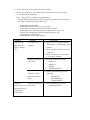
5.2 Adjustment after Main Board replaced.
? In the memory on the Main Board, the adjustment values for the printing operation are
stored. Therefore, when replacing the main board, the adjustment in the following steps
are necessary. It is advisable to memorize these adjustment values before beginning the
replacement work so that the values can be used for the new board.
? If there is a difference in the print quality between before and after there placement of
the thermal head, adjust as following.
? For the details of the operation panel, please refer to Section 3, Operation Panel.
? Items to be adjusted in the Serviceman Mode
Adjustment Items
Print position
Print uniformity
Print density (Color)
Print density ( BK)
Sensor (SN10 ) level
?
?
X
Main Board
Replacement
?
?
?
?
?
Thermal Head
Replacement
?
?
?
?
X
: Necessary
: Depending on the print result
: Unnecessary
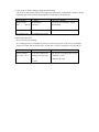
? Items to be set in the User Mode ( Main Board Replacement only)
Setting Items
Ribbon Type
Setting
Setting the ribbon type to be used
Color Adjustment
Setting the color for color printing
Buzzer
Setting buzzer for the occurrence of error
Memory Mode
Setting the image memory
SCSI ID
Setting SCSI ID number
Parity Set
Setting the parity check of SCSI communication
Encode Type (Note)
Setting the type of magnetic encoding
Encode First (Note)
Setting priority of encoding or printing
Encode Mode (Note)
EXE Key Print
Setting the card insertion direction to the encoder
Print Retry
Setting automatic retry at the error recovery
Parallel Print
Setting parallel processing
Card Eject Face
Setting card side when ejected
Print Area
Setting maximum print area
Setting the printing by EXE key
Note: Setting of the encoder related items can only be made for the device
with the built-in encoder.
5.2.1 Adjusting the Print Position
When main board is replaced, check and adjust the print position in the following
procedure.
Step 1.
Print Test Pattern H in the "Position Adjustment" menu of Service Mode.
Step 2. Adjust Horizontal and Vertical values so that dimensions h and v
(distance from the edge of card) become 0.5 +/-0.2mm.
Step 3. Print the Test Pattern H again and confirm the h and v dimensions.
Repeat the above if necessary.
Note 1: If h, v, is smaller than 0.5mm, increase the setting value.
If h, v, is larger than 0.5mm, decrease the setting value.
Note 2: Setting value can be calculated in the following formula.
H'= H + (0.5-h)/12
H' : New setting value ( Horizontal )
H : Current value
( " "
h : measured value ( mm )
)
V' can be obtained in the same formula.
Note 3:
Start adjustment with the current value (value before replacing
Thermal Head) retained.
Test Pattern for print position adjustment
<mm - dot conversion>
The resolution of the Thermal Head is 300 dpi. Therefore, adjus tment should be
done in this unit. Convert the measured value into the dot number using the table
below.
New Setting Value = Current Value + (0.5 - Distance from card edge)
Convert by the following table.
If the distance is (-), dot should also be (-).
d o t
0
1
m m
0.00
0.08
d o t
26
27
m m
2.20
2.29
2
3
0.17
0.25
28
29
2.37
2.46
4
5
6
0.34
0.42
0.51
30
31
32
2.54
2.62
2.71
7
8
9
10
0.59
0.68
0.76
0.85
33
34
35
36
2.79
2.88
2.96
3.05
11
12
0.93
1.02
37
38
3.13
3.22
13
1.10
39
3.30
14
15
1.19
1.27
40
41
3.39
3.47
16
17
18
1.35
1.44
1.52
42
43
44
3.56
3.64
3.73
19
20
21
22
1.61
1.69
1.78
1.86
45
46
47
48
3.81
3.89
3.98
4.06
23
24
1.95
2.03
49
50
4.15
4.23
25
2.12
5.2.2 Adjustment of Print Uniformity
When the main board is replaced, check and adjust the print uniformity in the following
procedure after adjusting the print position.
Step 1: Print Test Pattern H in "Uniformity Adjustment" menu of "Service Mode".
Step 2: Compare print density of the following three positions A, B, C, and decrease
the densities of two positions to the same as the least dense position.
Step 3: Print Test Pattern H again and check the density of the three positions.
Adjust again if necessary.
Note 1: Use density meter to compare the densities. If the instrument is not
available, check visually.
Note 2: Three positions A, B, C, correspond to the positions shown on the Operation
Panel as following:
A:
Upper
B:
Center
C:
Lower
Note 3: Start adjustment with the current value (value before replacing Thermal
Head) retained.
uniformity
Test Pattern for
adjustment
5.2.3 Adjustment of Print Density
When the main board is replaced, check and adjust the print density in the following
procedure after adjusting print position and print uniformity.
? Adjustment of Image and Protective Layer
Step 1: Print Test Pattern J in "OD Adjustment" menu of "Service Mode".
Step 2: Change "Color" Setting Value so that there is no color drop off and the
average density of Positions A, B, C, becomes within 1.65 +/-0.05.
Step 3: If the starting portion of Protective Layer is not printed, increase value of
"Clear". ( Caution: Do not set too large value because it may cause a trouble.)
Step 4: Print Test Pattern J again to check the densities of A, B, C. Adjust again if
necessary.
Note 1: Use density meter to compare the density, If instrument is not available, use
sample card and compare visually.
Note 2: The larger the "Color" value, the higher the density becomes.
Note 3: Start adjustment with the current value (value before replacing Thermal
Head) retained.
Note 4: Start adjustment with remaining the value that is set before changing print
head
Test pattern for OD adjustment
? Adjustment of BK
Step 1: Print Test Pattern E in "OD Adjustment" menu of "Service Mode".
Step 2: If there is a drop off in the image, increase the setting value. Conversely, if
the image is too thick and lines touches each other, decrease the value.
Step 3: Print Test Pattern E again and check the print condition. Adjust again if
necessary.
Note 1:
Start adjustment with the current value (value before replacing Thermal
Head) retained.
Note 2: As to the operation of the Operation Panel, refer to Section 3
"Operation of Operation Panel".
Test Pattern for resin BK adjustment
5.2.4 Adjustment of Sensor Level
Adjustable sensors of the Printer are factory adjusted at the time of shipment.
Readjustment is necessary in the following case:
?
?
?
?
Sensor is replaced. (light source, receiver)
Mechanically changed affecting the light axis.
Main Board (P BA-MAIN) is replaced.
Ribbon related error occurs frequently.
If the sensor output voltage is below the specified value in spite of the adjustment
according to correct procedure, repair the defective parts as instructed in paragraph 3.
Note : Adjust the sensor output level at where the external light will not affect.
When measuring the output voltage of the sensor with volt meter, use the meter
at 0.1V range.
1) Automatic Adjustment of Sensors
Step 1:
With the power OFF, visually confirm that there is no card in the
Printer.
Step 2: Open Ribbon Cover and pull out the Ribbon Cartridge.
Set the Ribbon Cartridge again in the position so that Yellow Part of the
Ribbon comes to block the light to SN10 and close the Ribbon Cover.
Step 3:
Turn ON the power and execute "Sensor Auto Adjustment" menu in
"Service Mode".
Step 4:
Finish "Service Mode".
Note:
Refer to Sec. 3 "Operation of Operation Panel".
2) Checking Sensor Output Voltage
Following is the standard voltage reading of Test Pins on the Main Board for
checking the sensor voltage with tester.
?
SN10( Detection of mark on the Ribbon )
Test Pin: TP88(SN10PT)
Lighted:
1.0V or less ( Yellow detection )
Blocked:
3.0V or more ( Bk detection )
Note: Above voltage is between TP88 and TP65(SGND) on the Main Board.
Location of Test pins
3) Countermeasure for the Abnormal Sensor Output
If the sensor output as described in 2) is not obtained, locate the defective part and
repair in the following procedure.
Possible Defect
Defective connection of
harness and Printed
Printed Circuit Board.
Check and Repair
Check contcts of all connectors which connects
the boards with light sources and sensors to
the Main Board.
Check the contact of each harness with circuit
tester following the circuit diagram and if
defective connection is found, replace the
harness.
Defective mounting of
sensor.
Check mounting of the light sources and
sensors. If incorrect mounting angle of
sensor or loose screw is found, correct
the mounting.
Conf irm that the light emitting face and the
receiving face of the sensors are facing
directly and there is nothing in between to
block the light.
Defective sensor.
Replace the sensor (light emitter and receiver )
and confirm normal operation.
Defectiv e Main Circuit
Board.
Replace the Main Circuit Board (PBA-MAIN)
and confirm normal operation.
Note:
Turn OFF the power when checking connection of harness and replacing parts.
5.3 Adjusting density of LCD Display
Density of LCD Display on the Operation Panel Board (PBA-OPEPANE) is adjusted
to the optimum when shipping from factory. However, it can be adjusted by the user in
the following procedure.
Step 1: Turn ON the power and get the LCD Adjustment in Service Mode.
Step 2:
To make the density higher, press EXE key
To make the density higher, press EXE key
5.4 Adjustment for Card Thickness
? Adjustment of Gap of Separation Gate
Step 1. Open cover of Card Supply Box, loosen 2 screws (M3 x 8) fixing the Gate a nd
lift the Gate.
Step 2. Insert a flat plate 'having about 1.5 times of thickness of the card' beneath the
middle of the gate and press down the Gate and tighten the screws.
Step 3. Remove the plate.
Loosen two screws
Section 6 Troubleshooting
This paragraph deals with the causes and countermeasures for various troubles which
may occur with the printer system.
6.1 Troubleshooting with the display on the LCD.
When a trouble is detected, the error indication LED on the operation panel is
turned ON and the type of the trouble is shown on the LCD. In this section, the cause and the
method of recovery are explained based on the display on the LCD.
? The type of the error is indicated with the two digit of error code (Er) and two digit of
details code(Ad).
On the LCD panel, it is shown with error message (16 digits x 2 lines: corresponding to the
error code ) and four digit numbers ( 2 digits :Er and 2digits:Ad ) on the lower right corner.
example
In this case
Error Code (Er)
: 12h
Details Code (Ad ) : 01h
The details code may be indicated with the wild card (**) in this paragraph.
Front Cover is
Open
12-01
? User operates the error recovery steps based on the error message on the LCD panel. Most
of the errors can be recovered by the user. However, in case of unrecoverable error or
frequent errors, the service person must be called.
? When the re is a service person call from users, please ask to inform detailed symptoms, error
message and details code.
6.1.1 Display on the LCD and method of recovery
(1) Display of normal status
The following displays on the LCD are normal status of the printer.
To distinguish from the error, the error indication LED is not lit and the details
code is not displayed.
LCD Display
Ready to print
Status
The printer is at the waiting status (normal status ).
It is possible to transfer the data from the host computer and
print.
Ready to print.
-Head upsidePlease wait ...
Initializing
Please wait ...
Now printing
Please wait ...
HeatRoll Warm
Up
Ready to
Down load
The print head is lifted and the ribbon cassette can be removed.
It is possible to transfer the data from the host computer and
print.
Printer is being initialized.
Printer is processing the printing job. Depending on the setting
of the memory mode, the data transfer is possible in this status.
Optional heat roller unit is being warmed up.
This indicates that the booting as safety mode because the main
program is damaged .
Download the main program.
Please read paragraph 7 for the downloading.
HOST -> Fl
Memory
Loading
This indicates that now loading.
.....wait
(2) Messages to prompt manual recovery from the error
The following messages shows the steps of manual operation to recover.
When the [CLEAR] key is pressed after the error, the printer does the recovery
operation if the conditions for recovery are met. If not, one of the following messages
will be shown. There is no details code. ( This shows the condition for recovery
only and does not indicate occurrence of any error.)
LCD Display
Check Ink
Ribbon
Card Empty
Front Cover is
Open
Top cover is
open
Status
CLEAR] key is
Take out the ribbon cassette and
pressed while Ribbon check the status of the ribbon. Then,
Empty or Ribbon Take close the Front Access Cover and
press [CLEAR ] key.
Up error.
[CLEAR ]key is
pressed
while there is no card.
CLEAR]key is pressed
while the Front Cover
is
open.
[CLEAR ]key is
pressed
while the Front Cover
is
open.
[CLEAR ]key is
Card Jam
Remove the card pressed
while a card is
Resist Data is
not loaded
Recovery Method
remaining
inside of a machine
[CLEAR ]key is
pressed
while the Data is not
Set the cards in the card hopper
and press [CLEAR]key.
Close the Front Access Cover and
press [CLEAR ] key.
Close the Side Access Cover and Top
Cover
Then press [CLEAR ] key.
Turn power off and remove the card
manually. See the operation manual for
how to remove the card.
Turn power on .
Download the resistance data of which
the
ser.# is matched to the ser.# of the print
installed
head. See the operation manual Section 7
for downloading.
Can not Recover
CLEAR] key is
Turn OFF and ON the power, or
Please Reset
pressed
while there is an
unrecoverable error.
execute RESET on the operation
panel.
(3) Error message display in the normal usage of the printer. These are the errors which occur
while the printer is in normal use. They are easily recoverable by the users. However, the errors
may be erroneously detected by the sensor defectives. In such case, the checking and repair by the
service person is necessary.
LCD Display
Card Empty
1301
Ribbon Empty
20**
Front Cover is
Open 1001
Top Cover is
Open
1101
Ribbon Type
Incorrect 22 **
Status
Recovery Method
Card is empty.
Set the cards in the card hopper
and press [CLEAR ] key.
Printing Ribbon is
finished.
Set new ribbon in the printing
block and press [CLEAR ] key.
Front Access Cover is
open.
Check that the Front Access
Cover is positively closed and
press [CLEAR ] key.
Front Access Cover is
open.
Check that the Front Access
Cover is positively closed and
press [CLEAR ] key.
The type of ribbon does Check whether the ribbon type is
not
same as the printer setting. if it is
match the printer setting. different, change the setting of
the operation panel.
(4) Card jam related Error messages
Card jam errors occur when the card is not transported in the printer system as the
sequence. The basic recovery steps for the card jam errors are described below.
The card jam errors may be caused by the cards being used. Check if there is any
problem on the card itself such as the specification (thickness, size, etc. ), bend,
surface finish ( anti-static treatment, special finish, etc. ).
LCD Display
Card Jam. Feeder
Area**-**
Status
Card is not fed normally
from the card feeder.
Card Jam. Feeder
Area42-**
Recovery Method
Check w hether the cards are set
correctly in the card feeder and
press [CLEAR ] key.
A card remains at SN02
and can not pass to F/T
unit
Card Jam. F. Turn Card transportation
Area-**-**
error in the flip turn
block.
Take the card out by hands
Card Jam. F. Turn A card remains at SN03
Remove-- 47-**
and can not pass to F/T
unit
Take the card out by hands
Card Jam. F. Turn A card is lost between
Lost-**-**
F/T
and an unit around the
F/T
Take the card out by hands
Card Jam. Print
Area-**-**
Card transportation
error in the print block.
Press [CLEAR ] key.
Card transportation
error in the Encoder
Press [CLEAR ] key. If impossible to
Card Jam. Encode
Area-**-**
Unit.
Press [CLEAR ] key. If impossible
to recover, checking and repair by
service person is necessary.
If impossible to recover, check
and repair by the service person
is necessary.
recover, check and repair by the
service person is necessary.
(5) Error messages of the internal troubles of the printer.
The following is the error messages of the internal troubles of the printer system.
Most of those troubles needs the check and repair by the service person.
LCD Display
Service Man Call
error Code **-**
Status
There is an unrecoverable
error in the printer.
Recovery Method
Turn OFF and ON the power or
execute RESET. If the error repeats,
check and repair by the service
person
is necessary.
6. 1. 2 Checking and repairing of the hardware related troubles.
Please check and repair in the following steps when the errors are not recovered by the users.
< Note > Read the following without fail before troubleshooting.
? There are Error Message, Error Code, and Details Code for each errors.
· To find diagnosis form the LCD Display, use the combination of Error Message
Error Code (Er) and Details Code (Ad).
· Use the combination of Error Code and Details Code for checking the contents of
the error log.
? Do not forget to turn OFF the power switch and disconnect the power cord before
performing the following operation.
· Replacing the thermal head.
· Removing the front or back cover of the printer.
· Checking connection of the harness etc.
· Replacing the parts of PCB, sensor, motor, etc.
· Installing or dismounting the Encoder Unit to the printer.
· Connecting the optional units.
· Removing the cover of the optional units.
*To use the sensor check mode to check the sensor operation with the cover removed,
please
be careful not to touch the PCB. It may cause a trouble.
As it is dangerous, please carefully operate the operation panel not to move into
other mode than the sensor check mode.
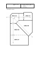
? Card Jam Errors are detected by the sensors located along the card path, and
classified in two categories according to the cause.
· Un-arrival Jam: In the card transportation, the card is not detected at a
specified position after a specified time.
· Staying Jam: In the card transportation, the card is staying at the position
where it should not stop at. ( Undesired sensor condition ).
? "Area ----" in a message of card jam means detail of where card is stuck.
See Area map in section 6.3.
? If the error relating to the adjustable sensors repeats, the incorrect setting of the sensor
is doubted. Readjust the sensor sensitivities following the instruction in the paragraph 3.
· SN11 Ink ribbon end sensor.
? When checking the various actuators, please check that no card is remaining in
the printer. If the independent checking operation is done while the card is
remaining, it may cause other trouble.
? Please follow the steps described in the paragraph 4, for cleaning of the rubber rollers.
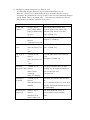
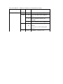
List of the hardware error related error messages
Error code 10h-2Fh
cover open / card empty / related to ribbon
Error Message
Er. Code
Ad. Code
Front Cover is Open
Top Cover is Open
10
11
01
01
Front cover is open
Top cover is open
Card Empty.
13
01
Hopper is empty
Ribbon Empty.
20
01
03,04
06
Ribbon Wind up miss.
21
03
22
23
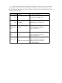
Error code 30h-3Fh
Error Message
Service Call Error
Code
End mark is detected
Abnormal winding up (Initializing)
End mark is detected (Initializing)
01
Abnormal velocity is detected on
Ribbon transfer roller
Abnormal pulse is detected on ribbon
supplying spool
length is shorter on a color panel
02
03
length is longer on color panel
failure on detecting the mark on panel
04
to panel
could not detect a unique mark
05
Abnormal cycle of unique mar k
**
Ribbon transportation time out
04
Ribbon Type
Incorrect.
Description
Relation to hardware on print block (F/T rotation, head up down)
Er. Code Ad. Code
Description
30
**
31
32
02-04
**
F/T Stops at abnormal position
Time out error on action of head
01,02
UP/down
Ribbon sensor adjustment range out
03
36
37
38
Time out error on F/T rotation
Ribbon sensor adjustment time out
04,05
Ribbon sensor adjustment (fine) range
06
Ribbon sensor adjustment (fine) time
01
Head cooling fan error
02
Power supply cooling fan error
01
T hermal sensor for head error
02
T hermal sensor for power supply error
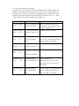
Error Message
Ad. Code
Description
Er.Code
Service Call Error
Code
Resist data is not
39
01
02
DSP information is not applied
DSP data format error
3A
01
DSP communication (sending) enable
time out
**
DSP command sequence error
3B
01
DSP c ommunication (receiving) enable
time
Out
3C
01
3E
01
DSP communication DMA control
error
Resist data for print head is not applied
3F
01
Loaded
Resist Data Code error
Error code 40h-5Fh
Relation to card Jam in card supply, F/T and print block
Error Message
Card JAM.Feeder
Area01
Error on format of Resist data for print
head
Ad. Code
Er.Code
40
41
Description
**
**
supply block card JAM (Area 01)
supply block card JAM (Area 02)
Card JAM.Feeder
Area01
Card JAM.Feeder
Remove
42
43
44
45
**
**
**
**
supply block card JAM (can not
eject)
F/T block card JAM (Area 02)
F/T block card JAM (Area 03)
Card JAM.F.Turn
Area02
Card JAM.F.Turn
Area03
Car d JAM.F.Turn
Area04
Card JAM.F.Turn
Area08
Card JAM.F.Turn
Remove
Card JAM.F.Turn Lost
46
47
48
49
50
51
52
53
54
**
**
**
**
**
**
**
**
**
F/T block card JAM (Area 04)
F/T block card JAM (Area 08)
F/T block card JAM (can not eject)
Lost a card in F/T (when going in)
Lost a card in F/T (when going out)
Print block card JAM (Area 04)
Print block card JAM (Area 05)
Print block card JAM (Area 06)
Print block card JAM (Area 07)
Print block card JAM (can not going
out)
Card JAM.F.Turn Lost
Card JAM Print
Area04
Card JAM Print
Area05
Card JAM Print
Area06
Card JAM Print
Area07
Card JAM Print
Remove
Error code 60h-6Fh
Relation to firmware control error
Error Message
Ad. Code
Description
Er.Code
Service Call Error
Code
Error code 70h-78h
Error Message
Service Call Error
Code
60
**
61
**
62
**
supply block operation control time out
error
F.Turn block operation control time out
error
print block operation control time out
6A
6B
**
**
supply block command sequence error
F.Turn block command sequence error
6C
**
print block command sequence error
6D
**
En unit command sequence error
6E
6F
**
2*
H/R unit command sequence error
print block sequence error
4*
H/R unit sequence error
Relation to Magnetic encoder unit
Ad. Code
Description
Er.Code
70
01-03
0F
71
10-16
Data sending error with Printer -En unit
Data receiving error with Printer-En unit
Sequence error with Printer-En unit
72
01
En unit format error
73
**
En unit hard ware error
Encoder Write error
74
**
En unit writing error
Encoder Read error
75
**
En unit reading error
Encoder Data error
76
20
En unit incorrect data writing error
77
**
En unit card JAM (Area 08)
78
**
En unit card JAM (Area 09)
Card JAM Encode
Area08
Card JAM Encode
Area09
Error code 79h-7Fh
Error Message
Relation to Magnetic encoder unit
Ad. Code
Description
Er.Code
IC R/W Control Error
7E
01
IC processing error
Error code B0h-CFh
Relation to hardware on communication/ memory
Error Message
Ad. Code
Description
Er.Code
Encoder Data Error
BC
C0
01-04
01
1*
C1
2*
01
02
C3
01-06
Error with specifying on IF Board
Error with DMA control (DRAM->
CPU)
Error with DMA control (CPU >DRAM)
Error with DMA control (DRAM clear)
T ime out error when clearing flash
memory
T ime out error when writing flash
memory
EEPROM read/write error
(1) Front Cover Open
Front Cover is
Open
ErAd
Er Ad
10 01
Symptom
Front Access Cover
is left open
If it becomes error
despite
the cover is closed, see
the
Check/Repair section.
Check/Repair
(1) Check the reaction of SN13 to detect
open/close of the Front Cover by using
Sensor Check Mode.
(2 ) If the sensor does not react normally,
check connection and electric contact
of the harness.
· ASM-I/F-SW
(3) If the harness connection is not
normal, replace the following:
· SN13
· PBA-MAIN
(2) Top Cover Open
Top Cover is
Open
Er Ad
11
01
Er-Ad
Symptom
Top Cover is left open
If it becomes error
despite
the cover is closed, see
the
Check/Repair section.
Check/Repair
(1) Close the Front cover and check the
reaction
of SN14 to detect
open/close of the Top Cover by using
Sensor Check Mode.
(2 ) If the sensor does not react normally,
check connection and electric contact
of the harness.
· ASM-I/F-SW
(3) If the harness connection is not
normal, replace the following:
· SN14
· PBA-MAIN
(3) Card Empty
Card Empty
Er-Ad
Er Ad
13
Symptom
01 Card is not set in the
supply block.
If it becomes error despite
the cards are set, see the
Check/Repair section.
Check/Repair
(1) Check the reaction of SN1 by using
Sensor Check Mode.
(2) If the sensor does not react normally,
check the connection and electric contact
of
the harness.
· ASM-SENSOR-A
(3) If the harness connection is normal,
replace the following:
· SN-1
· PBA-MAIN
(4) Ribbon Empty
Ribbon Empty
**
Er Ad
Symptom
Check/Repair
(1)Adjust
the
sensor
SN10in the Sensor Check
20 01 Ribbon Empty mark has
Mode. If impossible to adjust, check the
06 been
connection and electric contact of the harness.
detected. If it becomes error
· ASM-SENSOR-B
despite the ribbon is set
· ASM-LD RELAY2
(2)If
the
harness connection is normal, replace
correctly and it has not
the
following:
reached at the empty mark,
· SN10 (LD,PT)
see the Check/Repair
· PBA-MAIN
section.
03 Velocity of winding ribbon (1) Check the reaction of SN8.
by using Sensor Check Mode.
is faster than it set.
If the sensor does not work correctly, go
(2b) or
If a ribbon is set correctly
(3b) mentioned below
and not to reach to end
(2a) The sensor works correctly, check the
connection and electric contact of the
mark yet,
harness
See Check/Repair section.
for DM1
ASM-MOTOR
(3a) If the harness connection is normal,
replace the following
l Ribbon cassette
l DM1
l PBA-MAIN
(2b)Check the connection and electric contact
of the harness for SN8
ASM-SENSOR-C
(3b)If the harness connection is normal,
replace the following
l SN8
l PBA-MAIN
(1)
Check
the reaction of SN18.
04 Feeder side of ribbon does
by
using
Sensor Check Mode.
not
(2) If the harness connection for SN18 is
rotate.
abnormal , replace the following
f a ribbon is set correctly
* ASM-SENSOR-C
and not to reach to end
(3) If the harness connection for SN18 is
normal,
mark yet,
replace the following
See Check/Repair section.
l Ribbon cassette
l SN18
l PBA-MAIN
(5) Ribbon Take Up Error
Ribbon Wind up
miss
**
Er
21
Ad
Symptom
03 Take up speed of the ink
Check/Repair
(1 )Check reaction of sensors SN8 in
ribbon is too slow.
Sensor Check Mode.
Check whether the ribbon is
If the sensors do not react normally, go to
(*b)
set correctly.
This error occurs when the (2a)If there is no problem with the sensor, the
ribbon adheres on the card.
motor (DM1) is questionable. Check the
Check if improper card is
connection and electric contact of the
used, such as double
harness of DM1.
· ASM-MOTOR
printing
Some materials of the c ard (3a)If the harness connection is normal,
may cause this trouble.
If there is no problem as
above,
see the Check/Repair
section.
replace
the following:
· Ribbon Cassette
· DM1
· PBA-MAIN
(2b)Check connection and electrical contact of
harnesses of SN18
ASM-SENSOR-C
(3b)If the harness connection is normal,
replace
the following:
· SN18
· PBA-MAIN
04 Take up speed of the ribbon (1) Check reaction of sensors SN8 in
is too fast. Check if the
Sensor Check Mode.
(2)Check connection and electrical contact of
ribbon is set correctly.
If this error occur in spite
of
R ibbon is set correctly and
not
come end.
If there is no problem as
above, see the
Check/Repair section.
(6) Incorrect Setting of the Ribbon Type
harnesses of SN18
ASM-SENSOR-C
(3)If the harness connection is normal, replace
the following:
· Ribbon Cassette
· SN18
· PBA-MAIN
Ribbon Type
Incorrect
Er Ad
22
22
**
Symptom
Check/Repair
01 Distance between the edges (1)Clean the ribbon transport rollers.
02 of the ribbon does not meet (2)Ribbon Cassette seems to be wrong.
as it is supposed to be.
Replace the following:
· Ribbon Cassette
03 Impossible to detect
Ribbon Edge.
(1)Check whether there is a damage on the
ribbon.
(2)Adjust the sensor SN10 in the Sensor
Check Mode. If impossible to adjust, check the
connection and electric contact of the harness.
· ASM-SENSOR-B
· ASM-LD RELAY2
(3 ) If the connection of the harness is normal,
replace the following:
· SN10(LD/PT)
· PBA-MAIN
04 Impossible to detect
Unique mark
(1) Check whether there is a damage on the
ribbon.
If this error occur in spite
of
R ibbon is set correctly, see
(2) Adjust the sensor SN10 in the Sensor
the Check/Repair section.
· ASM-SENSOR-B
· ASM-LD RELAY2
(3) If the connection of the harness is normal,
Check Mode. If impossible to adjust, check the
connection and electric contact of the harness.
replace the following:
· SN10(LD/PT)
· PBA-MAIN
05 Distance between each
unique mark of the ribbon
does not meet as it is
supposed to be.
If this error occur in spite
of
R ibbon is set correctly, see
the Check/Repair section.
(1)Check whether there is a damage on the
ribbon.
(2) Adjust the sensor SN10 in the Sensor
Check Mode. If impossible to adjust, check the
connection and electric contact of the harness.
· ASM-SENSOR-B
· ASM-LD RELAY2
(3) If the connection of the harness is normal,
replace the following:
· SN10(LD/PT)
· PBA-MAIN
(7)
Hardware damage
Service Man Call
Error Code **
Er Ad
30
**
31
02
03
04
Er
Ad
Symptom
Check/Repair
(1)
Open
the top cover and check if there is
No signal fed back from
an obstacle such as a card.
the
(2) If there is a card protruding from the flip
sensor 6, when F.Turn unit
turn unit and hitting the sensor etc.,
rotating.
card transport accuracy defect is
doubted. Remove the staying card and
clean the transport rollers in the flip
turn unit.
(3) If there is no obstacle, check the out put
on SN6 in Sensor Check Mode
When abnormal situation is found, go
(*b)
(4a) PM1 is doubted. Check the motion of
PM1 in the Actuator Check Mode.
(5a) If PM1 does not work, check connection
and electrical contact of the harness.
· ASM-MOTOR
(6a) If the harness connection is normal,
replace the following:
· PM1
· PBA-MAIN
(4b) Turn angle sensors are doubted.
Check connection and electrical contact
of the harness.
· ASM-SENSOR-A
(5b) If the harness connection is normal,
replace the following:
· SN6
· PBA-MAIN
(1 ) Open the top cover and check if there is
F.Turn unit stops the
position where is before
an obstacle such as a card.
target position
(2) If there is a card protruding from the flip
F.Turn unit stops the
turn unit and hitting the sensor etc.,
position where is after
card transport accuracy defect is
target position
doubted. Remove the staying card and
F.Turn unit stops the
clean the transport rollers in the flip
position where is not in
turn unit.
detection range.
(3) If there is no obstacle, check the out put
on SN6 in Sensor Check Mode
When abnormal situation is found, go
(*b)
Symptom
Check/Repair
(4a) Re-adjust the stop position of F.Turn unit.
*Home angle Adj.
*Pickup angle Adj.
(4b) Turn angle sensor (SN7) is doubted.
Check connection and electrical contact
of the harness.
· ASM-SENSOR-A
(5b) If the harness connection is normal,
replace the following:
· SN7
· PBA-MAIN
32
**
Head is not detected in the (1) Check the motion of DM3 in the Actuator
specified position within
Check Mode. If the motor works
normally, go to (2b).
the
(2a) DM1 is doubted. Check connection
specified time when the
head
lifting motor is activated.
and electrical contact of the harness.
· ASM-MOTOR
(3a) If the harness connection is normal,
replace the following:
· DM1
· PBA-MAIN
(2b) The head position sensors seem to have
problem. (SN11, SN12)
Check connection and electrical contact
of the harnesses.
· ASM-SENSOR-C
(3b) If the harness connection is normal,
replace the following:
· SN11
· SN12
· PBA-MAIN
36
01
|
Impossible to adjust
ribbon leading edge
06 sensor
properly.
(1) Check connection and electrical contact
of the harnesses.
· ASM-SENSOR-B
· ASM-LD RELAY 2
(2) If the harness connection is normal,
replace the following:
· SN10 (LD/PT)
· PBA-MAIN
Er Ad
Symptom
Check/Repair
37
38
01
Head cooling fan trouble
has
been detected.
02
Power supply unit cooling
fan
trouble has been detected.
01
Head temperature is out
of range.
(1) Check connection and electrical contact
of the harnesses.
· ASM-MOTOR
(2) If the harness connection is normal,
replace the following:
· HFAN
· PBA-MAIN
(1) Check connection and electrical contact
of the harnesses.
· ASM-MOTOR
(2) If the harness connection is normal,
replace the following:
· DFAN
· PBA-MAIN
(1) Check connection and electric al
contact of the harness of the thermal
head.
ASM-HEAD
(2) If the harness connection is normal,
02
Temperature around the
main board is out of range
replace the following.
Thermal Head
PBA-MAIN
(1) Make sure of ambient temperature is in
the
range of what is mentioned in user
manual
(2) If the temperature is in that range, replace
39
3A
3B
3C
01
The information of DSP is
not registered
02
The information of DSP is
broken.
01 A communication between
** DSP and CPU has been
finished
Abnormally.
the following.
PBA-MAIN
(1) Download the main program
(2) If this symptom repeats, replace following
PBA-MAIN
(8) Relation to Print Block ( resist data)
Resist Data is
Not Loaded Er -Ad
Ad
Symptom
Resist Data
Code Error ErAd
Check/Repair
Er
3E
3F
01 The information of a resister (1) Download the data of which serial
is not registered
number is as same as Thermal head.
(2) If this symptom repeats, replace
following
01 T he information of a resister
PBA-MAIN
is broken.
(9) Card Jam in the Card Feed Block
Card JAM. Feeder
Area 01
Er Ad
Er
Ad
**
40
Symptom
Card does not arrive at
SN2 while feeding.
Check/Repair
(1)Check that the card is not arrived at the
SN2.
If it has arrived or passed through, go to
(2b).
(2a)Check the motion of PM1 in the
Actuator
Check Mode. If the motion is normal, clean
the
feed rollers in the card feeding block and
adjust
the separation gate.
(3a)If it does not work normally, check the
connection of harness.
· ASM-MOTOR
(4a)If the harness connection is normal,
replace
the following:
· PM1
· PBA-MAIN
(2b)Check the reaction of SN2 in the
Sensor Check Mode.
(3b)If SN2 does not react, check the
connection of the harness.
· ASM-SENSOR-B
(4b )If the harness connection is normal,
replace
the following:
· SN2
·
PBA-MAIN
(10) Card Jam in the Card Feed Block
Card JAM. Feeder
Area 02 Er - Ad
Er
41
Ad
**
Symptom
Check/Repair
A card jam has occurred (1)Check that the card is staying at the SN2.
If there is not the card , go to (2b).
at
SN2.
The card has reached at Cleaning Roller,
there is possibility of transporting motor
failure on Flip Turn Unit . Then see the Error
Code 43 part.
(2a)Check the motion of PM1 in the Actuator
Check Mode. If the motion is normal, clean
the feed rollers in the card feeding block and
adjust the separation gate.
(3a)If it does not work normally, check the
connection of harness.
· ASM-MOTOR (CN118)
(4a)If the harness connection is normal, replace
the following:
· PM1
· PBA-MAIN
(2b)Check the reaction of SN2 in the
Sensor Check Mode.
(3b)If SN2 does not react, check the
connection of the harness.
· ASM-SENSOR-B
(4b)If the harness connection is normal, replace
the following:
· SN2
· PBA-MAIN
(11) Card Jam in the Card Feed Block
Card JAM. Feeder
Remove Er - Ad
Ad
Symptom
Check/Repair
Er
**
42
A card is detected at SN2 in (1)Check that the card is staying at the SN2.
If there is not the card , go to (2b).
when F.Turn unit is not
ready to receive the card.
(2a) Adjust the separation gate.
(2b) Check the reaction of SN2 in the
Sensor Check Mode.
(3a) If SN2 does not react, check the
connection of the harness.
· ASM-SENSOR-B
(3b) If the harness connection is normal,
replace
the following:
· SN2
· PBA-MAIN
(12) Card Jam in the Flip Turn Block
Card JAM F.Turn
Area 02
Er Ad
Er
43
Ad
**
Symptom
Card jam error in the
Area02(SN2 or SN3 )
when
Check/Repair
(1)Check that the card is staying at the
the card is transported
from
Feeder to Flip Turn. block
The card has not reached at Cleaning
Roller,
there is possibility of feeder motor failure
problem area. If there is not a card,
go to (2b)
on Feeder Block . Then see the Error Code
41 part.
(2a)After removing the card, check the motion
of
PM2 in the Actuator Check Mode.
If normal, clean the transport rollers in
the flip
turn block and Cleaning
Roller then adjust the
separation gate.
(3a)If PM2 does not work normally, check
connection and electrical contact of the
harness.
· ASM-MOTOR
(4a)If the harness connection is normal,
replace the following:
· PM2
· PBA-MAIN
(2b)Check reaction of SN2 and SN3 in the
Sensor
Check Mode.
(3b)If SN2 or SN3 does not react, check
connection and electrical contact of the
harness.
ASM-SENSOR-B
(4b)If the harness connection is normal,
replace the following:
· SN2 or SN3
· PBA-MAIN
(13) Card Jam in the Flip Turn Block
Card JAM F. Turn
Area03
Er Ad
Er
44
Ad
Symptom
** Card jam error in the
Area03 (Flip Turn Unit)
when it comes out from
Flip Turn unit .
Check/Repair
(1)Check that the card is staying at the
problem area. If there is not a card, go
to(*b)
Check the angle of Flip Turn unit is
positioned
correctly toward Feeder Block or Print
Block
or Magnetic Encoder Block.
If it is not positioned correctly, see the
Error
Code 31 part.
(2a)After removing the card, check the
motion of PM2 in the Actuator Check
Mode.
If normal, clean the transport rollers
in the flip turn block.
(3a)If PM2 does not work normally, check
connection and electrical contact of the
harness.
· ASM-MOTOR
(4a)If the harness connection is normal,
replace the following:
· PM2
· PBA-MAIN
(2b)Check reaction of SN3, SN4, SN15 (when
encoder connected ) in the Sensor Check
Mode.
(3b)If there is any sensor which does not
react, check connection and electrical
contact of the harness.
· SN3,SN4
· ASM-SENSOR-B
· SN15 (when encoder connected)
· ASM-EN-RELAY
· ASM-ENC
(4b)If the harness connection is normal,
replace the following:
· SN2
· SN3
· SN15 (when encoder connected)
· PBA-MAIN
(14 ) Card Jam in the Flip Turn Block
Card JAM. F. Turn
Area04
Er Ad
Er Ad
Symptom
Check/Repair
(1)Check that the card is staying in the
45 ** Card jam error in the
Area04(SN4) when it is
problem area. If no card, go to (*b).
(2a)After removing the staying card, check
transported from Feeder
Block to Flip Turn Block or
the motion of PM2, PM3 in the Actuator
from Flip Turn to Feeder.
Check
Mode. If normal, clean both the transport
rollers of Flip Turn block and the Print
Block.
(3a)If PM2 and PM3 does not work normally,
check connection and electrical contact of
the harness.
· PM2,PM3
ASM-MOTOR
(4a)If the harness connection is normal,
replace the following:
· PM2
· PM3
· PBA-MAIN
(2b)Check the reaction of SN4 in the
Sensor Check Mode.
(3b)If SN4 does not react, check connection
and
electric al contact of the harness.
· ASM-SENSOR-B
(4b)If the harness connection is normal,
replace the following:
· SN4
· PBA-MAIN
(15) Card Jan in the Flip Turn Block
Card JAM. F.
Turn Area08
Er - Ad
Er
46
Ad
**
Symptom
Check/Repair
(1)Check that the card is staying in the
Card jam error in the
Area 08(SN15) when the
problem area. If no card, go to (*b).
(2a)After
removing the staying card, check
card is transported from
Flip Turn to Encoder or
from Encoder to Flip
Turn.
the motion of PM2, in the Actuator
Check Mode. If normal, clean the
transport rollers of flip turn block.
Check that there is "Encoder Check" menu
in the
service mode.
If there is not "Encoder Check" menu, the
printer
does not recognize the Encoder.
Then see section 6.2 (Errors which can not
be
checked on the LCD panel.)
(3a)If PM2 does not work normally, check
connection and electrical contact of the
harness.
· ASM-MOTOR
(4a)If the harness connection is normal,
replace the
following:
· PM2
· PBA-MAIN
(2b)Check the reaction of SN15 in the
Sensor Check Mode.
(3b)If SN15 does not react, check connection
and
electrical contact of the harness.
· ASM-EN-RELAY
· ASM-ENC
(4b)If the harness connection is normal,
replace the following:
· SN15
· PBA-MAIN
(16) Card Jan in the Flip Turn Block
Card JAM. F.
Turn Remove
Er - Ad
Er
47
Ad
**
Symptom
Check/Repair
(1)Check that the card is staying at the
A card is detected at
SN3,4,15 when F.Turn
SN3,4,15.
If there is not the card , go to (*b).
unit is not ready to receive
(2a) Check the angle of Flip Turn unit is
the card.
positioned
correctly toward Feeder Block or Print
Block
or Magnetic Encoder Block.
If it is not positioned correctly, see the
Error
Code 31 part.
(2b) Check the reaction of SN3,4,15 in the
Sensor Check Mode.
(3b) If SN3,4,15 does not react, check the
connection of the harness.
SN3,4
· ASM-SENSOR-B
SN15 (when encoder connected )
ASM-ENC
ASN-EN-RELAY
(4b) If the harness connection is normal,
replace
the following:
· SN3
· SN4
· SN15 (when encoder connected )
· PBA-MAIN
(17) Card Jan in the Flip Turn Block
Card JAM. F.
Turn
Lost Er - Ad
Er
48
Ad
**
Symptom
A card is lost when the
card is transported from
feeder block or printing
Check/Repair
(1)Check that the card is staying around
F.Turn
If there is not the card , go to (*b).
block or encoder to F.Turn (2a) Check the reaction of SN3,4,15 in the
unit .
Sensor Check Mode.
(3a) If SN3,4,15 does not react, check the
49
**
A card is lost when the
card is transported from
F.Turn unit to feeder block
or printing block or
encoder .
connection of the harness.
SN3,4
· ASM-SENSOR-B
SN15 (when encoder connected )
ASM-ENC
ASN-EN-RELAY
(4a) If the harness connection is normal,
replace
the following:
· SN3
· SN4
· SN15 (when encoder connected )
·
PBA-MAIN
(2b) Check the angle of Flip Turn unit is
positioned
correctly toward Feeder Block or Print
Block
or Magnetic Encoder Block.
If it is not positioned correctly, see the
Error
Code 31 part.
(2c) A card could be fallen inside of
equipment.
Then remove the card.
(18) Card Jam in the Printing Block
Card JAM. Print
Area 04
Er Ad
Er
Ad
50
**
Symptom
Check/Repair
(1)Check that the card is staying in the
Card jam error in the
Area04(SN4) while the
problem area. If no card, go to (*b).
card is transported from (2a)After removing the staying card, check the
Print Block to Flip Turn
motion of PM2,PM3 in the Actuator
or from Flip Turn to Print
Block.
Check
Mode. If normal, clean the
transport rollers of
Flip Turn block and
the Print Block.
(3a)If PM2 and PM3 does not work normally,
check connection and electrical contact of
the
harness.
· ASM-MOTOR
(4a)If the harness connection is normal,
replace the following:
· PM2
· PM3
· PBA-MAIN
(2b)Check reaction of SN4 in the
Sensor Check Mode.
(3b)If SN4 does not react, check connection
and
electrical contact of the harness.
· ASM-SENSOR-B
(4b)If the harness connection is normal,
replace the following:
· SN4
· PBA-MAIN
(19) Card Jam in the Printing Block
Card JAM. Print
Area05
Er-Ad
Er Ad
51 **
Card JAM. Print
Area06
Er-Ad
Symptom
Card jam error in the
Area05(SN4-SN5) while
th
card is transported in the
Print Block.
52
**
Card jam error in the
Area06(SN5) while th
card is transported in the
Print Block.
Card JAM. Print
Area07
Er-Ad
Check/Repair
(1)Check that the card is staying in the
problem area. If no card, go to (*b).
(2a)After removing the staying card, check the
motion of PM3, in the Actuator Check
Mode. If normal, clean the transport
rollers
of the Print Block.
(3a)If PM3 does not work normally,
check connection and electrical contact of
the
harness.
· ASM- MOTOR
(4a)If the harness connection is normal,
replace the following:
· PM3
· PBA-MAIN
(2b)Check the reaction of SN5 in the
53 **
Sensor Check Mode.
(3b)If SN5 does not react, check connection
Card jam error in the
Area07(not at SN5) while and
electrical contact of the harness.
the card is transported in
· ASM-SENSOR-B
the
· ASM-SENSOR-RELAY
Print Block.
(4b)If the harness connection is normal,
replace the following:
· SN5
· PBA-MAIN
(20) Card Jam in the Printing Block
Card JAM. Print
Remove
Er Ad
Er
Ad
Symptom
54
**
A card is detected at
SN4,5 when the card is
transported.
Check/Repair
(1) Take a remaining card out.
(2) Check reaction of SN4,SN5 in the
Sensor Check Mode.
(3b)If SN4,SN5 do not react, check
connection and
electrical contact of
the harness.
· SN4
ASM-SENSOR-B
· SN5
ASM-SENSOR-B
ASM-SENSOR-RELAY
(4b)If the harness connection is normal,
replace the following:
· SN4
· SN5
· PBA-MAIN
(21) Firmware control error
Service call
Error Code Er Ad
Ad
Er
60
61
62
6A
6B
6C
6D
6E
6F
**
Symptom
An error of which relation
to firmware program.
Check/Repair
(1) Turn power off and on again.
(2) If this symptom repeats, call service
person
(22) F irmware c ontrol error
Service call
Error Code Er Ad
Er Ad
70 01
02
03
0F
71
72
Symptom
Check/Repair
Some Error of which relation (1) Turn power off and on again.
to communication has
*ASM-ENC
occured
*ASM-EN-RELAY
on encoder.
*ASM-POW-ENC
(2) If this symptom repeats, encoder is
suspected. Replace the encoder.
10
*PBA-DC-DC
|
*PBA-MAIN
16
01 Unsupported encoder has
connected.
Make sure the specification of the
encoder is
supported on firmware.
**
(1) Turn OFF and ON the power switch.
(2) If this symptom repeats, there is some
problem with the encoder.
73
Some failure has occurred
with
an encoder.
(23)Magnetic Encoder Writing Error
Encoder Write
Error
Er - Ad
Er Ad
Symptom
Check/Repair
A
writing
error
has
(1)Check
that
the
card is set correctly in card
73 01
occurred
hopper.
|
on ISO track 1 or JIS type
It depends on the settings in the printer
07 2
and/or
operation of an application to put the card
surface
of which has magnetic stripe side up or
down.
Check the magnetic stripe of the card meets
11 A writing error has
a
| occurred
writing format.
on ISO track 2
17
(2)Make a cleaning on encoding head .
(3 )Replace the encoder unit
21
A writing error has
| occurred
27 on ISO track 3
(24) Magnetic Encoder Reading Error
Encoder Read
Error
Er - Ad
Er Ad
75
Symptom
Check/Repair
(1)Check the card is set correctly in card
01 A reading error has
| occurred
hopper.
06 on ISO track 1 or JIS type
It depends on the settings in the printer
2
and/or
operation of an application to put the card
11 A reading error has
| occurred
surface
of which has magnetic stripe side up or
17 on ISO track 2
down.
Check the magnetic stripe of the card meets
a
writing format.
(2)Make
a cleaning on encoding head .
21 A reading error has
(3)Replace the encoder unit
| occurred
27
on ISO track 3
(25) Magnetic encoder data error
Encoder Data
Error
Er - Ad
Er Ad
Symptom
Illegal
character(s)
is
76 20
included in the data for
magnetic encoder.
Check/Repair
Compare with specification of magnetic
encoder
(26)Card Jam error in Encoder
Card JAM. Encode
Area 08
Er Ad
Er
77
Ad
**
Symptom
Card jam error in the
Area08(SN15) while the
card is transported from
Encoder to F.Turn or from
F. T urn to Encoder.
Check/Repair
(1) Check that the card is staying in the
problem area. If no card, go to (*b).
(2a) After removing the staying card,
check the motion of PM2 in the
Actuator Check Mode. If normal,
clean the transport rollers of the
Encoder.
Check the transport roller working
normally.
If it does not work normally, replace the
Encoder.
(3a) If PM2 does not work normally, check
connection and electrical contact of the
harness.
· ASM-MOTOR
(4a) If the harness connection is normal,
replace the following:
· PM2
· PBA-MAIN
(2b) Check the reaction of SN15 in the
Sensor Check Mode.
(3b) If SN15 does not react, check connection
and
electrical contact of the
harness.
· ASM-EN-RELAY
· ASM-ENC
(4b) If the harness connection is normal,
replace the following:
· SN15
· PBA-MAIN
(27) Card Jam error in Encoder
Card JAM. Encode
Area 09
Er Ad
Er
78
Ad
**
Symptom
Card jam error in the
Area09(SN15) while the
card is transported in
Encoder .
Check/Repair
(1) Check that the card is staying in the
problem area. If no card, replace
following
things.
(2a)Check there is something of which
obstruct
the card transportation around the
stacked
card.
After removing stacked card, then check
roller working in the Encoder.
If it does not work correctly , replace the
Encoder.
(28) IC R/W Access Error
IC R/W Control
Error
Er
7E
Er-Ad
Ad
Symptom
Check / Repair
01 Printer received the
A printer is no problem.
command
See an operation manual of application
to quit the access to internal software
IC R/W (Non contact type) or contact the administrator of the total
system.
(29) Other Hardware trouble
Service Call
Error Code Er Ad
Er Ad
Symptom
01 An I/F board does not
BC
| meet
04 the printer.
C0
01
1*
2*
Check/Repair
(1)Turn OFF and On the power.
(2) If this symptom repeats, the I/F board may
have
problem. Replace I/F board.
Some abnormal status has (1)Turn OFF and On the power.
detected when
(2) If this symptom repeats, main board may
finishing to access
to image memory. have
problem. Replace main board.
C1
01 Some abnormal status has
02 detected when finishing to
access to flash memory.
2D
01 Some abnormal status has
02 detected when finishing to
03 access EEPROM.
When this error has
occurred
The settings in user mode
may be back to default.
6.1.3 Error Message Relating to Communication
Following is the errors relating to the communication between host PC and
the Printer.
? Errors relating to command transmission/reception is displayed on the LCD
panel, it is shown with error message (16 digits x 2 lines: corresponding to the error code )
and four digit numbers ( 2 digits :Er and 2digits:Ad ) on the lower right corner.
ensample
Printer is not
Ready
92 - 49
In this case
Error Code (Er)
: 92h
Details Code (Ad) : 49h
Error Message: Indicates the cause and nature of the error.
Error Code:
Encoded error message
Details Code:
Indicated the command received which has caused
the error as shown as Error Message.
Refer to the "Command Specification" regarding the details.
? Errors in the transmission/reception of commands are usually caused by
errors in the data or sentence which are transmitted from the host PC.
Therefore, the user and/or the software developer are required to cope with.
? Errors in the transmission/reception of commands are cleared automatically
when the following conditions are met.
SCSI
: Received commands other than "Request Sense" from the initiator which
has returned "Check Command".
USB
:
? Errors in communication, other than "Unrecoverable Error" can be recovered
by pressing CLEAR key.
No
.
80
LCD Display
Contents
Unsupported SCSI A SCSI Command from
Command ErPC
Ad
is not supported.
81 Parameter List
Length Err Er-Ad
Group Code of the
SCSI command does not
meet with the
specification or actually
transmitted byte
does not match the set
byte number.
82
Invalid Field
in CDB.
Er-Ad
There is error in the
description block of
the received SCSI
command
83
Logical Unit Not
Supported Er-Ad
LUN of the received
SCSI command is not
zero.
85
SCSI Parity
Error
Er -Ad
Parity error has
occurred while
communicating through
SCSI interface.
Method to Recover
(1) Check whether the
transmitted SCSI
Command is listed in the
Command Specification.
(2) Clear the error by pressing
the CLEAR key and
send the command again.
(1) Check the group code of
the sent SCSI command
and
transfer byte number of
the command description
block.
(2) Clear the error by pressing
CLEAR key and send
the command again.
(1) Check if the command
description block meets
the contents of the
Command Specification.
(2) Clear the error by pressing
the CLEAR key and
send the command again.
(1) Check whether the LUN
of the command description block is zero or not.
(2) Press CLEAR key to clear
the error and send the
command again.
(1) Turn OFF the power and
check the command and
data. Check whether the
SCSI controller of the
host supports the parity
adding function. If not
supporting, select
"Parity OFF" on the
Operation Panel and
communicate.
(2) If the error repeats,
replace the following.
PBA-IF
Er
LCD display
86
87
8D
SCSI Hardware
Error.
Er-Ad
88
Contents
SCSI Command
Time Out. ErAd
Error occurred in the
SCSI protocol control
on the interface board.
Time out error has
occurred while receiving
command and data.
Method to Recover
(1) This is unrecoverable
error. Turn OFF and On
the power.
(2) If the error repeats,
replace the following.
PBA-IF
(1) Check if the transmitted
command and data is in
accordance with the
command specification.
Also, check the setting
of the number of byte of
the transmitted data.
(2) Press CLEAR key to clear
89
Invalid field in
Identify
Er-Ad
There is error in the
the error and transmit
the command again.
(1) Check the transmitted
Identify of the received
description of Identify.
(2) Press CLEAR key to clear
SCSI.
the error and transmit
the command again.
8A Message Out Data
The data length of
Length Err Er-Ad Message
Out phase is over 33
bytes
(1) Check the number of bytes
of message transmitted.
(2) Press CLEAR key to clear
the error and transmit
the command again.
(2) SCSI/USB interface common error
LCD display
Contents
Er
90 Unsupported
Received Print
97 Print CMD Er-Ad command is not
98
supported.
99
9A
92
93
94
95
96
Method to Recover
(1) Check whether the
transmitted command is in
accordance with the
command specification.
(2) Clear the error with
CLEAR key and transmit
the command again.
Printer is not
Read Magnetic Encode
(1) Check whether the printer
Ready.
Er-Ad command was received
is in ready condition
while the printer
before transmitting the
(mechanical control
Read Magnetic Encode
command.
module) is not ready
(2) Transmit the command
again after clearing
the error with "CLEAR"
key.
Print Command
Parameter of the
(1) Check whether the ParaParameter Er-Ad received Print
meter is in accordance
command is incorrect.
with the specification.
(2) Clear the error with
CLEAR key and transmit
the command again.
Multi Parameter
An error that received
(1) Check weather the Print
Received
Er-Ad Print
command is transfer red
Command repeatedly
repeatedly to the same
while receiving request
memory when transferring
plural times to flip over.
the
request plural
times to flip
over.
(2) Clear the error with
CLEAR key and transmit
the command again.
Transfer Byte
Actual number of
(1) Check the designated
Size Error. Er-Ad transmitted byte does not
byte number of the
match the designated
transmitted command and
number of byte.
the actual byte number.
(2) Clear the error with
CLEAR key and transmit
the command again.
PreTransfer not
The Print Data
(1) Check whether the ParaCompleted. ErTransferring
meter is in accordance
Ad
Command is received
with the specification.
while
(2) Clear the error with
not completed to receive
CLEAR key and transmit
previous Print Data
the command again.
Transferring Command
No LCD Display
A0
Print Data Size
Over Error Er-Ad
Contents
Method to Recover
(1) Check the print start
Received Print Data is
larger than the printable
position and print size
area of card.
of the transmitted Print
data.
(2) Clear the error with
CLEAR key and transmit
the data again.
A1
Barcode Data
Size Over. Er-Ad
A2 Encode Data
Size Over. Er-Ad
A3 Encode Format
Select Error. Er-Ad
Received barcode data
has too many characters
or too large size.
(1) Check the character
number and barcode
creation condition.
(2) Clear the error with
CLEAR key and transmit
the command again.
(1)
Check
whether the type
Number of characters of
the received magnetic
and number of the
encode data exceeds the
magnetic encoding
standard.
characters
meets the standard.
(2) Clear the error with
CLEAR key and transmit
Encode Unit which
supports the designated
magnetic encoding type
is not connected.
the command again.
(1) Check whether the
recording type of the
magnetic
encodings of actually
connected Encode Unit
matches with the set ty pe
(2) Clear the error with
A5
IC Encoder not
Connected
ErAd
IC encoding request
command has been
received while IC
Encode Unit is not
connected.
CLEAR key and transmit
the command again.
(1) Turn OFF the power and
check the connection of
the IC Encode Unit.
(2) Clear the error with
CLEAR key and transmit
the command again.
No
LCD Display
A6 Heat Roller Unit
not Connected. ErAd
Contents
Method to Recover
Hologram print command (1) Turn OFF the power and
has been received while
check the connection of
Heat Roller Unit is not
the Heat Roller Unit.
(2) Clear the error with
connected.
CLEAR key and transmit
the command again.
A8
Encode/Barcode
Data Empty. ErAd
A9 Character Error
in Encode.
ErAd
Magnetic encode or
barcode data has been
received while the
transmission byte
(1)Check whether the format
and the number of transfer
byte of magnetic encode
or barcode and the data
number is zero.
are transmitted correctly.
(2) Clear the error with
CLEAR key and transmit
Magnetic encode data
has characters which is
not standard.
the command again.
(1) Check whether non
standard characters are
included in the character
chain and recording type
of the magnetic encode.
(2) Clear the error with
A
Character Error
Non standard character
A
in Barcode. ErAd
is in the barcode data.
CLEAR key and transmit
the command again.
(1) Check the type of barcode
and character string to
see whether non standard
characters are included.
(2) Clear the error with
CLEAR key and transmit
the command again.
(3) Errors of which related to downloading.
No LCD Display
Contents
Method to Recover
B0 Download Command Command format is not
B1 Parameter Er correct.
B2 AD
B5
B6
B7
(1)Reboot the printer and
B3
B4
B9
(1)Reboot the printer and
A value of SUM or LRC
is not correct
download again.
(2)If problem persist, call your
dealer.
.
download again.
(2)When problem persist,
change
the boards below
PBA-MAIN
PBA-IF
(3)If the problem is not gone
after
BA Download Ap.
Downloading is
Abort
Er - Ad interrupted
by application soft ware
done above, call your dealer.
(1)Reboot the printer and
download again.
(2)If the "Service call---- " is
displayed on LCD, then
recover
the error with following this
manual
(3)If the problem is not gone
after
done above, call your dealer.
BB Service Call
To write the data for flash (1)Reboot the printer and
Error Code Er - Ad memory is not finished
download again.
(2)If the problem is not gone
normally.
after
done above, call your dealer.
6. 2
Errors which can not be checked on the LCD panel.
The recovery methods for the troubles that are not checked on the LCD panel
are described in the following.
<Note> Do not fail to read before troubleshooting.
? When performing the following works, turn OFF the power switch and plug off
the power cord from the outlet without fail.
·
·
·
·
·
·
·
Replacing the thermal head
Removing front and/or rear cover of the printer
Checking the connection and electrical contact of harness
Replacing the parts such as printed circuit board, sensor, motor, etc.
Removing or mounting the encoder unit into the printer unit.
Connecting the optional units
Removing covers of the optional units
Symptom
LED does not
light when the
power is turned
ON.
Condition
AC power is not
supplied.
Check/Repair
(1) Check if the power supply matches
specification ( voltage range )of the
product.
(2) Check whether the cable is correctly
connected.
(3) Check whether the circuit protector
is in normal condition.
Harness connection is (1) Check the harness connections.
· ASM-AC1
not normal.
· ASM-AC2
· ASM-DC
· ASM-OPERATION
(1) Replace the following and check
Defective circuit
boards and/or power
supply
Nothing is
shown on the LCD
panel when power
is turned ON.
(LED lights)
operation.
· PBA-MAIN
· PBA-OPEPANE
· POWER SUPPLY
(1)
Check
the harness connection.
Harness connection is
· ASM-OPERATION
not normal.
Symptom
White line appears
in the
Longitudinal
direction when
printing the image
and characters.
Image and
characters
are not printed at all
when printing the
image and
characters.
Condition
Dot defect of the
thermal head.
Check/Repair
(1) Turn OFF the power and replace
the following:
· Thermal Head Assembly
(2) Download the data for print head
replaced
Defective harness
connection.
(1) Check the harness connection.
· ASM- HEAD
· ASM- DC
(1) Turn OFF the power and replace
the following:
· Thermal Head Assembly
(2) Download the data for print head
replaced
(1) Turn OFF the power and replace
the following:
· PBA-MAIN
· POWER SUPPLY
(1) Check the image memory (frame
memory) using the Hardware check
function in the serviceman mode.
Defective thermal
head.
Defective circuit
board.
Defective Power
supply
Defective image
memory.
Image defectives
such
as uneven color or
lost lines, etc. when
Defective circuit
printing the image
board.
and characters
(1) Turn OFF the power and replace
the following:
· PBA-MAIN
Printer does not
Defective connection (1) Turn OFF the power and check the
respond when data
of the cable,
interface cable connection.
is
terminators
(2) In case of SCSI I/F , check overall
transmitted from
connections of the cables, and
the
connection of the terminator. Check
host computer.
the setting of the SCSI ID numbers.
Defective circuit bard. (1) Turn OFF the power, replace the
following and check operation.
· PBA-IF
Can not recognize Defective harness or (1) Turn OFF the power, check
Encoder
circuit board
connection of
connection
The following
l ASM-ENC
l ASM-ENC-RELAY
(2) Replace the MAIN-BOARD and
check
operation
Defective harness
(1) Turn OFF the power, check
Can not recognize
connection of
Heat Roller
the connection cable.
connection
Defective circuit
board
6.3
Card JAM Location
(1) Turn OFF the power, replace the
following and check operation.
· PBA-IF
PBA-MAIN
(6) The errors of which relating to program downloading
The errors of which listed below will be appeared when failure to download a firmware and/or
replacing main board without downloading the regist data of the print head.
LCD Display
Status
Recovery Method
DownLoad Ap.
Downloading is
Abort
BA-01 interrupted
Reboot the PC and printer restart
downloading
ResistData is
not Loaded 1E-01
Download the resist data of the head
Resist data of the head is
not loaded on the printer
(9)Other particular error
In case of dual side printing :
If a printing process is suspended by some error such as card jam, it may not be continuing
the process of the data for another side . In this case it will be created the errors as follows.
LCD Display
Print Card does
not Exist 5F-**
Status
It can not continue the
Printing since the card
has
ejected.
Recovery Method
The process of printing data will be
finished as error.
Reissue the card .