1
Vacuum Technology
Vacuum Process
Engineering
Measuring and
Analytical Technology
LEY BOLD
LEYBOLD VACUUM PRODUCTS INC.
Part Number 722-78-001 • Edition L
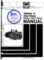
TRIVAC®'.'
Dual Stage
Rotary Vane Pump
MANUAL
LIMITED WARRANTY
Seller warrants to the original purchaser that the equipment to be delivered pursuant to this Agreement will be as described herein and will be free from defects
in material or workmanship. Minor deviations which do not affect the performance of the equipment shall not be deemed to constitute either a failure to conform to
the specifications or a defect in material'or workmanship.
This warranty shall extend for a period of twelve (12) months from the initial date of shipment. Should any failure of conformity to this warranty appear within twelve
(12) months from the initial date of shipment, Seller shall, upon immediate notifica'tion of such alleged failure and substantiation that the equipment has been operated
and maintained in accordance with Seller's recommendations and standard industry practices, correct such defects by suitable repair or replacement at its own expense.
Seller's liability under this warranty shall cease if any major repairs to or any replacement or modification of the equipment is made by any person other than Seller's
personnel or persons working under the supervision of Seller's personnel, unless authorized by Seller in writing. Further, the warranty shall cease unless the Buyer
has operated the equipment in strict compliance with operating instructions and manuals, if any, provided for the equipment. and unless Buyer operates the equipment
in normal use and with proper maintenance.
If the equipment contains components from another manufacturer and are subject to the manufacturer's warranty, then Seller's liability shall be limited to the extent
of the warranty which Seller received from the manufacturer or supplier of the equipment component parts. Seller's liability shall be no greater than the liability of
the manufacturer or supplier as determined by a final judgment by the Buyer against the manufacturer or supplier of such components. Seller will cooperate with
Buyer in such legal action but at Buyer's expense.
THIS WARRANTY IS EXPRESSLY IN LIEU OF ANY AND ALL REPRESENTATIONS AND WARRANTIES, EXPRESS OR IMPLIED, INCLUDING ANY WARRANTY
OF MERCHANTABILITY, FITNESS FOR A PARTICULAR PURPOSE OR OTHER WARRANTY OF QUALITY, EXCEPT THE WARRANTY OF TITLE. THIS WARRANTY
CONSTITUTES THE EXCLUSIVE REMEDY, and shall not be deemed to have failed of its essential purpose so long as Seller is willing and able to correct defects
covered by the warranty in the manner prescribed. The sole purpose of the exclusive remedy shall be to provide Buyer with free repair and/or replacement in the
manner and for the time period provided herein.
The entire agreement between the parties is embodied in this writing, which constitutes the final expression of the parties, and it is the complete and exclusive
statement of the terms of the agreement. No other warranties are given beyond those set out in this writing.
LIMITATION OF LIABILITY. SELLER SHALL NOT, UNDER ANY CIRCUMSTANCES, BE LIABLE FOR DIRECT OR INDIRECT, SPECIAL DAMAGES, INCIDENTAL
OR CONSEQUENTIAL, such as but not limited to, loss of profits, damage to or loss of other property, downtime costs of the equipment, delay expenses, overhead
or capital costs, claims of Buyer's customers or activities dependent upon the equipment.
Except to the extent provided in the LIMITED WARRANTY, Seller shall not be liable for any claim or loss arising out of or related to this agreement or the equipment
provided pursuant thereto, whether such claim allegedly arises or is based on contract, warranty, tort (including negligence), strict liability in tort or otherwise. Liability
shall not in any event exceed the cost of the equipment upon which such liability is based.
SEVERABILITY. If any portion or clause of this agreement is held invalid or unenforceable as to any person or under any circumstances, the invalidity or lack of
application shall not impair or affect the other provisions and the application of those provisions which can be given effect without the invalid or unenforceable provision
or application. With this intention, the provisions of this agreement are declared to be severable.
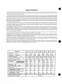
Pump Model
D2A
D4A
D8A
D30A
D16A
D60A
36.7
D90A
53.7
Displacement . ... CFM
2.2
Displacement. , .. literslminute
62.5
127
190
400
760
1030
1520
Ultimate partial pressure
3 x 10⁻⁴
3 x 10⁻⁴
3 x 10- 4
3 x 10⁻⁴
3 x 10⁻⁴
3 x 10- 4
3 x 10- 4
3 x 10⁻³
3 x 10⁻³ 3 x 10⁻³
3 x 10- 3
3 x 10- 3
5 x 10- 3
5 x 10- 3
Water vapor tolerance . ... Torr
30
15
30
15
40
20
20
Oil Capacity . ...... quarts (HYdrOCarbOn~
..... . Ibs (perfluoropolyether
0.5
2.5
0.75
1
1.25
4
4.2
5
3.5
13.7
4
3
16.8
16.8
Motor power .... hp
1/3
1/3
1
1
1·1/2
2.0
3.0
Pump rotational speed ... . RPM
1725 ~
1725
1725
1725
1725
1150
1725
Weight complete . ... Ib
41
45
80
85
163
210
210
Sound pressure level (max) at three feet with
gas ballast closed . .. . dB(A)
50
50
60
62
59
60
60
Sound pressure Iflvel (ave) at three feet with
gas ballast open . ... dB(A)
54
56
57
60
62
63
63
Intake tube and exhaust port diameter . ... mm
KF 16
KF Hi
KF 25
KF 25
KF 40
KF 40
KF 40
.... Torr
Ultimate pressure with gas ballast
Maximum ambient temperature
.... Torr
4.5
7.0
14.1
104°F (40oq
26.8
•
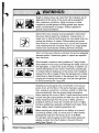
Death or serious injury can result from the improper use or
application of this pump. If the pump will be exposed to
toxic, explosive, pyrophoric, highly corrosive, or other
hazardous process gases including greater than atmospheric concentrations of oxygen, contact Leybold for
specific recommendations.
Ground the motor properly during installation. Disconnect
the power before beginning installation, maintenance, or
repair work or before interchanging the input leads when correcting the direction of rotation. Disconnecting the power
also avoids an unexpected start-up for pumps with automatically resetting thermal overloads. Most of our single-phase
motors have automatically resetting thermal overloads.
Don't run the pump without an exhaust line and an adequate
exhaust system if hazardous gases or vapors are expelled
from the pump.
Don't exceed a maximum back pressure of 7 psig. Excessive pressure in the pump could damage the seals, blowout
the sight glass, or rupture the pump housing. In addition, excessive backpressure can result in hazardous process gas
or contaminated oil leaking out of the pump. Don't install an
exhaust line with a smaller 10 than the exhaust port or allow
restrictions or deposit buildup in the exhaust line. If you are
purging the oil caSing with inert gas, limit the inert-gas flow .
to avoid exceeding the 7 psig limit.
Hazardous process gases can concentrate in the vacuum
pump, its oil, and its filters. If the pump has been used on
toxic, explosive, pyrophoric, corrosive, volatile, or other hazardous substances, take the proper safety· precautions
before opening the pump or filters. Proper precautions could
include inert gas purging before and after you drain the oil to
sweep hazardous gas from the pump or filters; gloves or
protective clothing to avoid skin contact with toxic or highly
corrosive substances; specially ventilated work areas; fume
hoods, safety masks; breathing apparatus; etc.
Before sending any equipment to our fadtory or to one of
our service centers, notify us of any toxic or other harmful
products that may be in the pump, its oil, or its filters.
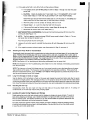
You will also needto supply us with the pump's serial and
catalog numbers from the 10 plate on the end of the oil
cas
Figure 1-1).
TRIVAC "A" Manual, Edition L
CONTENTS
Section
Page
Title
SECTION 1 -INTRODUCTION . . . . . . . . . . . . . . '. . . . . . . . . . . . . . . . . . . . . . . . . . . . . . . . . . . . . . . . . . .
3
1-1
1-2
Manual Key . . . . . . . . . . . . . . . . . . . . . . . . . . . . . . . . . . . . . . . . . . . . . . . . . . . . . . . . . . ........ .
Model and Catalog Numbers
.................................................. .
3
3
SECTION 2 - PRINCIPLES OF OPERATION. . . . . . . . . . . . . . . . . . . . . . . . . . . . . . . . . . . . . . . . . . . . . . ..
4
2-1
2-2
4
4
4
5
5
5
Direct Drive Mechanism. . . . . . . . . . . . . . . . . . . . . . . . . . . . . . . . . . . . . . . . . . . . . . . . . . . . . . . . . ..
Pumping Mechanism . . . . . . . . . . . . . . . . . . . . . . . . . . . . . . . . . . . . . . . . . . . . . . . . . . . . . . . . . . . ..
2-2-1 High Vacuum Stage Pump Cylinder. . . . . . . . . . . . . . . . . . . . . . . . . . . . . . . . . . . . . . . . . . . . ..
2-2-2 Second Stage Pump Cylinder. . . . . . . . . . . . . . . . . . . . . . . . . . . . . . . . . . . . . . . . . . . . . . . . . ..
Gas Ballast Mechanism. . . . . . . . . . . . . . . . . . . . . . . . . . . . . . . . . . . . . . . . . . . . . . . . . . . . . . . . . . ..
2-3-1 Opening and Closing the Valve. . . . . . . . . . . . . . . . . . . . . . . . . . . . . . . . . . . . . . . . . . . . . . . . ..
2-3-2 Purpose and Function . . . . . . . . . . . . . . . . . . . . . . . . . . . . . . . . . . . . . . . . . . . . . . . . . . . . . ..
Lubricating Fluid . . . . . . . . . . . . . . . . . . . . . . . . . . . . . . . . . . . . . . . . . . . . . . . . . . . . . . . . . . . . . ..
Anti-Suck Back Mechanism . . . . . . . . . . . . . . . . . . . . . . . . . . . . . . . . . . . . . . . . . . . . . . . . . . . . . . . . ,
7
8
SECTION 3 - PREPARING AND INSTALLING THE PUMP. . . . . . . . . . . . . . . . . . . . . . . . . . . . . . . . . . . . ..
8
3-1
8
8
8
9
2-3
2-4
2-5
6
Receiving.....................................................................
3-1-1 Reporting Shipping Damage . . . . . . . . . . . . . . . . . . . . . . . . . . . . . . . . . . . . . . . . . . . . . . . . . ..
3-1-2 Reporting Shipping Shortage. . . . . . . . . . . . . . . . . . . . . . . . . . . . . . . . . . . . . . . . . . . . . . . . . ..
3-1-3 Reporting Incorrect Shipment. . . . . . . . . . . . . . . . . . . . . . . . . . . . . . . . . . . . . . . . . . . . . . . . ..
Initial Filling With Lubricating Fluid. . . . . . . . . . . . . . . . . . . . . . . . . . . . . . . . . . . . . . . . . . . . . . . . . ..
Connecting the Pump to the System. . . . . . . . . . . . . . . . . . . . . . . . . . . . . . . . . . . . . . . . . . . . . . . . . ..
Making the Electrical Connection. . . . . • . . . . . . . . . . . . . . . . . . . . . . . . . . . . . . . . . . . . . . . . . . . . . ..
10
SECTION 4 - STARTING, OPERATING, AND MAINTAINING THE PUMP. . . . . . . . . . . . . . . . . . . . . . . . . ..
10
4-1
10
10
10
11
11
11
12
13
13
13
13
3-2
3-3
34
4-2
4-3
Start-up......................................................................
4-1-1 Checking the Direction of Rotation. . . . . . . . . . . . . . . . . . . . . . . . . . . . . . . . . . . . . . . . . . . . ..
4-1-2 Using the Gas Ballast Valve During Pump Warm-up. . . . . . . . . . . . . . . . . . . . . . . . . . . . . . . . . . ..
Operation ........ _ . . . . . . . . . . . . . . . . . . . . . . . . . . . . . . . . . . . . . . . . . . . . . . . . . . . . . . . . . ..
Preventative Maintenance. . . . . . . . . . . . . . . . . . . . . . . . . . . . . . . . . . . . . . . . . . . . . . . . . . . . . . . . ..
4-3-1 Checking the Lubricating Fluid Level . . . . . . . . . . . . . . . . . . . . . . . . . . . . . . . . . . . . . . . . . . . ..
4-3-2 Changing the Lubricating Fluid . . . . . . . . . . . . . . . . . . . . . . . . . . . . . . . . . . . . . . . . . . . . . . . ..
4-3-3 Checking the Lubricating Fluid for Contamination. . . . . . . . . . . . . . . . . . . . . . . . . . . . . . . . . . ..
4-3-4 Long Term Storage. . . . . . . . . . . . . . . . . . . . . . . . . . . . . . . . . . . . . . . . . . . . . . . . . . . . . . . ..
4-3-5 Checking the Dirt Trap. . . . . . . . . . . . . . . . . . . . . . . . . . . . . . . . . . . . . . . . . . . . . . . . . . . . . ..
4-3-6 Avoiding Oil Leaks During Shipping and Storage. . . . . . . . . . . . . . . . . . . . . . . . . . . . . . . . . . . ..
9
9
SECTION 5 - DISASSEMBLY, CLEANING, AND ASSEMBLY INSTRUCTIONS . . . . . . . . . . . . . . . . . . . . . . . , 14
Module Replacement Procedure. . . . . . . . . . . . . . . . . . . . . . . . . . . . . . . . . . . . . . . . . . . . . . . . . . . . ..
Required Materials and Tools. . . . . . . . . . . . . . . . . . . . . . . . . . . . . . . . . . . . . . . . . . . . . . . . . . . . . . ..
5-A-1 Required Materials. . . . . . . . . . . . . . . . . . . . . . . . . . . . . . . . . . . . . . . . . . . . . . . . . . . . . . . . ..
5-A-2 Required Tools. . . . . . . . . . . . . . . . . . . . . . . . . . . . . . . . . . . . . . . . . . . . . . . . . . . . . . . . . . ..
Removing the Module from the Pump. . . . . . . . . . . . . . . . . . . . . . . . . . . . . . . . . . . . . . . . . . . . . . . . ..
Disassembling the Module . . . . . . . . . . . . . . . . . . . . . . . . . . . . . . . . . . . . . . . . . . . . . . . . . . . ./.':. . ..
Disassembling the Remaining Parts . . . . . . . . . . . . . . . . . . . . . . . . . . . . . . . . . . . . . . . . . . . . .
0\ • •
Cleaning and Inspecting the Disassembled Pump . . . . . . . . . . . . . . . . . . . . . . . . . . . . . . . . . . . . . ' ..... ,
5-E-l Special ~equirements .for Extreme-C~rrosive Service Pumps .......... )' . . . . . . . . . . . . . . . ..
5-E-2 Instructions for Cleaning and Inspecting all Pump Models. . . . . . . . . . . . . . . . . . . . . . . . . . . . . . ..
Reassembling the Pump . . . . . . . . . . . . . . . . . . . . . . . . . . . . . . . . . . . . . . . . . . . . . . . . . . . . . . . . . ..
14
14
14
14
15
17
22
28
28
28
29
SECTION 6 - TROUBLESHOOTING. . . . . . . . . . . . . . . . . . . . . . . . . . . . . . . . . . . . . . . . . . . . . . . . . . . ..
43
SECTION 7 - PARTS LIST. . . . . . . . . . . . . . . . . . . . . . . . . . . . . . . . . . . . . . . . . . . . . . . . . . . . . . . . . . ..
55
5-A
5-B
5-C
5-D
5-E
5-F
TRIVAC "A" Manual, Edition L
J...
LIST OF TABLES
t
Table
Title
Page
SECTION 4 - STARTING, OPERATING, AND MAINTAINING THE PUMP
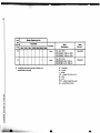
4-'
Technical Data . . . . . . . . . . . . . . . . . . . . . . . . . . . . . . . . . . . . . . . . . . . . . . . . . . . . . . . . . . . . . . . .
12
SECTION 5 - DISASSEMBLY, CLEANING, AND ASSEMBLY INSTRUCTIONS
5-1
5-2
Rotor, Bearing, Shaft, and Vane Critical Dimensions . . . . . . . . . . . . . . . . . . . . . . . . . . . . . . . . . . . . . . .
Parts Required for Installing Rotational Lock Bearing . . . . . . . . . . . . . . . . . . . . . . . . . . . . . . . . . . . . . .
30
32
SECTION 6 - TROUBLESHOOTING
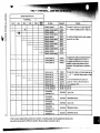
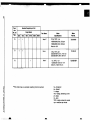
6-1
43
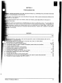
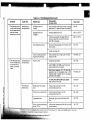
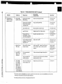
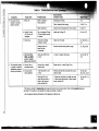
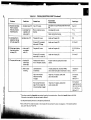
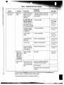
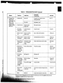
Troubleshooting Chart . . . . . . . . . . . . . . . . . . . . . . . . . . . . . . . . . . . . . . . . . . . . . . . . . . . . . . . . . . .
LIST OF FIGURES
Page
Title
Figure
SECTION 1 - INTRODUCTION
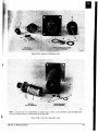
Sketch 1-1 Pump Identification Plate. . . . . . . . . . . . . . . . . . . . . . . . . . . . . . . . . . . . . . . . . . . . . . . . . . . . . . . . . . . . . .
1-1
Location ofthe Identification Plate, the Oil Fill Ports and the Oil Drain Ports. . . . . . .. . . . . . . . .. . . . .. . . .
3
4
SECTION 2 - PRINCIPLES OF OPERATION
Sketch 2-1 Cross Section of the Gas Ballast Valve on the DBAJAC through D90AJAC Extreme-Corrosive Service
Pumps ....................................................... :.................................
2-1
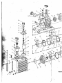
D4A Module. . . . . . . . . . . . . . . . . . . . . . . . . . . . . . . . . . . . . . . . . . . . . . . . . . . . . . . . . . . . . . . . ..
2-2
High Vacuum-Stage Pump Cylinder with Rear End Plate Removed. . . . . . . . . . . . . . . . . . . . . . . . . . . . ..
2-3
Gas Ballast Valve and Second Stage Pump Cylinder with Front End Plate Removed. . . . . . . . . . . . . . . . . ..
7
5
5
6
SECTION 5 - DISASSEMBLY, CLEANING, AND ASSEMBLY INSTRUCTIONS
5-1
5-2
5-3
5-4
5-5
5-6
5-7
5-8
5-9
5-lOA
5-10B
5-11
5-12
5-13
5-14
5-15
5-16
5-17
5-18
5-19
5-20
5-21
5-22
5-23
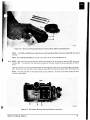
Assembled Pump (D16A Pump Model Shown) . . . . . . . . . . . . . . . . . . . . . . . . . . . . . . . . . . . . . . . . . .
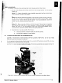
Module Attached to Coupling Housing (D2A Pump Model Shown) . . . . . . . . . . . . . . . . . . . . . . . . . . . . ..
Module, Side View (D2A Pump Model Shown) . . . . . . . . . . . . . . . . . . . . . . . . . . . . . . . . . . . . . . . . . ..
Front End of Module Minus Coupling and Centrifugal Switch (D2A Pump Model Shown). . . . . . . . . . . . . ..
Removing the Cylindrical Pins from the Module (D2A Pump Model Shown). . . . . . . . . . . . . . . . . . . . . . ..
Rear End of Module Minus the Disk (D2A Pump Model Shown). . . . . . . . . . . . . . . . . . . . . . . . . . . . . . ..
High Vacuum Stage Pump Cylinder (D2A Pump Model Shown). . . . . . . . . . . . . . . . . . . . . . . . . . . . . . ..
Second Stage Pump Cylinder (D2A Pump Model Shown) . . . . . . . . . . . . . . . . . . . . . . . . . . . . . . . . . . ..
High Vacuum Stage Rotor Removed from the Shaft (D2A Pump Model Shown) . . . . . . . . . . . . . . . . . . . . ,
Cap End of Gas Ballast Valve. . . . . . . . . . . . . . . . . . . . . . . . . . . . . . . . . . . . . . . . . . . . . . . . . . . . . ..
Tube End of Gas Ballast Valve. . . . . . . . . . . . . . . . . . . . . . . . . . . . . . . . . . . . . . . . . . . . . . . . . . . . ..
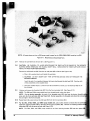
Miscellaneous Disassembled Parts . . . . . . . . . . . . . . . . . . . . . . . . . . . . . . . . . . . . . . . . . . . . . . . . . . . .
Removing the Radial Shaft Seal from the End Plates (D2A Pump Model Shown) . . . . . . . . . . . . . . . . . . . . .
D4A Module Showing Retaining Bracket and Valve Plate . . . . . . . . . . . . . . . . . . . . . . . . . . . . . . . . . . . ,
Removing the Valve Stop and Plate (D2A Pump Model Shown) . . . . . . . . . . . . . . . . . . . . . . . . . . . . . . ..
Coupling Housing and Motor (D2A Pump Model Shown) . . . . . . . . . . . . . . . . . . . . . . . . . . . . . . . . . . ..
Removing the Oil Level Glass from the Coupling Housing (D2A Pump Model Shown) . . . . . . . . . . . . . . . ..
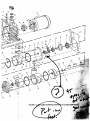
Disassembled Motor (D30A Motor Shown). . . . . . . . . . . . . . . . . . . . . . . . . . . . . . . . . . . . . . . . .. . . ..
Rotors/Shaft/Center Bearing Plate Assembly (D2A Pump Mod~ Shown). . . . . . . . . . . . . . . . . . . . . . . . ..
Driving the Long Cylindrical Pins that Align the HV Stage Cylinder and the Center Bearing
(D2A Pump Model Shown) . . . . . . . . . . . . . . . . . . . . . . . . . . . . . . . . :-; . . . . . . . . . . . . . . . . . . . . ..
Pulling the Second Stage Cylinder Tight Against the Center Bearing (D2A Pump Model Shown). . . . . . . . . ..
Driving the Short Cylindrical Pins that Align the Rear End Plate and the HV Stage Cylinder
(D2A Pump Model Shown) . . . . . . . . . . . . . . . . . . . . . . . . . . . . . . . . . . . . . . . . . . . . . . . . . . . . . . ..
Using a Shaft Sleeve to Install the Radial Shaft Seal into the Front End Plate (D2A Pump Model Shown) . . ..
Reassembling the Module to the Coupling Housing . . . . . . . . . . . . . . . . . . . . . . . . . . . . . . . . . . . . . . ..
16
17
18
19
20
20
21
21
22
23
23
24
25
25
26
26
27
32
35
36
38
39
40
42
SECTION 7 - SPARE PARTS LIST
7-1
Disassembled Pump (D2A Pump Model Shown) . . . . . . . . . . . . . . . . . . . . . . . . . . . . . . . . . . . . . . . . ..
7-2
Exploded Isometric Drawing of a D30A Pump Model. . . . . . . . . . . . . . . . . . . . . . . . . . . . . . . . . . . . . . . . . . . .. 73
..,
TRIVAC "A" Manual, Edition L
56
"
SECTION 1
INTRODUCTION
This manual contains important information regarding the safe operation, maintenance, and repair of your TR IVAC
dual-stage pump. We urge you to read Sections 1,3, and 4 before using your pump. Section 6, the troubleshooting chart,
should be used in conjunction with the rest of the manual should the need occur.
1-1
MANUAL KEY
This manual covers the following pump models (see Section 1-2) in addition to extreme-corrosive service pumps.
Standard
Series
D2A
D4A
D8A
D16A
D30A
D60A
D90A
Corrosive
Appl ication
Series
Dual-Speed Standard
and Corrosive
Application Series
D2AC
D4AC
D8AC
D16AC
D30AC
D60AC
D90AC
D60A2X
D60AC2X
"WARNING" statements are used in this manual to prevent injury to personnel; "CAUTION" statements are
used to prevent damage to equipment. "NOTES" contain helpful information. "REQUI RED ACTION" is used
where necessary to distinguish the action of the step from the WARN INGS, CAUTIONS, and NOTES.
Numbers in parentheses refer to position numbers of parts in the parts list (see Section 7). These numbers
are also used to identify parts on the figures.
The terms "lubricating fluid," "pump fluid," "fluid," "oil," and "lubricant" when used in this manual refer to the
"proper vacuum pump fluid."
1-2
MODEL AND CATALOG NUMBERS
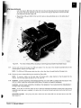
To understand many of the instructions in this manual, you need to know the model number of your pump. The
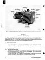
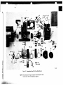
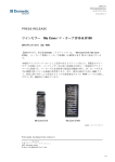
plate attached to the end of the pump (see Figure 1-1) lists the model, catalog, and serial numbers in addition to
the catalog number of the standard oil for the pump.
Always supply us with the pump's serial and catalog numbers when returning it to one of our service centers.
Also report the serial number of the pumping system where applicable.
~
TRIVAC®
LEYBOLD
MODEL NO.
CATALOG NO. _____________________________
SERIALNO. _________________________~_\_____
THIS PUMP FI LLED WITH
LEYBOLD VACUUM PRODUCTS INC.
5700 Mellon Road Export, PA.15632
MADE IN U.S.A.
lTA·l
Sketch 1-1. Identification Plate
TRIVAC is a registered trademark of Leybold
TRIVAC "A" Manual, Edition L
3
011:' DRAIN PORTS
WITH PLUG SCREW (81
lTA·2.t
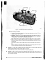
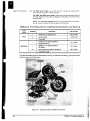
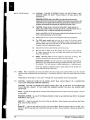
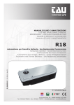
Figure 1-1. Location of the Identification Plate, the Oil Fill Ports and the Oil Drain Ports (D30A Pump Model Shown).
SECTION 2
PRINCIPLES OF OPERATION
Vacuum pumps are used to reduce the pressure in an enclosed vessel or system. For rough and medium vacuums
(760 to 10-3 Torr), the intake tube (1) of the rotary vane pump is connected to the vessel to be evacuated. For high or
ultrahigh vacuum (10- 3 to 10- 11 Torr), the rotary vane pump is used as a backing or roughing pump and is connected in
series and/or parallel with other types of pumps which are designed to obtain a high vacuum.
2-1
DIRECT DRIVE MECHANISM
When the motor is switched on, the motor shaft turns the pump shaft. The motor shaft and pump shaft are connected directly through a coupling (37) and an elastic element (36) (see Figure 5-23). The elastic element (36)
absorbs shock and vibration and results in quiet operation of the pump.
2-2
2-2-1
PUMPING MECHANISM
High Vacuum Stage Pump Cylinder
The pump intake tube (1) fits into the top of the high vacuum stage pump cylinder (55). The shaft and attached
rotor (54) are mounted eccentrically in the high vacuum stage housing (52/60/55). Three rectangular vanes (53)
fit into slots in the rotor (54) (see Figures 2-1 and 2-2).
As the shaft and rotor (54d rotate, centrifugal force pushes the vanes (53) out against the pump cylinder (55)
inner surface (see Figure 2-2). The three vanes divide the cylinder into chambers 120 0 apart.
4
TRIVAC "A II Manual, Edition L
•
1TA·3.t4
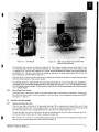
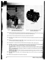
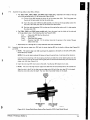
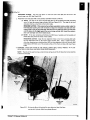
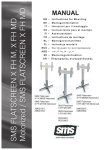
Figure 2·1.
D4A Module
Figure 2·2.
High Vacuum Stage Pump Cylinder With
Rear End Plate Removed
One pumping cycle proceeds as follows (see Figure 2-2). Gas is drawn through the pump intake tube (1) into
an increasingly large vacuum tight chamber (Chamber A). The rotation increases the size of the chamber until
it is sealed off by a second vane (Chamber B). Further rotation diminishes the chamber size and compresses the
gas (Chamber C). The gas is then forced out through an opening in the center bearing plate (52) and into the
second stage pump cylinder (46) (see Figure 2·1).
With each cycle, the pump removes a portion of the original gas contained in the vessel or system being evacuated,
until the ultimate pressure of the pump is reached.
The ultimate pressure is measured with the pump intake tube closed off. It is the lowest pressure attainable for
a particular pump. The ultimate partial pressure for dual stage vane pumps is 3 x 10⁻⁴ Torr as measured with a
LN z cold-trapped ionization gauge. Ultimate pressure measured with thermocouple gauges will be approximately
1/2 to 1 decade higher.
2-2·2
Second Stage Pump Cylinder
The second stage of the pump is similar to the high vacuum stage in construction and operation. It accepts gas
from the high vacuum stage, further compresses it, and then forces it out through the exhaust valve (50/51)
(see Figures 2-1 and 2·3).
2-3
2-3-1
GAS BALLAST MECHANISM
Opening and Closing the Valve
There are two holes in the side of the gas ballast valve cap (18) on standard pump models. When one of these
holes is aligned with the hole in the gas ballast valve (17), the valve is open (see Figure 2-3). When the side of the
cap (18) is covering the hole in the gas ballast valve (17), the valve (17) is closed (see Figure 1-1).
To open the valve, turn the cap (18) until a cap hole is aligned with the valve (17) hole; to close the valve (17),
turn the cap (18) so that the valve (17) hole is covered by the cap (18).
When the valve (17) is open, air at atmospheric pressure rushes in the cap-end hole, through the gas ballast valve
stem and into the second stage pump cylinder (46) (see Figure 2-3).
TRIVAC "A" Manual, Edition L
5
,--
EXHAUST HOLES
\
\
\
51
\
I
lTA·S.l
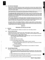
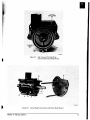
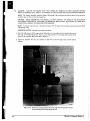
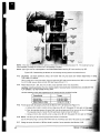
NOTE: This photograph is for illustration purposes only. When assembled, the cap end of the gas ballast valve
(17) is attached outside the top of the oil casing (12) (see Figure 1·1), and an oil filter (35) and other parts fit
around the valve (17) stem (see Figure 5·10B).
Figure 2-3. Gas Ballast Valve and Second Stage Pump Cylinder With Front End Plate Removed
2-3-2
Purpose and Function of the Gas Ballast Valve
All systems contain moisture. Some processes have large quantities of condensable vapors in the process gas.
When these vapors condense in the pump, they degrade the lubricating and sealing qualities of the pump fluid
(see Section 2-4) resulting in excessive pump wear, higher base pressure, and sometimes pump seizure.
The gas ballast valve allows removal of condensable vapors and condensate such as water, alcohol, gasoline.
benzene, carbon tetrachloride, etc. from the pump. It also enables high levels of water vapors to be pumped
without condensation. The water vapor tolerance for your pump is listed in Table4-1. If the partial pressure of
water vapor in the gas being pumped exceeds the tolerance of your pump, the vapor will condense. We
recommend installing an AK condensate trap on the pump when pumping saturated vapors (see Section 1 of
our catalog for more information on condensate traps).
(
When the gas ballast valve (17) is open, it admits a controlled amount of air into the second stage pump cylinder
(46) just before the exhaust holes (see Figure 2-3). The open gas ballast valve prevents vapors from condensing
by reducing the partial pressure of the condensable vapors and by increasing the operating temperature of the
pump.
11
("
The gas ballast valve is not fully effective until the pump is warm to the touch. When using the gas ballast valve
to remove condensate from the pump fluid, it is best to seal off the intake tube (1). Sealing off the intake tube
(1) prevents additional vapors from entering the pump while the condensate is being vaporized and the vapor is
being ejected. See Sections 4-1-2 and 4-2 for instructions for using the gas ballast valve during start-up and operation.
In addition to increasing the operating temperature, running the pump with the gas ballast valve open also results
in higher ultimate pressure (see Table 4-1), higher pump fluid consumption, and a pump fluid mist in the exhaust
stream. If you run the pump with the gas ballast valve open continuously, we recommend an SE smoke eliminator
or an AF exhaust filter with an oil return line. After closing the gas ballast valve the pump normally reaches ultimate
pressure as soon as it cools to operating temperature.
6
TRIVAC "A" Manual, Edition L
•
•
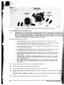
NOTE: On extreme-corrosive service pumps, the gas ballast valve (17) is sealed to prevent gases in the air
~rom r~acting wit,h secondary, gases or vapors in t~e pump, These pumps have a port on the valve (17) for
Installing a dry nitrogen gas line (see Sketch 2-1); the port is Va inch NPT for the D2A and D4A models and
V4 inch NPT for alT other TRIVAC A models, The maximum nitrogen pressure is 2 psig delivered to the pump,
,
I'
i
I
)
ADAPTER WITH
NPT PORT
EPOXY SEAL
This isn't a standard
modification; it is
.made primarily to
extreme-corrosive
service pumps.
GAS BALLAST VALVE (17)
SEALED WITH EPOXY
RETAINING WASHER (21)
lTA-1.2
Sketch 2-1 Cross Section of the Gas Ballast Valve on the DaAlAC Extreme-Corrosive Service Pumps.
t
2-4
PUMP FLUID
The pump fluid partially fills the oil casing (12). It is injected from the oil casing (12) into the module through
one or two oil nozzles (56) located in the second stage pump cylinder (46) (see Figure 5-8). Pump fluid consump·
tion is minimal during normal operation, but increases when operating at high pressures or with the gas ballast
valve open.
In addition to lubricating the moving parts, the pump fluid seals the clearances in the pumping module. This
fluid seal is necessary for achieving the ultimate pressure of the pump. The pump fluid also transfers heat from
the pumping element to the oil casing (12).
Other important qualities of the pump fluid include the following:
-It must have a low vapor pressure at the high temperature generated by gas compression and vane friction.
-It must be oxidation resistant.
-It must have a low water absorption rate.
-It must resist cracking under the mechanical stress of gas compression and vane pressure.
Based on operational testing, we have approved the following vacuum pump fluids for use in TRIVAC "A" pumps:
Standard Applications
HE-175 (hydrocarbon)
Corrosive Applications
HE-200 or HE-400 (hydrocarbon)
Extreme-Corrosive Applications
H E-1600 (perfluoropolyether)
High·Temperature Applications
HE-600 (synthetic diester hydrocarbon)
If you use a nonapproved pump fluid, we can't guarantee that our pumps will meet their operating specifications
(ultimate pressure, pumping speed, operating temperature, etc.). However, the warranty is voided only if the nonapproved fluid adversely affects the operation or reliability of the pump. The pump's identification plate (see
Page 3) indicates which pump fluid was initially used in the pump.
I
Section 2-3-2 mentions the detrimental effects of condensate on the pump fluid. Contaminants also destroy many
of the essential qualities of the fluid, resulting in pump wear, slower pumping speed, higher ultimate pressure, and
sometimes pump seizure. Change the pump fluid frequently to ensure good performance and to extend the life of
your pump.
TRIVAC ''A" Manual, Edition L
7
2-5
ANTI-SUCK BACK MECHANISM
When the pump is intentionally turned off or if there is a power failure, the anti-suck back mechanism seals the
intake tube (1) and vents the pumping chamber. The pump starts easier when the pumping chamber is vented.
The sealing of the intake tube (1) prevents pump fluid from surging back into the vacuum line and maintains the
vacuum in the vessel or system.
The primary components of the anti-suck back mechanism are the centrifugal switch (39), the lever (41) with spring
(42) and seal (43), the air inlet tube (69), and the piston (68) with valve disk (67) (see Figure 2-1).
The centrifugal switch (39) is attached to the shaft. When the pump is turned off, the shaft rotation slows, causing
the centrifugal switch (39) to push against the lever (41). As a result, the lever (41) opens the air inlet tube (69)
(see Figure 2-1). Air at atmospheric pressure rushes through the open tube (69) and into the high vacuum stage
pump cylinder (55), thus venting the pump. This air also forces the brass piston (68) and attached valve disk (67)
to seal the pump intake tube (1).
When the pump is started again, the shaft rotation causes the centrifugal switch (39) to pull away from the lever
(41). A spring (42) pushes the lever in the opposite direction, causing the seal (43) attached to the lever to close
the air inlet tube (69). The suction of the pump draws the valve disk (67) and attached piston (68) away from the
opening in the intake tube (1) allowing the pump to further evacuate the vessel or system.
On AC pump models, the anti-suckback mechanism is modified to avoid exposing the pumping module to
atmospheric air and to avoid the possibility of h!izardous process gas escaping from the pump during shutdown.
The centrifugal switch and lever assembly are removed and a solenoid valve with tubing is added so that the module
is vented with gas from the oil casing during shutdown.
SECTION 3
PREPARING AND INSTALLING THE PUMP
3-1
RECEIVING
NOTE: The Leybold packing list is attached to the outside of one of the shipping containers.
3-1-1
Reporting Shipping Damage
Leybold makes every effort to ensure that your order is packed properly. However, rough or careless
handling in transit occasionally results in shipping damage. In such cases, the carrier is responsible for the damages.
Unpack the pump and check for shipping damage as follows:
1. Inspect the outside of the shipping container for shipping damage. If you will be making a damage claim,
save the shipping container and packing materials.
2. Unpack the pump.
3. Carefully inspect the pump for damage.
4. If you find any damage, proceed as follows:
a. Save the shipping container, packing material, and parts for inspection.
b. Notify the carrier that made the delivery within 15 days of delivery in accordance with Interstate
Commerce regulations.
c. File a claim with the carrier.
d. Contact the Leybold Order Services Department to make arrangements for replaCing
the damaged part.
3-1-2
.~
Reporting Shipping Shortage
If you did not receive all the goods that you ordered, do the following:
1. Check the number of pieces listed in the upper right section of the packing list If the number of pieces
listed is greater than the number of shipping containers received, contact the carrier concerning the missing
.
y
piece.
2. Check the packing list to see if the missing item is back ordered.
3. Carefully check the packing material and container to ensure that you did not overlook the missing item.
4. If you cannot find the item, contact our Order Services Department.
8
TRIVAC "A" Manual, Edition L
..
..i~.
"';]
:~
,
.+'
? ~ ~
Reporting Incorrect Shipment
If the item received is not the item ordered, contact our Order Services Department.
3-2
INITIAL FILLING WITH PUMP FLUID
The larger pump models are shipped filled with pump fluid; the smaller pump models are shipped with the pump
fluid in a separate container. Ensure that the oil is in the middle to upper third of the sight glass before starting
the pump (see Figure 1-1).
3-3
CONNECTING THE PUMP TO THE SYSTEM
KF® clamp rings are supplied for the intake and exhaust ports of the pump. A centering ring with dirt trap (2) is suppHed for the
intake tube (1) and a centering ring with O-ring (7) is supplied for the exhaust port (6).
Leybold also has a complete line of components, fittings, and adapters'to connect your pump to any system. See
our catalog for a list of these components. See Table 4-1 for the intake and exhaust flange dimensions of your
pump model.
All connections must be vacuum tight for your pump to achieve its ultimate pressure. The O-ring on the centering
rings must be clean to avoid leaks.
Your pump will perform better and last longer if it is protected by the correct inlet filter and/or oil filtering system. See our catalog or contact your nearest sales office for the recommended filter for your application.
Any accessories, such as coaxial traps, dust separators, exhaust filters, or inlet filters should be connected after
Step 2 below. Use the manual that comes with each accessory for installing, maintaining, and operating the accessory (see the Leybold c.atalog for additional information on accessories).
CAUTION: IF YOU ARE PURGING THE GAS BALLAST VALVE, DO NOT EXCEED AN INERT GAS PRESSURE
OF 2 psig; IF YOU ARE PURGING THE OIL CASE OR EXHAUST LINE WITH INERT GAS, DO NOT RAISE THE
PRESSURE IN THE OIL CASING ABOVE 3 psig. EXCEEDING THESE PRESSURES WILL DEGRADE THE PUMP'S
PERFORMANCE.
Connect the pump to your system as follows:
1. Set the pump on a horizontal surface. It need not be permanently mounted on the surface (See
Figure 1-1).
2. CAUTION: FAILURE TO REMOVE THE SHIPPING WEDGE OR EXHAUST PORT COVER
BEFORE STARTING THE PUMP COULD RESULT IN DAMAGE TO THE PUMP.
Remove and discard the protective cover from the pump intake tube (1) and exhaust port (6) and
the metal shipping disc from the exhaust port (see Figure 7-2, the foldout). Also remove and discard the red plastic shipping wedge from underneath the coupling housing (11). A Day-Glo orange
tag attached to the pump contains instructions for removing the shipping wedge.
3, CAUTION: ENSURE THAT THE VACUUM LINE IS CONNECTED TO THE INTAKE TUBE (1)
AND NOT TO THE EXHAUST PORT (6) (see Figure 1-1), CONNECTING THE VACUUM LINE
TO THE EXHAUST PORT (6) COULD RESULT IN DAMAGE TO THE PUMP OR TO YOUR
SYSTEM.
NOTE: Ideally, the inside diameter (10) of the vacuum line should be the same size or larger than
the 10 of the intake tube (1). If the vacuum line is too narrow, it will reduce the pumping speed.
REQUIRED ACTION: Using the KF clamp ring and the centering ring with dirt trap (2) and
a-ring (3), connect the pump intake tube (1) to the vacuum line.
®KF is a registered trademark of Leybold
TRIVAC HAlt MSrtulJl,Edition L
9
install an exhaust line with a smaller 10 than the exhaust port or have restrictions
valves in the exhaust line during operation. Such restrictions reduce the pumping speed
damage the oil seals or cause a dangerous overpressure in the pump.
Using the KF clamp ring and the centering ring with an O-ring (7), make one of the following
connections to the exhaust port (6).
a. If practicable, install the exhaust line at a slightly descending angle to prevent condensate
from flowing back into the pump and contaminating the pump fluid. Attach a drain
valve at the lowest point in the exhaust line to drain off any condensates; then run the
exhaust line up to its emission outlet. This arrangement also prevents particulates from
dropping back into the pump from the exhaust line.
b. If the exhaust line must be installed in the ascending position and the process gas contains
high levels of condensable vapors, connect an AK condensate trap to the exhaust port. AK
traps serve to collect the condensates from saturated vapors, See Section 1 of our catalog
for additional information on condensate traps.
c. If no exhaust line is connected and your pump will be running above 1 Torr inlet pressure,
connect an AF or SE series exhaust filter to the exhaust port (6) to remove pump fluid vapors and smoke. See Section 1 of our catalog for additional information on exhaust filters.
5. If the exhaust line is attached to a negative pressure exhaust system, adjust the negative pressure
so that pump fluid will not be drawn from the pump.
3-4
MAKING THE ELECTRICAL CONNECTION
When making the electrical connections for your motor, ensure that everything is grounded properly. Six-foot
linecords are supplied on all standard single-phase 60-HZ motors that are purchased through Leybold. Most
of our single-phase motors also have automatically resetting thermal overloads. If the motor doesn't have a
linecord, you must provide the correct thermal overloads to protect the motor.
For 3-phase motors, use the schematic diagram on the motor nameplate or in the junction box to make the
electrical connection.
For TRIVAC~AC?pump models with 3-phase motors, wire the solenoid valve for high or low voltage according
to the instructions on the solenoid-valve nameplate. Attach the solenoid-valve leads to any two of the three input
line voltage wires.
SECTION 4
ST ARTING, OPERATING, AND MAINTAINING THE PUMP
4-1
4-1-1
START-UP
Before starting the pump, remove the shipping wedge; an orange cardboard tag on the pump has instructions tor
.
removing the wedge. The AC pump models don't have a wedge or a tag.
The motor manufacturer guarantees a maximum of six starts per hour at maximum power. To avoid exceeding six starts per hour, run the pump continuously and regulate the vacuum in y.our system with a valve.
Check the Direction of Rotation
Refer to Section 5, Step F-1 to check the direction of motor rotation. Looking from the motor end of the pump, the
motor fan should rotate clockwise. If the fan doesn't rotate in the correct direction, turn the pump off immediately
to avoid damaging the motor or the pump.
4-1-2
Using the Gas Ballast Valve During Pump Warm-up
NOTE: Opening the gas ballast valve (17) results in an oil mist in the exhaust stream and higher pump fluid consumption, operating temperature, and ultimate pressure. After closing the gas ballast valve, the pump normally
reaches ultimate pressure as soon as it cools to operating temperature.
CAUTION: PUMPING PROCESS GAS WITH A COLD VANE' PUMP CAN RESULT IN VAPORS CONDENSING
IN THE PUMP FLUID.
1. Operate the pump with tlie gas ballast valve (17) open (see Section 2-3-1) and the intake tube (1)
closed for about V2 hour while the pump is warming to operating temperature.
NOTE: If your system has a valve in the vacuum line, the intake tube (1) can be closed by shutting
the vacuum-line valve during the pump warming period.
NOTE: When the pump is cold, condensation may occur in spite of the gas ballast valve being open.
2. Open the intake tube (1) and/or vacuum-line valve and allow the pump to operate for a few additional minutes with the gas ballast valve (17) open. This will remove condensable vapors from the
system.
10
TRIVAC "A" Manual, Edition L
•
~
3. NOTE: Most of the vapors have been expelled from the pump when the pressure nears the "ultimate
total pressure with gas ballast" (see Table 4-1).
NOTE: If your process has high levels of condensable vapors, it may be necessary to run the vane
pump with the gas ballast valve open (see Section 2-3-2). When running continuously with the gas
ballast valve open, we recommend installing an SE smoke eliminator or an AF exhaust filter with
a return line.
Close (see Section 2-3-1) the gas ballast valve (17) after all vapors have been pumped out of the
system or when there is only a small accumulation of vapor with a large excess of permanent gases.
4-2
OPERATION
WARNING: Don't pump toxic, pyrophoric, or hazardous gases unless your pump has the anti-suckback solenoid
valve modification (see Pages 8 and 57). When pumping these hazardous gases, we recommend a negative pressure
exhaust system and inert gas purging of the oil casing and gas ballast valve. In addition, a pump specially prepared
for perfluoropolyether vacuum oil is required for pumping highly reactive or extremely corrosive gas. Contact the
factory for recommendations.
CAUTION: Pumping corrosive gases with a standard pump can result in premature failure. Contact the factory for
pump modifications for your particular process.
CAUTION: RUNNING THE PUMP AT GREATER THAN 1 TORR INLET PRESSURE RESULTS IN AN OIL
MIST IN THE EXHAUST STREAM. INSTALL AN EXHAUST FILTER (SEE SECTION 3-3) AND CHECK THE
PUMP FLUID LEVEL FREQUENTLY (SEE SECTION 4-3-1) WHEN OPERATING THE PUMPABOVE 1 TORR
CAUTION: DO NOT RUN THE PUMP CONTINUOUSLY AT GREATER THAN 300 TORR INLET PRESSURE FOR
THE D2A, D8A, AND D30A PUMP MODELS OR GREATER THAN 187 TORR FOR THE D4A, D16A, D60A, AND
D90A PUMP MODELS.
The 115/230 V, 50/60 Hz, single-phase motors have an automatically resetting thermal overload.
If this overload shuts off the pump and the ON/OFF switch is left ON, the motor will restart itself
as soon as it cools down.
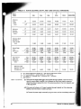
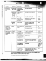
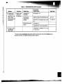
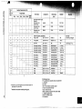
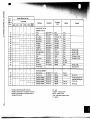
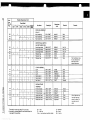
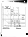
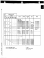
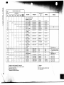
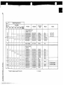
Table 4-1 lists operating and other technical data for each of the TRIVAC dual-stage vane pump models.
1. NOTE: The pump fluid is usually saturated with condensate when the fluid becomes milky white
or dark and the pump runs hot and fails to reach its ultimate pressure (see Table 4-1).
REQUIRED ACTION: If during operation, the pump fluid becomes saturated with condensate,
run the pump with the intake tube (1) and/or vacuum-line valve closed and the gas ballast valve
(17)open (See Section 2-3-1) until the condensate is vaporized and expelled from the exhaust
port (6).
2. If condensate in the pump fluid is severe, the pump should be flushed out and the pump fluid changed
(see Section 4-3-2). See Symptom 1 of the Troubleshooting Chart (Table 6-1) for other methods
of removing condensate from the pump fluid.
4-3
PREVENTATIVE MAINTENANCE
NOTE: See Section 6 (Troubleshooting) to resolve corrective maintenance problems.
4-3-1
Checking the Pump Fluid Level
NOTE: When the pump is not running, the pump fluid level appears lower.
NOTE: It is not unusual for the pump fluid to foam because of the churning action of the disk (oil slinger).
Foaming is more pronounced at high operating pressures. If only foam is visible in the oil level glass (15), it
means that the pump fluid level is low.
Occasionally check the pump fluid level when the pump is running near its ultimate pressure (see Table 4-1) and
the gas ballast valve (17) is closed.
The minimum pump fluid level is reached when the fluid surface is visible at the lower rim of the oil level glass
(15) or at the "L" mark on the oil sight gauge (72) (See Figure 1-1). If the pump fluid level is low, use Section 43-2, Steps 7, 8, and 9 to add the appropriate amount of the correct fluid.
The maximum pump fluid level is reached when the fluid surface is at the top rim of the oil level glass (15) or at
the" H" mark on the oil sight gauge (72). If the pump fluid level is too high, use Section 4-3-2, Steps 1,3, and 5 to
drain some fluid. Recheck the oil level while the pump is running to ensure that the fluid level is correct.
TRIVAC "A" Manual, Edition L
11
\f/
TABLE 4-1. TECHNICAL DATA
Pump Model
Displacement .... CFM
D2A
2.2
D4A
4.5
DBA
D1GA
D30A
7.0
14.1
26.8
D90A
D60A
36.7
53.7
Displacement .... I iters/minute
62.5
127
190
400
760
1030
1520
Ultimate partial pressure+ t .... Torr
3 x 10- 4
3 x 10⁻⁴
3 x 10⁻⁴
3 x 10⁻⁴
3 x 10⁻⁴
3 x 10⁻⁴
3 x 10⁻⁴
Ultimate pressure with gas ballast + .... Torr
3 x 10- 3
3 x 10- 3
3 x 10- 3
3 x 10- 3
3,x 10- 3
5 x 10- 3
5 x 10- 3
Water vapor tolerance .... Torr
30
15
30
15
40
20
20
Oil Capacity. , ..... quarts (hydrocarbon)
... Ibs (perfluoropolyether)
0.5
2.5
0.75
3
1
4.2
1.25
5
3.5
13.7
4
16.8
4
16.8
Motor power .... hp
1/3
1/3
1
1
1·1/2
2.0
3.0
Pump rotational speed .... RPM
1725
1725
1725
1725
1725
1150
1725
Weight complete .... Ib
41
45
80
85
163
210
210
Sound pressure level (max) at three feet with
gas ballast closed .... dB(A)
50
50
60
62
59
60
60
Sound pressure level (ave) at three feet with
gas ballast open .... dB(A)
54
56
57
60
62
63·
63
Intake tube and exhaust port diameter .... mm
KF'16
KF'16
KF *25
KF'25
KF*40
KF'40
Maximum ambient temperature
.
KF*40
104°F (40°C)
t The ultimate pressure + of pumps filled with perfluoropolyether fluid is 9 x 10⁻⁴ Torr except for 50-Hz D60A pump models. The
ultimate pressure of D60A pumps with perfluoropolyether fluid and with 50-Hz motors is 3 x 10⁻³ Torr.
+ The "ultimate partial pressure" is measured with an LN2 trapped ionization gauge. The "ultimate pressure with gas ballast" is
measured with a Kammerer Type McLeod Compression Gauge. Both of these pressures can be,as much as a decade higher When.
measured with a thermal conductivity gauge.
* KF - Leybold quick assembly clamp ring diameter.
4-3-2
Changing the Pump Fluid
WARNING: IF THE PUMP HAS BEEN USED ON CORROSIVE, TOXIC, OR VOLATILE CHEMICALS, OBSERVE
PROPER SAFETY PRECAUTIONS BEFORE REMOVING THE PLUG SCREW (8).
CAUTION: HYDROCARBON PUMP FLUID SHOULD BE CHANGED ATTHE FOLLOWING TIMES: (a) AFTER
A 100-HOUR BREAK-IN PERIOD OF PUMP OPERATION, (b) WHEN THE PUMP FLUID IS CONTAMINATED (see
Section 4-3-3), (c) WHEN CONDENSATION IN THE PUMP FLUID IS SEVERE (see Section 4-2), AND (d) BEFORE
AND AFTER THE PUMP IS STORED FOR A LENGTHY PERIOD (see Section 4-3-4). PERFLUOROPOLYETHER
FLUID SHOULD BE RECONDITIONED WHEN IT BECOMES CONTAMINATED.
NOTE: Always change the pump fluid while the pump is warm to prevent condensables from remaining in the pump.
Turn the pump off and change the fluid as follows:
1. Ensure that the pump is turned off; then place an appropriate container under one of the oil drain ports
to catch the used pump fluid.
2. If a negative pressure exhaust system is attached to the exhaust line of the pump, disconnect it.
NOTE: A negative exhaust pressure prevents the pump fluid from draining completely.
3. SEE THE SECTION 4-3-2 WARNING-Using an 8 mm allen wrench, unscrew and remove the
plug screw (8) from one of the oil drain ports and allow the fluid to drain from the pump (See
Figure 1-1).
4. When the flow of fluid slows, briefly switch the pump ON and OFF to drain the remaining fluid.
5. Using an 8-mm allen wrench, reinstall the plug screw (8) with flat gasket (9) into the oil drain
port.
12
TRIVAC "A" Manual, Edition L
-
6. If the used pump fluid is very dirty, flush out the pump as follows:
a. If not already done, turn off the pump and refer to Steps 1 through 5 to drain the used
pump fluid.
b. CAUTION: WHEN FLUSHING OUT THE PUMP, FILL IT TO CAPACITY WITH PUMP
FLUID. SEE TABLE 4-1 FOR THE FLUID CAPACITY OF YOUR PUMP MODEL.
Disconnect your vacuum line from the intake tube (1), turn the pump on, and slowly pour
clean pump fluid into the intake tube (1) while the pump is running.
c. Allow the pump to run for at least 10 minutes, then turn it off.
d.Repeat Steps 1, 3, 4, and 5 to drain the fluid from the pump.
e. If the pump fluid used for flushing is dirty, repeat Steps 6b through 6e.
f. Reconnect the vacuum line to the intake tube (1).
7. SEE THE SECTION 4-3-2 WARNING-Unscrew and remove the plug screw (8) from one of the
oil fill ports (See Figure 1-1).
8. NOTE: The fluid capacity of each dual stage TRIVAC pump model is listed in Table 4-1. The correct pump fluid is listed in Section 5-A-1.
Pour the pump fluid into the oil fill port.
9. Using an 8-mm allen wrench, reinstall the plug screw (8) with flat gasket (9) into the oil fill
port.
10. If the negative pressure exhaust system was disconnected in Step 2, reconnect it.
4-3-3
Checking the Pump Fluid for Contamination
Occasionally check the pump fluid for contamination by looking through the oil level glass (15) on the side of the
pump. If the fluid in the oil-level glass (15) has an unusual color, is very dark, or appears dirty or turbid, refer to
Section 4-3-2 to change the fluid. For anti-corrosive fluid, flakes in the fluid indicate that its corrosive resistance is
spent and thus the fluid should be changed. The oil-sight tube (72) on the end of the oil casing does not give an
accurate indication of the condition of the pump fluid (see Figure 5-1).
NOTE: See Section 4-2 for identifying and eliminating condensate from the pump fluid.
t
NOTE: See Symptom 2 of the Troubleshooting chart (Table 6-1) for other methods of eliminating contamination
from the pump fluid.
NOTE:The frequency of pump fluid change can vary from several months to every day depending on the operating conditions of the pump. The frequency must be adjusted to the operating conditions. If the pump fluid
becomes contaminated quickly, use an OF-3000 or OF-1000 Oil Filtering System to protect the pump and to extend the period between pump fluid changes.
4-3-4
long Term Storage (2 weeks or longer)
Use the Section 4-3-2 instructions to flush out the pump and change the pump fluid before and after the pump
is stored for a lengthy period. After changing the fluid, run the pump for about 20 minutes with the intake sealed
off and the gas ballast valve open (see Section 2-3) to ensure that all the internal parts are coated with clean pump
fluid. Cover the intake and exhaust of the pump to prevent dirt, dust, and condensation from entering during storage.
4-3-5
Checking the Dirt Trap
Occasionally check the wire mesh dirt trap (2) that rests on the pump intake tube (1). A buildup of
contaminants on the dirt trap reduces the pumping speed.
4-3-6
Avoiding Oil Leaks During Shipping and Storage
Tightly sealing the pump's inlet and exhaust ports for shipping or storage can cause oil leaks. To avoid oil
leaks during shipping and storage, use a flexible membrane or a rigid cover with a pin hole on the pump's
inlet and exhaust ports. The flexible membrane or pin hole accommodate the pressure differences that
occur during air shipments and during temperature changes.
I
As further precautions against oil leaks during shipping, we insert a wedge up under the coupling housing
to hold the anti-suckback lever and seal in the closed position. We also drain the oil from the smaller pumps
in case they are turned upside down.
TRIVAC "A" Manual, Edition L
13
•
SECTION 5
DISASSEMBLY, CLEANING, AND ASSEMBLY INSTRUCTIONS
Section 5 is a detailed step-by-step procedure for disassembling, cleaning, and assembling the TRIVAC dual-stage
vane pu'mps. It is to be used in conjunction with the troubleshooting chart (Table 6-1) for pump repair.
MODULE REPLACEMENT PROCEDURE
NOTE: The correct replacement module for your pump is listed in the parts list (see Section 7).
NOTE: If your pump has the anti-suckback solenoid valve modification, see the supplement (PIN 722-78-031)
that came with the pump for special instructions on replaCing the pumping module.
If you prefer to replace the *module rather than repair it, proceed as follows:
1. Use the Section 5-B instructions for disassembly.
2. Do Steps F-12, F-13, and F-14 (except B-8).
3. Add the proper pump fluid (see Section 5-A-1) as follows (see Figure 1-1).
a. Using an 8-mm allen wrench, screw a plug screw (8) with flat gasket (9) into each oil drain
port.
b. Pour pump fluid into the exhaust port (6) or an oil fill port until the fluid level is halfway up the
oil level glass (15) or oil sight gauge (72).
c. NOTE: The pump may run nOisily until the pump fluid has time to flow into the module.
Run the pump for 112 to 1 minute and then turn it off.
d. Add additional pump fluid as necessary to bring the pump fluid level halfway up the oil level
glass (15) or between the L and the H marks on the oil sight qauge (72).
e. Using an 8-mm allen wrench, screw a plug screw (8) with flat gasket (9) into each oil fill port.
4. Do Steps F-16 and F-17.
5·A
REQUIRED MATERIALS AND TOOLS
5·A·1
Required Materials
CAUTION: DO NOT DISASSEMBLE THE "MODULE UNLESS YOU HAVE THE CORRECT MODULE REPAIR
KIT OR GASKET SET. The repair kit contains a gasket set, a valve plate (50), and vanes (49/53). The kit for the
D2A, D4A, D8A, and D16A pump models also contains an oil filter (35). The catalog number for a gasket set or
repair kit for each dual-stage pump model is listed in the parts list (See Table 7-1).
Correct gasket set or module repair kit
Container for catching pump fluid
Standard cleaning solvent such as acetone
Do not use a hydrocarbon solvent if your pump will be filled with any PFPE pump fluidt.
Grade 400 sandpaper
Correct pump fluidt as follows:
CAUTION: UNDER CERTAIN CIRCUMSTANCES, THE PUMP FLUID RECOMMENDED BYTHE FACTORY MAY
BE DIFFERENT THAN THAT LISTED BELOW. IN THESE INSTANCES, USE THE FACTORY RECOMMENDED
FLUID.
Pump Application
Pump Fluidt
Standard Series
Extreme-Corrosive Service
Corrosive Application Series
High-Temperature Applications
HE-175
HE-1600 (PFPE)
HE-200 or HE-400
HE-600
Replacement parts as needed (see Section 7 for parts list).
5-A-2
Required Tools
NOTE: All required tools and all nuts, bolts, screws, and threaded holes are metric, except for the wrenches
required for the U. S. standard bolts or screws securing the motor to the coupling housing adapter flange (72)
and the screws and bolts used in the motor.
·The module is the unit made up primarily of the shaft, rotors, vanes, coupling, centrifugal switch, end plates, pump cylinders,
and center bearing. Figure 5-3 shows a module.
tThe terms "lubricating fluid," "pump fluid," "fluid," and "lubricant" when used in this manu'al refer to the "proper
vacuum pump fluid'. The pump's identification plate lists the type of vacuum pump fluid that we initially added to
the pump when it was new.
14
TRIVAC "A" Manual, Edition L
WARNING: ALL TOOLS MUST BE DEGREASED BEFORE USE ON PUMPS FILLED WITH PERFLUORO·
POL YETHER FLUID.
Metric allen wrench set
Medium screwdriver
Phillips head screwdriver
Small screwdriver
Small diagonal cutting pliers
Snap ring pliers
Hammer
Drift pin or long brass bolt
Metric box or ratchet wrench set
Rubber hammer or lead or brass faced hammer
Long nose pliers
Puller (optional)
Thin wooden block to be used as fulcrum
For D30A, D60A, and D90A pump models: U. S. standard allen and socket wrench set
For all other pump models: U. S. standard box or open-end wrench set
Adjustable spanner; or large pair of snap ring pliers or two drill bits, drift pins, or other sturdy pins
Cleaning brush
Vernier calipers or micrometers
Paint brush
Shaft sleeve or cellophane tape
Seal driver (optional)
REMOVING THE MODULE FROM THE PUMP
WARNING: IF THE PUMP HAS BEEN USED ON CORROSIVE OR VOLATILE CHEMICALS, OBSERVE
PROPER SAFETY PRECAUTIONS TO PROTECT PERSONNEL BEFORE OPENING THE PUMP.
WARNING: DO NOT BEGIN DISASSEMBLING THE PUMP UNTIL THE MOTOR SWITCH IS TURNED TO
THE "OFF" POSITION AND THE POWER IS DISCONNECTED.
NOTE: While disassembling the pump, note the location of the O-rings, gaskets, and seals so that the new parts
can be placed in the correct locations during reassembly.
Remove the KF clamp ring from the intake tube (1) and exhaust port (6) to disconnect the pump from your
system.
Remove the dirt trap with O-ring (2 and 3) from the intake tube (1) and the centering ring (7) from the exhaust
port (6).
Using an 8-mm allen wrench, remove the oil-fill and oil-drain plug screws (8) and flat gaskets (9) and allow the
lubricating fluid to drain from the pump into a proper container (see Figure 5-1).
Remove the intake tube (1) from the oil casing (12) as follows:
a. Unscrew and remove the screws and washers that attach the intake tube to the oil casing (see
Figure 5-1).
b. CAUTION: WHEN USING A SCREWDRIVER, USE CARE TO AVOID NICKING OR SCRAPING THE ALUMINUM CASING. A NICK OR SCRATCH MAY CAUSE AN EXHAUST GAS
LEAK OR A LUBRICATING FLUID LEAK.
Pull the intake tube (1) up from the oil casing (12). If additional force is required, move the
intake tube (1) from side-to-side or use a screwdriver to pry the tube from the casing.
c. Using care to avoid nicking or scraping the casing or flange, clean the used flat gasket (4) from the
oil casing and/or intake tube flange.
Repeat Steps B-4a through B-4c, except this time remove the gas ballast valve assembly (17) from the oil
casing (12).
Remove the oil filter (35) from the gas ballast hole in the oil casing (12) (see Figure 5-10B).
NOTE: For the D30A, D60A, and D90A pump models, the oil separator (35) may cling to the gas ballast valve
when the valve is removed in Step B-5. In this case, pull the oil separator off of the gas ballast valve stem.
WARNING: PUMP FLUIDS ARE EXCELLENT LUBRICANTS AND AS SUCH ARE VERY SLIPPERY. BE
CAREFUL WHEN HANDLING THE OIL CASING SINCE IT CONTAINS LUBRICATING FLUID WHICH
COULD SPILL CAUSING A HAZARD.
nilMl«:: -A· Manual, Edition L
15
AKE TUBE (1)
8/9
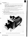
lTA-2.2
Figure 5-1. Assembled Pump (D16A Pump Model Shown)
Remove the oil casing (12) as follows:
a. Unscrew and remove the lower screws (or nuts) and washers that attach the oil casing (12) to the
coupling housing (11) (see Figure 5-1).
b. WARNING: ESPECIALLY FOR THE HEAVIER PUMPS (D30A AND D60A), BE SURE TO
SUPPORT THE OIL CASING WHILE REMOVING THE SCREWS (OR NUTS). OTHERWISE,
THE CASING MAY FALL, RESULTING IN DAMAGE OR INJURY.
While supporting the oil casing, unscrew and remove the upper screws (or nuts) and washers.
c. NOTE: If you plan to reuse the large flat seal (13) that fits between the oil casing and the coupling housing, carefully peel the seal (13) from the oil-casing flange before removing the oil casing
(see Figure 5-2).
Remove the oil casing by sliding it straight back away from the main flange of the coupling housing.
NOTE: If resistance is encountered, strike the front corner of the oil casing (12) with a rubber
hammer to release the oil casing (12) from the coupling housing (11).
8-8
WARNING: THE DISK ON THE MODULE END HAS A SHARP EDGE. FAILURE TO USE CARE WHEN
REMOVING AND HANDLING THE DISK MAY RESULT IN INJURY.
Using a phillips head screwdriver, remove the disk (61) from the shaft (see Figure 5-2).
8-9
16
WARNING: PUMP FLUIDS ARE EXCELLENT LUBRICANTS AND AS SUCH ARE VERY SLIPPERY. BE
CAREFUL WHEN HANDLING THE MODULE SINCE IT CONTAINS LUBRICATING FLUID WHICH COULD
SPILL CAUSING A HAZARD.
TRIVAC "A" Manual, Edition L
.STEP B·9 CONTINUED
Remove the module as follows:
a. Unscrew and remove the lower screws and washers that attach the module to the coupling housing
(11) (see Figure 5-2).
b. WARNING: ESPECIALLY FOR THE HEAVIER PUMPS (D30A AND D60A), BE SURE TO
SUPPORT THE MODULE WHEN REMOVING THE SCREWS. OTHERWISE, THE MODULE
MAY FALL RESULTING IN DAMAGE OR INJURY.
While supporting the module, unscrew and remove the remaining upper screws and washers.
c. Pull the module straight back and away from the coupling housing (11).
B·10
Clean the large flat seal (13) from the coupling housing (11) and/or front end plate (44) (see Figure 5-2).
NOTE: A replacement gasket is supplied with the gasket set and module repair kit.
5-C
DISASSEMBLING THE MODULE
CAUTION: USE CARE WHEN HANDLING THE MODULE TO AVOID BENDING THE LEVER (41) OR CEN·
TRIFUGAL SWITCH (39) (see Figures 5·3 and 5-4).
C·,
Using a large pair of long nose pliers, pull the valve disk (67) and attached brass piston (68) out of the intake
portion of the high vacuum pump cylinder (55) (see Figures 5·3 and -11).
ITA-4.12
Figure 5-2. Module Attached to Coupling Housing (D2A Pump Model Shown)
TRIVAC "A" Manual, Edition L
17
60
52
D2AMODULE
Figure 5-3.
C-2
lTA-4.15
Module, Side View (D2A Pump Model Shown)
CAUTION: IF A PULLER IS USED TO REMOVE THE COUPLING (37), BE CAREFUL TO AVOID DAMAGING THE CENTRIFUGAL SWITCH (39).
Using a small screwdriver, loosen the setscrew that secures the coupling (37) to the shaft. Pull the coupling off
of the shaft (see Figure 5-3).
C-3
Using small diagonal cutting pliers, pull the coupling key (38) from the slot in the shaft (see Figure 5-4).
C-4
Using snap ring pliers, remove the retainer ring (40) from the shaft (see Figure 5-4).
C-5
NOTE:
For use during reassembly, the centrifugal switch end with the split halves faces the coupling (37).
For the D2A, D4A, D8A, and D16A models only, loosen the one or two setscrews that secure the centrifugal
switch (39) to the coupling (37) (see Figure 5-3).
For the D30A, D60A, and D90A pump models only, loosen the setscrew(s) to remove the centrifugal switch (39)
from the shaft rather than from the coupling (37).
C-6
Using a phillips screwdriver, unscrew and remove the two screws that attach the lever to the front end plate~
When removing the lever (41), hold its opposite end down to avoid losing the spring (42) from the penetration
in the front end plate (44). Remove the lever (41) and spring (42) from the plate (44) (see Figure 5-4).
C-7
Using a small screwdriver, remove the retainer disk (71) from the slot in the air inlet (69) tube (see Figure 5-4).
C-8
CAUTION: FAILURE TO HOLD THE DRIFT PIN (or bolt) STRAIGHT WHEN DRIVING THE CYLINDRICAL PINS COULD RESULT IN DAMAGE TO THE MODULE HOUSING.
Using a hammer and a drift pin (or long bolt). remove the cylindrical pins as follows (see Figure 5-5).
a. Drive one of the two short cylindrical pins (64) that aligns 'the rear end plate (60) and the high
vacuum stage pump cylinder (55) toward the center bearing (52) until the pin (64) falls out.
NOTE: On some pump models, this pin (64) does not have room to fall out. In this case, continue driving it until all three pins fall out of the alignment hole in the front end plate (44).
b. While keeping the drift pin (or bolt) inserted through the rear-end-plate alignment hole, drive the
long cylindrical pin (65) toward the front end plate (44). Continue driving the cylindrical pins
18
TRIVAC "A" Manual, Edition L
C8b CONTINUED
until the long pin (65) forces the other short pin (the one that aligns the front end plate (44) and
the second stage pump cylinder) to fall out, and then the long pin also falls out of the front-endplate alignment hole (see Figure 5-5).
c. Repeat Steps C-8a and C-8b for the two short and one long cylindrical pins on the other side of
the module.
55
1TA-4.20
Figure 5-4.
C-9
Front End of Module Minus Coupling and Centrifugal Switch (D2A Pump Model Shown)
Unscrew and remove the hexagon nuts (63) and washers from the ends of the threaded studs (62) which tie the
module segments together (see Figure 5-6).
NOTE: The D8A and 0 16A pump models have four, rather than three, threaded studs and hexagon nuts.
C-10
Remove the rear end plate (60) from the module (see Figure 5-6).
NOTE: If necessary, lightly tap the back edge of the plate with a rubber hammer to free the plate from the
module. This note also applies to Steps C-12, C-13, and C-15.
C-11
CAUTION: DO NOT SCRATCH THE INSIDE SURFACE OF THE PUMP CYLINDER OR THE END OF THE
ROTOR. SCRATCHES ON THESE SURFACES RESULT IN POOR ULTIMATE PRESSURE.
CAUTION: DO NOT CHIP, SCRATCH, OR BREAK THE EDGES OF THE VANES DURING DISASSEMBLY,
IF THEY ARE TO BE REUSED.
NOTE: If you plan to reuse the vanes, be sure to mark the orientation and location of each vane so that during
reassembly each used vane is replaced in its same rotor slot and so that each used vane is not turned end-for-end
in its slot.
REQUIRED ACTION:
(See Figure 5-7).
TRIVAC "A" Manual, Edition L
Using long nose pliers, remove the three vanes (53) from the high vacuum rotor (54).
19
Figure 5-5.
Removing the Cylindrical Pins From the
Module (D2A Pump Model Shown)
Figure 5-6.
Rear End of Module Minus the Disk
(D2A Pump Model Shown)
C·12
Remove the high vacuum stage pump cylinder (55) to expose the high vacuum rotor (54) and the center bearing
(52). Remove the O-rings (47) from both sides of this pump cylinder (see Figure 5.7).
C-13
Remove the front end plate (44) from the motor side of the shaft (see Figure 5-8).
C-14
Pull the air inlet tube (69) from the front end plate (44) or high vacuum stage pump cylinder (55).
5-3 and 5-8.)
C-15
Remove the second stage pump cylinder (46) to expose the second stage rotor (48).
from both sides of this cylinder (see Figure 5-8).
C-16
Repeat Step C-", except remove the vanes (49) from the second stage rotor (48). (See Figure 5-8).
C-17
CAUTION: BE CAREFUL TO AVOID SCRATCHING THE END OF THE ROTOR OR THE CENTER BEA
ING. SCRATCHES TO THESE SURFACES RESULT IN POOR PUMP PERFORMANCE.
REQUIRED ACTION: Using a puller or a prying device, remove the high vacuum stage rotor (54) from the
NOTE: Two threaded metric pulling holes are located in the outside end of the high vacuum rotor (54) for
with a puller (see Figure 5-7).
NOTE; The second stage rotor (48) and the shaft are permanently attached to each other on the D2A. D4A.
and D16A pump models.
C-18
Using small diagonal cutting pliers, pull the high-vacuum-stage rotor key (57) from the slot in the shaft
Figure 5-9).
C-19
Slide the center bearing (52) off of the shaft (see Figure 5-9).
20
TRIVAC "A" Manual,
Ed'iti(jtn
tTA-4.27
Figure 5-7.
Figure 5-8.
TRIVAC "A" Manual, Edition L
High Vacuum (HV) Stage Pump
Cylinder (D2A Pump Model Shown)
Second Stage Pump Cylinder (D2A Pump Model Shown)
21
,.,Acc HOLE nlAT
. f'ACESAWAVFI'lOM
.I11iC::OND STAGERQTOR
tTA·5.19A
Figure 5-9.
5-D
D-1
High Vacuum Stage Rotor Removed From the Shaft (D2A Pump Model Shown)
DISASSEMBLING THE REMAINING PARTS
WARNING: DaAlAC THROUGH D90AlAC EXTREME-CORROSIVE SERVICE PUMPS HAVE AN ADAPTER EPOX-,'
lED TO THE TOP OF THE GAS BALLAST VALVE (SEE SKETCH 2-1). DO NOT REMOVE THIS ADAPTER OR
DO STEP f FOR THESE PUMP MODELS. THE GAS BALLAST VALVE IS INTENTIONALLY PLUGGED ON
AND D4A EXTREME-CORROSIVE SERVICE PUMPS; THEREFORE, DO NOT DO STEPS a, d, e, AND f FOR
PUMPS WITH INTENTIONALLY PLUGGED GAS BALLAST VALVES.
Disassemble the gas ballast valve as follows:
a. For all pump models, pull the cap (18) off of the gas ballast valve (17). (See Figure 5-10A.)
b. For the DBA and D16A pump models only, use snap ring pliers to remove the retainer ring (34)
from the gas ballast valve tube (17), then slide the cover (33) off of the tube (17).
c. For all pump models, slide the O-ring (27), flat gasket (29), and spring (28) off of the gas ballast
valve (17) tube (see Figure 5·10B).
d. For the D2A and D4A pump models only, use a screwdriver to unscrew and remove the nonreturn
valve (23) assembly from inside of the top of the gas ballast valve (see Figure 5-10A).
e. For the D2A and D4A pump models only, use a small screwdriver to unscrew and remove the
strengthening piece (26), spring (25), and flat gasket (24) from the nonreturn valve (23). (See
Figure 5-10A).
f. For D8A, D16A, D30A, D60A, and D90A pump models only, use a screwdriver to remove the
retaining washer (21), valve (19), and O-ring (20) from inside of the top of the gas ballast
valve (See Figure 5-1 OA).
g. For the D30A, D60A, and D90A pump models only, remove the retainer ring (30), valve plate
washer (32), spring (31), and valve plate (32) from the tube end of the gas ballast valve (See
Figure 5-10B).
0-2
Remove the two O·rings (70) from the air inlet tube (69). (See Figure 5-11.)
D·3
Remove the O-ring (3) from the dirt trap (2). (See Figure 5-11.)
D-4
Remove the O-ring (5) from the end of the pump intake tube (1). (See Figure 5-11.)
0-5
For D2A, D4A, DBA, and D16A pump models, pull the brass piston (68) from the valve disk (67). (See
5·11.)
For D30A, D60A, and D90A pump models, unscrew the brass piston (68) from the valve disk (67). (See
5-11.)
D·6
Remove the flat gasket (9) from each of the two plug screws (8). (See Figure 5-11.)
22
TRIVAC "A" Manual, Edition
02AiD4A
VALVE ASSEMBLY
ITA-3.3
NOTE: The tube end of the D8A/D16A gas ballast valve is similar to the D2A/D4A, except the D8A/D16A
has a cover (33) and retainer ring (34) above the oil filter (35).
Figure 5-1 DB. Tube End of Gas Ballast Valve
TRIVAC "A" Manual, Edition L
23
NOTE; A" parts shown are from a D2A pump model, except for the D30A/D60A/D90A coupling ring (36).
Figure 5·11. Miscellaneous Disassembled Parts
0·7
Remove the seal (43) from the lever (41). (See Figure 5·11.)
CAUTION: BE CAREFUL TO AVOID SCRATCHING THE END PLATE OR INSIDE OF THE BRONZE
BUSHING WHEN REMOVING THE RADIAL SHAFT SEAL. SCRATCHES TO THESE SURFACES COULD
RESULT IN POOR PUMP PERFORMANCE.
Remove the radial shaft seal (45) from the rear end plate (60) as follows (see Figure 5·12).
a. Place a thin wooden block on/or beside the end plate.
b. CAUTION: DO NOT INSERT ANY TYPE OF PRYING DEVICE INTO OR THROUGH THE
BRONZE BUSHING.
Insert the end of a screwdriver between the bronze bushing and the shaft seal (45). Rest the shaft
of the screwdriver on the wooden block.
c. Using the wooden block as a fulcrum and the screwdriver as a lever, pry the shaft seal (45) out of
the end plate.
Unscrew and remove the threaded studs (62) from the front end plate (44). (See Figure 5·12.)
NOTE: The D8A and 0 16A pump models have four threaded studs, rather than three.
NOTE: For use during reassembly, the ends of the threaded studs (62) that have the shorter threaded
screw into the front end plate (44) (see Figure 5·8). During reassembly, the threaded studs should be screwed
they are tight in the front end plate.
Repeat Step 0·8, except remove the shaft
se~1
(45) from the front end plate (44).
For the D4A, OlGA, D60A, and D90A pump models only, use an allen wrench to remove the two screws
attach the retaining bracket (59) to the high vacuum pump cylinder (55). Remove the retaining bracket
valve plate (58) from the pump cylinder (see Figure 5·13).
NOTE:
The D2A, D8A, and D30A pump models do not have retaining brackets (59) and valve plates
TRIVAC "A" Manual, Edition
...;..--60
1TA·7.5
Figure 5-12. Removing the Radial Shaft Seal From the End Plates (D2A Pump Model Shown)
NOTE: The D60A and D90A pump model has two retaining brackets (59) and two valve plates (58) that must be
removed.
NOTE: For use during reassembly, the thicker viton section of the valve plate (58) faces up.
D-12
NOTE: When removing the valve stop (51), observe the orientation of the valve stop, valve plate (50), and pump
cylinder (46). It is important that these parts are placed in this same orientation during reassembly (see Figure
5-14).
Unscrew and remove the four screws that attach the valve stop (51) to the top of the second stage pump cylinder
(46). Remove the valve stop (51) and thin metal valve plate (50) from the pump cylinder (46). (See Figure 5-14.)
NOTE: The valve stops (51) on the larger pumps are cast aluminum. On most of the smaller pumps, the valve
stops are a black plastic.
67168
1TA-3.14A
Figure 5-13. D4A Module Showing Retaining Bracket and Valve Plate
TRIVAC "A" Manual, Edition L
25
VALVE STOP
(1)1)
VALVE PLATE
(501
SECOND STAGE
PUMP CYLINDER
(461
'I
I
[I
OIL NOZZLE
(561
ITA·7.9
NOTE: The valve plate (50) on the D30A/D60A/D90A pump models has four tabs rather than two.
Figure 5-14. Removing the Valve Stop and Plate (D2A Pump Model Shown)
0-13
Using a U.S. standard wrench, unscrew and remove the four nuts and washers that attach the motor (73) to
the coupling housing (11). Remove the motor from the coupling housing (see Figure 5-15).
0-14
For the D2A, D4A, DBA, and D16A pump models only, pull the elastic element (36) off of the coupling (37)
mounted on the motor shaft (see Figure 5-15).
For the D30A, D60A, and D90A pump models only, pull the coupling ring (36) off of the coupling (37) mounted
on the motor shaft (see Figures 5-11, 5-3, and 5-15).
0·15 CAUTION: DO NOT USE CHANNEL LOCK PLIERS TO REMOVE THE OIL LEVEL GLASS ASSEMBLY
FROM THE COUPLING HOUSING. USING CHANNEL LOCKS COULD RESULT IN DAMAGE TO THE 01 L
LEVEL GLASS ASSEMBLY.
11
lTA·3.16
D30A/D60A
COUPLING AND
COUPLING RING
Figure 5·15. Coupling Housing and Motor (D2A Pump Model Shown)
26
TRIVAC "A" Manual, Edition L
0·15 CONTINUED
If necessary for cleaning, remove and disassemble the oil level glass assembly (15) as follows:
a. Use one of the following three methods to remove the oil level glass assembly from the coupl ing
housing (11).
Method (1) - Unscrew the assembly using an adjustable spanner which has the correct pin locations to match the two holes in the assembly.
or
Method (2) - Place the nose ends of a large pair of snap ring pliers into the two holes in the assembly (15); insert a screwdriver or small bar between the nose ends of the snap ring pliers; use the
screwdriver or bar to force the pliers and the assembly to turn counterclockwise; unscrew the
assembly from the coupling hOUsing (see Figure 5-16).
or
Method (3) - Place a sturdy pin, drift pin, or drill bit into each of the two holes in the assembly
(15); cross the pins to form an "X"; insert a screwdriver or small bar through the oil-Ievel-glassassembly side of the "X"; use the screwdriver or bar to force the pins and the assembly to turn
counterclockwise; unscrew the assembly (15) from the coupling housing (11).
b. Disassemble the oil level glass assembly (15) as follows:
5-E
(1)
Using long nose pliers, unscrew the target piece from the assembly.
(2)
Push the glass and gaskets out of the assembly.
CLEANING AND INSPECTING THE DISASSEMBLED PUMP
CAUTION: THE SECTION 5-E INSTRUCTIONS ARE FOR CLEANING PUMP PARTS. DO NOT USE THESE
INSTRUCTIONS FOR CLEANING THE MOTOR.
It is not necessary to clean parts that will not be reused. A new valve disk (67) and elastic element (36), and all new
seals, gaskets, and O-rings should be used for all pumps.
Use Freon TF or acetone to clean all surfaces thoroughly. For final rinse, use solvents such as alcohol or Freon TF.
lTA-3.33
Figure 5-16. Removing the Oil Level Glass (15) From the Coupling Housing (D2A Pump Model Shown)
TRIVAC "A" Manual, Edition L
27
5-E-1
Special Requirements for extreme-Corrosive Service Pumps
WARNING: STEPS 1 THROUGH 4 BELOW MUST BE FOLLOWED FOR EXTREME-CORROSIVE
SERVICE PUMPS.
1. NOTE: New vanes (49/53) and a new oil filter (35) are required for extreme-corrosive service pumps;
therefore, it is not necessary to do Step E-8c.
REQUIRED ACTION: Refer to Steps E-' through E-8b(2) to clean and inspect all metal parts.
2. Degrease all tools that will be used for handling degreased extreme-corrosive service pump parts.
Ensure that the working surface is free of any hydrocarbon substance.
3. Degrease and rinse all metal pump parts in a nonhydrocarbon solvent.
4. Wet all seals and all internal pump parts with the recommended perfluoropolyether pump fluid.
5-E-2
Instructions for Cleaning and Inspecting All Pump Models
Give particular attention to cleaning the following areas.
E-l. Inspect all a-ring grooves for burrs and dirt. Sand and/or clean as necessary.
E-2. CAUTION: FAILURE TO REMOVE BURRS AND SCRATCHES FROM THE SHAFT COULD
RESULT IN DAMAGE TO THE RADIAL SHAFT SEALS (45).
Inspect the coupling key (38) and the shaft for burrs or scratches. Sand smooth, if necessary (see
Figure 5-4).
E-3. Ensure that all dirt accumulation is cleaned from all passages, including the following:
a. The hole on the bottom edge of the front end plate (44) - this hole extends all the way
to the bronze bushing.
b. The small hole in or just above the rear-end-plate (60) and front-end·plate (44) bronze
bushing (see Figures 5-6 and 5-8).
c. The oil nozzle (56) hole in the second stage pump cylinder (46) - remove the oil nozzle
screw and clean the screw and the hole (see Figure 5·14); then screw the oil nozzle (56)
into its hole in the cylinder (46).
NOTE: The D30A, D60A, and D90A pump models have two oil nozzles that must be
cleaned.
d. For D30A, D60A, and D90A pump models only, clean the brass air nozzle screw (66)
located inside of the intake tube portion of the high vacuum pump cylinder (55).
e. The tiny Silencing hole in the side of the gas ballast valve (17) stem just below
the bolting flange - use fine wire to clear any dirt from the hole; DO NOT
ENLARGE THE HOLE.
E-4. Using a brush, thoroughly clean the center bearing (52). (See Figure 5-9.)
E-5. Clean all dirt accumulation or buildup from the three vane slots in each rotor (48/54).
Figure 5-9.)
(See
E-6. Visually inspect the air inlet tube (69) to ensure that it is clear of debris (see Figure 5-11).
28
TRIVAC "A II Manual, Edition L
E-7 _ Thoroughly clean the coupling housing (11 L making certain that no dirt has accumulated in the
crevices of the housing (see Figure 5-15).
E-S. Carefully inspect all parts for excessive wear. Give particular attention to the following:
a. The ends of each rotor (48/54) may be wearing against the inside surface of the front
(44) and rear (60) end plates or against the center bearing (52). Inspect these surfaces
for gouges and wear (see Figure 5-S). If you observe scoring or wear, proceed as follows:
( 1)
Replace the plate that is scored.
(2)
Check the rotors for burrs.
(3)
Using calipers or micrometers, measure the length of each rotor (Dimension A
of Figure 5-9). If the length dimension of either rotor is less than the dimension listed for your pump model in Table 5-1 (on the following page), replace
that rotor.
If burrs are found, sand or file them smooth.
b. The shaft rides in bronze bushings in the front (44) and rear (60) end plates and in the
center bearing (52) plate (see Figures 5-6, 5-8, and 5-9). Inspect the inside surface of
these three bronze bushings for gouging or wear. If you observe deep gouging, replace the
gouged shaft or the plate containing the gouged bushing_ If you observe minor scratches
or wear, proceed as follows:
(1)
Using calipers or micrometers, measure the inside diameter (I D) of the bronze
bushing_ If the lOis greater than the dimension listed for your pump in
Table 5-1, replace the end plate or center bearing plate containing the worn
bushing.
(2)
Using calipers, measure the outside diameter (00) of the shaft at each area of
wear. If the shaft 00 at any point of wear is less than the dimension listed
for your pump model in Table 5-1, replace the shaft.
c. Three rectangular vanes (49/53) fit into slots in each rotor (48/54). (See Figures 5-7 and
5-8.) Using calipers or micrometers, measure the length and thickness dimension of each
vane. If either dimension is greater than the maximum or less than the minimum dimension listed for your pump model in Table 5-1, replace that vane. If a vane dimension is
greater than the maximum, it is the result of swelling due to chemical attack.
E-9. Using a paint brush, cover all the pump parts with a light coat of the proper pump fluid. (see Section
5-A-1).
5-F
REASSEMBLING THE PUMP
New seals, gaskets, and O-rings and a new valve disk (67) and elastic element (36) should be used when reassembling the pump. Use a new valve plate (50) only if wear is visible on the old valve plate. For extreme-corrosive
service pumps, new vanes (49/53) and a new oil filter (35) are also used.
Wet the O-rings, gaskets, and seals with a film of the proper pump fluid before installing. Make certain that all 0rings, gaskets, seals, and all pump parts are clean before reassembly.
F-1
CAUTION: IF THE PUMP ROTATES IN THE WRONG DIRECTION FOR TOO LONG, PUMP FLUID IS EJECTED
OUT OF THE INTAKE TUBE (1) AND THE VALVE DISK (67) OR THE MOTOR MAY BE DAMAGED.
Ensure that the direction of rotation of the motor is correct as follows:
a. Steps a(1) and a(2) are for the D30A pump models with single-phase motors and for all D2A, D4A,
DBA, and D16A pump models:
See plate on motor for motor specifications.
TRIVAC "A" Manual, Edition L
29
E 5-1. ROTOR, BEARING, SHAFT, AND VANE CRITICAL DIMENSIONS
Minimum
Rotor
Length
(mm)
Maximum
Bushing
Diameters
(mm)
D2A
D4A
D8A
D16A
D30A
D60A/D90A
Sa
34.970
34.970
44.960
44.960
74.921
74.921
HV a
34.970
69.970
44.960
89.960
74.921
149.890
Fb
12.027
12.027
15.027
15.027
22.033
22.033
Cb
12.027
12.027
15.043
15.043
22.070
22.070
Rb
12.027
12.027
15.027
15.027
22.033
22.033
11.992
11.992
14.992
14.992
21.991
21.991
34.991
34.991
44.991
44.991
74.990
74.990
54.830
54.830
78.630
78.630
118.535
118.535
Minimum Shaft
Diameter at
Points of Wear
(mm)
Second Stage
Vane
Dimensions
(mm)
TCmin.
High Vacuum
Stage Vane
Dimensions
(mm)
TC
LC
max.
Maximum Inside
Diameter d of Pump
Cylinders (mm)
abcdStep F·l (a) (Cont'd.)
= second stage pump cylinder; HV = high vacuum stage pump cylinder.
= front bushing; C = center bushing; R = rear bushing.
length; T = thickness; max. = maximum; min. = mrnimum.
S
F
L :;
See
Figure 5·7.
a(1) If the motor is single phase !ill! it was supplied through Leybold, it has been factory
wired for correct rotation; therefore, it isn't necessary to check motor rotation unless you
altered the wiring or replaced the motor. If the wiring was altered or the motor replaced, refer
to Step a(2) below.
a(2) If the motor Is 3-phase, or if it wasn't supplied through Leybold, or if its wiring was
altered, check the direction of rotation as follows:
A
(a) Connect the power supply momentarily to jog the motor, and then immediately switch it oft
'k!:
"I
1:1,
"
30
TRIVAC "A Manual, Edition L
II
Step a(2) (Cont'd)
(h)
Check if the fan on the rear end of the motor is rotating in the correct direc·
tion. Looking from the fan end of the motor, the fan and motor shaft should
be rotating clockwise (see Figure 5· 15).
(c)
Turn off the motor and disconnect the power supply.
(d)
If the rotation direction is incorrect, reverse it by interchanging the electrical
line connection at the motor end, then repeat Steps a(2) (a) through a(2) (c)
above. For 3·phase motors, correct the direction of rotation by interchanging
any two of the three phases.
b. Steps b(1) and b(2) below apply only to D30A, D60A, and D90A pump models with three
phase motors.
(1) If the pump has a new motor supplied by Leybold, a rotational lock bearing has
been correctly installed at the factory to prevent the motor from rotating in the wrong
direction. In this case, check the wiring of the motor as follows:
CAUTION: FAILURE TO IMMEDIATELY TURN OFF THE MOTOR IF THE MO·
TOR FAN DOES NOT ROTATE COULD RESULT IN DAMAGE TO THE MOTOR
AND THE PUMP.
(a)
Connect the power supply and turn the motor on.
(b)
Check if the fan on the rear end of the motor (see Figure 5· 15) rotates.
(c)
Turn off the motor and disconnect the power supply.
(d)
If the fan did not rotate, correct the motor wiring by interchanging any two
of the three phases; then repeat Steps b(1) (a) through b(1) (c).
(2) If the motor was not supplied through Leybold or the pump has an old Leybold
supplied motor, grab the motor shaft or motor fan and attempt to turn it clock·
wise and then counterclockwise; then proceed as follows:
CORRECTLY INSTALLED LOCK BEARING
Looking from the fan end of the motor, if the fan or shaft will turn clockwise and will
not turn counterclockwise, the pump has a correctly installed rotational lock bearing.
In this case, do Steps b(1) (al through b(1l (dl to check the wiring.
LOCK BEARING INSTALLED BACKWARDS
Looking from the fan end of the motor, if the fan or shaft will turn counterclockwise
and will not turn clockwise, the rotational lock bearing is installed backwards. In this
case, do Steps b(2) (a) through b(2) (s), which follow, to disassemble the motor and
install the lock bearing correctly.
NO LOCK BEARING OR MALFUNCTIONING LOCK BEARING
If the fan or shaft will rotate in both directions, we recommend installing a rotational
lock bearing. (See Steps b(2) (a) through b(2) (s).) If you have insufficient time to
order and install a rotational lock bearing now, do Steps a(2J (a) through a(2) (d) to
ensure correct rotation of the motor; then order and install a rotational lock bearing as
soon as possible.
Proceed as follows to install a rotational lock bearing (see Figure 5-17). Note that the rotational lock bearing is installed on the fan end of the motor for all pump models except
for D60A/D90A pump models with Marathon motors. The lock bearing on D60AID90A's
with Marathon motors is installed on the shaft end.
NOTE:
Catalog numbers for the required parts and materials are listed in Table 5·2.
NOTE: If the motor is attached to the pump, remove the motor before proceeding
with Steps (a) through (s).
(a)
TRIVAC ''A II Manual, Edition L
Unscrew and remove the screws that attach the fan cover to the end of the
motor. Remove the fan cover.
31
Step F-1 b (2) (Cont'd.)
(b)
For D30A pump models, use an allen wrench to loosen the setscrews that
secure the fan to the shaft. Remove the fan.
For D60A and D90A pump models, loosen the screw that secures the fan to
the shaft. Remove the fan; then use diagonal cutting pliers to remove the key
from the shaft.
NOTE: For use during reassembly, the fan must be positioned on the shaft
so that it does not contact the fan end-plate or the fan cover.
TABLE 5-2. Parts Required for Installing the Rotational Lock Bearing
Pump
Model
D30A
Quantity
Part Name
Part Number
1
Rotational Lock Bearing KK17
991040045
2
Spring Washer
72534002
Loctite 601
D60ND90A
1
Rotational Lock Bearing KK35 for
Marathon Motors*
721 12005*
1
Rotational Lock Bearing KK30 for
GEMotors
721 12004
2
Spring Washers K 6206 for GE Motors
99164002
Loctite 601 or 609
*For D60A and D90A pumps that have Marathon motors, the rotational lock bearing goes onto the shaft
end of the motor, not on the fan end.
Figure 5-17. Disassembled Motor (D30A Motor Shown)
32
TRIVAC "A" Manual, Edition L
Step F-lb (2) (Cont'd.)
(c)
Unscrew and remove the four hex head bolts that attach the fan end-plate
to the motor. Use a hammer to tap the edge of the fan end-plate to remove
it from the motor.
NOTE: If the motor has a malfunctioning rotational lock bearing, it will be
nElcessary to use a torch to heat the center of the fan end-plate and the shaft.
The heat should help loosen the Loctite 609 which bonds the OD of the
rotational lock bearing to the fan-end-plate bearing well. The lock bearing
is press fit and bonded to the shaft with Loctite. Additional heat may be
required to separate the lock bearing from the shaft.
(d)
Except for D60A/D90A's with Marathon motors, remove and discard the three
spring washers that fit between the fan end-plate and the bearing.
(e)
Remove the shaft and attached rotor from the motor housing.
NOTE: It may be necessary to tap the other end of the shaft to free the shaft
from the other end-plate.
For D30A pump models only, remove and save for reassembly the two spacer
rings that fit into the fan-end-plate bearing well. Remove and discard the
spacer ring that fits against the bearing on the other end of the shaft.
Grease the two new spring washers (see Table 5-2) and place them together so
that the IDs are tight against each other and so that there is a gap between the
ODs. (Figure 5-17 shows ungreased spring washers placed together as described above.)
(f)
(g)
(h)
Except for the D60A/D90A's with Marathon motors, reach through the motor
housing to place the two new greased spring washers into the bearing well in
the other end plate.
(i)
Except for the D60A/D90A's with Marathon motors, use a puller to remove and
discard the fan-end bearing from the shaft.
NOTE: The fan-end bearing is the smaller bearing.
(j)
CAUTION: IF ALL GREASE IS NOT REMOVED FROM THE MATING
SURFACES, THE LOCTITE WILL NOT FORM A PERMANENT BOND
AND THE ROTATIONAL LOCK BEARING WILL NOT WORK. THE BEST
SOLVENT FOR THIS PURPOSE IS TRICHLOROETHANE. THE FOLLOWING SOLVENTS SHOULD NOT BE USED, SINCE THEY LEAVE A FILM
ON THE SURFACE: KEROSENE, GASOLINE, NAPTHA, FUEL OIL,
VARSOL, AND STODDARD SOLVENTS.
CAUTION: DO NOT IMMERSE THE NEW ROTATIONAL LOCK BEARING IN SOLVENT. GREASE MUST REMAIN IN THE INSIDE OF THIS
BEARING.
Wipe all grease from the bearing well in the fan end-plate, from the fan end
of the shaft, and from the 10 and 00 of the new rotational lock bearing.
(k)
Reinstall the rotor and shaft in the motor housing.
NOTE: When installed properly, the fan end of the shaft (the one with the
bearing removed) will face you.
(I)
CAUTION: It is essential that the rotational lock bearing is placed on the shaft
in a way which allows the Inner Bearing Sleeve to rotate clockwise. Except for
the D60A/D90A's with Marathon motors, the side of the bearing that has the
bearing's name and number stamped in it should face toward the center of the
motor. Occasionally, the name and number are stamped on the wrong side of
this bearing. To double check, hold the 00 of the rotational lock bearing so that
the side with the stamped name and number faces the rotor. While holding the
OD tight, rotate the 10. If the 10 rotates only in the clockwise direction, the
rotational lock bearing is positioned correctly.
TRIVAC "A" Manual, Edition L
33
Step F-l (b) (2) (Cont'd.)
(m)
CAUTION: FAILURE TO EVENLY DRIVE THE ROTATIONAL LOCK
BEARING DOWN THE SHAFT COULD RESULT IN GALLING OF THE
BEARING ID.
REQUIRED ACTION: Apply Loctite 609 to the area of the shaft where the
bearing will fit and to the 10 of the new rotational lock bearing. USing a hammer and
a pipe that has an 10 greater than the shaft 00, gently tap the rotational lock bearing down over the shaft until it bottom$, out. Wipe off any excess Loctite.
(n)
CAUTION: It takes about 5 minutes for loctite 609 to begin setting. For
D30A pump models, Steps (0) and (p) should be completed before the Loctite has time to set, in case the end plate must be removed.
Apply Loctite 609 to the 00 of the new rotational lock bearing and to the 10
of the mating bearing well in the end plate.
(0)
Repeat Steps (f), (c), and (b), except assemble rather than disassemble.
(p)
For D30A pump models only, spin the fan to check if the motor rotates
freely. If there is a lot of friction, immediately remove the fan and the fan
end-plate before the Loctite has time to set; then remove and discard one of
the spacer rings and reassemble the motor.
(q)
Using the four screws, attach the fan cover to the motor.
(r)
Spin the shaft to check if the fan contacts the fan cover or fan end-plate.
If it does, remove the fan cover and adjust the position of the fan on the
shaft; then reassemble.
(s)
NOTE: Allow the motor to sit for at least 1 Y:, hours prior to testing. This
will allow the locktite time to cure and firmly bind the surfaces.
REQUIRED ACTIONS: Use the instructions at the beginning of Step b(2) to
determine if the rotational lock bearing is installed correctly and to correct
the problem if the lock bearing is installed backwards or is malfunctioning.
If the lock bearing is installed correctly, repeat Steps b(l) (a) through b(l)
(d) to check the wiring of the motor.
F-2
NOTE: When reassembling the valve plate (50) to the second stage pump cylinder (46), ensure that the bent
tabs that cover the exhaust holes are facing down. If the tabs are not bent, it does not matter which side is faCing
down.
Repeat Steps 0-15 through 0-11, 0-9, and D-7 through 0-2, except assemble rather than disassemble.
F-3
CAUTION: NICKS OR TEARS IN THE RADIAL SHAFT SEAL COULD RESULT IN A LUBRICATING
FLUID LEAK AND POOR PUMP PERFORMANCE.
CAUTION: FAILURE TO RECESS THE RADIAL SHAFT SEAL (45) IN ITS SLOT IN THE REAR END
PLATE (60) WILL RESULT IN THE VANES (53) RUBBING AGAINST THE SEAL (45) DURING PUMP
OPERATION.
NOTE: The side of the seal that has a small circular spring around the 10 faces the bronze bushing in the rear
end plate (60).
REQUIRED ACTION: Use one of the following methods to install a new radial shaft seal (45) in the rear end
plate (60) (see Figure 5-12).
Method (1) - Insert the new seal into its slot in the rear end plate. Using a hammer and a seal driver (see Figure
5-22), recess the seal in the slot.
or
Method (2) - Insert the new seal into its slot in the rear end plate. Place the used seal over the new seal. Use a
hammer to tap the used seal until it indents the new seal in its slot in the rear end plate. Remove and discard the
used seal.
34
TRIVAC "A II Manual, Edition L
F-4
Assemble the gas ballast valve (20) as follows:
a. For D8A, D16A, D30A, D60A, and D90A pump models only, reassemble the insides of the cap
end of the gas ballast valve (17) as follows (see Figure 5-1 OA).
(1) Fit the a-ring (20) around the inner rim of the valve plate (19). The a-ring goes onto
the side of the valve plate that has the metal valve.
(2) Insert the valve plate (19)/a-ring (20) assembly into the top of the gas ballast valve (17).
The side of the valve plate that has the metal valve faces down.
(3) Push the retaining washer (21) into the top of the gas ballast valve until it is tight against
the valve plate (19).
b. For D30A, D60A, and D90A pump models only, insert the parts into the inside of the tube end
of the gas ballast valve in the following order (see Figure 5-10B).
First
Second
Third
Fourth
-
Valve plate (32) that has three slots.
Spring (31).
Valve plate (32) washer.
Retainer ring (30). Fit the retainer ring into the groove in the inside of the gas
ballast valve tube.
c. Repeat Steps D-l e through D-l a, except assemble rather than disassemble.
F-5
Assemble the high vacuum stage rotor (54) and the center bearing (52) to the shaft as follows (see Figures 5-9
and 5-181.
a. NOTE: The second stage rotor (4B) is permanently attached to the shaft on the D2A, D4A, DBA,
and D16A pump models.
NOTE: If the center bearing plate (52) does not have the small hole, it can face either direction.
Coat the bronze bushing with the proper pump fluid and slide the center bearing (52) onto the
shaft so that the side of the center bearing (52) with the small hole faces away from the second
stage rotor (48) (see Figure 5-9).
b. Insert the rotor key (57) into its slot in the shaft. Tap the key (57) down into its slot.
c. NOTE: The end of the high vacuum stage rotor (54) with the two pulling holes is the outside end.
Align the slot in the ID of the high vacuum stage rotor (54) with the rotor key (57) in the shaft.
Slide the rotor (54) onto the shaft. The rotor (54) must slide freely on the shaft.
CENTER
BEARING
PLATE
(52)
r '.
\
SECOND STAGE
ROTOR
HIGH VACUUM
STAGE ROTOR
(48)
(54)
lTA·7.13
Figure 5-1B. Rotors/Shaft/Center Bearing Plate Assembly (D2A Pump Model Shown)
TRIVAC ''A'' Manual, Edition L
35
F-6
CAUTION: FAILURE TO ENSURE THAT THE O-RINGS (47) REMAIN IN THEIR GROOVES DURING
MODULE ASSEMBLY WILL RESULT IN DAMAGE TO THE O-RINGS AND POOR PUMP PERFORMANCE.
NOTE: The module assembly sequence (Steps F-6a through F-6j) is designed to keep the loose O-ring facing uP.
so that it does not fall out of its O-ring groove.
CAUTION: WHEN ASSEMBLING THE MODULE. DO NOT SCRATCH THE ENDS OF THE ROTORS OR
THE INSIDE SURFACES OF THE PUMP CYLINDERS OR END PLATES. SCRATCHES TO THESE SURFACES COULD RESULT IN POOR PUMP PERFORMANCE.
NOTE: To ensure that each part is oriented correctly. refer to Figure 5-3 and follow each step precisely (Steps
F-6a through F-6j).
REQUIRED ACTION: Assemble the module as follows:
a. Place the high vacuum (HV) stage cylinder (55) so that it is lying flat with the intake tube portion
(the top) on the right facing away from you (see Figure 5-19). Fit an O-ring (47) into the O-ring
groove on the cylinder (55) surface that is facing uP.
b. Attach the assembly that you put together in Step F-5 to the HV stage pump cylinder (55) as
follows:
Figure 5-19. Driving the Long Cylindrical Pins that Align the HV Cylinder and the
Center Bearing (D2A Pump Model Shown)
TRIVAC "A" Manual, Edition L
b (Cont'd.)
(1) Take the Step F-5 assembly and insert its HV-stage end (the end that has two pulling
holes on the outside end of the rotor) down into the HV stage cylinder (55) until the
center bearing plate (52) rests against the HV stage cylinder (55) (see Figure 5-19).
(2) Align the two alignment holes in the center bearing plate (52) with the two upper alignment holes on the HV stage cylinder (55). (See Figure 5-19).
(3) NOTE: When driving the two long cylindrical pins (65) into the alignment holes, the
flat end (nonbeveled end) of the pins (65) should face the HV cylinder (55). The HV
cylinder is the one with the intake tube portion.
REQUIRED ACTION: Using a rubber hammer, hit the beveled end of the pins to drive
the two long cylindrical pins (65) down through the two alignment holes in the center
bearing plate (52), then through the two upper alignment holes in the HV cylinder (55)
until the flat end of each pin extends just out of each upper HV-cylinder alignment hole
(see Figure 5-19).
(4) Ensure that the center bearing plate (52) and the HV stage cylinder (55) are tight
against each other and that they remain tight throughout the module assembly sequence.
c. Place the second stage pump cylinder (46) so that it is lying flat with the top edge (the flat portion
that has the screw holes, exhaust holes, and gas ballast hole) on the right facing away from you.
Fit an D-ring (47) into the D-ring groove on the cylinder (46) surface that is facing up.
For D30A, D60A, and D90A pump models, the second stage cylinder (46) should be lying flat on
an open vice or other open support, so that the shaft can be inserted through it in Step d(3).
d. Attach the assembly that you put together in Step b(3) to the second stage pump cylinder as
follows (see Figure 5-20):
(1) Take the assembly from Step b(3) and insert its second-stage end (the end that has the
longer section of the shaft) down into the second stage pump cylinder (46).
(2) NOTE: When aligned correctly, the flat portions of the top of the two pump cylinders
\(46/55) are in line with each other.
REQUIRED ACTION: Align the beveled end ofthe two long cylindrical pins (65) (the
pins which extend out of the alignment holes in the center bearing plate (52)) with the
two upper alignment holes in the second stage cylinder (46).
(3) NOTE: When Step d(3) is completed, the beveled ends of the two long cylindrical pins
(65) should extend most of the way through the upper alignment holes in the second
stage pump cylinder (46).
REQUIRED ACTION: For the D2A, D4A, D8A, and D16A pump models, while keeping the assembly vertical, pull the second stage cylinder (46) straight up over the long
cylindrical pins (65) until it is tight against the center bearing plate (52) (see Figure
5-20).
For the D30A, D60A, and D90A pump models only, while keeping the assembly
vertical, push the Step b(3) assembly straight down until it is tight against the second
stage cylinder (46).
(4) Ensure that the cylinders (46/55) and center bearing plate (52) remain tight against
each other throughout the module assembly sequence.
e. NOTE: If you are reusing the old vanes (53), make sure that each used vane is replaced in its same
rotor slot. Also make sure that the orientation of each vane is the same as it was before disassembly so that each used vane is not turned end-far-end in its slot.
NOTE: Be sure that the slotted edge of the vanes (53) faces the center of the rotor (54) when inserting
the vanes into the rotor.
.
NOTE: For the D4A, D16A, D60A, and D90A pump models only, the high vacuum stage rotor
(54) and vanes (53) are longer than the second stage rotor (48) and vanes (49). For these pump
models, be sure to insert the longer vanes (53) into the high vacuum stage rotor (54).
TRIVAC "A" Manual, Edition L
37
Figure 5-20. Pulling the Second Stage Pump Cylinder Tight Against th,e
Center Bearing (D2A Pump Model Shown)
Step F-6 e (Cont'd.)
REQUIRED ACTION: Repeat Step C-11, except assemble rather than disassemble, to insert the
three vanes (53) into the slots in the high vacuum stage rotor (54).
f. While keeping the partially assembled module vertical, fit an a-ring (47) into the a-ring groove on
the HV-cylinder (55) surface that is facing up (see Figure 5-20).
g. Attach the rear end plate (60) to the partially assembled module as follows:
(1) NOTE: Be sure to attach the rear end plate (60) to the HV-stage end of the module.
The HV pump cylinder (55) is the one with the intake tube portion.
NOTE: The side of the rear end plate (60) that has the bronze bushing faces out.
REQUIRED ACTION: While keeping the partial1y assembled module vertical, align the
rear-end-plate bushing hole with the shaft. Slide the rear end plate (60) down over the
shaft until the machined surface of the rear 'end plate fits tight against the HV stage
cylinder (55).
(2) Align the two alignment holes in the rear end plate (60) with the two alignment holes
in the HV cylinder (55), then use a rubber hammer to drive two short cylindrical pins
(64) until the pin ends are slightly recessed in their alignment holes in the rear end plate
(60) (see Figure 5-21).
h. Turn the partially assembled module over so that the other end faces up, then fit an a-ring (47)
'
into the O-ring groove in the second stage pump cylinder (46).
/'
i. CAUTION: DO NOT CHIP, SCRATCH, OR BREAK THE EDGES OF THE VANES.
NOTE: If you are reusing the old vanes (49), make sure that each used vane is replaced in its same
rotor slot. Also make sure that the orientation of each vane is the same as it was before disassembly so that each used vane is not turned end-for-end in its slot.
NOTE: Be sure that the slotted edge of the vanes (49) faces the center of the rotor (48) when inserting
the vanes into the rotor.
38
TRIVAC "A" Manual,
j
(Cont'd.)
REQUIRED ACTION: Use long nose pliers to insert the three vanes (49) into the slots in the
second stage rotor (48) (see Figure 5-8).
j. Attach the front end plate (44) to the partially assembled module as follows:
(1) NOTE: The side of the front end plate (44) that has the threaded studs (62) extending
out of it faces the second stage cylinder (46) (see Figure 5-21). The edge of the front
end plate that has a small hole is the bottom edge.
REQUIRED ACTION: While keeping the partially assembled module vertical, align the
front-end-plate bushing hole with the shaft and align the threaded studs (62) with their
mating holes in the rear end plate (60). Slide the front end plate (44) down over the shaft
until the plate (44) fits tight against the second stage cylinder (46). Install the washers
and nuts hand-tight onto the threaded studs.
(2) NOTE: If the two remaining cylindrical pins (64) have a beveled end, the beveled end
should face away from the center of the module.
REQUIRED ACTION: Align the two alignment holes in the front end plate (44) with
the two alignment holes in the second stage cylinder (46)_ Using a rubber hammer,
drive the remaining two cylindrical pins (64) into the alignment holes until the pins (64)
extend about 3/16 inch out of the outside surface of the front end plate (44) (see Figure
5-22).
k. CAUTION: NICKS OR TEARS IN THE RADIAL SHAFT SEAL COULD RESULT IN A LUBRICATING FLUID LEAK AND POOR PUMP PERFORMANCE.
NOTE: The side of the seal that has a small circular spring around the ID faces the bronze bushing
in the front end plate.
fTA-6.13
Figure 5-21. Driving the Short Cylindrical Pins that Align the Rear End Plate
and the HV Cylinder (D2A Pump Model Shown)
TRIVAC "A" Manual, Edition L
39
lTA-6.13A
Figure 5-22. Using a Shaft Sleeve to Install the Radial Shaft Seal into the Front End Plate (D2A Pump Model Shown)
Step F-6 k (Cont'd.)
REQUIRED ACTION: Install the radial shaft seal (45) into the front end plate (44) as follows:
(1) Insert the seal using one of the following methods.
Method (a) - Insert a shaft sleeve over the shaft (see Figure 5-22); slide the seal (45)
over the shaft sleeve and insert the seal into its slot in the front end plate; remove the
shaft sleeve from the shaft.
or
Method (b) - Place cellophane tape over the shaft to prevent the seal from being cut or
nicked; carefully slide the seal (45) over the shaft and insert the seal into its slot in the
front end plate; remove the tape from the shaft.
(2) Recess the seal (45) using one of the following methods.
Method (a) - Slide a seal driver over the shaft; using a hammer, strike the seal driver to
indent the seal into its slot in the front end plate; remove the seal driver from the shaft
(see Figure 5-22).
or
Method (b) - Slide the used seal over the shaft until it is against the new seal; using.a
hammer, tap evenly around the used seal to indent the new seal into its slot in the front
end plate; remove and discard the used seal.
F-7
NOTE: The end of the air inlet tube with the beveled tip and circumferential slots is the outside end (see Figure
5-4).
Install the air inlet tube (69) into the module as follows (see Figure 5-4):
a. Push the air inlet tube through the hole in the top of the front end plate (44). When installed
.. properly, two of the three circumferential slots in the end of the air inlet tube should extend out
of the outside surface of the front end plate (44).
b. Insert the retainer disk (71) into the second slot from the beveled tip of the air inlet tube (69).
NOTE: The other end of the air inlet tube (69) fits into the hole in the base of the intake portion of the high
vacuum pump cylinder (55) (see Figure 5-4).
F-8
CAUTION: USE CARE WHEN HANDLING THE MODULE TO AVOID BENDING THE LEVER (41) OR
CENTRIFUGAL SWITCH (39). (This CAUTION also applies to Steps F-9 through F-12.)
Repeat Steps C-9, C-6, C-5, C-4, and C-3, except assemble rather than disassemble.
40
TRIVAC "A" Manual, Edition L
F-9
Install the coupling (37) onto the module shaft as follows (see Figures 5-3 and 5-4).
a. Align the slot in the coupling with the key (38) on the shaft.
b. Slide the coupling onto the shaft until it rests against the retainer ring (40).
c. Screw the coupling setscrew clockwise until it is tight.
F-10
Grab the coupling (37) and turn the module shaft (see Figure 5-3). If the end plates (44/60), pump cylinders
(46/55). and center bearing (52) are aligned properly, the shaft will turn smoothly. If there is any binding, adjust
the alignment as follows:
a. Loosen the hexagon nuts (63) on the threaded studs (62) (see Figure 5-6).
NOTE: The D16A and DBA pump models have four rather than three nuts and studs.
b. CAUTION: BEFORE STRIKING THE REAR END PLATE (60), ENSURE THAT THE DISK(61) (see
Figure 5-2) IS NOT ASSEMBLED TO THE MODULE.
Strike the face of the rear end plate (60) a couple of times while cross-tightening the hexagonal
nuts (63) (see Figure 5-6). Tighten these nuts until all are snug.
c. Grab the coupling (37) and turn the module shaft to see if the shaft turns smoothly (see Figure 5-3).
Many times the act of turning the shaft will bring the module into alignment.
d. Continue repeating Steps F-10a through F-10c until the shaft turns smoothly and there is no binding. It is sometimes necessary to loosen or tighten each hexagon nut several times to eliminate
all binding. Many times, it is necessary to tighten two of the nuts (63) and loosen the other nut(s)
a bit. However, all nuts should be tightened to roughly the same torque.
e. Test the breakaway torque of the shaft. It must be less than 15 in.llbs.
f. If you cannot eliminate the binding, there must be an obstruction inside of the module. In this case,
disassemble and inspect the module, eliminate the obstruction, and then reassemble the module
ensuring that all parts are installed properly.
F-11
NOTE: When the pump is not running, the air inlet tube (69) should be open. When the pump is running, the
centrifugal switch (39) should pull away from the lever (41) causing the lever seal (43) to close the air inlet tube
(69) (see Figures 5-3 and 5-4).
Ensure that the anti-suck back mechanism is operating correctly as follows:
a. Check to see if there is a gap between the lever seal (43) and the end of the air inlet tube (69).
If there is not a gap while the pump is at rest, it means that the lever (41) is bent, the spring (42)
is out of position, or the centrifugal switch (39) is malfunctioning. Remedy the problem before
proceeding (see Figures 5-3 and 5-4).
b. Check if the anti-suck back mechanism will close the air inlet tube (69) as follows:
(1) Push the split halves of the centrifugal switch (39) until they are tight against the cou·
piing (37). (See Figure 5-3.)
(2) While keeping the split halves of the switch (39) against the coupling (37), check if the
lever seal (43) is sealing the opening in the air inlet tube (69) (see Figure 5-4).
(3) If the lever seal (43) is not properly sealing the tube (69), see Symptom 3h of the
troubleshooting chart (Table 6-1) for recommended corrective action.
c. Make sure that the air inlet tube (69) is pushed back into the module until it is seated firmly.
When the air inlet tube (69) is installed properly, the retainer disk (71) fits against the front end
plate (44) (see Figure 5-4).
F-12
It is easiest to guide the module into alignment with the coupling housing (11) when the coupling housing/motor
assembly is in the vertical position (see Figure 5-23). Proceed as follows:
a. Set the coupling housing/motor assembly back onto its motor end and secure the assembly in this
vertical position.
b. Place the main housing seal (13) onto the coupling housing flange (see Figure 5-2).
c. Keeping the module vertical, guide the module end that has the coupling (37) down into the
coupling housing (11 I. The prongs on the module coupling (37) fit into the mating slots in the
elastic element (36); the elastic element is located on the motor shaft in the coupling hOUsing (11).
Look through the opening in the bottom of the coupling housing (11) to align the mating prongs
and slots properly (see Figure 5-23).
d. Use the screws and washers to attach the module to the coupling housing (11) (see Figure 5-21.
e. Return the assembly to the horizontal position.
TRIVAC "An Manual, Edition L
41
NOTE: This view is looking toward the opening in the bottom of the coupling housing (11). The coupling housing/
motor assembly is resting on its motor end. The assembly is vertical.
NOTE: See Figure 5-15 for a photograph of the D30A/D60A/D90A coupling (37) and coupling ring (36).
Figure 5-23. Reassembling the Module to the Coupling Housing (D4A Pump Model Shown).
F-13
CAUTION: DO NOT SCRATCH, NICK, OR TEAR THE VALVE DISK (67) WHEN INSERTING IT INTO
THE PUMP CYLINDER.
Using a large pair of long nose pliers, insert the valve disk (67) and attached brass piston (68) into the intake portion of the high vacuum pump cylinder (55) (see Figures 5-3 and -11).
F-14
Repeat Steps 8-8, 8-7, 8-6, 8-5, 8-4, and 8-2, except assemble rather than disassemble.
CAUTION: OVERTIGHTENING THE OIL CASING ONTO THE COUPLING HOUSING COULD DAMAGE THE
FLAT GASKET (13) AND CAUSE AN OIL LEAK.
Use the following torque when tightening the oil casing onto the coupling housing:
F-15
Pump Model
Torque
D2A & D4A
DBA & D16A
D30A, D60A, & D90A
4 Nm (3.0 ft-Ib)
7 Nm (5.2 ft-Ib)
15 Nm (11.1 ft·lb)
Fill the pump with the proper pump fluid (see Section 5-A-l) as follows (see Figure 1-11.
a. Using an 8-mm allen wrench, screw a plug screw (8) with flat gasket (9) into each oil drain
b. Pour the required amount of pump fluid into the exhaust port (6) or into one of the oil fill
The required amount of pump fluid for each pump model is listed in Table 4-1.
c. Using an 8-mm allen wrench, screw a plug screw (8) with flat gasket (9) into each oil fiU
F-16
NOTE: The O-ring on the centering rings must be clean to avoid leaks.
Use the KF clamp rings to connect the intake tube (1) and exhaust port (6) of the pump to your "v" .....;...
F-17
42
Change the pump fluid after a 100-hour break-in period of pump operation (see Section 4-3-2).
SECTION 6
TROUBLESHOOTING
: BEFORE REPAIRING THE PUMP, BE SURE TO READ ALL WARNINGS AND CAUTIONS IN SECTION
ATTHE BEGINNING OF SECTION 5·B.
design of the TR IV AC rotary vane pumps allows for easy repair. Most corrective maintenance problems can be
quickly by using Table 6·1.
r repairs beyond the scope of this manual, contact your nearest Leybold Sales Office for the location of
service center.
6·1 contains the instructions for troubleshooting your pump if a malfunction occurs. To use the table, first
the symptom, then locate the trouble area and perform the recommended corrective action. If disassembly of a
is necessary to perform the corrective action, refer to the steps listed in the "Repair Steps" column of Table
the Table recommends cleaning, use the general cleaning instructions in Section 5·E, in addition to any specific
Steps" recommended.
CONTENTS
Page
.
4.
5.
6.
7.
8.
9.
10.
11.
12.
13.
14.
lubricating fluid is milky white or dark and the pump fails to reach its ultimate pressure and runs hot
:o.:tdEltls:atic)l1 in Lubricating Fluid) ..................................' ............................. 44
The lubricating \\uid nas an unusual color, is 'Jer~ dar\<., dirt~, turbid, or contains "a\<.es
(Contamination of the Lubricating Fluid) ........................................................... 44
The pump will not achieve its ultimate pressure ............................. , ................. 45,46,47
The evacuated vessel or system is vented to atmosphere pressure after pump shutdown ............... 47, 48
The pump is excessively noisy .................................................................. 48
Excessive smoke or oil mist in exhaust stream .................................................... 49
Lubricating fluid is ejected out of the intake tube ................................................... 49
Excessive lubricating fluid is consumed ........................................................ 49, 50
Lubricating fluid is leaking from the top of the oil casing ............................................. 50
Exhaust gas is leaking from the top of the oil casing ................................................ 50
The pump will not start ..................................................................... 50, 51
The pump will not aChieve its rated pumping speed ................................................. 52
Lubricating fluid or oil is found in the vacuum line or in the vessel or system being evacuated .............. 53
The pump is running hot (greater than 95°C or 200°F) " ............................................ 53
TRIVAC "A" Manual, Edition L
43
"'"'""
Symptoms
1. The lubricating fluid
is milky white or dark
and the pump fails to
reach its ultimate
pressure and runs hot.
Trouble Area
Probable Cause
Recommended
Corrective Action
Condensation in
lubricating fluid.
Gas ballast valve (17)
is closed.
Run pump with intake tube (1) closed off and gas
ballast valve (17) open until vapors are expelled.
Sec. 4·2
Gas ballast valve (17)
is clogged.
+Clean gas ballast valve (17).
B·5, 0-1, & F-4
Install new spring (25). flat gasket (24), and
nonreturn valve (23). or valve (19) or valve
plate (32) as necessary.
B-5, 0-1, & F-4
Run pump with gas ballast valve (17) open until
pump is warm.
Sec. 4·1·2
Pump temperature is low.
Repair Steps*
Insulate oil casing (12).
2. The lubricating fluid
has an unusual color,
is very dark, dirty,
turbid, or contains
flakes.
Contamination of
the pump fluid.
Vapor in gas being pumped
exceeds pump tolerance.
Add condensate trap to intake tube (1) and/or
exhaust port (6).
B-1 & Sec. 3-3
Process is dirty.
Change lubricating fluid.
Sec. 4-3-2
Add OF-3000 or OF-lOOO to purify fluid and
prevent reoccurrence of problem.
or
adsorption trap, AK condensate trap, or
molecular filter to intake tube (1) to prevent
reoccurance of problem.
It
§
()
Pump fluid has
broken down.
For D2A. D4A. D8A & D16A pump models
only, replace oil filter (35).
B-5 & B-6
Wrong pump fluid is being
used.
+Clean pump and charge it with the
recommended pump fluid.
Sec. 4-3·2
Pump ran low on pump fluid.
+Clean pump and charge it with the
recommended pump fluid.
Sec. 4·3-.2
Large vacuum leak.
Repair leak, +clean pump and change pump
fluid.
Sec. 4-3·2
Pump is running continuously
above 112 Torr.
+Clear) pump, change pump fluid, and run pump
at lower pressure.
Sec. 4-3-2
~
=
~
!
B-1 & Sec. 3·3
contains the disassembly steps required to perform the corrective action. Some critical assembly steps are also listed.
1$ not specified, the steps are located in Section 5.
..
:ti
§
Symptoms
Probable Cause
Trouble Area
()
~
=
~
::J
3. The pump will not
achieve its ultimate
pressure.
Valve (17) is·open.
Close vafve (17) unless condensation is a problem.
Cap (18) is worn.
Install new cap (18).
The O-ring (27) on the end
of the gas ballast tube (27)
is worn.
Install new O·ring (27).
b. Vacuum line
connection
Vacuum line is connected
to exhaust port (6).
Connect vacuum line to intake tube (1).
Sec. 3-3, Steps 3 & 4
c. Exhaust connection line
Line diameter is smaller
than exhause port (6)
diameter.
Install larger diamete'r connection line.
Sec. 3-3, Step 4
d. Vacuum line or
evacuated vessel
Vacuum line or vessel
contains leak.
Repair leak or +clean O-ring if dirty.
e. Dirt ~rap (2) on
intake tube (1)
Trap (2) is obstructed
with dirt.
+Clean dirt trap (2).
f. Lubricating fluid
Fluid is contaminated
resulting in poor sealing
qualities and excessive
wear on seals.
See Symptoms 1 and 2.
Wrong lubricating fluid
is being used.
Flush out pump and add correct lubricating
fluid.
Sec_ 4-3-2
Pump fluid level is too low.
Add lubricating fluid to pump.
Sec. 4-3·1
Oil nozzle (56) is clogged.
+Clean oil nozzle (56) and change lubricating fluid.
B·l thru B· 7, E-3c
& Sec. 4-3-2
Pump is running continuously
at 187 or more Torr.
Slowly pour some lubricating fluid into intake tube
(1) and run pump at lower pressure.
The coupling (37) is too tight
against the retainer ring (40)
or the centrifugal switch (39).
Loosen the coupling setscrew, pull the coupling (37)
away from the centrifugal switch (39) or retainer
ring (40) until the switch (39) has enough space
to function properly, and then tighten the coupling
setscrew.
a. Gas ballast valve
(17)
!ii
:-
~
g:
::J
I""
g. Module contains'
insufficient
lubricating fluid.
h. Anti-suck back
assembly_
Also See
Symptom 5g.
-Ilo
0'1
B·5, 0-1 c, and E·9
B-1 and B-2
B·l and Sec. 4·2
" CAUTION
B·l thru B·9, F-ll
& F-12
*This column contains the disassembly steps required to perform the corrective action. Some critical assembly steps are also listed.
If the section is n!;)tspecified, the steps are located in Section 5.
+Use the general cleaning instructions at the beginning of Section 5·E.
~ '-.~ ~'''''","",",
.
.,
m- m
11&
TABLE 6-1. TROUBLESHOOTING CHART (Continued)
~
Symptoms
3. The pump will not
achieve its ultimate
pressure (cont'd.).
Trouble Area
h. Anti·suck back
assembly (cont'd.)
~
()
~
=
~
::J
~
.:-
~
g:
::J
r-
Recommended
Corrective Action
Repair Steps*
Centrifugal switch (39) is
malfunctioning.
Install new centrifugal switch (39).
B-1 thru C-5, F-9,
F-ll & F-12
Centrifugal switch (39)/lever
(41 )/spring (42) assembly
is excessively dirty.
+Clean assembly (39)/41/42).
B-1 th ru C-6, F-9,
F-l1, & F-12
Lever seal (43) is worn.
Reverse seal (43) or install new seal.
B-1 thru B-7, & 0-7
Level (41) is bent.
Straighten lever (41) or install new lever.
The spring (42) is not
sitting properly in its hole
in the front end plate (44).
Reinstall the spring (42) in its hole.
B-l thru C-6, F-9,
F-ll, & F-12
B-l thru C-6, F-9,
F-ll, & F-12
The a·ring (70) on HV·pump·
cylinder end of the air inlet
tube (69) is worn.
Install new a·ring (70).
B-l thru C-7, C-14,
0-2, E-9, F-7, F-9,
F-l1, & F-12
i. Radial shaft seal
(45) is worn.
Worn seal (45) is allowing
venting of module.
Install new seal (45). Inspect the shaft where it
rides in the seal for wear. Install new shaft, if
necessary.
See worn seal in
Symptom 8b. If
replacing shaft, do
B-l thru F-17.
j .. Vane (49/53) is
Dirt has accumulated in
rotor slot.
+Clean rotor slots and change lubricating fluid.
B-l th ru F-17
Vanes are installed with
chamfered edge out.
Clean vane slots and install vape with chamfered
edge facing center of rotor.
B-l thru F-17
One or more of these parts
contain gouging or wear.
Replace worn part with new part.
B·l thru F-17
stuck in rotor
(48/54) slot.
§
Probable Cause
k. Vanes (49/53)
rotors (48/54),
pump cylinders
(46/55), shaft,
inside surface of
plates (52/60/441.
or bronze bushing
in plates (60/44/52)
*This column contains the disassembly steps required to perform the corrective action. Some critical assembly steps are also listed.
If the section is not specified, the steps are located in Section 5.
+Use the general cleaning instructions at the beginning of Section 5-E.
:rJ
§
()
~
~
~
Symptoms
3. The pump will net
achieve its ultimate
pressure (cent'd.).
Trouble Area
I. Meter (73)
r-
4. The evacuated vessel
er system is vented to.
atmespheric pressure
after pump shutdewn.
Meter is retating in
wreng directien.
Interchange line ends.
Check rotatienal leek bearing.
0-13 & F-1b
Meter malfunctien
Centact meter manufacturer's service center.
0-13 & F-1
m. Medule a-rings
(47) are dirty er
damaged.
Oirty er damaged a-rings
(47) are allewing venting
ef medule.
Install new a-rings (47).
B-1 thru F-17
n. Intake tube.
a-ring (5) is allewing
venting ef medule.
Install new a-ring (5).
B-1, B-2, B-4, &
0-4
Sealing surface en
bettem ef tube
is scratched.
Smo.eth scratches with jeweler's reuge.
B-1, B-2, & B-4
e. For D4A, D16A,
D60A, and D90A
pump models
only-valve plate (58)
Valve plate (58) is dirty
er wern.
+ Clean er replace valve plate.
B-1 thru B-7 &
0-11
a. Vacuum line er
evacuated vessel
Vacuum line er vessel
centains leak.
Repair leak er + clean a-ring if dirty.
b. Anti-suck back
valve assembly
·Valve disk (67) is wern
er dirty.
Remeve eld disk (67) and install new ene or
clean eld disk.
B-1 thru B-7,
Fig. 5-13, & 0-5
Valve disk (67) and
pisten (68) are stuck in
place in high vacuum
pump cylinder (55).
+ Clean disk and pisten er install new enes.
+ Clean intake tube pertien ef high vacuum
B-1 thru B-7, C-1
& 0-5
~-
~
::;,.
o·
::J
Probable Cause
/t----------+-I----------+------------------+---------I
pump cylinder (55).
·This celumn centains the disassembly steps required to. perferm the cerrective actien. Seme critical assembly steps are
also. listed. If the sectien is net specified, the steps are lecated in Sectien 5.
+ Use the general cleaning instructiens at the beginning ef Section 5-E.
~
-..J
~
00
TABLE 6-1. TROUBLESHOOTING CHART (Continued)
Symptoms
4. The evacuated vessel
or system is vented to
atmospheric pressure
after pump shutdown
(cont'd.).
5. The pump is
excessively noisy.
Jj
§
()
Trouble Area
=
~
Recommended
Corrective Action
Repair Steps *
Centrifugal switch (39)/
lever (41 )/spring (42)
assembly is excessively
dirty.
+ Clean assembly (39/41142).
B-1 thru C-6, F-9,
F-11, & F-12
Air inlet tube (69) is
clogged.
+ Clean air inlet tube (69).
B-1 thru C-7,
C-14, F-7, F-9,
F-11&F-12
Centrifugal switch (39) is
malfunctioning.
Install new centrifugal switch (39).
B-1 thru C-5, F-9,
F-11,&F-12
Lever (41) is bent.
Straighten or install new lever (41).
B-1 thru C-6, F-9,
F-11, & F-12
a. Intake or exhaust
connecting lines
Line contains restriction
Clear line.
B-1
b. Slap noise heard
(oil slap) when
attaining ultimate
pressure.
The silencing hole is the
tiny hole in the side of the
gas ballast valve (17)
stem just below the
bolting flange.
+ Use a fine wire to clear any dirt from
c. Coupling (37)
. and/or elastic
element (36)
Coupling and/or element
is worn.
Install new element and/or coupling.
See Symptom
11a.
d. Disk (61)
Disk is bent.
Straighten disk or install new disk.
B-1 thru B-8
e. Module
Module contains insufficient lubricating fluid.
See Symptom 3g.
See Symptom
3g.
f. Module bushing
Lubricating holes in end
plates are clogged.
Clear holes so pump fluid can lubricate the
shaft bushing.
E-3
g. Shipping wedge
The shipping wedge
was not removed.
Remove shipping wedge. NOTE: Running
the pump with the shipping wedge installed
can result in damage to the anti-suckback
mechanism.
Sec. 3-3, Step
2. Symptom
4b.
b. Anti-suck back
valve assembly
(cont'd.).
~
~
Probable Cause
the
silencing
hole.
ENLARGE THE HOLE.
DO
I
dIsassembly steps required to perform the corrective action. Some critical assembly steps are
specified, the steps are located in Section 5.
'tnl",.. ftf SectIon
6-E.
B-5
NOT
:ti
§
()
Trouble Area
Probable Cause
a. Fluid level in sight
glass (15) is high.
Pump is filled with
lubricating fluid beyond
its capacity.
Drain excess lubricating fluid.
Negative pressure is
too high.
Adjust negative pressure exhaust system.
Sec. 3-3, Step 5
~
b. Negative pressure
exhaust system
(only if one is
connected).
:J
c. Oil filter (35)
Filter is clogged.
+ Clean filter or install new filter.
8-5 & 8-6
d. Pump pressure
Pump is running
continuously at greater
than 112 Torr.
Modify system to run at lower pressure or
use larger pump model.
Sec. 4-2
CAUTION
e. Gas ballast
valve (17)
Valve (17) is open.
Close valve (17) or install SE smoke
eliminator or AF exhaust filter with oil
return line.
Sec. 2-3
7. Lubricating fluid is
ejected out of the
intake tube (1). (Also
see Symptom 13.)
Motor (73)
Motor is rotating in wrong
direction.
Interchange the line ends.
F-1a
Check rotational lock bearing.
D-9 & F-1b
8. Excessive lubricating
fluid is consumed.
(Also see symptoms
6 and 9.)
a. Oil filter (35)
Filter is clogged.
+ Clean filter or install new filter.
8-5 & 8-6
b.Oilleak
Flat gasket (9) on plug
screw (8) is worn.
Install new flat gasket (9).
8-3, D-6, & F-15
Main seal (13) between oil
casing (12) and coupling
housing (11) is worn.
Replace seal (13).
8-1 thru 8-10,
F-12, F-14 thru
F-16
Front end plate radial
shaft seal (45) is worn.
Install new seal and check if the exhaust line is
too narrow or if an exhaust filter or screen is
clogged.
8-1 thru C-6,
D-10, F-6k, F-9,
F-11, & F-12
Rear end plate radial
shaft seal (45) is worn.
Install new seal.
8-1 thru C-i, C-9,
C-10, D-8, F-3,
F-6g, F-10,
& F-12
Inert gas pressure in
purge line of modified
pumps is too high.
Reduce inert gas presure to below 3 psig for an
oil casing purge & below 2 psig for an inert gas
connection to the gas ballast valve.
Sec. 3-3
~
~
:J
6. Excessive smoke or
oil mist in exhaust
stream.
a3
:-
8:
r-
~
(0
'This column contains the disassembly steps required to perform the corrective action. Some critical assembly steps are
also listed. If the section is not specified, the steps are located in Section 5.
+ Use the general cleaning instructions at the beginning of Section 5-E.
TABLE 6-1. TROUBLESHOOT1NG CHART (Continued)
~
Symptoms
8. Excessive lubricating
fluid is consumed.
(Also see symptoms
6 and 9) (cont'd.).
9. Lubricating fluid is
leaking from the top
of the oil casing (12).
10. Exhaust gas is leaking
from the top of the
oil casing (12).
Recommended
Corrective Action
Repair Steps*
c. Gas ballast valve (17)
Valve (17) is open.
Close valve (17) or use AF exhaust filter with oil return
line.
Sec. 2-3-1
d. Lubricating fluid
is ejected out of
intake tube (1).
Motor is rotating in wrong
direction.
Interchange the line ends.
F-la
Check rotational lock bearing.
F-lb
Gas ballast valve (17)
Flat gasket (4) is worn.
Install new flat gasket (4).
8-5
Oil casing (12) is scratched
below valve (17) flange.
Install new oil casing (12).
8-1 thru 8-7
Flat gasket (4) is worn.
Install new flat gasket (4).
8-1,8-2, & 8-4 or
8-5
Oil casing (12) is scratched
below tube (1) or valve (17).
Install new oil casing (12).
8-1 thru 8-7
a. Coupling (37)
and/or elastic
element (36)
Coupling and/or element is
worn or improperly installed.
Properly install new coupling and/or elastic
element.
++
b. Shaft is seized
in bushing.
Lubricating fluid is
contaminated.
If needed, replace shaft, end plates (44/60),
and/or center bearing (52). See Symptoms 1 and 2.
If needed 8-1
thru F-17
Hole in rear-end plate
(60) bronze bushing
is clogged.
+Clean hole. If necessary, replace shaft
and/or end plate (60).
8-1 thru 8-8;
if needed
8-9 thru F-17
Hole running from bottom
edge of front end plate (44)
to bronze bushing is clogged.
+Clean hole. If necessary, replace shaft
and/or end plate (44).
a. Intake tube (1)
or gas ballast
valve (17)
11. The pump will not start.
~
Probable Cause
Trouble Area
§
----
~---
8-1 thru 8-8; if
needed 8-9 thru C-7,
C-9, C-13, F-9, F-10,
F-l1,&F-12;or
8-9 thru F-17
~--
C)
~
=
~
~
II)
.:-
*This column contains the disassembly steps required to perform the corrective action. Some critical assembly steps are also listed.
If the section is not specified, the steps are located in Section 5.
+Use the general cleaning instructions at the beginning of Section 5-E.
++D-13, D-14 and F-12, except set pump on its oil-casing (12) end and lower the motor into alignment. If the module coupl ing is
worn, do 8-1 thru C-2, F-9, & F-12.
.,
TABLE 6-1. TROUBLESHOOTING CHART ,"'...........
l1
§
()
:a;
~
Symptoms
11. The pump will not
start. (cont'd.).
Trouble Area
c. Module is not
vented.
§
Repair
Probable Cause
Valve disk (67) and piston
(68) are stuck in place in
high vacuum pump
cylinder (55).
+ Clean disk and piston or install new ones.
+ Clean intake tube portion of high vacuum
~.---.
B-1 thru B-7, C-1
& 0-5
pump cylinder (55).
For D30A, D60A, and
D90A pump models only,
small hole in high vacuum
pump cylinder (55) just
below piston(68) isclogg
+ Clean this small hole.
B-1 thru B-7, C-1,
E-3d; if needed
C-2 thru Co?,
C-14, F-?, F-9,
F-11, & F-12
Centrifugal switch (39)/Iever
(41 )/spring (42) assembly
is excessively dirty.
+ Clean assembly (39/41142).
B-1 thru C-6, F-9,
F-11, & F-12
Air inlet tube (69) is
clogged.
+ Clean air inlet tube (69).
B-1 thru Co?,
C-14, F-?, F-9,
F-11,&F-12
Centrifugal switch (39) is
malfunctioning.
Install new centrifugal switch (39).
B-1 thru C-5, F-9,
F-11, & F-12
Lever (41) is bent.
Straighten or install new lever (41).
B-1 thru C-6, F-9,
F-11, & F-12
Spring (42) is not sitting
properly in its hole in the
front end plate (44).
Reinstall the spring (42) in its hole.
B-1 thru C-6, F-9,
F-11, & F-12
d. Friction occurs
between the rotors
(48/54) or vanes
(49/53), and the
module housing
(44/46/52/55/60) .
Module is not aligned
properly.
Align module.
B-1 thru B-10,
F-10, & F-12
e. Pump fluid is too
thick.
Room is too cold. (The
minimum ambient temperature for easy startup is
50°F.)
Start pump at atmospheric pressure before
connecting it to your vacuum system.
~-
~
g:
:::s
,...
Heat oil casing (12)
Drain pump fluid, heat it, and refill pump with
warm fluid.
....
(11
·This column contains the disassembly steps required to perform the corrective action. Some critical assembly steps are
also listed. If the section is not specified, the steps are located in Section 5 .
+ Use the general cleaning instructions at the beginning of Section 5-E.
~
TABLE 6-1. TROUBLESHOOTING CHART (Continued)
Symptoms
12. The pump will not
achieve its rated
pumping speed. (See
Section 1 of the
Leybold-Heraeus
Catalog for pumping
speed curves.)
:ti
§
()
:b=
~
:::s
fij
Trouble Area
a. Lubricating fluid
Recommended
Corrective Action
Probable Cause
Repair Steps*
Pump is cold.
Run pump for 1 hour while it warms to
operating temperature.
Fluid is dirty.
See Symptoms 1 and 2.
b. Vacuum line valve
Vacuum line valve is
partially closed.
Open vacuum line valve.
c. Dirt trap (2) on
intake tube (1)
Trap (2) is obstructed
with dirt.
+Clean dirt trap (2).
B-1 and B-2
d. Exhaust or vacuum
line
Exhaust or intake filter
accessory is dirty.
Clean or install new filtering element.
B-1 & Sec. 3-3
e. Exhaust or vacuum
line connection
Exhaust or intake line
diameter is too small.
Install larger diameter connection line.
B-1 & Sec. 3-3,
Steps 3 & 4
f. Coupling (37) and/
or elastic element
(36)
Coupling and/or element
is worn or improperly
installed.
Properly install new element and/or coupling.
See Symptom
lla.
g. Exhaust holes in
second stage pump
cylinder (46) or
opening in center
bearing (52)
Holes or opening is blocked.
+Clean holes or opening.
B-1 thru B-7,
& 0-12. If needed,
0-13 thru F-17
h. Anti-suck back
assembly
See Symptom 3h.
See Symptom 3h.
i. Friction between
the rotors (48/54)
or vanes (49/53)
and the module
housing (44/46/
52/55/60)
Module is not aligned
properly.
Align module.
B-1 thru B-l0,
F-10, & F-12
Oil nozzle (56) is clogged.
+Clean nozzle (56).
B-1 thru B-7 & E-3c
j. Inside of module
Dirt buildup is restraining
rotation speed.
+Clean inside of module and change lubricating
fluid.
B-1 thru F-17
Contact motor manufacturer's service center.
0-13&F-l
housing
Sec. 4-1-2
(44/46/52/55/60)
.:k. Motor
Malfunction
-'-
--------
---
----
--------
*This column contains the disassembly steps required to perform the corrective action. Some critical assembly steps are also listed.
Jfth.stetlon is not specified, the steps are located in Section 5.
.,.,
TABLE 6-1. TROUBLESHOOTING CHART (Continued)
~
§
()
:b=
~
~
.:-
~
::::;,.
Trouble Area
Symptoms
13. Lubricating fluid or
oil is found in the
vacuum line or in the
vessel or system
being evacuated
see Symptom 7).
o·
:::l
a. Vapors are backstreaming into
the vacuum line.
Probable Cause
14. The pump is running
hot (greater than
95°C or 200°
Repair Steps *
Lubricating fluid is
contaminated.
See Symptoms 1 & 2.
Vapor pressure of
lubricating fluid is
insufficient.
Replace used fluid with HE-200lubricating fluid.
Sec. 4-3-2
Install an RST, FA or adsorption trap in the inlet
line.
8-1 & Sec. 3-3
Pump fluid suckback during
shutdown.
,...
Recommended
Corrective Action
See Symptom 4b.
Install SECUVAC® valve or ventina device.
See Symptoms 1,2, 3a through 3i, 11b, 11d, 12e,
12i, 12j, and 12k.
"This column contains the disassembly steps required to perform the corrective action. Some critical assembly steps are
also listed. If the section is not specified, the steps are located in Section 5.
~
SECTION 7
PARTS LIST
7-1 contains information for ordering modules, gasket sets, and repair kits. Table 7-2 is a complete list of spare parts.
Figures 7-1 and 7-2 to help identify the part that you need. The numbers called out in the figures correspond to the
number listed for each part in the first column of Table 7·2. For example, the first column on Page 58 lists "1"
the intake tube. One Figure 7-1, the number "1" is pointing to the photograph of the intake tube.
second series of six columns indicates which pump model uses the part and how many each pump requires. For examin Table 7-2 the number "1" under the "D2A" column for Position No.1 indicates that one intake tube (Part No. 433 60
118) is required for the D2A pump model. Be sure to specify the model and Serial Number of your pump when ordering spare
parts.
CONTENTS
Page
Disassembled Pump (D2A Pump Model Shown) (Figure 7-1) .............................................
Module ........................................................................................
Universal Gasket Set. . . . . . . . . . . . . . . . . . . . . . . . . . . . . . . . . . . . . . . . . . . . . . . . . . . . . . . . . . . . . . . . . . . . . . . . . . . ..
Module Repair Kit ................................................................................
56
57
57
57
Anti-Suckback Modification Kit .................................................................... 57
Intake Tube Assembly. . . . . . . . . . . . . . . . . . . . . . . . . . . . . . . . . . . . . . . . . . . . . . . . . . . . . . . . . . . . . . . . . . . . . . . . . . .. 58
Exhaust Port Assembly ......................................................................... 58, 59
Pump Housing Assembly ....................................................................... 59,60
Gas Ballast Valve Assembly (Includes Oil Filter) ..................................................... 60,61
Coupling Assembly ............................................................................ 61,62
Module Centrifugal Switch and Retainer Ring ......... . . . . . . . . . . . . . . . . . . . . . . . . . . . . . . . . . . . . . . . . . . . . . .. 62
Lever Assembly ................................................................................. 6_2
Second Stage Assembly (Includes Center Bearing and Exhaust Valve Plate and Stop) .................. 62,63,64
High Vacuum Stage Assembly ......................... " ..................................... 64,65,66
Module Studs and Pins ........................................................................... 66
Anti-Suck Back Assembly ................. .' . . . . . . . . . . . . . . . . . . . . . . . . . . . . . . . . . . . . . . . . . . . . . . . . . . . . . .. 67
Motors ................................................................................... 68, 69, 70
Oil Sight Gauge Assembly ......................................................................... 67
TRIVAC "A" Manual, Edition L
55
!1.
i
:i't~~~/
~
;·°73,2
4
8/9
17 27
ITA·/1.9
1
it+- 56
,,42
','
"I:
70
~64
44--...
4X
~
§
()
~ir 644=:,_.,
"Ii
"
,
,
fi3
;;;;;
~
§:
,..
3~
67
68
lTA-3.27
Figure 7-1. Disassembled Pump (D2A Pump Model Shown)
.:-
IJ1
Cl: .,
2-+9
•
:b=
~
:::3
61
45
'41~"·A"
.'
60
NOTE: The numbers on this figure correspond to the Position No. listed
for each part in Table 7-2, beginning on page 58.
.,
iI
Number Required Per Unit
C)
Pump Model\J,-
§~
D2A
~
::J
1
§5
D4A
D16A
D30A
..
D60~1
D90A
1
Universal gasket set
Universal gasket set
Un iversal gasket set
1
1
1
1
1
"
1
1
1
1
1
1
1
1
1
1
1
1
1
1
1
1
1
1
1
1
1
1
1
1
01
-....J
1
standard
corrosive
standard
corrosive
standard
corrosive
standard
corrosive
standard
corrosive
standard
corrosive
899510
series
10166C
series
10167C
Remarks
.,
..
~
,
The module is made up of all parts listed with
an "*" beside its catalog number in Table 7-2 .
899511
899512
series
899512
899513
series
899513
899514
series
10170C
series
10171C
For extreme-corrosive service pump modules,
contact the main office.
i
i
899515
Module repair kit
Module repair kit
Module repair kit
Module repair kit
Module repair kit
Module repair kit
Oil Filter(demister}
Oil Filter (demister)
Anti-suckback
modification kit :f:
Anti-suckback
modification kit
Anti-suckback
modification kit
Anti-suckback
modification kit
Anti-suckback
modification kit
,
Catalog No.
1
1
1
::J
I"-
Part Name
Module,
Module
Moclule
Module,
Module,
Module,
Module,
Module
Moclule,
Module,
Module
Module,
1.ta
.,-
Ir~o·
:,!~"'T
) ~l'"
."
1
.:--
DBA
\~{i~;~:
19102-92
19104-92
19106-92
'':'7
10166-K
10167-K
10168-K
- 10169-K
10170-K
10171-K
39026 121
39026117
The gasket set is made up of all parts listed with a
"++" beside its catalog number in Table 7-2.
The gaskets are Vrton; they can be used for
standard, corrosive, and extreme-corrosive
applications. Buna gasket sets are available on
request.
The repair kit is made up of all parts listed with a
" + +" or" +" beside its catalog number in Table
7-2.
For corrosive application series pumps, the
catalog No. of the kit is the same except the
UK" is replaced bv "CK".
Item 35
' Item 35
"
720-24-003
120V, 60 Hz
:f:
720-24-002
2081240/480V, SO/60 Hz
:f:
720-24-005
120V, 60 Hz
:f:
720-24-004
2ba1240/480V, SO/60 Hz
:f:
720-24-001
2081240/480V, SO/60 Hz
J.
,
:f: This kit must be installed before pumping toxic, pyrophoric, or hazardous gases. See the supplemental instructions that
come with the kits and with the TRIVAC AC pumps for the part numbers of each item in the kit.
I
"f.
~
TABLE 7-2-COMPLETE LIST OF PARTS
Position
No. on
Figs.
Number Required per Unit
Pump Model
D2A
D4A
1
1
1
1
1
2
1
1
::i
l1
-
OlGA
Part Name
D30A
1
2
4
4
4
2
5
5
5
1
6
6
6
1
411 70206
41170121
KF25
KF40
Steel
Steel
2
O·ring
O-ring
O-ring
239 70 176++ -""
239 70 506++ /
23970516
D18x5
D28x5
D42x5
Viton
Viton
Viton
One of the O·rings goes on the
intake centering ring; the other
goes on the exhaust centering ring.
2
Flat gasket
Flat gasket
Flat gasket
23820147++ * • ~. D38x44
D55x63
238 20 156++ *
D75x84
23820158++ * ;
It-200
It·200
It·200
One of the flat gaskets fits under
the intake tube; the other fits
under the gas ballast valve.
1
O-ring
O-ring
O-ring
23970410++ ...
23970117++ ,239 70 304++ ,
D22x3
D29x3
D45x3
Viton
Viton
Viton
1
EXHAUST PORT ASSEMBLY
Exhaust port
43360113
Exhaust port
43360117
Exhaust port
43360115
KF16
KF25x42
KF40x63
AI-aly
AI-aly
AI-aly
1
2
2
1
1
1
1
1
1
1
1
AI-aly
AI·aly
AI-aly
Steel
2
2
KF16
KF25x71
KF40xl07
Remarks
KF16
2
2
Material
411 70 122
2
2
INTAKE TUBE ASSEMBLY
Intake tube
43360118
43360119
Intake tube
43165116
Intake tube
Dimensions
(mm)
Dirt trap with
centering ring
Dirt trap & centering ring
Dirt trap with
centering ring
1
1
3
3
3
1
1
1
Catalog No.
DGOAI
09M
1
2
2
:1;)
D8A
§
------
--
----------
()
:b
~
:J
53
~-
~
g:
,...
:J
++Included'in universal gasket set and module repair kit
(see page 57 of parts list).
*Included in the standard module (see Page 57).
KF - leybold quick assembly clamp ring diameter
D -diameter
AI-aly - aluminum alloy
Viton - heat resistant synthetic rubber
It·200 - asbestos gasket fiber
'."':""~
~s,
~
Number Required per Unit
tion
No. on
Figs.
§
Pump Model
D16A
D2A
C)
Part Name
::b
~I
7
!i5
:-1
7
::J
EXHAUST PORT
(Cont'd.)
Centering ring
with O-ri
Centering ring
with O-ring
Centering ring
with O-ring
01
~I
o·
::J
r--
I
7
8
9
10
4
3
I
3
I
4
4
I
4
i
4
4
Catalog No.
I D3DA
4
I
4
I
Dimensions
(mm)
Material
88346
KF16
SS, Viton
88347
KF25
SS, Viton
88348
KF40
SS, Viton
4
PUMP HOUSING ASSEMBLY
/'
Plug screw
20127105++ " .rD16x1.5
Stl
4
Flat gasket
23955165++ /
D22x15.1x2
Viton
Eye bolt
201 13101
M8
Stl
72000001
72000003
72000019
72000021
228x140x185
265x172.5x216.5
149x242x272.5
164x242x272.5
CAI-aly
CAI-aly
Cast iron
Cast iron
72000005
72000007
72000009
72000011
72000015
72000017
127.5x135x162
162.5x135x162
158x172.5x192.5
200.5x172.5x192.5
246.5x242x279.5
321.5x242x279.5
C AI-aly
CAI-aly
CAI-aly
C AI-aly
AI-aly
AI-aly
11
11
11
11
Coupling
Coupling
Coupling
Coupling
12
12
12
12
12
12
Oil
Oil
Oil
Oil
Oil
Oil
13
Seal
23811123++*/ /136x162x1
13
13
Seal
Seal
23811126++*1' ,/ 172x190x1
23811142++ */ 242x270x1
housing
housing
housing
housing
casing
casing
casing
casing
casing
casing
I
I
DIN 908,
Isometric, Straight
See Figure 7-2.
It
It
Westit
r
++Included in universal gasket set and module repair kit
(see page 57 of parts list)_
*Included in the standard module (see Page 57).
0'1
co
SS-Stainless Steel
KF-Leybold quick assembly clamp ring diameter
D-Diameter
Stl-steel
Viton - heat resistant synthetic rubber
C AI-aly-cast aluminum alloy
AI-aly-aluminum a"oy
Westit-asbestos neoprene with silicone bead
It-asbestos gasket fiber
Buna-N-synthetic rubber
AI-Aluminum
--------------.~-~~--"'
----~~.~-~.---
,:'-..;....~.---------- ~~~-"'~
C)
o
Positlon
No. on
Figs.
Number Required per Unit
Pump Model
D2A
D4A
14
14
15
15
1
15A
15A
1
1
16
16
4
4
D8A
D60A/
D90A'
1
1
1
Flat gasket
Flat gasket
2
4
2
4
Support
Vibration pad
1
1
1
1
4
4
1
1
1
17
17
17
1
18
1
:d
§
()
:b
~
::J
l5
.:-
24
25
26
1
1
1
1
18
19
20
21
22
22
23
1
1
1
1
1
1
1
(1)
1
1
1
1
1
1
1
1
1
1
1
GAS BALLAST VALVE
ASSEMBLY
Gas ballast valve assy.
Gas ballast valve assy.
Gas ballast valve assy.
Gas ballast valve stem
Gas ballast valve stem
Gas ballast valve stem
Flat gasket
Cap
Cap
Valve assembly
O-ring
1
1
1
1
1
1
1
1
1
1
Flat gasket
Spring
Strengthening piece
Pan head screw
1
1
1
1
1
Dimensions
(mm)
100x86x28
106x120x32
~.,
+ + Included in universal gasket set and module repair kit
(see page 57 of parts list).
Material
Black plastic
Black plastic
Glass, Viton
Glass, Viton
M50x1.5
.;M60x2
23955172 ++' 48x56x2
23955171 +¥' 60x68x2
Viton
Viton
27980308
720"()0..()68
Stl
D20x16
63.5x38
99274005
Retaining washer
Stiffening disk
Stiffening disk
Nonreturn valve
1
28302 106
28302 107
52040 124
52040125
Rubber foot
1
1
Catalog No.
Part Name
PUMP HOUSING ASSY.
(Cont'd.)
Handle
Handle
Oii level glass
Oii level glass
1
1
1
D30A
1
1
1
D16A
Not shown in Figs,
This assembly includes
Position Numbers 17 thru
27 and 30, 31 , & 32.
AI-aly, Stl
AI-aly-Stl
AI-aly, Stl
34975 102
34975 105
35020 158
"
23970436¥+
22149207
22204104
22204107
35020 126
D22x24
Buna-N
D50x40
D31.7x6
D27x2.5
D19.5x33xO.9
Buna-N
Thermoplastic
D15x3
D4OxO.5
D16x26
Brass
Bronze
Steel
23973 133+ ~
451 74424+'+
19x6x1
,19xO.1
Viton
Steel
451 74425+f.i:
20104129
6x7xO.1
Steel
Steel
:j:
i
Buna-S
43x109
65xl13.5
85x85x67
:j:
Includes flat gasket
(Item 15A)
Buna-N
72000077
72000079
72000080
:j:
Remarks
See Position No.4.
M2x6
Viton
Steel
See Fig. 5-10A.
See Fig. 5-10A.
See Fig. 5-10A.
Not shown
-
- - - - - - - - - - _...
Buna-N-synthetic rubber
Sti-steel
AI·aly-aluminum alloy
D-diameter
Vitoli-heat resistant synthetic rubber
:j: Must be purchased as gas ballast assembly.
~
~
-
jj
§
()
Position
No. on
Figs.
~
=
~
:::J
53
.:~
g:
27
27
28
28
28
29
29
29
30
31
32
33
34
35
35
35
:::J
.....
Number Required per Unit
;~
Pump Model
D2A
1
1
D4A
1
DBA
1
1
1
1
1
1
1
1
1
1
1
1
1
1
1
1
1
1
1
1
D30A
1
1
1
D16A
D60A/
D90A'
1
1
1
1
1
1
1
1
Dimensions
(mm)
Catalog No.
Part Name
GAS BALLAST VALVE
ASSEMBL Y (Cont'd.)
O-ring
239 70 148++ '
239 70 147++~~
O-ring
Spring (filter)
221 62144
Spring (filter)
221 62 143
Spring (filter)
22162142
Flat gasket
23925227++ '
Flat gasket
23925226++ "
Flat gasket
23925225++
Retainer ring
23104104
Spring (gas ballast)
22162140
40164117++ -,."
Valve plate
Cover
34101 109
Retainer ring
23103106
Oil filter
39026121+
Oil filter
39026117+
Oil separator
41112108-A
Oil filter spring
Material
I
I
D5x2
D16x2.5
D14.5x12x1.25
D20x35
D25.2x38
D18x10x1
D30x16x1
D30x18x1
D15x1
D15xl1.5
D14.8xO.2
D48x5
17xl
D36x55
D42x55
D58x90
Viton
Viton
Steel
Steel
Steel
Viton
Viton
Viton
Steel
Steel
Steel
Steel
Steel
Stl, fiber
Stl, fiber
Steel
41x15
D80x21
D58x60
D58x61
D85x85
D85x85
Buna-N
Vulkollan
-
36
36
37
37
37
37
1
1
1
-'
1
1
1
1
1
1
1
1
1
COUPLING ASSEMBLY
70100147*++ .... '
Elastic element
Coupling ring
701 00 196*++!'
Coupling, complete
57042130*
Coupling, complete
57042134*
Coupling, complete
57042132*
Coupling, complete
57042133*
Remarks
Cast iron
Cast iron
See Fig. 5-108.
See Fig. 5-10B.
See Fig. 5-10B.
Not shown in Figs.
Not shown in Figs.
See Fig. 5-10B.
See position 28
See Fig. 5-11.
Includes pump-side and
motor-side coupling and
Pos. No. 36.
See Fig. 5-3.
~,
*Included in module (see page 57 of parts list).
+Included in module repair kit (see page 57 of parts list).
++Included in universal gasket set and module repair kit
(see page 57 of parts list).
Stl - steel
Vulkollan - vulcanized rubber
Buna-N - synthetic rubber
Viton - heat resistant synthetic rubber
D - diameter
en
....
:,~(t
"VW \r<'~
&
VS'r 'Jg
"<ill"\'-
::':"""~\'
:1· -hpit&-~""""""1f
....,
CJ)
Posi·
tion
No. on
Figs.
38
38
38
J:j
§
()
~
=
~
Number Required per Unit
Pump Model
D2A
1
D8A
D16A
D30A
D60A/
D90A
1
1
1
1
39
39
39
40
40
40
1
41
41
41
42
42
43
1
44
44
44
45
45
45
D4A
1
1
1
1
1
1
3
3
1
1
1
1
1
1
1
1
1
1
1
1
1
1
1
1
1
1
1
1
1
1
1
1
1
2
1
1
2
2
2
2
2
Part Name
Catalog No.
Dimensions
(mm)
COUPLING ASSEMBLY
(Cont'd.)
Key (coupling)
221 16065*
Key (coupling)
22116151*
Key (coupling)
22116179*
4x4x18
5x5x18
6x6x22
Steel
Steel
Steel
CENTRIFUGAL SWITCH
AND RETAINER RING
50036123*
Centrifugal switch
Centrifugal switch
50036'128*
50036147*
Centrifugal switch
Retainer ring
23103101*
23103104*
Retainer ring
231 03 111 *
Retainer ring
D60x23
D70x27
D60x23
D12x1
D15x1
D22x1.2
Brs, Stl
Brs, Stl
Brs, Stl
Steel
Steel
Steel
LEVER ASSEMBLY
Lever
Lever
Lever
Spring (lever)
Spring (lever)
Seal (lever)
73x36
88x40x1
109x40x1
D5.8x 18xO.4
D8.5x23
D9x11
Steel
Steel
Steel
Steel
Steel
D12x18
D15x23
D40x27
D12x28x7
D15x32x7
D22x40x7
CI, Brz
CI, Brz
CI
Vi ton
Viton
Viton
281 53 130* ..
281 53102*
281 53101 *
221 61 199*
221 62 141 *
23973 131 *++."
SECOND STAGE
ASSEMBLY
Front end plate
301 51 138*
301 51 137*
Front end plate
Front end plate _ ~ 301 51 140*
23953124*++"Radial shaft seal
23953142*++</
Radial shaft seal
Radial shaft seal
23953110*+:,,/
:J
~
.:--
~
~:
r-
Material
Remarks
I
The 2 additional rings
fit onto the shaft on
both sides of the
second stage rotor.
Buna~
One of the seals fits
into the front end
plate; the other fits
into the rear end
plate .
--------
* Included in module (see Page 57 of parts list).
++Included in universal gasket set and module repair kit
(see page 57 of parts list}.
Stl - steel
CI - cast iron
Viton - heat resistant synthetic rubber
D - diameter
Brs - brass
Brz - bronze
...
il
§
()
:b
~
::J
55
~-
Posi·
tion
No. on
Figs.
Number Required per Unit
D2A
D4A
DBA
D1GA
D30A
~
;:;:
0'
::J
r-
46
1
l!
1
1
46
1
4
DGOAI
D90A
I
1
46
47
47
47
'.',
Pump Model
1
4
4
I»,
4
4
4
Part Name
SECOND STAGE
ASSEMBLY (Cont'd.1
Second stage
pump cylinder
Second stage
pump cylinder
Second stage
pump cylinder
O'ring
O-ring
O-ring
Dimensions
(mml
Catalog No.
Material
23158117*
D54.8x35
CI
23158124*
D79x45
.- --.,
CI
231 58122*
D118.5x75
CI
D60x2
D86x2
D122x3
Viton
Viton
Vi ton
23970 409*++
23970156*++
239 70 411 *++
~
Remarks
I
Two of these O-rings
go on the second stage
pump cylinder; the
other two go on the
high vacuum stage
pump cylinder.
/
48
48
48
48
48
Oil nozzle
Rotor with
Rotor with
Rotor with
Rotor with
1
1
1
1
48
49
49
49
1
Rotor
Shaft
Rotor
Shaft
3
Vane
Vane
Vane
1
1
1
3
3
3
,
3
3
* Included in module (see page 57 of parts listl.
+Included in module repair kit (see page 57 of parts listl.
++Included in universal gasket set and module repair kit
(see page 57 of parts list).
..--~--
See Position No. 56.
shaft
shaft
shaft
shaft
481 21 242*
48121243*
481 21 238*
48121239*
321 66119*
40157294*
32166119*
40157296*
411 55 112*+
41155155*+
41155116*+
0101 x 75
CI, Stl
CI, Stl
CI, Stl
CI, Stl
CI
0101 x 75
CI
D48x151
D48x186
D68x183
D68x228
Stl
14x35x4.5
22x45x4.5
32.5x75x4.5
Stl
Ferobestos EC
Ferobestos EC
Ferol>...est~ EC
Stl - steel
CI - cast iron
Viton - heat resistant synthetic rubber
o -diameter
'\
CJ)
~
Position
No. on
Figs.
50
50
50
50
50
50
51
51
51
52
52
52
i1
§
53
53
53
53
53
53
Number Required per Unit
Pump Model
D2A
1
D4A
D8A
D16A
D30A
1
1
1
1
1
1
SECOND STAGE
ASSEMBLY (Cont'd.)
Valve plate (standard)
Valve plate (standard)
Valve plate (standard)
Valve plate (corrosive)
Valve plate (corrosive)
Valve plate (corrosive)
Valve stop
Valve stop
Catalog No.
Dimensions
(mm)
401 64109*+ /
40164116*+ '
401 64114*+ <'
40164121*+
40164116*+
40164124 +
37358103*
37358107*
45x35xO.1
63x45xO.1
75x82xO.2
45x35xO.l
63x45xO.1
75x82xO.2
34.6x45x10
63x45x9
Stl
Stainless steel
Stl
Gold plated
Stainless steel
Gold plated
Black plastic
Black plastic
37358106*
261 51 132*
26151 131*
261 51 135*
80x74.5x12
D12x15
D15x15
D30x30
AI-aly
Cast iron
Cast iron
Cast iron
1
1
1
1
1
Valve stop
Center bearing
Center bearing
Inter!11ediate plate
3
HIGH VACUUM STAGE
ASSEMBLY
41155112*+
Vane
Vane
41155113*+
Vane
41155155*+
411 55154*+
Vane
Vane
41\1 55 116*+
Vane
41155115*+
1
1
1
Part Name
1
1
1
1
1
1
1
1
D60AI
D90A
L
3
3
3
3
3
14x35x4.5
14x70x4.5
22x45x4.5
22x90x4.5
)32.5x75x4.5
. 32.5x 150x4.5
Material
Ferobestos EC
Ferobestos EC
FerObestos EC
Ferobestos EC
Ferobestos EC
Ferobestos EC
()
~
=
~
:J
a3
.:-
~
~:
r-
* Included in module (see page 57 of parts list).
+Included in module repair kit (see page 57 of parts list).
D - diameter
Duroplast - durable thermoplastic
AI-aly - aluminum alloy
Remarks
For strd. series pumps.
For strd. series pumps.
For strd. series pumps.
For corr. series pumps.
For corr. series pumps.
For corr. series pumps.
The valve stop in the
Figures is made of
black plastic.
.
!
~
§
()
~
~
Position
No_ on
Figs.
Number Required per Unit
Pump Model
D2A
D4A I D8A I D16A I D30A
~
g:
:J
,...
Catalog No.
Dimensions
(mm)
Material
Remarks
HIGH VACUUM STAGE
ASSEMBLY (Cont'd.)
.:-
~
Part Name
54
54
54
54
54
54
55
55
2316511
D54.8x70
Cast iron
55
23165121
D79x45
Cast iron
55
55
55
56
56
56
In the second stage pump
57
57
57
58
58
*Included in module (see page 57 of parts list).
++Included in universal gasket set and module repair kit
(see page 57 of parts list).
f Both rotors are the same part
number on the D30A pump model.
en
01
See
See
See
. See
See
D - diameter
Stl - steel
Viton - heat resistant synthetic rubber
HV - high vacuum
Fig.
Fig.
FiC!.
Fig.
Fig.
5-9.
5-9.
5-9.
5-13.
5-13.
en
en
Position
No. on
Figs.
...
59
59
59
60
60
60
61
:it
§
()
62
62
62
62
62
62
63
63
64
64
64
tit>
65
Number Required per Unit
Pump Model
D2A
D4A
D8A
OlGA
D30A
DGOA/
D.90A
1
1
Disk (oil slinger)
45174335*
D85x2.1
Steel
3
MODULE STUDS
AND PINS
Threaded stud
Threaded stud
Threaded stud
Threaded stud
Threaded stud
Threaded stud
Hexagon nut
Hexagon nut
Cylindrical pin
Cylindrical pin
Cylindrical pin
Cylindrical pin
Cylindrical pin
201 52104*
201 52103*
201 52109*
201 52110*
201 52106*
201 52108*
211 01 312*
21101314*
24103585*
24103586*
241 03590'
24103590*
24103593*
D6x107
D6x142
D6x133
D6x178
D8x218
D8x293
D6
D8x8
D8x20
D8x24
D8x40
D8x40
D8x60
Steel
Steel
Steel
Steel
Steel
Steel
Steel
1
1
3
3
4
4
3
3
3
4
4
4
4
4
4
2
Z
2
3
3
2
2
2
2
2
2
2
~
~
::J
ai
.:-
~
;;:
o·
::J
,...
40x8x4
40xl0x8
D12x16
D15x18
D40x28
Steel
Steel
Steel
Cast iron
Cast iron
Cast iron
52x4x4
~-----
*Included in module (see page 57 of parts list).
Remarks
I
1
1
1
Material
1
2
1
Dimensions
(mm)
1
1
1
Catalog No.
HIGH VACUUM STAGE
ASSEMBLY (Cont'd.)
491 60109*
Retaining bracket
Retaining bracket
491 60107*
Retaining bracket
49160111*
Rear end plate
35155131*
Rear end plate
351 55130*
351 55132*
Rear end plate
1
1
Part Name
See Fig. 5-13.
See Fig. 5-13.
See Fig. 5·13.
Steel
Steel
Steel
~-
D - Diameter
c_.
________
For rear end plate
For front end plate
,.
it
§
C)
Position
No_ on
Figs.
Number Required per Unit
Pump Model
D2A
D4A
D8A
D16A
D30A
~
D60A/
D90A
!5
.:~
8:
....
Dimensions
(mm)
Material
Remarks
Centrifugal switch
See position 39.
Lever
Spring (lever)
See position 41 .
See position 42.
Seal (lever)
1
66
67
1
1
1
1
67
68
1
1
1
1
1
70
2
2
71
1
1
71
1
2
2
1
1
1
1
72A
2
2
2
Brass
Valve disk
Valve disk
400 50 136 * ++
40050139*++
020
032
Stl, Viton
Stl, Viton
Valve disk
40050137*++
045
Stl, Viton
Piston
32106130*
07.9x26
Brass
Piston
321 06 104 *
012x30
Brass
Piston
Air inlet tube
32106131 *
431 31 161 *
.012x22
08x79
Brass
Steel
Air inlet tube·
43131 177*
08x92.5
Steel
1
Air inlet tube
43131174*
08x144
Steel
2
2
O-ring
23970148*++
05x2
Viton
Retainer disk
23105 lOr
05
Steel
Retainer disk
23105108*
06
Steel
OIL SIGHT
GAUGE
ASSEMBLIES
72000113
5 11 /32"x5/8"
Aluminum
72000114
5 11/32" x5/8"
Aluminum
72000115
6 13/16"x5/8"
Aluminum
Mounting bolt
72000129
5/16-24 UNF-2A
1
1
1
1
2
2
2
72
0.36
1
1
72
39225204
1
1
69
See position 43.
Air nozzle
1
1
69
72
1
1
68
68
69
1
1
67
Not shown in Figures
A mounting bolt with
2 flat gaskets (72B) is
available under Part
No. 72000118
72B
2
2
2
2
Flat gasket
72590001++
Viton
2
2
2
2
72C
2
2
2
2
O-ring
72591001++
Viton
720
2
2
2
2
2
2
Flat gasket
72590000++
Viton
72E
2
2
2
2
2
2
O-ring
72591000++
Viton
72F
1
1
1
1
Sight tube
72211 003
Glass
1
1
Sight tube
72211 004
Glass
Included in module (see page 57 of parts list)
++Included in module repair kit and universal gasket set
(see page 57 of parts list)
en
......
Catalog No.
ANTI-SUCK BACK
ASSEMBLY
S
::J
::J
Part Name
0- Diameter
C al-aly - cast aluminum alloy
M - motor side adapter flange
P - pump side adapter flange
Viton - heat resistant synthetic rubber
AI - aluminum
A seal kit containing
these 4 seals is
available under Part
No. 72000 116
en
co
Position
No. on
Figs.
73
Number Required per Unit
Pump Model
D2A
D4A
1
1
DBA
Part Name
Motor
Specifications
D16A D30A D60A
Motor
*
1/3 hp, TEFC, 1 ph
Motor
Part No.
722·60-066*
115120B-230V, 60 Hz, 1725 rpm
1151208-23OV, 50 Hz, 1500 rpm
Wired for 115V
73
1
1
Motor
73
1
1/3hp, TEFC, 3ph
200/230/460V, 60 Hz, 1725 rpm
200/220/380V, 50Hz, 1500 rpm
Motor*
1 hp, TEFC, 1 ph
722-60-067
722-60-069*
115/208-230V wired for 115V
50/60 Hz, 1500/1725 rpm
~
'* This
~
L _____
-
motor has an automatic resetting thermal overload.
hp-horsepower
kW-kiiowatt
V-voltage
VAC-voltage, alternating current
ph-phase
Hz-hertz
TEFC-totally enclosed fan cooled
rpm - revolutions per minute
§
()
~
~
::,
.a3
g:~
::,
r-~
......
......
II'
~
§
()
~
=
~
::J
~
Number Required per Unit
.:-
~
;::;,.
o·
::J
Position
No. on
Figs.
Pump Model
Part Name
D16A
73
1
1
Motor
1 hp, 1 ph, TEFC
208 ·230V, wired for 208V
50/60 Hz, 1500/1725 rpm
722-60·005t
73
1
1
Motor
1 hp, TEFC, 3 ph
2081230/460V, 60 Hz, 1725 rpm
200l220/38ov, 50 Hz, 1500 rpm
722-60-070
D2A
D4A
73
1
Motor
1·1/2 hp, TEFC, 3 ph
208-230/460V, 60Hz, 1725 rpm
200-220/380V, 50 Hz, 1500 rpm
722-60-076 *
73
1
Motor
2 hp, 1 ph, TEFC, 208-230V,
wired for 208V, 60 Hz, 1725 rpm
722-60-007t
* This motor has a rotational lock bearing.
t This motor has an automatic resetting thermal overload.
en
<0
D60A
Motor
Part No.
D8A
,....
D30A
Motor
Specifications
hp - horsepower
kw - kilowatt
V - voltage
VAC - voltage, alternating current
ph - phase
Hz - hertz
TEFC - totally enclosed fan cooled
rpm - revolutions per minute
~,
......
o
Posi·
tion
No. on
Figs.
Number Required per Unit
Pump Model
D2A
D4A
D8A D16A D30A D60A D90A
73
1
73
1
Part Name
Motor
1
Motor
Motor
Part No.tt
Motor
Specifications
2 tip, 3 ph, TEFC
200·230/460V, 1200 rpm, 60Hz
200·220/380V, 1000 rpm, 50Hz
3 hp, TEFC, 3 ph
208/230/460V, 60Hz, 1800 rpm
200-220/380V, 50 Hz, 1500 rpm
722·60·074
722-60-013
hp - horsepower
kw - kilowatt
V - voltage
VAC - voltage, alternating current
ph - phase
Hz - hertz
TEFC - totally enclosed fan cooled
rpm - revolutions per minute
tt A rotational lock bearing has been installed on all
motors listed on this page.
~
§
()
~
=
~
:::J
a3
.:-
~
;::;:
o·
:::J
r-
~
.ar.
15--- _ ,
-- -- --
18
22
.
- - , - -31
--"-30
47 --~S3
r
--
~
/
47
65 ________
~
56
\~
L
~
48
64
--.
64
"
47
61
I
i
i
I
,i
FIGURI
73
--- 40
--65
47
ct(
55
47
62;
F
\63
60
'"
LO~t:D
ISOMETRIC DRAW
\
!
,~,
i?.;Y
'I
't
1
':-<
~!
/'