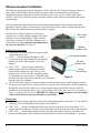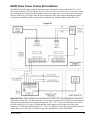
1
5000 Series Audio/Video System
Installation & Service Manual
08-315G (3/25/13)
Table of Contents
Description.....................................................................................................3
System Configuration.....................................................................................3
Cable Considerations......................................................................................4
Matrix Installation..........................................................................................4
Matrix / System Wiring Diagram...................................................................5
Lane Speaker/Driver Kit Installation.............................................................6
Cat 5 Lane Speaker/Driver Kit Installation....................................................7
Wireless Headset Installation.........................................................................8
5512 Remote Handset Installation.................................................................9
E10052 Wireless Expansion Adapter.............................................................9
5012 Remote Handset Installation...............................................................11
5570/5571 Remote Customer Audio Consoles............................................12
5572/5573 Remote Customer “In Wall” Audio Units..................................13
Remote Customer “In Wall” Audio/Video Unit (5574)...............................15
Auto-Greeter Board Installation & Use........................................................17
5550 (Current Style) Teller Video Unit Installation....................................19
5550 (Original Style) Teller Video Unit Installation...................................21
5650 Teller Video Unit Installation..............................................................23
5517 Remote Video Unit Installation...........................................................25
5617 Remote Video Unit Installation...........................................................27
E0885 Video Power Control Kit Installation...............................................29
5550/5517 LCD Menu Adjustments............................................................30
E0465-3WD-LP License Plate Camera Kit Installation...............................31
Audio Matrix Switch Settings......................................................................32
Video Matrix Switch Settings......................................................................33
Adjusting the Audio System........................................................................34
Mixing 5501 Series Consoles With Different Firmware Revisions.............35
Changing the Call Tone Type & Volume....................................................36
Colored Lane Stickers for 5501 Series Consoles.........................................36
System Operating Instructions.....................................................................37
Echo Canceller & Background Noise Cancellation.....................................38
5001-1 Stand Alone Audio System..............................................................39
Troubleshooting Tips...................................................................................40
Frequently Asked Questions........................................................................42
Greyfield Audio/Video Part Numbers..........................................................48
Part Number Photos.....................................................................................51
2
08-315G (3/25/13)
Description
The 5000 Series system consists of components that allow 2-way audio and video communications
between server (teller) consoles and customer units in banks, pharmacies and other service
environments. These systems allow both parties to hear and speak at the same time without feedback.
Inside and outside noises, other than speech, are screened out by using sharp cutoff filters to greatly
reduce sound outside the speech range. In addition, background noise cancellation circuitry in all 5000
Series audio consoles samples the incoming audio to the server (teller) using special algorithms to
virtually eliminate consistent, repetitive noise such as vehicle engines and mufflers.
System Configuration
To configure a new system using current components:
1) Start by determining the maximum number of consoles and customer lanes required and select
audio/video matrixes with an adequate number of ports. Note that some audio matrixes are shipped
with power supplies and others require that the power supply be ordered separately. All video
matrixes receive their power from the audio matrix.
Audio Matrix
5003..............1 on 2 (1 server on 2 customers) - includes power supply (see 5501-1 below)
5004..............2 on 2 - includes power supply
5002-4...........3 on 4 - requires power supply E10233
5002-8...........6 on 8 - requires power supply E10171
5002-12.........6 on 12 - requires power supply E10171
Video Matrix
5005-4...........3 on 4
5005-8...........6 on 8
5005-12.........6 on 12
Audio/Video Matrix
5006..............2 on 2 - includes power supply
2) Select the required number and size of audio consoles to meet the number of customer lanes.
5501-2...........2 lane
5501-4...........4 lane
5501-8...........8 lane
5501-12.........12 lane
5501-1...........This is a kit number that includes a 5501-2 audio console with a 5003 matrix.
3) Select the proper number of lane microphones and speakers if these do not already exist. Note that
there are a wide variety of electret microphones on the market and all have different characteristics.
Using an existing microphone may not provide optimum results. Also the system is designed for a 4
ohm speaker. A comparable 8 ohm speaker could be used but the volume would be reduced.
G3010...........Lane microphone with 6” leads
G3010L.........Lane microphone with 15 foot cable
G3011...........Lane speaker, 4 ohm, 3”
4) If video is being used, select the proper number of teller and customer video units if cameras and
monitors do not already exist.
5550..............Server (Teller) Video Unit - includes stand and power supply
5517..............Customer Remote Video Unit - includes mounting arm and power supply
E0885............Video Power Control Kit (When using 5517’s it is also recommended to order
a Video Power Control Kit so the customer monitors, and optionally the
cameras, can be turned off after hours. Only one required per system.)
08-315G (3/25/13)
3
Cable Considerations
Be sure to use the proper cable for connecting the matrix to the customer lanes. For audio it is HIGHLY
RECOMMENDED to use Greyfield cable (E0680) for distances up to approximately 180 feet. This
cable contains a 16AWG twisted pair for the speaker, a 20AWG twisted pair for the call button and a
20AWG twisted, shielded pair for the microphone. For distances over 180 feet it may be necessary to
use a heavier gauge of wire for the speaker to prevent excessive loss due to the wire resistance.
If you don’t use E0680 cable, make sure the microphone pair is individually shielded with it’s own
drain wire. DO NOT use cable with an overall shield. DO NOT use cable with individually shielded
pairs that have a common drain wire. If your cable has individually shielded pairs, with each pair having
it’s own drain wire, only connect the drain wire for the microphone pair. The drain wire must only be
connected at the matrix end as shown in figure 2.
Another option for audio is to use Category 5 cable (5E & 6 are also acceptable) for distances up to
1000 feet. Using this type of cable requires the Cat 5 Lane Speaker Driver Kit (E0958-KIT). 110VAC
must also be available at the lane. This kit can also be used to extend the length of standard E0680 audio
cable to a maximum of 1000 feet. See the section “Cat 5 Lane Speaker/Driver Kit Installation” for more
information.
For video applications use 75 ohm coax cable designed for CCTV applications. Belden 1426A is a very
good cable to use for reference. It has a solid copper center conductor and a copper braid providing 95%
shielding. Another option for video is to use twisted pair cable with video baluns. The specifications of
the video balun manufacturer must be followed as to the category of cable that is acceptable and whether
power is required.
Matrix Installation
Mount the audio (and video) matrix in an accessible but out of the way location near where the consoles
will be located. Figure 1 shows two mounting methods for all but the 5003 audio matrix which has a
small plastic enclosure with mounting tabs.
Figure 1
4
08-315G (3/25/13)
Matrix / System Wiring Diagram
Refer to Figure 2 for standard wiring connections. The drawing shows a 4-lane matrix but the same
wiring applies to all versions. Observe the following guidelines.
The ground wire connection shown for the audio matrix is not required for the 5003 matrix.
Be sure to only connect the drain wire for the microphone pair at the matrix end as shown.
For audio-only systems the audio console(s) may be plugged into any of the console ports of the
audio matrix. When video is used the console ports must match for a particular teller position.
For example if the audio console is plugged into CONSOLE 1 of the audio matrix, the camera
and monitor for that same teller must be plugged into CONSOLE 1 of the video matrix.
If auxiliary audio is used and the source only has a mono output, it may be plugged into either
the L or R connector on the audio matrix. The LEVEL pot adjusts the volume of the aux audio.
The auxiliary video source must provide composite video.
Figure 2
08-315G (3/25/13)
5
Lane Speaker/Driver Kit Installation
The Lane Speaker Driver Kit (E0892-KIT) is discontinued and is replaced by the E0958-KIT shown on
the next page. The E0958-KIT can be used with standard audio cable or Cat 5 cable. The E0892-KIT is
shown here for existing service purposes only. Audio cable from the matrix to the customer lane is
typically limited to approximately 180 feet with 16AWG speaker wire due to the resistance of the wire.
The Lane Speaker Driver Kit (E0892-KIT) allows the distance to be extended to a maximum of 1000
feet using standard E0680 audio cable.
Install the E0892 enclosure inside the customer unit in a convenient location.
Attach the cable from the matrix to the 7 pin connector (J2) per Figure 3.
Attach the lane speaker, microphone & call button to the 8 pin connector (J1).
Plug the 12VDC power supply into P1 (center pin positive) and into a 110VAC outlet in the unit.
The power LED (CR1) will light. * If 12VDC is already available in the unit, the E0892 board can
be powered at the 12VDC terminals of connector J1. DO NOT connect power to both P1 & J1. Use
one method or the other.
Adjust the speaker & microphone gain pots on the matrix for proper volume levels. (See the section
“Adjusting the Audio System” later in this document.)
Figure 3
6
08-315G (3/25/13)
Cat 5 Lane Speaker/Driver Kit Installation
The Cat 5 Lane Speaker Driver Kit (E0958-KIT) allows for the use of Cat 5 cable from the matrix to the
customer lane for distances up to 1000 feet. Cat 5e & Cat 6 may also be used. This kit can also be used
with standard E0680 audio cable to correct problems caused from excessive cable length.
Install the E0958 enclosure inside the customer unit in a convenient location.
Attach the cable from the matrix to the RJ-45 connector (J3) per Figure 4.
Attach the lane speaker, microphone & call button to the 8 pin connector (J2).
Plug the 12VDC power supply into J1 (center pin positive) and into a 110VAC outlet in the unit. * If
12VDC is already available in the unit, the E0958 board can be powered at the 12VDC terminals of
connector J2. DO NOT connect power to both J1 & J2. Use one method or the other.
Set R1 on the E0958 board to maximum volume (fully counter-clockwise) and set the speaker gain
pot on the matrix to 8:30. Only increase the speaker gain at the matrix if necessary and then in small
30 minute increments and retest. The E0958 board will boost the volume at the lane so keep the
speaker pot at the matrix as low as possible. The lane microphone adjustment is made at the matrix
as usual. (See the section “Adjusting the Audio System” later in this document.)
Figure 4
08-315G (3/25/13)
7
Wireless Headset Installation
The following instructions apply to Plantronics CS540, CS50 & CS55 Wireless Headsets. There are
many other wireless headsets on the market and many of these will most likely work fine but
compatibility cannot be guaranteed. Wireless headsets can be used on 5501, 5001 & 4001 Series
consoles. 3001 Series consoles typically experience volume issues with wireless headsets and are not
recommended.
Lane selections must still be made at the console when using headsets. Also call tones will sound
through the console speaker, not the headset, with all consoles having a built-in wireless headset jack.
This is a function of the board design and it cannot be changed.
All 5501 Series consoles and newer 5001 Series
consoles have a wireless headset adapter/jack built in
and do not use an external adapter. Older consoles
will require a model 5014 Wireless Adapter to use
wireless headsets. If a console has the adapter built
in, do not use the 5014. See Figure 5.
5501 Series
Console
Wireless
Headset Jack
Making the Connections
Connect the AC Power Adapter to the power jack
on the headset base unit.
5014 Wireless Adapter
CS540 – Connect the provided phone cable
between the back of the headset base unit and the
Wireless
headset jack of the audio console (or the 5014
Headset
Jack
adapter).
CS50 / CS55 – Connect the provided short
handset phone cable to the handset jack on the
Slot for
bottom of the headset base unit. There are two
Ground Wire
handset jacks; use the one with a complete picture
of a telephone, not just a picture of a handset. Plug
Figure 5
the other end of the cable into the headset jack of the audio
console (or the 5014 adapter).
The 5014 Wireless Adapter, if required, plugs into the back of the audio console using the speaker /
mic phono jacks. Remove the (4) screws and cover from the 5014 and feed the console ground wire
through the slot in the side of the case. Use the provided screw to attach the 5014 case with the
ground wire to the console chassis. (The wireless adapter label hides the screw hole in the photo in
Figure 5.) Replace the 5014 cover. IMPORTANT: The screw must be used to secure the adapter
to the console chassis to prevent intermittent connections.
Initial Setup
CS540 – On the bottom of the base unit set the Configuration Switch to the letter “A”. Set both the
Listening Volume and Speaking Volume dials to the number “3”.
CS50 / CS55 – Set the Configuration Dial on the left side of the base unit so the number “1” is
facing to the front of the base. Set the switch on the right side of the base unit to the single tic mark.
CS50 / CS55 – Set the Master Speak Volume located on the bottom of the base unit to the “B”
position and the Master Listen Volume located on the back of the base to the number “2” position.
8
08-315G (3/25/13)
Fine Tuning the Volumes
Make sure the speaker and microphone gain pots on the audio matrix have already been set for each
lane while in Console Mode. Never adjust these pots while using the headset. (See the section
“Adjusting the Audio System” later in this document.) You then switch to Wireless Mode and fine
tune the wireless volumes to match the console volumes.
CS540 – The rocker dial on the top end of the headset fine tunes the incoming volume. Be careful
not to press in on this dial accidentally as this dial is also the mute switch. Changes to the volume
dials on the bottom of the base can also be made if necessary.
CS50 / CS55 – The up (+) and down (-) buttons on the back of the wireless base fine tune the
outgoing volume. Each press of a button changes the volume one step. The rocker dial on the top
end of the headset fine tunes the incoming volume. Be careful not to press in on this dial accidentally
as this dial is also the mute switch.
Changing Between Console & Wireless Headset Use
With 5501 series consoles – Press the Wireless button (picture of antenna) while no lane is selected.
The yellow LED next to the button indicates wireless mode when lit.
With newer 5001 series consoles with built-in adapter – Press the Wireless/Camera button while no
lane is selected. The yellow LED under the microphone boom indicates wireless mode when lit.
With older consoles which require the 5014 Wireless Adapter – Use the toggle switch on the adapter
to switch between console and wireless mode.
E10052 Wireless Expansion Adapter
The E10052 Wireless Expansion Adapter is used to attach
multiple wireless headset base units to a single audio
console. The adapter includes a short cable to connect it to
the audio console. Additional jacks on the adapter are
used to connect up to three headset base units.
Connect up to 3 wireless
headset base units
When using the expansion adapter, if multiple headsets
are active at the same time the volumes will be slightly
reduced.
Connect directly to console or
5014 adapter as appropriate
Figure 6
5512 Remote Handset Installation
The Model 5512 Handset (see Figure 7) is a replacement for the older Model 5012W
(wall mount) and 5012H (side mount) handsets. It provides customer privacy and can
be used with 3000, 4000 and 5000 Series audio systems. The only operational
difference is removing the handset of the 5512 from its cradle does not initiate a
Teller Call like the 5012 did; a local call button must be used for this purpose.
However, the remote station speaker and microphone are disconnected while the
5512 handset is off hook, just like the 5012. This allows telephone-like loudness and
clarity as well as privacy. Important Note: The handset used with the 5512 is
different from the 5012 handset. If the actual handset is swapped to the other
model of unit, it will not work. Also note that local power was required for the older
5012 but is no longer needed with the 5512.
Figure 7
08-315G (3/25/13)
9
The Model 5512 can be wall mounted or mounted to the side of pneumatic tube drive-up units if desired.
Handsets that are used outdoors should be protected from direct rain.
Installation
1) Remove the 4 screws from the lid of the enclosure. This makes mounting the enclosure easy since
the entire contents are removed with the lid.
2) To wall mount the enclosure, drill mounting and cable holes in the rear of the enclosure. The upper
and lower dimples are positioned to match a single gang electrical box. Drill holes adequate for the
mounting screws that will be used. The center dimple needs to be drilled to allow for the matrix cable
and the local speaker/mic/call button cable. A minimum ¾” hole is recommended for these cables. To
side mount the box, mounting and cable holes will need to be drilled in the side of the enclosure as
required.
Figure 8
3) Connect the supplied paired cable to the remote station
Color
Destination
microphone, speaker and call button according to the chart in
Red
Microphone +
Figure 8. This cable plugs into J1 on the 5512 circuit board. If the
5512 will be used alone as a remote station without a local speaker
Black
Microphone and microphone, a call button will still need to be wired into this
Silver Mic. Shield - cut off
cable or there will be no way for the customer to call for service.
White Speaker
Black
Speaker
4) Connect the cable coming from the audio matrix to P1 on the
5512 circuit board. This connector can be unplugged while making
Green Call Button
connections and uses the same color code as is used at the matrix
Black
Call Button
lane connector. See Figure 9.
5) Reinstall the 5512 lid assembly,
taking care that no wires are
pinched. Hang up the handset.
6) Select the lane from an audio
console and adjust the audio matrix
SPK and MIC pots for that lane
while using the local speaker and
microphone at the remote station as
described in the audio matrix
instructions. Do not set the volume
any louder than necessary.
AUDIO MATRIX
-SP+
-TC+
Figure 9
5512
-MC+ SHLD
P1
BLACK
SP-
WHITE
SP+
BLACK
TC-
GREEN
TC+
BLACK
MC-
RED
MC+
SHIELD
7) Lift the handset from its cradle and check for adequate volume – the local speaker and microphone
should not work while the handset is off hook. If necessary, adjust the handset volume pots on the 5512
circuit board to balance the handset volume to the local speaker and microphone volumes. These pots
are labeled on the board.
10
08-315G (3/25/13)
5012 Remote Handset Installation
The 5012 Remote Handset has been replaced with the 5512 but is described here for service purposes.
With the 5012, removing the handset from its cradle initiates a Teller Call and disconnects the remote
station speaker and microphone. The 5012 is equipped with a hearing-aid compatible receiver.
Important Note: The handset used with the 5012 is different from the 5512 handset. If the actual
handset is swapped to the other model of unit, it will not work.
Model 5012H is mounted on the left side of pneumatic tube drive-up units, while Model 5012W is
designed for wall mounting, such as in lobby applications. These units can be used outdoors but should
be protected from rain.
Installation
Remove the cover from the 5012.
(Pneumatic unit mount only) – Determine a suitable location for the 5012H on the left side of the
pneumatic unit clear of its internal components and within easy reach of customers. Affix the
enclosed drilling template on the side of the pneumatic unit and drill the 5 holes. Secure the 5012H
to the pneumatic unit using appropriate hardware.
(Wall mount) – Secure the 5012W to the mounting surface using appropriate hardware.
Connect the paired pigtail cable exiting the 5012 to the remote station speaker, microphone and call
button according to the chart in Figure 8 on the previous page. The 5012 may be used alone without
a remote station speaker, microphone and call button by not using this pigtail cable. It can be
unplugged and removed but should be saved for possible future needs.
Pass the cable coming from the audio matrix through the cable port of the 5012 and connect it to the
5012 MATRIX terminal block. Unplug the connector to read the terminal labeling on the board. The
pinout is the same as at the
Figure 10
AUDIO MATRIX
matrix lane connector and is
5012 MATRIX
-SP+
-TC+
-MC+
SHLD
shown in Figure 10.
P1
Connect a source of 24VAC or
12VDC to the 3 pin connector
BLACK SPon the 5012 board. Unplug the
WHITE SP+
connector to read the pinout.
BLACK TCFor 24VAC use terminals 2 &
3. For 12VDC, terminal 1 is
GREEN TC+
positive and terminal 2 is
BLACK MCnegative. If a source is not
RED MC+
available, use part number
SHIELD
E0947 for a 12VDC / 1A power
supply.
If the 5012 is not mounted on a grounded electrical box or surface, connect the green wire to one of
its mounting screws. Otherwise, cut off and discard the green wire.
Reinstall the 5012 cover, taking care that no wires are pinched or interfere with the hook-switch
mechanism or contacts. Hang up the handset.
Adjust the speaker and microphone gain pots on the matrix while using the remote speaker and
microphone, not the handset. (See the section “Adjusting the Audio System” later in this document.)
Lift the handset from its cradle – a Teller Call tone is generated. Use the pots on the 5012 board if
necessary to balance the handset volumes with the remote speaker and microphone volumes.
08-315G (3/25/13)
11
5570/5571 Remote Customer Audio Consoles
Description
The 5570 & 5571 Remote Customer Audio Consoles consist of a speaker,
microphone and call button in a desktop type enclosure for indoor
applications (see Figure 11). The 5570 is intended for use with standard audio
cable and can be used for cable lengths up to approximately 180 feet. The
5571 is intended for use with Cat 5 cable and can be used for cable lengths up
to 1000 feet. A 12VDC power supply is included with the 5571 and requires a
110VAC outlet near the remote location.
Figure 11
In addition to free standing, the Remote Customer Audio Console can use the same
mounting options as the 5501 Teller Console. Use the 5501-HWB (Horizontal Wall
Bracket), the 5501-VWB (Vertical Wall Bracket) or the B6077 (Adjustable Desktop Stand) for mounting
flexibility.
Compatibility
The Remote Customer Audio Console should only be used in systems that have 5501 or newer 5001 (rev. 5
or 3.1) teller consoles. Also feature switch #7 on the audio matrix must be set to the UP position (dynamic
echo canceller learning). Avoid using 4001, 4101 or 3001 teller consoles which will result in excessive teller
echo. 3301 teller consoles may be acceptable if the volume levels are kept low.
Installation
Make connections between the audio matrix and the rear of the 5570/5571 using the appropriate cable. Use
standard E0680 audio cable for the 5570 (see Figure 12) and Cat 5 cable (or Cat 5e or Cat 6) for the 5571
(see Figure 13). Use the included power supply to provide 12VDC to the rear of the 5571. The power supply
must be close to the 5571. Do not significantly increase it’s cable length. For reference, the center pin of the
power supply barrel connector is positive. A raised tab is provided on the rear of the 5570/5571 to accept a
tie-wrap for cable strain relief if desired.
Figure 12
Figure 13
12
08-315G (3/25/13)
5572/5573 Remote Customer “In Wall” Audio Units
Description
The Remote Customer “In Wall” Audio Unit consists of a speaker,
microphone and call button in a recess mount double gang electrical box for
indoor applications (see Figure 14). The model 5572 is intended for use with
standard E0680 audio cable and can be used for cable lengths up to
approximately 180 feet. No remote power is required for the 5572. The model
5573 is used with Cat 5 cable and allows for cable runs up to 1000 feet. A
power supply is included with the 5573 and requires a 110VAC outlet near the
remote location.
Figure 14
Compatibility
The Remote Customer “In Wall” Audio Unit should only be used in systems that
have 5501 or newer 5001 (rev. 5 or 3.1) teller consoles. Also feature switch #7 on the audio matrix must
be set to the UP position (dynamic echo canceller learning). Keep the speaker and mic gain settings on
the matrix to the lowest level which will still allow adequate audio. Avoid using 4001, 4101 or 3001
teller consoles which will result in excessive teller echo.
Installation
Figure 15 shows a side view of the completed assembly before installation.
Remove the front plastic bezel from the unit by pressing the two plastic
tabs on the bottom with a screwdriver. Disconnect the wires from the call
button and set the bezel aside (see Figure 16).
Next remove the four philips head screws and remove the audio assembly
from the electrical box.
Determine the mounting location and cut an opening in the wall for the
double gang electrical box.
Figure 15
Fish the audio cable in the wall and through one of the cable slots in the rear of
the box. The power supply cable must also be installed if using the model
5573. The power supply must be in the vicinity of the 5573 so do not extend the
power supply cable any more than necessary.
Mount the electrical box in the wall by tightening the two screws which pull
the mounting tabs against the rear of the wall.
Attach the cable to the audio assembly. Figure 17 shows the rear of the 5572
and Figure 18 shows the rear of the 5573. Figure 19 shows the wiring of both
units to the audio matrix.
Note that the pot on the 5573 board must be set to the fully counter clockwise
position as shown in Figure 18.
Figure 16
Install the audio assembly in the electrical box using the philips head screws. Make sure the rear
plastic part of the bezel is in place (reference Figure 16). Attach the leads to the call button and then
snap the front bezel into place.
08-315G (3/25/13)
13
5572
Cable
Connector
Socket
5573
12VDC Power
Supply Socket
(center pin positive)
Leave pot set fully
counter clockwise
RJ45 Connector
for Cat 5 Cable
Figure 17
Figure 18
Figure 19
14
08-315G (3/25/13)
Remote Customer “In Wall” Audio/Video Unit (5574)
Description
The Remote Customer “In Wall” Audio/Video Unit consists of a speaker,
microphone and call button along with a camera in a recess mount triple
gang electrical box for indoor applications (see Figure 20). The model 5574
is intended for use with Cat 5 audio cable. Standard RG-59 coax cable can be
used for the camera. It is also possible to use twisted pair cable for the
camera by using video baluns (not included). See the documentation for your
video baluns for cable requirements if you decide to use that option. DO
Figure 20
NOT try to use the spare wire pair from the Cat 5 audio cable for the camera
as interference will result. A power supply is included with the 5574 and requires a 110VAC outlet near
the remote location.
Compatibility
The Remote Customer “In Wall” Audio/Video Unit should only be used in systems that have 5501 or
newer 5001 (rev. 5 or 3.1) teller consoles. Also feature switch #7 on the audio matrix must be set to the
UP position (dynamic echo canceller learning). Keep the speaker and mic gain settings on the matrix to
the lowest level which will still allow adequate audio. Avoid using 4001, 4101 or 3001 teller consoles
which will result in excessive teller echo.
Installation
Figure 21 shows a side view of the completed assembly before installation.
Remove the front plastic bezel from the unit by pressing the two plastic
tabs on the bottom with a screwdriver. Disconnect the wires from the call
button and set the bezel aside (see Figure 22).
Next remove four philips head screws and remove the audio assembly
from the electrical box. Also unplug the power cord from the audio
assembly to the camera. The camera should not need to be removed.
Determine the mounting location and cut an opening in the wall for the triple
gang electrical box.
Figure 21
Fish the audio, video and power cables in the wall and through the cable
slots in the rear of the box. (It is recommended to use the cable slots on
the left side where the camera is because of space constrictions.) The
power supply must be in the vicinity of the 5574 so do not extend the
power supply cable any more than necessary.
Mount the electrical box in the wall by tightening the two screws which
pull the mounting tabs against the rear of the wall.
Figure 22
Terminate an RJ-45 connector on the Cat 5 audio cable per the drawing in
Figure 23. Also install a BNC connector on the coax cable.
Attach the Cat 5 audio cable to the connector on the audio driver board, attach the coax cable to the
camera pigtail and plug the power supply cable into the audio driver board. See Figure 24.
Install the audio assembly in the electrical box using the philips head screws. Make sure the rear
plastic part of the bezel is in place.
08-315G (3/25/13)
15
Figure 23
12VDC Power for camera
(center pin positive)
12VDC Power
Supply socket
(center pin positive)
Leave pot set fully
counter clockwise
RJ45 Connector for
Cat 5 audio cable
Figure 24
Power up the 5574 and view the camera image on a monitor. Tilt the camera in it’s bracket for the
desired view.
Attach the leads to the call button and then snap the front bezel into place.
16
08-315G (3/25/13)
Auto-Greeter Board Installation & Use
Description
The Auto-Greeter Board is an optional accessory that can be installed inside a 5501 Series audio
console. Up to four messages may be recorded (or re-recorded) into the Auto-Greeter board. There are
two possible recording methods. Any of the four messages can be recorded by entering recording mode.
In addition, the first three messages can be recorded directly with the function keys without the need to
enter recording mode. (Function keys are not available on 12-lane consoles.) See the Auto-Greeter and
Message-Player operation sections below for functional descriptions. The message that is currently
enabled when exiting recording mode will become the auto-greeter message. Typically this should be
message #4 which leaves the first three messages available for message-player operation with the
function keys.
Installation
Compatibility Note: The newest version of the Auto-Greeter Board with an ISD1790 chip will only
work with consoles that have firmware revision 1.1 or higher installed. The firmware revision can be
found on the serial number label on the bottom of the console above the bar code. Note that the actual
EPROM for revision 1.1 will be labeled V1.05.00 which is the engineering number. The original version
of the Auto-Greeter Board with an ISD2560 chip will only work with consoles that have firmware
revision 1.0 installed. The actual EPROM for revision 1.0 will be labeled V1.03.03.
A revision 1.1 EPROM is included with new Auto-Greeter boards. Only install this EPROM if the 5501
console currently has a revision 1.0 EPROM. See additional information about revision 1.1 firmware in
the “5501 Series Audio Console Firmware” section of this manual.
Use ESD precautions when handling boards since both the auto-greeter board and the console main
board are static sensitive.
1. Unplug the matrix cable from the console so no power is applied.
2. Remove the (4) philips head screws from the bottom of the console.
3. Carefully separate the top of the console from the bottom using caution so no damage occurs to the
keypad ribbon cables. Unplug the two ribbon cable connectors along with the LED, microphone &
speaker connectors from the main board and set the top of the console aside. IMPORTANT – When
unplugging the ribbon cable connectors, DO NOT pull on the ribbon cables themselves as damage
will occur. Also make sure to avoid sharp bends or creases to the ribbon cables during handling.
4. Skip this step if the console already has revision 1.1 (or higher) firmware installed. Remove the
main board from the console – 3 screws hold it in place. Carefully replace the EPROM making sure
it is completely seated and no pins are bent and then re-install the board in the console. DO NOT
attempt to replace the EPROM while the board is installed since the board could be damaged from
flexing while pressing the EPROM into the socket.
5. Remove the jumper from pins 5 & 6 of the auto-greeter connector and save for future needs. The
auto-greeter connector is at the center of the main console board and is labeled.
6. Remove the auto-greeter board from the static bag and plug it onto its connector on the main console
board. Use the included spacer & screw to secure the board. Do not over tighten.
7. Plug the speaker, microphone, LED & keypad ribbon cable connectors back onto the main board
(it’s easiest to do the ribbon cables last) and re-install the top of the console to the bottom. The rear
panel of the console must slide into a slot on the top cover for a proper fit.
8. Make sure no cables are sticking out any side of the console and then re-install the (4) screws on the
bottom.
9. Plug the matrix cable back into the console and allow the audio system to initialize. Once the LED’s
are done blinking the auto-greeter messages can be recorded and tested.
08-315G (3/25/13)
17
Recording
Recording is done on a console by console basis. Messages recorded on one particular console can only
be played back through that same console.
Enter recording mode by pressing the HOLD key and the LANE 2 key at the same time while no
lane is selected.
Press the VOLUME UP key repeatedly to toggle through (4) possible auto-greeter message
numbers. The VOLUME DOWN key will also toggle through the message numbers in reverse order.
The currently enabled message is indicated by orange lights for lanes 1 & 2 as follows:
Message 1............Solid light for lane 1
Message 2............Solid light for lane 2
Message 3............Blinking light for lane 1
Message 4............Blinking light for lane 2
Disabled...............Solid lights for both lanes 1 & 2
To record (or re-record) the currently enabled message, hold the LANE 2 key and speak into the
microphone – release the key to stop recording.
To play back the currently enabled message through the console speaker for testing, press the LANE
1 key.
To exit programming mode, first make sure the desired auto-greeter message is enabled and then
press the HOLD key.
In addition to the above method, messages 1, 2 & 3 can be recorded (or re-recorded) without the need to
enter recording mode by using function keys F1, F2 & F3 respectively as follows. (Function keys are
available on all consoles except the 12-lane version.)
Make sure no lane is selected and then press and hold the appropriate function key. The light will
first begin blinking green. When the light changes to blinking red, speak into the microphone.
Release the function key to stop recording.
To play back message 1, 2 or 3 through the console speaker for testing, press the appropriate
function key while no lane is selected.
Auto-Greeter Operation
Make sure the desired message is enabled per the recording instructions above.
After a customer presses the call button, and while that lane light is blinking red, selecting that lane
from a teller console automatically plays the currently enabled message from that console to the
customer. The lane light will blink green while the message is playing and then turn solid green
when it is done.
Anything that causes the audio system to reset, such as a momentary power outage, will disable the
auto-greeter messages from all consoles. The messages will still be recorded but it will be necessary
to enter recording mode on each console to enable the desired auto-greeter message for that console.
Message-Player Operation
The Message-Player feature is not available on the 12-lane version of the console since that keypad does
not have function keys.
Select a lane and then press function key F1, F2 or F3 to play message 1, 2 or 3 respectively to the
customer. The lane light will blink green while the message is playing and then turn solid green
when it is done.
18
08-315G (3/25/13)
5550 (Current Style) Teller Video Unit Installation
The following instructions are for the current style 5550 which contains both a camera and 10.4” LCD
monitor for two way video. The 5550-1 is the same unit without a camera installed for one way video.
Installation
Figure 25
Remove the back cover from the stand by
pulling out from the top of the cover.
Access holes
Tilt the video head vertical and then remove it
to remove
from the stand by removing 4 screws. Insert a
video head
philips head screwdriver through holes in the
stand to access these screws (see Figure 25).
Using 75 ohm CCTV coax (Belden 1426A or
equivalent) with BNC connectors at each end,
Cable
connect the camera and monitor at the rear of
Clamps
the video head (see Figure 26) to the video
matrix. Make sure to match up the audio and
video port numbers at the matrixes. For example
if the audio console is connected to Console 2 of
the audio matrix, then the video cables from that
same teller position must be connected to Console 2 of the video matrix.
Connect the supplied 12VDC power supply to the power socket on the
back of the video head (see Figure 26). If a
Figure 26
different power supply must be used for some
reason, it must be rated for at least 2A. The
center conductor of the barrel connector is
positive. Do not power this unit using the power
Power &
Video
distribution board which was previously used
connections
with older B5450 units. The 5550 requires
on rear of
approximately 1.5A of current per unit.
video unit
With the power and video cables looped over
the top of the stand, re-connect the video head
to the stand. A choice of holes in the video head
brackets determines the overall height.
Snap the video and power cables into the cable
clamps on the back of the stand (see Figure 25).
Re-install the cover by first inserting the tabs on the bottom of the cover and then snap the top into
place.
Operation
Plug in the power supply and turn on the power switch on the bottom right side of the video head
(see Figure 27).
The height of the video head is fixed during installation. To change the height the video head must
be mounted to the stand using different mounting holes.
Tilt the video head by grasping the sides of the unit. The tilt tension is not adjustable. A swivel
mechanism is built into the base of the stand.
Use the lever next to the camera opening to tilt the camera up or down. Use the service/mirror switch
(see Figure 27) to see the camera image on the monitor. An alternate method is to press the HOLD
button on the audio console while no lane is selected. Then press HOLD again to return to normal
view.
08-315G (3/25/13)
19
Service Adjustments
A momentary service/mirror switch on the bottom left side of the
Figure 27
video head (see Figure 27) disconnects the external wiring
and internally connects the camera to the monitor for testing
purposes. The service/mirror switch does not exist on the
5550-1 since no camera is present.
he monitor has been adjusted at the factory but a menu
board allows settings to be changed if needed. The menu
board is attached to the plate on the rear of the LCD. See the
section “5550/5517 LCD Menu Adjustments” for more
information.
The camera has been adjusted at the factory but a camera
Service / Mirror
Power
Switch
menu board (only available on later units) attached to the
Switch
plate on the rear of the LCD screen allows camera settings to
be changed if needed. See Figure 28 for an explanation of the menu buttons. Use the service/mirror
switch or press the audio console hold button (with no lane selected) to connect the camera to the
monitor for viewing the menu. If focusing is required, loosen the small set screw on top of the lens
and then rotate the lens to the desired focus. Snug the set screw when finished but do not over
tighten to avoid creating a dimple in the lens threads making future fine adjustments difficult.
Camera Menu Board
UP
LEFT
RIGHT
DOWN
20
SET
Figure 28
SET:
Used to enter the OSD menu and select menu or submenu items.
UP:
Used to move up a line in a menu or submenu.
DOWN: Used to move down a line in a menu or submenu.
LEFT: Used to change setting values.
RIGHT: Used to change setting values.
Tip: Selecting “Reset from the “Special” menu returns all settings to their factory
values.
08-315G (3/25/13)
5550 (Original Style) Teller Video Unit Installation
The following instructions are for the original style 5550 that contains both a camera and 10.4” LCD
monitor for two-way video. The 5550-1 is the same unit without a camera installed for one-way video.
Assembly
The 5550 is shipped fully assembled except for the base. Remove the 4 screws from the bottom of
the stand and attach the base so the forks are pointed toward the front of the unit.
Optional 5550 Swivel Kit (B6075)
Note that the 5550 Swivel Kit is an optional accessory and is not included with the 5550 video unit.
Remove the (4) round-head screws from the bottom of the video unit base and separate the base
from the stand. These screws will not be reused.
Refer to the top photo in Figure 29 for attaching the swivel kit mounting plate to the video unit stand
using the (4) flat-head screws provided in the kit. Note that the ¼-20 threaded stud is offset from the
center of the plate. Be sure to orient the plate so the stud location matches the hole in the base.
Refer to the bottom photo in Figure 29 for attaching the base to the plate. Note that the pictures show
the stand and base upside down for clarity. The nylon washers are on each side of the base and the
metal washer is next to the ¼-20 locknut as shown.
Tighten the locknut to obtain the desired amount of swivel tension.
Figure 29
¼ - 20 Locknut
Base Will Install Between Nylon Washers
Swivel Kit Mounting Plate
Flathead Screws (4)
Video Unit Stand
Bottom View With Swivel Kit Installed
Video & Power Connections
Using 75 ohm CCTV coax (Belden 1426A or equivalent) with BNC connectors at each end, connect
the camera and monitor to the video matrix (see Figures 2 & 30). Make sure to match up the audio
and video port numbers at the matrixes. For example if the audio console is connected to Console 1
of the audio matrix, then the video cables from that same teller position must be connected to
Console 1 of the video matrix.
08-315G (3/25/13)
21
Connect the supplied 12VDC power supply to the
power socket on the back of the stand and plug it into
a 110VAC outlet. If a different power supply must be
used for some reason, it must be rated for at least 2A.
The center conductor of the barrel connector is
positive. Do not power this unit using the power
distribution board which was previously used with the
older B5450 unit. The 5550 requires approximately
1.5A of current per unit.
Figure 30
Operation
Turn on power to the video head using the toggle switch on the lower left of the stand.
Adjust the height of the video head as necessary by first loosening the adjustment knob on the back
of the stand. Tighten the knob when the desired height is achieved. Note that there are two holes in
the back of the stand for the adjustment knob. Using the top hole the height can be adjusted between
approximately 14.5”-19”. Using the bottom hole the height can be adjusted between approximately
14.5”-16”. The bottom hole also allows for a greater upward tilt angle at the lowest height allowing
the video unit to be placed under a hanging pneumatic terminal if desired.
Tilt the video head up by grasping the sides of the unit. The tilt latch bracket will lock the video head
into place in steps. Tilt the head back down by first slightly tilting further up to release pressure on
the tilt latch bracket and then pulling the handle of the bracket forward allowing the video head to
drop down. Note that there are two holes in the top of the tilt latch bracket. Mounting the bracket
using the opposite hole will allow the tilt angle to change slightly at each latch position.
Use the lever beside the camera opening to tilt the camera up or down.
Service Adjustments
Service adjustments require access to the inside of the video head. Remove the 6 screws from the
back side and remove the front cover.
Place the unit in “service” mode by placing the service switch at the upper left of the video head to
the rear position. This will connect the camera directly to the monitor. (The service switch does not
exist on the 5550-1.)
The camera has been focused at the factory and no further adjustment should be necessary. If
focusing is required, loosen the small set screw and then rotate the lens to the desired focus. Snug
the set screw when finished but do not over tighten to avoid creating a dimple in the lens threads
making future fine adjustments difficult.
The monitor is pre-adjusted at the factory but a menu board in each unit allows settings to be
changed. The menu board is located above the upper left of the LCD or below the LCD depending
on the version of the unit. See the section “5550/5517 LCD Menu Adjustments” for more
information. Important note for units that have the menu board above the upper left of the LCD – the
far left button changes the type of input that the LCD is expecting. Since it is very close to the service
switch it is possible to accidentally bump the button which would change the input. If a blue box
appears on the screen with the message “VGA No Signal” or “SV No Signal”, press the left button
to change the input back to AV.
Once all adjustments are satisfactory, place the unit in “normal” mode by placing the service switch
to the forward position. Replace the front cover.
An optional remote control unit (B6724), ordered separately, is available for use with the LCD
versions that have the menu board at the upper left. This allows adjustments to be made without
removing the front cover. The glass opening for the camera provides the path to the sensor which is
located on the menu board. Point the remote at an angle through the glass.
22
08-315G (3/25/13)
5650 Teller Video Unit Installation
The following instructions are for the 5650 which contains both a camera and 15” LCD monitor for twoway video. The 5650-1 is the same unit without a camera installed for one-way video.
Cable Connections
Remove the back cover from the stand by pulling out from the top of the cover.
If the audio console shelf will be used, attach it to the bracket of the stand by using the screws
already in the shelf. (Figure 31 shows the 5650 with the shelf attached.) The power and video cables
attached to the LCD, along with the audio console cable, should pass through the hole in the shelf
and back over the top of the stand.
Using 75 ohm CCTV coax (Belden 1426A or equivalent) with BNC connectors at each end, connect
the camera and monitor pigtails to the video matrix. Make sure to match up the audio and video port
numbers at the matrixes. For example if the audio console is connected to Console 2 of the audio
matrix, then the video cables from that same teller position must be connected to Console 2 of the
video matrix.
Connect the supplied 12VDC power supply to the power socket pigtail. If a different power supply
must be used for some reason, it must be rated for at least 3A. The center conductor of the barrel
connector is positive.
Snap the cables into the cable clamps on the back of the stand. Re-install the cover by first inserting
the tabs on the bottom of the cover and then snap the top into place.
Figure 31
Operation
Plug in the power supply and press the power switch on the bottom right side of the monitor.
To change the height simply lift up or press down on the monitor.
Tilt the assembly by grasping the sides of the monitor. A swivel mechanism is built into the base of
the stand.
The camera can be tilted independently from the monitor. The black screw on the top of the camera
hinge is used to adjust the tension of the tilt. To aid in adjusting the camera, press the HOLD button
on the audio console while no lane is selected to view your own image. Then press HOLD again to
return to normal view.
08-315G (3/25/13)
23
Service Adjustments
The Select button on the side of the monitor is used to select the appropriate input. It should be set
for AV. If the image on the screen displays “SV - No Signal” or “VGA - No Signal” press the select
button to set the input back to AV.
The monitor can be adjusted if needed using the menu buttons on the side of the monitor. See Figure
32 for an explanation of the menu buttons.
The camera has been adjusted at the factory but a menu board allows camera settings to be changed
if needed. The plastic camera housing must be opened to gain access to the menu board. See Figure
28 for an explanation of the menu buttons. Press the audio console hold button while no lane is
selected to connect the camera to the monitor for viewing the menu. If focusing is required, loosen
the small set screw on top of the lens and then rotate the lens to the desired focus. Snug the set screw
when finished but do not over tighten to avoid creating a dimple in the lens threads making future
fine adjustments difficult.
Figure 32
Monitor Menu Buttons
SELECT
MENU
–
+
Used to select the appropriate input. It should be set for AV. If the image on the screen
displays “SV - No Signal” or “VGA - No Signal” press the select button to set the input
back to AV.
Used to enter the OSD menu and select menu or submenu items.
Used to move down a line in a menu or submenu and decrease setting values.
Used to move up a line in a menu or submenu and decrease setting values.
Tip: Selecting “Reset” from the “Misc.” menu returns all settings to their factory values.
Note that the menu will not display if no input signal is present.
08-315G (3/25/13)
24
5517 Remote Video Unit Installation
The 5517 Remote Video Unit (10.4” LCD) requires 12VDC at approximately 2A to operate properly.
This requires that power be provided directly at the pneumatic unit to avoid the power drop associated
with long wire runs. Each 5517 is supplied with a power supply. An optional Video Power Control Kit
(E0885), ordered separately, is used to control the relay board in each video head so the monitors, and
optionally the cameras, can be turned off when desired. For larger installations it may be desirable to
have more than one power control kit if some lanes are closed at times while other lanes are open.
Optionally Hamilton Air pneumatic units that have an E0873 I/O Control Board can use an E10036
Video Power Control Cable to control the relay board in the video head. See the note below Figure 38.
The video head will be positioned to the top right of the pneumatic unit as viewed by the customer.
Use the template shipped with the 5517 to drill holes in the top of the pneumatic unit for the bracket
and cables. (The template ensures that the video head will not stick out past the front of the
pneumatic unit where it could be damaged by a vehicle.)
Refer to Figure 33. Feed the video cables, the power supply cable and the relay trigger wires from
the power control kit (or the E10036 Video Power Control Cable) from inside the pneumatic unit
through the top of the unit and through the video mounting arm. Apply a small amount of silicone
sealant to the bottom of the plate on the mounting arm (1) and attach the mounting bracket to the
pneumatic unit (2) with the supplied washers and nylon lock nuts.
Figure 33
Figure 34
Remove the screws from the back of the video head. Note that not all screws for the cover are
installed at the factory. The remaining screws are in the bag of accessories.
IMPORTANT NOTE: The LCD assembly is attached to the front of the video head enclosure
with the current version of 5517. Separate the front and back of the video head being careful not to
pull on the cables. Unplug the video and power cables from the LCD main board and set the front
aside.
Refer to Figure 34. Route the cables from the mounting arm (1) through the back of the video head
(3). Apply a small amount of silicone sealant to the plate of the mounting arm and attach the video
head to the mounting arm with screws (4) provided in the accessory bag. Two of the screws are
security type. A driver bit is included for the security screws.
Connect the monitor cable to the top left BNC connector and the camera cable to the top right BNC
connector in the video head as labeled. Connect the power supply cable and the relay trigger wires to
the relay board (see Figure 38). Slide the excess cable back through the bracket and into the
08-315G (3/25/13)
25
pneumatic unit and then install the end caps from the accessory bag into both ends of the mounting
arm.
Plug the power supply into a 110VAC outlet.
Tilt the camera vertically in its bracket to achieve the desired viewing angle. To view the image,
temporarily connect a service monitor to the “camera” BNC connector in place of your interconnect
cable. If a service monitor is not available it will be necessary to use the 5517 monitor. In this case
reconnect the video and power cables to the LCD. The yellow RCA connector is for video. Place the
unit in “service” mode by placing the service switch at the upper left of the video head to the rear
position. This will connect the camera video directly to the monitor. Note: If the video power control
kit in the teller area is not yet installed or turned on, it will be necessary to temporarily move the
video power wires from the switched to the un-switched terminals of the relay board to test the video
unit (see Figure 33).
The camera has been adjusted at the factory but a menu board (only available on later units)
attached to the rear mounting plate allows camera settings to be changed if needed. See Figure 23 for
an explanation of the menu buttons. Use the service switch in the 5517 if necessary to connect the
camera directly to the monitor for viewing the menu. If focusing is required, loosen the small set
screw and then rotate the lens to the desired focus. Snug the set screw when finished but do not over
tighten to avoid creating a dimple in the lens threads making future fine adjustments difficult.
The monitor has been pre-adjusted at the factory but a menu board allows settings to be changed.
The menu board is located on the rear of the LCD mounting plate for current versions. With older
versions the menu board was above the upper left of the LCD or below the LCD screen. See the
section “5550/5517 LCD Menu Adjustments” for more information. Important note for units that
have the menu board above the upper left of the LCD – the far left button changes the type of input
that the LCD is expecting. Since it is very close to the monitor BNC connector and the service switch
it is possible to accidentally bump the button which would change the input. If a blue box appears on
the screen with the message “VGA No Signal” or “SV No Signal”, press the left button to change
the input back to AV.
Once all adjustments are satisfactory, place the unit in “normal” mode by placing the service switch
to the forward position. Make sure the video and power cables are connected to the LCD (the
“yellow” RCA connector is for video) and replace the front cover, securing with all the screws. Two
of the screws are security type. A driver bit is included for the security screws.
26
08-315G (3/25/13)
5617 Remote Video Unit Installation
The 5617 Remote Video Unit (15” LCD) is ordered either as a post mount or side mount version. The
post mount version includes a 3” (square) x 36” post. The side mount unit includes an arm for attaching
to the top of a pneumatic unit. Each 5617 is supplied with a 12VDC power supply (minimum 3A). An
optional Video Power Control Kit (E0885), ordered separately, is used to control the relay board in each
video head so the monitors, and optionally the cameras, can be turned off when desired. For larger
installations it may be desirable to have more than one power control kit if some lanes are closed at
times while other lanes are open. Optionally Hamilton Air pneumatic units that have an E0873 I/O
Control Board can use an E10036 Video Power Control Cable to control the relay board in the video
head. See the note below Figure 38.
Post Mount Version Installation
The post mount 5617 should be mounted on the island to the
right side of the pneumatic unit (as viewed by the customer) at
a slight angle. See Figure 35 for the suggested location as
referenced from the front right corner of the
Figure 35
pneumatic unit. Existing site conditions may
require shifting the location
somewhat. Use the base of the stand
5.75
as a template for marking the hole
Base of Post
locations for
Right Front Corner
anchors. The holes
1.25
of Pneumatic Unit
in the base are sized
0.25
for 5/16” bolts.
Attach the 5617 to the post using the button head machine screws that are shipped
installed in the enclosure. Apply a small amount of silicone sealer between the post and the
enclosure.
Attach the furnished 12” piece of liquid tite tubing and fittings between the pneumatic unit and the
opening at the bottom of the post. Cables will route through this tubing.
Side Mount Version Installation
Use the template shipped with the 5617 to mark and drill holes in the top of the pneumatic unit.
Attach the 5617 to the arm using the button head machine screws that are shipped installed in the
enclosure. Apply a small amount of silicone sealer between the arm and the enclosure.
Attach the arm/enclosure assembly to the pneumatic unit using the included hardware. Apply a small
amount of silicone sealer between the arm and the pneumatic unit. Cables will route through the arm
into the unit.
Wiring
Figure 36 shows the inside of a 5617 unit with the back cover removed. The photo shows a version that
includes an audio speaker and microphone.
Connect the monitor video cable to the yellow RCA connector on the main board. A BNC to RCA
adapter is included for ease.
Connect the camera video cable to the yellow BNC flying lead.
Plug the power supply barrel connector into the side of the relay module.
Attach the relay trigger wires to the relay module. See Figure 38. The relay can be triggered either
from an E0885 Video Power Control Kit or directly from Hamilton Air units that have an I/O control
board using an E10036 Video Power Control Cable. Note that when using the E10036 cable with a
post mount 5617 the cable will not be long enough. In this case cut the 2 pin connector off the cable
08-315G (3/25/13)
27
Figure 36
and extend the cable length. Then attach the extended cable to
the trigger terminals per the drawing. The
trigger terminals and J3 on the relay
module are common.
If the 5617 includes audio, connect the
speaker wires to the black/white twisted
pair and the microphone wires to the
shielded cable. Note for Hamilton Air
units that have an I/O Control Board:
Connect the cable from the audio matrix
to the control board terminal strip as
usual. Cut the cables from the pneumatic
Speaker & Mic
unit speaker and microphone from their
Wires
connectors that plug onto the control
Camera Video
board. Attach a pigtail from those
connectors to the speaker and microphone
Relay Module for
in the 5617. Having the speaker and
Power Supply &
Trigger Wires
microphone in the 5617 attached to the
See Figure 36
control board in the pneumatic unit will
Monitor Video
allow the mute circuit to work properly.
Once the unit is powered up adjust the
camera vertically in its bracket to achieve
the desired viewing angle. If the unit is
not yet connected to the video matrix you
can use a BNC patch cable to temporarily connect the camera to the monitor. Note: If the video
power control kit in the teller area is not yet installed or turned on, it will be necessary to
temporarily move the video power wires from the switched to the unswitched terminals of the relay
board to test the video unit (see Figure 38).
The camera has been adjusted at the factory but a menu board allows settings to be changed if
needed. See Figure 28 for an explanation of the menu buttons. If focusing is required, loosen the
small set screw and then rotate the lens to the desired focus. Snug the set screw when finished but do
not over tighten to avoid creating a dimple in the lens threads making future fine adjustments
difficult.
The monitor has been adjusted at the factory but a menu board allows settings to be changed if
needed. See Figure 37 for an explanation of the menu buttons.
LCD Menu Board
1
2
3
Figure 37
4
1) Used to move up a line in a menu / submenu and to increase a setting value.
2) Used to enter the OSD menu, select menu / submenu items and accept changes to setting values.
3) Used to move down a line in a menu / submenu and to decrease a setting value.
4) Not used – this button may not be installed on the menu board.
Tip: Selecting “Reset” from the “Misc.” menu returns all settings to their factory values. Note that the
menu will not display if no input signal is present.
08-315G (3/25/13)
28
E0885 Video Power Control Kit Installation
The E0885 kit should only be used to control the power through the relay boards in the 5517 / 5617
video units as shown. DO NOT attempt to power video units directly with the power control kit. Follow
the wiring diagram in Figure 38. Wire gauge for the relay trigger wires is not critical since the current
draw for each relay coil is only 22ma. Be sure to follow the color code when connecting the lighted
switch to the control board. The switch can be mounted in any suitable location in the teller area.
Figure 38
Important Note: Newer Hamilton Air units that have an E0873 I/O Control Board do not require the
Video Power Control Kit. For these units use a Video Power Control Cable (E10036) to connect the I/O
Board in the pneumatic unit to the Relay Board in the 5517 / 5617. The 3 pin connector on one end of
the cable connects to J15 on the I/O Board and the 2 pin connector on the other end of the cable
connects to J3 of the Relay Board in the 5517 / 5617. The Night Lock switch for the pneumatic unit will
control the power to the relay coil which in turn will control power to the LCD Monitor.
08-315G (3/25/13)
29
5550/5517 LCD Menu Adjustments
Four types of LCD screens have been used to manufacture 5550 and 5517 video units. Refer to the
appropriate menu button arrangement below for tips on navigating the menu.
This menu board is located below the LCD screen. A dual
color LED on the right side of the board indicates power
status: green = on & red = standby.
1) Turns the monitor power on or off.
2) Not used.
3) Used to enter the OSD menu, select menu items and accept changes to setting values.
4) Used to move down a line in a submenu or to decrease a setting value.
5) Used to move up a line in a submenu or to increase a setting value.
Tip: Selecting “Factory Default” from the main menu returns all settings to their factory values.
This menu board is located at the top left of the video unit at an angle.
1 2 3 4 5
1) When not in the OSD menu: Toggles between the possible monitor inputs (AV-SV-VGA). It must
be set to AV.
When in the OSD menu: Used to move up a line in a submenu or to increase a setting value.
2) Used to enter the OSD menu, select menu items and accept changes to setting values.
3) Used to move down a line in a submenu or to decrease a setting value.
4) Not used.
5) Not used.
Tip: Selecting “Reset” from the Misc. menu returns all settings to their factory values.
A remote control (B6724) can be used to adjust this LCD without removing the cover from the unit.
This menu board is located below the LCD screen. A green power
LED is on the left side of the board.
1) Used to move up in menus and sub menus.
2) Used to move down in menus and sub menus.
3) Used to enter or exit the OSD menu and accept changes to setting values.
4) Used to enter into menus and sub menus and increase setting values.
5) Used to enter into menus and sub menus and decrease setting values.
Tip: Selecting “Reset” from the function menu returns all settings to their factory values.
This menu board is located on the plate on the back of the
LCD screen.
1) Used to move up a line in a menu / submenu and to increase a setting value.
2) Used to enter the OSD menu, select menu / submenu items and accept changes to setting values.
3) Used to move down a line in a menu / submenu and to decrease a setting value.
4) Not used – this button may not be installed on the menu board.
Tip: Selecting “Reset” from the Misc menu returns all settings to their factory values. Note that the
menu will not display if no input signal is present.
30
08-315G (3/25/13)
E0465-3WD-LP License Plate Camera Kit Installation
The following instructions are for mounting the License Plate Camera assembly on the back side of a
5517 Video Unit. This camera is used for viewing the rear license plate of a vehicle as it leaves the
drive-up lane. It can be oriented to view the vehicle in the same lane as the 5517 it is attached to or the
vehicle in the previous lane simply by shifting the camera housing 90° on it’s bracket. See the photos in
Figure 39.
1)
Remove the cover from the License Plate Camera assembly by
Figure 39
removing the 2 screws from the rear of the housing. Pull the
video/power cable up through the housing so it is no longer
Backside of 5517 Video Unit
passing through the square tube on the bottom.
2) Remove the plastic end cap from the outer end of the 5517
mounting bracket.
3) Insert the square tube of the License Plate Camera assembly
into the end of the 5517 bracket. While holding the
assembly in place, drill a hole through the bottom of the
5517 bracket up through the inner bracket using a #29 or
1/8” drill bit. This hole will be used later to hold the
assembly in place but for now remove the assembly.
4) A power converter is provided with the kit which converts
24VAC from the pneumatic unit to 12VDC for the new
camera. Feed the barrel connector end of the power
converter along with a video cable from inside the
Drill Hole Here
pneumatic unit up through and out the end of the 5517
Oriented for Viewing
mounting bracket.
the Previous Lane
5) Temporarily feed the power cable through the License Plate
Camera bracket so it can be connected to the camera power
cable. Slide the assembly back into the 5517 bracket. It will
be necessary to slightly push the new video cable back into
the bracket.
6) Connect the power converter input wires to the 24VAC
terminals of the pneumatic unit. IMPORTANT: If the
“24VAC” source is actually 28V or higher a resistor must
be placed in series with one side of the input to the power
converter to lower the voltage and prevent damage. A 47
ohm ½ watt resistor will generally work.
7) Connect a service monitor to the video pigtail which is still
hanging out the top side of the License Plate Camera
assembly. Adjust the camera bracket as necessary to get the
proper view.
8) Disconnect the service monitor and power cables from the
License Plate Camera pigtail and remove the assembly.
9) Feed the video/power pigtail cable back through the License
Plate Camera bracket like it was initially and re-install the
Oriented for Viewing
cover.
the Same Lane as 5517
10) Attach the pigtail to the video and power cables and insert the
Where Installed
License Plate Camera bracket back into the 5517 bracket.
Secure it in place with the #8 x 3/8” stainless steel screw
included with the kit.
11) Connect the remote end of the new video cable and check the new camera for proper operation.
08-315G (3/25/13)
31
Audio Matrix Switch Settings
Refer to Figure 40 for the dip switch pack located on the end of the audio matrix. Factory settings are
shown in bold. Cycle power to the matrix after making any changes to these switches.
Figure 40
Feature
Lane Order 1
1
2
3
4
5
6
7
Switch #
1
Up (Off)
Normal
Down (On)
Reverse
Console Limit 2
2
2 Per Lane
1 Per Lane
Delayed Unmute 3
3
No Delay
1 Second
Delayed Unmute 3
4
No Delay
2 Seconds
Aux. Audio Mode 4
5
Normal
Noise Abate
Call Tone Default 5
6
Normal
Erase
Echo Canceller 6
7
Dynamic Learning
Fixed Learning
Background Noise Cancellation 6
8
Off at Startup 7
On at Startup
Determines whether the console lane buttons work from left to right (normal) or right to left
(reverse). This switch must be UP for 5501 Series consoles.
Determines if more than one console can select the same lane at the same time. Volume levels will
be reduced when multiple consoles select the same lane. This switch has no effect with a 5003
matrix.
The mute circuit is wired so the closure of an auxiliary contact of the blower relay shorts across the
lane microphone to mute the incoming audio while the blower is running. These switches
determine the length of delay after the microphone short is removed until the incoming audio
comes back on to allow for motor wind down time. The switches can be combined to give a 3
second delay.
Noise Abate mutes the auxiliary audio (if used) until the call button is pressed or the lane is put on
hold. This feature is generally used if the facility is near a housing development to prevent
complaints from the residents. This switch has no effect with a 5003 matrix.
This determines whether the call tone programming goes back to factory default (erase) when the
system goes through a reset or whether the programming is saved (normal) and only applies to
older matrixes. The programming is always saved with a 5000 Series matrix regardless of the
position of this switch.
These switches as listed are for features in all 5501 Series consoles and 5001 Series consoles that
are revision 3.1 or higher. See an explanation of these features in the section “Echo Canceller &
Background Noise Cancellation” later in this document. The echo canceller must be set for
dynamic learning when using 5501 consoles.
5501 Series consoles with revision 2.4 or higher firmware do not allow background noise
cancellation to be turned completely off. The “off” position with these consoles is actually “on
partial”.
MIC DC Switches: These switches only exist on older 5000 Series audio matrixes and are used to
determine if the lane microphone is a Dynamic (UP) or Electret Condenser (DOWN) type. Since the
electret type is standard (and recommended) this switch must be down or the mic will not work. All
newer matrixes are hard-wired to this position and do not include the switches to avoid service issues.
32
08-315G (3/25/13)
Video Matrix Switch Settings
Refer to Figure 41 for the dip switch pack located on the end of the video matrix. Factory settings are
shown in bold.
Figure 41
Feature
Idle Console View 1
Aux. Video 2
Not Used
Lane Shift 3
Not Used
1
2
3
Switch #
1
Up (Off)
Driveway Only
Down (On)
All Cameras
2
Normal
Static
3
4
X
Normal
Shifted
5
X
Determines what the teller sees while no lane is selected. If a driveway camera is not connected,
the teller will see a rotation of all lane cameras regardless of this switch position.
If the auxiliary video input works properly leave this switch in the factory setting; otherwise try the
opposite setting.
This switch causes the lane numbers on the video matrix to be associated with the next higher lane
number on the audio matrix. For example, assume a facility has 5 lanes of audio with lane 1 being
a deal drawer and lanes 2 through 5 being pneumatic units. If video was only being used on the
pneumatic units you could get by with a 4-lane video matrix by shifting the lanes on the video
matrix so they would be associated with audio lanes 2 through 5.
Termination Switches: These switches, labeled TERM on the matrix, are used to terminate the end of
the cable run at 75 ohms. There is a switch for each lane camera and the driveway camera. If the cable
from the camera “terminates” at the matrix, the switch must be ON. If the cable is t-tapped at the matrix
to run to another device, such as a DVR, the switch must be OFF since the termination must happen at
the end of the cable run. Improper termination will degrade the picture quality and can cause other
problems such as the system not staying locked on to a lane camera after the teller selects that lane.
A word about t-tapping: Even though t-tapping causes a loss of signal level, this method works fine
most of the time. Occasionally this method will not work and it will be necessary to install a video
distribution amp for each camera involved. Also if the t-tap does not happen directly at the matrix it will
be necessary to use video distribution amps since there is no single end-of-line. A small video
distribution amp with 1 input and 2 outputs can be ordered using part number E10039.
An alternate wiring method may be to run the lane camera cables directly to the DVR if that device has
true looping outputs (meaning the signal is re-generated). In that case the DVR would generate a fresh,
full signal which could be “terminated” at the video matrix.
08-315G (3/25/13)
33
Adjusting the Audio System
The speaker (SPK) and microphone (MIC) pots on the audio matrix (see Figure 2) provide the main
volume adjustment for the system. There are a set of pots for each customer lane. The speaker pot
adjusts the outgoing volume to the customer lane while the microphone pot adjusts the incoming volume
to the teller. The best adjustments are made with one person at the audio console and another person in a
vehicle at the customer lane.
Adjust the SPK and MIC pots based on the orientation of a clock with 12:00 being mid range. Audio
matrixes leave the factory with these pots set at approximately 10:00.
If wireless headsets will be used, make all matrix adjustments while in Console Mode using the
console speaker and microphone, not the headset. After the matrix is adjusted satisfactorily then
switch to Headset Mode and adjust the headset using it’s own adjustments to balance the volume
levels obtained with the console. Headset adjustment procedures are found in the section “Wireless
Headset Installation”.
When using 5512 Remote Handsets, make all matrix adjustments while using the remote speaker
and microphone at the lane, not the handset. Then lift the handset off the cradle and use the pots on
the handset board to balance the volume levels. See the section “5512 Remote Handset Installation”.
When using standard audio cable: Select a lane from an audio console and speak directly into the
console microphone at the recommended distance *. Adjust the speaker pot on the matrix for
adequate but not excessive volume at the lane. The default setting is ideal for many installations and
can be reduced on some. Getting too close to the mic or setting the pot too high can have a negative
affect and add static sounding artifacts to the audio.
When using Cat 5 cable or standard audio cable with the E0958-KIT: Set pot R1 on the E0958 lane
module to it’s maximum setting (fully counter-clockwise). Set the speaker pot on the matrix to 8:30.
Select a lane from an audio console and speak directly into the console microphone at the
recommended distance *. There should be adequate volume at the lane at this setting since the
amplification takes place at the lane module. Only increase the speaker gain at the matrix if
necessary and then in small 30 minute increments and retest. See the section “Cat 5 Lane
Speaker/Driver Kit Installation”.
With the lane still selected adjust the mic pot on the matrix for adequate but not excessive incoming
volume while the person at the customer lane speaks toward the microphone. Make small
adjustments at a time – approximately 30 minutes. Do not set the mic pot higher than necessary. Do
not adjust the volume using the console volume arrows at this time. The console volume can later be
adjusted by each teller for their individual preference. Note that any changes made using the console
volume arrows will revert back to a default level whenever the system is reset.
Do not automatically assume that all lanes should be adjusted to the same settings. Acoustics and
other factors can vary from lane to lane, especially with deal drawers.
The system operates in full duplex mode, meaning audio is active both directions at the same time.
However, to give the teller priority in the conversation the incoming volume is reduced while the
teller speaks into the microphone.
*
34
The recommended distance for speaking into the console microphone is 1” to 2” on all consoles
except for 5501 series consoles that have revision 1.1 or 2.2 firmware. For those consoles the
recommended distance is 3” to 6” unless the mic gain pot on the console has been adjusted as shown
in the section “Mixing 5501 Series Consoles With Different Firmware Revisions”.
08-315G (3/25/13)
Mixing 5501 Series Consoles With Different Firmware Revisions
Audio adjustment issues often occur when 5501 series consoles with different firmware revisions are
mixed on the same system due to the difference in outgoing volume. The firmware revision is identified
on the serial number label above the bar code. The label is on the bottom of the console. The following
provides a guide for adjusting the mic gain on each console so the volume levels are very close.
Puncture the black dot on the label on the bottom of the console so you can see the arrow on the
adjustment pot through the bottom of the circuit board. Adjust the pot so the arrow points as indicated
below for the appropriate firmware revision in the console.
Firmware 1.0 – The arrow should point toward the word “key” on the line directly below the hole.
Firmware 1.1 & 2.2 – The arrow should point toward the word “Notes” on the lower left of the label.
Firmware 2.3, 2.4, 2.5 & 2.6 – The arrow should point toward the word “Press” directly below the hole.
Firmware 2.7 – The arrow should point away from the arrow on the label next to the pot opening.
Adjust the speaker and mic gain pots for each lane on the matrix to approximately 10:00. 12:00 is mid
range. Additionally make sure that feature switch #7 on the matrix is UP for dynamic echo canceller
learning and switch #8 is DOWN for defaulting background noise cancellation to on. Instruct the tellers
that leaving background noise cancellation on allows these consoles to work much better. Cycle power
to the matrix and then test the system. The volume from each console should be very close when
speaking 1” to 2” from the console microphone. Only make small adjustments at the matrix if necessary.
These settings should provide good volume unless other problems exist. Contact tech support at 877236-0245 with any questions.
2.7
O O
1.0
O
1.1
2.2
2.3 - 2.4 - 2.5 - 2.6
08-315G (3/25/13)
35
Changing the Call Tone Type & Volume
The call tone type and volume are system wide parameters which are stored in the audio matrix. Any
audio console in the system can be used to change these parameters as follows.
Press the LANE 1 key and the HOLD key at the same time. Lane 1 & 2 indicators light orange.
Press the LANE 2 key to rotate through the call tone types until the desired tone is heard.
Press the LANE 1 key to rotate through the volume levels until the desired level is heard.
call tones will sound every few seconds until a teller selects the lane.
Press the HOLD key to exit programming mode.
Colored Lane Stickers for 5501 Series Consoles
5501 Series audio consoles use colored stickers as lane indicators. The colors are visible through clear
windows by each lane key.
Slide the plastic stick out the side of the console and attach the colored lane stickers as required
following the guide marks on the stick. See Figure 42.
Lane numbering is from left to right across the top row of lane keys followed by left to right across
the bottom row of lane keys. F1, F2, F3 & Noise Cancel keys do not require colored stickers.
Figure 42
36
08-315G (3/25/13)
System Operating Instructions
Each lane key on the audio console has an indicator light. Interpret the lights as follows.
RED (fast flash)...........................Customer CALLING for service
GREEN (steady)..........................Customer in 2-WAY CONTACT with your console
RED (steady)................................Customer in 2-WAY CONTACT with another console
GREEN (slow flash)....................Customer placed on HOLD from your console
RED (slow flash).........................Customer placed on HOLD from another console
Operate the Teller Console as follows.
To CONTACT a customer calling.................................Press the LANE key
To place a customer on HOLD......................................Press the HOLD key (indicator blinks)
To CONTACT a customer on HOLD............................Press the LANE key
To END contact with customer......................................Press the active LANE key
To CANCEL hold and END contact..............................Press the LANE key twice
To TALK OVER a customer.........................................Hold down the active LANE key
To toggle between console & wireless headset..............Press WIRELESS key (no lane selected)
Yellow light on = wireless mode
To view yourself............................................................Press HOLD key (no lane selected)
To toggle background noise cancellation
5501 consoles (except 12-lane version)......................Press NOISE CANCEL button
On or Off (indicated by Noise Cancel light)
Green = On Red = Off *
On or Off (indicated by Lanes 1&3 or 1&2 lights) Green = On Red = Off *
5501 Series consoles with revision 2.4 or higher firmware do not allow background noise
cancellation to be turned completely off. The “off” position with these consoles is actually “on
partial”.
You can contact any customer who is on HOLD from any teller console.
The system may be configured for multiple consoles to contact a lane at the same time. See Feature
Switch #2 in the section “Audio Matrix Switch Settings”.
To prevent loss of sound quality avoid leaving a lane selected when no customer is present.
A wireless headset will not work unless it is communicating with its base unit. With Plantronics
units press the long, silver button on the face of the headset. Green lights on the headset and the base
unit indicate they are communicating. Lanes must be selected at the audio console – they cannot be
selected from the headset.
See the section “Auto-Greeter Board Installation & Use” for instructions on this board (if installed).
An Operating Instructions sticker can be found on the bottom of all 5501 Series consoles.
Additional Information for Video
In the idle view (no lane selected) the teller will see either the driveway camera only or a rotation of
all lane cameras including the driveway camera. See Feature Switch # 1 in the section “Video Matrix
Switch Settings”.
When a customer lane is not selected, the customer will see the Auxiliary Video (if present). If there
is no Auxiliary Video, the customer will see their own image from that lane camera.
08-315G (3/25/13)
37
Echo Canceller & Background Noise Cancellation
Feature Switches 7 & 8 on the audio matrix are used to set parameters for the audio processor in each
audio console to control how the echo canceller and background noise cancellation work. These features
are set each time the system goes through a reset. See the section “Audio Matrix Switch Settings”.
Echo Canceller
When the teller speaks into the console mic the sound goes out the customer speaker, bounces off the
customer vehicle, is picked up by the customer mic and then comes out the teller speaker. In effect, the
teller hears their own voice. The echo cancellation circuitry in 5000 Series consoles is designed to
eliminate this issue. The echo canceller can have either dynamic or fixed learning. Dynamic learning
adjusts for the best possible cancellation setting while a lane is selected. Note that the console has to
sample the echo before it can attempt to remove it. For this reason the teller may hear their own voice
for the first couple of words or so while “learning” takes place. The learning time is increased as the
amount of echo changes such as when speaking to a customer in a small vehicle (not much echo)
followed by a customer in a panel van (lot’s of echo). Deal drawers are also the most problematic for
echo because sound bounces back and forth between the vehicle and the building/window. Another
point to consider is that the audio processor will have a much more difficult time canceling echo if it is
overdriven. This happens when volume settings are too high or when speaking too close to the
microphone with a loud voice. This will also cause undesirable artifacts in the audio such as static or
cutting out of the customer’s voice. Fixed echo canceller learning is not recommended with 5501 Series
consoles.
IMPORTANT: For the audio processor / echo canceller to work properly it is necessary that the lane
microphone wire pair be properly shielded from the matrix to the lane. See the sections “Cable
Considerations” and “Matrix / System Wiring Diagram” for more information.
Background Noise Cancellation
Background noise comes from a variety of sources. The background noise filtering in 5000 Series
consoles works best at reducing constant and consistent sounds such as engine and muffler noise from a
vehicle at the lane. Varying noise such as traffic from a nearby street can sometimes cause a side effect
in the audio processor that most people describe as an underwater or gurgling sound. The symptom gets
worse as the gains on the matrix pots are increased, the volume adjustment on the console is increased,
or the level of the background noise increases.
Regardless of the default noise cancellation setting from the matrix, background noise cancellation can
be toggled on or off * on a console by console basis with all 5501 Series consoles and most 5001 Series
consoles (rev. 3.1 & higher). On all but the 12-lane version of the 5501, pressing the Noise Cancel
button toggles this feature on (green LED) or off * (red LED). With the 12-lane version of the 5501 and
by the LED’s for lanes 1 & 3 or 1 & 2 (green = on & red = off *). Changes of this feature made from a
console only apply to that particular console and will always revert back to the current setting of dip
switch 8 from the matrix whenever the system goes through a reset, such as following a momentary
power outage. For this reason the technician should select the dip switch setting that corresponds to the
most common setting used by the tellers.
* 5501 Series consoles with firmware revision 2.4 or higher do not allow background noise cancellation
to be turned completely off. For these consoles a green LED indicates “on full” and a red LED indicates
“on partial”. All 5501 consoles work best with background noise cancellation turned on.
38
08-315G (3/25/13)
5001-1 Stand Alone Audio System
The model 5001-1 Audio System is a discontinued product that is shown here for service purposes. The
replacement is a 5501-1 which is a kit consisting of a 5501-2 Console, a 5003 Matrix and a power
supply. Both systems provide full-duplex communication for a single console with one or two customer
stations in remote drive-up or walk-up situations where integrated video is not required.
Lane Terminals
Mount the terminal board to a convenient surface that is well
protected from mechanical damage and near the desired console
location. Connect the remote stations to the 7-position terminal
blocks as shown in Figure 43. Plug the console into the RJ-type
jack and the DC power pack into the DC power jack. Connect the
GND terminal to a building ground. Do not ground the remote unit
end of the microphone shields.
Figure 43
Test the system using the factory default settings without making
any changes. The factory default positions and how to read the pot
positions are shown in Figure 44.
Teller Call Volume
Adjust Call Tone Volume for sufficient volume of the teller call
tone when the call button on a remote station is pressed.
Lane 1 Speaker Volume
With an assistant in a vehicle parked at the lane, speak in a normal
tone of voice about 2 inches from the console microphone and
check that the audio level is OK at the lane. Adjust the lane SPK
pot for sufficient volume in the vehicle if necessary. Make small
adjustments at a time and retest. Do not adjust the lane SPK pot
above 9:00 – it won’t usually make the volume louder at the lane
beyond this point.
Lane 2 Mic Volume
Set the MIC pot 1 hour above the lane SPK pot. Have an assistant in the vehicle speak in a normal tone
of voice toward the remote unit and check that the audio level is OK at the console. Adjust the volume
on the console as needed. Only adjust the lane MIC pot if necessary and then only by small amounts.
Figure 44
08-315G (3/25/13)
39
Repeat for the 2nd Lane
Set the lane 2 pots to the same settings as lane 1 and test. Usually these settings will work for both lanes.
If adjustments need to be made, follow the steps above.
Adjustment Hint: The 5001-1 Audio System does not like to be too loud. Adjust the volumes to the
lowest settings where the level is OK. Cranking the volumes up usually makes things worse.
Operating Modes
The Operating Mode is controlled by an internal bank of 2 switches which set features of the audio
processor. Remove the 4 console cabinet screws for access to the dipswitch bank. The dipswitch closest
to the edge of the board is dipswitch 1. Always remove power to the console when changing the switch
positions. The function of these switches is as follows. See the section “Echo Canceller & Background
Noise Cancellation” for more information.
Switch 1 UP..................DYNAMIC Echo Canceller Learning
Switch 1 DOWN...........FIXED Echo Canceller Learning
Switch 2 DOWN...........Background Noise Cancellation ON
Switch 2 UP..................Background Noise Cancellation OFF
Operating Instructions
Each Lane Key has an indicator light. Interpret the Indicator Lights as follows:
RED...............Customer CALLING for service
GREEN..........Customer in 2-WAY CONTACT with you
Operate the Teller Console as follows:
To CONTACT a customer calling....................................Press the LANE key
To END contact with a customer......................................Press the active LANE key
To TALK OVER a customer............................................Hold down the active LANE key
Indicated by Lane 1 LED
(Green = ON Red = OFF)
Troubleshooting Tips
System won’t initialize (console lights continue to blink red or stay lit) – The audio consoles,
audio matrix and video matrix all communicate by RS-485 through the Cat 5 cables. A problem with
any of these devices can cause a system wide problem like this. Power down and disconnect all but
one audio console – also disconnect the video matrix if present. Power up and see if the system will
initialize with a single console. If it does, start adding devices back one at a time until it fails again to
determine the cause. If the first console failed to initialize, try a different one. Don’t rule out the
possibility that a storm or power surge could have damaged multiple devices. Also be aware that
some matrix failures are only related to a particular console port.
Power supply issues – 1A “wall wart” power supplies have an internal fuse. If the output gets
shorted the power supply will be destroyed. Old Samlex power supplies (large, heavy enclosure)
should be watched closely and replaced if possible. As they begin to break down with age their
output will not have clean DC current and the voltage will slowly rise, sometimes to levels that can
damage equipment.
40
08-315G (3/25/13)
Audio issues – Isolate audio problems by determining if the problem exists only when using a
particular audio console or when communicating with a particular lane. Before deciding that a
particular console is bad, try plugging it into a different port of the matrix. Lane connectors can also
be swapped at the matrix to see if a problem follows the physical lane or stays with the same lane
number on the matrix. Be aware that the main amplification for outgoing audio is in the matrix but
the main amplification for incoming audio is in the console.
Intermittent problems with the quality of audio are often caused by overdriving the audio processor
(volume levels too loud) or speaking too close to the console mic with a loud voice. Also make sure
that the proper type of cable is being used. Many times when equipment is upgraded the cabling
from the matrix to the lane is reused. That cable may not be acceptable for the new system. See the
section “Cable Considerations”.
Video issues – Some video issues can be isolated by swapping cameras or monitors at the video
matrix. You can disconnect a lane camera and a teller monitor from the matrix and connect them
together with a barrel connector. Other combinations of cameras and monitors can be connected
together like this to rule out a possible video matrix problem. Barrel connectors and patch cables
are tools that should be carried by technicians installing or servicing this type of equipment.
The auxiliary video input of the matrix can be tested by temporarily moving a lane camera or teller
camera to the auxiliary input. Remember that the auxiliary input must be composite video. If a
particular source for the auxiliary video won’t work through the matrix, but it will work when
connected directly to a monitor, try changing feature switch #2 on the video matrix to the opposite
position.
Also don’t forget to check for the proper setting of the termination switches on the matrix. Improper
termination is responsible for many video problems such as inconsistently locking onto a lane
camera when that lane is selected by a teller. The section “Video Matrix Switch Settings” gives
details about the termination switches and t-tapping video cables.
Wireless Headset issues –Make sure the battery has a full charge before using the headset. The
charging light on the base unit will blink while the battery is charging and will light steady when
charging is complete. The Plantronics headsets are mated units so mixing up a headset with the
wrong base unit will give the impression of a defective unit. Also the CS50 / CS55 headset can
occasionally get into a state where it will not work – it may just produce loud static. To clear this
condition put the headset through a reset as follows:
1. Press both the talk button and the mute control button on the headset for 5 seconds. The mute
control is the volume dial pressed in.
2. When the talk indicator light on the headset blinks, release both buttons.
3. Press the talk button again.
4. Next reset the base unit by unplugging the power connector from the base for 5 seconds.
If it is necessary to use an unmated headset and base, the units must be re-subscribed. With CS540
headsets simply placing the headset in the base automatically subscribes it. With CS50 / CS55
headsets follow these instructions:
1. Place the headset in the charge cradle and leave it there for the entire procedure.
2. Press and hold both talk volume fine tune buttons on the back of the base for 5 seconds until
the power indicator flashes red.
3. Press and hold the headset mute control button for 5 seconds until the talk indicator on the
headset lights green. Successful re-subscription is indicated when the power indicator light
comes on steady and the talk indicator light goes off.
4. To complete the process, reset the base by unplugging the power connector from the base for
5 seconds, then reconnect.
08-315G (3/25/13)
41
Frequently Asked Questions
Q. How do I get technical support on these audio/video products?
A. Contact tech support at 877-236-0245 or 513-988-9524. Office hours are Monday through Friday,
8AM to 5PM Eastern time, excluding holidays.
Audio
Q. Tellers sometimes complain that the incoming audio at deal drawers is weak and sometimes breaks
up. Can anything be done about this?
A. The main cause for this symptom is the location of the microphone which can be down by the door
panel with taller vehicles. Part number E10188 is an external microphone assembly (1” x 1” x 3/4”)
that can be mounted on the window frame. This will both improve the acoustics and get the mic
closer to the driver. The attached 15’ shielded cable should be connected directly at the audio matrix
in place of the existing mic wires.
Q. I just added (or replaced) a 5501 Series audio console to an existing system and the outgoing volume
is considerably different than the other consoles. What can I do about this?
A. 5501 Series consoles with 1.1 or 2.2 firmware have much higher outgoing volume than 5501
consoles with other firmware revisions. If these consoles are mixed on the same system the outgoing
volume must be matched by adjusting the mic gain pots. See the section “Mixing 5501 Series
Consoles With Different Firmware Revisions” for adjustment procedures.
Q. I just replaced all the older consoles on a system with new 5501 consoles and now I get occassional
static and the customer’s voice sometimes cuts out. Why is this happening?
A. Quite likely the matrix gains are set too high, the tellers are too close to the microphone, the cabling
from the matrix to the lanes has improper shielding for the mic pair, or a combination of these items.
5501 Series consoles with 1.1 or 2.2 firmware have much higher outgoing volume than other
consoles and thus have different requirements. The possible causes listed all can overwhelm the echo
canceller in the audio processor and cause the static and cutting out issues. See the sections “Cable
Considerations”, “Adjusting the Audio System”, “Echo Canceller & Background Noise
Cancellation” and “Mixing 5501 Series Consoles With Different Firmware Revisions” for more
information.
Q. When a lane is selected using a 5001 Series audio console, why are the first few words from the
customer sometimes hard to understand?
A. The echo canceller feature in 5001 Series consoles can have dynamic or fixed learning. Dynamic
learning will do the best job of echo cancellation but can occasionally cause the first few words to
sound robotic while “learning” is taking place. See the section “Echo Canceller & Background Noise
Cancellation” for more information. The echo canceller must be set for dynamic learning with 5501
Series consoles.
Q. The teller can hear their own voice through the console speaker when certain lanes are selected. Also
there is sometimes feedback. What can be done to prevent this?
A. Any console that operates in full duplex can exhibit these problems if the customer speaker and
microphone are too close together and the volume levels are too loud. Sound bouncing off the
customer vehicle contributes to this. 5000 Series consoles have an echo canceller feature which
reduces the effect of this condition. See the section “Echo Canceller & Background Noise
Cancellation” for more information about this feature. It is also possible that the wrong type of
42
08-315G (3/25/13)
cabling was used from the matrix to the lane which causes coupling between the speaker and
microphone wires in the cable. See the section “Cable Considerations” for more information.
Q. What is the proper cable to use from the audio matrix to the customer lanes?
A. Greyfield E0680 audio cable is highly recommended for this application. It has a 16AWG twisted,
unshielded pair for the speaker, a 20AWG twisted, unshielded pair for the call button and a 20AWG
twisted, shielded pair for the microphone. See the section “Cable Considerations” for more
information.
Q. What is the proper power supply to use with the various matrixes?
A. The recommended power supply sizes are listed below. Note that some newer matrixes use a barrel
connector for power where the older version may have used a phoenix connector. See the parts
listing at the end of this document for the appropriate part number. Video matrixes and audio
consoles get their power from the audio matrix via their modular cables. Do not power cameras,
monitors or any other device with the same power supply that is connected to the matrix.
Power Supply
Matrix
5002-4 (and older 4 lane matrixes)......................12VDC, 3A
5002-8 (and older 8 lane matrixes)......................12VDC, 5.5A
5002-12 (and older 12 lane matrixes)..................12VDC, 5.5A
5004 (and older 2 lane matrixes).........................12VDC, 1A – Included with new matrix
5006 (and older 2 lane matrixes).........................12VDC, 1A – Included with new matrix
5003.....................................................................12VDC, 1A – Included with new matrix
Q. Is it possible to replace a defective console with a different model or series of console?
A. Generally speaking the answer is yes, but observe the following guidelines:
Consoles within the same series can be substituted but the number of available lanes may be
affected. For example, a 12-lane console could be used on a 2-lane matrix but only the first two
lanes on the console would work. Likewise, a 2-lane console could be used on a 12-lane matrix
but only the first two lanes would be available with that console.
Consoles within the same series but of different revisions may not have exactly the same
features. For example, newer 5001 Series consoles have the ability to turn off background noise
cancellation while older 5001 Series consoles may not. Also the echo canceller “learning” may
work differently.
If there are multiple teller stations in a system, be aware of possible issues when mixing consoles
from different series. Besides feature differences, each series of console has a different quality of
audio and may require different level settings with the matrix speaker & mic pots. It may be
difficult to adjust the system for optimal performance with all consoles.
A 5501 Series console will not work if it is substituted into a system that has the lane order
reversed. This is determined by Feature Switch #1 on the audio matrix. This switch must be set
to the UP (Normal) position when using 5501 Series consoles.
If a 3000 Series matrix is being used, it is recommended to only use 3000 Series consoles. A
5000 Series console may have issues at times such as a delay when selecting a lane or having to
select a lane twice before it works. A 4000 Series console may completely lock up.
3001-1, 4001-1 and 5001-1 consoles are stand-alone systems and they will not work with a
matrix. Don’t be confused by the small interconnect board which is not a matrix. The
interconnect board for the 4001-1 or 5001-1 will work with either console. The interconnect
board for the 3001-1 will only work with that console.
08-315G (3/25/13)
43
Q. Is it possible to replace a defective audio matrix with a different model of audio matrix?
A. Generally speaking the answer is yes, but observe the following guidelines:
4000 and 5000 Series audio matrixes can replace each other with no problems even if the system
has video. A 4000 Series audio matrix will work fine with a 5000 Series video matrix or vice
versa.
4000 and 5000 Series audio matrixes can replace 3000 Series audio matrixes if the system does
not have video. The communications and cabling to a 3000 Series video matrix is different than
4000 or 5000 Series video matrixes so in this case it would be necessary to replace both the
audio and video matrixes.
3000 Series audio matrixes should not be used to replace 4000 or 5000 Series audio matrixes
because of possible console issues – see the previous question. Also it would not be compatible
with a 4000 or 5000 Series video matrix.
Whenever replacing an older matrix with a new one be sure to check the power supply. Older
Samlex power supplies (3A or 10A) can develop problems as they age. As the capacitors dry out
there will be AC ripple on the DC output. Also these power supplies are listed as 13.6VDC but
the output has been known to rise as high as 18VDC or more as they age. This will cause
equipment failures. The recommended power supply to use with a new matrix is E10171 which
is much smaller and rated at 12VDC, 5.5A.
Q. Why are the MIC DC switches not present on the current 5000 series audio matrixes?
A. These switches were used to set the type of customer lane microphone. The switch needed to be set
to the down (DC) position for electret microphones and to the up position for dynamic microphones.
It was somewhat common for these switches to be set wrong during installation and then the lane
microphones would not work. For this reason, and because it is extremely rare that dynamic
microphones are used, the switches have been omitted and the matrix boards have been internally set
to the DC position.
Q. What are the requirements for the auxiliary audio input on the matrix?
A. This is a standard line level input like you would find from the output of a computer sound card. A
level adjustment next to the RCA connectors on the matrix controls the volume. Left and right
channel connectors allow for connection to a stereo source but they will be mixed together for a
mono output at the customer lane. If a mono source is used, either input on the matrix can be used.
Q. The console cable that ships with each audio console is too short for a particular installation. Can I
make a longer cable without causing problems?
A. This cable has been tested at lengths up to 50 feet with no problems. Use standard category 5 cable
with wire colors matching at each RJ45 connector. Contact tech support (877-236-0245) for
guidance if greater lengths are needed.
Q. I have a problem site where the matrix and/or audio consoles are failing prematurely. Sometimes
cycling power to the system will cause it to start working again. What could be happening?
A. You should start by checking for power problems, especially if this is an old building. “Dirty” power
with voltage spikes or current surges can cause all kinds of problems with electronic equipment.
Static electricity also causes problems and is generally more likely during the winter months. All
consoles with a metal chassis should have a ground wire (16AWG or larger) attached at the rear to
help divert static around the components. Attach the ground wire to the best ground source available.
An electrical ground is usually adequate. In severe cases it may be necessary to use static mats or
take other means to prevent static from happening. 5501 series consoles are less likely to be affected
by static electricity than any of the other consoles.
44
08-315G (3/25/13)
Q. What can be done about wind noise at the customer lane?
A. An External Universal Microphone Assembly (E0957) is available and has worked well in several
locations that were experiencing wind noise problems. It incorporates a combination of foam,
scotchbrite and a large screened opening to break up the wind. It has been found to work the best
when the wind is blowing across the face of the unit rather than directly into the front. A vehicle at
the lane should block most of the direct wind. The assembly mounts to the top of a pneumatic unit.
Q. Incoming audio from deal drawers is sometimes too weak. What can be done to improve this?
A. Getting the microphone higher will make a big difference, particularly with 4 wheel drive vehicles
where the microphone is often down at the door panel. Part number E10188 is an external deal
drawer microphone in a small plastic enclosure (1” H x 1” W x 3/4” D) with a 15 foot shielded
cable. This mic assembly will fit on the window sill of most deal drawers. The shielded cable should
be routed directly to the audio matrix and wired in place of the existing mic wires. Do not connect
the cable to the terminal strip inside the drawer.
Q. I have received complaints that customers using a handset with a remote unit can hear other tellers
speaking to other customers. What could cause this?
A. There are multiple things to consider for this issue as follows.
(1) Contact tech support (877-236-0245) with the model and serial number of the matrix to
determine if that matrix needs a modification. Also look for any stickers on the matrix indicating
an upgrade was performed at the repair center.
(2) If the handset board is a model 4012, remove the yellow wire coming from the handset and add
a 6.8k resistor in series with the wire.
(3) If the handset board is a model 5012, look for resistor R11 near the terminal strip. If a jumper
wire is installed instead of a resistor either replace the jumper with a 6.8k resistor or add the
resistor in series with the yellow handset wire as in step 2.
(4) Adjust the speaker & mic gain pots on the matrix using the local speaker and microphone in the
IRT, not the handset. Keep the gains as low as possible without the audio being too weak. Since
the IRTs are installed indoors it is not necessary, nor desirable, for the speaker volume to be very
loud.
(5) Lift the handset off the cradle and adjust the gain pots on the 5012 / 4012 board for adequate
volume with the handset. As before, don’t set the volumes louder than necessary.
(6) If the tellers sometimes use headsets don’t overlook the possibility that the headsets are not
adjusted properly resulting in excessive volume at the IRT.
Q. I am installing a Plantronics CS50 / CS55 wireless headset to an audio console and I can’t get it to
work. What could be wrong?
A. One possibility is the phone cable is plugged into the wrong jack on the base unit of the CS50 /
CS55. Be sure to use the jack with the picture of a complete telephone, not the handset jack. It’s also
possible that the 5014 wireless interface adapter is being used where it is not needed. Many newer
5001 consoles and all 5501 consoles have a phone jack next to the RJ45 matrix cable jack. With
these consoles the base unit of the wireless headset should plug directly into the console and the
5014 should not be used. Consoles without the phone jack will require the 5014. In this case the pins
from the 5014 may not be making proper contact in the phono jacks of the console. Open up the
console and loosen the 3 screws that hold the console board to the bottom of the chassis. Slide the
board to the rear and tighten the screws. Plug the 5014 in and out of the console several times to help
clean the contacts which may have gotten dirty or corroded over the years. It is also highly
recommended to use the sheet metal screw that is supplied with each 5014 to secure it to the console.
This is especially important with 5001-1 consoles. A slot in the 5014 allows the console ground wire
to attach using the same screw.
08-315G (3/25/13)
45
Q. My Plantronics CS50 /CS55 wireless headset quit working and causes a loud static sound at the
customer lane. What could be wrong?
A. Power surges or static electricity are the most likely causes of this symptom according to Plantronics
tech support. Use the following steps to reset the headset and correct the problem.
1. Press both the talk button and the mute control button on the headset for 5 seconds. (The mute
control is the volume control pressed in.)
2. When the talk indicator light on the headset blinks, release both buttons.
3. Press the talk button again.
4. Remove power from the base unit for 5 seconds and then power it back up.
Q. I have two sites with wireless headsets. At one location the teller call tones come through the headset
and at the other site the call tones come through the console speaker. Why is this?
A. This has to do with the circuitry of the console board and whether it has a built-in wireless headset
jack. Newer 5001 and all 5501 consoles have the built-in jack and the teller call tone will always
come through the console, even when it is in headset mode. Consoles that do not have this jack
require the 5014 adapter to connect a wireless headset. With most of these consoles the call tone will
only sound through the headset while the toggle switch is in headset mode. It is not possible to
change how this works on a given console since the board design is the determining factor.
Q. Is there any other wireless headset system available for the audio consoles besides the Plantronics
CS50, CS55 or CS540?
A. Another headset known to be compatible is the Jabra GN9330e. This unit has a user replaceable
spare battery with charger available as an option. It also allows a different headset to be quickly
linked to the base with the push of a button. Follow this link for more information.
http://www.jabra.com/na-us/headsetsolutions/pages/jabragn9300.aspx There are many other
wireless headsets on the market from various manufacturers and many of them would probably work
fine but compatibility cannot be guaranteed, so try them at your own risk.
Video
Q. Is it possible to use audio and video matrixes from different series together on the same system?
A. 4000 and 5000 Series audio and video matrixes can be interchanged. 3000 Series audio matrixes can
only be used with 3000 Series video matrixes since the communications and cabling are different.
Q. I have an application requiring one-way video. Is a video matrix available for one-way use only?
A. All video matrixes currently manufactured are bidirectional. For one-way video just use the lane
camera and console monitor connectors.
Q. What are the requirements for the auxiliary video input on the video matrix?
A. This input requires an industry standard 1V peak-to-peak composite video signal, the same as the
output from a CCTV camera. Typical sources for this signal are a media player, the video output of a
DVR or a computer that has a video card with a composite video output.
Q. I just installed a video matrix that I know is good but one or more teller monitors will not lock in on
any lane camera when that lane is selected. What could be wrong?
A. Make sure that the teller positions match up on the audio and video matrixes. For example if an
audio console is plugged into CONSOLE 2 of the audio matrix, the camera and monitor for that
teller must be plugged into CONSOLE 2 of the video matrix. Also make sure that the termination
switches are set properly for each lane camera and the driveway camera (see the following question).
46
08-315G (3/25/13)
Q. When a teller selects a particular lane, the teller monitor either doesn’t lock in on that lane camera or
it will lock in initially but then start cycling between lanes again. The problem may be intermittent
and not all lanes may be affected. What causes this?
A. The termination switches, labeled TERM, are probably not set properly for each lane camera and the
driveway camera on the video matrix. These switches terminate the cable at 75 ohms which is
required for the end of the run for any CCTV signal. If the cable from the camera “terminates” at the
video matrix, the switch should be ON. If there is a t-tap at the video matrix to send the camera
signal on to some other device, such as a DVR, the switch should be OFF because the end of the run
is now the DVR and the termination should happen there. Keep in mind that the video signal will
still be reduced any time a t-tap is used. If the DVR has true looping outputs, meaning the signal is
regenerated, it may be best to run the cables from the lane cameras to the DVR first and then
terminate them at the video matrix. When troubleshooting this type of problem on a system that has
t-taps, and the termination switches are set properly, try removing the t-taps temporarily and
terminate the cables at the matrix. If the system works properly at this point, the problem may be
weak outputs from the cameras or signal loss from long cable runs. It is also possible that the DVR
was not terminating the cable properly. A final word about t-taps – if the t-tap does not happen
directly at the matrix it will be necessary to use distribution amps since there is no single end-of-line.
Also make sure that the coax cable is intended for CCTV and that 75 ohm BNC connectors are being
used. Belden 1426A is a very good cable to use for this application and should work for cable runs
up to about 800 feet.
Q. I just installed one or more 5517 Remote Video Units and the monitors won’t work. What could be
wrong?
A. The power supply for each 5517 connects to a relay module inside the video unit. The camera power
is pre-wired to the unswitched output and the monitor power is pre-wired to the switched output of
the relay module. An E0885 Video Power Control Kit (or E10036 Video Power Control Cable) is
normally used to control the relays from inside the facility so the monitors can be turned off after
hours. If this kit (or the control cable) is not being used, or not yet installed, simply move the
monitor power wires to the unswitched output of the relay board. See the section “E0885 Video
Power Control Kit Installation” for more information.
Q. I just installed 5517 Remote Video Units and the monitors always show the camera from that unit.
What could be wrong?
A. The most likely cause is the service switch inside the unit being in the service position. In this mode
the video cables leaving the unit are disconnected and the camera is internally connected directly to
the monitor.
Q. The monitors in 5550 Teller Video Units or 5517 Remote Video Units were working but now I
cannot get a picture. What could be wrong?
A. If a blue box appears on the screen with a message that says “AV No Signal”, the monitor is
working but it is not receiving a video signal. If the message says “SV No Signal” or “VGA No
Signal” the video input source has been changed. The left red button on the menu board, which is
mounted in the top left of the unit, changes the source. Press this button to cycle through the choices
to get the input set for AV. Note that other monitors have been used in 5550 / 5517 units and will
not experience this symptom. Only monitors that have the menu board at the top left of the unit have
the capability of multiple input sources.
Q. Condensation appears sometimes on the inside of the glass of 5517 Remote Video Units. What can
prevent this?
A. Remove the front cover from the video unit. If there is foam insulation on all four sides of the LCD,
remove the insulation from the top and bottom. Leave the insulation on the sides.
08-315G (3/25/13)
47
Greyfield Audio/Video Part Numbers
The number preceding the part number indicates the photo which follows this listing.
Audio Consoles
1
2
3
4
5
G5501-2.......................2 Lane Audio Console w/Cable
G5501-4.......................4 Lane Audio Console w/Cable
G5501-8.......................8 Lane Audio Console w/Cable
G5501-12.....................12 Lane Audio Console w/Cable
G5501-1.......................Kit, 1 on 2 Audio System (5501-2 w/5003 & Power Supply)
Audio Console Parts & Accessories
6
7
8
9
10
11
12
13
14
15
GE0895........................2-Lane Membrane Keypad for 5501-2
GE0896........................4-Lane Membrane Keypad for 5501-4
GE0897........................8-Lane Membrane Keypad for 5501-8
GE0898........................12-Lane Membrane Keypad for 5501-12
G5500-ENC.................5501 Series Plastic Enclosure (replacement top & bottom w/name plate)
G5098KIT....................AutoGreeter Kit for 5501 Series Consoles
GE0894........................Gooseneck Microphone for 5501 Series Consoles
G802-248-5000............Gooseneck Microphone for 5001 & 4001 Series Consoles
G631-018.....................Gooseneck Microphone for 4101 Console
G716-057.....................Windsock for Gooseneck Microphone
GE0721........................Console Speaker for 5501, 5001 & 4001 Series Consoles
G802-420.....................15 Ft. Modular Cable – Console to Matrix
GE0764........................Interconnect Board for 5001-1 & 4001-1 Stand Alone Consoles
G802-462.....................Cable Assembly for 4101 Console
GB6726........................Lane Color Strip Plastic Tab for 5501 Series Consoles
GB6699........................Lane Color Strip for 5501 Series Consoles
G702-057.....................Lane Button for 5001 Series Consoles – Red
G702-058.....................Lane Button for 5001 Series Consoles – Yellow
G702-059.....................Lane Button for 5001 Series Consoles – Green
G702-060.....................Lane Button for 5001 Series Consoles – Blue
G702-061.....................Lane Button for 5001 Series Consoles – Black
G702-062.....................Lane Button for 5001 Series Consoles – Orange
G702-063.....................Lane Button for 5001 Series Consoles – Brown
G702-064.....................Lane Button for 5001 Series Consoles – Light Blue
G702-065.....................Lane Button for 5001 Series Consoles – Dark Grey
G702-066.....................Lane Button for 5001 Series Consoles – Purple
G702-067.....................Lane Button for 5001 Series Consoles – White
G702-068.....................Lane Button for 5001 Series Consoles – Beige
G702-069.....................Lane Button for 5001 Series Consoles – Light Grey
GB6077........................Adjustable Desktop Stand for 5501 Consoles
G5501-HWB................Vesa Horizontal Wall Bracket for 5501 Consoles
G5501-VWB................Vertical Wall Bracket for 5501 Consoles
GB6074-KITB.............Console Handset Kit, Black – used with 5501-VWB
Matrixes
16
17
18
19
20
21
22
23
24
48
G5003..........................Audio Matrix, 1 on 2 w/Power Supply
G5004..........................Audio Matrix, 2 on 2 w/Power Supply
G5002-4.......................Audio Matrix, 3 on 4
G5002-8.......................Audio Matrix, 6 on 8
G5002-12.....................Audio Matrix, 6 on 12
G5006..........................Audio/Video Matrix, 2 on 2 w/Power Supply
G5005-4.......................Video Matrix, 3 on 4
G5005-8.......................Video Matrix, 6 on 8
G5005-12.....................Video Matrix, 6 on 12
08-315G (3/25/13)
Lane Audio
25
26
27
28
29
30
31
32
33
34
34
35
35
36
GE0680........................Audio Cable (sold in 1000’ spools)
G3010..........................Lane Microphone w/6” Leads
G3010L........................Lane Microphone w/15 Foot Cable
GE0957........................Lane Microphone w/Enclosure, Universal w/5’ Cable (2-5/8” H x 2-3/4” W x 3-1/8” D)
GE10188......................External Deal Drawer Microphone w/15’ Cable (1” H x 1” W x 3/4” D)
GE10184......................External Lane Microphone in 4” x 4” x 1-5/8” Enclosure w/15’ Cable
GE10226......................External Lane Speaker in 4” x 4” x 1-5/8” Enclosure w/15’ Cable
G3011..........................Lane Speaker, 3”
GE0958-KIT................Cat 5 Lane Speaker Driver Kit w/Power Supply
G5570..........................Remote Customer Audio Console (for standard audio cable)
G5571..........................Cat 5 Remote Customer Audio Console w/Power Supply (for Cat 5 cable)
G5572..........................Remote Customer “In-Wall” Audio Unit (for standard audio cable)
G5573..........................Remote Customer “In-Wall” Audio Unit w/Power Supply (for Cat 5 cable)
G5574..........................Remote Customer “In-Wall” Audio/Video Unit w/Power Supply (for Cat 5 cable)
Headsets & Handsets
37
38
39
40
G5016..........................Plantronics CS540 Wireless Headset Assembly
G5015..........................Plantronics CS540 Wireless Headset Assembly w/5014 Adapter
G5014..........................Wireless Interface Adapter (for older consoles)
GE10216......................Replacement Headset for Plantronics CS540
GE0967........................Replacement Headset for Plantronics CS55
GE0863........................Replacement Headset for Plantronics CS50
GE0857........................Replacement Battery for Plantronics CS55 & CS50
GE10052......................Wireless Expansion Adapter
G5512..........................Remote Handset Assembly
GB6725........................Replacement 5512/5012 Cable Assembly, 7 Cond. for Speaker, Mic & Call Button
Video Units
41
42
43
43
44
45
46
46
46
46
47
48
G5550..........................Teller Video Unit w/Power Supply (10.4” LCD)
G5550-1.......................Teller Video Unit w/Power Supply – No Camera (10.4” LCD)
G5517..........................Remote Video Unit w/Power Supply (10.4” LCD)
G5517-SUN.................Remote Video Unit w/Power Supply – Sun Viewable Monitor (10.4” LCD)
G5650..........................Teller Video Unit w/Power Supply (15” LCD)
G5650-1.......................Teller Video Unit w/Power Supply – No Camera (15” LCD)
G5617A-P....................Remote Video Unit w/Speaker, Mic & Power Supply, Post Mount (15” LCD)
G5617A-S....................Remote Video Unit w/Speaker, Mic & Power Supply, Side Mount (15” LCD)
G5617A-SUN-P...........Remote Video Unit w/Speaker, Mic & Power Supply, Post Mount (15” Sun View LCD)
G5617A-SUN-S...........Remote Video Unit w/Speaker, Mic & Power Supply, Side Mount (15” Sun View LCD)
GE0465-3WD..............External Lane Camera w/Enclosure & 24VAC to 12VDC Converter
GE0465-3WD-LP........License Plate Camera Kit (for use with 5517 Remote Video Unit)
Video Accessories
HCBWDHR25.............Honeywell Camera (replacement for 5517 ver. 1.5 & lower, 5517-SUN ver. 1.3 & lower and
older E0465-3WD)
ISD-A14-29.................Ikegami Camera (replacement for 5517 ver. 2.0 thru 3.0, 5517-SUN ver. 1.4 thru 2.1 and older
E0465-3WD)
GE10167......................Pixim Camera (replacement for 5517 & 5517-SUN ver. 3.1 thru 3.3 and current E0465-3WD)
CMH112L38................CBC Camera (replacement for 5550 ver. 1.3 & lower) no longer available
FCD-B11-43................Ikegami Camera (replacement for 5550 ver. 1.4 thru 3.1) no longer available
CTCM-6371N-6.0.......Pixim Camera (replacement for 5550 ver. 3.2 thru 3.3)
GE10146......................LCD Replacement for 5550 (includes front cover) – non warranty replacement
GE10147......................LCD Replacement for 5550-1 (includes front cover) – non warranty replacement
GE10150......................LCD Replacement for 5517 (includes front cover) – non warranty replacement
GE10151......................LCD Replacement for 5517-SUN (includes front cover) – non warranty replacement
GE0869........................Replacement 6.5” LCD Assembly (for older video units)
GB6068P-BSS.............Replacement Plastic “Stainless Steel” Trim for 5517
G5517-HWK...............Hardware Kit for 5517
G5517-FCVR...............Replacement Front Cover w/AR Glass & Plastic “Stainless Steel” Trim for 5517
08-315G (3/25/13)
49
49
50
51
G5517-SUN-FCVR.....Replacement Front Cover w/ Plastic “Stainless Steel” Trim for 5517-SUN (ver. 2.0 & higher)
G2B.2...........................#2 Security Screw Driver Bit
GH3655.......................Adjustable Vesa Wall Bracket for 5550
GB6712........................Adjustable Tilt Arm for 5517
GB6911........................5517 Arm (for use with Diebold VAT21)
GB10023......................E0465-3WD Arm (for use with Diebold VAT21)
GE10039......................Video Distribution Amp w/Power Supply – 1 Input & 2 Outputs
Power Supplies & Accessories
52
53
54
55
56
57
58
59
60
61
50
GE0736........................12VDC / 5.5A Power Supply w/phoenix connector
GE10171......................12VDC / 5.5A Power Supply w/barrel connector
GE10234......................12VDC / 3A Power Supply w/phoenix connector
GE10233......................12VDC / 3A Power Supply w/barrel connector
GE0947........................12VDC / 1A Power Supply w/phoenix connector
G571-001.....................12VDC / 1A Power Supply w/barrel connector
GE10159......................Power Adapter, Phoenix to Barrel Connector
GE0885........................Video Power Control Kit, 12VDC / 1A (for 5517 & E0883-1)
GE0917........................Illuminated Rocker Switch w/Enclosure & Cable (replacement used in E0885)
GE0914........................Illuminated Rocker Switch (replacement switch used in E0885)
GE0883-1.....................Lane Video Power Kit (local power for older remote video units)
GE0883........................Relay Module (replacement module used in E0883-1 & 5517)
GE0740........................Video Power Distribution Kit, 12VDC / 5.5A (only used with older small LCD’s)
GE0737........................Power Distribution Module (replacement module used in E0885 & E0740
GE0960........................Power Switch (replacement switch used on original 5550 metal stand)
08-315G (3/25/13)
Part Number Photos
Audio Consoles
(1) G5501-2
(2) G5501-4
(3) G5501-8
(4) G5501-12
(5) G5501-1 (KIT)
Audio Console Parts & Accessories
(6) G5098KIT
(9) G716-057
(13) G5501-HWB
08-315G (3/25/13)
(7) GE0894
(10) G802-420
(14) G5501-VWB
(8) G802-248-5000
(11) GE0764
(12) GB6077
(15) GB6074-KITB
51
Matrixes
(16) G5003
(18) G5002-4
(17) G5004
(19) G5002-8
(20) G5002-12
(21) G5006
(22) G5005-4
(23) G5005-8
(24) G5005-12
52
08-315G (3/25/13)
Lane Audio
(25) GE0680
(26) G3010
(30) GE10184
(27) G3010L
(31) GE10226
(34) G5570 / G5571
(32) G3011
(35) G5572 / G5573
(28) GE0957
(29) GE10188
(33) GE0958-KIT
(36) G5574
Headsets & Handsets
(37) G5016
08-315G (3/25/13)
(38) G5014
(39) GE10052
(40) G5512
53
Video Units
(41) G5550
(44) G5650
(42) G5550-1
(45) G5650-1
(47) GE0465-3WD
(43) G5517 / G5517-SUN
(46) G5617A....
Arm or Post Not Shown
(48) GE0465-3WD-LP
Video Accessories
(49) GH3655
54
(50) GB6712
(51) GE10039
08-315G (3/25/13)
Power Supplies & Accessories
(52) GE0736
(56) GE0947
(59) GE0885
(53) GE10171
(57) G571-001
(54) GE10234
(55) GE10233
(58) GE10159
(60) GE0740
(61) GE0737
08-315G (3/25/13)
55
3104 Wayne Madison Road
Trenton, OH 45067
Phone: 513-860-1785
Fax: 513-988-9521
www.greyfieldindustries.com
For tech support call:
877-236-0245
56
08-315G (3/25/13)