1
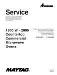
Service
MENUMASTER
COMMERCIAL
MICROWAVE
R
OVEN
This manual is to be used by qualified appliance
technicians only. Maytag does not assume any
responsibility for property damage or personal
injury for improper service procedures done by
an unqualified person.
1800 W - 2005
International
Countertop
Commercial
Microwave
Ovens
This Base Manual covers general information.
Refer to individual Technical Sheet
for information on specific models.
This manual includes, but is
not limited to the following:
DFS18E
RFS518S
UFS18E
URFS518S
P1330222M
P1330216M
P1330231M
P1330227M
16026086
April 2005
Important Information
Important Notices for Servicers and Consumers
Maytag will not be responsible for personal injury or property damage from improper service procedures. Pride and
workmanship go into every product to provide our customers with quality products. It is possible, however, that during
its lifetime a product may require service. Products should be serviced only by a qualified service technician who is
familiar with the safety procedures required in the repair and who is equipped with the proper tools, parts, testing
instruments and the appropriate service information. IT IS THE TECHNICIANS RESPONSIBILITY TO REVIEW ALL
APPROPRIATE SERVICE INFORMATION BEFORE BEGINNING REPAIRS.
!
WARNING
To avoid risk of severe personal injury or death, disconnect power before working/servicing on appliance to avoid
electrical shock.
To locate an authorized servicer, please consult your telephone book or the dealer from whom you purchased this
product. For further assistance, please contact:
Service Support Center
Contact your local product distributor or vist the Web site at www.amanacommercial.com.
Recognize Safety Symbols, Words, and Labels
! DANGER
DANGER—Immediate hazards which WILL result in severe personal injury or death.
!
WARNING
WARNING—Hazards or unsafe practices which COULD result in severe personal injury or death.
!
CAUTION
CAUTION—Hazards or unsafe practices which COULD result in minor personal injury, product or property
damage.
2
16026086
©2005 Maytag Services
Table of Contents
Important Information .................................................... 2
Important Safety Information .......................................4-8
Wiring ........................................................................ 8
Earthing Instructions .................................................. 8
Servicing of Earthing Products ................................... 8
General Information
Placement of the Oven ............................................... 9
Radio Interference ...................................................... 9
Earthing Instructions .................................................. 9
Microwave Oven Description ..................................... 10
Troubleshooting Procedures ................................... 11-16
Service information
Proper Handling of Magnetron Tubes ........................ 17
Magnetron Failure Modes ......................................... 17
Microwave Leakage Testing
Equipment ................................................................ 18
Procedure For Measuring Radiation Leakage ........... 18
Measurement With the Outer Panel Removed .......... 18
Measurement With a Fully Assembled Oven ............ 18
Record Keeping and Notification After Measurement 18
Troubleshooting
Operating Instructions for the Holaday
HI1501, HI1510, HI1710, and HI1801 ........................ 19
Testing Procedures ................................................. 20-23
©2005 Maytag Services
Disassembly Procedures
Disconnecting Wire Terminals .................................. 24
Outer Case ............................................................... 24
Door Assembly ......................................................... 25
Door Disassembly .................................................... 25
Control Panel ............................................................ 26
Interlock Switches .................................................... 26
High Voltage Capacitor ............................................. 27
Diode/Circuit Protector .............................................. 28
Transformer .............................................................. 28
Fuse / Fuse Block / Filter Assembly ........................ 28
Magnetron ................................................................ 28
Blower Motor ............................................................ 29
Splatter Shield .......................................................... 29
Top Antenna .............................................................. 29
Bottom Antenna ........................................................ 29
Top Stirrer Motor ....................................................... 29
Bottom Stirrer Motor ................................................. 29
Magnetron Thermal Cut-Out (TCO) ........................... 30
Cavity Thermal Fuse ................................................. 30
Tray Replacement ..................................................... 30
Oven Light Removal .................................................. 30
Appendix A
Quick Reference Guides ................................ A-2 – A-3
16026086
3
3
Important Safety Information
4
16020686
©2005 Maytag Services
Important Safety Information
©2005 Maytag Services
16026086
5
Important Safety Information
6
16020686
©2005 Maytag Services
Important Safety Information
!
CAUTION
Read the following information to avoid possible
exposure to microwave radiation:
The basic design of the Amana and Menumaster
microwave ovens make it an inherently safe device to
both user and servicer. However, there are some
precautions which should be followed when servicing the
microwave oven to maintain this safety. These are as
follows:
1. Always operate the unit from an adequately earthed
outlet. Do not operate on a two-wire extension cord.
2. Before servicing the unit (if unit is operable), perform
the microwave leakage test.
3. The oven should never be operated if the door does
not fit properly against the seal, the hinges or hinge
bearings are damaged or broken; the choke is
damaged, (pieces missing, etc.); or any other visible
damage can be noted. Check the choke area to
ensure that this area is clean and free of all foreign
matter.
4. If the oven operates with the door open and
produces microwave energy, take the following
steps.
A. Tell the user not to operate the oven.
B. Contact Maytag immediately.
5. Always have the oven disconnected when the outer
case is removed except when making the "live" tests
called for in this Service Manual. Do not reach into
the equipment area while the unit is energized.
Make all connections for the test and check them for
tightness before plugging the cord into the outlet.
6. Always earth the capacitors on the magnetron filter
box and H. V. Capacitor with an insulated-handle
screwdriver before working in the high voltage area
of the equipment compartment. Some types of
failures will leave a charge in these capacitors and
the discharge could cause a reflex action which
could make you injure yourself.
©2005 Maytag Services
7. In the area of the transformer, capacitor, diode, and
magnetron there is HIGH VOLTAGE. When the unit
is operating, keep this area clean and free of anything
which could possibly cause an arc or earthing, etc.
8. Do not for any reason defeat the interlock switches.
There is no valid reason for this action at any time;
nor will it be condoned by Maytag.
9. IMPORTANT: Before returning a microwave to a
customer, check for proper switch interlock action.
The primary and secondary switches MUST actuate
when the door is opened. The monitor switch MUST
close at a 1/64–inch (0.5 mm) when the door is
opened.
10. Before returning a microwave to a customer, verify the
door spacing is reasonably uniform along the top,
bottom, and sides, and that it measures
1
/64–inch (0.5 mm) or less.
11. The Amana or Menumaster microwave oven should
never be operated with:
• Any components removed and/or bypassed.
• Any of the safety interlocks found to be
defective.
• Any of the seal surfaces defective, missing,
or damaged.
12.To ensure that the unit does not emit excessive
microwave leakage and to meet the Department of
Health Human Service guidelines, check the oven
for microwave leakage using leakage monitor as
outlined in the instructions. The maximum leakage
level allowed is 4mW/cm2.
13.If servicer encounters an emission reading over
4 mw/cm2 the servicer is to cease repair and contact
the Maytag Service Department immediately for
further direction. Maytag will contact the proper
Government Agency upon verification of the test
results.
16026086
7
Important Safety Information
!
!
WARNING
Precautions to be observed before and during
servicing to avoid possible exposure to excessive
microwave energy, or electrical shock disconnect
power to oven.
WARNING
To avoid risk of electrical shock, personal injury or
death, make sure these earthing instructions are
followed.
(A) Do not operate or allow oven to be operated with
door open.
Earthing Instructions
(B) Make the following safety checks on all ovens to
be serviced before activating the magnetron or
other microwave source, and make repairs as
necessary:
• Interlock operation
• Proper door closing
• Seal and sealing surfaces (arcing, wear, and
other damage)
• Damage to or loosening of hinges and latches
• Evidence of dropping or abuse
(C) Before turning on microwave power for any service
test or inspection within the microwave generating
compartments, check the magnetron, waveguide or
transmission line, and cavity for proper alignment,
integrity, and connections.
(D) Any defective or misadjusted components in the
interlock, monitor, door seal, and microwave
generation and transmission systems shall be
repaired, replaced or adjusted by procedures
described in this manual before oven is released to
the consumer.
(E) Check microwave leakage to verify compliance with
the federal performance standard should be
performed on each oven prior to release to the
consumer.
!
WARNING
Do not remove earthing prong when installing earthed
appliance in a home or business that does not have
three wire earthing receptacle, under no condition is
earthing prong to be cut off or removed. It is the
personal responsibility of the consumer to contact a
qualified electrician and have properly earthed three
prong wall receptacle installed in accordance with
appropriate electrical codes
Should a two prong adapter plug be required temporarily,
it is the personal responsibility of the consumer to have it
replaced with properly earthed three prong receptacle or
the two prong adapter properly earthed by a qualified
electrician in accordance with appropriate electrical
codes.
Servicing of Earthed Products
The standard accepted color coding for earthing wires is
GREEN or GREEN WITH YELLOW STRIPE. These
earth leads are NOT to be used as current carrying
conductors. It is extremely important that the technician
replace any and all earths prior to completion of the
service call. Under no condition should earth wire be left
off causing a potential hazard to technicians and
consumer.
Wiring
Good service practice is to never route wiring over
terminals and/or sharp edges. This applies to any wiring
without regard to the circuit voltage. Wire insulation
material and thickness is designed and regulated for
electrical spacing purpose only, but cannot always be
relied upon because of possible cuts and/or abrasions,
which can occur during servicing.
8
16020686
©2005 Maytag Services
General Information
Placement of the Oven
Do not install microwave next to or above source of
heat, such as a deep fat fryer. This could cause the
microwave to operate improperly and could shorten the
life of electrical components.
Radio Interference
Microwave oven operation may cause interference to
radio, television, or similar equipment. Reduce or
eliminate interference by doing the following:
• Clean the door and sealing surfaces of microwave
oven according to instructions in “Care and
Cleaning” section.
• Place radio, television, etc. as far as possible from
the microwave oven.
• Use a properly installed antenna on radio,
television, etc. to obtain stronger signal reception.
Install microwave on a level countertop surface.
Do not block or obstruct oven filter. Allow access for
cleaning.
All air vents must be kept clear during cooking. If air
vents are covered during operation the oven may
overheat. In this case, a sensitive thermal safety device
automatically turns the oven off. The oven will be
inoperable until the oven has cooled sufficiently.
Earthing Instructions
This appliance MUST be earthed. If an electrical short
circuit occurs, earthing reduces the risk of electric shock
by providing an escape wire for the electric current. The
cord for this appliance has a earthing wire with a
earthing plug. Place the plug into an outlet that is
properly installed and earthed. Do not use a two–prong
adapter.
A
!
A
WARNING
To avoid risk of electric shock, personal injury or
death, do not alter the plug and use earthing plug
properly.
A
Consult a qualified electrician if you do not understand
the earthing instructions or if you wonder whether the
appliance is properly earthed.
Keep the electrical power cord dry and do not pinch or
crush it in anyway.
A—Allow at least 1½ inches / 3.81 centimeters of clearance
around top and sides of equipment. Proper air flow around
equipment cools electrical components. With restricted air
flow, oven may not operate properly and life of electrical
parts is reduced.
©2005 Maytag Services
The wires in the power cord are colored in accordance
with the following code:
16026086
• Green/Yellow:
• Blue:
• Brown:
Earth
Neutral
Live
9
General Information
Plug
Receptacle
Plug
Receptacle
230 V / 13 AMP
230 V / 16 AMP
Equipment requires a
230 VAC, 50 Hz, 13 amp power supply
Equipment requires a
230 VAC, 50 Hz, 16 amp power supply
Do not use a extension cord. If the product power cord is too short, have a qualified electrician install a
three-prong receptacle. This unit should be plug into a separate dedicated 230 VAC / 50 Hz power supply. If other
equipment is on the same circuit, an increase in cooking times may be required and fuse can be blown.
Microwave Oven Description
B
A
C
D
E
A—Window door screen
B—Spatter shields
C—Control panel (Electronic or Dial)
D—Door open button
E—Safety door lock system
10
16026086
©2005 Maytag Services
Troubleshooting Procedures
When you get a complaint from customers, evaluate the complaint carefully. If the following symptoms apply,
instruct the customer in the proper use of the microwave oven. This can eliminate an unnecessary service call.
!
CAUTION
•
•
•
•
Verify proper earthing before checking for trouble.
Be careful of the high voltage circuit.
Discharge the high voltage capacitor.
When checking the continuity of the switches or of the high voltage transformer, disconnect one lead wire from
these parts and then check continuity with the AC plug removed. To do otherwise may result in a false reading
or damage to your meter.
• Do not touch any part of the circuit on the controller, since static electric discharge may damage the control
panel. Always touch yourself to earth while working on this panel to discharge any static charge built up in your
body.
Condition
Microwave oven does not work.
Output power is too low.
Cause
• Inserting multiple plugs into
one outlet and using them at
the sam e tim e (blown fuse or
breaker).
• Microwave oven plug is not
inserted tightly.
• Low AC input voltage.
• Food temperature is too low.
Sparks occur.
Uneven cooking.
©2005 Maytag Services
• Using metallic ware and
allowing it to touch the oven
wall.
• Ceram ic ware trimmed in gold
or silver is used.
Inconsistent food thickness,
inconsistent fat or moisture
distribution within the food
products.
16026086
Remedy
• Avoid using other electrical
appliances when you use the
m icrowave oven.
• Insert m icrowave oven plug
securely.
• Use the m icrowave oven at
adequate line voltage.
• This may not be a defect. It is
possible that the food should
be cooked for a longer time
period.
• Do not use m etallic ware for
cooking.
• Do not use any type of
cookware with metallic
trimm ing.
• Use plastic wrap or lid.
• Stir once or twice while
cooking soup, cocoa, milk, etc.
11
Troubleshooting Procedures
Trouble 1: The following visual conditions indicate a probable failed control circuit.
1. Incomplete segments.
• Segment missing.
• Partial segment missing.
• Digit flickering (Note: Slight flickering is normal.)
2. Colon does not turn on or blink.
3. A distinct change in the brightness of one or more numbers in display.
4. One or more digits in the display are not lighting.
5. Display indicates a number different from one touched, for example, key in 5 and 3 appears in the display.
6. Specific numbers (for example 7 or 9) will not display when key pad is touched.
7. Display does not count down with time blinking or up with clock operation.
8. Display obviously jumps in time while counting down.
9. Display counts down too fast while cooking.
10.Each indicator light does not turn on after setting cooking cycle.
11. Display time of day does not reappear when cooking is finished.
12
Condition
No input can be
programmed.
Check
Check the connection
between keypad and
controller.
Result
• Continuity
• No continuity
1. Some inputs
cannot be
programmed.
2. Display shows
a number or
figure different
from one
touched.
3. Random
programming
when touching
other pads.
4. Display is fixed
at some figure
and can not
accept any
input.
Test keypad (see Testing
Procedure section).
• Results not as
specified.
• Results are
per
specifications.
16026086
Cause
• Failed
controller.
• Loose
connection.
• Failed
keypad.
Remedy
• Replace
controller.
• Repair
connection.
• Replace
keypad.
• Failed
controller.
• Replace
controller.
©2005 Maytag Services
Troubleshooting Procedures (Electronic Models)
Trouble 2:
Oven does not operate at all, display window does not display any digits, and
no input is accepted.
Fuse blows.
Check continuity
of monitor switch
with door closed.
Continuity
Malfunction
of the
monitor
switch.
Replace the fuse,
primary,
secondary, monitor
switches and
controller.
No
Continuity
Replace fuse
Check continuity
of primary switch
with door opened.
Continuity
Malfunction of
primary switch.
No
Continuity
Check continuity
of secondary
switch with door
opened.
Continuity
Malfunction of
secondary
switch.
No
Continuity
Disconnect one side of
the wire lead connecting
transformer to high
voltage capacitor and
operate the unit.
Fuse blows
again.
Abnormal
Normal
Fuse does not
blow.
Continuity
©2005 Maytag Services
Measure
resistance of high
voltage capacitor.
Check continuity
of thermostat
(cavity and
magnetron).
Check continuity
of power cord.
No
Continuity
16026086
Replace the fuse,
primary,
secondary, monitor
switches and
controller.
Failed high
voltage
transformer.
Replace high
voltage
transformer.
Failed high
voltage
capacitor.
Replace high
voltage
capacitor.
Capacitor is good,
(replace fuse only).
Normal
No
Continuity
Replace the fuse,
primary,
secondary, monitor
switches and
controller.
Failed
thermostat.
Failed power
cord.
Replace
thermostat.
Replace
power cord.
13
Troubleshooting Procedures (Electronic Models)
Trouble 3:
Display shows all digits programmed, but does not start cooking when the
START pad is pressed.
Check continuity
of secondary
switch with door
closed.
Time does not
count down
after START
pad is pressed.
No
Continuity
Malfunction
of secondary
switch.
Replace the
secondary
switch.
Continuity
Check connection
between CN1
connector and
controller.
Continuity
Failed
controller.
Replace
controller.
No
Continuity
Loose
connection.
Repair
connection.
Normal
Fan motor or
oven light does
not operate.
Check fan
motor.
Abnormal
Failed fan
motor.
Replace fan
motor.
Check oven
light.
Abnormal
Failed oven
light.
Replace oven
light.
Normal
14
16026086
©2005 Maytag Services
Troubleshooting Procedures (Electronic Models)
Trouble 4:
Oven operates with little or no heat.
Output
performance
is low.
Check the power
supply voltage.
Lower than
90% of rated
voltage.
Decrease in
supply voltage
under load.
Normal
Disconnect wire leads
from relay RY3 and RY5
Verify on and off times.
Abnormal
Failed
controller.
Customer must
contact local
power
company or
qualified
electrician.
Replace
controller.
Normal
Measure the
output power.
Abnormal
Failed
magnetron
Replace
magnetron.
NOTE: Simple output power test can be conducted by heating one liter of water for 33 seconds.
Refer to Power Test on page 23 of this manual.
Check for continuity of relay 3 with an omhmeter.
(Remove wire leads from relay 3 and operate unit.)
Power Level Cycle ON
1
3 sec.
2
4 sec.
3
5 sec.
4
6 sec.
5
7 sec.
6
8 sec.
7
9 sec.
8
10 sec.
9
11 sec.
10
12 sec.
©2005 Maytag Services
Cycle OFF
9 sec.
8 sec.
7 sec.
6 sec.
5 sec.
4 sec.
3 sec.
2 sec.
1 sec.
0 sec.
16026086
15
Troubleshooting Procedures (Electronic Models)
Trouble 5:
No microwave oscillation even when oven light and fan motor operate.
No microwave
oscillation.
Disconnect wire
leads from relay
RY3 and RY5.
Verify continuity
Of the relay.
No
Continuity
Check high
voltage
transformer.
Abnormal
Failed
controller.
Replace
controller.
Continuity
Failed high
voltage
transformer.
Replace high
voltage
transformer.
Failed high
voltage
capacitor.
Replace high
voltage capacitor.
Normal
Check high
voltage capacitor.
Abnormal
Normal
Check high voltage
diode.
Abnormal
Failed high
voltage
diode.
Replace high
voltage diode.
Normal
Abnormal
Failed
magnetron.
Abnormal
Failed
controller.
Check magnetron.
Operates at
full power
when
programmed
for lower
power.
16
Disconnect wire
leads from relay
RY3 and RY5.
Verify continuity
Of the relay.
16026086
Replace
magnetron.
Replace
controller.
©2005 Maytag Services
Service Information
!
WARNING
To avoid risk of electrical shock, personal injury, or death, disconnect power to oven and discharge capacitor
before servicing, unless testing requires power.
Proper Handling of Magnetron Tubes
!
CAUTION
A magnetron tube, like a radio or television tube
must be handled with a reasonable amount of care.
When handling a tube, always handle by the housing
only. Use caution not to touch or strike the ceramic
portion at the top. The carton used to ship service
replacement tubes is reusable.
Magnetron Failure Modes
Magnetron failures that have been identified are
generally grouped into categories shown below.
1. Shorted
Air - This is a case where the tube has had the vacuum
envelope destroyed and air has entered the tube.
This will cause internal arcing and high secondary
current if high voltage is applied.
2. Open Heater (Filament) - Can be determined by a
ohmmeter when transformer leads are
disconnected. Resistance is normally less than one
ohm; filament does not short internally. Any tube
removed should be checked since usage tends to
make the filament more fragile. Later handling and
shipping may open the filament and thereby mask
the true failure mode when checked at the factory.
3. Low Power - Caused by “wearout” of the emission
characteristics of the directly heated cathode.
Symptoms are: (1) tube current will take longer to
get to operating point than a new tube (normally
about 2 - 3 seconds), (2) tube current does not get
high enough to cause the tube to oscillate with
normal line voltage, (3) oven produces low power
into a load, two-thirds or less than normal.
4. Physical Damage - Caused by mishandling of
magnetron tube.
R.F. Capacitors - May short to chassis. This condition
will also cause loss of high voltage.
Output
Antenna
Ceramic
Fins
Anode
Block
Magnet
Terminals/R.F. Capacitors
Not Replaceable
Serial Number
©2005 Maytag Services
16026086
17
Microwave Leakage Testing
!
WARNING
To avoid risk of electrical shock, personal injury, or death, disconnect power to oven and discharge capacitor
before servicing, unless testing requires power.
!
Measurement with the Outer Panel
Removed
WARNING
Check for radiation leakage after servicing. Should the
leakage be more than 4 mW/cm2 inform Maytag
immediately. After repairing or replacing any radiation
safety device, keep a written record for future reference,
as required by D.H.H.S. and HEW regulations. This
requirement must be strictly observed. In addition, the
leakage reading must be recorded on the service repair
ticket while in the customer’s home.
Equipment
• Electromagnetic radiation monitor
• 600 cc glass beaker or plastic power bowl
!
WARNING
Avoid contacting any high voltage components.
Whenever you replace the magnetron, measure for
radiation leakage before the outer panel is installed
and after all necessary components are replaced or
adjusted. Special care should be taken in measuring
around the magnetron.
Measurement with a Fully Assembled
Oven
Procedure for Measuring Radiation Leakage
Note before measuring:
• Do not exceed meter full scale deflection. Leak monitor
should initially be set to the highest scale.
• To prevent false readings the test probe should be held
by the grip portion of the handle only.
• The scan speed is equal to one inch per antenna
revolution or one inch per second if antenna speed is
unknown.
• Areas to be checked are all door seal areas and any
venting parts.
• Leakage with the outer panel removed ...4mW/cm2 or
less.
• Leakage for fully assembled oven with door normally
closed ...4 mW/cm2 or less.
• Leakage for a fully assembly oven (before the latch
switch (primary) is interrupted) while pulling the door
... 4 mW/cm2 or less.
After all components including the outer panel are fully
assembled, measure for radiation leakage around the
door periphery, the door viewing window, the exhaust
opening, and air inlet openings.
Record Keeping and Notification After
Measurement
1. After any adjustment or repair to a microwave
oven, a leakage reading must be taken. Record
this leakage reading on the repair ticket even if it is
zero.
2. A copy of the repair ticket and the microwave
leakage reading should be kept by the repair
facility.
1. Pour 275 cc ±15 cc (9 oz ±1/2 oz) of 20°C ± 5°C
(68°F ± 9°F) water in a beaker which is graduated to
600 cc and place the beaker in the center of oven.
2. Set the radiation monitor to 2450 MHz and use it
following the manufacturer’s recommended test
procedure to assure correct results.
3. While measuring the leakage, always use the two inch
(5 cm) spacer supplied with the probe.
4. Press the start pad or turn on the timer and with the
magnetron oscillating, measure the leakage by holding
the probe perpendicular to the surface being
measured.
18
16026086
©2005 Maytag Services
Troubleshooting
!
WARNING
To avoid risk of electrical shock, personal injury, or death, disconnect power to oven and discharge capacitor
before servicing, unless testing requires power.
Operating Instructions for the Holaday
HI1501, HI1510, HI1710, and HI1801
Purpose of these monitors is to check radiation
leakage around microwave oven door or other places
where radiation could possibly occur.
Instrument measures radiation leakage in milliwatts
per square centimeters (mW/cm2). Probe should be
used with the 2" (5 cm) cone spacer. Water load of
1
275 cc. (approximately 1 /3 cup), is to be placed in
the oven and used as a load during leakage tests.
Operate the instrument on its internal 9 Volt battery
power supply. “Range” switch is used on low and high
while using test probe. On an oven with an unknown
leakage, use high scale then switch to low scale and
test for low leakage. “Bat Test” switch is used to
check the battery and probe on the Holaday
Instruments. If either is faulty, meter needle will not
read above “Test Minimum” or battery mark on meter.
Holaday Instrument has a probe test switch position.
Meter needle must indicate in the “OK probe test”
portion of the scale when in this position. Zero control
is used to zero the needle. “ON-OFF” switch provides
a means of turning the operating voltage on or off.
“Range Multiplier” switch provides a means of
selection either 0-2 or 0-10 and 0-100 on the Holaday
Instruments sensitivity ranges.
Hold probe perpendicular to cabinet door. Place cone
of probe on the door and/or cabinet door seam and
move along the seam. If leakage of the oven is
unknown, move probe slowly. Proceed with care in
order not to exceed a full scale reading of meter.
When testing near a corner or access area of door,
keep probe perpendicular to the areas making sure
probe end at the base of the cone does not get closer
than 2” (5cm) to any metal. If it does, an erroneous
reading may result.
Always use the 2” (5cm) spacer with probe. Also,
always proceed carefully in areas of high leakage or
probe can be accidentally burned-out. Rotating
antenna causes high peaks of energy. Although meter
has averaging capabilities, probe will react
instantaneously to peak power changes which will
cause burn-out.
Test probe must be held by the grip portion of the
handle, otherwise a false reading may result if
operators hand is between the handle and probe.
If oven is likely to have a large amount of leakage,
approach oven slowly with the probe, while observing
meter. This is achieved by holding the probe two or
three feet from oven surface or gap between door and
oven body while observing meter. When high leakage
is expected, do not move probe horizontally along the
oven surface. This could cause possible probe
burn-out. Greatest leakage is generally found at the
corners. After maximum leakage is established to be
within the meter scale range, then probe may be
moved horizontally around the door surface.
©2005 Maytag Services
16026086
19
Testing Procedures
!
WARNING
To avoid risk of electrical shock, personal injury or death; disconnect power to oven and discharge capacitor
before servicing, unless testing requires power.
Illustration
Component
Thermal cutout
Testing
Disconnect all wires from TCO.
Measure resistance across terminals.
Cavity TCO............................................
Magnetron TCO.....................................
Diode
Discharge Capacitor
Remove diode lead from capacitor and
connect ohmmeter.
Circuit Protector
Reverse leads for second test.
Discharge Capacitor
Remove diode lead from capacitor and
connect ohmmeter.
Reverse leads for second test.
Capacitor
Closed at 32°F (0°C) and
Opens at 230°F (110°C)
Closed at 140°F (60°C) and
Opens at 320°F (160°C)
Infinite resistance should be
measured in one direction and 50KΩ
or more in the opposite direction.
NOTE: Ohmmeter must contain a
battery of 6 volts minimum.
Infinite resistance should be
measured in one direction and 50KΩ
or more in the opposite direction.
NOTE: Ohmmeter must contain a
battery of 6 volts minimum.
Discharge Capacitor
Remove wires from capacitor terminals
and connect ohmmeter, set on highest
resistance scale to terminals.
Magnetron
Results
Also check between each terminal and
capacitor case.
Discharge Capacitor
Remove wires from magnetron and
connect ohmmeter to terminals. Also
check between each terminal and
ground.
Between Terminals: Meter should
momentarily deflect towards zero
then return to over 5 MΩ. If no
deflection occurs, or if continuous
deflection occurs, replace capacitor.
Terminal to Case: Infinite resistance
Between Terminals: Less than 1 Ω
Each terminal to ground measures
Infinite resistance.
Note: This test is not conclusive. If
oven does not heat and all other
components test good replace the
magnetron and retest.
Blower motor
Remove all wires from motor.
Measure resistance across coil .............
Remove all wires from motor.
Approximately 40 – 44 Ω
Stirrer motor
Measure resistance across terminals ....
Discharge Capacitor
Remove all wires from terminals.
Approximately 12.8 – 13.5 KΩ
Transformer
Secondary
Filament
Primary
Noise filter board
20
Measure resistance from:
Primary ................................................
Filament ...............................................
Secondary to Ground screw on
transformer stack .................................
Power In terminals.................................
Power Out terminals ..............................
Lamp receptacle
Test continuity of receptacle terminals.
Wire Harness
Test continuity of wires
16026086
Less than <1 Ω
Less than <1 Ω
Approximately 121 – 128 Ω
230/240 VAC
230/240 VAC
If no power in, check power outlet.
If no power out, check fuses.
Indicates continuity with bulb
installed.
Indicates continuity
©2005 Maytag Services
Testing Procedures
!
WARNING
To avoid risk of electrical shock, personal injury or death; disconnect power to oven and discharge capacitor
before servicing, unless testing requires power.
Illustration
Component
Interlock switch assembly
3
Monitor
4
1
2
5
Primary
6
Secondary
Electronic Control Panel
Service Test Mode:
Testing
Disconnect wires to switch.
Results
With door open measure resistance from:
Monitor - Terminal 3 - 4..........................
Primary - Terminal 1 - 2 .........................
Secondary - Terminal 5 - 6.....................
Indicates continuity
Infinite Ω
Infinite Ω
With door closed measure resistance from:
Monitor - Terminal 3 - 4..........................
Primary - Terminal 1 - 2 .........................
Secondary - Terminal 5 - 6.....................
Infinite Ω
Indicates continuity
Indicates continuity
After verifying or replacing the module,
reconnect wires to switch and check
operation of monitor circuit before
operating the oven.
Open door, Press and Hold pad 3 for 5
seconds to enter service test mode.
Press Pad 1 ................................................
Press Pad 2 ................................................
Press Pad 3 ................................................
Press Pad 4 ................................................
Press Pad 5 ................................................
Press Pad 6 ................................................
Error codes:
Illustration
Electronic Control
DFS18E
RFS518S
UFS18E
URFS518S
©2005 Maytag Services
Component
Keyboard assembly
Press Pad 7 ................................................
Press Pad 8 ................................................
Press Pad 9 ................................................
Press Pad 0 ................................................
Stop/Reset Pad ...........................................
E-08 ............................................................
E-09 ............................................................
E-10 ............................................................
Testing
Continuity is indicated as
100 Ω and below.
1
2
3
4
5
6
7
8
9
10
11
16026086
SERVICE appears in the display
Indicates number of hours
magnetron has been turned on
Indicates number of times
magnetron tube has been turned
on and off
Indicates number of door cycles
CLEAR (Press START pad to
reset service data.)
Indicates amperage (Top Mag)
Indicates amperage (Bottom
Mag)
RESET (Call Service)
N/A
N/A
N/A
Exit Service Test Mode
Replace Control Board
Replace Control Board
Shorted or Open Keypad – Test
and replace if necessary
Pad
0
1
2
3
4
5
6
7
8
9
QTY 2X
HOLD (0%)
DEFROST (20%)
MEDIUM (50%)
MED-HI (70%)
TIME ENTRY
STOP/RESET
START
Results
Trace
1&8
2&8
3&8
4&8
5&8
6&8
7&8
1&9
2&9
3&8
7&9
1 & 10
2 & 10
3 & 10
4 & 10
5 & 10
6 & 10
7 & 10
Measurement
Continuity
Continuity
Continuity
Continuity
Continuity
Continuity
Continuity
Continuity
Continuity
Continuity
Continuity
Continuity
Continuity
Continuity
Continuity
Continuity
Continuity
Continuity
21
Testing Procedures
!
WARNING
To avoid risk of electrical shock, personal injury or death; disconnect power to oven and discharge capacitor
before servicing, unless testing requires power.
RY3
2 1
2 1
RY5
TAB 1
TAB 2
9 8
5 4 3
1
CN1
Function
Control power
transformer input
Current transformer
input
Current transformer
output
Oven light
relay RY7
Blower / Stirrer motor
relay RY1
Secondary Interlock
Switch
Cook relay
RY3
Cook relay
RY5
22
Test Set-Up /
Condition
All Conditions
Meter
Setting
Volts
Probe Placement
CN1 – Pin 3 to Pin 1 (White to Black)
230/240 VAC
All Conditions
Volts
Tab 1 to Power Cord Blue (Neutral)
230/240VAC
All Conditions
Volts
Tab 2 to Power Cord Blue (Neutral)
230/240VAC
Standby .............
Ready................
Cook..................
Standby .............
Ready................
Cook..................
Door Closed ......
Door Opened ....
Volts
Volts
Volts
Volts
Volts
Volts
Ohms
Ohms
CN1 – Pin 4 to Pin 1 (Yellow to Black)..
CN1 – Pin 4 to Pin 1..............................
CN1 – Pin 4 to Pin 1..............................
CN1 – Pin 5 to Pin 3 (Brown to White)..
CN1 – Pin 5 to Pin 3..............................
CN1 – Pin 5 to Pin 3..............................
CN1 – Pin 8 to Pin 9 (Pink to Green) ....
CN1 – Pin 8 to Pin 9..............................
0 VAC
230/240VAC
230/240VAC
230/240VAC
0 VAC
0 VAC
<1
Infinite
Standby .............
Ready................
Cook..................
Standby .............
Ready................
Cook..................
Volts
Volts
Volts
Volts
Volts
Volts
Relay 3 – Pin 1 to Pin 2.........................
Relay 3 – Pin 1 to Pin 2.........................
Relay 3 – Pin 1 to Pin 2.........................
Relay 5 – Pin 1 to Pin 2.........................
Relay 5 – Pin 1 to Pin 2.........................
Relay 5 – Pin 1 to Pin 2.........................
230/240VAC
230/240VAC
0 VAC
230/240VAC
230/240VAC
0 VAC
16026086
Results
©2005 Maytag Services
Testing Procedures
!
WARNING
To avoid risk of electrical shock, personal injury or death; disconnect power to oven and discharge capacitor
before servicing, unless testing requires power.
Power Test
All Amana and Menumaster microwave oven power outputs are rated using the IEC705 standards. Using the IEC705
test method requires precision measurements and equipment that is not practical to be performed in the field. Using
the test shown below will indicate if the oven performance is satisfactory.
Test equipment required:
•
•
1000 ml test container and thermometer (Amana power test kit R0157397 Fahrenheit / Menumaster power
test kit M95D5 Celsius).
Digital watch / watch with a second hand for use on ovens with electromechanical timers.
Important Notes:
•
•
•
Low line voltage will cause low temperature rise / power output.
Ovens must be on a dedicated circuit, properly grounded, and polarized. Other equipment on the same
circuit may cause a low temperature rise / power output.
This test and results are not a true IEC705 test procedure and are only intended to provide servicers with an
easy means of determining if the microwave oven cooking output is correct.
Procedure
1. Fill the test container to the 1000 ml line with cool tap water.
NOTE:
Water temperature should be approximately 60°F / 16°C
2. Using the thermometer, stir water for five to ten seconds; measure, and record the temperature (T1).
3. Place test container of water in the center of oven cavity and close door.
4. Heat the water for a 33-second full power cycle.
NOTE:
Use a digital watch or a watch with a second hand for ovens with electromechanical timers.
1. At end of the cycle, remove test container. Using the thermometer, stir water for five to ten seconds and record
temperature (T2).
2. Subtract the starting water temperature (T1), from the ending water temperature (T2) to obtain the temperature
rise (∆T).
3. If the temperature rise (∆T) meets or exceeds the minimum, the test is complete. If the temperature rise (∆T)
fails to meet the minimum temperature rise, test the line voltage to verify it is correct. Then repeat steps 1-6
making sure to change the water. If the temperature rise (∆T) fails to meet the minimum temperature rise again
the oven will require service.
Minimum Temperature Rise at Thirty -Three (33) Seconds Run Time
∆T
(°F)
Cooking
Power Output
10 .................1000
11 .................1100
12 .................1200
14 .................1400
17 .................1700
18 .................1800
19 .................1900
©2005 Maytag Services
∆T
(°F)
Cooking
Power Output
20 ................. 2000
21 ................. 2100
22 ................. 2200
24 ................. 2400
25 ................. 2500
27 ................. 2700
30 ................. 3000
16026086
∆T
(°C)
Cooking
Power Output
5 ............... 1000
5.5............. 1100
6.5............. 1200
7.5............. 1400
9.5............. 1700
10.............. 1800
10.5........... 1900
∆T
(°C)
Cooking
Power Output
11 ............ 2000
11.5 ......... 2100
12 ............ 2200
13 ............ 2400
13.5 ......... 2500
15 ............ 2700
16.5 ......... 3000
23
Disassembly Procedures
!
To avoid the risk of electrical shock, personal injury, or death,
disconnect power to oven and discharge the capacitors before
following any disassembly procedure.
WARNING
High voltage is present at the high voltage terminal of the
high voltage transformer during any cooking cycle.
It is neither necessary or advisable to attempt
measurement of the high voltage.
Before touching any oven components or wiring, always
unplug the oven from its power source and discharge
capacitor.
Outer Case
1.
2.
3.
4.
Disconnect power to oven.
Remove screws securing outer case to unit.
Slide outer case towards rear of unit.
Reverse procedure to reassemble.
Disconnecting Wire Terminals
All wire terminals are locking-type terminals.
Proceed as follows to disconnect wire terminals:
Insulated terminals:
Grasp insulator pod and pull back.
DO NOT PULL ON WIRE.
1 Grasp
Insulator
Pod
Wire
2 Pull
Non-insulated terminals:
Use a small blade screwdriver to depress locking-tab and
pull on terminal.
DO NOT PULL ON WIRE.
1 Release
locking-tab
!
CAUTION
During disassembly some foam gaskets may require
removal. These components must be replaced for
proper circulation of air over the components and
through the oven cavity.
Wire
2 Pull
24
16026086
©2005 Maytag Services
Disassembly Procedures
!
To avoid the risk of electrical shock, personal injury, or death,
disconnect power to oven and discharge the capacitors before
following any disassembly procedure.
WARNING
Door Assembly
!
!
CAUTION
A microwave leakage test must be performed anytime
a door assembly is removed, replaced, disassembled,
or adjusted for any reason.
Door Removal
1. Disconnect power to oven.
2. Open oven door, remove top hinge cap, and slowly lift
door to disengage the hinge pins at top and bottom.
CAUTION
To avoid property damage, care must be taken when
prying choke cover from oven door.
4. Remove screw securing door handle to latch
assembly.
5. Slide latch assembly downward and pull away from
door frame to release.
6. Remove screws securing choke assembly to outer
door panel.
NOTE: When disassembling door, use caution to
prevent deformation of slats on door frame/choke
assembly.
Top hinge cap
7. Begin at hinge side of door near bottom, insert flat
blade screwdriver between door frame/choke
assembly and outer door panel. Gently pry outer door
panel away from door frame to release tabs. Work in
clockwise direction to remove door frame.
8. Remove spring from hinge assembly.
9. Remove screws securing hinge assembly to choke
assembly.
10. Reassemble in reverse order.
Choke
cover
3. To reinstall door, place top pin into slot first, then align
bottom pin.
4. Reinstall top hinge cap.
Top
hinge
cap
Outer
Door
panel
Latch
assembly
Spring
Door frame/
choke assembly
Door
Handle
* Tighten side screw first and apply Loctite
Door Disassembly
1. Disconnect power to oven.
2. Remove oven door, (see "Door Removal").
3. Begin at the bottom of the door near hinge, insert flat
blade screwdriver between choke cover and outer door
panel. Gently pry upward on choke cover to release
tabs. Work in clockwise direction to remove choke
cover.
©2005 Maytag Services
!
CAUTION
A microwave leakage test must be performed anytime
a door assembly is removed, replaced, disassembly, or
adjusted for any reason.
16026086
25
Disassembly Procedures
!
WARNING
To avoid the risk of electrical shock, personal injury, or death,
disconnect power to oven and discharge the capacitors before
following any disassembly procedure.
Control Panel
Interlock Switches
1. Disconnect power to oven and remove outer case,
(see "Outer Case" procedure).
2. Disconnect and label wires from controller/timer.
3. Open oven door.
4. Remove screw securing top of control panel to cavity.
Lift control panel up and out to release tabs.
Primary switch is operated by bottom latch arm.
Interlock Switch Removal
1. Disconnect power to oven and remove outer case,
(see "Outer Case" procedure).
2. Remove control panel, (see "Control Panel" section).
3. Test interlock switches before removing, (see testing
procedures).
4. Disconnect and label wire connections.
5. Remove mounting screws securing interlock switch to
unit chassis.
6. Replace component and reverse procedure to
reassemble.
Tab
NC
Monitor
Switch
COM
NO
Primary
Switch
COM
Secondary
Switch
5. Replace component and reverse procedure to
reassemble.
NO
COM
Tab
NOTE: After repairing the door or the interlock system, it
is necessary to check the switch continuity
before operating the oven.
!
CAUTION
Before replacing a blown monitor fuse, test the primary
interlock switch, secondary interlock switch, monitor
switch, and power relay contacts for proper operation.
If the monitor fuse is blown by a failed switch
operation, all switches and controller must be
replaced.
26
16026086
©2005 Maytag Services
Disassembly Procedures
!
To avoid the risk of electrical shock, personal injury, or death,
disconnect power to oven and discharge the capacitors before
following any disassembly procedure.
WARNING
Adjusting Interlocks
The interlock monitor, primary, and secondary switches
act as a final safety switch, protecting the operator from
microwave energy. After adjusting the interlock switch
assembly, verify wires are correctly connected.
For door fit and switch operation, switch bracket is
adjustable.
1. Disconnect power to oven and remove outer case,
(see "Outer Case" procedure).
2. Loosen switch bracket mounting screws.
3. Close oven door, move switch bracket toward rear of
oven until door gap is less than 1/64–inch (0.5 mm).
4. Hold switch bracket securely for proper switch
operation and door fit, retighten screws.
5. Open oven door slowly, watching the switches. Verify
switches release in the following order.
• Primary interlock switch
• Secondary interlock switch
• Interlock monitor switch
Bottom Magnetron High Voltage Capacitor Removal
1. Disconnect power to oven and remove outer case,
(see "Outer Case" procedure).
2. Discharge high voltage capacitor.
3. Remove and label wire leads from capacitor terminals.
4. Remove screw securing diode to ground.
5. Remove screw securing capacitor strap to the back
panel, located on the back panel.
6. Slide capacitor out of capacitor strap and remove
capacitor.
7. Replace capacitor and reverse procedure to
reassemble.
NOTE: When replacing H.V. components, route H.V.
wires at least 1/4" / 6 mm from all grounded
surfaces to prevent arcing.
NOTE: Adjust the switch bracket until all switches
operate in proper sequence.
6. Close the oven door slowly, watching the switches.
Verify switches activate in the following order.
• Interlock monitor switch
• Secondary interlock switch
• Primary interlock switch
7. When proper switch sequence has been achieved,
tighten the switch bracket securely.
!
CAUTION
A microwave leakage test must be performed anytime
a door assembly is removed, replaced, disassembled,
or adjustment of switch bracket is performed.
High Voltage Capacitor
High voltage capacitor should always be discharged by
shorting a terminal to a chassis ground. The capacitor
has a internal "shunt" resistor, but the mechanical
discharge should always be performed to avoid personal
injury.
©2005 Maytag Services
Top Magnetron High Voltage Capacitor Removal
1. Disconnect power to oven and remove outer case,
(see "Outer Case" procedure).
2. Discharge high voltage capacitor.
3. Remove and label wire leads from capacitor terminals.
4. Remove screw securing diode to ground.
5. Remove screw securing top portion of capacitor strap
to the top of the oven cavity.
6. Remove screw securing control panel to chassis.
7. Raise control panel upward and rotate to the side to
gain access to capacitor bottom mounting screw.
8. Remove screw securing bottom portion of capacitor
strap to the duct assembly.
9. Slide capacitor out of capacitor strap and remove
capacitor.
10. Replace capacitor and reverse procedure to
reassemble.
16026086
27
Disassembly Procedures
!
To avoid the risk of electrical shock, personal injury, or death,
disconnect power to oven and discharge the capacitors before
following any disassembly procedure.
WARNING
Diode/Circuit Protector
1. Disconnect power to oven and remove outer case,
(see "Outer Case" procedure).
2. Discharge high voltage capacitor, (see "High Voltage
Capacitor" section).
3. Disconnect component from high voltage capacitor
and remove screw securing diode to ground.
4. Replace component and reverse procedure to
reassemble.
Transformer
1. Disconnect power to oven and remove outer case,
(see "Outer Case" procedure).
2. Discharge high voltage capacitor, (see "High Voltage
Capacitor" section).
3. Disconnect and label wire leads from transformer.
4. Place unit on it's back to gain access to mounting
screws.
5. Remove screws securing transformer and remove.
6. Replace transformer and reverse procedure to
reassemble.
Blower Motor ASS'Y
2. Disconnect and label wires.
3. Carefully lift tabs to release assembly from plastic
locating pins.
4. Replace component(s) and reverse procedure to
reassemble.
!
CAUTION
Before replacing a blown monitor fuse, test the primary
interlock switch, secondary interlock switch, monitor
switch, and power relay contacts for proper operation.
If the monitor fuse is blown by a failed switch
operation, all switches and controller must be
replaced.
Magnetron
Magnetrons are located on the side of the cavity.
1. Disconnect power to oven and remove outer case,
(see "Outer Case" section).
2. Discharge high voltage capacitor, (see "High Voltage
Capacitor" section).
3. Remove terminal plug from filament terminals.
4. Remove screws securing duct assembly and place to
the side to gain access to magnetrons.
5. Remove screws securing magnetron being replaced to
the wave guide.
Antenna
Gasket
Suction
Guide
Chassis
H.V
Filament
H.V
Transformer
H.V
Transformer
6. Replace magnetron and reverse procedure to
reassemble.
NOTE: When replacing magnetron, make sure gasket is
in correct position and in good condition.
!
CAUTION
During replacement of magnetron, be certain the R.F.
anode gasket is in place around the anode stud.
Fuse / Fuse Block / Filter Assembly
1. Disconnect power to oven and remove outer case,
(see "Outer Case" section).
28
!
WARNING
A microwave leakage test must be performed anytime
a magnetron assembly is removed, replaced,
disassembled, or adjusted for any reason.
16026086
©2005 Maytag Services
Disassembly Procedures
!
To avoid the risk of electrical shock, personal injury, or death,
disconnect power to oven and discharge the capacitors before
following any disassembly procedure.
WARNING
Blower Motor
Top Antenna
1. Disconnect power to oven and remove outer case,
(see "Outer Case" procedure).
2. Remove outer case.
3. Disconnect wiring from blower motor.
4. Remove screws securing duct assembly to unit.
5. Remove screws securing blower motor assembly to
duct assembly and back panel.
6. Remove screws securing blower motor and slide
blower motor out from the unit.
7. Replace component and reverse procedure to
reassemble.
1. Disconnect power to oven.
2. Remove splatter shield from oven cavity.
3. Remove two mounting rivets on the top of oven cavity
to remove cradle. Support cradle before removing
mounting rivets to avoid damage to antenna
assembly.
4. Replace component and reverse procedure to
reassemble.
Bottom Antenna
1. Disconnect power to oven.
2. Remove oven tray, see "Tray Replacement"
procedure.
3. Remove two mounting rivets on the top of oven cavity
to remove cradle. Support cradle before removing
mounting rivets to avoid damage to antenna
assembly.
4. Replace component and reverse procedure to
reassemble.
Top Stirrer Motor
Splatter Shield
NOTE: Be careful not to bend antenna when removing
splatter shield. Shield snaps into a lip in front of
the oven and three slots in the back.
1. Place your thumbs in the two indentations in front of
the shield.
2. Press lightly towards the back and carefully lower
shield away from antenna.
3. Pull shield out of the back slots and out of the oven.
1. Disconnect power to oven and remove outer case,
(see "Outer Case" procedure).
2. Remove outer case.
3. Disconnect wire terminals from stirrer motor.
4. Remove screws securing stirrer motor to wave guide.
5. Replace component and reverse procedure to
reassemble.
NOTE: When replacing stirrer motor, verify motor shaft is
aligned with antenna shaft before securing with
screws.
Bottom Stirrer Motor
1.
2.
3.
4.
5.
Unplug oven and place unit on its back panel.
Removing screw securing bottom access panel.
Disconnect wire terminals from stirrer motor.
Remove screws securing stirrer motor to chassis.
Replace component and reverse procedure to
reassemble.
Splatter
shield
©2005 Maytag Services
16026086
29
Disassembly Procedures
!
To avoid the risk of electrical shock, personal injury, or death,
disconnect power to oven and discharge the capacitors before
following any disassembly procedure.
WARNING
Magnetron Thermal Cut-Out (TCO)
Oven Light Removal
1. Disconnect power to oven and remove outer case,
(see "Outer Case" procedure).
2. Remove outer case.
3. Remove screw securing bottom portion of duct
assembly securing bottom TCO.
4. Bend metal tab securing top TCO located above top
magnetron.
5. Disconnect and label wiring.
6. Replace component and reverse procedure to
reassemble.
The light bulb for inside of the oven can be changed only
from the side of the unit. On the left hand side of the oven
is a metal plate with one screw. The light bulbs are
located behind this plate.
NOTE: When reconnecting wiring to thermal fuses the
connectors must be tight.
Cavity Thermal Fuse
1. Disconnect power to oven and remove outer case,
(see "Outer Case" procedure).
2. Remove outer case.
3. Remove screw securing cavity thermal fuse.
4. Disconnect and label wiring.
5. Replace component and reverse procedure to
reassemble.
NOTE: When reconnecting wiring to thermal fuses the
connectors must be tight.
Tray Replacement
1. Unplug oven from outlet.
2. Using a suction cup to pry upward on front portion and
remove tray from unit.
3. Thoroughly clean and degrease sump area.
4. Clean oven cavity bottom where new oven tray will
make contact using mineral spirits or any
non-flammable degreasing solvent.
Follow these steps to change the bulb:
1. Disconnect power to oven.
2. Remove screw and plate from side of unit.
3. To remove bulb, turn it counterclockwise, being
careful not to burn fingers or break the bulb.
4. Replace bulb with a 20 watt, 230 - 240 volt appliance
bulb.
5. Reposition plate, being careful not to bend hinge tab.
Replace and tighten screw. Do not operate oven
without plate in place.
NOTE: Detergents, soap, and water are not sufficient to
remove oil and grease.
5. Clean cavity with mild detergent to remove any
remaining degreasing solvent and place new tray into
unit.
30
16026086
©2005 Maytag Services
Appendix A
©2005 Maytag Services
16026086
A–1
Quick Start Reference Guide
Refer to Product Safety Manual for Safety Statements
CLEAN FILTER
This oven displays CLEAN FILTER at user
defined intervals. When the message
displays Amana recommends cleaning
the air filter thoroughly. Cleaning the air
filter will not shut off the message.
The message will stop displaying
automatically after 24 hours. Depending
on microwave use and environmental
conditions, the filter may need to be
cleaned more frequently. Once the
frequency is determined, set the option
for the appropriate time frame.
Complete Owner’s Manual available online
Oven Wall Clearances
A
B
C
A—For North American (UL/CSA) models, allow at least
2” (5.1 cm) of clearance around top of oven. For
International (50 Hz) models, allow at least 12” (30
cm) of clearance around top of oven. Proper air flow
around oven cools electrical components. With
restricted air flow, oven may not operate properly
and life of electrical parts is reduced.
B—Allow at least 2” (5.1 cm) between air discharge on
back of oven and back wall.
C—Allow at least 2” (5.1 cm) of clearance around sides
of oven.
So...how do I use it?
7
Preprogrammed
Pads
To cook food using preprogrammed
cooking sequences:
1. Open oven door and place food
in oven. Close door.
2. Press desired pad.
3. Oven begins to cook.
4. At end of cooking cycle oven
beeps and shuts off.
QTY QTY 2X
2X Programming
(some models)
To change the cooking factor:
1. Open oven door.
2. Press and hold pad 1 for
approximately 5 seconds.
3. Press pad to be reprogrammed.
4. Press the QTY 2X pad.
5. Press a numbered pad to
change the cooking factor.
• Cooking factor can be set
from 10% to 100%.
• Default is 80%.
• Pad 5 would change the
cooking factor to 50%.
6. Press START pad to save
changes.
(Electronic Control)
Manual Operation
To cook food using a specific entered time and power level:
1. Open oven door and place food in oven. Close door.
2. Press TIME ENTRY pad and enter cooking time.
3. Press a power level pad to change power level if desired (some
models).
• COOK LEVEL displays with the power setting.
4. If stage cooking is desired, press TIME ENTRY pad and repeat steps
2 through 4, (some models).
5. Press START pad.
6. At end of cooking cycle oven beeps and shuts off.
Programming Items
1.
2.
3.
4.
5.
6.
Open oven door.
Press and hold pad 1 for approximately 5 seconds.
Press pad to be reprogrammed.
Enter cooking time by using the number pads.
Press a power level pad to change power level if desired.
If stage cooking is desired, press TIME ENTRY pad.
• Display briefly shows the stage number.
• Display changes to cook time and power level for the next stage.
7. Enter cook time and power level as in steps 4 and 5 (some models).
• To enter another cooking stage for that pad, press TIME ENTRY pad
again.
• Up to four different stages can be programmed (some models).
8. Press START pad to set new programming changes to the pad.
NOTE: To discard changes, press STOP/RESET pad or close oven door.
QTY 2X Pad
1.
2.
3.
4.
(some models)
Open oven door and place food in oven. Close door.
Press QTY 2X pad.
Press desired preprogrammed pad or pad sequence.
Oven begins cooking. Displayed cooking time is the total of original
cooking time and added 2X time.
The switching operation of this microwave oven can cause voltage fluctuations on the supply line. The operation of this oven under
unfavorable voltage supply conditions can have adverse effects. This device is intended for the connection to a power supply system
with a maximum permissible system impedance Zmax of 0.2 Ohms at the interface point of the user’s supply. The user has to ensure
that this device is connected only to a power supply system which fulfills the requirement above. If necessary, the user can ask the
public power supply company for the system impedance at the interface point.
A–2
16026086
©2005 Maytag Services
Quick Start Reference Guide
Refer to Product Safety Manual for Safety Statements
Complete Owner’s Manual available online
?
Can I change an option?
Options such as single or double pad programming, beep volume, and
maximum cooking time can be changed to suit individual preferences.
To change options:
DO NOT power spray
No metal pans
1. Open oven door.
• If door is closed or RESET pad is pressed before programming is complete,
changes are discarded and microwave exits programming mode.
2. Press and hold pad 2 for approximately 5 seconds.
• This begins options mode.
• Microwave will beep and 0P: displays.
3. Press number pad that controls option to be changed.
• See table below for options.
• Current option will display.
4. Press number pad again to change the option.
• Each time pad is pressed, option will change.
• Match code displayed with code for desired option.
5. Press START pad to save changes.
• To change additional options, repeat steps 3 and 4.
• Changes appear after door is closed or STOP/RESET pad is pressed.
Numbered Pads
Display
1
OP:10
Options (Factory Settings in Bold)
3 second beep.
End of Cycle Beep
OP:11
Continuous beep until door is opened.
OP:12
5 beep bursts until door is opened.
2
OP:20
Eliminates beep.
Speaker Volume
OP:21
Sets volume to low.
OP:22
Sets volume to medium.
OP:23
Sets volume to high.
3
OP:30
Prevents beep when pad is pressed.
Key Beep
OP:31
Allows beep when pad is pressed.
4
OP:40
15 seconds after oven door is opened, keyboard disabled.
Keyboard Enable
Window
OP:41
30 seconds after oven door is opened, keyboard disabled.
OP:42
1 minute after oven door is opened, keyboard disabled.
OP:43
2 minutes after oven door is opened, keyboard disabled.
5
OP:50
Prevents adding heating time while oven is heating.
Add Time During
Heating
OP:51
Allows heating time to be changed while oven is heating when a memory pad
is pressed.
6
OP:60
Allows oven to resume heating time countdown after door is opened during
cycle.
Reset Door Open
OP:61
Cancels heating time count down after door is opened during cycle.
7
OP:70
Allows 60 minutes of heating time (some models).
(some models)
OP:71
Allows 10 minutes of heating time.
Maximum Heating Time
8
OP:80
Allows use of preprogrammed pads only.
Manual Operation
OP:81
Allows use of manual time entry and preprogrammed pads.
9
OP:90
Allows 10 (0-9) preprogrammed pads.
(some models)
OP:91
Allows 100 (00-99) preprogrammed pads.
0
OP:00
Do not display message.
Clean Filter Message
OP:01
Display message for 24 hours every 7 days.
OP:02
Display message for 24 hours every 30 days.
OP:03
Display message for 24 hours every 90 days.
Double Digit Operation
Part No.12804405
Revised 10/04
©2005 Maytag Services
For full product documentation visit:
™
www.amanacommercial.com/wavelink
16026086
© 2004 Amana Appliances
Amana, Iowa 52204
A–3