1
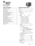
FLECK 5800 XTR2
SERVICE MANUAL
www.pentairaqua.com
TABLE OF CONTENTS
JOB SPECIFICATION SHEET
JOB SPECIFICATION SHEET..................................................... 2
INSTALLATION.......................................................................... 3
TOUCHSCREEN CONTROL QUICK START................................ 5
TOUCHSCREEN CONTROL FEATURES.................................... 7
MASTER SETTINGS PROGRAMMING....................................... 10
MASTER SETTINGS REFERENCE CHART................................ 14
MASTER RESET........................................................................ 15
CONTROL OPERATION.............................................................. 15
ALARMS AND ERRORS............................................................ 15
TROUBLESHOOTING................................................................. 16
POWERHEAD ASSEMBLY......................................................... 17
5800 CONTROL VALVE ASSEMBLY........................................... 18
TURBINE METER ASSEMBLY - P/N 60626.............................. 19
PADDLE METER ASSEMBLY - P/N 60086-50........................... 19
BYPASS VALVE ASSEMBLY (METAL)......................................... 20
BYPASS VALVE ASSEMBLY (PLASTIC)...................................... 20
2310 SAFETY BRINE VALVE...................................................... 21
WATER CONDITIONER FLOW DIAGRAMS................................ 22
DIMENSIONAL DRAWINGS....................................................... 24
INJECTOR FLOW DATA.............................................................. 25
WIRING DIAGRAM..................................................................... 26
Job Number:____________________________________________________
Model Number:__________________________________________________
Water Hardness: ________________________________________ ppm or gpg
Capacity Per Unit:________________________________________________
Mineral Tank Size:_______________ Diameter:_________ Height:__________
Salt Setting per Regeneration:______________________________________
Regenerant Flow: Downflow Upflow Backwash Downflow 2x Backwash
Filter Upflow Variable Refill Custom Downflow Custom Upflow
1. Meter Size:
A. 3/4" Paddle Wheel
Turbine
B. 1" Paddle Wheel
Turbine
C. 1-1/2" Paddle Wheel
Turbine
D. 2" Paddle Wheel
E. 3" Paddle Wheel
F. Generic_________Pulse Count__________Meter Size__________
2. System Type:
A. System #4: 1 Tank, 1 Meter, Immediate, or Delayed Regeneration
B. System #4: Time Clock
3. Cycle Settings:
A. Backwash:_____________________________________ Minutes
B. Brine and Slow Rinse:____________________________ Minutes
C. Rapid Rinse:____________________________________ Minutes
D. Brine Tank Refill:________________________________ Minutes
E. Pause Time:____________________________________ Minutes
IMPORTANT PLEASE READ:
• The information, specifications and illustrations
in this manual are based on the latest information
available at the time of printing. The manufacturer
reserves the right to make changes at any time
without notice.
• This manual is intended as a guide for service
of the valve only. System installation requires
information from a number of suppliers not known
at the time of manufacture. This product should be
installed by a plumbing professional.
• This unit is designed to be installed on potable
water system only.
• This product must be installed in compliance with
all state and municipal plumbing and electrical
codes. Permits may be required at the time of
installation.
• It is established that when daytime water pressure
exceeds 80 psi (5.5 bar), the maximum pressure
rating of 125 psi (8.6 bar) can be exceeded. A
pressure regulator must be installed on this
system or warranty is voided.
• Do not install the unit where temperatures may
drop below 32°F (0°C) or above 120°F (52°C).
• Do not place the unit in direct sunlight. Black
units will absorb radiant heat increasing internal
temperatures.
• Do not strike the valve or any of the components.
• Warranty of this product extends to manufacturing
defects. Misapplication of this product may result
in failure to properly condition water, or damage to
product.
• A prefilter should be used on installations in which
free solids are present.
• In some applications local municipalities treat
water with Chloramines. High Chloramine levels
may damage valve components.
• Correct and constant voltage must be supplied to
the controller to maintain proper function.
2 • Fleck 5800 XTR2 Service Manual
F. Second Backwash:_______________________________ Minutes
4. Drain Line Flow Control:_____________________________ gpm
5. Brine Line Flow Control:_____________________________ gpm
6. Injector Size#: _________________________________________
7. Battery Install/Change Date:_______________________________
INSTALLATION
Water Pressure
A minimum of 20 psi (1.4 bar) of water pressure is required for
the regeneration valve to operate effectively.
Electrical Facilities
An uninterrupted power supply is required. The control uses a
transformer to supply 12 VDC. Please make sure your voltage
supply is compatible with your unit before installation.
Existing Plumbing
Condition of existing plumbing should be free from lime and
iron buildup. Piping that is built up heavily with lime and/or iron
should be replaced. If piping is clogged with iron, a separate
iron filter unit should be installed ahead of the system.
Location Of System And Drain
The system should be located close to a drain to prevent air
breaks and back flow.
Outdoor Locations
When the water conditioning system is installed outdoors,
several items must be considered.
• Moisture — The system is not designed to withstand
extreme humidity or water spray from below. Examples
are: constant heavy mist, near corrosive environment,
upwards spray from sprinkler.
CAUTION This unit is for dry location use only unless used
with a Listed Class 2 power supply suitable for
outdoor use.
• Direct Sunlight — The materials used will fade or
discolor over time in direct sunlight. The integrity of the
materials will not degrade to cause system failures. If
it is necessary to locate the system in direct sunlight, a
protective outdoor cover (P/N 61882) over the valve and
controller is necessary.
• Insects — If installing in an environment that may expose
the system to insects or other small animals, a protective
cover is required. The protective outdoor cover (P/N
61882) has been designed to keep all but the smallest
insects out of the critical areas. The cover should be
installed securely in place.
4. Refer to the dimensional drawing for cutting height of the
distributor tube. If there is no dimensional drawing, cut the
distributor tube flush with the top of the tank.
5. Lubricate the distributor O-ring seal and tank O-ring
seal. Place the main control valve on tank. Note: Only use
silicone lubricant.
6. Soldering of joints near the drain port must be done prior to
connecting the Drain Line Flow Control fitting (DLFC). Leave
at least 6" (15 cm) between the DLFC and solder joints
when soldering pipes that are connected on the DLFC.
Failure to do this could cause interior damage to the DLFC.
7. Plumber tape is the only sealant to be used on the drain
fitting.
8. Make sure that the floor is clean beneath the salt storage
tank and that the tank is level.
9. Place approximately 1" (25 mm) of water above the grid
plate. If a grid is not utilized, fill to the top of the air check
(Figure 1) in the salt tank. Do not add salt to the brine tank
at this time.
CAUTION If grid plate is used, cut air check height just below
the grid plate. This is critical on 6", 7", 8" and 9"
tanks. The brine refill water must come above the
grid plate and make contact with the salt.
10.On units with a bypass, place in bypass position. Turn on
the main water supply. Open a cold soft water tap nearby
and let run a few minutes or until the plumbing is free from
foreign material (usually solder) that may have resulted
from the installation. Once clean, close the water tap.
11.Slowly place the bypass in service position and let water
flow into the mineral tank. When water flow stops, slowly
open a cold water tap nearby and let water run until the air
is purged from the unit.
12.Plug the transformer into an electrical outlet.
NOTE: All electrical connections must be connected according
to local codes. Be certain the outlet is uninterrupted.
Bypass Valves
Always provide for the installation of a bypass valve if unit is not
equipped with one.
CAUTION Water pressure is not to exceed 125 psi (8.6 bar),
water temperature is not to exceed 110°F (43°C),
and the unit cannot be subjected to freezing
conditions.
WARNING: The system must be depressurized before
removing any connections for servicing.
Installation Instructions
1. Place the media tank where you want to install the unit.
Make sure the unit is level and on a firm base.
2. During cold weather, the installer should warm the valve to
room temperature before operating.
3. All plumbing should be done in accordance with local
plumbing codes. The pipe size for a residential drain line
should be a minimum of 1/2" (13 mm). Backwash flow rates
in excess of 7 gpm (26.5 Lpm) or drain line length in excess
of 20' (6 m) require 3/4" (19 mm) drain line. Commercial
drain lines should be the same size as the drain line flow
control.
NOTE: The tank should have the distributor tube installed
and have the proper amount of regenerant in place.
60002 Rev E
Figure 1 Residential Air Check Valve
Electrical Connection
The controller operates on 12-volt DC power supply. This
requires use of the supplied power adapter included with your
system.
NOTE: The power source should be constant. Be certain the
power adapter is not on a switched outlet. Power
interruptions longer than eight hours may cause the
controller to lose the time setting. When power is
restored, the time setting must then be re-entered.
Fleck 5800 XTR2 Service Manual • 3
INSTALLATION continued
Typical Residential System Plumbing
Bath Tub Lavatory Toilet
Outside
Faucet
Hot Water
Outlet
Kitchen
Grounding
Strap
Soft Water
Hard Water
Bypass
Drain Line
Water
Heater
Laundry Tubs
Pump
or
Meter
Softener
Figure 2 Softened Water Flow
4 • Fleck 5800 XTR2 Service Manual
Brine Tank Overflow Drain (Optional)
Floor Drain
Outside
Faucet
TOUCHSCREEN CONTROL QUICK START
The 5800 XTR2 control was designed to be easy to set up
and begin using right out of the box. The following simple
procedure can be used to set up the system and begin treating
water in most typical applications.
NOTE: Steps 2 - 4 are optional and are not required to start
the system. All control settings may be changed after
the unit is in service.
1. After plugging in the unit, the Format screen (Figure 3) is
displayed.
3. After pressing
is displayed.
, the Assistance Phone screen (Figure 5)
Figure 5 Assistance Phone Screen
Enter the phone number of the water treatment
professional or company that the homeowner may call for
system service (optional). Press
when finished.
4. After pressing , the Assistance Interval screen (Figure 6)
is displayed.
Figure 3 Format Screen
Press the units button to adjust the system's units of
measure (either U.S. or metric). Press
when finished.
NOTE: If the screen is blank after plugging in the unit, touch
the screen to turn the screen on.
2. After pressing , the Assistance Name screen (Figure 4) is
displayed.
Figure 4 Assistance Name Screen
Using the keypad, type the name of the water treatment
professional or company that the homeowner may call for
system service (optional).
To enter a letter using the keypad, quickly press the keypad
button the number of times that correspond with the
position of the correct letter on the button. For example,
to enter the letter "C", quickly press the ABC button three
times. Press
when finished.
Figure 6 Assistance Interval Screen
Use the Assistance Interval screen to set the interval in
which the homeowner will need to call a water treatment
professional for system service (optional). The assistance
interval can be based on a set number of months (month
based) or a number of regenerations (regen based).
Press the interval button to select a month-based or regenbased assistance interval, then press . Press either
the month or regen button (depending on your previous
selection), and select the number of months (up to 60) or
regenerations (up to 2000) until the homeowner will need to
call for service. Press
when finished.
Fleck 5800 XTR2 Service Manual • 5
TOUCHSCREEN CONTROL QUICK START
continued
5. After pressing
, the Home screen (Figure 7) appears.
Next Scheduled
Regeneration
Day and Time
6. Start a regeneration by pressing the Regeneration button
. The Regeneration screen appears (Figure 9).
Current Cycle
Step
Regeneration
Cycle Wheel
Assistance
Diagnostics
Regeneration
Settings
Figure 7 Home Screen
The Day and Time button will be flashing, indicating that the
day of the week and time need to be set. If the date and time
are incorrect, press the Day and Time button to update to
the correct day and time. The Day and Time screen (Figure
8) appears.
12/24 Hour
Day of Week
Hour
AM/PM
Minute
Figure 8 Day and Time Screen
Press the Day of Week, Hour, Minute, and AM/PM buttons
to adjust the values to the correct day and time. Press
the 12/24 Hour button to display the time in 12 or 24 hour
format. Press the
button when finished to return to
the Home screen. Press
to return to the Home screen
without saving.
6 • Fleck 5800 XTR2 Service Manual
Figure 9 Regeneration Screen
Press the now button to begin a regeneration immediately.
7. The valve will cycle to backwash. Ensure the drain line flow
remains steady for 10 minutes or until the water runs clear.
8. Press the
button to cycle to the brine / slow rinse (Draw)
position. Ensure the unit is drawing water from the brine
tank.
9. Press the
button to cycle to the rapid rinse (Rinse)
position. Check the drain line flow, and run for five minutes
or until the water runs clear.
10.Press the
button to cycle to the brine tank fill (Refill)
cycle. Ensure water goes into the brine tank at the desired
rate. The brine valve drive cam will hold the valve in this
position to fill the brine tank for the first regeneration.
11.Put salt in the brine tank.
NOTE: Do not use granulated or rock salt.
The unit is now fully programmed and ready to treat water.
This quick setup uses the control's default settings, which are
appropriate for most residential applications.
TOUCHSCREEN CONTROL FEATURES
Features of the XTR2 Touchscreen Control
• Full-featured easy to use graphical touchscreen interface
for programming, servicing, and diagnostics.
• Non-linear programming no longer requires cycling
through every parameter when programming/servicing.
Buttons and Symbols
NOTE: Not all buttons appear on all screens.
Regeneration Cycle Wheel
Assistance
• Displays a name and phone number to call for unit
service.
Screen Navigation Arrows
• Displayed in the upper-left and upper-right corners of
the screen, these arrows allow you to navigate from one
screen to another.
Settings Arrows
• These arrows allow you to change the values of certain
settings when programming the control.
Alarm
• Displays the regeneration cycle step the system is
currently in. The wheel rotates with each step so that the
current step is shown in green.
NOTE: On metered units, the "Treatment" step on the
Regeneration Cycle Wheel will flash when water is
flowing through the unit.
Home
• Displays the Home screen.
Regeneration
• Displays the Regeneration screen, which allows you to
start a regeneration and manually cycle through the
regeneration steps.
Settings
• Displays the Settings screen, which allows you to adjust
commonly used settings. Pressing this button while in the
Settings screen provides access to the Master Settings
screen, which allows you to fully program the valve.
NOTE: Due to the complexity of these settings and the
potential for errors, Master Settings should only be
accessed by your local water professional.
Diagnostics
• Displayed when an alarm has occurred; accompanied with
an audible alarm. Press to silence the audible alarm.
Error
• Displayed when an error has occurred. Press to display
the Error screen for more detailed error information.
Advance
• This arrow allows you to advance through cycle steps
during a regeneration.
Reset
• Displayed in the Diagnostics screen to reset Totalizer
and Peak Flow data and in Master Settings to reset
parameters to default settings.
Accept
• Press to save or accept changes in control configuration.
Cancel
• Press to cancel configuration and exit to previous screen
without saving.
• Displays the Diagnostic screen, which can assist
in performing maintenance and troubleshooting
performance issues with the valve.
Fleck 5800 XTR2 Service Manual • 7
TOUCHSCREEN CONTROL FEATURES
continued
Screen Features
• Day and Time: Displays the currently programmed day of
the week and time. This button will flash if the control has
been reset.
Regeneration
Home Screen
Day and Time
Next Scheduled
Regeneration
Regenerate the system on demand by pressing the
Regeneration button on the home screen. Manual Regeneration
can only be used while the valve is in the treatment position.
From the Home screen, press the Regeneration button . The
Regeneration screen appears.
Current Cycle
Step
Return
to Home
Screen
Regeneration
Cycle Wheel
Assistance
Diagnostics
Regeneration
Settings
Figure 10 - Home Screen
The Home screen is always displayed unless the control
settings are being configured or during regeneration. This
screen displays general information about the system and
allows you to start a manual regeneration or access control
settings. Features of the screen are described below, followed
by more detailed information about each feature.
NOTE: If no button is pushed for five minutes, the screen will
enter a power save mode. The unit will continue to
operate, but the screen will be blank. Touch anywhere
on the screen to exit power save mode.
• Regeneration: Press to start a manual regeneration.
• Settings: Press to access commonly used settings.
• Diagnostics: Press to view diagnostic data.
• Assistance: Press to display the name and phone number
to call for service.
• Regeneration Cycle Wheel: Displays the cycle steps the
valve will step through during a regeneration; the current
cycle step is always at the top of the wheel.
• Treatment: The unit is treating water
• Backwash: Water flows from the bottom of the vessel
to the top of the vessel to clean the media
• Draw: Brine is drawn into the media and then slowly
rinsed out
• Rinse: Water flows from the top of the vessel to the
bottom of the vessel to rinse the media
• Refill: Brine tank is refilled with water
• Next Scheduled Regeneration: Displays the next
scheduled regeneration in either time or volume,
depending on control settings.
8 • Fleck 5800 XTR2 Service Manual
Figure 11 Regeneration Screen
• Press the now button to begin a regeneration
immediately, or press the tonight button to queue the
regeneration for the programmed regeneration time (2:00
AM by default). Pressing the tonight button again will
cancel the manual regeneration.
• During Regeneration, press the
button to immediately
advance to the next cycle step. Once in regeneration, the
volume or time will be displayed below the
button.
Day and Time
From the Home screen (displayed in Figure 10 above) press the
Day and Time button. The Day and Time screen appears.
12/24 Hour
Day of Week
Hour
AM/PM
Minute
Figure 12 Day and Time Screen
• Press the Day of Week, Hour, Minute, and AM/PM buttons
to adjust the values to the correct day and time. Press
the 12/24 Hour button to display the time in 12 or 24 hour
format. Press the
button when finished to return to the
Home screen.
TOUCHSCREEN CONTROL FEATURES
continued
Settings
The Settings screen allows you to change basic control settings
including time of regeneration and water hardness. These
settings improve the operational efficiency of the system and
can be adjusted independently from other control settings
without needing to enter Master Settings.
From the Home screen, press the Settings button
Settings screen is displayed.
User Assistance
The Assistance screen displays the name and phone number
that the homeowner may call for service of the unit. Press the
Assistance button
from the Master Settings or Home
screens. The Assistance screen is displayed.
. The
Figure 14 Assistance Screen
• This information is entered upon initial control startup
(see TOUCHSCREEN CONTROL QUICK START) or can be
changed in Master Settings.
Master Settings
Figure 13 Settings Screen
• Press regen time to adjust the time of day that an
automatic regeneration cycle will begin.
• Press hardness to adjust the hardness setting. This value
should match the hardness of the incoming untreated
water supply.
• Press
to save your changes or press
to return to
the Home screen.
Additional features may be accessed from the Settings screen
by pressing the Settings button at the bottom of the screen (see
Figure 13):
• Master Settings: Displays the Master Settings screen,
which allows you to fully program the valve.
NOTE: Due to the complexity of these settings and the
potential for errors, Master Settings should only be
accessed by your local water professional.
• Press the Home button to return to the Home screen.
NOTE: The Assistance screen is also displayed automatically
when the system reaches the programmed assistance
interval. See TOUCHSCREEN CONTROL QUICK START.
Master Settings
The Master Settings screen includes all configurable
parameters available in the control.
CAUTION Improperly adjusting master settings may cause
the system to operate incorrectly. Before entering
master settings please contact your professional
water dealer.
From the Settings screen, press the Settings button .
A warning message appears.
NOTE: Settings can not be accessed during a regeneration.
If a regeneration starts while in the settings menu,
the screen will return to the main screen and all
parameters will be voided.
Figure 15 Master Settings Warning Screen
• Press
to continue to the Password screen or press
to return to the Home screen.
Fleck 5800 XTR2 Service Manual • 9
TOUCHSCREEN CONTROL FEATURES
continued
MASTER SETTINGS PROGRAMMING
CAUTION Improperly adjusting master settings may cause
the system to operate incorrectly. Before entering
master settings please contact your professional
water dealer.
The following is a detailed overview of settings available in the
Master Settings screen. Please see the MASTER SETTINGS
REFERENCE CHART for the complete set of values and ranges
available to program while in Master Settings.
The Password screen displays a numeric keypad.
Format Screen
From the main Master Settings screen (Figure 18) press the
format button to display the Format screen.
Screen
Navigation
Arrow
Figure 16 Password Screen
• Enter the master settings password 1201 and press
to continue to the Master Settings screen, or press
return to the Home screen.
After entering the correct password and pressing
Master Settings screen is displayed.
to
, the
Figure 18 Format Screen
• language: Displays the language used on the control
(currently English only).
• units: Contains settings for the unit type (either US or
Metric) to be used in the control.
• Press the screen navigation arrows at the upper-right
and left of the screen to navigate to the Assistance Name,
Assistance Phone, and Assistance Interval screens.
See TOUCHSCREEN CONTROL QUICK START for more
information about these settings.
• Press
to save changes.
Valve Screen
Figure 17 Master Settings Screen
From the main Master Settings screen (Figure 18) press the
valve button to display the Valve screen.
While in the Master Settings screen, press
to save all
set parameters to a custom profile (see "NON-FACTORY
SETTINGS" on page 12) or press the Home button to
return to the Home screen.
Features of the Master Settings screen are described below.
See MASTER SETTINGS PROGRAMMING and MASTER
SETTINGS REFERENCE CHART for more detailed information.
• format: Contains settings for Language, Units, Assistance
Name, Assistance Phone, and Assistance Interval.
See TOUCHSCREEN CONTROL QUICK START for more
information about these settings.
• valve: Contains settings for System, Valve, and
Regeneration Type.
• regen: Contains settings for Regen Flow.
• relay: Contains settings for Aux 1 and Aux 2 relays.
• meter: Contains settings for Meter Types.
• remote regen: Contains settings for triggering a
regeneration via a remote input.
10 • Fleck 5800 XTR2 Service Manual
Figure 19 Valve Screen
MASTER SETTINGS PROGRAMMING
continued
• system: Displays the system type. Type 4 (single system)
is currently the only available selection.
• valve: Displays the valve model. 5800XTR2 is currently the
only available selection.
• regen type: Contains settings for the type of regeneration
to use for the system. Regeneration types are described
in detail below.
Regeneration Types
The XTR2 control supports five different Regeneration Types.
The Regeneration Type defines the method of automatic
regeneration for the system. Each type is explained below.
Time Clock
Triggers a regeneration on a timed interval. The control will
initiate a regeneration cycle at the selected Regeneration Time
when the number of days since the last regeneration equals
the Day Override value. The Day Override can be set from 1 - 99
days as well as partial day intervals of 4, 8, 12, 16 and 20 hours.
Meter Immediate
Measures water usage and regenerates the system as soon
as the calculated system capacity is depleted. The control
calculates the system capacity by dividing the unit capacity by
the feed water hardness. Meter Immediate systems do not use
a reserve volume. The control will also start a regeneration
cycle at the programmed regeneration time if a number of days
equal to the Day Override pass before water usage depletes
the calculated system capacity. The Day Override parameter
default is OFF, and REGEN TIME will be grayed out unless the
day override value has been modified.
CAUTION When setting the system for meter immediate
regeneration, setting the capacity to a value lower
than that of feed water hardness may cause the
system to constantly regenerate. If this occurs,
disconnect the motor from the control and correct
the capacity and feed water hardness values in
Master Settings. See "TROUBLESHOOTING" on page
16 for more information.
Meter Delayed
Measures water usage and regenerates the system at the
selected Regeneration Time after the calculated system
capacity is depleted. The control calculates the system capacity
by dividing the unit capacity by the feed water hardness and
subtracting the reserve.
The reserve should be set to ensure that the system delivers
treated water between the time the system capacity is depleted
and the actual regeneration time. Reserves can be set at a
Fixed Volume, Fixed Percentage of capacity, a Variable Reserve
based on the previous calendar day's water usage, or a Weekly
Reserve based on the average water usage for the current day
of the week. The default for the day override parameter is OFF,
and the default reserve type is Weekly Reserve.
A Meter Delayed control will also start a regeneration cycle
at the selected Regeneration Time if a number of days equal
to the Day Override pass before water usage depletes the
calculated system capacity.
If the regen type is changed from Meter Immediate to a Meter
Delayed (or vice-versa), all parameters within those types must
be reset to factory default.
Volume Override Immediate
Regenerates the system immediately after the selected Volume
Override value is depleted. A Volume Override Immediate
control will also start a regeneration cycle at the selected
Regeneration Time if a number of days equal to the Day
Override pass before water usage depletes the calculated
system capacity.
Volume Override Delayed
Regenerates the system at the selected Regeneration Time
after the selected Volume Override value is depleted. A Volume
Override Delayed control will also start a regeneration cycle
at the selected Regeneration Time if a number of days equal
to the Day Override pass before water usage depletes the
calculated system capacity.
NOTE: Volume Override Immediate and Volume Override
Delayed are only available if Regenerant Flow is set to
"Filter" or "Upflow Filter".
Regeneration Screen
From the main Master Settings screen (Figure 18) press the
regen button to display the Regeneration screen.
Figure 20 Regeneration Screen
Adjusting
Regeneration settings will turn any set
CAUTION
relays off. Any required relays will need to be
reprogrammed in the Relay Output screen.
• regen flow: Contains settings for the type of regenerant
flow to be used in the valve. Changes to this setting
affects the cycle steps displayed in the Regeneration
Cycle Wheel on the Home screen. Regenerant flow cycle
steps are described below. See TOUCHSCREEN CONTROL
FEATURES for cycle step definitions.
• upflow: Cycle steps are as follows: Draw, Backwash,
Rinse, Refill
• downflow: Cycle steps are as follows: Backwash, Draw,
Rinse, Refill
• downflow 2X backwash: Cycle steps are as follows:
Backwash, Draw, Backwash, Rinse, Refill
• filter / upflow filter : Cycle steps are as follows:
Backwash, Rinse
• custom upflow / downflow: Allows for up to 20
programmable cycle steps.
• variable refill: Cycle steps are as follows: Refill, Pause,
Draw, Backwash, Rinse
• aio: Cycle steps are as follows: Backwash, Air Draw,
Rinse
Fleck 5800 XTR2 Service Manual • 11
MASTER SETTINGS PROGRAMMING
continued
Relay Output Screen
Remote Regen Screen
From the main Master Settings screen (Figure 18) press the
remote regen button to display the Remote Regen screen.
From the main Master Settings screen (Figure 18) press the
relay button to display the Relay Outputs screen.
Figure 21 Relay Outputs Screen
• auxiliary 1 / auxiliary 2: Contains settings for
programming up to two auxiliary relay outputs. There are
three types of relays that can be programmed:
• Cycle Based: The relay will turn on when the valve
moves to the specified regeneration cycle steps. To
program, select each cycle step button for which the
relay should turn on.
• Time Based: The relay will turn on and off at up to two
specified start and end times.
• Volume Based: The relay will turn on when the valve
has treated a specified volume of water. Duration can
be set for up to two hours.
Meter Screen
From the main Master Settings screen (Figure 18) press the
meter button to display the Meter screen.
Figure 22 Meter Screen
• meter type: Contains settings for the type of meter
installed with the system.
• generic: A generic option is available if the installed
meter does not match any other selection. Requires
setting the number of pulses per volume to ensure proper
metering.
12 • Fleck 5800 XTR2 Service Manual
Figure 23 Remote Regen Screen
• remote regen: Contains settings for triggering a
regeneration via a remote input. Select a value in seconds
that the remote switch must be closed in order to trigger
the regeneration.
Connect a remote switch (such as a differential pressure
switch) to the P4 remote input terminals on the back of the
XTR2 control board. See "WIRING DIAGRAM" on page 26.
When the remote switch is closed for the number of seconds
specified in the Remote Regen screen, a regeneration will be
triggered regardless of volume, capacity, or time remaining
until the next scheduled regeneration.
Non-Factory Settings
After all parameters in Master Programming have been set,
these settings can be saved to a custom profile by pressing
on the main Master Settings screen (see Figure 18 Master
Settings Screen). After pressing , the Non-Factory Settings
screen appears.
Figure 24 Non-Factory Settings Screen
Press
to save all programmed Master Settings parameters
to non-factory settings. At any point, the control can be reset
to these saved custom settings (see "MASTER RESET" on
page 15). By performing a custom reset, any setting that
is subsequently programmed without saving to non-factory
settings will be reset to the previously saved non-factory
settings in the control.
MASTER SETTINGS PROGRAMMING
continued
Diagnostics
The control records and displays a variety of diagnostic data to
assist with troubleshooting performance issues and fine-tuning
system efficiency. Press the Diagnostics button
from the
Master Settings or Home screens to view the Diagnostic
screen.
NOTE: Only Peak Flow and Totalizer can be programmed they can be reset to zero. The Totalizer value should
be updated every time the diagnostic screen is
entered.
NOTE: Totalizer has a maximum value of 999,999,999. If this
number is reached, the Totalizer must be reset to zero
to continue tracking this value.
Figure 25 Diagnostic Screen
• Press the screen navigation arrows at the upper-right and
left of the screen to view each diagnostic parameter.
• Press the Home button to return to the Home screen.
NOTE: If a regeneration occurs while in the Diagnostic screen,
the unit will return to the main screen.
Parameter
Description
Flow Rate
Displays the current flow rate.
Peak Flow
Displays maximum flow rate of water since
last reset.
Totalizer
Displays total volume of water used since
last reset.
Last Regen
Displays when last regeneration occurred.
Reserve
Displays the reserve volume based on the
reserve type selected under master settings.
*This parameter is only available for meter
delayed regeneration type.
Software Ver
Displays the software version installed on
the controller.
No of Regens
Displays how many manually and system
initiated regenerations the system has gone
through since last reset.
Regen Interval
Displays the average length of time between
regenerations based on the past four
regenerations.
Daily Usage
Displays average water usage for each day
of the week based on the usage for the past
four weeks.
Usage Since Regen
Displays water usage since last regeneration.
Last Change
Displays the date and time of the last update
to Master Settings.
Fleck 5800 XTR2 Service Manual • 13
MASTER SETTINGS REFERENCE CHART
CAUTION Before entering Master Settings, please contact your local professional water dealer.
Master Settings Options
Screen Name
Parameters
Values
Format
Language
English
English is currently the only available selection.
Units
U.S.
Metric
Changes system units and values across all parameters in the control. All
programmed units and values should be recalculated after adjusting this setting.
Assistance
Name
Free-form text
A - Z and space
Name of service provider to display when viewing the Assistance screen.
20 character limit
Assistance
Phone
Free-form text
0 - 9 and space
Phone number of service provider to display when viewing the Assistance screen.
20 character limit
Assistance
Interval
Month Based
Regen Based
1 - 60
1 - 2000
Off
Valve
System
4
Valve
5800
Regen. Type
Time Clock
Meter Immediate
Meter Delayed
Volume Immediate
Volume Delayed
Capacity
1 - 99 999 999
grains / grams
Only required on metered systems to calculate treated water capacity and reserve.
Represents total system capacity between regenerations.
Hardness
1 - 199 grains/gallon
1 - 1 999 mg/liter
Only required on metered systems to calculate treated water capacity and reserve.
Represents hardness of untreated water.
Reserve
Fixed %
Fixed Volume
Weekly Reserve
Variable Reserve
Day Override
1 - 99 days
4, 8, 12, 16, 20 hours
Regen Time
12 / 24 hour clock
Volume Override
1 - 99 999 999
gallons / liters
Only displayed when Regeneration Type is Volume Immediate or Volume Delayed.
Regeneration
Regen. Flow
Upflow
Downflow
Downflow 2x Backwash
Filter
Upflow Filter
Custom Upflow
Custom Downflow
Variable Refill
AIO
Cycle steps on the Home screen and during regeneration will change to reflect the
cycle steps and order in the selected Regenerant Flow.
Additional Regeneration screen parameters are dependent upon selected
Regenerant Flow. Not all parameters will be displayed.
Custom Upflow and Downflow allows for up to 20 programmable cycle steps.
Variable Refill calculates refill time based on Salt Dosage, Media Volume, and
BLFC Size.
Time per cycle step can be programmed for all other Regenerant Flow options.
Relay Outputs
Aux 1/Aux 2
Cycle Based
Time Based
Volume Based
Off
For Cycle Based relays, select the cycle steps on which the relays will turn on.
For Time Based relays, two start/end times will need to be selected for each relay.
Relay times are based on total regeneration cycle time.
Volume Based relays can be programmed from zero gallons/liters to the full
system capacity. Duration can be set from zero seconds to two hours. Volume
Based option is not available when Regeneration Type is set to Time Clock.
Meter
Meter Type
.75 inch Paddle
.75 inch Turbine
1.00 inch Paddle
1.00 inch Turbine
1.50 inch Paddle
1.50 inch Turbine
2.00 inch Paddle
3.00 inch Paddle
Generic
Generic
1 - 999.9 /1 - 1500
pulses per gallon / liter
Remote Regen
1 - 255 seconds
Off
Remote Regen
Notes
Set to automatically display the Assistance screen after a certain number of
months or regenerations.
System 4 (single system) is currently the only available selection.
5800 is the only available selection.
Regeneration Types are described in detail on page 11.
Additional Valve screen parameters are dependent upon selected Regeneration
Type. Not all parameters will be displayed.
Meter Delayed regeneration type has four reserve options (Fixed %, Fixed
Volume, Variable Reserve, Weekly Reserve). The control will display additional
configuration options depending on the selected reserve type.
Only available when Meter Delayed regeneration type is selected.
Selecting Fixed % or Fixed Volume will display additional configuration options.
Weekly Reserve is calculated based on average day of week's water usage.
Variable Reserve is calculated based on previous day's water usage.
Available to be programmed for all Regeneration Types.
Required for Time Clock and delayed Regeneration Types. Set for immediate
regeneration types only when a Day Override is also set.
Select the type of meter installed with the system. A Generic option is available
if the installed meter does not match any other selection. Selecting the Generic
meter type requires setting the number of pulses per gallon or liter to ensure
proper metering.
Only available when Generic meter type is selected.
Select a value in seconds that the remote switch must be closed in order to trigger
the regeneration.
NOTE: Some items may not be shown depending on control configuration. The control will discard any changes and exit Master
Settings if any button is not pressed for five minutes.
14 • Fleck 5800 XTR2 Service Manual
MASTER RESET
Press the
button while in the Master Settings main screen
(Figure 18) to display the Reset screen.
CAUTION If power fails during a regeneration cycle, the
valve will remain in its current position until power
is restored. The valve system should include all
required safety components to prevent overflows
resulting from a power failure during regeneration.
The control will not start a new regeneration cycle without
power. If the valve misses a scheduled regeneration due to
a power failure, it will queue a regeneration. Once power is
restored, the control will initiate a regeneration cycle the next
time that the Time of Day equals the programmed regeneration
time. Typically, this means that the valve will regenerate one
day after it was originally scheduled. If the treated water
output is important and power interruptions are expected, the
system should be set up with a sufficient reserve capacity to
compensate for regeneration delays.
Remote Lockout
Figure 26 Reset Screen
Press the factory button to reset all control parameters to
their factory defaults, or press the non-factory button to reset
control parameters to previously saved custom settings (see
"NON-FACTORY SETTINGS" on page 12). A warning screen
appears before parameters are reset. Press
to confirm the
reset or press
to return to Master Settings.
CONTROL OPERATION
If a remote switch is installed, the control will not allow the
system to go into regeneration until the regeneration lockout
input signal to the control is cleared. This requires a contact
closure to clear the lockout condition. The recommended
gauge wire is 20 with a maximum length of 500 feet. See
"WIRING DIAGRAM" on page 26.
ALARMS AND ERRORS
If an error in valve or control function occurs, an alarm will
sound and the Home screen will display the Error
Alert button
and the Alarm button
.
Control Operation During Regeneration
During regeneration, the Regeneration Cycle Wheel shows the
regeneration step the valve is advancing to, or has reached, and
the time remaining in that step. Once all regeneration steps are
complete the valve returns to treatment position and resumes
normal operation. The time remaining in regeneration will be
displayed on the home screen in hours and minutes.
Pressing the
button during a regeneration cycle
immediately advances the valve to the next cycle step position
and resumes normal step timing. The
button is only shown
when the valve is in position and the motor has stopped.
Control Operation During Programming
The control can only be programmed with the valve in
treatment. While being programmed the control continues
to operate normally, monitoring water usage and keeping all
displays up to date. Control programming is stored in memory
permanently until reset.
Control Operation During a Power Failure
The XTR2 includes internal power backup. In the event of
power failure, the control shifts into a power-saving mode. The
control stops monitoring water usage. The display and motor
shut down, but it continues to keep track of the time and day
for a minimum of eight hours.
The system configuration settings are stored in a non-volatile
memory and are stored indefinitely with or without power.
The Time of Day button flashes when there has been a power
failure. Press the button to stop the Time of Day from flashing.
If power fails while the unit is in regeneration, the control will
save the current valve position before it shuts down. When
power is restored, the control will resume the regeneration
cycle from the point where power failed.
Error Alert
Alarm
Figure 27 Alarm and Error Alert
• Press the Alarm button to mute the alarm.
• Press the Error Alert button to view information about
the error.
If the display is in sleep mode when an error occurs, the screen
will turn on for five minutes. The error will beep for one second
per minute until the error is cleared. If the error is not cleared
after five minutes, the screen will switch to power saving mode
and display the Error Alert button as a screen saver.
See TROUBLESHOOTING for more information about error
conditions.
Fleck 5800 XTR2 Service Manual • 15
TROUBLESHOOTING
Problem
Cause
Valve constantly
regenerates
Error in programming has caused
a regeneration loop condition in the
control.
Correction
Disconnect the motor from the control circuit board (see "WIRING DIAGRAM" on
page 26 for location on circuit board). A Motor Stall error will occur, allowing
access to Master Settings. Navigate to the Valve screen and check Regen Type
settings. Ensure that the value for Capacity is larger than the value for Hardness,
and save settings.
If the error continues to occur, unplug the unit, put it into bypass and contact
technical support.
Time of day not
maintained after
power outage
Battery dead
Replace with new CR 2032 3V coin cell battery (see "WIRING DIAGRAM" on page
26).
Error Alerts
NOTE: An Error Alert appears on the Home screen if an error
condition is detected. Press the Error Alert button
to view the error message.
Error Screen
Display
Cause
Reset and Recovery
Motor Stall
No state changes in the optical
sensor are detected for six
seconds.
Unplug the unit and plug back in. Allow the control to attempt to find position again.
No changes
detected in the
optical sensor for 6
seconds
Verify the optical sensor is in place with the wires connected to the circuit board.
Verify the motor and drive train components are in good condition and assembled
properly. Check the valve and verify that the piston travels freely. Replace/
reassemble the various components as necessary.
Plug the unit back in and observe its behavior. If the error reoccurs, unplug the unit,
put it into bypass and contact technical support.
Motor Run-On
Undesired change
detected in the
optical sensor
Regeneration
No regeneration for
more than 30 days
An undesired optical sensor state
change occurred.
The system has not regenerated for
more than 30 days.
Non-critical error. Extra optical sensor pulse detected. Press the Regeneration
button to advance motor to clear error.
Perform a Manual Regeneration to reset the error.
If the system is metered, verify that it is measuring flow by running service water
and watching for the flow indicator on the display. If the unit does not measure flow,
verify that the meter cable is connected properly and that the meter is functioning
properly.
Enter Master Settings and verify that the unit is configured properly for the valve
configuration. Check that the correct system capacity has been selected, that the
day override is set properly, and that meter is identified correctly. Correct the setting
as necessary.
Valve Position
Valve took over a
minute to find cycle
step
Reset Error
Probable
Mechanical Failure
Valve has failed to find position in
one minute.
Unplug the unit and plug it back in. If error continues, call technical support.
The valve has reset at least five
times in a short amount of time.
Attempt to perform a manual regeneration. If error continues, call technical
support.
16 • Fleck 5800 XTR2 Service Manual
POWERHEAD ASSEMBLY
1
6
4
2
7
BR61501-5800 Rev A
3
BR43414 Rev A
Item No.
QTY
Part No.
Description
1����������������1�������� 61832-00������������Cover Assembly, Black/Blue
��������������������������� 61832-01������������Cover Assembly, Black/Black
��������������������������� 61832-02������������Cover Assembly, Black/Silver
5
2����������������1�������� 61836�����������������Panel Gear Assembly, Downflow/
Upflow
3����������������1�������� 61931-01������������Timer Assy, XTR2 Touch, w/ Logo
��������������������������� 61931-02������������Timer Assy, XTR2 Touch, w/o
Logo
4����������������1�������� 61835�����������������Motor Assembly
5����������������1�������� 61882�����������������Cover Assembly, Environmental
6����������������1�������� 43291�����������������Transformer 12V UL
7����������������1�������� 43318�����������������Transformer, Intl, 12V UL
BR61882 Rev B
Fleck 5800 XTR2 Service Manual • 17
5800 CONTROL VALVE ASSEMBLY
8
13
14
16
18
7
3
15
6
17
2
4
5
12
1
19
10
9
Item No.
QTY
Part No.
Description
11
BR61500-5800 Rev A
���������� 60705-12��������������� DLFC, Plastic, 1.2 gpm
���������� 60705-13��������������� DLFC, Plastic, 1.3 gpm
���������� 60705-15��������������� DLFC, Plastic, 1.5 gpm
���������� 60705-17��������������� DLFC, Plastic, 1.7 gpm
���������� 60705-20��������������� DLFC, Plastic, 2.0 gpm
���������� 60705-24��������������� DLFC, Plastic, 2.4 gpm
���������� 60705-30��������������� DLFC, Plastic, 3.0 gpm
���������� 60705-35��������������� DLFC, Plastic, 3.5 gpm
���������� 60705-40��������������� DLFC, Plastic, 4.0 gpm
���������� 60705-45��������������� DLFC, Plastic, 4.5 gpm
5������������������� 2��������� 18262�������������������� Screw, Hex Washer Head, #10-24 x
1.00
���������� 60705-50��������������� DLFC, Plastic, 5.0 gpm
6������������������� 1��������� 19654�������������������� Label, 0.125 gpm Brine Flow
���������� 60705-60��������������� DLFC, Plastic, 6.0 gpm
���������� 60705-20��������������� DLFC, Plastic, 2.0 gpm
���������� 60705-70��������������� DLFC, Plastic, 7.0 gpm
���������� 60706-8.0�������������� DLFC, AC x 3/4"F, 8 gpm
���������� 60706-9.0�������������� DLFC, AC x 3/4"F, 9 gpm
���������� 60706-10��������������� DLFC, AC x 3/4"F, 10 gpm
���������� 60706-12��������������� DLFC, AC x 3/4"F, 12 gpm
���������� 60706-15��������������� DLFC, AC x 3/4"F, 15 gpm
1������������������� 1��������� 61857-01��������������� Valve Body Assy, Downflow/Upflow
(Includes Items 9, 10, 11, 12)
�������������������������������� 61857-20��������������� Valve Body Assy, Mixing, Downflow/
Upflow (Includes Items 9, 10, 11, 12)
2������������������� 1��������� 18271�������������������� Screen Injector, 5000
3������������������� 1��������� 40064�������������������� Seal Injector
4������������������� 1��������� 18277�������������������� Cap Injector
���������� 18278-20��������������� Injector Cap Assy, 1610 Regulated,
5000, 20 psi, Black, Upflow
���������� 18278-30��������������� Injector Cap Assy, 1610 Regulated,
5000, 30 psi, Black, Upflow
���������� 12128�������������������� Label, 0.25 gpm BLFC
���������� 10759�������������������� Label, 0.5 gpm 1.5 lbs Salt/Min
���������� 10760�������������������� Label, 1.0 gpm 3 lbs Salt/Min
7������������������� 1��������� 13333�������������������� Label, Injector, Blank
8������������������� 3��������� 18261�������������������� Screw, Hex Washer Head, #10-24 0.81
9������������������� 1��������� 13304�������������������� O-ring, -121
10����������������� 1��������� 18303-01��������������� O-ring, -336, 560CD
11����������������� 1��������� 13030�������������������� Retainer, Distributor Tube O-ring
12����������������� 1��������� 18312�������������������� DLFC Housing Retainer Clip
13���������������������������� 61837�������������������� Piston and Seal Kit Assy, Downflow,
5800
���������� 61838�������������������� Piston and Seal Kit Assy, Upflow, 5800
14����������������� 1��������� 60032�������������������� Brine Valve, 4600/5600
15����������������� 1��������� 13302�������������������� O-ring, -014
16���������������������������� 60022-12��������������� BLFC, 0.125 gpm
���������� 60022-25��������������� BLFC, 0.25 gpm
���������� 60022-50��������������� BLFC, 0.5 gpm
���������� 60022-100������������� BLFC, 1.0 gpm
17���������������������������� 60705-00��������������� DLFC, Plastic, Blank
���������� 60705-06��������������� DLFC, Plastic, 0.60 gpm
���������� 60705-08��������������� DLFC, Plastic, 0.80 gpm
���������� 60705-10��������������� DLFC, Plastic, 1.0 gpm
18 • Fleck 5800 XTR2 Service Manual
18���������������������������� 18272-000������������� Injector Assy, 1610, #000, Brown
���������� 18272-00��������������� Injector Assy, 1610, #00, Violet
���������� 18272-0����������������� Injector Assy, 1610, #0, Red
���������� 18272-1����������������� Injector Assy, 1610, #1, White
���������� 18272-2����������������� Injector Assy, 1610, #2, Blue
���������� 18272-3����������������� Injector Assy, 1610, #3, Yellow
19���������������������������� 18276-01��������������� Injector Assy, Plug, w/O-rings
Not Shown:
���������� 40947-01��������������� Plug, Brine Valve, w/O-ring, 560CD
���������� 13918-01��������������� BLFC Module Plug Assy, w/O-ring
NOTE: In upflow units, the Injector Plug and Injector Assy are put in the
reverse holes. In filter units, both injector holes are plugged with
18276-01.
CAUTION
Excessive side load on piston rod may cause premature
damage. If seal/spacer stack is stuck in valve bore during
disassembly, rotate stack prior to removal.
TURBINE METER ASSEMBLY - P/N 60626
PADDLE METER ASSEMBLY P/N 60086-50
1
2
4
5
3
8
Item No.
QTY
Part No.
Description
1����������������1�������� 19797�����������������Meter Assy, 3/4" Dual Port, SLP
1
2
BR60626
3
9
7
2����������������2�������� 19569�����������������Clip, Flow Meter
3����������������2�������� 13314�����������������Screw, Slot Ind Hex, 8-18 x 0.60
Not Shown:
�������� 14613�����������������Flow Straightener
�������� 19791-01������������Meter Cable Assy, Turbine/SXT
10
11
6
BR60086 Rev E
Item No.
QTY
Part No.
Description
1����������������1�������� 14716�����������������Meter Cap Assy, NT (includes
items 2, 3, and 4)
2����������������1�������� 13874�����������������Cap, Meter, Electronic
3����������������1�������� 13847�����������������O-ring, -137, Std, Meter
4����������������1�������� 17798�����������������Screw, Slot Hex Washer Head
5����������������1�������� 19121-01������������Meter Cable Assy, SXT, Paddle
(not included in P/N 60086-50)
6����������������1�������� 13821�����������������Body, Meter, 5600
7����������������1�������� 13509�����������������Impeller, Meter
8����������������4�������� 12473�����������������Screw, Hex Wsh, 10-24 x 5/8
9����������������4�������� 13255�����������������Clip, Mounting
10���������������4�������� 13314�����������������Screw, Slot Ind Hex, 8-18 x 0.60
11���������������4�������� 13305�����������������O-ring, -119
12���������������1�������� 14613�����������������Flow Straightener
Fleck 5800 XTR2 Service Manual • 19
BYPASS VALVE ASSEMBLY (METAL)
BYPASS VALVE ASSEMBLY (PLASTIC)
6
9
8
6
5
4
3
3
1
2
BR60049 Rev H
4
2
10
BR18706 Rev J
5
BR41027 Rev G
1
Item No.
QTY
Part No.
Description
1����������������2�������� 13305�����������������O-ring, -119
2����������������2�������� 13255�����������������Clip, Mounting
3����������������2�������� 13314�����������������Screw, Slot Ind Hex, 8-18 x 0.60
7
4����������������1�������� 18706�����������������Yoke, 1", NPT, Plastic
�������� 18706-02������������Yoke, 3/4", NPT, Plastic
5����������������1�������� 13708-40������������Yoke, 1", Sweat
6
60040SS Rev Y
60041SS Rev AA
Item No.
QTY
Part No.
Description
1����������������1�������� 40614�����������������Bypass Body, 3/4"
�������� 40634�����������������Bypass Body, 1", SS
2����������������1�������� 14105�����������������Seal, Bypass, 560CD
3����������������1�������� 11972�����������������Plug, Bypass
4����������������1�������� 11978�����������������Side Cover
5����������������1�������� 13604-01������������Label
6����������������8�������� 15727�����������������Screw, 10-24 x 0.5"
7����������������1�������� 11986�����������������Side Cover
8����������������1�������� 11979�����������������Lever, Bypass
9����������������1�������� 11989�����������������Screw, Hex Head, 1/4-14 x 1.5"
10���������������1�������� 60040SS�������������Bypass Valve, 5600, 3/4" NPT
Black Grip Lever, SS
�������� 60041SS�������������Bypass Valve, 5600, 1" NPT Black
Grip Lever, Stainless Steel
Not Shown:
2�������� 19228-01������������Adapter Assy, Coupling,
w/O-rings
20 • Fleck 5800 XTR2 Service Manual
�������� 13708-45������������Yoke, 3/4", Sweat
�������� 19275�����������������Yoke, Angle 90 Deg, 3/4", NPT
�������� 19275-45������������Yoke, Angle 90 Deg, 3/4", Sweat
�������� 19620-01������������Yoke, Assy, 3/4", R/Angle 90 Deg,
w/O-rings, Clips & Screws
�������� 40636�����������������Yoke, 1-1/4", NPT
�������� 40636-49������������Yoke, 1-1/4", Sweat
�������� 41027-01������������Yoke, 3/4", NPT, Cast, Machined
�������� 41026-01������������Yoke, 1", NPT, Cast, Machined,
SS
�������� 41026-02������������Yoke, 1", BSP, Cast, Machined, SS
�������� 18706-10������������Yoke, 1", BSP, Plastic
�������� 41027-02������������Yoke, 3/4", BSP, Cast, Machined
�������� 18706-12������������Yoke, 3/4", BSP, Plastic
�������� 19620-01������������Yoke Assy, 3/4", R/Angle, 90 Deg
6����������������1�������� 60049�����������������Bypass Plastic
Not Shown:
2�������� 19228-01������������Adapter Assy, Coupling,
w/O-rings
2310 SAFETY BRINE VALVE
11
11
8
7
9
6
13
12
5
1
10
2
4
9
3
14
42112 Rev A
Item No.
QTY
Part No.
Description
1����������������1�������� 19645�����������������Body, Safety Brine Valve, 2310
2����������������1�������� 19803�����������������Safety Brine Valve Assy
3����������������1�������� 19804�����������������Screw, Sckt Hd, Set, 10-24 x 0.75
4����������������1�������� 19805�����������������Nut, Hex, 10-24, Nylon Black
5����������������1�������� 19652-01������������Poppet Assy, SBV w/O-ring
6����������������1�������� 19649�����������������Flow Dispenser
7����������������1�������� 11183�����������������O-ring, -017
8����������������1�������� 19647�����������������Elbow, Safety Brine Valve
9����������������2�������� 19625�����������������Nut Assy, 3/8" Plastic
10���������������1�������� 18312�����������������Retainer, Drain
11���������������1�������� 60014�����������������Safety Brine Valve Assy, 2310
12���������������2�������� 10150�����������������Grommet, 0.30 Dia
13���������������1�������� 60068-10.5���������Float Assy, 2310, w/10.5" Rod
�������� 60068-11.5���������Float Assy, 2310, w/11.5" Rod
�������� 60068-20������������Float Assy, 2310, w/20" Rod
�������� 60068-30������������Float Assy, 2310, w/30" Rod
14���������������1�������� 60002-11.38�������Air Check, #500, 11.38" Long
�������� 60002-27������������Air Check, #500, 27" Long
�������� 60002-32������������Air Check, #500, 32" Long
�������� 60002-34������������Air Check, #500, 34" Long
�������� 60002-36������������Air Check, #500, 36" Long
�������� 60002-48������������Air Check, #500, 48" Long
�������� 60002-26.25�������Air Check, #500, 26.25" Long
�������� 60002-33.25�������Air Check, #500, 33.25" Long
Fleck 5800 XTR2 Service Manual • 21
WATER CONDITIONER FLOW DIAGRAMS
Downflow
1. Service Position (Treatment)
4. Rapid Rinse Position (Rinse)
2. Backwash Position
5. Brine Tank Refill Position (Refill)
3. Brine/Slow Rinse Position (Draw)
22 • Fleck 5800 XTR2 Service Manual
WATER CONDITIONER FLOW DIAGRAMS
continued
Upflow
1. Service Position (Treatment)
4. Rapid Rinse Position (Rinse)
2. Brine/Slow Rinse Position (Draw)
5. Brine Tank Refill Position (Refill)
3. Backwash Position
Fleck 5800 XTR2 Service Manual • 23
12.7
.50
53.8
2.12
111.3
4.38
73.7
2.90
21.5
.85
38.7
1.53
70.2
2.77
232.3
9.15
DIMENSIONAL DRAWINGS
91.4
3.60
182.9
7.20
24 • Fleck 5800 XTR2 Service Manual
7.6
.30
BR61500-5800LNE Rev A
INJECTOR FLOW DATA
TR18755 Rev B
Fleck 5800 XTR2 Service Manual • 25
WIRING DIAGRAM
5800 XTR2 Rev0.8
BATTERY
CR 2032 3V
OPTIONAL
INTERLOCK
SWITCH (N.O.)
CLOSED
CONTACT
PREVENTS
REGENERATION
P9 PRODUCTION
TEST PORT
OPTIONAL
REMOTE
SIGNAL
START
SWITCH
(N.O.)
5
4
CLOSED
CONTACT
INITIATES
REGENERATION
IF ENABLED
MOTOR
2
1 GND
2 START
3 LOCK
1
LOCK
P4 REMOTE
START
FLOW
1 NC
2 NO
3 COMMON
A1 AUX 1
3 COMMON
MOTOR
3
SIGNAL
2
- GND
1
+ 12V
- GND
POWER
+ 12V
5A / 250V Max
P10
1 NC
2 NO
PHOTO INTERRUPTER
3
A2 AUX 2
USB
(FUTURE USE)
TOUCH SCREEN
BR43415U Rev A
26 • Fleck 5800 XTR2 Service Manual
For Fleck Product Warranties visit:
Fleck para las garantías de los productos visite:
Pour Fleck garanties produit visitez le site :
}
www.pentairaqua.com/pro
FILTRATION & PROCESS
5730 NORTH GLEN PARK ROAD, MILWAUKEE, WI 53209
P: 262.238.4400 | WWW.PENTAIRAQUA.COM | CUSTOMER CARE: 800.279.9404 | [email protected]
All Pentair trademarks and logos are owned by Pentair, Inc. or its affiliates. All other registered and unregistered trademarks and logos are the property of their
respective owners. Because we are continuously improving our products and services. Pentair reserves the right to change specifications without prior notice.
Pentair is an equal opportunity employer.
43359-02 REV B SE14 © 2013 Pentair Residential Filtration, LLC All Rights Reserved.