1
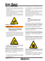
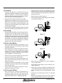
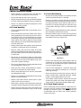
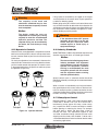
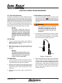
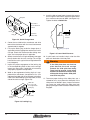
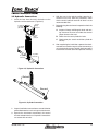
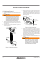
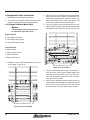
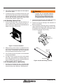
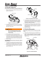
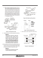
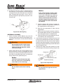
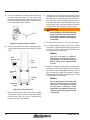
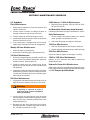
Installation, Maintenance and
Service Manual
LCB, LCC, LCP, LCS,
LCS (Stationary), LFP and LTF
45-006, REV. 7/12
1
TABLE OF CONTENTS
Section 1 Nameplate Location..........................3
Section 4 Service Procedure...........................14
Section 2 Safety Summary................................4
4.1 Attachment Removal............................. 14
2.1 Safety Information.................................... 4
4.2 Arm Removal......................................... 15
2.2 Safety Regulations................................... 4
4.3 Arm Installation...................................... 15
2.3 Safety Symbols........................................ 4
4.3a Arm Retention Pin............................... 15
2.4 Operation Warnings................................. 4
4.4 Cylinder Removal.................................. 16
2.5 Hydraulic Hazards .................................. 4
4.5 Cylinder Installation............................... 17
2.6 Electrical Hazards.................................... 5
4.6 Cylinder Disassembly............................ 17
2.7 Maintenance Warnings............................ 5
4.7 Cylinder Inspection................................ 18
2.8 Training.................................................... 6
4.8 Cylinder Assembly................................. 18
2.9 Labeling................................................... 6
4.9 Hydraulic Valve Removal....................... 19
2.10 Pre-start Checks.................................... 6
4.10 Hydraulic Valve Installation.................. 20
2.11 Personnel Safety.................................... 6
4.11 Repair-In-Place Wear Strip.................. 20
2.12 Load Handling....................................... 7
2.13 Load Positioning.................................... 7
4.12 Camber Adjustment For Articulating Arm
Carton Clamps
21
2.14 Truck Requirements............................... 7
2.15 Operator’s Controls ............................... 9
4 . 1 3 To e A d j u s t m e n t F o r A r t i c u l a t i n g
Arm Carton Clamps 21
2.16 Industry Standards................................ 9
4.14 Rotating Contact Pads......................... 22
2.17 Clamp Open Control.............................. 9
4.15 Pinion/Ring Gear and Bearing............. 22
4.16 Gearbox Lubrication............................ 23
4.17 Gearbox Disassembly.......................... 23
4.18 Gearbox Assembly.............................. 28
4.19 Motor Disassembly.............................. 28
4.20 Motor Assembly................................... 31
Section 3 Installation Procedure.....................11
3.1 Truck Requirements............................... 11
3.2 Carriage................................................. 11
3.3 Hydraulics.............................................. 11
3.4 Attachment Installation.......................... 11
3.5 Hydraulic Connections........................... 13
2
Section 5 Maintenance Schedule....................35
5.1 Schedule................................................ 35
5.2 Schedule, Stationary Load Inverter....... 35
5.3 Torque Specifications............................. 36
45-006, REV. 7/12
SECTION 1 NAMEPLATE LOCATION
Notice
When you receive your attachment, locate the Long Reach nameplate (upper left corner on
the body). Record the information from the nameplate, along with the date received, at the
bottom of this page. If the nameplate is missing, look for the serial number stamped directly
into the metal at the nameplate location and consult the factory for details.
A
Approx nameplate
location
Date received:
-
45-006, REV. 7/12
-
3
SECTION 2 SAFETY SUMMARY
2.1 Safety Information
Safety is Everyone’s Responsibility
Whether you are new on the job or a seasoned veteran,
these safety tips may prevent injury to you, to others, or
to the materials you are handling. Always be alert, watch
out for others, and follow these suggestions:
Attachments handle material, not
people.
Safety starts with common sense,
good judgement, properly maintained
equipment, careful operation, and
properly trained operators.
The safety instructions and warnings, as documented
in this manual and shipped with the machine, provide
the most reliable procedures for the safe operation and
maintenance of your Long Reach attachment. It’s your
responsibility to see that they are carried out.
2.2 Safety Regulations
Know your company’s safety rules. Some companies
have site-specific directions and procedures. The methods outlined in your operator's manual provide a basis for
safe operation of the machine. Because of special conditions, your company’s material handling procedures may
be somewhat different from those shown in this manual.
2.3 Safety Symbols
The following terms define the various precautions and
notices:
Danger
Indicates a hazardous situation which,
if not avoided, will result in death
or serious injury. Carefully read the
message that follows to prevent
serious injury or death.
4
Caution
Indicates a hazardous situation which,
if not avoided, could result in minor or
moderate injury, or equipment damage
or void the machine warranty. Carefully
read the message that follows to prevent
minor or moderate injury.
Notice
Describes information that is useful
but not safety related.
Caution
All possible safety hazards cannot be
foreseen so as to be included in this
manual. Therefore, the operator must
always be alert to possible hazards
that could endanger personnel or
damage to the equipment.
Obey the following warnings before
using your machine to avoid equipment
damage, personal injury or death.
2.4 Operation Warnings
• You must be trained to operate this equipment prior
to operation. Be extremely careful if you do not normally operate this machine. Reorient yourself to the
machine before starting, then proceed slowly.
• Always operate an attachment from the driver’s seat.
• Always lower the attachment if you need to leave the
lift truck. A lift truck supporting a load requires your
full attention.
2.5 Hydraulic Hazards
Warning
Danger
Indicates a hazardous situation which,
if not avoided, could result in death
or serious injury. Carefully read the
message that follows to prevent
serious injury or death.
Small hydraulic hose leaks are extremely
dangerous, and can inject hydraulic oil
under the skin, even through gloves.
Infection and gangrene are possible
when hydraulic oil penetrates the skin.
See a doctor immediately to prevent loss
of limb or death.
45-006, REV. 7/12
• Wear personal protective equipment, such as gloves
and safety glasses, whenever servicing or checking
a hydraulic system.
• Include attachments in a scheduled maintenance
and inspection program. Tailor inspection steps to
the attachment.
• Assume that all hydraulic hoses and components
are pressurized. Relieve all hydraulic pressure before
disconnecting any hydraulic line.
• Unless specified in service procedures, never attempt
maintenance or lubrication procedures while the machine is moving or the engine is running.
• Never try to stop or check for a hydraulic leak with any
part of your body; use a piece of cardboard to check
for hydraulic leaks.
• Always perform all maintenance and lubrication procedures with the machine on level ground, parked
away from traffic lanes.
Notice
Local laws and regulations may require
that additional safety measures be
taken.
2.6 Electrical Hazards
Warning
Remain at least 25 feet from high
voltage electrical wires. Failure to do
so may result in injury or death and
will damage equipment.
• All electrical cables and connectors must be in good
condition (free of corrosion, damage, etc). Use caution in wet weather to avoid danger from electrical
shock. Never attempt electrical testing or repair while
standing in water.
• Never rely on the hydraulic system to support any
part of the machine during maintenance or lubrication.
Never stand under a component that is supported
only by the hydraulics. Make sure it is resting on its
mechanical stops or appropriate safety stands.
• Use caution when working around hot fluids. Always
allow lubricating and hydraulic oils to cool before
draining. Burns can be severe.
• Use extreme caution when using compressed air to
blow parts dry. The pressure should not exceed 30
psi (208 kPa) at the nozzle. Never use compressed
air on yourself. Air pressure penetrating your skin
can be fatal.
• Engine exhaust fumes can cause death. If it is necessary to run the engine in an enclosed space, remove
the exhaust fumes from the area with an exhaust pipe
extension. Use ventilation fans and open shop doors
to provide adequate ventilation.
• Do not wear electrically conductive jewelry, clothing,
or other items while working on the electrical system.
2.7 Maintenance Warnings
Maintenance, lubrication and repair of this machine can
be dangerous unless performed properly. You must have
the necessary skills and information, proper tools and
equipment. Work in a method that is safe, correct, and
meets your company’s requirements.
• Do not attempt to make adjustments, or perform
maintenance or service unless you are authorized
and qualified to do so.
45-006, REV. 7/12
• Before disconnecting hydraulic lines, be sure to lower
all loads and relieve all hydraulic pressure. The load
could fall on you, or escaping hydraulic oil could cause
severe personal injury.
• Prevent personal injury or equipment damage by using a lifting device with a lifting capacity greater than
twice the weight of any equipment to be lifted.
5
2.8 Training
• Make sure all operators are trained in the fork and
attachment adaptation, operation, and use limitations.
Retrain an operator if a new attachment is added to
the forklift. Consult the operator’s manual for instructions on how to use the new equipment.
• Know the mechanical limitations of your forklift.
• Keep hands, feet, long hair and clothing away from
power-driven parts. Do not wear loose fitting clothing
or jewelry while performing maintenance and lubrication in these areas.
• Never jump on or off the machine.
• Never stand on top of material being raised, lowered,
or transported. (Figure 2-1)
• Modifications or additions that affect capacity or safe
operation must have prior written approval from the
forklift truck manufacturer. Capacity, operation, and
maintenance instruction plates, tags, or decals shall
be changed accordingly.
• Never use free rigging for a below-the-forks lift. It could
affect the capacity and safe operation of a lift truck.
2.9 Labeling
• Change capacity, operation, and maintenance instruction plates, tags, or decals when a forklift truck is
equipped with an attachment. If the truck is equipped
with front-end attachments other than factory installed
attachments, truck must be marked to identify the
attachments and show the approximate weight of
the truck and attachment combination at maximum
elevation with load laterally centered.
Figure 2-1
2.10 Pre-start Checks
• Check your equipment before you operate it. If anything looks wrong, unusual or different, report it before
using the attachment.
• Do not operate this machine if you know of malfunctions, missing parts, and/or mis-adjustments. These
situations can cause or contribute to an accident or
damage to the machine. Stop the machine immediately if problems arise after starting.
Figure 2-2
• Check to make sure the attachment on your truck is
the same as on the truck capacity plate.
• Check for hydraulic leaks and cracked hoses or fittings. Check the hydraulic oil level in the lift truck
hydraulic reservoir.
• All electrical cables and connectors must be in good
condition. Use caution in wet weather to avoid danger
from electrical shock.
• Always check the attachment for proper fit and engagement of the truck carriage.
2.11 Personnel Safety
• When removing or installing dismountable attachments always keep hands and feet free from
dangerous positions or pinch points. Never leave a
dismounted attachment in a dangerous position.
6
Figure 2-3
• Never use the attachment or its load to support a
man-carrying device.
• Never allow anyone under a load or under the carriage. (Figure 2-2)
• Never stand in front of or beside an attachment that
is being operated. Never allow another person to approach an attachment that is being operated. (Figure
2-3)
• Never leave an attachment or load in an elevated
position.
• Never reach through the mast of the truck. Keep all
parts of the body within the driver’s compartment.
45-006, REV. 7/12
• Always operate an attachment from the operator’s
seat, never while standing next to the lift truck.
• Do not allow riders on the truck at any time.
• Always use reverse when carrying a load that impedes
full vision. Watch for pedestrians when transporting.
2.13 Load Positioning
• Be accurate in load placement. It’s important to know
what the load will do when it’s released.
2.12 Load Handling
• Always carry loads as close to the floor as possible,
consistent with the surface being traversed. Scraping
or bumping the floor surface with the load or the attachment can severely damage the attachment and
cause product damage. The mast should be tilted
back.
• Treat an unloaded forklift with an attachment as partially loaded.
• Always keep the load positioned as close as possible
to the horizontal center of the lift truck.
• Never overload the attachment. Refer to the attachment nameplate for the rated capacity of the attachment. Refer to the truck nameplate for the maximum
net working capacity of the truck/attachment combination. Never use a load to support or move another
object. Doing so can easily exceed the holding capacity of the attachment.
• Always back down ramps or inclines. Driving forward
down a ramp or incline with a clamped load will lessen
the stability of the truck. (Figure 2-4)
• Always use personal protective equipment (PPE)
appropriate to the situation.
• Always check loads to be handled. Correct loads that
are broken, unbalanced, loose, or too heavy.
• Never lift, lower, side shift, pivot, rotate, or tilt loads
while traveling. Repositioning loads while traveling affects the stability of the truck and may impede vision
or clearances.
• Do not use an attachment to open or close boxcar
doors. Doing so can severely damage the attachment
and cause loss of warranty. Damage to clamp arms
may result in product damage.
• Do not carry loose items or unsupported loads on top
of a clamped load. (Figure 2-5)
• Never use chains, cables, or other devices in conjunction with an attachment for load handling.
• Never clamp loads other than what the attachment
was designed to handle.
• Always carry cylindrically shaped loads in the vertical
position, not the horizontal.
• Always clamp loads with the contact pads, if applicable, not the arm or arm base.
• Never rotate a load that is off center to the centerline
of rotation. Severe damage to the rotator could result.
• Always ensure that the load is the same width as the
pallet and neatly stacked when using a carton clamp.
45-006, REV. 7/12
Figure 2-4
• Do not cross dock boards or dock levelers with the
attachment or carriage fully lowered. Ramming the
front or rear of the attachment against a dock board
can cause severe damage.
• Limit lift truck movement to a minimum when high
stacking. Limit sideshift movement to a minimum
when high stacking.
• Always be observant when high stacking. Look for
poorly stacked loads, overhead obstacles, broken
cartons, or damaged products in the stack.
• Travel slowly around corners. Sound horn on blind
corners. Be careful of tail swing and overhead clearances. Watch in all directions. Avoid sudden stops.
2.14 Truck Requirements
Prior to connecting the truck hydraulic system to the attachment, the truck hydraulic system must be cleaned
through the filtration system. This will eliminate any
contamination that may exist in the auxiliary hydraulic
system of the truck.
7
X
X
X
Figure 2-5
8
45-006, REV. 7/12
Warning
The capacity of the truck and
attachment combined may be less
than the attachment capacity. Consult
truck nameplate!
Notice
The dealer and/or the user are
responsible for installing any valving
required to meet the recommended
hydraulic pressures and flow. The
required valving can be furnished by
the dealer, the truck factory or Long
Reach.
Lifting speed is controlled by the speed of the engine
and the position of the control lever. Engine speed has
no effect on lowering speed.
Before going on the job, shift the truck control levers one
way and then the other to determine which direction the
attachment moves when the levers are shifted. Make sure
the attachment moves smoothly throughout its travel,
without binding or pinching hoses.
Warning
If the attachment does NOT operate
smoothly, do not take it on the job.
Check with your supervisor about
needed repairs to avoid injury or
equipment damage.
2.15 Operator’s Controls
2.16 Industry Standards
Some lift trucks are equipped with a single lever to control
both hoist and tilt functions, others have separate levers
for each function. Refer to your lift truck manual for more
information.
ANSI/ITSDF B56.1-2009 is the published sequence and
direction standard for lever- and hand-type controls.
For clarity, the direction of arm movement is shown on the
control handle. To move the arms in the direction shown,
pull the handle towards the operator. To move the arms
in the opposite direction, the push the handle away from
the operator. (Figure 2-6)
Notice
The chart on the following page shows
industry standards. Your equipment
may be different. If you do not routinely
operate this equipment, refresher
training is recommended. You must
reacquaint yourself with this manual
and the equipment before starting,
and then proceed slowly.
Special controls such as automatic devices should be
identified, preferably according to the recommendations
in Figure 6.
Clamp
Fork position
When a function is controlled by a pair of push buttons,
they should operate in the same sense as the lever controls. For example, pushing a button located to the rear
(relative to the operator’s position) should serve the same
function as moving a control lever to the rear.
2.17 Clamp Open Control
Push/pull
Rotate
Sideshift
Figure 2-6 Operator Controls
45-006, REV. 7/12
Effective October 7, 2010, a new safety standard (ANSI/
ITSDF B56.1, Section 7.25.7) for all lift trucks with a
load bearing clamp (paper roll clamp, carton clamp,
etc.) requires the driver to make two distinct motions
before opening or releasing the clamp. For example,
you must press a switch and then move a lever to
unclamp the load. This requirement applies to new
and used attachments being mounted on new trucks
shipping from the factory after October 7, 2010, and is
a recommended feature to be installed on dealer orders
and existing applications.
9
Direction of motion
Function
Load
Hoist
Reach
Tilt
Sideshift
Push-pull
Rotate, lateral
Rotate, longitude
Load stabilizer
Swing
Slope
Fork position
Trip
Grip
Truck stabilizer
Clamp
Operator's hand on control handle,
facing the load*
Up Rearward or up
Down Forward or down
Retract Rearward or up**
Extend Forward or down
Rearward Rearward or up**
Forward Forward or down
Right Rearward or up
Left Forward or down
Rearward Rearward or up**
Forward Forward or down
Clockwise Rearward or up
Counterclockwise Forward or down
Rearward Rearward or up
Forward Forward or down
Down Rearward or up
Up Forward or down
Right Rearward or up
Left Forward or down
Clockwise Rearward or up
Counterclockwise Forward or down
Together Rearward or up
Apart Forward or down
Engage Rearward or up
Release Forward or down
Engage Rearward or up
Release Forward or down
Raise Rearward or up
Lower Forward or down
Clamp Rearward or up
Release Forward or down
* For high lift order picker trucks and center control pallet trucks, predominant motion of the operator's hand when
actuating the control handle while facing away from the load.
** The sense of rotation of the control handle is intended to be in the same direction as the desired motion of the
mast or load.
Figure 2-7 ANSI/ITSDF
Sequence of location and direction of motion for lever- or hand-type controls
10
45-006, REV. 7/12
SECTION 3 INSTALLATION PROCEDURE
3.1 Truck Requirements
3.4 Attachment Installation
Long Reach attachments have been designed to operate within specific limits. Operating pressures above the
stipulated maximum may cause structural damage to the
attachment and may result in loss of warranty. Hydraulic
flow less than the recommended rates, or the use of small
I.D. hoses may reduce operating speed. Higher flow can
result in excessive heat buildup, erratic operation and
damage to the truck/attachment hydraulic system.
1. Prior to connecting the truck hydraulic system to the
attachment, the system must be purged through the
filtration system. This will eliminate any contamination
that might exist in the auxiliary hydraulic system of
the truck.
Notice
The dealer and/or the user are
responsible for installing any valving
required to meet the recommended
hydraulic pressures and flow. The
required valving can be furnished by
the dealer, the truck factory or Long
Reach.
Warning
The capacity of the truck and
attachment combination may be
less than the capacity shown on
the attachment alone. Consult truck
nameplate!
2. Purging can be accomplished by installing a jumper
line and operating each hydraulic function (clamp,
rotate and side shift if equipped) in each direction
for a minimum of 30 seconds. (Figure 3-1)
3.2 Carriage
1. The truck carriage must conform to the American
National Standard (ANSI) dimensions shown in
ANSI/ITSDF B56.11.4-2013.
2. Make sure the truck carriage is clean, conforms to
ANSI recommendations, and the notches are not
damaged.
To truck
Notice
The model description found on your
shipped invoice will state the following
truck requirements: flow (gpm), psi,
and min. truck carriage width.
3.3 Hydraulics
1. The truck hydraulic system must supply to the attachment hydraulic oil that meets the specifications
required to operate the attachment properly.
2. When the truck hydraulic system pressures exceed
this maximum, a relief valve is recommended in the
attachment auxiliary system of the truck or on the
attachment.
To clamp
Figure 3-1, Jumper Line
3. Remove the lower bolt-on hooks and, if applicable,
make a note of any factory installed shims. Shims
are used to create clearance between the hook and
carriage. If the attachment is equipped with quick
change hooks, simply depress the button on the
back of the hooks, allowing the slide plate to drop.
Removal of the quick change hooks is NOT recommended. (Figure 3-2)
3. Consult the truck factory and/or Long Reach for
guidance.
45-006, REV. 7/12
11
9. Install the bolt-on lower hooks. Inspect clearance to
the carriage on lower hooks. Adjust the lower hooks
for a maximum clearance of 3/32" (see Figure 3-4).
Tighten the bolts to 40-50 ft-lbs.
Slide plate
Raise slide to
secure attachment
to truck.
Button
Body
Push button
to lower slide.
3/32"
maximum
clearance
Figure 3-2, Quick Change Hook
4. Center the truck behind the attachment and drive
toward the attachment with the mast tilted forward
approximately 4 degrees.
5. Line up the locking lug (under the hanger plate, if
applicable) with the appropriate notch on the truck’s
carriage. Check that the bronze side shifting wear
strips are in the proper place, if applicable.
6. Slowly raise the truck carriage completely to engage
the top hooks with the truck carriage. Tilt carriage
back until the unit is against the carriage bottom fork
bar (0 degrees).
7. Inspect for proper engagement of the locking lug
in the corresponding notch of the truck’s carriage.
Inspect any wear strips, if applicable, to insure they
are properly aligned in the top hooks.
8. Weld on the supplemental locking lug that is supplied with the attachment, (two pieces of 1/2 x 1/2 x
2.00 steel included with the attachment) with either
E-6011 or E-6013 welding rod, or equivalent, on each
side of the truck carriage. (Figure 3-3)
YXE4C-307
1/2 x 1/2 x 2.00"
steel supplemental
locking lug
Locking lug
in notch
Shim(s) if required
Figure 3-4, Lower Hook Clearance
10. If quick hooks are installed, simply raise the slide
plate until the button clicks into place.
Warning
If the slide plate does not click into
place because the truck carriage
prevents the slide plate from being
raised up high enough, install shims
between the attachment and the body
of the quick change hooks. Slide plate
must click into place.
11.To ensure proper locking of the slide plate, use a
screwdriver to try to pry down the slide plate. If the
slide plate is not locked in place, inspect and correct
any cause that might restrict the slide plate from
going up enough to allow the button to become fully
engaged.
1/16" clearance
Figure 3-3, Locking Lug
12
45-006, REV. 7/12
3.5 Hydraulic Connections
1. Install the lines from the truck’s hydraulics to the
hydraulics of the attachment. (Figure 3-5)
To truck
supply
(close) V1
To truck V4
secondary
(side shift)
V3
C1 C2
C3 C4
5. Before placing the attachment in operation check the
following:
A. Inspect all hoses and fittings for leaks and routing clearance. Be sure to include clearance of
jumper hoses to the mast.
To truck
supply
(open) V2
B. Check the valve and cylinder for leaks.
C. Check cotter pins at each end of the cylinder for
security.
6. After completing the installation, operate the attachment without a load for several cycles to remove any
air in the hydraulic system. Test the attachment with a
load to make sure the attachment operates correctly.
To cylinder
base end
To cylinder
rod end
4. With the mast in the vertical position, open the attachment arms fully. After this procedure, check
that the truck’s hydraulic reservoir oil level is at the
recommended level.
To cylinder
base end
To cylinder
rod end
Figure 3-5, Hydraulic Connection
Rod end
Base end
Figure 3-6, Cylinder Connection
2. Inspect installation to ensure hoses are not kinked or
pinched between the truck carriage and attachment.
3. Operate the attachment continuously for several
minutes to determine that all hydraulic connections
are secure with no leaks.
45-006, REV. 7/12
13
SECTION 4 SERVICE PROCEDURE
4.1 Attachment Removal
1. Position the attachment arms to the width of the unit’s
body.
Warning
4. Slightly raise the truck carriage to allow the removal
of the bottom mounting hooks. If the attachment is
equipped with quick change hooks, simply press the
slide plate release button and drop the slide plate
down. (Figure 4-2)
Before disconnecting any hydraulic
connections be sure to turn off the
truck’s power and activate the truck’s
hydraulic functions in both directions
to bleed off the hydraulic pressure.
2.
Disconnect the hydraulic connection for the attachment positioning at the hydraulic valve, ports V1 and
V2. (Figure 4-1)
3. Disconnect the side shift connections at ports V3
and V4. (Figure 4-1)
To truck
supply
(close) V1
To truck V4
secondary
(side shift)
V3
C1 C2
C3 C4
To truck
supply
(open) V2
Slide plate
Raise slide to
secure attachment
to truck.
Button
Body
Push button
to lower slide.
Figure 4-2, Quick Change Hook
5. Position the attachment on the edge of a pallet.
Lower the attachment so that the lower carriage bar
misses the pallet when lowered. Tilt the mast forward
to allow the carriage to disengage from the upper
mounting hooks and back away. If lowering onto a
floor, blocks of wood can be placed under the body
of the attachment to raise the rear.
6. To reinstall, follow the installation procedure in this
manual.
To cylinder
base end
To cylinder
rod end
Warning
To cylinder
base end
When hydraulic service has been
performed, activate the hydraulic
functions several times to bleed
out trapped air in the system before
returning attachment to service.
To cylinder
rod end
Figure 4-1, Hydraulic Connection
14
45-006, REV. 7/12
4.2 Arm Removal
1. Extend the arms outside of the body. Remove the
cotter pin retaining the flush nut. Remove the flush
nut. (Figure 4-3)
3. Apply a thin coat of bearing grease to the spherical
portion of the nut and concave section of the arm
lug. Screw on the flush nut until it stops. Back off the
flush nut while lining up the cotter pin hole in the rod
with the slot in the flush nut. Clearance between the
spacer washer and the arm lug should be 1/16 to
1/8 of an inch or less. Do not tighten the flush nut
tight to eliminate all clearance between spacer
washer and arm lug. (Figure 4-4)
Body
1/16 to 1/8 inch clearance
Arm lug
Spacer
washer
Flush nut
Cotter pin
Cotter pin
Arm weldment
Figure 4-3, Arm
Flush nut
Cylinder
rod end
2. Tie the cylinder up to support the weight when removed from the arm lug. Activate the hydraulics and
retract the cylinder from the arm lug.
3. Attach a suitable overhead hoist to the arm weldment.
Pull the arm assembly out of the body.
Figure 4-4, Arm Lug
4. Insert the cotter pin and bend to lock into place.
Notice
4.3a Arm Retention Pin
It is not necessary to remove the arm
assembly to replace wear strips. See
the section on repair-in-place wear
strip replacement.
Retention pins are used only on folding arm bale clamps.
When the arms are folded, these can be installed to
insure that the arms do not open.
4.3 Arm Installation
1. Attach a suitable overhead hoist to the arm weldment. Line up the slide bar with the proper channel
and slide into body.
Remove the retention pin from its storage position on
top of the machine. (Figure 4-5) The pin is attached with
a clevis pin and hair pin to the bracket.
2. Activate the hydraulics and extend the cylinder rod
out until it is at the arm lug. Insert the spacer washer
on the cylinder rod and extend the cylinder through
the arm lug until the arm moves.
45-006, REV. 7/12
15
Retention pin in
storage position
Storage bracket
Bolt to
bracket here
Retention pin in
place with arms
folded (locked
position)
Cotter pin holds
arm hinge pin
Figure 4-5
Follow the illustrated instruction on Figure 4-6 to remove the pin. Installation is the reverse.
3. Rotate and lift
out retention pin
A
2. Lift out
hinge pin
1. Pull cotter pin
Figure 4-6
4.4 Cylinder Removal
1. Extend the arms outside of the body. Remove the cylinder rod end cotter pin and flush nut.
16
45-006, REV. 7/12
2. Tie the cylinder up to support the weight when removed from the arm lug. Activate the hydraulics and
retract the cylinder to the fully closed position.
Warning
Before disconnecting any hydraulic
connections be sure to turn off the
truck’s power and activate the truck’s
hydraulic functions in both directions
to bleed off the hydraulic pressure.
3. Turn off the truck’s power and activate the hydraulic
functions in both directions several times to relieve
built up hydraulic pressure.
4. Disconnect the hydraulic connections.
Warning
When hydraulic service has been
performed, activate the hydraulic
functions several times to bleed
out trapped air in the system before
returning attachment to service.
4.6 Cylinder Disassembly
1. Remove the cylinder from the attachment. See removal instructions.
2. Clamp the cylinder lightly at the base end in a soft
jawed vise. Use a block or other support under the
rod end of the cylinder. (Figure 4-8)
5. Remove the cylinder base end flush nut and cotter
pin.
6. The cylinder now can be removed through the front
of the attachment.
4.5 Cylinder Installation
1. Apply a thin coat of bearing grease to the spherical
portion of the flush nut and concave section of the
body lug. Screw on the flush nuts until they stop. Back
the flush nut off lining up the cotter pin hole in the rod
or base end stud with the slot in the flush nut. Do not
tighten the flush nut tight to eliminate all clearance
between washer and body lug. Adjust to allow 1/16
to 1/8 of an inch clearance between the base end of
the cylinder and the body lug. (Figure 4-7)
1/16 to 1/8 inch clearance
Figure 4-8, Cylinder Vise
3. Use a spanner wrench or similar tool to unscrew the
gland cap from the cylinder tube. (Figure 5-9)
Body lug
Gland cap
Cotter pin
Flush nut
Cylinder
base end
Figure 4-7, Body Lug
2. Turn on the truck's power and activate the positioning
cylinders several times to bleed out trapped air.
45-006, REV. 7/12
Piston
Piston nut
Figure 4-9, Cylinder Rebuild
17
4. Remove the rod assembly from the cylinder tube.
Inspect the piston for:
5. Clamp the rod assembly in a soft jawed vise on the
wrench flats, not on the rod surface. If the rod does
not have wrench flats use two pieces of wood on both
sides of the rod to prevent scarring. (Figure 4-10)
1. Scratches or nicks on seal grooves.
2. Wear on O.D.
Inspect the cylinder rod for:
1. Scratches or nicks on the rod surface.
2. Straightness of the rod.
O-ring
3. Damaged threads.
Inspect the gland cap for:
Seal
1. Scratches or nicks in seal grooves.
2. Damaged threads or spanner wrench holes.
Gland cap
Detail A 3. Excessive wear in bore.
A
Figure 4-10, Cylinder Shaft
Wiper ring
6. Remove the piston retaining nut and remove the
piston. (Figure 4-9)
Replace any component found to be defective.
4.8 Cylinder Assembly
1. Spray the piston, gland cap, and seals with WD40
or other similar product to ease slipping of the seals
in place.
7. Carefully pry up on the piston seals using a blunt
2. Note the direction of the seal on the piston. Improper
tip screw driver being careful not to scratch the seal
installation will result in poor performance. The
grooves. Cut the seals to remove from the piston.
cupped side or O-ring side of the seal should be
Cylinder rod
(Figure 4-11)
facing the gland cap. (Figure 4-12)
Seal
A
Detail A
Locknut
Figure 4-11, Piston Seal
8. Use the same procedure as above to remove the
seals from the gland cap.
4.7 Cylinder Inspection
Inspect the cylinder tube bore for:
1. Deep scratches or nicks.
2. Signs of galling or excessive wear.
3. Out-of-roundness or deformities of the barrel.
18
Piston
Cylinder
rod
Wear ring
Figure 4-12, Piston Seal
45-006, REV. 7/12
3. Install the seals and wipers in the gland cap. Note
the direction of the seals. The cupped side or O-ring
side of the seal should be facing the piston. (Figure
4-13)
2. Disconnect the hydraulic hoses from the truck at the
attachments valve ports V1 (open) and V2 (close).
(Figure 4-14)
To truck V4
secondary
(side shift)
V3
Backup ring
O-ring
Seal
Seal
To truck
supply
(close) V1
A
Detail A
Gland cap
A
C1 C2
Detail A
C3 C4 To truck
supply
(open) V2
Locknut
Wiper ring
To cylinder
Pistonbase end
Cylinder rod
Figure 4-13, Gland Cap Seal
4. Install the piston on the rod and tighten the locknut
to 70-75 ft-lbs.
5. Spray the inside of the cylinder tube with lubricant
to ease inserting the rod and piston. Insert the rod
and piston into the cylinder tube. Tap the rod in with
a rubber mallet if resistance is encountered.
6. Install the gland cap on the cylinder rod being extremely careful not to cut the rod seal on the threads
of the rod or rod shoulder. If available use a sleeve
to cover the rod threads or plastic electrical tape.
F
To cylinder
rod end
Cylinder rod
Wear ring
H
To cylinder
base end
To cylinder
rod end
Figure 4-14, Hydraulic Valve
3. Disconnect the hydraulic hoses at the valve ports
C1, C2, C3 and C4.
4. Remove the valve mounting bolts and remove valve.
7. Tighten the gland cap using a spanner wrench.
4.9 Hydraulic Valve Removal
1. Turn off the truck’s power and activate the hydraulic
functions in both directions several times to relief the
built up hydraulic pressure.
45-006, REV. 7/12
19
4.10 Hydraulic Valve Installation
1. Reassembly in the reverse order above.
2. Turn on the truck’s power and activate the hydraulic
functions several times to bleed out trapped air.
4.11 Repair-In-Place Wear Strip
Notice
It is not necessary to remove the arms
to replace the body wear strips.
2. Do one arm at a time. Remove two wear strip retainer
plugs using your ratchet wrench and extension. The
retainer plug is designed for a 3/8 inch ratchet. The
plug was installed using Loctite at the factory and
may require significant force to break loose.
3. Turn on the truck's power and extend the arms outside the body. The wear strips where the plugs were
removed will then be able to slide out. (Figure 4-16)
Required Parts:
8 - Wear Strip End Pieces
4 - Wear Strip Center Pieces
8 - Wear Strip Retainer Plugs
Tools Required:
1. Rubber mallet
2. 3/8 inch ratchet wrench
3. 3/8 inch extension
4. (Blue grade) Loctite
1. Position the arms to the closed position. Turn off the
truck’s power. (Figure 4-15)
Wear Strip Retainer Plugs
Figure 4-16, Arms Open
4. Raise the attachment and set the arms down on a
stack of pallets, table, or other suitable support and
lower the attachment until the arms just make contact. This will relieve the pressure on the arms side.
Turn off the truck's power.
5. With the arms extended, remove the two remaining
retainer plugs now exposed for the opposite side of
the arm. You can now remove the last end section
of the wear strip. Only the center section remains.
Wear Strip Retainer Plugs
Figure 4-15, Arms Closed
20
45-006, REV. 7/12
6. Insert new wear strip end pieces with the plug hole
first. Insert the wear strip center section. Use the
rubber mallet to tap into channel. Tap the center wear
strip in far enough to leave a lip on the channel to
start the last end piece. Insert the last wear strip end
piece with the plug hole out and tap into place lining
up the retainer plug hole. (Figure 4-17)
3. Negative camber means that the contact pads are
closer together at the top than at the bottom.
4. To help prevent loss of cartons from the lower tier,
LongReach recommends a positive camber of 0.0
to 0.50 inch for pads up to 48 inches high and 0.0 to
0.75 inch for pads over 48 inches high.
5. Camber is adjusted by using 1/8 inch spacers, P/N
Y156057, to increase or decrease camber approximately 1/4 inch on a 48 inch high pad.
6. To increase camber positively, add one or more
spacer(s) between the pad and the lower platen
support. (Figure 4-18)
Top
Upper platen
support
Pivot
Figure 4-17, Wear Strips
7. Prime the retaining plug hole threads with a good
primer following the manufacture’s instructions. Apply
(blue grade) Loctite to the plug threads and torque
plugs to 45-50 ft-lbs.
8. Turn on the truck’s power and raise the attachment
off of the supports. Close the arms.
9. Turn off the truck’s power. Insert the last two plugs
using (blue grade) Loctite and torque to 45-50 ft-lbs.
10. Follow the same procedure for the other arm.
Notice
Do not lubricate the wear strips or
slide assembly. No lubrication is
necessary.
4.12 Camber Adjustment For
Articulating Arm Carton Clamps
1. The term camber refers to the tilt of the contact pads
as viewed directly from the front or rear of the attachment.
2. Positive camber, the desired configuration, means
that the contact pads are closer together at the bottom than the top.
Bottom
Front View
Lower platen
support
Side View
Toe
adjustment
screws
Figure 4-18, Camber And Toe Adjustment
7. To decrease camber negatively, add one or more
spacer(s) between the pad and the upper platen
support.
8. Use existing capscrews only if one spacer is used. If
two or three spacers are used use P/N Y96G-0820
capscrew.
9. As the clamp arms and slides wear it may be necessary to increase the positive camber.
4.13 Toe Adjustment For Articulating
Arm Carton Clamps
1. The term toe adjustment refers to adjusting the difference in the distances between the front edge and
the rear edge of the contact pads.
2. Toe out, the preferred configuration, means that the
front edges are farther apart than the rear edges.
45-006, REV. 7/12
21
3. Toe in means that the front edges are closer together
than the rear edges.
Warning
4. To adjust the toe out, first loosen the lock nuts and
then screw the adjustment screws out (counterclockwise) for greater toe out, in for less. Be sure to adjust
both the top and bottom adjustment screws found
on each platen support. (Figure 5-18)
If gears are not greased properly
premature wear on gears may occur.
Wear on gears may affect performance
or safety and result in loss of warranty.
4.14 Rotating Contact Pads
1. As the contact pads wear it may be necessary to
rotate or replace them. Pad surfaces may wear uneven, more or less, depending on the distribution of
weight in the loads. (Figure 4-19)
2. Grease the pinion/ring gear with Mobil lubricating
grease NLGI grade 2 ISO 220 or equivalent.
3. Grease the ring gear bearings with Aeroshell 22
grease or equivalent.
4. To ensure proper greasing of gears and bearings,
slowly rotate the ring gear 360° while greasing, this
will allow grease to completely coat the gear. Gears
must be fully greased. (Figure 4-20)
Pinion/Ring
Gear Grease
Fitting
Ring Gear
Bearing Grease
Fitting
Figure 4-19, Contact Pad Wear
2. Before rotating, check flatness and deflection of the
pad. The pads surface flatness should not vary more
than 1/8 inch. The horizontal and vertical deflection
of the pad should not be more than 1/4 inch.
Fork arm
shank
3. On articulating clamps, the pads can be rotated left
to right, top to bottom.
4. On adjust-a-force clamps, the pads can be rotated
left to right, top to bottom on standard lengths 42,
48, 54 and 60 inches. On non-standard lengths the
pads can only be rotated left to right.
Grease zerk
Figure 4-20, Grease Fitting Locations
4.15 Pinion/Ring Gear and Bearing
1. Greasing of the pinion/ring gear should be done
every 40 hours. Greasing of the ring gear bearings
should be done every 100 hours. (See Section 6)
22
45-006, REV. 7/12
4.16 Gearbox Lubrication
Part Number: YGC-29, YGC-32, YGC-43 and YGC-43-LH
Top Plug
1. Remove the top plug and the oil level plug from the
gearbox. (Figure 4-21)
Oil Level Plug
Back Plug
Plug
Figure 4-22, Gearbox Grease Plugs
Figure 4-21, Gearbox Oil Plugs
2. Use Mobil HD 85W140 or equivalent oil. If temperatures drop below -20° F, then use a synthetic oil Mobil
SHC 634 or equivalent.
3. Lay the gearbox with the pinion gear down and fill the
gearbox from the top plug hole, allowing trapped air
to escape through the back plug hole, until grease
is present in the back plug hole.
4. To fill gearbox mounted to back plate, fill gearbox from
the back plug hole, allowing trapped air to escape
through the top plug hole, until grease is present in
the top plug hole.
5. Reinstall the plugs.
Warning
Do not overfill gearbox with oil. Doing
so may cause damage to seals and
create leakage.
3. Fill the gearbox to the oil level plug location.
4. The oil level should be checked occasionally at the
oil level plug. If the oil level has dropped, a leak may
have occurred. The leak should be corrected and the
oil should be leveled off to the oil level plug location.
5. Reinstall plugs.
4.17 Gearbox Disassembly
Part Number: YGC-29, YGC-32, YGC-43 And YGC43-LH
1. Remove the attachment from truck. (See Section 4.1)
2. Before removing the gearbox from the back plate,
place a support overhead or under the gearbox.
Remove the mounting capscrews from the gearbox.
(Figure 4-23)
Gearbox
Back Plate
Part Number: YGC-48, YGC-49, YGC-49-LH, YGC-50
and YGC-50-LH
1. The grease in the gearbox will not need to be filled or
changed unless the gearbox itself has been serviced.
2. Remove the top and back plugs from the gearbox
and completely fill with Mobilux EPO or equivalent
grease. (Figure 4-22)
Capscrew
Motor
Figure 4-23, Gearbox Removal
45-006, REV. 7/12
23
3. Place the gearbox on a flat surface and remove the
Motor mounting capscrews.
Pinion gear
Notice
Screwdriver
Coupling fits loose and may slide out.
(Figure 4-24)
Capscrew
Adapter
plate
Key
Gearbox
Capscrew
Capscrew
Motor
Figure 4-25, Adapter Plate Removal
Figure 4-24, Motor Removal
Warning
4. Remove the pinion gear and key from the output
shaft. Use a screwdriver to knock loose the key.
Warning
Do not use a impact wrench on the
screws that have been secured with
Loctite. This could result in rounded
heads or broken sockets.
Use care when taking off the adapter
plate, The gearbox is filled with oil.
6. Drain the gearbox of oil.
7. The output shaft seals may now be serviced.(Figure
4-26)
Seal
Adapter plate
5. Remove the capscrews from the adapter plate. The
adapter plate capscrews are installed with loctite,
use a long handle wrench to break loose. Lightly tap
the back of the adapter plate with a rubber mallet to
remove. (Figure 4-25)
O-ring
Figure 4-26, Output Shaft Seals
24
45-006, REV. 7/12
8. Remove the output shaft assembly. (Figure 4-27)
Motor Adapter
Bearing
O-Ring
Coupling
Shim
Spacer
Worm gear
Capscrew
Shim
Shim
End Cap
Output shaft
Bearing
Shim
O-Ring
Capscrew
Snap ring
Figure 4-27, Output Shaft
Figure 4-29, End Cap/Motor Adapter
9. The output shaft fits tight, you may need to remove
the cap on the back of the gearbox and lightly tap
the end of the output shaft with a rubber mallet to
remove. (Figure 4-28)
11. Remove the input shaft assembly. The assembly fits
tight, use a rubber mallet or press on the extended
shaft to remove. Remove the exposed key with a
screwdriver, allowing the bearing and worm to slide
off of the shaft. (Figure 4-30)
Screwdriver
Key
Bearing
Cap
Bearing
Worm
Snap Ring
Figure 4-28, Output Shaft Cap
10. Remove the end cap and motor adapter. Make note
of any installed shims. Capscrews are installed with
Loctite, use a long handle wrench to break loose.
(Figure 4-29)
Key
Figure 4-30, Input Shaft
12. Reassemble in reverse order. Use Loctite (Blue) on
all capscrews. (See Section 5 for Torque Specifications)
Notice
It is important to get oil to the worm and
worm bearings. Before reinstalling,
dip the worm and worm bearings in
oil for proper lubrication of these
elements. (See Section 4.3)
45-006, REV. 7/12
25
To install pinion gear, heat gear to
250°F to expand I.D. for fit over shaft.
Hold +/- 0.03 dimension. Heat stick
must be used for temp control or
damage to gearbox will occur.
Part Number: YGC-48, YGC-49, YGC-49-LH, YGC-50
And YGC-50-LH
1. Remove the attachment from truck. (See Section 4.1)
2. Before removing the gearbox from the back plate,
place a support overhead or under the gearbox.
Remove the mounting capscrews from the gearbox.
(Figure 4-31)
Motor
Gearbox
4. Remove the capscrews from the gear cap. The gear
cap capscrews are installed with Loctite, use a long
handle wrench to break loose. Using a large screwdriver and hammer separate the gear cap from the
housing. (Figure 4-32)
Warning
Do not use a impact wrench on the
screws that have been secured with
Loctite. This could result in rounded
heads or broken sockets.
Warning
Do not damage machined surfaces of
the gear cap and housing.
5. Remove the pinion shaft assembly. (Figure 4-33)
Pinion Shaft
Gear Cap
Large Bearing
Small Bearing
Shims
Capscrew
Backplate
Figure 4-31, Gearbox Removal
3. Place the gearbox on a flat surface and remove the
motor mounting capscrews. (Figure 4-32)
Capscrew
Capscrew
Worm Gear
Snap Ring
Figure 4-33, Pinion Shaft
6. Remove the snap ring from the end of the pinion
shaft. (Figure 4-33)
7. Place the assembly in a press supporting the gear cap,
not the pinion shaft. Press the pinion shaft through
the small bearing and the worm gear. At this point the
small bearing, worm gear and large bearing are loose
and can be lifted out of the housing. (Figure 4-33)
Warning
Do not drop the pinion shaft onto a
hard surface or it may chip.
Notice
Gearbox
Motor
Figure 4-32, Motor/Gear Cap Removal
26
The small bearing cup in the housing
and the large bearing cup in the gear
cap will need to be removed with a
bearing puller.
45-006, REV. 7/12
8. Wipe as much grease out of the housing as possible
with a rag and inspect for any foreign particles.
Warning
9. The oil seals may now be serviced. Note the orientation of the seals. (Figure 4-34)
Do not damage the machined surfaces
of the worm cap and housing.
Seals
11. The seal in the motor adapter can now be replaced.
(Figure 4-36)
Motor Adapter
Seal
Gear Cap
Figure 4-34, Pinion Shaft Seals
10. Remove the worm cap and motor adapter. Make note
of any installed shims. Capscrews are installed with
Loctite, use a long handle wrench to break loose.
Use a large screwdriver and hammer to separate
the worm cap from the housing. Note any installed
shims. (Figure 4-35)
Capscrew
Figure 4-36, Motor Adapter Seal
12. Using a rubber mallet, lightly tap on the extended
end of the worm gear shaft and remove through the
housing.
Notice
The bearing cup on the motor adapter
side of the housing will need to be
removed with a bearing puller.
Worm cap
Shims
Housing
Capscrew
13. Wipe as much grease out of the housing as possible
with a rag and inspect for any foreign particles.
Motor adapter
Figure 4-35, Worm Cap/Motor Adapter
45-006, REV. 7/12
27
4.18 Gearbox Assembly
Part Number: YGC-48, YGC-49, YGC-49-LH, YGC-50
and YGC-50-LH
1. Install all seals. When replacing seals, use the following suggestions to insure leak-free operation and
long seal life.
A. Cover the keyway and any other surface discontinuity with smooth tape to protect the seal lip
from being damaged.
13. Install the pinion shaft assembly and shims (if applicable). (Figure 4-38)
Pinion Shaft
Gear Cap
Large Bearing
Small Bearing
B. A sealant should be used between the O.D. of
the seal and the I.D. of the bore into which the
seal is installed. The seal bore should also be
free of any burrs, nicks or scratches.
C. Be sure that the seal is not cocked in the seal
bore. The outer face of the seal should be flush
with the surface into which it is mounted.
2. Press on the bearing cup for the worm gear shaft
into the housing on the worm cap side.
3. Install the worm cap and shims (if applicable).
Notice
Use Loctite (blue) on all capscrews. (See
Section 5 for Torque Specifications).
4. Place the bearing cones on both ends of the worm
gear shaft and install into the housing.
5. Press on the bearing cup for the worm gear shaft
into the housing on the motor adapter side.
Shims
Worm Gear
Snap Ring
Figure 4-38, Pinion Shaft Assembly
14. Remove grease plugs and completely fill with grease.
(See Section 4.16)
4.19 Motor Disassembly
1. Remove the motor from gearbox.
2. Place the motor in a vice and clamp across the edge
of the flange with output shaft down. When clamping,
use a protective device on the vise such as special soft
jaws, pieces of hard rubber or board. (Figure 4-39)
6. Install the motor adapter and shims (if applicable).
7. Press on the small bearing cup for the pinion shaft
into the housing.
8. Press on the large bearing cup for the pinion shaft
into the gear cap.
9. Slide the gear cap onto the pinion shaft.
10. Slide on the large bearing cone onto the pinion shaft.
11. Press the gear onto the pinion shaft to the large
bearing.
12. Slide on the small bearing cone onto the pinion shaft
and secure with the snap ring.
Figure 4-39, Motor Clamping
28
45-006, REV. 7/12
3. Remove the capscrews and seal washers (if applicable) from the end cap. The seal on the end cap
can now be serviced. (Figure 4-40)
Seal
Capscrew
6. Remove the output shaft and the needle thrust bearing from the housing.
7. Reposition the motor in the vise. Clamp the motor
across the ports as shown in (Figure 4-43). Do not
clamp on the side of the housing.
Washer
End cap
Figure 4-40, End Cap
4. Remove the gerotor and the drive spacer (if applicable). The seal on the gerotor can now be serviced.
(Figure 4-41)
Drive spacer
Figure 4-43, Motor Port Clamping
Warning
Excessive clamping pressure on the
side of the housing causes distortion.
Seal Gerotor
Figure 4-41, Gerotor
5. Remove the drive and the spacer plate. The seal in
the housing can now be serviced. (Figure 4-42)
Drive
8. Remove capscrews from the mounting flange. These
capscrews are installed with Loctite and will require
300-400 lb-in of torque to break loose and 100 lb-in
of torque to remove.
Warning
Do not use a impact wrench on the
screws that have been secured with
Loctite. This could result in rounded
heads or broken sockets.
Notice
Seal
Spacer plate
If higher torque than given above is
required to break capscrews loose,
apply heat according to the following
instructions.
Figure 4-42, Drive
45-006, REV. 7/12
29
A. When heated, Loctite partially melts. This reduces torque required to remove the capscrew.
Use a small flame propane torch to heat a small
area of the housing where the capscrew enters
(Figure 4-44). Be careful not to overheat the
housing and damage the motor. Gradually apply
torque to the capscrew with a socket wrench as
heat is applied for 8 to 10 seconds. As soon as
the capscrew breaks loose, remove heat from
the housing. Continue turning the capscrew until
it is completely removed.
Heat with a
propane torch
to melt Loctite
Capscrew
Exclusion
Seal
Seal
Pressure Seal
Back-up Ring
Mounting Flange
Figure 4-44, Capscrew Loctite
Back-Up Ring
Mounting Flange
Exclusion Seal
Figure 4-45, Mounting Flange Seals
Bend tip
Radius
Some motors may have a quad seal
and back-up ring in place of the
pressure seal. The quad seal and
back-up ring are no longer available
and are replaced by the pressure
seal. They are interchangeable, but
some precautions must be taken to
insure proper installation. Follow the
reassembly instructions. (Section 4.7)
10. The exclusion seal, back-up ring, pressure seal and
seal will come off with the mounting flange (Figure
4-45). Use a seal removal tool (Figure 4-46 and 4-47)
to remove the exclusion and pressure seals.
Modify
Modify
screwdriver
screwdriver
shown.
asasshown.
Remove
Remove
allallburrs.
burrs.
Radius
on end
Figure 4-46, Seal Removal Tool
11. Work from the outer side for both (either) seals.
9. Carefully remove the mounting flange from the housing.
Notice
Seal
Pressure Seal
Mounting Flange
Pressure Seal
Back-up Ring
Seal Removal Tool
Exclusion
Seal
Figure 4-47, Seal Removal
Notice
Be careful not to scratch the seal cavity
O.D. This could create a leak path.
30
45-006, REV. 7/12
12. A metal plug, with seal, plugs a machining hole in
the housing. It is not necessary to remove the plug
and replace seal unless leakage occurs around the
plug. To remove the plug, insert a 5 mm (.187 in.)
hex key through the port opening and push it out.
(Figure 4-48)
Plug
Notice
Fully cured Loctite resists most
solvents, oils, gasoline and kerosene
and is not affected by cleaning
operations. It is not necessary to
remove cured Loctite that is securely
bonded in tapped holes; however, any
loose particles of cured Loctite should
be removed.
A. Wash the housing with solvent to remove oil,
grease and debris. Pay particular attention to
four tapped holes on the flange end.
B. Blow dry with compressed air. Clean and dry
tapped holes.
Figure 4-48, Housing Plug
4.20 Motor Assembly
1. Check all mating surfaces. Replace any parts with
scratches or burrs that could cause leakage or damage. Clean all metal parts in clean solvent. Blow dry
with air.
Warning
Do not wipe parts with a cloth or paper
towel because lint or other matter
could get into the hydraulic system
and cause damage.
2. Check around the key slot and chamfered area of
the shaft for burrs, nicks or sharp edges that could
damage seals during reassembly. Remove nicks or
burrs with a hard smooth stone (such as an Arkansas
stone). Do not file or grind motor parts.
C. Wire brush screw threads to remove cured Loctite and other debris. Discard any capscrews that
have damaged threads or rounded heads.
D. Wash capscrews with non-petroleum base solvent. Blow dry with compressed air.
3. If you remove a plug or seal, lubricate new seal and
install on plug. Some plugs have two o-ring grooves
but require only one o-ring. Install o-ring in groove
closest to the end of the plug. Push the plug into the
housing so the plug and housing are flush. Be careful
not to damage the seal.
4. Lubricate the output shaft with hydraulic oil, then
install the output shaft into the housing. (Figure 4-49)
Output shaft
Bearing race
Notice
Lubricate all seals with petroleum jelly.
Use new seals when reassembling
motor. Refer to Parts Coverage.
Warning
Do not stretch seals before installing
them.
45-006, REV. 7/12
Lubricate these areas
Needle thrust bearing
Figure 4-49, Output Shaft
Warning
Do not permit oil to get into the four
tapped holes.
31
5. Install the needle thrust bearing, then the bearing
race onto the output shaft. Pull the output shaft
partially out of the housing. Push all three parts into
the housing together (figure 4-50). The bearing race
must rotate freely when in position.
8. Lubricate the I.D. Of the seal tube and O.D. Of the
shaft pressure seal with a light film of clean petroleum
jelly. Align the small I.D. end of the seal tube with the
seal seat in the mounting flange. Install the back-up
ring and pressure seal in the tube with lips of the seal
face up (figure 4-51). Insert the seal driver in the tube
and firmly push seal seat with a rotating action.
Warning
After installing the seal in the mounting
flange, examine the seals condition. If
damaged or improperly installed, you
must replace it before continuing with
reassembly.
Figure 4-50, Output Shaft In Position
9. Install the 49mm (1.937 in.) I.D. seal in the flange.
6. Install the exclusion seal into the mounting flange.
Carefully press the exclusion seal into place. (Figure
4-51)
10. It is recommended to apply a light coat of Loctite
Primer NF in tapped holes of housing. Allow primer
to air dry for at least 1 minute. Do not force dry with
air jet; the primer will blow away.
Notice
Shaft
pressure seal
Seal
driver
Seal tube
Exclusion
seal
Backup
ring
Mounting
flange
Figure 4-51, Seal Installation
7. Visually check the seal seat in the mounting flange
for scratches or other marks that might damage the
pressure seal. Check for cracks in the mounting
flange that could cause leakage.
32
The use of primer is optional.
With primer, Loctite curing time is
approximately 15 minutes. Without
primer curing time is approximately
6 hours.
11. Apply 3 or 4 drops of Loctite sealant at the top of the
threads for each of the four holes in the housing. Do
not allow parts with Loctite applied to come in contact
with any metal parts other than those for assembly.
Wipe off excess Loctite from the housing face, using
a non-petroleum base solvent.
Notice
Do not apply Loctite to threads more
than 15 minutes before installing
capscrews. If the housing stands
for more than 15 minutes, repeat
application. No additional cleaning or
removal of previously applied Loctite
is necessary.
45-006, REV. 7/12
12. Before installing the mounting flange and seal assembly over the shaft, place a protective sleeve or
bullet over the shaft. Then lubricate the space between the exclusion seal and pressure seal, as well
as the lips of both seals. (Figure 4-52)
Apply petroleum jelly across this area
Output Shaft
Dust Seal
This lip to
face inward
Interior of
motor
Notice
If you use new capscrews, make sure
they are the correct length: 22mm
(.875 in.) under head length. See parts
coverage for correct part number.
15. Reposition the motor with the geroter end up, then
clamp the motor across the ports.
Warning
Back-Up
Ring
Pressure
Seal
Seal
Bearing
Race
Figure 4-52, Output Shaft Lubrication
13. Install the mounting flange. Rotate the mounting
flange slowly while pushing down over the shaft. Be
careful not to invert or damage the seals.
14. After removing the bullet, clamp the motor in a vise.
Make sure the shaft cannot fall out. Install dry capscrews and alternately torque them immediately to
250 lb-in. If you use a primer, allow to cure for 10 to
15 minutes. Without primer, allow 6 hours for curing time before subjecting the Motor to high torque
reversals. On all other applications, you can run the
motor immediately. (Figure 4-53)
To aid the installation of seals, apply
a light coat of clean petroleum jelly to
seals. Do not stretch the seals before
installing them in groove.
16. Pour approximately 35 cc of clean hydraulic oil into
the output shaft cavity.
17. Install 73 mm (2.875 in.) I.D. seal into the housing
seal groove. Avoid twisting the seal.
18. Install the drive. Use a felt tip marker to mark one
drive tooth. Align this tooth with the timing dot on the
shaft.
Notice
If the drive is not symmetrical, install
the larger splined end into the shaft.
19. Install the spacer plate.
20. Install 73 mm (2.875 in.) I.D. seal into the gerotor seal
groove. Carefully place the gerotor onto the spacer
plate, seal side toward the spacer plate.
1/2 in. (13mm)
Figure 4-53, Motor Clamping
45-006, REV. 7/12
33
21. For standard rotation align any star point with the
marked tooth on the drive. (Figure 4-54)
24. Install the drive spacer (if applicable).
Gerotor
Gerotor Seal
Spacer Plate
23. Rotate the gerotor to line up the bolt holes. Be careful
not to disengage the star from the drive or disturb
the gerotor seal.
Star
Point
Timing
Dot
25. Install 73 mm (2.875 in.) seal into the end cap. Carefully place the end cap on gerotor.
26. Install the capscrews and seal washers (if applicable)
into the end cap. Pre-tighten the capscrews to 40 lbin. Make sure the seal washers are properly seated.
Then torque the capscrews to 235-250 lb-in.
Housing
Forward
Valving Slot
Figure 4-54, Standard Rotation
22. For reverse rotation align any star valley with the
marked tooth on the drive. (Figure 4-55)
Gerotor
Gerotor seal
Spacer
plate
Star
valley
Timing
dot
Housing
Forward
valving slot
Figure 4-55, Reverse Rotation
34
45-006, REV. 7/12
SECTION 5 MAINTENANCE SCHEDULE
5.1 Schedule
2,000 Hour or 12 Month Maintenance:
Daily Maintenance:
1. Replace oil in the gearbox. (YGC-29, YGC-32, YGC43 and YGC-43-LH)
1. Check level of hydraulic oil in the truck reservoir and
add oil if necessary.
2. Visually inspect all hoses and fittings for wear or
damage. Inspect for signs of hydraulic leaks.
3. Visually inspect for external damage or cracks.
4. Inspect lower hooks for proper clearance. Maximum
clearance is 3/32 of an inch.
5. If the attachment is equipped with quick change
hooks check the slide plate latch for engagement.
Weekly 40 Hour Maintenance:
1. Check for loose or missing bolts.
2. Grease the Pinion/Ring gear. (See Section 4.15)
100 Hour Maintenance:
1. Grease the ring gear bearing assembly and fork arm
shank at zerks. For extreme applications, grease at
40 hour intervals. (See section 4.15)
2. Inspect the body wear strip retainer plugs, do not
tighten, but visually inspect to make sure they have
not loosened.
3. Inspect the cylinder mounting nuts (flush nuts). Apply
wheel bearing grease to spherical portion of the nut
and the concave section of the arm and body lug on
both ends of the cylinders.
5.2 Schedule, Stationary Load Inverter
Follow Daily Maintenance steps in Schedule 5.1 and 5.2.
Daily Maintenance:
1. Visually inspect the hydraulic power unit, rotation
motor, gearbox, and cylinders for leaks.
2. Check the filer gauge and replace if indicated.
100 Hour Maintenance:
1. Check all bolt torques and re-torque if necessary.
2. Inspect all fittings and hoses for wear and/or damage.
250 Hour Maintenance:
Inspect all welds and joints for damage or cracking.
1000 to 1500 Hour Maintenance:
Replace all oil in reservoir after 1000 to 1500 hours
(depending on use).
Hydraulic Power Unit Maintenance:
Refer to the maintenance schedule in the separate Installation and Maintenance Manual included with your power
unit.5.3 Torque Specifications
500 Hour Maintenance:
1. Inspect base and lower retainer for hairline cracks or
signs of structural failure, particularly at the welds.
Warning
If welding is required to make a
structural repair, consult LongReach
before proceeding.
2. Visually inspect ring gear bearing seals to ensure
they are properly inserted into their grooves and that
they are fully intact, preventing contaminants from
entering the bearing.
3. Re-torque the fork bars, front plate and ring gear
bearing capscrews. 5/8 UNF capscrews to 185 ft/
lbs, 1/2 UNC capscrews to 77 ft/lbs.
45-006, REV. 7/12
35
5.3 Torque Specifications
The following torque values are to be used on all fasteners unless otherwise specified.
Lubricated refers to fasteners in the “As Received” condition, which is normally a light preservative oil coating on
unplated fasteners and no oil coating on plated fasteners. No special steps are taken to add further lubrication
prior to assembly. Dry refers to parts that have been
degreased, both mating parts.
GRADE 8 COURSE THREAD
Bolt Size
36
GRADE 5 COURSE THREAD
Lubricated Torque
Bolt Size
SOCKET HEAD COURSE THREAD
Lubricated Torque
Capscrew Size
Lubricated Torque
1/4"
129 in-lbs
1/4"
91 in-lbs
1/4"
150 in-lbs
5/16"
23 ft-lbs
5/16"
16 ft-lbs
5/16"
26 ft-lbs
3/8"
40
3/8"
28
3/8"
46
7/16"
63
7/16"
45
7/16"
74
1/2"
96
1/2"
68
1/2"
115
9/16"
140
9/16"
98
9/16"
160
5/8"
195
5/8"
140
5/8"
215
3/4"
340
3/4"
240
3/4"
385
7/8"
550
7/8"
390
7/8"
615
1"
820
1"
580
1"
920
1-1/8"
1,160
1-1/8"
715
1-1/8"
1,305
1-1/4"
1,640
1-1/4"
1,010
1-1/4"
1,840
1-3/8"
2,150
1-3/8"
1,330
1-3/8"
2,415
1-1/2"
2,850
1-1/2"
1,760
1-1/2"
3,205
45-006, REV. 7/12