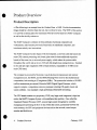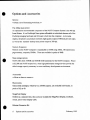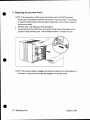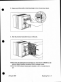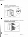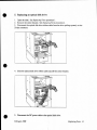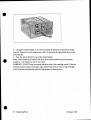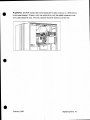
1
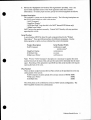
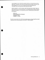
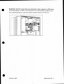
-·
NeXT Extended Service
Program
For NeXT Authorized Service Centers ONLY
-·
i"
...
-
•
I
•
•
This document is CONFIDENTIAL: for use by NeXT Authorized Service Centers ONLY in conjunction with the sale of
Extended Service for NeXT equipment Do not reproduce without written pennission from NeXT, Inc.
Copyright <0 1989 by NeXT, Inc. All Rights Reserved.
NeXT and the NeXT logo are trademarks of NeXT, Inc.
•
Introduction
The NeXT Extended Service Program provides an efficient, low-cost way to extend the
benefits of warranty protection for NeXT products. It is insurance that an owner of NeXT
equipment can buy to eliminate unforeseen repair bills. NeXT Extended Service is an
extended maintenance agreement which covers all hardware maintenance and repairs for
a specified period.
For the Service Center, Extended Service is a profitable, value-added program you can
offer to your customers to help keep them satisfied with their product and your services.
No one likes to pay for an unexpected repair bill, but maintenance contracts like Extended
Service allow you to have positive customer contact every time: A Service Center can
enhance its position with the customer by "watching out" for their interest in
recommending the fixed-cost-of-ownership that Extended Service provides. And the
Service Center can provide an unlimited number of repairs at no charge to further
enhance a positive relationship with the customer. Any repairs performed by a Service
Center on equipment covered by Extended Service are considered "warranty" repairs so
that your work is reimbursed at the standard warranty repair rates.
•
This document provides a NeXT Authorized Service Center with all the information
needed to market, sell, and support NeXT Extended Service. In the following pages
you'll find the following:
•
•
•
•
Data sheet on Extended Service
How to fLll out the Extended Service Agreement form
Inspection requirements for non-warranty equipment
Extended Service Price List.
This is YOUR introduction to NeXT's Extended Service Program. Customers should be
given the "An Intelligent Way to Protect an Intelligent Purchase" document as a user's
introduction to this program.
•
Introdllction
3
Extended Service Data Sheet
•
The following document is available as Point of Purchase material for customers.
NeXT EXTENDED SERVICE PLAN
•
AN INTELLIGENT WAY TO PROTECT AN
INTELLIGENT PURCHASE
The NeXT Computer System is sold with a 90 -day Limited Warranty under which Authorized Service Centers
provide you with any required hardware repairs and maintenance service free of any charge. The NeXT Extended
Service Plans provide an intelligent, low-cost way to extend the benefits of warranty protection for up to a year!
Extended Service is a maintenance agreement which provides you with the peace of mind that comes with fixedcost-of-ownership.
No one likes to pay for an unexpected repair bill. And while NeXT has worked hard to design a powerful and
reliable computer, not every one we make works perfectly, forever ... yet! Unfortunately, hardware repairs after
the warranty has expired can be expensive. Replacing the processor board of a NeXT Computer can cost over
$600. Replacing the optical drive costs over $1000, and a single hard disk repair could cost over $1000, as well.
For less than the average price of a single repair, NeXT's Extended Service Plans cover your investment for an
unlimited number of repairs. No deductible. All the pans, all the labor, is covered. No surprises.
•
4
Extended Service Data Sheet
•
NeXT Extended Service Plans
Terms and Conditions
During the tenn of the Plan, NeXT provides through its Authorized Service Centers across the United States and
Canada, all the remedial maintenance and repair including parts and labor that are required to keep NeXT products
working properly.
Extended Service Plans are available in one-year increments only. They may be purchased at any time: when the
computer is new, or after years of service. If the equipment to be covered is not covered by either a Limited
Warranty or existing, valid Extended Service contract, an inspection to verify its proper function is required.
Service Centers may charge for this inspection.
Currently, three simple Extended Service Plans cover all configurations of the NeXT Computer System. See your
Authorized Service Center for pricing and to purchase your coverage and peace of mind today.
Ext•ndHI S.rvic. Pl~~n•
~~nd Sy• t•m CMflgu,.tl on•
N2000
Pot! No.
•
Q
No.Aa:Bssorin
N9001
~
, (}ptx:dl
N9002
~~ ..
I Oplicai•33CMB
N9003
· ~~·
58001
S8001 6
S8002
S80016
S8001,
88002 6
$8003
$8003
, Op//cd/•6601.18
400dpl
!AsMPrintM
S8001l
$8003
$8001,
58002.
$8003
Service Centers should create their own price list and make it available to customers
interested in purchasing Extended Service Plans. It is a simple enough matrix to provide:
Equipment Description
NeXT Computer
400dpi Laser Printer
Internal SCSI hard disk
•
Plan Number
S8001
S8002
S8003
Service Center Price
$600 + markup
$150 + markup
$300 + markup
Extended Service Data Sheet 5
Ordering Extended Service
•
This document is intended to help you complete the Agreement form quickly and
completely.
Some things to be aware of:
• Use one Extended Service Agreement form for each NeXT Computer System.
• Extended Service may be resold at prices determined by the reseller. Prices listed in
the "Extended Service Price List" are the cost of the plans charged to the Service
Center.
Only NeXT Authorized Service Centers and Resellers may sell Extended Service
Programs for the products they carry.
Each Extended Service Agreement is pre-printed with a unique Agreement number which
is used to track the coverage it provides. Do not photocopy these forms. Additional
Extended Service Agreement forms are available by calling NeXT TeleBusiness at l-800
848-NeXT.
•
As the name implies, the NeXT "One-Year Service Agreement" is a 12-month
maintenance contract for NeXT products. Currently, only one-year plans are being
offered. In the future, monthly and multi-year options could be available as well.
Overview of the Extended Service Order Process
Sell Extended Service to any customer who owns NeXT product by completing the
Extended Service Agreement form. Mail the two NeXT copies of the form with payment
(which may be a Purchase Order) within five days to NeXT Service at the address listed
below. NeXT will invoice you and send the customer confirmation of the Agreement.
•
6
Ordering Extended Service
•
Filling Out the Extended Service Agreement
Follow the steps below to complete the Extended Service Agreement fonn:
2 -
- ___.._________
CJ _, .......__. _ __
__ '-_..,_
4
o--·---· ------
5
~------+----r--r~
-·-·-·---------- -----·----
- - ·--- ...
-==--:::-.;::---···-
•
6==--
===~:.-===---
1. Fill in the "Date of Application." The "One-Year Extended Service Agreement"
fonn (NeXT part number 982) is NOT a contract itself. The contract technically is
not in force until NeXT acknowledges receipt of the completed application to the
customer.
2. Fill in the "Customer" information section completely. The Extended Service
Agreement is essentially an insurance policy for the owner of NeXT equipment. In
order to provide proper service under this agreement, we must have complete
customer information. In the case of institutional ownership of the equipment, a
contact person should be named in this part of the agreement.
3. Fill in the "Service Center" section completely. This section should only be
completed by Authorized Service Centers. If you are not an Authorized Service
Center, you must specify what center will fu lfi ll the terms of the agreement should a
repair be necessary. Call NeXT at 1 800 848-NeXT to get infonnation about the
correct Service Center to list in this section of the agreement.
4. Complete the "Status" section which indicates the conditions of the sale of
Extended Service. If the NeXT equipment is currently covered by the 90-day
•
Ordering Extended Service
7
Limited Warranty or by an existing (valid) Extended Service Agreement, check the
flrst box. If this box is checked, you must provide expiration date and proof of the
Limited Warranty, or the valid Extended Service Agreement number which applies.
•
Limited Warranty proof is a dated sales receipt or delivery receipt showing the
system is still covered by the Limited Warranty. Where no documentation exists,
NeXT may be able to verify warranty status by checking the computer serial number.
If the NeXT equipment is no longer covered by any warranty, an inspection to verify
the proper functioning of the equipment is required. The inspection procedure is
documented below under "Inspection Requirements for Non-Warranty Equipment.".
Service Centers are free to charge the customer for this inspection.
•
•
8
Ordering Extended Service
•
5. Fill out the "Equipment Covered by This Agreement" precisely. This is the
second most important section of the whole agreement (after the Customer
information). To ensure proper records, specify the covered equipment as follows:
Product Description
The customer's system must be described correctly. The following descriptions are
the ONLY names which are valid in this section:
"NeXT Computer"
"MegaPixel Display"
"SCSI Hard Disk" (note that this is for NeXT Internal SCSI drives only)
"400dpi Laser Printer"
NeXT has no other products currently. Contact NeXT directly with any questions
regarding this section.
Serial Number
A serial number MUST be listed for each component listed in the "Product
Description." There are different prefixes for different components. Use the
following table to verify you have collected the correct information:
Product Description
NeXT Computer
MegaPixel Display
SCSI Hard Disk
400dpi Laser Printer
•
Serial Number PrerLX
AAK.xxxxxxx and
AADxxxxxxx*
AAAxxxxxxx
xxxxxxx
AACxxxxxxx
Note: *For the "NeXT Computer" description it is necessary to squeeze the serial
number from borh the back of the cube and the optical drive internally into the small
space. Recording of the optical drive and SCSI hard disk serial numbers will require
opening the back of the cube.
Plan Number
There are three simple Extended Service Plans which can be purchased to cover any
configuration of the system:
NeXT Computer (includes optical drive and any amount of RAM) S8001
S8002
400dpi Laser Printer
S8003
SCSI Hard Disk
The above plans can be combined to cover any NeXT system configuration. The
following table illustrates the combinations:
•
Ordering Extended Service
9
Extended Setvice Plans
•nd System Configurations
•
Part No.
N2000
400dpi
OeiCtlptlon
No Accessories
N9001
1 Optical
N9002
1 Optic<JI+330MB
Laser Printer
S8001
S8001&
S8002
S8001 &
S8003
S8001,
S8002&
S8003
N9003
1 Opticai+860MB
S8001&
S8003
S8001,
S8002&
S8003
Note: One simple Plan, S800l, covers the basic NeXT Computer including the
MegaPixel Display, optical disk drive, and any amount of RAM that is installed on
the processor board (8 to 16MB).
•
Note: The 330MB SCSI hard disk and 660MB SCSI hard disk have the same
Extended Service Plan number. No distinction is made between these drives at this
level.
Price
Pricing is to be determined by the reseller of the Service Agreement. NeXT's prices
for the Extended Service Plans listed above are the cost of the plan to the reseller.
Service Centers are free to create their own retail price list.
Subtotal the agreement coverage.
If applicable, compute the sales tax. Consult you Service Center's tax advisor for the
proper treatment of sales tax on maintenance contracts in your area.
6. You and your customer should sign in the "Acceptance" section. With this, the
fonn is completed. You should collect payment from the customer under whatever
terms you allow.
7. File the gold, "Service Center" copy in a safe place for your reference. Present
the customer with the top, white "Customer" copy and tell them to retain it at least
until they receive the "Acknowledgement of Acceptance" from NeXT, Inc. This
•
10
Ordering Extended Service
•
acknowledgement will confmn the equipment which is covered and the term of the
agreement. It generally takes about four weeks before the customer will receive this
acknowledgement, so any service needed before then should reference the
"Customer" copy of the agreement and the agreement number.
Send the middle two, yellow and pink, copies of the agreement to NeXT within five
days along with your method of payment. For Authorized Service Centers, Purchase
Orders are acceptable, as is pre-payment by check. Extended Service forms should
be returned to:
NeXT, Inc.
Attn: Extended Service Program
760 Mission Court
Fremont, CA 94539
If you have any questions about this form, the order process, or if you'd just like to check
on the status of an existing agreement, call NeXT at 1 800 848-NEXT.
•
•
Ordering Extended Service
II
Inspection Requirements for
Non-Warranty Equipment
•
NeXT equipment which is not covered by either the product's Limited Warranty, or an
existing, valid Extended Service Plan, must be inspected before it can be covered by a
new Extended Service Agreement. This section documents a brief, rudimentary
inspection which will ensure a base-level of functionality of the NeXT equipment.
The inspection documented below is simple, but Service Centers are free to charge
customers an inspection fee for this service. NeXT does not specify this fee.
Equipment which successfully passes the inspection outlined below can be immediately
placed under Extended Service Plan coverage. The inspecting teclmician should signify
this equipment status by checking the appropriate "Status" box and signing his initials.
Equipment which does not pass inspection cannot be covered by an Extended Service
Plan until a non-warranty repair is performed and paid for. Extended Service Agreements
cannot be back dated, or put in-force on any equipment which does not pass inspection.
•
Since the NeXT Computer System is highly modular, you should only perform the
appropriate tests for the configuration .
NeXT Computer Inspection
Goal: Verify the proper functioning of:
NeXT processor board and NeXT-supplied DRAM
Universal power supply
MegaPixel Display
Keyboard and mouse
Optical Drive
Procedure:
1. Perform visual inspection of the system and verify that there are no signs of physical
or electrical abuse, or unauthorized modification of NeXT parts. All serial numbers
must be intact.
2. Connect the NeXT Computer System together and power up with the Power key.
Verify that the fan at the rear of the cube is spinning and the MegaPixel Display raster
is coming on.
3. Verify successful completion of the Power On Self Test. If the system has been
•
12
Inspection Requirements
•
configured not to execute the POST, reset the POST parameter, and restart the
computer.
4. Boot the system from the current software release on optical media.
S. Shutdown the system by logging out, ejecting the media, and powering off.
NeXT Printer Inspection
Goal: Verify the proper functioning of the NeXT 400dpi Laser Printer
Procedure:
1. First complete steps 1 through 4 of the NeXT Computer System Inspection.
2. Verify that at the end of the boot sequence the Laser Printer powers up and the fan
spins.
3. Launch the application /NeXTAdmin/PrinterTester. Verify that the Laser Printer is
"Ready to print." Select a Test Page and click "Print."
4. Verify that printer output is clean, straight, and well-fused .
•
NeXT SCSI Hard Disk Inspection
Goal: Verify the proper functioning of NeXT's internal SCSI hard disks
Procedure:
1. First complete steps 1 through 4 of the NeXT Computer System Inspection.
2. If the SCSI disk is boatable, log out and eject the optical disk, and boot to the
Workspace Manager on the SCSI drive. Shutdown the system and verify the proper
functioning of the SCSI drive.
Instead of using Mach and the Workspace Manager, you can use NeXT Diagnostics as
follows:
2. Shutdown the system to the ROM Monitor and launch NeXT "Diagnostics."
3. Configure the Diagnostics to run as follows:
Flags set: Loop Test = False
SCSI test ONLY enabled
SCSI subtest: Random Read Test Only= 100 loops
Note: If any "write" tests are enabled, the user's data will be destroyed!
•
Inspection Requirements
13
4. Execute the Diagnostic test. The test should take approximately 2 minutes.
Successful completion of the test will be indicated with the message, " DYT passed ... "
•
•
•
14
Inspection Requirements
Extended Service Program Price List
•
NeXT Extended Service is sold directly with direct system sales, and indirectly through
Service Centers and other Authorized Resellers for all other sales. Below are NeXT's
direct pricing for one year of service maintenance on various components of NeXT's
product line. Service Centers and resellers are free to set their own "retail" pricing.
Product Description
E.S. Plan Number
NeXT Price
NeXT Computer System
400dpi Laser Printer
Internal SCSI Hard Disks
S8001
S8002
S8003
$600
$ 150
$300
•
•
CONFIDENTIAL
Extended Service Price List
15
Service Price List
Service Parts
Part no.
Part description
51001
51010
51011
51012
51013
51014
53000
53001
53002
54001
54002
54003
54005
54006
57001
CPU board (no ROM)
fan assembly
lithium battery
universal power supply
backplane PCB
AC power cord
magneto-optical drive
330MB SCSI hard disk
660MB SCSI hard disk
monitor, 1 monochrome
monitor L-board assembly
keyboard
mouse
cube-to-monitor cable
1MB DRAM SIMM
52003
52004
52005
52006
52007
52008
52009
52010
5201 1
52012
52013
52014
52015
52016
AC power inlet assembly
cube-to-printer cable
DC controller PCB
drive assembly
electrical components assembly
fan assembly
fixing assembly
high-voltage components assembly
HV-SG assembly
NeXT interface PCB
laser scanner assembly
paper pick-up assembly
pre-conditioning exposure assembly
transer corona assembly
r
Purchase
Exchange
RSL•·
$4000
$30
$500
2
$10
$275
$75
$10
$2000
$2000
$4000
$750
$475
$225
$100
$75
$40
$1000
$1000
$1200
$300
$100
$100
$50
$375
$100
$150
$100
$350
$150·
$375
$50
$275
$225
$25
$150
$450
$150
$25
$10
$125
$11 0
$350
2
2
2
1
2
1
1
2
$250
$130
$375
One Year Extended Service Plans
•
Plan no.
Equipment Coverage
58001
NeXT Computer (including single optical drive
and any amount of RAM)
400 dpi laser printer
Hard disk drive (330 or 660MB)
58002
58003
Purchase
$600
$150
$300
· Recommended Stocttlng Level per 1000 module Installed base per service center.
rl
NeXT Service Course
•
Outline
Introduction
Welcome
Registration form
Question Collection
Housekeeping
Static Safety
Course Objectives
Documentation
Using the System
Product Description
System Setup
Power on sequence
The NeXT Interface
System Shutdown
nmi Monitor
ROM Monitor
•
Cube Overview
Cube disassembly and re-assembly
Optical and SCSI Drive removal
CPU Board Layout
Diagnostics
Manufacturing Overview
Monitor Overview
Monitor Disassembly
Monitor Troubleshooting and Re-assembly
Printer Overview
Printer Take-apart
Printer Re-assembly
System Troubleshooting Exercise
Service Policy and Procedures
•
How to do business with NeXT
(\
•
NeXT
Service Course
•
•
October 1989
Service Center Master Form
•
Service center name:
Service center type:
Ship-t o
In forma ti o n
Name of institution:
litle/Address1 :
Address2:
Address3:
City:
State/ Province:
Country:
Zip/Postal Code:
Phone1 :
Extension:
Phone2:
•
Fax:
Internet address:
AppleUnk address:
Modem number:
For c u stomers outside th e U.S., please provide th e followi ng:
Phone:
Customs broker name:
B i ll-to
I n form ation
Name of institution:
Attention:
litle/Address1 :
Address2:
Address3:
•
City:
State/Province:
Country:
Zip/Postal Code:
Phonet :
Extension:
I1
•
Accounts
Contact
Payable
Attention:
Title/ Address 1:
Address2:
Address3:
Finance and
Bus iness
Information
City:
State/ Province :
Country:
Zip/Postal Code:
Phone1 :
Extension :
Dun & Bradstreet Number:
Tax Exemption Number:
Method of payment (order requirement):
Will you accept partial shipments?
•
Do you wish to receive statements of account?
Service Center
Personnel
Service center manager:
Service technicians certified to repair NeXT equipment:
Training date:
Name:
NeXT Use
Only
•
Trained by:
Notes:
Date record started: 9/ 18/89
By:
Last updated
LO
•
We at NeXT have tned tO make the infonnation contained in this manual as accurate and reliable as
poss1ble. :-.ievenheless. NeXT disclaims any warranty of any kind. whether express or implied. as to any
mau.er whatsoever relating tO lhis manual. including w1thout limil.aoon the merchantability or fitness for
any paruculat purpose. NeXT will from time tO time revise the training described in this manual and
reseves the right tO make wuch changes without obligation to notify the purchaser. In no event shall NeXT
be liable for any indirect. special. incidental. or consequential damages arising out of purchase or use of lhis
manual or the infonnation contained herein .
•
NeXT. INC. PROVIDES THIS PUBLICATION "AS IS" WITHOUT WARRANTY OF ANY KL'ID.
EITHER EXPRESS OR IMPLIED. INCLUDING. Btrr NOT LIMITED TO. THE IMPLIED
WARRANTIES OF MERCHANTABll.ITY OR FITNESS FOR A PARTICULAR Pt.JR.POSE. Some
states to not allow d.iscl.aimer of express or implied warranties in cen.ain transactions. therefore. this
statement may not apply to you.
This publication could include technical inaccuracies or typographical errors. Changes are periodically made
to this documentation tO reflect the latest service information.
Copyright 0:0 1989 by NeXT, Inc. All rights reserved.
NeXT and the NeXT logo are aademarks of NeXT, Inc. WriteNow is a ttademark licensed to NeXT. Inc.
Linouonic is a registered trademark of Linotype AG and/or its subsidiaries.
Manual written by Herb Philpott
This manual was written and produced using WriteNowrw.
Reorder Product #$6100
•
•
NeXT™
Service Training Guide
First Edition, April 1989
<<Preliminary and Confidential
Do not copy.>>
•
•
•
NeXT Service Course
Objectives
At the conclusion of this class, you will be able to:
• Use the NeXT computing environment.
• Describe the major components of the NeXT systen.
• Identify the serviceable parts of the NeXY system.
• Perform diagnostic tests on all system components.
• Replace any serviceable module according to static-safe procedures.
• Function as a fully qualified NeXT Service Technician.
•
•
•
Introduction
Welcome to NeXT Service Training!
We are very excited that you have joined us in our mission to provide outstanding
service for what we think is an outstanding product. In the next two days, we hope
that you come to share our enthusiasm for the NeXT Computer and its Service.
Conventions
(About this documentation)
•
This is a preliminary Guide to Service Training which utilizes preliminary Service
Documentation. As such, it is fairly well recognized that there is still much more to
come in the way of training material and documentation. For this reason. we ask that
you not make extra copies of this version for distribution. By the next release of
software. this documentation will be released in itS flrst "official" form. Regular
updates will follow, about once every quaner, to keep all the information current.
As in the User Manuals, this documentation employs single angle brackets <like this>
to signify something that is particularly tentative or subject to change. Comments
enclosed in double-brackets, <<like this>>, are authors' notes and items which will
very likely change.
Keep the training guide pages at the front of your Binder. They will be valuable when
you want to train new personnel in your Service Center on how to service the NeXT
Computer.
•
Apri/1989
..............
__________________________
Introduction
3
•
Housekeeping=
The Techman training facility is nearly ideal for our purposes. It is modern, spacious,
and provides all the services we like. It is not ideal, however. since it is not NeXT's
own facility. It is our intention put training facilities right in NeXT buildings in the
future, but for now, since we are after all a stanup company, we will suffer along in
Santa Clara.
There are a few other notes you should know about:
• NeXT is a non-smoking company.
• The Hardware is in beta form. The software is 0.9 release.
• We cherish feedback-SJ's jewels.
Static Safety
Static can kill any high tech device. Employ static-safe service procedures to avoid
damage to the sensitive components of the computers.
•
•
4
Service Training: lnrrodl4Ction
April 1989
•
NeXT
Comp uter Service
First Edition, February 1989
<<Prelimi nary and Confidenti al
Do not copy>>
•
•
I
•
Copyright ' 1988 by NeXT". Inc. All rights reserved.
•
NeXT. INC. PROVIDES THIS PUBLICATION AS IS WITiiOtJr WARRANTY OF ANY KIND.
EITHER EXPRESS OR IMPLIED. INCLUDING. Bur NOT LIMITED TO. THE IMPLIED
WARRANTIES OF MERCHANTABILITY OR FITNESS FOR A PARTICULAR PURPOSE. Some
states to not allow disclaimer of express or implied warranties in certain uansactions, therefore, this
statement may not apply to you .
This publication could include technical inaccuracies or typographical errors. Changes are periodically
made to this documentation to reflect the latest service information.
WARNING: This equipment generates. uses. and can radiate radio frequency energy. and if not installed
and used in accordance with the instruction manual. may cause interference with radio communications. It
has been tested and found to comply with the limits for a Class A computing device pursuant to Subpan J
of Pan 15 of FCC Rules. which are designed to provide reasonable protection against such interference
when operated in a commercial environment Operation of this equipment in a residential area is likely to
cause interference, in which case the user at his or her own expense will be required to talce whatever
measures may be required to correct the interference.
NeXT and the NeXT logo are trademarks of NeXT, Inc. WriteNow is a trademark licensed to NeXT. Inc.
Linotronic is a registered trademark of Linotype AG and/or its subsidiaries.
Manual written by Herb Philpott.
This manual was written and produced using WriteNow on a NeXT Computer and 400dpi LaserPrinter.
ReorderPToductJSOOOO
•
e
•
•
Contents
Product Overview
Product description
Options
Specifications
Theory of Operations
Care & handling
4
Installation
Stand-alone
Network:
Upgrades
Testing
13
Repair
Introduction
Required Tools
Things you should know
Finding the problem
Diagnostic Tests
Replacing parts
Parts list
14
User Software Support
52
February 1989
Contents
3
e
Product Overview
Product Description
<<The following is an excerpt from the Product Piece of 10/8. For this documentation,
things should be a bit drier than this text, but it will do for now. The WHY of this section
is to provide a starting place for technicians who have never heard of a NeXT Computer
as well as for the idly curious.>>
The NeXT Computer combines the best attributes of personal computers and
workstations, adds features previously found only on mainframe computers, and
introduces entirely new innovations.
The NeXT Computer System begins with the Computer, a one-foot cube that houses the
main CPU (central processing unit) board. plus room for three additional expansion
boards of the same size; a universal power supply, which makes the system usable
•
throughout the world; and up to two 5.25-incb full-height mass storage devices. Standard
in the cube are eight megabytes (MB) of main memory, expandable to 16MB on the
main CPU board.
The computer is powered by Motorola s top-of-the-line microprocessor and memory
management unit, the 68030, and the 68882 Aoating-Point Unit for fast mathematical
computation, both running at 25 megahertz (MHz). The system also includes a 10 MIPS
(million instructions per second) Motorola 56001 Digital Signal Processor, which
supports complex. computation-intensive processes including CO-quality music and
sound synthesis. Also standard is high-performance Ethemeto networking.
The CPU board contains two proprietary VLSI (very large-scale integration) chips that
endow the NeXT Computer System with mainframe-like qualities. One, called the
Integrated Channel Processor (ICP), ensures high system throughput by carefully
managing and optimizing the flow of data within the system, particularly between the
main memory, the CPU and peripheral devices such as the network, sound output,
monitor and disk drives .
•
4
Product Overview
February 1989
•
The other VLSI chip, called the Optical Storage Processor (OSP), controls the systems
read/write/erasable 256 Megabyte Optical Disk. The Optical Disk represents a new form
of mass storage technology, combining laser technology and magnetic (Winchester disk)
technology. Information on the Optical Disk can be edited and manipulated, not just
read. and the entire disk can be removed and carried between computers for convenience
and security.
The NeXT Computer System also features the MegaPixel Display, with a 17-inch, crisp,
high-resolution screen. Images on the screen can appear as black, white and various
shades of gray, through the use of two bits per pixel. This shading ability adds depth to
the images that appear on the MegaPixel Display, which in tum adds depth to an
observer s interpretation.
In addition to its visual capabilities, the MegaPixel Display houses impressive sound
capabilities. The system can generate CD-quali.ty stereo sound (i.e., 44.1 kHz, 16-bit
•
two-channel digital audio). Users can listen to the sound through a built-in speaker,
through stereo headphones via a built-in headphone jack or through a connected audio
system via built-in line-out jacks. The Display also features a microphone jack for voice
input. Because the MegaPixel Display derives its power from the cube, it requires no
separate AC plugs or external power sources.
Taken together, the hardware components of the NeXT Computer System create a
powerful, efficient and aesthetic platform that allows users to extend far beyond their
traditional desktop computer boundaries .
•
February 1989
Product Overview 5
Options and Accessories
•
Options:
<<Need a lot of formatting work here.>>
The 400dpi laser printer
An optional but recommended component of the NeXT Computer System is the 400 dpi
Laser Printer. It is a PostScripto laser printer affordable to individuals because all of the
PostScript imaging hardware and firmware is built into the computer. As its name
implies, the printer can produce extremely high-quality output of 400 dots per inch (dpi),
as well as the standard desktop laser printer output of 300 dpi.
Memory Expansion
Memory on the NeXT Computer is expandable to 16MB using lMbit, 100 nanosecond,
page memory, nonparity SIMMs. These are available in packs of 4MB.
•
Mass storage options
NeXT offers both 330MB and 660MB SCSI hard disks for the NeXT Computer. Priced
at $2,000 and $4,000 respectively, these high-performance storage devices provide the
added storage capacity necessary in server and heavy development environments.
Accessories
<<More on these to come.>>
Blank media
Optical disk cartridges, which have a 256MB capacity, are available individually, in
packs of 10, or 40.
MegaPixel Display
Ordered as a separate item, this accessory includes the MegaPixel Display, keyboard,
mouse, and 3-meter display cable.
•
Ethernet Connector Kit
6
Options and Accessories
February 1989
•
This kit includes aT-connec tor, 30 feet (9 meters) of thin ethemet cable, and a
terminator.
•
•
February 1989
Options and Accessories 7
Specifications
•
Computer
Processors
Motorola 68030 25 MHz CPU
Motorola 68882 25 MHz FPU
Motorola 56001 25 MHz DSP
NeXT integrated channel processor
12 DMA channels
32 MB/sec bandwidth
NeXT optical storage processor
Memory
128Kbytes boot ROM
8 to 16MB of memory, user expandable in 4MB increments
256K bytes of dual-ported video RAM
•
Communications and Interfaces
Video monitor interface (DB 19)
Thin wire Ethernet" (BNC), IEEE 802.3 compatible
Two RS-422 serial ports (SCC chip Z8530) with 8-pin mini-DIN connectors
SCSI interface implemented with a 53C90 SCSI chip with transfer rate of 4.8 MB/sec
(burst rate), DB 25 external, 50-pin shrouded vertical header internal
Four enhanced NuBus expansion slots (three after main processor board), type C
Eurocard connector operating at a basic cycle rate of 12.5 MHz, a burst rate of 25 MHz
and a peak transfer rate of 100 MB/sec.
400 dpi Laser Printer pon (DB9) with 5 M bits/sec serial transfer rate
Digital signal processor port (DB 15) with a maximum transfer rate of 2M bits/sec
Power
Powers up to four slots with 25 watts each
Automatically adjusts to line frequency and voltage
Voltage: 90 to 270 volts AC
•
Frequency: 47 Hz to 63 Hz single phase
8
Specifications
February 1989
•
Power: 300 W (including MegaPixel Display)
Clock/calendar
32.768 KHz crystal powered by a 3.0 volt, removable lithium battery
Environment
Ambient temperature: 32j to l04j F (Oi to 40j C)
Relative humidity: 10% to 90% non-condensing
Altitude: 0 to 15,000 feet (0 to 4,500 meters)
Regulations
UL listed and CSA certified
Complies with FCC Part 15 Class A requirements
Size and weight
•
Weight: 25 to 40 lbs ( 10 to 19 Kg) depending on peripheral configuration
Height X width X depth: 12 X 12 x 12 (30 X 30 x 30 em)
Can hold two full-height, 5.25 storage devices
MegaPixel Display
Monitor
17 monochrome, flat screen
1120 x 832 pixels, 2-bit resolution (black, dark gray, light gray, white)
94 pixels per inch
100 MHz video bandwidth
68.3 Hz vertical refresh rate
Input/output
Video monitor interface (DB19) carries +12/-12 VDC, video, and I/0
Keyboard jack, 5-pin mini-din connector
16-bit, 44.1 kHz stereo output through gold-plated RCA phono line-out jacks
Mini-connector stereo headphone jack
•
Integrated speaker <<Do we have specs on the amplifier section>>
8-bit. 8 kHz audio input via monophonic microphone jack <<MIC specs?>>
February 1989
Specifications 9
•
Keyboard/mouse
85-key low-profile keyboard, including cursor keys, numeric keypad, brightness and
volume control, and power on/off
Two-button opto-mechanical mouse
Size and weight
Weight: 50 lbs (23 Kg)
Height X width X depth: 17.3
X
16.0
X
14.0 (44 X 40 X 35 em)
Mass Storage
Magneto-Optical Disk Drive
256 MB (fonnatted)
92 ms average seek time
5 ms average seek time within 5MB range
1.14 MB/sec raw burst transfer rate
0.26 - 0.83 MB/sec raw sustained transfer rate
•
3000 RPM
Infinite read/write/erase
Removable, primary storage and/or backup device
SCSI Hard Disks
Rotary voice coil actuator and integrated SCSI contoller for speed and reliablity
Fonnatted capacities: 330 MB and 660 MB
Average seek time: 14.5 and 16.5 ms respectively
5 and 8 disks respectively
45 KB dual poned FIFO buffer
4.8 MB/sec raw burst transfer rate
3600RPM
•
10 Specifications
February 1989
How the NeXT Computer works
•
<<Very cool stuff will go in here as I explain in technicians and layman s terms (as
opposed to engineers) how our system works. This is fairly high-level, not too detailed,
functional explanation of the computer and its parts. A good Theory of Ops is worth a
thousand pages of troubleshooting diagrams.>>
An understanding of how the NeXT Computer works can provide insight to the
troubleshooting and diagnostic procedures used in the machines repair. This section
provides a brief introduction to the components of the computer and a block diagram of
their function.
When the power switch is pushed, a circuit is completed through the keyboard, keyboardto-display cable, L-board, monitor-to cube cable, to the cube. There is one signal line
•
(PON) dedicated to this circuit.
When PON reaches the processor board, the battery, which has been keeping the
clock/calendar running while there was no AC power, is allowed to relay a PON signal to
pin x of the backplane.
•
February 1989
Specifications 11
•
Care & feeding of the NeXT System
The NeXT Computer is designed to be rugged and reliable, but some care should be taken
to avoid scratching of surfaces. The Cube is coated with a water-based black paint which
can be scratched with sharp objects. Do NOT use solvents such as alcohol, ammonia. or
any abrasives to clean the computer. Repeated use of these will cause the paint to soften
and rub-off. We recommend water-based soap cleaners such as Formula 409".
The computer will operate best in an environment that is out of direct sunlight and other
extreme temperatures. You should not stack the cube on top of the NeXT LaserPrinter,
or put the LaserPrinter on top of the cube. Cubes may be stacked atop one another but
should not be stacked more than three high. Make sure there is adequate air flow through
the bottom of the cube. Currently the fan draws air through the bottom and pushes it out
through the fan grill in the back of the cube. In the future, machines will be configured so
that air is drawn in through the back and forced out through vents in the bottom. If the
•
cube is placed on a shag carpet, it is a good idea to put a piece of cardboard or wood
underneath the computer to prevent excessive dust or fibers from getting inside.
Thumb screws on cable connectors should be tightened fully. Be careful, also, not to
stress or crimp the cables leaving the cube or display too sharply.
The NeXT Computer is designed to withstand normal static conditions. If service work is
being performed with the back of the cube removed, however, full static-safe procedures
should be followed. See Things You Should Know in theRepair.section for more
information.
Do NOT defeat the purpose of the grounded power cord. The three-prong plug should
only be connected to grounded electrical outlets.
NEVER transport a cube with an optical disk inserted in the optical disk drive. Serious
damage can be done to the drive mechanism.
See The NeXT Users Reference Manualfor further information about keeping the NeXT
•
Computer in good condition.
12 NeXT Computer Repair: Care & Handling
February 1989
•
Installation
<<This section should have some more detailed info which would make it a good backup
reference to anyone who ran into some complexity not explained in the UM.>>
•
•
February 1989
Care &: Handling 13
e
Repair
Introduction
<This section covers the troubleshooting and repair of any NeXT Computer failure. This
documentation, combined with your troubleshooting skills, diagnostics NeXT provides,
and on-hand spare pans makes servicing a NeXT Computer a quick and simple operation.
Speed and accuracy are the primary goals of NeXT Service. Speed and accuracy make
satisfied customers, efficient use of your time as a repairing technician, and overall
satisfaction for NeXT.>
<<on-site
module repair>>
•
•
February 1989
Repair 14
•
Required Tools
Tools with part numbers listed below are part of the Service Center Startup Kit, which is
required for every Authorized Service Center. To ensure the correctness of your repairs
use the proper, NeXT-specified tools.
•
•
Description
NeXT part number
Anti-static field service kit
<<PIN requested>>
Anti -static repair pad
<<PIN requested>>
3mm hex driver
<<PIN requested>>
4mm hex driver
<<PIN requested>>
DRAM extractor tool
<<PIN requested>>
Serial loop-back connector
<<PIN requested>>
Ethernet loop-back connector
<<PIN requested>>
Diagnostic Optical Disk
<<PIN requested>>
#2 Phillips blade screwdriver
Part not available from NeXT.
Small flat-blade screwdriver
Part not available from NeXT.
Multimeter
Part not available from NeXT.
February 1989
Required Tools 15
•
Things You Should Know
(Read This Be(ore Every Repair)
Voltage Warning
Electric shock is the most serious hazard to the safety of any computer technician. The
AC power that the computer draws, and the high-voltage components inside the monitor
are the most dangerous parts of the system. Follow standard precautions and heed all
special warnings to prevent shock.
Laser Warning
•
The optical disk drive of the NeXT Computer contains a laser which is regulated by the
Center for Devices and Radiological Health. The Class 1 laser of the optical disk drive
cannot emit levels of optical radiation above exposure limits for the eyes under any
normal condition. There may be more dangerous laser within the protective casing of the
drive but no radiation can escape unless the device is tampered with in an unauthorized
manner.
Static Warning
Electostatic Discharge (ESD) can destroy, or worse, cause intermittent failures in the
sensitive CMOS components of the processor board and other p~. Repairs must be
performed in a static-safe environment
Y Use the anti-static field service kit. part of the Service Center Stanup Kit, properly.
Y A void wearing synthetic or wool clothing.
Y Remove styrofoam and nylon articles from the work area.
Remember that the effects of ESD will usually not be seen right away. Often circuits will
simply be weakened by ESD and will fail weeks, even months, later. Do not leave a
time-bomb with your customer. Follow static-safe procedures!
•
16 Things you should know
February 1989
•
Thermal Caution
Some components-of the NeXT Computer are susceptible to temporary damage from
thermal shock. All modules of the computer system should be allowed to come to room
temperature before being powered up.
Shipping and Handling Caution
The MegaPixel Display and cube are fairly heavy so care should be taken when lifting or
when placing these components on a surface.
When shipping or moving the NeXT Computer, the optical disk canridge must be
removed!
NeXT has gone to great lengths to design packaging for the computer and its parts which
will endure the rigors of shipping. Use it! If you need packaging, order it. See funher
shipping and handling information in the Service Policies and Procedures section.
•
Service Note
<<a word about representing NeXT. Preparation. Paperwork. State of Mind. Work
habits.>>
•
February 1989
Things you should know 17
..............
____________________________
•
Finding the Problem
Introduction
There are three rules and one strong recommendation which, if followed, will make all
your service calls much easier.
Rule 1: Avoid making assumptions.
While an end user description of a problem and your own intuition can be valuable, make
sure you check your assumptions before launching into a repair. Look at the failure
symptoms carefully and use the procedures below to find the root of a problem.
•
Rule 2: Ask good questions.
Be as precise as possible when you ask a user about symptoms. If you ask them, What is
o n the screen? and they might reply, nothing; even though the screen is completely filled
in a dark gray background. And when NeXT s documentation and diagnostic resources
together don t solve a problem, call us and ask us questions. NeXT Technical Suppon is
ready to stand by you in any repair.
Rule 3: Use Known Good Hardware.
Nothing will make a service call longer than faulty replacement hardware or tests. Keep
your spares and diagnostic tools up-to-date and in good working order.
Use the tables on the following pages to efficiently locate any problem in a system.
Recommendation
This is less true for completely dead systems, but in systems where some navigating of
the operating system or applications is required in order to reproduce a failure. you must
have complete access to the machine you must be able to become the superuser on the
machine. nus is simple if the machine owner is present. since they can supply the
necessary passwords. Data can be unavoidably destroyed if you cannot get this security
access to the machine. Make sure the user understands this before you begin your repair.
•
18 Things you should know
February 1989
•
Troubleshooting Flow
The following diagram illustrates the high-level flow of the NeXT Computer
troubleshooting procedure. The four main steps provide staning places for searching out
the symptoms of the problematic computer.
•
Figure x. NeXT Computer troubleshooting diagram.
Each numbered procedure is explained and broken down into a step-by-step approach to
isolate a problem by recognizing certain symptoms. The procedures may refer to tests
which are described in the Tests section. and some procedures will need or ultimately
lead to Replacing Parts to complete a repair.
•
February 1989
Things you should know 19
•
Finding the Problem
Using the Symptom Tables
The tables on the following pages will make it easy for you to quickly locate the solution
to a problem once you ve narrowed it by its symptom. From there you are given all of the
potential causes of that failure symptom roughly in the order of most likely and/or
cheapest and quickest fix to most unlikely and/or most difficult and expensive to fix. Use
known good parts to make narrow down causes quickly.
Problem Type 1: Does the computer power up?
Symptom
•
Cause
What to do
No click is heard when
the power key is
pressed.
1. No power.
A relay in the power
supply should make an
audible click if the battery
supplies voltage to the
power supply.
1. Verify good AC power. Do
other.devices work in the
outlet?
•
20 Things you should know
February 1989
Problem Type 1: Power On failure (cominued)
•
No click is heard when
the power key is
pressed. (continued)
2. No keyboard signal.
The key switches
themselves may be
broken or there may be a
problem with the
keyboard cable.
1. See Test 2: Testing KB
Power-on continuity.
2. Test continuity from cube
back to keyboard connector.
Replace part which causes
failure (starting with cube-tomonitor cable, to monitor Lboard, finally to keyboard)
3. Bad power supply.
The universal power
supply may not be
providing correct output
voltage.
•
I. Check the battery. See Test 2:
Testing the battery. If bad,
replace it.
2. See Test 2: Testing backplane
power signal. If bad, replace
processor board. If still no
go, replace see Procedure 8:
Replacing the backplane.
3. See Procedure 7: Replacing
the power supply .
•
February 1989
Things you should know 21
Problem Type 1: Power On failure (continue d)
•
No dick is heard when
the power key is .
pressed. (continue d)
4. Bad power supply load.
The switching universal
power supply only
operates when it is
properly loaded. A
problem with the monitor
load (the biggest in the
system) could make the
entire computer appear
dead.
1. Replace the monitor cable.
2. Replace the monitor.
•
The fan doesn t spin, but
a click is heard from the
cube•
l. Bad fan.
If the click is heard and
everything powers up
except the fan, it is the
Likely culprit.
1. See Procedure 2: Replacing
the fan.
2. Bad power supply.
It is also possible that the
power supply, though
generally working, is not
supplying correct voltage
to the fan.
1. See Procedure 7: Replacing
the power supply.
•
Monitor doesn t come
22 Things you should know
February 1989
Problem Type I : Power On failure (continued)
•
on, but click is heard
and fan is spinnin.g.
1. Screen brightness could
be at 0.
1. Click the brighter key
repeatedly until the screen
can be seen clearly.
The possible causes which continue below can be quickly soned with a known-good
monitor or known-good cube. If the original cube works with a known-good monitor, see
causes 2, 3 and 4. If the original monitor works with a known-good cube, then see causes
4 and 5.
2. Bad cube-to-monitor
cable.
l. Replace the cable.
3. Bad L-board. Highvoltage, flyback circuitry
is not correct
•
I. See Procedure 9: Replacing
the L-board.
4. Bad CRT. The tube,
itself, is not displaying
the video signal.
1. Replace the entire monitor.
5. Bad processor board. The
board may be sending a
totally black signal.
I. See Procedure 3: Replacing
the processor board.
6. Bad power supply. The
monitor may not be
getting correct voltage.
1. See Procedure 7: Replacing
•
the universal power supply.
February 1989
Things you should know 23
Problem Type 1: Power On failure (continued)
•
Monitor displays bars,
strange patterns,
garbage on screen.
1. Bad processor board.
Often. such wallpaper can
be attributed to a problem
in the video signal created
by the processor board.
1. See Procedure 3: Replacing
the processor board.
2. Bad L-board.
There is a problem with
the video circuitry in the
monitor.
1. See Procedure 9: Replacing
the L-board.
•
•
24 Things you should know
February 1989
•
Problem Type 2: Computer fails power-on self test.
The Power-On Self-Test performs a cursory check of the NeXT Computer every time the
system is powered up or hard reset (<Command-Alternate-*>). The default parameters
perform 13 tests in a few seconds:
1. checksum ROM
2.
3.
4.
5.
6.
7.
checkVRAM
check NVRAM
main memory test
sec test
SCSI test
ethernet check
8. ECC disk chip test
9. real time clock check
10. system timer check
11. event counter check
12. sound out DMA test
13. extended SCSI test (if enabled)
If the Power-On Self-Test detects a failure in the first three tests, it is indicated by an
LED on the processor board visible only when the back panel is removed. Any failures
in the other tests are reported in the Monitor window with an error code listed below.
•
• Error Code Meaning
SCC Channel Tests
50001
Port A SCC/DMA transmit interrupt didn't occur within 0.1 sec
50002
Port A of SCC chip didn't receive loopback char within 0.1 sec
50003
Port A loopback character doesn' t match character sent
50006
Port B non DMA transmit was finished after 0.1 sec
50007
Port B non DMA loopback char doesn' t match the one sent
SCSI Channel Tests
6000 l
FIFO count doesn't match the number of characters loaded
FIFO doesn't contain the data that was loaded
60002
FIFO count doesn't match number of chars left in FIFO
60003
FIFO flush command failed
60004
Counter doesn' t reload
60005
Counter doesn't reload
60006
Configuration register doesn' t work
60007
53C90 doesn't generate interrupt on illegal command
60008
•
February 1989
Power-On Self-Test 25
•
Ethernet Channel Tests
Co~ldn t set physical address
70001
Couldn t drain DMA receive buffer
70002
Physical packet not received
70003
Physical packet was garbled
70004
Received a packet with wrong address
70005
Broadcast packet not received
70006
Broadcast packet was garbled
70007
MO Drive ECC Tests
DMA transfer of raw data to ECC failed
80001
DMA read of encoded data from the ECC failed
80002
DMA transfer of corrupted data back to ECC failed
80003
ECC error count is incorrect
80004
DMA transfer of corrected data from ECC failed
80005
The corrected data is not correct
80006
•
Real Time Clock Tests
The RTC did not tick after 0.3 seconds
9000 1
System Timer Tests
The system timer can not be set
c0002
The system timer interrupt doesn t work
c0003
Sound Out Tests
DMA transfer of sound out data failed
d0001
Event Counter Tests
The event counter did not tick after 100 micro seconds
eOOOl
The event counter is not ticking smoothly; returned value is the ·excessive
e####
delta, (rollover is not an error)
All of the above codes indicate that the processor board is faulty and should be replaced.
See the repair procedure in the Replacing Parts section which follows .
•
26 Power-On Self-Test
February 1989
Problem Type 3: Computer fails hardware diagnostic test.
•
.
See "Using the NeXT Service Diagnostics" for failure code analysis .
•
•
February 1989
Service Diagnostics 27
•
Problem Type 4: Other...
Buzzing or other strange noise is heard from cube.
Keyboard doesn't respond to commands.
Optical drive won't initialize disks.
Optical drive won't accept disks.
Optical drive won't eject disks.
•
Optical drive won 't read disks.
SCSI disk won' t format.
SCSI disk won't spin.
Monitor image is blurred, skewed, or otherwise unacceptable.
Monitor screen rolls. or has "noisy" streaks in iL
No speaker output No audio output from connectors.
Intenninent problems.
•
28 Other Problems
February 1989
•
Diagnostic Tests
1. Power-on Self Test
The Power-On Self-Test performs a cursory check of the NeXT Computer every time the
system is powered up or hard reset (<Command-Alternate-•>). The default parameters
perform 13 tests in a few seconds:
•
•
1. checksum ROM
8. ECC disk chip test
2. check VRAM
3. checkNVRAM
4. main memory test
5. sec test
6. SCSI test
7. ethernet check
9. real time clock check
10. system timer check
11. event counter check
12. sound out DMA test
13. extended SCSI test (if enabled)
If the Power-On Self-Test detects a failure in the flrst three tests, it is indicated by an
LED on the processor board visible only when the back panel is removed. Any failures
in the other tests are reported in the Monitor window with an error code which is dumped
to the ROM Monitor window. (The codes and their interpretations can be found in the
Finding the Problem section, under Problem 2. )
*The test can be modified if one wishes to exercise the cube unattended. To change the
default settings of the Power-On Self Test:
1. Hold down the <Command and ESC> immediately after switching on power to the
computer.
2. At the NeXT> prompt, type p to list the parameters of the system.
3. Type the Return key until the prompt perform power-on test: yes? . This should not
be changed unless there is some failure of the test which is present but not critical and use
of the system is still desired.
4. At the promp~ DRAM tests: this should ~es unless, again, the test is failing and yet
the system is working satisfactorily.
Note: All DRAM SIMMs are not alike. We recommend only NeXT-supplied RAM for
the NeXT system since it has been thoroughly tested for the high-performance
environment of the computer.
5. At the prompt, extended tests: this should bcno unless you suspect a problem
especially in the SCSI area When set to yes, while a SCSI terminator is attached. the self
test time is increased by <20> seconds and the SCSI connector is tested more completely.
February 1989
Diagnostic Tests 29
•
6. At the prompt. loop until keypress: this should b<no unless you want the test to run
continuously to ex~rcise the cube. If it is yes the cube will repeat the self test until a key
is pressed at the keyboard.
7. Verbose test mode allows the status of each part of the self test to be displayed on the
screen. In general, this is not necessary.
Anything less than a perfect test will generate an error code which is interpreted in the
troubleshooting section. Some tests are fatal to the system while others can be disabled if
not critical and the system can be used until a repair is made .
•
•
30 Diagnostic Tests
February 1989
•
2. Diagnostic Software Test
Introduction
NeXT Diagnostic Software is designed to thoroughly test each component of the NeXT
Computer System to verify that it is working properly. In combination with visual
inspection and the Power On Self Test. it will provide a definitive answer as to whether
the hardware of a system is working correctly.
The Diagnostic Software can be loaded from a variety of sources and is executed strictly
from memory. The Mach Operating System and PostScript are not loaded so as to
minimize the amount of interference that these software levels could introduce. The goal
is to have minimal code doing explicit component testing. That is why the Diagnostic
Software has a command line interface.
How to use NeXT Diagnostic Software
•
•
In general, you will start the Diagnostic Software from the Diagnostic Optical Disk since
this can be carried with you on any service calls you make. Alternatively, the test can be
launched from a SCSI hard disk (internal or external) or over an Ethernet network as will
be described below.
1. Power up the cube and interrupt the Power On Self Test process by pressing
Command-Tilde. This will prevent booting (if a boot command was specified),
and display the PROM Monitor window.
2. Insert the NeXT Diagnostic Optical Disk in the optical disk drive of the cube.
3. At the NeXT> prompt, type bodDiagnostic adleturn.
4. You should hear the optical disk spin up, and the screen will soon clear and
display the Diagnostic s main menu at the top of the screen.
5. In most cases it will be necessary for you to modify the tests that are enabled or
disabled according to the configuration of the system you are testing. A brief
description of the tests follows below.
6. Execute the tests by typing e.
7. The test will stop at its conclusion and report its success, or on any error and
report its specific failure. See the section on failure modes Problem Type 3:
Computer fails hardware diagnostic test for an interpretation of the failures and
directions as to the module replacements required.
.
February 1989
Diagnostic Tests 31
•
8. When through with the Diagnostic, you must do a hard reset (CommandAlternate-•) to get back to the PROM Monitor and booring sequence.
NeXT Diagnostic Tests and Submenus
NeXT Diagnostic software tests <n> areas of the NeXT Computer System. Different
tests are appropriate at different times and for different system configurations so before
executing the Diagnostic you must select the specific tests you want performed.
•
•
32 Diagnostic Tests
February 1989
•
3.
a.
b.
c.
d.
Electrical Tests
Testing for continuity on t.he monitor cable
Testing t.he DC output of t.he power supply
Testing the battery
4. Network Tests
•
•
February 1989
Diagnostic Tests 33
•
Replacing Parts
This section covers the replacement of serviceable parts within the NeXT Computer.
Only disassembly instructions are provided here. Unless specifically noted, reverse the
procedures to re-assemble the computer.
Before starting any repair, review the Things you should know section and pay special
attention to the following cautions:
¥
Disconnect AC power to the computer before opening the cube.
¥
Do not remove more parts than are necessary to complete the repair. Note carefully
the location of screws removed during the repair and replace them in their original
locations.
¥
Be particularly careful in handling externally visible parts of the computer. The finish
of the computer can be easily scratched .
•
•
34 Replacing Parts
February 1989
1. Opening the cube
•
-
1. Shut down, switch off, and disconnect AC power to the cube
2. Remove the four hex head screws which secure the rear panel with the 3mm
NeXT hex tool. These are captured screws so loosen them only enough to free the
panel, not enough to remove them completely.
•
•
3. Pull the rear panel straight out from the back of the cube. A fan cable is
connected to the rear panel; make sure you do not stretch this too far.
FebrULJry 1989
Replacing Parts 35
•
•
•
4. Do not unplug the fan cable from the fan unless necessary.
WARNING: Some tests may require switching on the cube with the rear panel
removed. Do NOT operate the cube in this manner for more than 5 minutes .
Serious problems can result from overheating when the rear panel/fan assembly is
not in place.
36 Replacing Parts
February 1989
•
2. Replacing the fan
1. Open the cube. See Replacing Parts procedure 1.
2. Use a flat-blade screwdriver to gently pry up the plastic fan guard.
3. Remove two hex head screws (M4 x 12) which secure the fan to the rear panel,
and remove the fan.
4. When replacing a fan, pay attention to the air flow direction indicated by arrows
engraved in the fan housing and power connector position. Replace in the same
orientation as the fan removed. <Old cubes force air out the back of the cube
while cubes manufactured after January 1989 draw air in from the back.>
<Illustration>
•
•
February 1989
Replacing Parts 37
•
3. Replacing the processor board
NOTE: The high-density, surface mount technology used in the NeXT processor
board make it impossible to perform field service on the board itself. Any attempt
to repair the board except for the procedures listed below will void the warranty of
the processor board.
1. Open the cube. See Replacing Parts procedure 1.
2. Use the ball tip of the NeXT hex tool to hook into the notch at the bottom of the
processor board interface plate. Pull the board out about 1.5 inches (4.0 em) .
•
NOTE: The processor board is plugged with a 96-pin coMector into the backplane of
the cube so it may a fum but steady tug straight out to free the board.
•
38 Replacing Parts
February 1989
•
3. Remove any ribbon cables connecting storage devices to the processor board .
4. Slide the processor board all the way out of the cube.
•
NOTE: If you are replacing the processor board you must remove the ROM from the
defective board to preserve the ethemet 10 of the computer system.
NOTE: The NeXT processor board must be installed in slot 3 as counted from the
left.
•
February 1989
Replacing Parts 39
•
3a. Replacing the NeXT ROM
1. Remove the NeXT ROM from its socket in the defective board and insen it in
the empty slot of the replacement processor board. Make sure the ROM leads get
insened straight into their sockets. Note. too. the offset of the ROM being
removed. 256Kbit ROMs (28-pin) are installed with two sockets open at the
notched end of the ROM.
3b. Replacing the RAM SIMMs
1. Remove the defective RAM SIMM using the extractor tool and replace it with
a new RAM SIMM.
WARNING: There are two different types of RAM SIMMs which can be installed in
the NeXT computer. Each set of four SIMMs must be identical, although sets of
four can alternate between types. <<refer to Upgrades in the Installation section
of this documentation. which doesn t exist yet, for more details of the two different
SIMMs>>
3c. Replacing the battery
1. Remove the old banery from its socket and replace with a new banery making
sure to observe the correct polarity of the new battery.
•
•
<Illustration>
40 Replacing Parts
February 1989
4. Removing the center bracket
•
1. Open the cube. See Replacing Parts procedure 1.
2. Remove all processor boards. See Replacing Parts procedure 2.
3. Remove two hex head screws (M4 x 12) which secure the center bracket at the
bottom- center to the cube.
•
•
4. Use your thumbs as a lever on the outside, top of the cube, and hook your fingers
into the center bracket. Pull the center bracket free from the 96-pin connector which is
holding the bracket with friction inside the cube .
February 1989
Replacing Parts 41
•
5. Once started, the cube should slide out easily.
NOTE: The center bracket (depending on what devices are loaded in it) can be heavyup to 25 lbs ( 12kg.).
•
•
42 Replacing Parts
February 1989
5. Replacing an optical disk drive
•
1. Open the cube. See Replacing Parts procedure 1.
2. Remove the center bracket See Replacing Parts procedure 4.
3. Disconnect the optical disk drive ribbon cable from the drive pulling squarely on the
20-pin connector.
•
•
4. Slide the optical disk drive ribbon cable clip off the center bracket.
5. Disconnect the DC power cable to the optical disk drive.
February 1989
Replacing Parts 43
•
•
•
6. Laying the center bracket on its side will reduce the pressure on the screws during
removal. Remove four hex head screws (M4 x 8) securing the optical disk drive to the
center bracket.
7. Slide the optical disk drive out of the center bracket.
Note: When installing an optical disk drive in the center bracket use only the holes
marked o (for Optical) to secure the drive.
WARNING: DO NOT ship the optical disk drive with a disk cartridge inside! Press the
mechanical eject button in the upper right comer of the drive to remove disk cartridges
which were not automatically ejected in the process of shutting down.
44 Replacing Parts
February 1989
•
WARNING: DO NOT connect the second optical drive cable connector to a SCSI device
in the center bracket. lf there is only one optical drive, only the middle connector in the
drive cable shoullbe used. The end connector should be tucked out of the way.
•
•
February 1989
Replacing Parts 45
•
6. Replacing a SCSI drive
l. Open the cube: See Replacing Parts procedure 1.
2. Remove the center bracket See Replacing Parts procedure 4.
3. Slide the SCSI drive ribbon cable clip off the center bracket
4. Disconnect the SCSI drive ribbon cable from the drive pulling squarely on the 50-pin
connector.
5. Disconnect the DC power cable to the SCSI drive.
5. Laying the center bracket on its side will reduce the pressure on the screws during
removal. Remove four phillips head screws (<designation?>) securing the SCSI drive to
the center bracket
•
6. Slide the SCSI drive out of the center bracket
Note: When installing an SCSI hard disk drive in the center bracket use only the holes
marked H (for Hard disk) to secure the drive.
•
46 Replacing Parts
February 1989
•
WARNING: DO NOT connect the second optical drive cable connector to a SCSI device
in the center bracket. If there is only one optical drive, only the middle connector in the
drive cable should-be used. The end connector should be tucked out of the way.
•
•
February 1989
Replacing Parts 47
•
7. Replacing the universal power supply
1. Open the cube. See Replacing Parts procedure 1.
2. Remove the center bracket See Replacing Parts procedure 4.
3. Disconnect the DC power cables to any peripherals.
4. Remove four hex head screws (M4 x 8) to free the power supply from the center
bracket.
WARNING : There are no serviceable parts inside the NeXT power supply. Opening the
power supply will void the warranty.
<illustration>
•
•
48 Replacing Parts
February 1989
•
8. Replacing the backplane
1.
2.
3.
4.
Open the cube.- See Replacing Parts procedure 1.
Remove the center bracket. See Replacing Parts procedure 4.
Remove the two card guides which snap into the bottom of the cube.
Remove the three hex head screws (M4 x 8) to free the backplane from the cube .
•
•
February 1989
Replacing Pans 49
•
•
9. Replacing the L-board
.
WARNING: The monitor contains high voltage pans and a vacuum cathode ray tube
(CRT). To reduce the risk of serious injury due to shock or CRT implosion, it is
important that you follow the standard instructions which follow carefully. Safety
goggles should be worn to protect your eyes. Jewelry should be removed to reduce the
possibility of electric shock.
Note: The flyback transformer of the monitor has a built-in bleeder resistor, so you do
not need to discharge the high-voltage anode before replacing the L-board. Do not touch
the exposed anode button on the CRT while reconnecting the anode lead. A small spark
(5 or 6 KV) might be seen when reconnecting the anode lead of a new board to a CRT
which has been used for a while.
l. Remove four hex head screws (M4 x 8) securing the back bucket to the monitor, and
remove the bucket.
2. Remove three phillips head screws to free the left access hole cover. Repeat this step
to remove the right access hole cover.
3. Remove the anode cap from the CRT and free the cable from the nylon guide attached
the the monitor chassis.
4. Disconnect two CRT connectors, the cathode and the yoke connector, to the L-board.
5. Remove four phillips head screws securing the top cover to the monitor chassis.
6. Remove six phillips head screws securing the L-board to the monitor chassis.
7. Slide the top of the monitor chassis up enough to dislodge the L-board chassis. Slide
the L-board out, away from the CRT.
<Illustration>
50 Replacing Parts
February 1989
•
•
•
Parts List
-
Item
Description
Part numbe r
1
processor board (no ROM)
SIOOI
2
universal power supply
Sl012
3
fan assembly
S1010
4
lithium battery
Sl011
5
monitor, 17" monochrome
S4001
6
cube-to-monitor cable
S4006
7
backplane PCB
S1013
8
keyboard
S4003
9
mouse
S4005
10
magneto-optical drive
S3000
11
power cord
S1014
12
1MB DRAM SIMM
S7001
13
monitor L-board
S4002
14
330 MB SCSI hard disk
S3001
15
660 MB SCSI hard disk
S3002
February 1989
Parts List 51
•
How To Do Business with NeXT
NeXT has tried to model their Service Program after the best elements of Apple's
and of Sun's ... some examples:
Service
Downtime
Extended Service
Apple
carry in
1 week
1-2%
Sun
onsite
4-6 hours
2-4%
NeXT
on site
less than 6 hours
1-2% (of initial cost)
The Service Center Start-up Kit (SCSK)
NeXT has tried to keep the cost low and VERY available: $8,000, which includes:
•
•
•
•
•
•
•
•
N9001-08 (a complete base system for "known good" tests and parts swap)
- Manuals
Documentation
- Newsletters from the Service Program people
- Updates as released for one year
included for the first person, additional individuals cost $500 each
Training
suggested spares list will be sent, focus on drives and printer parts
Spares
Diagnostics the Optical Disk you take away, and loop-back connectors will be sent
the static mat, 3mm hextool, DRAM extractor
Tools
signs and other materials from Herb Philpott
Collateral
Warranty/Repair
•
90 day Warranty on everything
system and components 90 days from shipment (plus 2 or 3 days)
replacement parts 90 days from installation (no shelf-life problems)
•
Repairs (keep one set of packing boxes just in case)
- you diagnose the problem, replace a part for your customer, call NeXT
and replacement is shipped to you via two day air
upon arrival from NeXT, you return faulty part in the box sent to you
we will follow up with the customer to gauge satisfaction/success/service
•
Service Repair Order (SRO) Forms will be completed (by you) with customer
name, service center info, status [warranty or repair], part numbers [in and
out], Purchase order (a spot for information meaningful to your operation)
Phone Support
•
•
(415)-424-8500 (for your use, NOT your customers')
staffed by skilled, helpful, service oriented people-call and ask them!
•
rl~ .-b
P~~
I p~C-
(:.1 J' s-) .J ~ ' .. o ~ o o