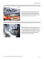
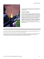
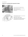
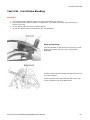
1
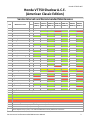
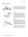
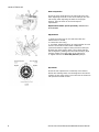
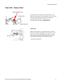
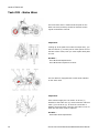
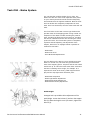
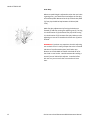
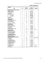
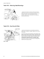
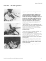
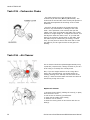
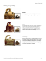
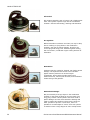
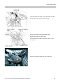
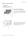
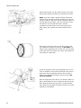
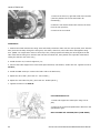
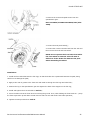
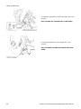
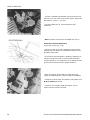
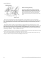
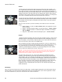
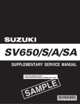
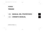
1
9
9
8 -2
0
0
3
Ser
vi
ce I
nt
er
val
s
and
Recommended
Mai
nt
enance
VT7
5
0
C/
CD/
CD2
SHADOW/
SHADOW DELUXE/
ACE
Honda VT750DC ACE Disclaimer: The articles in the “Service Interval and Recommended Maintenance Manual” (this document) and those that may be posted in the forums of the 750ace.com website are meant for information purposes only. These procedures and modifications are not manufacturer approved instructions or modifications and they may not be legal in some municipalities. 750ace.com is furnishing this information “as is”. 750ace.com does not provide any warranty of these articles whatsoever, whether expressed, implied, or statutory, including, but not limited to, any warranty of performance or fitness for a particular purpose or any warranty that the contents of the articles will be error‐free. 2 Service Interval and Recommended Maintenance Manual Honda VT750CD ACE Honda VT750 Shadow A.C.E. (American Classic Edition)
Service Intervals and Recommended Maintenance Task Maintenance Item 01 Drive Chain 1000 km 6400 km 12800 km 19200 km 25600 km 32000 km 38400 km
(600 mi) (4000 mi) (8000 mi) (1200 mi) (16000 mi) (20000 mi) (24000 mi)
Notes: 02 Brake Fluid Inspect & Lube Every 800 km (500 mi) (4) I I R I I R I I I I I I 03 Brake Wear 04 Brake System 05 Brake Light Switch 06 Headlight Aim 07 Clutch System 07 Side Stand I I I 09 Suspension I I I 10 Nuts, Bolts, Fasteners I I I I 11 Wheels/Tires I 12 Steering Head Bearings I 13 Fuel Line 14 Throttle Operation 15 Carburetor Choke I I I I I I I I I I I I I I I I I I I I I I I I I I I I I I I I I I I 16 Air Cleaner (2) R 17 Crankcase Breather (3) C C C C C C I R I R I R R 18 Spark Plugs 19 Valve Clearances I I I I 20 Engine Oil R R R R 21 Engine Oil Filter R R R R 22 Carb. Synchronization I I I 23 Engine Idle Speed 24 Radiator Coolant 25 Cooling System I I I I I I I (4) I I R I I I 26‐31 Replacement Instructions and Adjustments for Brakes, Coolant, and Pilot Screw
I = Inspect C = Clean R = Replace Note 1 : At higher odometer readings, repeat at the frequency interval established here. Note 2: Service more frequently when riding in unusually wet or dusty areas. Note 3: Service more frequently when riding in rain or at full throttle. Note 4: Replace every 2 years, or at indicated odometer interval, whichever comes first. Service Interval and Recommended Maintenance Manual 3 Honda VT750DC ACE 4 Service Interval and Recommended Maintenance Manual Honda VT750CD ACE Table of Contents
Task #01 ‐ Drive Chain .................................................................................................................................................. 7 Task #02 ‐ Brake Fluid ................................................................................................................................................... 9 Task #03 ‐ Brake Wear ................................................................................................................................................ 10 Task #04 ‐ Brake System ............................................................................................................................................. 11 Task #05 ‐ Brake Light Switch ..................................................................................................................................... 13 Task #06 ‐ Headlight Aim ............................................................................................................................................ 14 Task #07 – Clutch ........................................................................................................................................................ 15 Task #08 ‐ Side Stand .................................................................................................................................................. 16 Task #09 ‐ Suspension ................................................................................................................................................. 17 Task #10 ‐ Nuts, Bolts and Fasteners .......................................................................................................................... 18 Task #11 ‐ Wheels & Tires ........................................................................................................................................... 23 Task #12 ‐ Steering Head Bearings .............................................................................................................................. 24 Task #13 ‐ Fuel Line & Filter ........................................................................................................................................ 24 Task #14 ‐ Throttle Operation ..................................................................................................................................... 25 Task #15 ‐ Carburetor Choke ...................................................................................................................................... 26 Task #16 ‐ Air Cleaner ................................................................................................................................................. 26 Task #17 ‐ Crankcase Breather ................................................................................................................................... 27 Task #18 ‐ Spark Plugs ................................................................................................................................................. 28 Task #19 ‐ Valve Inspection / Adjustment .................................................................................................................. 32 Task #20 ‐ Engine Oil & Filter ...................................................................................................................................... 41 Task #21 ‐ Removal & Installation of the Wheels ....................................................................................................... 43 Task #22 ‐ Carburetor Synchronization ...................................................................................................................... 47 Task #23 ‐ Engine Idle Speed ...................................................................................................................................... 49 Task #24 ‐ Radiator Coolant ........................................................................................................................................ 49 Task #25 ‐ Cooling System .......................................................................................................................................... 50 Task #26 ‐ Rear Brake Shoe Replacement .................................................................................................................. 51 Task #27 ‐ Front Brake Pad Replacement ................................................................................................................... 56 Task #28 ‐ Replacing the Coolant ................................................................................................................................ 58 Task #29 ‐ Front Brake Disc Inspection & Limits ......................................................................................................... 62 Task #30 ‐ Front Brake Bleeding ................................................................................................................................. 63 Task #31 ‐ Pilot Screw Adjustment ............................................................................................................................. 65 Service Interval and Recommended Maintenance Manual 5 Honda VT750DC ACE 6 Service Interval and Recommended Maintenance Manual Honda VT750CD ACE Task #01 - Drive Chain
The service life of the drive chain is dependent upon
proper lubrication and adjustment. Poor maintenance can
cause premature wear or damage to the drive chain and
sprockets. The drive chain should be inspected prior to
every day's riding, adjusted for slack when required and
lubricated every 800km or following any riding done in
rain.
Inspection:
Check the slack in the lower drive chain run about
halfway between the sprockets. Ideally you want about
3/4" of play. When the play reaches 1" you need to
adjust the chain tension. Also check for Damaged Rollers,
Loose Pins or Missing O-rings. The chain requires
replacement for any of those. Dry or Rusted links require
immediate lubrication. Kinked or Binding Links require
lubrication and also need to be worked free. If they can't
be worked free then the chain needs to be replaced.
Lubrication:
The drive chain on this motorcycle is equipped with small
O-rings between the link plates. These O-rings retain
grease inside the chain to improve it's service life.
Therefore, it is not a good idea to use high pressure
water or steam cleaning to clean this chain. You should
use an SAE 80 or 90 gear oil or an O-ring safe chain
wax to lube this chain. Personally, I prefer the chain wax
as it does not spray the tire and chain guard and when
applied properly, it makes for less chain noise while
riding.
Before lubing, I ride my bike for 20 mins to warm the
chain up, then I clean my chain with a lightweight oil
such as LPS-1 or 2, using a dry cloth to wipe off the dirt
and excess oil. Then I spray a nice even coat of gear wax
and let it sit for 30 mins before riding.
Service Interval and Recommended Maintenance Manual 7 Honda VT750DC ACE Wear Inspection:
Check the chain wear label on the left-hand swing arm
when adjusting the chain. If the arrow mark(6) is in the
red zone(5) after adjusting the slack to the proper
amount, then the chain is worn and requires
replacement.
Replacement Chain (stock sprocket): DID525V8 or
RK525SMOZ5
Adjustment:
1. Place the motorcycle on it's side stand with the
transmission in neutral.
2. Loosen the axle nut(1).
3. Turn both adjusting bolts(2) an equal number of turns
until the correct drive chain slack is obtained.
(counterclockwise to tighten chain) Roll the motorcycle
forward and check tension again. Then check that the
axle is aligned by making sure the index marks(3) align
with the scales(4) on both sides of the swing arm.
4. Tighten axle nut to 69 ft-lbs (93 N-m) torque.
Sprockets:
Check the rear sprocket for excessively worn teeth or
broken and missing teeth. Use the diagram to the left as
a guide. Do this more often if your bike has an aluminum
rear sprocket instead of steel.
8 Service Interval and Recommended Maintenance Manual Honda VT750CD ACE Task #02 - Brake Fluid
The Brake fluid level should be checked before every
day's ride and during every maintenance cycle. The fluid
should be changed every 2 years or at 19,200 km
(12,000 miles), whichever comes first. The
recommended brake fluid is Honda DOT 4.
Inspection:
With the motorcycle in an upright position, check the
fluid level using the sight glass on the reservoir. If the
level is at or below the LOWER level mark (1), check
your brake pads for wear. If your pads are not worn,
then check your brake system closely for leaks.
- Break Wear Inspection
Service Interval and Recommended Maintenance Manual 9 Honda VT750DC ACE Task #03 - Brake Wear
The front brake wear is measured at the pads on the
brake unit itself, and they should be checked at each
regular maintenance interval.
Inspection:
Looking up at the pads from under the caliper assy, you
will see cutouts (1) on each pad. If either pad is worn to
the base of the cutout, then you must replace both pads
as a set.
See Also...
- Front Brake Pad Replacement
- Front Brake Disc Inspection & Limits
The rear brake is equipped with a brake wear indicator
on the drum itself.
Inspection:
Have someone apply the rear brake. An arrow (1)
attached to the brake arm (2) moves toward a reference
mark (3) on the drum (4). If when the rear brake is
applied, the arrows align, then the rear brake is worn to
limits and the shoes must be replaced.
See Also...
- Rear Brake Shoe Replacement
10 Service Interval and Recommended Maintenance Manual Honda VT750CD ACE Task #04 - Brake System
The 750 ACE has excellent brakes for it's class. The
brakes are also one of the most important safety items
on your motorcycle and should be checked frequently
and maintained to the highest standards. Both the front
and rear brakes are completely independent of each
other and if one should fail, then the other brake will still
work.
The front brake on the ACE is a Disc-type brake and it
provides most of the stopping power during normal use.
Inspection of this brake includes checking the pads for
wear, checking the fluid level of the reservoir, checking
the disc for condition and wear and checking the whole
system for leaks. The front brake system is completely
hydraulic and self adjusting. No adjustment of the
calipers, brake lever or stoplight switch is possible or
needed for this brake.
- Brake Wear
- Brake Fluid Level
- Front Brake Pad Replacement
The rear brake on the ACE is a more simple Drum-style
brake. In normal use, this brake only provides about
25% of the stopping power. Anymore and the rear wheel
would lock up. It is also the brake most often used when
the bike is standing still at a light, for example. It is
inspected for wear at the drum, pedal height and free
play and the stop light switch actuation point.
-
Break
Break
Brake
Brake
Wear Inspection
Light Switch Adjustment
Pedal Height Adjustment
Pedal Free Play Adjustment
Pedal Height: A stopper bolt is provided to allow adjustment of the pedal height. Loosen the locknut (1) and turn the stopper bolt (2). When the height is were you want it, tighten the locknut (1). Service Interval and Recommended Maintenance Manual 11 Honda VT750DC ACE Free Play:
Whenever pedal height is adjusted or when the rear brake is getting worn, you should check and adjust the free play at the brake pedal. Measured at the tip of the brake pedal (3), free play should be kept between 20‐30mm (0.8‐
1.2in). Make free play adjustments by forcing the brake arm forward (5) and then turning the adjusting nut (4). Turning it in the direction of (A) decreases free play while turning it in the direction of (B) increases free play. Make sure the adjusting nut cut‐out is seated on the brake arm (5) when finished. WARNING: It has been my experience that this adjusting nut can back off on it's own (perhaps due to the increased vibration of my aftermarket pipes) and I had a near disaster on the 401 HWY once when it backed off so far that I had no rear brakes. I would recommend installing a second 'jam nut' behind this adjuster. I installed a fiber lock nut as a jam nut and it has not moved at all since then. 12 Service Interval and Recommended Maintenance Manual Honda VT750CD ACE Task #05 - Brake Light Switch
Check the brake light switch operation and adjustment
by applying the brakes with the ignition turned on.
Operation of either the front brake lever or the rear
brake pedal should illuminate the rear brake light.
Note: The front brake light switch is incorporated into
the handlebar lever assy and is not adjustable. If the
switch fails to operate, then you will have to find the
fault and/or replace the switch assembly.
The rear brake switch is adjustable. Proper adjustment of
the switch will have the light coming on just before the
brakes actually engage. Before adjusting this switch,
make sure you have your rear brake pedal height and
free play properly adjusted in accordance with the
instructions.
To adjust the rear brake switch, grasp the switch body
firmly and turn just the adjustment nut. Make sure you
do not allow the switch body itself to turn as the wires
inside can break off. After you have made the
adjustment, double check that it operates properly.
Service Interval and Recommended Maintenance Manual 13 Honda VT750DC ACE Task #06 - Headlight Aim
Headlight aim is very important and should be checked
regularly. A misadjusted headlight might not shine far
enough down the road for you to see properly or it might
be so high that it blinds oncoming traffic. Also, there are
usually regulations in the area you reside about exactly
how a headlight should be aimed and you should review
these before doing any adjustments yourself.
The procedure I have put below is a basic means of
adjusting your headlight and should satisfy most
regulations. If in doubt, get a certified shop to check it.
The first thing you need to do is find a nice level area to
park your bike that has a light colored flat surface about
25 feet in front of it. A driveway and a garage door might
work here, as long as it is level. You also have to be
mounted on your bike to simulate a proper riding
condition when you take your measurements. A buddy
helping you here might be handy.
First, with your weight on the bike and the bike held
upright, take a measurement from the center of your
headlight to the ground. Now go to the wall that is 25
feet in front of you and mark a spot at the same height.
Draw a line through this mark (use a level). Now draw
another line two inches lower. Go back to the bike and
turn on the low beam. You want to adjust the low beam
so that the upper area of the light just rests on the lower
line and is a little to the right of your bike's centerline. To
adjust the headlight beam vertically, you turn the
adjustment screw on the bottom of the headlight can. To
adjust the headlight beam horizontally, you turn the
screw on the side of the headlight can.
If your headlight has a combined low/high beam lamp in
the same reflector, then you only have to adjust for the
low beam. If you have a separate high beam lamp, then
you have to adjust for high beam separately. To adjust
the high beam, follow the same steps but aim the upper
area of the light to just touch the upper line instead of
the lower.
14 Service Interval and Recommended Maintenance Manual Honda VT750CD ACE Task #07 – Clutch
Clutch Adjustment may be required if the motorcycle
stalls when shifting into gear or tends to creep; or if the
clutch slips, causing the engine to race ahead when
accelerating hard or climbing steep hills. Free play at the
lever (1) should be kept between 10-20mm (0.4-0.8in).
For minor adjustments, adjust the free play at the lever
end as follows...
1. Loosen the locknut (2) and turn the adjuster (3).
Direction (A) increases free play while direction (B)
decreases free play.
2. Tighten the locknut (2) when done.
If the adjustment can't be reached at the lever end, then
adjust it further from the clutch end as follows...
1. Loosen the locknut (4) and turn the adjusting nut (5)
as required. Direction (A) increases free play and
direction (B) decreases it. Tighten the locknut (4) when
done.
NOTE: If proper adjustment can't be made using both
methods above, then you may need to replace the
clutch.
Other Checks:
Check the clutch cable for kinks or signs if wear that could cause sticking or failure. Lubricate the clutch cable
with a good penetrating lubricant to prevent premature wear and failure. Apply the lubricant to both ends of the
cable and work it in by operating the clutch lever several times.
Service Interval and Recommended Maintenance Manual 15 Honda VT750DC ACE Task #08 - Side Stand
The ACE is equipped with a side stand only, on the left
side of the bike. It only needs to be checked for damage
or loss of return spring tension and for the safety cut-out
switch proper operation.
Sit on the bike and keep it vertical. Check the side stand
for proper movement and for return spring tension. A
broken or damaged spring (1) can allow the side stand to
drop while riding, causing it to scrape and causing the
engine to quit.
To check the safety cut-out feature, sit on the bike and
turn the ignition on. With the side stand down, the side
stand light (6) on the tank gauge cluster should be
illuminated. Move the side stand up and the light should
go out.
Next, start the engine and with the clutch in, put the bike
in gear. Now lower the side stand... the engine should
stop as soon as you lower it.
16 Service Interval and Recommended Maintenance Manual Honda VT750CD ACE Task #09 - Suspension
Warning: Loose, worn or damaged suspension parts impair motorcycle stability and control. Repair or replace
any damaged components before riding. Riding a motorcycle with faulty suspension increases your risk of an
accident and possible injury.
FRONT
Check the action of the fork by operating the front brake
and compressing the front suspension several times.
Check the entire fork assembly for signs of leaks,
damage or loose fasteners. Replace damaged
components which cannot be repaired and tighten all
nuts and bolts.
REAR
Support the motorcycle securely using a lift or hoist and
raise the rear wheel off the ground. Check for worn
swing arm bearings by grabbing the rear wheel and
attempting to move the wheel side to side. Replace the
bearings if any looseness is noted.
Service Interval and Recommended Maintenance Manual 17 Honda VT750DC ACE Check the action of the shock absorbers by compressing
them several times. Check the entire shock absorber
assembly for signs of leaks, damage or loose fasteners.
Replace damaged components which cannot be repaired
and tighten all nuts and bolts.
Refer to shock absorber service.
Task #10 - Nuts, Bolts and Fasteners
Check that all chassis nuts, bolts and screws are tightened to their correct torque values as per the service
manual, pages 1-13 to 1-16 (see below) at the interval shown in the Maintenance Schedule. Also check that all
cotter pins, slip clips, hose clamps and cable stays are in place and properly secured.
All the above said, I doubt anyone is going to go around and re-torque every nut and bolt on the bike, but you
should at the very least, put a wrench on all the major attachments (like wheel nuts, triple-tree attachments,
etc) and check for tightness. Make it also a practice to be constantly touching things on your bike, whenever
you are working on it. Don't be shy and tug and pull on things to check if they are loose. Also, constantly keep
your eyes roaming over things, looking for something that has come loose or is missing. After a while, you'll
find that "out of place" things jump right out at you.
Here also are scans of all the torques, directly from the factory service manual. I figured this was the best way
to post the torque values as I did not want to rip off the work of other people who took the time to transcribe
the values into a web page (Like Blacktop did on his site). I also did not want to run the risk of introducing
errors using OCR software or by me typing them all out, so scans you get! Use them wisely... at the very least,
try and get a hold of an accurate torque wrench when doing critical work on areas where proper torque is
needed (like cylinder head bolts, as an example).
18 Service Interval and Recommended Maintenance Manual Honda VT750CD ACE Service Interval and Recommended Maintenance Manual 19 Honda VT750DC ACE 20 Service Interval and Recommended Maintenance Manual Honda VT750CD ACE Service Interval and Recommended Maintenance Manual 21 Honda VT750DC ACE 22 Service Interval and Recommended Maintenance Manual Honda VT750CD ACE Task #11 - Wheels & Tires
While making sure the fork is not allowed to move, raise the front wheel and check for play. Turn the wheel
and check that it rotates smoothly with no unusual noises.
If faults are suspect, inspect the wheel bearings. Take note that it is often found that the front wheel bearing
on the right-hand side will wear out faster than all the others. This is because that wheel bearing is exposed to
rain and moisture due to the left-hand leaning stance of the bike on it's side stand and the natural way the tire
sits turned to the left.
Inspect the spokes for loosen by tapping them with a screwdriver. They should sound clearly and all alike. If
one sounds different or makes a "dull" sound, then tighten it with a spoke wrench or something similar. The
torque should be 2.9 foot pounds (4 N-m).
Now raise the rear wheel and check for play and for spoke tightness as well. With the rear tire, you can have
play in the wheel bearings and ALSO the swing arm pivot bearings, so if you suspect any faults, make sure you
isolate which area it comes from (wheel bearings or pivot bearings).
Check the tire pressures according the values below...
Load under 90 kg (200 lb) = Front-29 psi, Rear-29 psi
Load over 90 kg (200 lb) = Front-29 psi, Rear-36 psi
Maximum Load = 170 kg (375 lb)
Stock Tire Sizes:
120/90-17 64S (front)
170/80-15 M/C 77S (rear)
Stock Brands:
Dunlop - D404F (front) + D404 (rear)
Bridgestone - G701 (front) + G702 (rear)
Service Interval and Recommended Maintenance Manual 23 Honda VT750DC ACE Task #12 - Steering Head Bearings
Support the motorcycle securely and raise the front
wheel off the ground. Check that the handlebar moves
freely from side to side. If the handlebar moves
unevenly, binds or has vertical play, then inspect the
steering head bearings
Task #13 - Fuel Line & Filter
Remove the left-side cover. Check the fuel lines for
deterioration, damage or leakage. Replace the fuel lines
if necessary.
Turn the fuel valve off. Disconnect the fuel tube from the
bottom of the fuel filter (pump-to-filter). Remove the fuel
filter and rubber cushion from the filter bracket and then
remove the other fuel tube. Remove the rubber cushion
from the filter and inspect the filter for damage and
contamination. Replace the filter if necessary, taking
note that the arrow on the filter body must be pointing
towards the fuel pump (down).
24 Service Interval and Recommended Maintenance Manual Honda VT750CD ACE Task #14 - Throttle Operation
Check for any deterioration or damage to the throttle
cables.
Check the throttle grip for smooth operation. Check
that the throttle returns to full closed from full open,
smoothly and automatically in all handlebar positions. If
the throttle does not operate smoothly, then dissemble
the switch housing and disconnect the throttle cables at
the right grip. Then lubricate the cables thoroughly by
spraying a cable lubricant or light weight oil down the
cable ends and operating the cable back and forth
repeatedly. Reassemble the throttle cables and switch
housing and then readjust the free play as per the
instructions below.
With the engine idling, turn the handlebar all the way
from stop to stop and ensure that the idle speed does not
change. If the idle speed changes, then check the
freeplay (below) and also check the cables for proper
routing, interference and security.
Throttle Free Play:
Measure the Free Play at the throttle grip flange. Free
play should be 2-6 mm (1/12 - 1/4 in).
For minor adjustments, use the adjusters at the upper
ends of the cables (on the grip). Loosen the lock nut and
turn the adjust to obtain the free play. After the
adjustment, tighten the lock nut securely and reposition
the boot properly.
If you can not get the proper free play with the upper
adjusters, then adjust using the lower fittings, on the
carb end. Same thing... loosen the lock nuts, turn the
adjusters until you have the proper free play and then
re-secure the lock nuts.
After you have made ANY adjustments, recheck the
throttle operation and free play as outlined above.
Service Interval and Recommended Maintenance Manual 25 Honda VT750DC ACE Task #15 - Carburetor Choke
The choke system uses a fuel enriching circuit
controlled by an SE valve (Starting Enrichment). The
choke knob on the left side of the motorcycle operates a
split cable that operates the enriching circuit of each
carburetor.
Check for smooth operation of the SE valve knob.
Check for any deterioration or damage to the valve
cable. If the operation is not smooth, then pull the
rubber cover away and lubricate the cable with a cable
lubricant or a light-weight oil. To adjust the friction, turn
the adjuster under the rubber cover. If you find that
there is an excessive "spring-back" on the cable, then
the cables may be routed wrong or binding, in which
case, you may have to remove the carbs and re-route
the cables if you can't get the knob to stay open for
starting.
Task #16 - Air Cleaner
The air cleaner should be replaced approximately every
19,000 km (12,000 miles). Change it sooner if you do a
lot of riding in unusually wet or dusty areas.
Also, if you are caught and have to do a long ride in
heavy rain, then afterward, you should pull the air
cleaning housing cover and wipe out the inside of the
case(4). I have found that water and mud can collect in
here during a long ride in rain.
Replace Air Cleaner:
1. Remove the six bolts(1) holding the cover(2) in place,
and remove the cover.
2. Pull out the air cleaner(3) and discard.
3. Clean out the inside of the case(4).
4. Install a new air cleaner.
5. Place the cover(2) back on and secure with the six
bolts(1).
26 Service Interval and Recommended Maintenance Manual Honda VT750CD ACE Task #17 - Crankcase Breather
The air cleaner case has a small tube in the bottom that
allows the engine crankcase to vent. Attached to this
tube is a plastic sleeve that catches any oils and crud
that is vented. This tube should be cleaned out during
every routine maintenance check. Also, as mentioned in
the air cleaner section, if you drive through a lot of rain
or dust, then you should also clean out the inside of the
case as well as the vent tube.
Clean Crankcase Breather:
1. locate the tube at the bottom of the air cleaner
housing on the back side.
2. With a pair of narrow needle-nose pliers, squeeze the
clip holding the drain trap in place(1) and pull it off.
3. Clean the trap and the drain tube on the case and
then reinstall the trap, using the pliers to hold the clip
open until the trap is seated on the drain.
Service Interval and Recommended Maintenance Manual 27 Honda VT750DC ACE Task #18 - Spark Plugs
The ACE has two spark plugs per cylinder, so four plugs in total. They should be inspected at every service and
replaced every 12,800km or as conditions dictate.
Inspecting your spark plugs can tell you a great deal about the condition of your engine and how well in tune it
is. To help, I have constructed a simple guide for reading the conditions of your plugs. The pictures and
information were compiled from several other charts that various plug makers have published.
Recommended Plugs:
1.
2.
3.
Standard: DPR8EA-9(NGK) or X24EPR-U9(DENSO)
Cold Climate (below 5°C, 41°F): DPR7EA-9 or X22EPR-U9
Extended High Speed Riding: DPR9EA-9 or X27EPR-U9
Recommended spark plug Gap:
0.80 - 0.90mm (0.031 - 0.035in)
To replace your plugs:
1. Disconnect the spark plug boots from the spark plugs. Avoid using pliers or any other tool to do this as you
can damage the plugs or the boot.
2. Clean any dirt from around the spark plug bases BEFORE removing the plug, to prevent it from falling into a
cylinder. Then remove the spark plug using the plug wrench supplied in your tool kit.
3. Inspect the plug using the guide above.
4. Check the spark plug gap using a feeler gauge and the values listed above. Adjust as necessary.
5. Reinsert the new plug (with washer attached) and thread it in by hand to prevent cross-threading. Hand
tighten the plug, then make an additional 1/2 turn to compress the washer. If reinstalling a used plug, you
should only turn the plug an additional 1/8 to 1/4 turn instead. The spark plug needs to be secure, but DO NOT
over tighten as the heads are made of aluminum and it is very easy to strip the threads.
Reinstall the spark plug boots.
28 Service Interval and Recommended Maintenance Manual Honda VT750CD ACE Reading your Spark Plugs
Normal:
Brown to grayish-tan color and slight electrode wear.
Correct heat range for engine and operating conditions.
Worn:
Rounded electrodes with a small amount of deposits on
the firing end. Normal color. Causes hard starting in
damp or cold weather and poor fuel economy. The
voltage required to fire the plug has approximately
doubled and will continue to increase with additional
miles of travel. Replace with new plugs.
Overheating:
Blistered, white insulator, eroded electrode and absence
of deposits. Results in shortened plug life. This is often
caused by over advanced ignition timing, poor engine
cooling system efficiency (scale, stoppages, low coolant
level), a very lean air/fuel mixture, or a leaking intake
manifold. When these conditions prevail, even a plug of
the correct heat range will overheat.
Service Interval and Recommended Maintenance Manual 29 Honda VT750DC ACE Oil Fouled:
Oily coating caused by poor oil control. Oil is leaking past
worn valve guides or piston rings into the combustion
chamber. Causes hard starting, misfiring and hesitation.
Pre-Ignition:
Melted electrodes. Insulators are white, but may be dirty
due to misfiring or flying debris in the combustion
chamber. Can lead to engine damage. Check for the
correct plug heat range, over advanced ignition timing,
lean fuel mixture, insufficient engine cooling and lack of
lubrication.
Detonation:
Insulators may be cracked or chipped. Can lead to piston
damage. The explosion that occurs in this situation
apples extreme pressures on internal engine
components. Prime causes include ignition time
advanced too far, lean air/fuel mixtures, and insufficient
octane rating of the gasoline.
Mechanical Damage:
May be caused by a foreign object in the combustion
chamber or the piston striking an incorrect reach (too
long) plug. Causes a dead cylinder and could result in
piston damage. Find out what caused the damage and
repair it! When this condition is discovered, check the
other cylinders to prevent a recurrence, since it is
possible for a small object to "travel" from one cylinder
to another where a large degree of valve overlap exists.
30 Service Interval and Recommended Maintenance Manual Honda VT750CD ACE Gap Bridging:
Combustion deposits lodge between the electrodes.
Heavy deposits accumulate and bridge the electrode gap.
The plug ceases fire, resulting in a dead cylinder.
Combustion deposits thrown loose may lodge between
the electrodes, causing a dead short and misfire. Fluffy
materials that accumulate on the side electrode may
melt to bridge the gap when the engine is suddenly put
under a heavy load.
Service Interval and Recommended Maintenance Manual 31 Honda VT750DC ACE Task #19 - Valve Inspection / Adjustment
NOTE: Inspect and adjust the valve clearances while the engine is cold (below 35°C or 95°F).
Inspecting and adjusting the valve clearances is probably the most difficult task that a regular ACE owner
might attempt on their own. Any owner that has a basic aptitude for maintenance and doesn't mind spending a
day tearing their bike down can do this task and the biggest benefit is that it will save a hefty fee from the
dealer. Most bike shops, if they do the job properly, will charge at least 2 hours shop labor, if not more. If you
are going to do this yourself, then expect to take around 4 to 5 hours. Also, you will need a good work area
with lots of room to lay out the parts you need to disassemble. As for tools, you will need the basic kit that is
included with the bike, as well as a couple of special tools just for this job. They are a feeler gauge and a 4mm
open end wrench for the tappets, or a special tool built for the job.
Required Tools:
•
•
•
•
•
•
•
Wrenches - 4mm, 8mm, 10mm, 12mm
Sockets - 8mm, 10mm, 12mm
Allan Keys - 22mm Hex (5/32" Hex), 5mm Hex
Feeler Gauge Set
Needle Nose Pliers
Philips Screwdriver
Slotted Screwdriver
Step 1: Prepare the bike:
Park your bike on a flat surface on it's side stand where you can work uninterrupted for 4-6 hours. Also, it
would be good to lay out a piece of cardboard or a workbench so you can lay the various parts down and keep
track of the hardware etc.
Start by removing the seat(s) and the side covers.
32 Service Interval and Recommended Maintenance Manual Honda VT750CD ACE Step 2: Remove the gas tank:
NOTE: Before disconnecting the fuel line, turn the fuel valve "OFF".
Remove the speedometer by removing the four hex-head
bolts. Lift the assembly up and disconnect the 9-pin
connector. Now is a good time to clean under there!
Place a rag under the fuel valve to catch any fuel that
comes out then remove the fuel tube from the valve by
squeezing the clip ends and sliding the clip back down
the tube. Pull the tube from the valve. On the other side
of the tank there is a slim air vent tube that you can just
pull off the tank easily. Remove the fuel tank mounting
bolt and then slide the tank back a bit and lift it clear of
the bike. Make sure the speedometer harness is out of
the clip holder on top.
Service Interval and Recommended Maintenance Manual 33 Honda VT750DC ACE Step 3: Remove the Steering Cover:
Remove the trim clips, then remove the two halves as an
assembly. Remove the joint clip if you wish to separate
the halves.
Step 4: Remove the Air Cleaner & Air Chamber:
Remove the two (2) air cleaner housing bolts (not the 6 hex head bolts for the cover!). Then loosen the air
cleaner housing to chamber band clamp with the screw. Pull the air cleaner housing away.
For the air chamber, you need to loosen the band clamps
at the intakes for the carburetors. Then pull the chamber
a little ways from the frame and disconnect the
crankcase breather tube from the chamber. Remove the
air chamber.
34 Service Interval and Recommended Maintenance Manual Honda VT750CD ACE Step 5: Remove the Carburetors:
Loosen the carburetor drain screws and drain the carbs.
Disconnect the fuel tube from the fuel joint.
Remove the screws and throttle cable holder.
Disconnect the sub-air cleaner tube.
Loosen the intake insulator band clamp screw for the
rear cylinder.
Remove the throttle cables from the throttle link.
Service Interval and Recommended Maintenance Manual 35 Honda VT750DC ACE Remove all the spark plug caps.
Remove the bolts and then remove the rear cylinder left
side fins and choke (SE Valve) knob and bracket.
I also removed the forward cylinder ignition coil from the
frame and moved it and the two plug wires back and out
of the way... to give a bit more access room above the
cylinders.
Disconnect the sub-air cleaner tube from the front side
carburetor.
Loosen the intake insulator band clamp screw on the
forward cylinder and remove the carburetors together
through the LEFT HAND side of the bike. (Note: the
Honda service manual incorrectly says to remove
through the right hand side. They will only fit through the
left hand side!!!)
NOTE: As you remove the carburetors, take note of the routing for the choke cables. Maybe draw a picture or
take a picture with your digital camera. Because the carbs can be re-installed with these cables routed wrong
and then the choke may be difficult to open or may have too much spring-back on it, like I found out on my
bike.
36 Service Interval and Recommended Maintenance Manual Honda VT750CD ACE Step 6: Remove the sub-air cleaner housings:
Remove the sub-air cleaner housings from both cylinders. The rear cylinder is only held on with one bolt and
the front cylinder's is held on with 3 bolts.
Also remove the remaining fin covers from both sides of the front cylinder.
Step 7: Remove the Thermostat Housing Mounting Bolt:
Remove the mounting bolt holding the thermostat
housing and move the housing upward to give you room
to remove the cylinder head covers.
Service Interval and Recommended Maintenance Manual 37 Honda VT750DC ACE Step 8: Remove the Cylinder Head Covers and Gaskets:
Remove the cylinder head covers and gaskets. Take care not to damage the gaskets or to scratch the clear coat
finish on the covers. You might also have to remove the coolant lines to get the covers out. If you do, watch
that you don't spill coolant onto the heads and in the oil. Take it slow and careful here!
Step 9: Remove the caps from the Crankcase and Timing Holes:
Remove the caps from the crankcase hole and the
timing hole on the left-side crankcase cover.
38 Service Interval and Recommended Maintenance Manual Honda VT750CD ACE Step 10: Inspect / Adjust the Valve Clearances:
Notes:
Adjust the Front Cylinder Valves
first.
Valve Clearance Limits:
In: 0.13-0.17 mm (0.005-0.007
in)
Ex: 0.18-0.22 mm (0.007-0.009
in)
Front Cylinder:
You need to find Top Dead Centre (TDC) on the compression stroke of this cylinder. The easiest way to do this
is to use a socket on the crankshaft nut (via the crankcase hole) and rotate the crankshaft counterclockwise.
Make sure the bike is in neutral. Now watch the rocker arms as you rotate the crankshaft slowly. They will move
up and down. When you see all the rocker arms in the up position, look in the timing hole and keep rotating the
crank slowly until you see the "FT" Mark line up with the line on the edge of the timing hole. That means the
front cylinder is now at TDC and all the valves are closed (compression stroke).
Now measure the clearances with the feeler gauge. There are two intake valves (side by side) and one exhaust
valve per cylinder. Start with the largest gap you can allow. For example, on the exhaust valve, try to insert an
0.009" gauge between the rocker and the tappet. If you can insert this gauge easily, then the gap is excessive.
Once you have determined that there is adjustments to be made, adjust each valve to it's minimum limit. To
adjust the valve, loosen the lock nut (using a 10mm box-end wrench) then turn the tappet adjusting screw
using a 4mm box-end wrench until the gauge just fits but still has some drag. Now tighten the lock nut back up.
Recheck the gap after you tighten the lock nut, because when you do the tightening, it tends to pull everything
together and loosen the gap up a bit. It might take a little trial and error to hit the gap you are shooting for
after everything is tight. Once you are happy about the gaps, recheck that ALL the lock nuts are tight!
Rear Cylinder:
Repeat this process with the rear cylinder now., but this time you are rotating the crank until the rear cylinder
rockers are all up and the mark you are lining up in the timing hole says "RT". Again, once you are happy with
the clearances, double-check that the lock-nuts are tight! By tight, I mean they should be torqued to 17 footpounds, so don't go Arnold on them and try to torque them to 100 ft-pounds!
Service Interval and Recommended Maintenance Manual 39 Honda VT750DC ACE Step 11: Put it all back together!:
Now that the valve clearances have been checked and adjusted, you can start putting everything back together.
Just go in reverse of the instructions above and take note of the following...
•
•
•
•
•
•
Clean the gasket surfaces on the cylinder heads before re-installing the covers
Put a little grease on the threads of the crankcase hole and timing hole caps
Make sure you route the choke cables properly as you insert the carbs
Make sure you tighten the carb drain screws before opening the fuel valve
You lose a little oil from the heads, check the level after you run it
If you had to disconnect the coolant lines to get the head covers off, make sure you check the coolant
level after running the bike.
40 Service Interval and Recommended Maintenance Manual Honda VT750CD ACE Task #20 - Engine Oil & Filter
Engine oil is the most important factor in the
performance and life of your engine and as such, it
should be changed at the recommended intervals.
Honda recommends you use an SAE 10W-40 4-Stroke
Oil. You can also use other viscosities as per this chart, if
the average temperatures in your riding area are within
the limits.
First warm the oil up by taking your bike for a short ride.
To drain the oil, remove the oil filler cap/dipstick (#5 on
bottom picture), the crankcase drain plug (1) and the
gasket(2). Make sure to drain the oil in an approved
container and dispose of it properly.
Service Interval and Recommended Maintenance Manual 41 Honda VT750DC ACE Remove the oil filter (3) with a filter wrench or by hand
and let the remaining oil drain out. Discard the oil filter.
HINT: If you don't have a proper oil filter wrench and
the filter is on too tight to remove by hand, you can use
a long screwdriver and punch a hole through the filter (in
one side and out the other). Then you can just turn the
screw driver a bit to break the torque. Pull the
screwdriver out and remove it the rest of the way by
hand. Messy, but a good trick to get the filter off in a
pinch.
Apply a thin coat of oil to the new oil filter rubber seal
(4). Install the new filter and snug it up BY HAND. The
torque is only supposed to be 7 ft.lbs. and you can easily
do this just with your hands. Use a rag if your hands are
too greasy for a good grip.
Check the condition of the oil plug gasket(2) and re-use
if it's ok. Replace it every other oil change or any time it
looks worn. Fill the crankcase with the new oil until it
reads on the dipstick(5) and then secure the cap. Apx.
2.4 litres capacity
Start the engine and let it idle for 2-3 minutes. While it is
idling, check that there are no leaks from the plug or the
filter. Stop the engine and let it sit for several minutes,
then check the level again and make sure the oil is at the
upper(6) on the dipstick.
42 Service Interval and Recommended Maintenance Manual Honda VT750CD ACE Task #21 - Removal & Installation of the Wheels
Rear Wheel Removal:
To easily remove the rear wheel from the motorcycle,
you will need to be able to jack the bike up a fair
distance, apx. 1 foot or more. A motorcycle lift is ideal
for this.
WARNING: Do not jack the bike using the oil
filter.
1. Break the torque on the axle nut before jacking the
bike;
2. Jack the bike and secure it;
3. Loosen the axle nut;
4. Loosen the drive chain adjusters on both sides of
the swing arm.
5. Disconnect the brake rod from the brake arm;
6. Remove the cotter pin, nut, washers and bolt from
the stopper arm on the brake panel.
Service Interval and Recommended Maintenance Manual 43 Honda VT750DC ACE 7. Remove the axle nut, right side collar and rear axle
(note the positions of the two side collars for
reassembly);
8. Slide the rear wheel forward and remove the chain
from the rear sprocket;
9. Remove the rear wheel.
Installation:
1. Position the wheel between the swing arms and loosely install the chain over the rear sprocket, then slide the
axle (from the left side) through the swing arm, side collar, wheel hub, other side collar and opposite swing
arm. (NOTE: You might find it easier to have help. Also, I always preferred holding the wheel against the left
side collar and left swing arm until the axle was into the wheel hub, then position the right side collar before
sliding the axle the rest of the way.)
2. Install the axle nut, but don't tighten it yet;
3. Connect the brake stopper arm to the brake panel with bolt, seat washer, washer and nut. Tighten the nut to
14 lb.ft.;
4. Install the NEW cotter pin. Connect the brake rod to the brake arm;
5. Adjust the drive chain ( Ref: Task 01 - Drive Chain );
6. Adjust the rear brake free play ( Ref: Task 04 - Brake System );
7. Tighten the axle nut to 69 lb.ft..
Front Wheel Removal:
1. Raise and support the motorcycle using a lift or
jack;
2. Remove the screw and speedometer cable from the
speedometer gear.
Note: VT750C and VT750CD/CD2 (1998-2000)
44 Service Interval and Recommended Maintenance Manual Honda VT750CD ACE 2. Remove the screw and speed sensor from the
speedometer gear.
Note: VT750C3/VT750CD3 VT750CD/CD2 (after
2000)
3. Loosen the axle pinch bolts(4);
4. Loosen then remove the axle bolt from the axle and
then remove the axle and front wheel.
NOTE: Do not operate the front brake level while
the front wheel is removed. This will make it
difficult to fit the brake disc between the pads
when reinstalling the wheel.
Installation:
1. Install the front wheel between the fork legs, so that the brake disc is positioned between the pads, being
careful not to damage the pads;
2. Apply a thin coat of grease to the front axle and install it through the fork legs and wheel hub;
3. Position the lug on the speedometer gear box against the back of the stopper on the fork leg;
4. Install and tighten the front axle bolt to 42 lb.ft.;
5. Lower the bike so that the front wheel is touching the ground. Then, while holding the front brake on... pump
the front suspension up and down several times to seat the axle and check front brake operation;
6. Tighten the axle pinch bolts to 16 lb.ft.
Service Interval and Recommended Maintenance Manual 45 Honda VT750DC ACE 7. Install the speedometer cable and tighten the screw
securely.
Note: VT750C and VT750CD/CD2 (1998-2000)
8. Install the speed sensor and tighten the screw
securely.
Note: VT750C3/VT750CD3 VT750CD/CD2 (after
2000)
46 Service Interval and Recommended Maintenance Manual Honda VT750CD ACE Task #22 - Carburetor Synchronization
NOTE: Perform this task with the engine at normal
operating temperature and transmission in neutral. Place
the motorcycle on a level surface.
Remove the fuel tank mounting bolt and carefully raise
the tank and support it above the frame and near
enough to attach a tube from the tank to the fuel inlet
tube.
Remove the air cleaner housing (see valve task).
Remove the rear cylinder head left-side fin.
Remove the vacuum plugs and washers from the
cylinder head intake ports.
Connect the vacuum gauge and adapters.
TOOL: Vacuum Gauge Attachment
07510-3000200 or 07LMJ-001000A (USA only
Service Interval and Recommended Maintenance Manual 47 Honda VT750DC ACE Connect a suitable tube between the tank and the fuel
inlet line. Turn fuel valve on and start engine. Adjust the
idle speed to 1,000 +/- 100 rpm.
Check the difference in vacuum between each
carburetor.
Note: The base carburetor is the REAR carb. (No.1)
Carburetor Vacuum Difference:
27 kpa (20 mm Hg 0.7 in Hg)
Synch the carbs by turn the adjusting screw located
between the two carbs and accessible through the hole
provided in the frame.
Be sure that synchronization is stable by snapping the
throttle several times and re-checking idle speed and
vacuum difference. You might have to re-adjust idle and
synch several times to find the proper "balance".
When everything seems stable and adjusted, stop
engine and disconnect the vacuum gauge and adapters.
Install the vacuum plugs and washers and tighten to 3
N-m (2.2 lbf-ft) of torque.
Install the rear cylinder head left-side fin, the air
cleaner housing and the gas tank.
48 Service Interval and Recommended Maintenance Manual Honda VT750CD ACE Task #23 - Engine Idle Speed
NOTE: Perform this task with the engine at normal
operating temperatures and the transmission in neutral.
Place the motorcycle on a level surface. Engine MUST be
warm for proper adjustment.
Hook a tachometer up to the ignition and adjust the idle
speed using the throttle stop control knob. Idle speed
should be 1000 +/- 100 rpm .
Task #24 - Radiator Coolant
The ACE has a liquid cooled engine and therefore you must maintain a proper level of radiator coolant, just like
in a car. Honda recommends that you use only Honda HP coolant or an equivalent high quality ethylene gylcol
antifreeze containing corrosion protection inhibitors specifically recommended for use in aluminum engines.
NOTICE:
Using coolant with silicate inhibitors may cause premature wear of water pump seals or blockage of
radiator passages. Using tap water may cause engine damage. Use only low-mineral drinking water
or distilled water as part of the anti-freeze solution.
Your ACE comes with a 50/50 solution of antifreeze and distilled water. A higher concentration of antifreeze
decreases the performance of the cooling system and is only recommended when additional protection from
freezing is needed.
A concentration of less then 40% antifreeze will not provide proper corrosion protection for your aluminum
engine. So basically, you should just keep it a 50/50 mixture or buy a pre-mixed product that is equivalent to
50/50.
Service Interval and Recommended Maintenance Manual 49 Honda VT750DC ACE The reserve tank is located behind the radiator(4). Check
the coolant level in the reserve tank while the engine is
at normal operating temperature. It should be between
the UPPER(1) and the LOWER(2) level marks. When the
coolant level is at the LOWER mark, then add new
coolant up to the UPPER mark. Always add coolant to
the reserve tank only. Do not attempt to open the
radiator cap while the engine is hot.
Task #25 - Cooling System
Wash the motorcycle, paying particular attention to the radiator grill. Take the motorcycle for a run to bring it
up to operating temperature and then let it sit and idle until the fan comes on. If the fan fails to come on, shut
the motorcycle off before it gets too hot and fix the fan motor before proceeding with this task.
Check the radiator grill for clogging or damage. Straighten bent fins with a small flat-bladed screwdriver and
remove insects, mud or other obstructions with compressed air or low pressure water. Replace the radiator if it
is obstructed over more than 20% of its surface area.
Also, check closely for leaks in the cooling hoses, the water pump and the thermostat.
50 Service Interval and Recommended Maintenance Manual Honda VT750CD ACE Task #26 - Rear Brake Shoe Replacement
Remove the rear wheel. ( ref: Task 21 - Removal &
Installation of the Wheels )
Pull the Brake Panel from the rear wheel.
Measure the brake drum inside diameter (see photo).
Service Limit: 181mm (7.13in)
Service Interval and Recommended Maintenance Manual 51 Honda VT750DC ACE Measure the brake lining thickness.
Service Limit: 2mm (0.1in)
Disassembly:
Remove the Cotter Pins and Set Plate.
Remove the Brake Shoes and Springs.
52 Service Interval and Recommended Maintenance Manual Honda VT750CD ACE Remove the Pinch Bolt and Brake Arm.
Remove the Indicator Plate.
Remove the Brake Cam.
Service Interval and Recommended Maintenance Manual 53 Honda VT750DC ACE Remove the Felt Seal.
CLEANING:
Thoroughly clean out the inside of the brake drum and
the brake panel before installing the new shoes.
Assembly:
Reference the exploded diagram above and the photos
on the left for the following assembly instructions.
Grease the shaft of the brake cam and install it into the
brake panel.
Apply oil to the felt seal and install it onto the front of the
brake panel, fitting it over the cam shaft.
Install the Indicator Plate on the brake cam, making sure
to align the wide tooth on the plate with the wide groove
on the cam.
54 Service Interval and Recommended Maintenance Manual Honda VT750CD ACE Install the brake arm on the brake cam, aligning the
punch marks on the arm with those on the cam. Install
and tighten the pinch bolt to 22 ft.lb. (3.0 kgf.m).
Apply grease to the brake shoe-to-cam contact surfaces.
Apply grease to the anchor pins.
Attach the springs to the new shoes and install them
onto the brake panel.
Install the Set Plate and NEW Cotter Pins.
Install the brake panel back onto the wheel and re-install
the rear wheel onto the motorcycle. ( ref: Task 21 Removal & Installation of the Wheels )
Service Interval and Recommended Maintenance Manual 55 Honda VT750DC ACE Task #27 - Front Brake Pad Replacement
Warning!!!
A contaminated brake disc or pad reduces stopping
power. Discard contaminated pads and clean
contaminated disc with a high quality brake degreasing
agent.
See Also...
- Front Brake Bleeding
Push the caliper pistons all the way in by pushing the
caliper body inward to allow for installation of new brake
pads.
NOTE:
Watch the brake fluid level in the reservoir as this
operation will raise it.
Remove the pad pin plug and loosen the pad pin under
the plug.
56 Service Interval and Recommended Maintenance Manual Honda VT750CD ACE Remove the pad pin and the brake pads.
Install the new pads so that their ends rest on the pad
retainer on the bracket properly.
Install the pad pin by pushing the pads against the pad
springs to align the pad pin holes and the pin holes in the
pads and the caliper.
Tighten the pad pin to 13 lb.ft. torque. (1.8 kgf.m)
Install and tighten the pad pin plug and torque to 2.2
lb.ft. (0.3 kgf.m)
After replacement, operate the brake lever to seat
the caliper pistons against the pads.
Service Interval and Recommended Maintenance Manual 57 Honda VT750DC ACE Task #28 - Replacing the Coolant
NOTE: Perform this task only when the engine is cold. Under no circumstances should you open the radiator
cap when the engine is still hot.
NOTE: Use only Honda compatible Type 2 (non-silicate) ethylene glycol based pre-mixed coolant. You can
get it at a Honda bike or Honda car dealership and it usually comes in 3.85 litre jugs like the one pictured
below. DO NOT use a Type 1 coolant as it has silicates in it which can cause premature wear of the water pump
seals.
Required Tools:
•
•
•
•
•
•
•
Wrenches - 8mm, 10mm, 12mm
Sockets - 8mm, 10mm, 12mm
Funnel
Catch tray - Large
Small Snub-nosed or Needle-nosed Pliers
Philips Screwdriver
Bike Lift (optional)
Step 1: Prepare the bike:
Park your bike in an area where spilled coolant won't be a big issue. It's impossible to change the coolant on
this bike without getting some of it on the ground. I was able to catch the largest amount from the pump, but
all the other areas I basically just let drain on the ground and then hosed up after. Therefore, make sure you do
this in an area you can clean easily and that no children or pets are around. If you have a bike lift, it makes the
job much easier.
Step 2: Move the gastank:
While the service manual asks you to remove the gas
tank, you really only need to pull it aft a few inches, so
you can access the radiator cap. Remove the seats and
the tank mounting bolt and pull the tank back a few
inches. Just be careful with the fuel line on the left hand
side. With the tank back a few inches, you can easily
remove the one clip on the neck cover and access the
radiator cap (see arrow). Remove the radiator cap now.
58 Service Interval and Recommended Maintenance Manual Honda VT750CD ACE Step 3: Drain the front cyclinder and water pump:
Put your container under the water pump and remove
the drain plug, which is located on the bottom of the
engine, left side, below the kick stand (see arrow). You
are draining not only the front cylinder, but also the
radiator and the big hoses, so there's almost 2 liters that
comes out here. Leave the plug out for now.
Step 4: Drain the rear cyclinder:
Remove the drain plug on the rear cylinder (see arrow).
There's really no way to catch this fluid and it will just
drain over your engine, so wash it up after. Luckily, there
is very little fluid that comes from this drain. Also, when
you open this drain port up, this will release an air lock
and let more fluid drain out the water pump. Let things
drain for a few minutes and then put both drain plugs
back in and torque the bolts to 9 lbf-ft. It is also
advisable to use new sealing washers.
Service Interval and Recommended Maintenance Manual 59 Honda VT750DC ACE Step 5: Drain and flush the reservoir:
Remove the cap from the coolant reservoir.
The service manual tells you to remove the reservoir and
drain and flush it off the bike, but that would mean
removing the gas tank AND the radiator, which is a
pain... so what I did was just remove the lower hose
from the reservoir (see arrow) and let it drain out. Now,
there's a little bit that is left below the hose level, so I
took my garden hose and put it in the filler hole and
gently rinsed out the reservoir until all the old fluid had
been washed out. You can tell this when there is no more
foaming and no green color anymore. Let the water drain
out and then take the new coolant and put a little into
the filler at a time until the new coolant displaces the
water left in there and green coolant is running out the
lower hose nipple. Now you can reconnect the hose.
Step 6: Filling and bleeding the new coolant:
Here is the coolant you should be using. It comes in 1
gallon (3.85 liter) jugs which is more then enough to do
the ACE.
60 Service Interval and Recommended Maintenance Manual Honda VT750CD ACE I use one of these type of funnels that can attach directly
to a jug and has a nice flexible hose on the end and a
shut off built in.
FILLING & BLEEDING:
To fill the coolant, first fill the reservoir up to the upper
level line. Then fill the radiator right up to the neck. Let it
sit for a few minutes and you'll hear the fluid gurgling as
it settles into the passages in the engine. Top up the rad
again and wait a few more minutes. Now cap the radiator
and start the engine and run it for 1 or 2 mins ONLY,
snapping the throttle a couple of times. This will bleed
the coolant and remove the air from inside the lines and
passages. Shut the bike off and remove the radiator cap
and top up the fluid again and recap. Also check the
reservoir one more time and adjust the level if it's down
a bit then cap it.
Step 7: Close up:
Re-secure the neck cover and put the gas tank back in position and bolt on. Install the seats. Finally, give the
bike and work area a good hose down to remove any spilled coolant.
Ride the bike and recheck the level after a day or two. Remember, always check the level and top up the fluid
using the reservoir ONLY! The radiator should only be opened when doing the complete replacement as
described above. For day to day use, just adding fluid to the reservoir is sufficient.
Service Interval and Recommended Maintenance Manual 61 Honda VT750DC ACE Task #29 - Front Brake Disc Inspection & Limits
Visually inspect the disc for damage and cracks.
Measure the thickness of the disc at several points.
SERVICE LIMIT: 5mm (0.2 in)
Replace the brake disc if the smallest measurement is
less then 5 mm.
Check the brake disc for warpage using a dial indicator
while rotating the front wheel.
SERVICE LIMIT: 0.30mm (0.012in)
If you get more the 0.30mm deflection, then first check
the front wheel bearings for excessive play. If the
bearings appear fine, then replace the brake disc.
62 Service Interval and Recommended Maintenance Manual Honda VT750CD ACE Task #30 - Front Brake Bleeding
Warning!!!
•
•
•
•
Do not allow foreign material to enter the system when filling the reservoir.
Avoid spilling fluid on painted, plastic or rubber parts. cover these areas with a rag whenever the
system is serviced
Us only DOT 4 brake fluid from a sealed container
Do not mix different types of fluid as they are not compatible
Brake Fluid Draining:
Turn the handlebar to the left until the reservoir is level.
Remove the screws, reservoir cover, set plate and
diaphragm.
Connect a tube to the Bleed Valve and put the other end
in a clean container.
Loosen the Bleed Valve and pump the brake lever until
no more fluid flows out of the Bleed Valve.
Service Interval and Recommended Maintenance Manual 63 Honda VT750DC ACE Brake Fluid Filling/Bleeding
There are two different basic methods of filling and
bleeding the front brakes. You can do it either "top
down" or "bottom up". The tool pictured to the left is a
special Honda brake bleeding tool that sucks the fluid
from the reservoir down. Some other special brake
bleeders 'Push' the fluid up from a reservoir in the tool
itself.
Most of you will not have access to these specialized tools, so the simplest way is to do a manual fill &
bleed. First, close the bleed valve and put a CLEAN tube on the bleed valve and then set the open end of the
tube into a CLEAN container and fill that container up with enough new brake fluid to cover the end of the
tube. Always keep the end of the tube in the clean brake fluid so that you do not inadvertently suck air while
bleeding.
Next, fill the reservoir up with new, clean brake fluid. Pump the brake lever until pressure is felt. Then,
squeeze the brake lever with steady pressure and WHILE DOING this, crack open the bleed valve 1/2 turn. DO
NOT release the brake lever while the fluid is flowing. Let the fluid flow for a short time and then close the
bleed valve quickly WHILE STILL PUTTING PRESSURE ON THE BRAKE LEVER. Once the valve is closed, slowly
ease up on the brake lever and let everything rest for a little while. Make sure you do not drain the reservoir
while doing the bleeding.... so top it up between each cycle.
Repeat this procedure until you no longer see any air bubbles coming out of the tube, then test the feel of the
brakes. If the lever feels spongy, keep bleeding a couple of more tries.
Once you are satisfied with the feel of the brakes, top up the reservoir to the full mark and then close it up,
making sure that the set plate is between the diaphragm and the cover.
64 Service Interval and Recommended Maintenance Manual Honda VT750CD ACE Task #31 - Pilot Screw Adjustment
The carburetors on the ACE have what is called Pilot Screws that set the air/fuel mixture for when the engine
is at idle. These screws are set at the factory and then covered with brass plugs and normally, no adjustment is
necessary on them. However, experience has taught us that a very large number of ACE’s were delivered to
customers with these screws incorrectly set and it is highly recommended that every ACE owner does this
procedure to make sure these screws are set correctly. Also, any changes to the exhaust system may require
you to re-adjust the Pilot Screws, such as the Stage 1 mod where the stock baffles are punched or Stage III
where an aftermarket exhaust is used in conjunction with larger main jetting.
The reason why these screws need to be adjusted right is to prevent a condition known as "lean misfire". If
the screws are set too lean (as is often the case for new bikes) the mixture at idle may become too lean and
sometimes it won’t completely ignite in the engine. This unburned fuel them collects in the exhaust and ignites
there, causing a backfire. The rider would notice this as rapid "pops" or "bangs" on deceleration, sometimes
called the "Rice Crispy Snap Crackle and Pop". This condition is NOT normal and NOT healthy for the engine. It
creates serious back pressure in the exhaust and can cause damage not only to the exhaust but also the engine
and valves.
Now the service manual has a detailed procedure for setting the Pilot screws that involves making changes to
obtain a specific RPM drop at idle but this requires you to have a shop with an accurate tach and also, you can’t
properly adjust the forward cylinder with the air filter housing installed and running the bike without the air
filter is not recommended. So I’ve created this "simplified" procedure that is more then adequate to meet the
needs of the average ACE owner.
Step 1:
The first step is to remove the air filter housing. We are taking the whole housing off, which is easier then
removing just the filter. Remove the two allen key bolts that secure the back of the housing and then loosen the
screw on the clamp that secures the housing to the air box. Then just pull the housing off.
Caution: After each adjustment, reinstall the air filter before running the bike to test it. The bike will not run
properly under power without the air filter attached.
Service Interval and Recommended Maintenance Manual 65 Honda VT750DC ACE Step 2:
Remove the plug covering the pilot screw on the left carb (rear cylinder - see
Pic). A good way to do this is to drill a small hole in the plug (be careful that you
only drill just enough to get through the plug and not into the screw behind it!).
Then take a PK screw (or any sheet metal screw - the kind with a point that is self
tapping) and screw it into the small hole you drilled until it grabs. Then just pull
the plug out using a pair of pliers on the PK screw head. NOTE: If you bought the
bike used, it's possible that the plugs have already been removed.
You will now see the small pilot screw under where the plug was. Take a small flat
screwdriver and gently turn the pilot screw IN (clockwise) until it seats, counting
the number of turns it takes. Use gentle force as this screw is very thin and has
O-ring seals on it.
Now turn the screw OUT (counter-clockwise) the number of turns in the table
below.
• Stock exhaust, no mods… 2 and ¼ turns (What was supposed to be the
factory setting)
• Stage I - Punched exhaust baffles, no new jets though … 2 and ½ turns
• Stage I - Punched exhaust or aftermarket pipes with baffles and Stage 1
Jets … 3 Turns
• Stage III - Aftermarket exhaust and Stage III jets … 3 and ¼ turns
Step 3:
Repeat the above procedure with the right carb (forward cylinder). Use the same
settings as above. Some people choose to make the rear carb slightly more rich
as it runs hotter, so if you want, make the back ¼ turn richer then the front (the
back is the left carb, also known as the BASE carb)
Now reinstall the air filter housing and take the bike for a test run. Make sure to
do lots of fast decelerations while downshifting to see if the exhaust pops on you.
An occasional pop is not uncommon, especially when the bike is cold or the
weather is cool and damp. If, however, you are still getting lots of the misfires,
then go back and readjust each screw ¼ further out.
Caution… do not go more than 4 full turns out as the screw may come loose at
about 4 and ½ turns. If you are unsure of where you left off, then reseat the
screws and count out again to get the right setting.
For bikes with extreme set ups, such as open pipes and modified air intake
systems, you MAY have to go one size up in the pilot jets to get rid of the lean
idle condition. This is rare though and normally, you can adjust the Pilot Screws
to get rid of those pops. If you have a normal Stage I or III and you can’t seem to
get rid of them, then look for another cause. Exhaust leaks are a common one.
Also, over time, the jets in a bike’s carbs can get clogged up. When I last did my
Stage III jetting, I found my pilot jets almost half the diameter they were
supposed to be so I cleaned them with some fine wire and the bike idles much
better afterwards.
Final Step:
Once you have the screws set to where you want them, I would suggest sealing the screw holes with a dab of
silicone rubber. This will keep them weatherproof and act as a thread locker. If you need to get back to them
for another adjustment, just pry the silicone off with a small screwdriver.
66 Service Interval and Recommended Maintenance Manual