1
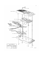
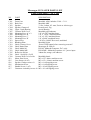
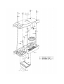
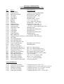
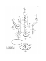
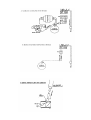
MESSENGER-II
HAND-WIND CASSETTE PLAYER
SERVICE MANUAL
GLOBAL RECORDINGS NETWORK AUSTRALIA
Locked Bag 9019
Castle Hill NSW 1765
AUSTRALIA
Email: [email protected]
Phone: +61 2 9899 2211
Fax: +61 2 9899 2602
(A.C.N 000 260 033)
Revised June 2004
MESSENGER-II HAND-WIND CASSETTE PLAYER SERVICE MANUAL
INTRODUCTION
Language Recordings has produced the Messenger-II player because of the worldwide demand from
missions and churches for a compact, reliable cassette player that is not dependent on batteries or other
costly power sources.
The purpose of this service manual is to provide the necessary technical information, parts lists and
drawings for those who will be doing in-service repairs and maintenance to these players.
The technical descriptions have been kept as simple as possible and have been prepared with the nontechnical person in mind. As well as providing this Service Manual and any necessary spare parts, we
believe in the concept that “prevention is better than cure”, and we strongly recommend that where any
“Messenger-II” players are put into use that those using them should be given careful instructions in the
basic care and maintenance of those players.
(See ‘Care of Cassette Players’ on operating instructions leaflet).
The Messenger-II Player is produced in two different ‘formats’:
a. Player Designation: LRI-03M = Plain Mabuchi i.e. Mabuchi Generator.
b. “
“
LRI-03MP = Mabuchi with Power i.e. Mabuchi Generator plus Mains Power Transformer.
TABLE OF CONTENTS
Introduction..................................................................................
Equipment & Specifications for Testing......................................
Trouble Shooting Procedure........................................................
How to Order Parts......................................................................
Messenger-II Disassembly and Servicing....................................
Messenger-II Player Assemblies - Drawing M-02.......................
Case Assembly - Parts List and Drawing M-03...........................
Generator Assembly - Parts List and Drawing M-04...................
Mechanism Assembly - Parts List and Drawing M-05................
A.C. Power Supply Assembly - Parts List and Drawing M-06....
Circuit Board Assembly - Parts List and Drawing M-07.............
Circuit Board Overlay and Schematic Diagram M-10.................
Circuit Diagram M-09..................................................................
Generator and Power Wiring Diagram.........................................
Replacing Generator leads, helpful tips........................................
Trouble-Shooting Guide...............................................................
1
2
3-5
6
7-8
9
10-11
12-13
14-15
16
17
18
19
20-21
22-23
24
EQUIPMENT & SPECIFICATIONS FOR TESTING
NECESSARY EQUIPMENT
1.Basic
a. Multimeter - With approx. 2-3v A.C. range, full deflection. e.g. A meter with a sensitivity of at least
100k/volt
b. Dummy Load - 7.5 ohms resistance and lead; or external speaker(8ohms).
c. D.C. Power Test Lead - To allow measurement of voltage & current. (Ref. Figure 1&3)
d. Test Tapes - 6.3 KHz at 15dB for Head Azimuth.
- 1 KHz at OdB for current consumption & output level.
e. 6v regulated power supply or 6v battery pack, (Fig. 1&3)
Note: Language Recordings is prepared to supply any of the above equipment to those who do not have
ready access to such.
2. Optional
a. Oscilloscope
)
b. Frequency counter
) desirable for major servicing
c. Cassette Torque Meter
) centres.
d. Signal Generator - helpful for trouble shooting of circuit board.
MEASUREMENTS & ALIGNMENT
1. Supply voltage for testing: 6v +/- 0.2v Measure the voltage across supply used for testing, with 1Khz
tape playing at full volume into dummy load (fitted to external speaker socket). If the voltage is outside
of tolerance, incorrect readings may be obtained for other tests.
2. Generator Output Voltage: Must be over 4.5v
Measure voltage across the Generator Leads at the Circuit Board while playing 1 KHz tape at full volume
into dummy load, and cranking at normal speed.
3. Playback Head Azimuth Adjustment:
(NOTE. A dot on the Name Plate Label, C120 indicates the location of a hole in the Front Case provided for
the insertion of a small screwdriver to adjust the head alignment screw).
After cleaning and demagnetising playback head, adjust the volume control to maximum and use 6.3KHz
-15dB test tape to adjust the head azimuth. Adjust output to maximum reading and when satisfied place
some contact cement on srew heads to prevent vibration moving them.
(Beware of false harmonic readings) For this reading the oscilloscope is adjusted to the following settings –
Sweep range 100-1K; Vertical gain 1/100. If an oscilloscope is unavailable a multimeter may be used.
4. Motor Speed Adjustment
Use the 1KHz -11dB tape to adjust the speed (1000-1010Hz) on the digital frequency counter, or digital
multimeter with frequency range. The adjustment is made by inserting a small screwdriver through the small
hole in the top of the drive motor and turning the adjusting screw.
5. Output Level Adjustment
Using the 1KHz -11dB tape, check the output level. It should measure about 3.6 volts peak to peak. If
necessary adjust the variable resistor VR2 to achieve the desired output. Too high a level will cause
distortion(clipping of the waveform).
If an oscilloscope is not available use the following procedure.
i.) Using an extension speaker plug and a piece of wire, fit a dummy load of 8.2 ohms across the plug. (See
Fig. 2)
ii.) Attach an AC volt meter with approximately 5-10 volts full scale deflection.
iii.) With a 1KHz -11dB tape at maximum volumethe output should be 1.3 volts RMS. (Equal to 3.6 volts
peak to peak.)
iv.) The same variable resistor adjustment VR2 can be used to obtain the right voltage reading.
6. Current consumption:190-270 mA at 6v.
Using the 1KHz -11dB tape and volume at minimum the current should be approximately 130mA, played
into an 8.2 ohm dummy load plugged into the external speaker socket. With the volume at maximum the
current should be approximately 200mA. If current is excessively high check for free movement of
mechanical parts, especially the capstan flyhweel assembly and the pinch roller.
7.Wow and Flutter: Less than 2% Play 1 KHz tape and listen for clear tone, or observe wave stability on
oscilloscope. Set up the Oscilloscope as for Azimuth Alignment and check stability at the right hand side of
the screen. Variation should not exceed 2% of screen width. Rapid fluctuation usually indicates a bent
capstan, while slower fluctuation (about 1 second duration) would indicate a worn pinch roller or other drive
component.
8.Take up Torque: 35-60 gm/cm Measured with cassette torque meter. Too much torque tends to raise
current consumption of the machine. Low torque can cause tape to wrap around capstan.
TROUBLESHOOTING PROCEDURE
INTRODUCTION
The key to efficient, effective repair is a logical approach to troubleshooting and diagnosing the
fault. The first step in any troubleshooting process is to examine carefully all the symtoms of the
fault. This investigation should guide us to a limited range of possible problem areas in the
machine. At the same time we need to eliminate areas that are functioning correctly. This enables us
to focus attention on a particular part of the machine and should help us to locate and rectify the
fault as quickly as possible.
This first step could be called the “mapping” step since the effect is to map out the problem areas
for further investigation. It is important to do a complete “mapping” of the machine before
proceeding to analyse each of the areas which may have caused the trouble. Premature assessment
of a fault, without logical and thorough investigation, can result in unnecessary removal of parts for
observation, needless replacement of good parts, tampering with adjustments that should be left
alone, and, in general, wasting a lot of valuable time.
The service manual is an essential part of the “troubleshooter’s” equipment. The information
provided in the drawings, circuit diagrams, block diagrams, parts list, etc. will help us to quickly
isolate a fault to a single area of the machine.
The novice or layman in the area of electronic repair should not be overawed by the apparent
complexity of the service manual. The manual has been prepared with the non-expert in mind and
we trust that the instructions given will be clear enough for all to follow. Regular experience in
maintenance and repair of the Messenger-II will soon help the novice to become familiar with the
parts of the machine most likely to give problems. Those who only carry out repairs on odd
occasion s or in emergencies need to take special care and be aware that hasty action or diagnosis of
the problems may lead to a lot more expense and time expended than is really necessary.
TROUBLESHOOTING PROCEDURE
The three major areas of the troubleshooting map that need to be considered when working on a
Messenger-II player are:1. The generator assembly
2. The cassette mechanism
3. The amplifier
1. The Generator Assembly
The generator assembly is probably the most straight forward mechanism within the Messenger-II
player, consisting of a drive train of gears and pulleys. However, it is subject to more wear than any
other part of the machine and usually requires a greater amount of maintenance.
2. The Cassette Mechanism
The cassette mechanism can be further broken down into smaller areas, e.g. Motor, keyboard, fast
forward mechanism etc. and each of these can be examined as separate entities. Keep in mind that a
machine takes a source of motion and processes it so as to fulfill some useful purpose. For example,
the motor provides the motion necessary to move the tape within the cassette case. It does this via a
belt, pulleys and wheels. As another example, a finger can be the source of movement. It can be
used to depress a key which then directs the motion from the motor to drive the tape forward, into
rewind, play, or if the stop key is depressed, to halt all tape motion.
3. The Amplifier
When considring the amplifie we also need to take into account the playback head, volume control,
extension speaker socket and speaker. The magnetically encoded signal on the tape produces a very
weak signal in the playback head as it passes over it. This is then amplified for the purpose of
driving the speaker.
SAMPLE PROCEDURE - 1
Symptoms of faulty player. The Messenger-II player will not operate at the correct speed when
powered by its own generator.
Preliminary Diagnosis
At first consideration you cannot help but be equally suspicious of the three main areas 1. The generator belt may have slackened with age or the generator itself may have failed.
2. The cassette mechanism could have a faulty motor, a jammed pinch roller etc.
3. The amplifier could have a fault which causes it to drain an excess amount of current from the
generator.
You need to eliminate as many areas of the “map” as you can and concentrate on the one area at
fault.
Procedure for investigation
1. Plug in an extenal 6v D.C. Source. If the player now works correctly and does not draw excessive
current, then the generator most likely is at fault. Conversely, if the player still does not work
then the generator is probably not at fault and the fault lies in one of the two other areas.
2. Check the motor by disconnecting it from the circuit board and connecting it to a seperate 6v
D.C. Power supply. If motor and mechanism operate, they are probably not at fault. If motor
speed appears to be slow, investigate current consumption of motor or replace motor.
3. Investigate current consumption of circuit board, or replace circuit board.
By following this type of procedure you are successfully reducing the areas in which you need to
look for the fault and by carrying out tests like these on each of the possible areas of failure you will
be able to locate and identify the offending component.
SAMPLE PROCEDURE - 2
Symptoms of Faulty Player: No sound.
Preliminary Diagnosis
The fault is probably in the amplifier but, before proceding to investigate this, do the following
quick checks :1. Check the cassette tape. Is it broken, jammed, or simply stopped at its end?
2. Check the cassette mechanism. In play mode is the mechanism working correctly and pulling the
tape across the playback head?
If both of the above checks show that the cassette and mechanism are satisfactory we can then
move on to investigate the amplifier chain. Note that there are 3 main sections of this:a) The speaker and extension speaker socket.
b) The amplifier section of circuit board.
c) The playback head.
(refer also to block diagram, fig. 5, p.4)
Procedure for Investigation
1. Plug an extension speaker into the extension speaker socket. This effectively by-passes the player’s own
speaker and introduces a new one. If the extension speaker works, then either the speaker in the player is
faulty, or else there is possibly a fault in the switch which is located within the extension speaker socket
or a broken wire.
2. If Procedure 1 produces no result, move on to the amplifier board. First, check this visually to see if there
are any obvious broken or loose connections. These should be resoldered. If no sound results, place
finger on both connections of the lead from the head where it 3 joins the circuit board and turn volume
up. If no noise is heard the circuit board is possibly at fault and should be replaced.
3. If Procedure 2 produces noise, proceed to check the playback head and its connections. Use a mutimeter
to check the wires from the head to the amplifier board. if the connections are satisfactory the head
should be replaced.
Messenger-II PLAYER PARTS LIST
HOW TO ORDER PARTS
1.INTRODUCTION
a. SERIAL NUMBER: Example of a serial No. 09-89 M DCEC 00022
The serial number, as found both inside and outside the player, is composed of three main parts.
i. Date of manufacture ’09-89' Letter- ‘M’ Designates what generator type is used, and whether
A.C. power supply is included, e.g. M= Mabuchi, MP= Mabuchi with A.C. Power.
ii. Batch Letters - These designate the revision batches of the main assemblies in the machine.
These are essential for supply of correct repalcement parts. They are stamped on each assembly as
indicated on the parts drawings and are listed in the serial number in the following order Case Assembly - Generator Assembly - Mechanism Assembly - Circuit Board Assembly.
iii. Machine No. - Identifies the particular machine.
e.g. Model Letters
Batch Letters
Machine No.
M
DCEC
00022
b.PARTS NUMBERS:
Example of a Part No. 5G217
These consist of i. A prefix letter ’5G’ which indicates which assembly the part is from, and thereby on which
drawing it is shown.
ii. A single digit numeral to indicate major part revisions or alternative types. These are listed
underneath each other in the parts list, and must be determined when ordering parts. An ‘x’
indicates alternative types of the part, and that appropriate type no. must be selected from the parts
list when ordering. (The ‘5’ is a computer prefix)
e.g. Gx17 refers to G117 or G217 in parts list.
iii. A two digit numeral to identify the particular part in the assembly.
Assembly Letter
Type No.
Part No.
e.g. Part No. B104
B
1
04
2. HOW TO ORDER PARTS.
Please identify the part from Parts Drawings, and write both its Part No. (including appropriate
type), and Name plus Quantity.
Also, please include complete Serial Number/s of the player/s for which the parts are required. If the
parts are for spares for a a quantity of players, then the most common Model Letters and Batch
Letters would be sufficient.
Sample Order
QUANTITY
PART NO.
NAME
SERIAL NO.
5
05-G104
Gen. Belt
MP-DCEC-01548
If possible, please try to explain what is the fault in worn parts and what may have caused them to
fail. Also describe the symptoms of the fault and the in-service age of the player. This will greatly
help us to develop a better player for the mutual benefit of all users of these players.
MESSENGER-II DISASSEMBLY AND SERVICING
Please refer to Drg. M-02
To Open Case (See also drg. M-03)
a) Unscrew the Crank arm Assembly G150 by raising the handle and turning it anticlockwise (opposite
direction to the arrow). This may require a sharp tap on the winding arm to begin the unwinding.
b) Remove 5 screws (4 Case Screws C114 and one Handle Screw C115) in back of case. Carefully pull the
two halves fo the case apart while keeping them parallel to each other. There may be some resistance at
first, until the Crank Shaft G109 is pulled through the Upper Crank Bearing C106, but pull the halves
apart carefully as the generator wires may be broken. It is now possible to unplug socket connector G141
on Mabuchi player without power, and socket connector p112 on Mabuchi player with power, from the
circuit board and so separate the two halves of the player case. Note: Be careful not to pull on the wires.
Grasp the socket connector between thumb and forefinger from above and gently ease out with the help
of a small screw driver.
2.To Remove Mechanism 05-M200 and Circuit Board Assemblies.
( See also drg. M-03, M-05)
a) Buttons (keys) M102, M103, M104, M105 must be in OFF position.
b) Desolder the two wires from the Speaker C103, and unplug PIN connector.
c) Unscrew the Spacer Post C112, Motor Plate Screw S12 and the Mechanism Screw C116 located near the
Clutch Assembly on the mechanism, then lift the mechanism from the Front Case C101.
3. Circuit Board Assembly B600. (See also Drg. M-97)
a. To Remove and Disassemle
i. Remove Circuit Board Screw M106 and Washer M107. Loosen the Side Plate Screws M108 and then
move the assembly sideways from the mechanism.
ii. If the circuit board is to be replaced, desolder all wires from the circuit board, noting their colour and
position on the board. Remove the two D.C. Socket Screws S02 and the Dress Ring B207 from the
External speaker Socket B206 and them remove the Side Plate B208. Remove the Volume Control Screw
S01 and Wheel B202.
b. To Reassemble and Replace
i. Replace Volume Control Wheel B202 and Screw S01
ii. Attach Side Plate B208 with Screws S02 and Dress Ring B207.
iii. Position the Circuit Board Assembly correctly on the mechanism, by pushing the slots of the Side Plate
firmly against the Side Plate Screws M108 before tightening them. Then replace Circuit Board Screw
M106 and Washer M107.
4. Servicing the Mechanism M100 (See also drg. M-05)
a) With the mechanism removed from the case, all pars of it are easily accessible for adjustment and
replacement of parts.
b) Before removing any part, note it’s position and method of retention. Also observe other associated parts
which may be disturbed during removal, such as springs and washers. Very carefully remove the small
components, such as ‘E’ clips, which may be easily lost.
c) If the Flywheel is removed, care should be taken that its capstan shaft is not knocked in any way
during handling. Any damage to the capstan shaft would cause the player to produce a rapidly
wavering sound. After replacing the Flywheel, or removing the Flywheel Retainer Plate, its endplay should be checked. This should be 0.005" - 0.010" (0.13 - 0.25 mm). If this is incorrect, it
should be adjusted as follows:i. Make certain the 3 screws securing the Flywheel Retainer Plate are tight. N.B. Do not
overtighten any screws on the mechanism.
ii. Using a screwdriver, adjust the End Thrust Bearing in the Retainer Plate until there is a
slight gap between the bearing and the end of the shaft of the Flywheel.
iii.Remove the Drive Belt M120 from the Motor Pulley. Move the Flywheel up and down to
feel the end-play, while slowly screwing the Thrust Bearing in, until the end-play just
disappears. Then unscrew the Bearing 1 turn and check that the Flywheel has the correct
amount of end-play and spins freely.
iv. Replace the drive belt, and seal the Thrust Bearing in place with contact cement.
d) To replace the Playback Head M114, unsolder the wires, remove only the screw nearest the pinch
roller. Then move the Head sideways out from under the other screw. If the Playback Head is
replaced or disturbed, its azimuth angle will need to be adjusted to ensure correct playback of all
frequencies. This is achieved by adjusting the spring loaded mounting screw while playing a 6.3
KHz at -15dB alignment tape, and adjusting for maximum signal level (please refer to testing
procedures). If a special alignment tape is not available, a good music passage on a commercially
produced tape may do. Listen for sharpness of high frequency parts of the music. Finally, seal the
alignment screw which contact cement.
Azimuth Alignment tapes may be obtained from Language Recordings Inc., Australia.
e) Before reassembling the machine, check that the Leaf Switch operates properly when the Play
Button (Key) is depressed. Check that all moving parts of the mechanism are operating
satisfactorily, and check that all springs & ‘E’ clips are in place and that screws are not loose.
N.B. Do not over-tighten any screws on the mechanism.
5. Generator Assembly G100
Servicing of the Generator Assembly G100 other than replacing the Belt, is best carried out by
replacing any faulty sub-assembly with a new unit (see parts list). Individual parts may be replaced
if it is determined that only one part is at fault.
6. Closing Case
When closing the case check carefully that the lead from the Generator
to the circuit board is not touching any moving parts.
7. Re-checking Player Performance.
After repairs or adjustments are completed, re-check the relevant specifications of the player using
the test procedures listed under “Equipment & Specifications for Testing”. Remove all dirt and dust
from the player before closing the case and clean head, capstan and pinch roller as described in the
Operating Instructions.
Messenger-II PLAYER PARTS LIST
CASE ASSEMBLY - No. C100
NO.
PART
DESCRIPTION
C101
C102
C103
C104
C106
C107
C108
C109
C110
C111
C112
C118
C119
C120
C121
C123
C125
C126
C129
S12
S15
S16
S16
S17
S17
Front Case
Back Case
Speaker
Speaker Clamps x2
Upper Crank Bearing
Cassette Well Cover
Mounting Post ‘A’ x 2
Mounting Post ‘B’
Mounting Post ‘C’
Mounting Post ‘D’
Spacer Post
Blanking Plate
Label-Cassette Cover
Label-Name Plate
Label-Model M
Label-Model MP
Reflective Sticker
Label - Serial No. (2 off)
Cassette Well Cover Locks
Motor Post Screw
Case Screws (4 off)
Speaker Clamps screws x2
Mechanism Screw
Handle Screw (1 off)
Generator Assembly screws x2
Moulded ABS, includes C108 - C111.
Moulded ABS.
3" dia, 8 ohms, 0.5 watt, Ferrite or Alnico type.
Pressed steel, 22g
Acetal Bearing
Moulded polycarbonate.
1/4" x 0.925" machine brass.
1/4" x 1.850" machined brass.
1/4" x 2.283" machined brass.
1/4" x2.600" machined brass.
1/4"AF x 0.0948" Hex-steel, machined
Moulded Nylon
“Press STOP button before removing cassette”/
Messenger-II: LRI-02
LRI-02- Mabuchi Generator, D.C. only.
LRI-03MP - Mabuchi Generator A.C. power input.
24mm dia, orange, self adhesive.
Moulded plastic
M3 x 0.5 x 6mm, machine screw
M3 x 0.5 x 16mm, machine screw
M3 x 6 self tapping screw
M3 x 6 self tapping screw
M3 x 10 self tapping screw
M3 x 10 self tapping screw
Messenger-II PARTS LIST
GENERATOR ASSEMBLIES - NO. G100
NO.
G102
G104
G106
G107
G108
G109
G111
G112
G117
G118
G120
G121
G122
G123
G124
G125
G126
G132
G141
G143
G144
G145
G146
G227
P106
P114
S06
S12
S14
W03
W03
W06
W07
W08
W09
W10
PART
DESCRIPTION
Pulley Wheel
Moulded acetal
Generator Belt
2.2mm sq. section, polyurethane.
Pulley Wheel Shaft
Machined steel, 5mm dia.
Gear Plate
Pressed Steel, galv., 20g
Gear Wheel
Moulded Nylon
Crank Shaft
Machined Steel, 1/4 dai.
Roll Pin
1/16" x 1/2" steel pin.
Split Pin
1.6 x 12mm steel, split pin
Generator
Mabuchi RF—370C 15370
Generator Plate
Pressed steel, galv, 20g
Generator Pulley
12mm dia. x 7mm wide (M)
Crank Arm Pin
3/32" dia. x 12mm, tubular alum. rivet.
Crank Drive Stud
Machined steel
Crank Arm
Moulded Glass filled nylon
Crank Knob
Moulded nylon
Crank Hub
Moulded glass filled nylon
Crank Knob Pin
Machined steel
Pulley Shaft Nut
1/8" B.S.W., hex, steel.
Generator Socket Connector Utilux H9540-3 KK connector.
Gear Plate
Gear Adjusting Plate
Gear Adj. Plate Rivet
Gear Adj. Plate Root Nut
Lower Crank Bearing
Moulded acetal .250" I.D.
Cable Tie 150mm
Moulded plastic
Terminal Clip (large)
Generator Plate Screws x 2
M2.6 x 4 Taptite Screws
Gear Adjusting Plate Screw.
M3 x 0.5 x 6mm machine screw
Generator Screws x 2
M3 x 0.5 x 3.5mm machine screws
Generator Screw Washer
M3 internal shake proof washer
Pulley Shaft Washer
M3 internal shakeproof (star) washer
Gear Adj. Plate Washer
1/8 x 3/8 washer
Crank Thrust Washer
5/32” x 3/8” x 21g flat washer
Pulley Wheel Washer
M10 x 5 x 0.5 steel washer
Crank Bearing Washer
1/4" x 1/2" x 24g flat washer
Lower crank Bearing clamp
Pressed spring steel
SUB ASSEMBLIES
G110
G116
G138
G142
G150
Crank Shaft Assembly
Generator Lead Assembly
Generator Assembly
Gear Plate Assembly
Crank Arm Assembly
Comprises part nos. G109, G111
Comprises twin core wire, plus G141, 2 x P114
Comprises part nos. G117, G120,G116,P106
Comprises part nos. G143, G146
Comprises Part Nos. G121—G126, W07
MECHANISM ASSEMBLY - No. M200
NO.
PART
DESCRIPTION
5E01
5E02
5E02
5E03
5E03
5M108
5M110
5M114
5M115
5M117
5M120
5M122
5M127
5M139
5M143
5M145
5M149
5M153
5M154
5M161
5M162
5M166
5M168
5M170
5M172
5M174
5M174
5M178
5M193
5M194
5M195
5M203
5M208
5M238
5P106
5S03
5S08
5S08
5S10
5S12
5S12
5S22
5S23
5S24
5W01
5W01
5W03
Reel cap circlip x 2
Brake plate guide pin circlip x 3
Pinch Roller frame post circlip
Clutch swivil pin circlip
Head base guide circlip x 3
Motor screw sleeve (x3)
Drive motor assembly
Playback head
Pinch roller assembly
Capstan flywheel assembly
Drive belt
Leaf switch (x2)
Flywheel assembly
Pinch roller frame spring
Head base assembly
Head base spring
Azimuth alignment spring
Latch plate
Latch plate spring
Flywheel support plate
Flywheel thrust bearing
Brake plate assembly
Brake plate spring
Rewind motor assembly
Rewind motor plate
Rewind motor plate spring
Take-up Clutch spring
Cassette tension spring
Reel stand spring
Reel stand (1 piece) (x2)
Reel stand rubber (x2)
Motor Cushion (x3)
Deck Plate Assembly
Take-up clutch assembly
Cable Tie 100mm
Leaf switch screw (x2)
Button frame screw (x3)
Rewind Motor Plate screw (x2)
Playback head alignment screw
Circuit board screw
Flywheel supt. post screw (x3)
Side Plate screw (x2)
Drive Motor screw (x3)
Rewind motor screws (x2)
Reel Stand Washer
Flywheel Assembly Washer
Circuit board washer
M1.5
M2
M2
M3
M3
Machined brass
75 x 1.2mm square section polyurethane
M2x5 taptite screw
M2.6x6 taptite screw
M2.6x6 taptite screw
M2x6 Philips machine screw
M3x6 Philips machine screw
M3x6 Philips machine screw
M3x6 Philips taptite screw
M2.7x6 machine screw
M3x3.5 Philips machine screw
Polyslider M2.2x4x0.3
Polyslider M2.2x4x0.3
M3 internal shakeproof washer
SUB-ASSEMBLIES
5M110 Drive Motor Assembly
5M109 Drive motor
5M111 Drive motor pulley
5P106 Cable Tie 150mm
5M115 Pinch Roller Assembly
5M136 Pinch roller
5M137 Pinch roller axle
5M138 Pinch roller frame
5M130 Button frame assembly
5E02
Button shaft circlip
5M102 Stop button (red)
5M103 Play button (green)
5M104 Forward button (yellow)
5M105 Rewind button (blue)
5M131 Button frame
5M132 Button frame shaft
5M135 Button blade (x4)
5M175 Button spring (f) (x2)
5M176 Button spring (g) (x2)
Mabuchi EG-510D-6F2, 6v, 2400rpm
M130OD x 6.5 x 2.5 bore
M11.2 x 2.5
M2 E-clip
Pressed steel
Pressed steel
5M143 Head Base Assembly
5M144 Head Base
5M146 Replay head stud
5M150 Azimuth alignment stud
5M151 Cable Tie stud
5M213 Pinch Roller Frame post
5M157 Capstan Bearing Assembly
5M158 Capstan bearing housing
5M159 Capstan bearings (x2)
5M166 Brake Plate Assembly
5M167 Brake plate
5M169 Brake Plate guide pin
5M170 Rewind Motor Assembly
5G117 Generator/Rewind motor
5M186 Rewind Motor Pulley
5P106
Cable Tie 150mm
5M208 Deck Plate Assembly
5M155 Latch plate posts (x2)
5M157 Capstan Bearing Assembly
5M163 Flywheel support post (x3)
5M169 Brake plate guide pins (x3)
5M192 Reel Shaft Assembly (x2)
5M209 Deck Plate
5M210 Cassette Support stud (x2)
5M211 Cassette location pin (x2)
5M212 Head Bases Guide Pin (x3)
5M214 Cct board support post
5M256 Clutch swivil pin
Mabuchi RF-370-15370
MESSENGER PLAYER PARTS LIST
A.C. POWER SUPPLY ASSEMBLY NO. P100
No.
5P101
5P102
5P103
5P104
5P107
5P108
5P109
5P110
5P112
5P113
5P114
PART
Transformer
A.C. Socket
A.C. Socket back cover
Selector plate
Cable Tie x3
A.C. Power cord
Loom sleeve
Cable insulation sleeve
Pin connector
Terminal clip (small)
Terminal clip (large)
DESCRIPTION
110/24v, 60Hz: 7v x 2, 250mA
Hosiden type No. HSC0438
Hosiden type No. HSC0438-03-010
Moulded glass filled nylon
M8 O.D. X 20mm PVC tubing
Cable tie with screw hole
3303-108 Adilam
3400-113 Adilam
3400-111 Adilam
CIRCUIT BOARD ASSEMBLIES B601 & B602
5B601
Circuit Board Assembly (plain)
5B600
Circuit Board ex supplier
5B202
Volume Control wheel
5B208
Side plate
5B213
Pin connector (3 pin)
5B214
Polarised Header
5S01
Volume Control screw M1.7 x 5 machine screw
5B602
Circuit Board Assembly (power)
5B601
Circuit Board Assembly (plain)
5B218
Pin connector (4 pin)
5B215
Voltage Regulator
5B216
Regulator diode
5B217
Capacitor 1000uF 16V
5B219 Side Plate Assembly (plain)
5B601
Cct brd assmy plain
5B207
Dress ring
5B208
Side Plate
5B220 Side Plate Assembly (power)
5B602 Side Plate Assembly power
5B207 Dress Ring
5B208 Side Plate
Note: Power and non-power versions are identical, except that non-power models may have
components IC2, D3-D5,C19 omitted.
MESSENGER PLAYER – TROUBLE-SHOOTING GUIDE
The following is an outline of some possible causes of faults that may occur in the player.
SYMPTOM
POSSIBLE CAUSE
1. No Action – when
* No power to player – (not switched on at power source. Play button not
operating from external power depressed, batteries flat, broken power lead.)
* Switches dirty
* Motor belt worn or broken.
* Motor faulty
2. No Action – when
operating by hand.
* Not cranking fast enough.
* Generator belt worn or stretched.
* Generator mechanism worn out.
* Faulty generator.
3. No sound
* Tape finished, jammed or broken.
* Wiring joints faulty.
* Volume control not turned up, or faulty.
* Speaker faulty
* Circuit board faulty
* Head faulty
4. Sound not clear
* Tape worn or old
* Head dirty or worn
* Head alignment incorrect
* Low power supply
* Capstan bent
5. Speed slow or irregular
* Cassette faulty or jammed
* Generator or motor belt slipping
* Take-up cluth worn out
* Motor faulty
* Capstan bent
* Faulty pinch roller assembly
6. Speed too fast
* High supply voltage
* Pinch Roller not contacting capstan
* Motor faulty
7. Tape winds around
capstan shaft
* Dirty capstan and pinch roller
* Faulty or mal-adjusted take-up clutch
* Take-up spindle seized, bent or faulty
* Cassette tape not running freely in housing.
8. Grinding noise when
cranking
* Worn gears and/or bearings.
* Generator mechanism parts clashing.
9. No sound from external
speaker
* Speaker or wiring faulty.
* Speaker socket faulty.
10. Rewind faulty
* Rewind motor pully not contacting rubber ring of reel stand.
* Faulty or dirty switch.
* Faulty rewind motor or wiring.