1
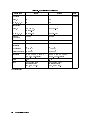
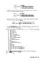
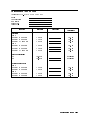
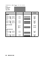
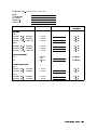
Operation and Service Manual
Agilent 87511A/B S-PARAMETER TEST SET
SERIAL NUMBERS
This manual applies directly to instruments with serial
number prex 3026J (87511A) and 3042J (87511B).
For additional important information about serial numbers, read
\INSTRUMENT COVERED BY MANUAL" in Chapter 1.
Agilent Part No. 87511-90010
Printed in JAPAN
July 2001
Third Edition
Notice
The information contained in this document is subject to change without notice.
This document contains proprietary information which is protected by copyright. All rights
are reserved. No part of this document may be photocopied, reproduced, or translated to
another language without the prior written consent of the Agilent Technologies.
Agilent Technologies Japan, Ltd.
Component Test PGU-Kobe
1-3-2, Murotani, Nishi-ku, Kobe-shi,
Hyogo, 651-2241 Japan
c Copyright 1990, 2000, 2001 Agilent Technologies Japan, Ltd.
Manual Printing History
The manual printing date and part number indicate its current edition. The printing
date changes when a new edition is printed. (Minor corrections and updates which are
incorporated at reprint do not cause the date to change.) The manual part number changes
when extensive technical changes are incorporated.
October 1990
First Edition (part number: 87511-90000)
February 2000
Second Edition (part number: 87511-90000)
July 2001
Third Edition (part number: 87511-90010)
::::::::::::::::::::::::::::::::::::
:::::::::::::::::::::::::::::::::
::::::::::::::::::::::::::::::::::::::
iii
Safety Summary
The following general safety precautions must be observed during all phases of operation,
service, and repair of this instrument. Failure to comply with these precautions or with
specic WARNINGS given elsewhere in this manual violates safety standards of design,
manufacture, and intended use of the instrument.
The Agilent Technologies assumes no liability for the customer's failure to comply with these
requirements.
DO NOT Operate In An Explosive Atmosphere
Do not operate the instrument in the presence of ammable gasses or fumes. Operation of any
electrical instrument in such an environment constitutes a safety hazard.
Keep Away From Live Circuits
Operating personnel must not remove the instrument covers. Component replacement and
internal adjustments must be made by qualied maintenance personnel. Do not replace
components with the power cable connected. Under certain conditions, dangerous voltages
may exist even with the power cable removed. To avoid injuries, always disconnect power and
discharge circuits before touching them.
DO NOT Service Or Adjust Alone
Do not attempt internal service or adjustment unless another person, capable of rendering
rst aid and resuscitation, is present.
DO NOT Substitute Parts Or Modify Instrument
Because of the danger of introducing additional hazards, do not substitute parts or
perform unauthorized modications to the instrument. Return the instrument to a Agilent
Technologies Sales and Service Oce for service and repair to ensure the safety features are
maintained.
Dangerous Procedure Warnings
Warnings, such as the example below, precede potentially dangerous procedures throughout
this manual. Instructions contained in the warnings must be followed.
Warning
Dangerous voltages, capable of causing death, are present in this instrument.
Use extreme caution when handling, testing, and adjusting this instrument.
iv
Typeface Conventions
Bold
Italics
Computer
4HARDKEYS5
NNNNNNNNNNNNNNNNNNNNNNNNNN
SOFTKEYS
Boldface type is used when a term is dened. For example: icons are
symbols.
Italic type is used for emphasis and for titles of manuals and other
publications.
Italic type is also used for keyboard entries when a name or a variable
must be typed in place of the words in italics. For example: copy
lename means to type the word copy, to type a space, and then to
type the name of a le such as file1.
Computer font is used for on-screen prompts and messages.
Labeled keys on the instrument front panel are enclosed in 4 5.
Softkeys located to the right of the CRT are enclosed in .
NNNNN
Certification
Agilent Technologies certies that this product met its published specications at the time
of shipment from the factory. Agilent Technologies further certies that its calibration
measurements are traceable to the United States National Institute for Standards and
Technology, to the extent allowed by the Institution's calibration facility, or to the calibration
facilities of other International Standards Organization members.
Warranty
This Agilent Technologies instrument product is warranted against defects in material and
workmanship for a period of one year from the date of shipment, except that in the case of
certain components listed in Chapter 1 of this manual, the warranty shall be for the specied
period. During the warranty period, Agilent Technologies will, at its option, either repair or
replace products which prove to be defective.
For warranty service or repair, this product must be returned to a service facility designated
by Agilent Technologies. Buyer shall prepay shipping charges to Agilent Technologies and
Agilent Technologies shall pay shipping charges to return the product to Buyer. However,
Buyer shall pay all shipping charges, duties, and taxes for products returned to Agilent
Technologies from another country.
Agilent Technologies warrants that its software and rmware designated by Agilent
Technologies for use with an instrument will execute its programming instruction when
property installed on that instrument. Agilent Technologies does not warrant that the
operation of the instrument, or software, or rmware will be uninterrupted or error free.
v
Limitation Of Warranty
The foregoing warranty shall not apply to defects resulting from improper or adequate
maintenance by Buyer, Buyer-supplied software or interfacing, unauthorized modication or
misuse, operation outside of the environment specications for the product, or improper site
preparation or maintenance.
No other warranty is expressed or implied. Agilent Technologies specically disclaims the
implied warranties of merchantability and tness for a particular purpose.
Exclusive Remedies
The remedies provided herein are buyer's sole and exclusive remedies. Agilent Technologies
shall not be liable for any direct, indirect, special, incidental, or consequential damages, whether
based on contract, tort, or any other legal theory.
Assistance
Product maintenance agreements and other customer assistance agreements are available for
Agilent Technologies products.
For any assistance, contact your nearest Agilent Technologies Sales and Service Oce.
Address are provided at the back of this manual.
vi
Safety Symbols
General denitions of safety symbols used on equipment or in manuals.
Instruction manual symbol: the product will be marked with this symbol
when it is necessary for the user to refer to the instruction manual in order to
protect against damage to the instrument.
Indicates dangerous voltage (terminals fed from the interior by voltage
exceeding 1000 volts must be so marked).
Protective conductor terminal. For protection against electrical shock in case
of a fault. Used with wiring terminals to indicate the terminal which must be
connected to ground before operating equipment.
Low-noise or noiseless, clean ground (earth) terminal. Used for a signal
common, as well as providing protection against electrical shock in case of
fault. A terminal marked with this symbol must be connected to ground
in the manner described in the installation (Operation) manual, and before
operating the equipment.
Frame or chassis terminal. A connection to the frame (chassis) of the
equipment which normally includes all exposed metal structures.
Alternating current (power line).
Direct current (power line).
Alternating or direct current (power line).
Warning denotes a hazard. It calls attention to a procedure, practice,
condition or the like, which, if not correctly performed or adhered to, could
result in injury or death to personnel.
Caution sign denotes a hazard. It calls attention to a procedure, practice,
condition or the like, which, if not correctly performed or adhered to, could
result in damage to or destruction of part or all of the product.
Note denotes important information. It calls attention to a procedure,
practice, condition or the like, which is essential to highlight.
vii
1
General Information
INTRODUCTION
The purpose of this manual is to enable you to use your 87511A (including Option 001) or
87511B S-parameter test set eciently and condently. This manual contains both general
and specic information. When information applies to both the 87511A (the 50
test set,
including Option 001) and the 87511B (the 75
test set) the name 87511A/B is used. To use
the 87511A/B to perform a specic function (without reading the entire manual), follow the
directions in \USING THE 87511A/B".
This chapter
(1) outlines how to begin using the 87511A/B as quickly as possible,
(2) describes what instrument are covered by this manual,
(3) describes the test set itself,
(4) mentions operating precautions, safety considerations and warranty restrictions,
(5) lists the additional equipment required, and
(6) denes and lists the required instrument specications.
USING THE 87511A/B
The 87511A/B has been designed to operate specically with the 8751A network analyzer.
To install the instrument, turn to Chapter 2.
To oprate the 87511A/B, see the Chapter 3.
To verify that the instrument meets its published specications, turn to Chapter 4.
to order replaceable parts of the 87511A/B, to turn to Chapter 6.
To troubleshoot the 87511A/B, turn to Chapter 7.
General Information
1-1
INSTRUMENTS COVERED BY MANUAL
You will nd a two-part serial number on the rear panel of the test set. The rst four digits
and the letter are the serial number prex. The last ve digits are the sequential sux
which is unique to each test set. The contents of this manual apply directly to test sets with
the same serial number prex as the one(s) on the title page under the heading SERIAL
NUMBERS.
If the serial prex of your test set is not listed on the title page, your instrument diers from
those documented in this manual. The dierences are documented in the yellow manual
changes supplement supplied with the manual.
To keep this manual as current and accurate as possible, Agilent Technologies recommends
that you periodically request the latest manual changes supplement, as it may contain
replacement information as well as change information. The supplement for this manual is
keyed to the manual's print date and part number (on the title page) and is available on
request from Agilent Technologies.
This manual is also available on microche form (the part number appears on the title page).
With the manual (in 4 2 6 inch microlm transparency format) you will also receive the latest
manual changes supplement.
DESCRIPTION AND OPERATING CHARACTERISTICS OF THE
INSTRUMENT
The 87511A/B S-parameter test set has been designed to operate with the 8751A network
analyzer. The 87511A/B provides a convenient means of measuring the reection and
transmission coecients (scattering parameters) of one-port or two-port devices operating
within the frequency range of 100 kHz to 500 MHz.
Table 1-2 lists the operating specications and characteristics of the 87511A/B. The test set is
shown on the cover of this manual and shown in Figure 3-1.
1-2
General Information
OPTIONS
Option 001, 50
Type-N Test Port (87511A only)
Option 907, Front Handle Kit (Agilent Part Number 5062-3988)
Option 908, Rack Mount Kit (Agilent Part Number 5062-3974)
This option is a rack mount kit containing a pair of anges and the necessary hardware to
mount the instrument, with handles detached, in an equipment rack with 482.6 mm (19
inches) horizontal spacing.
Option 909, Rack Mount Flange and Handle Kit (Agilent Part Number 5062-3975)
This option is a rack mount kit containing a pair of anges and the necessary hardware to
mount the instrument with handles attached in an equipment rack with 482.6 mm (19 inches)
horizontal spacing.)
Option 910, Extra Operation Manual
This option is an extra OPERATION AND SERVICE MANUAL. (Agilent Part Number
87511-90000)
General Information
1-3
Figure 1-1. 87511A/B S-Parameter Test Set with Accessories Supplied
ACCESSORIES
Accessories Supplied
Figure 1-1 shows the 87511A/B with the accessories supplied:
Interconnect Cable
RF Connecting Cables
Accessories Available
Calibration and Accessory Kits
The calibration kits listed in Table 1-1 contain the components required to characterize the
systematic errors of various measurement systems. The calibration kits also contain precision
adapters.
The accessory kits listed contain the components generally required to measure devices with
the types of connectors indicated. Additional information is included in the 8751A manual.
1-4
General Information
Table 1-1. Accessories Available
Connector Type Calibration Kit Accessory Kit
7 mm
Type-N 50
Type-N 75
BNC 50
1
85031B
85032B
85036B
11853A
1
11854A
1
use with 85032B type-N 50
calibration kit
Cable Sets
Use the 11857D 7 mm test port return cable set to extend the test ports of the 87511A. Use
the 11851B 50
type-N cable to extend the test port of the 87511A with Option 001. Use the
11857B 75
type-N test port return cable set to extend the test port of the 87511B.
OPERATING AND SAFETY PRECAUTIONS
Operating
You need observe only normal precautions in handling and operating the 87511A/B. Do not
exceed its operating level input of +23 dBm or any DC voltage.
Caution
Electrostatic discharge (ESD) can damage the highly sensitive microcircuits
in the 87511A/B test sets. ESD damage is most likely to occur as the test
sets are connected or disconnected. Protect them by wearing a grounding
strap that provides a path to ground of high resistance. Alternatively, ground
yourself by touching the outer shell of any grounded instrument chassis before
touching the test port connectors.
Never touch the center contacts of the connectors.
Use a work station equipped with an anti-static surface.
Service
The voltages in this test set do not warrant more than normal caution for operator safety.
Nevertheless, service should be performed by qualied personnel.
General Information
1-5
RECOMMENDED TEST EQUIPMENT
Table 4-1 lists equipment and accessories required for testing, and repairing the 87511A/B.
The table notes which items are required to verify the performance of the test set and which
are required to troubleshoot it. Other equipment may be substituted if its specications meet
or exceed the specications listed in the critical specications column.
SPECIFICATIONS
Definitions
The specications listed in Table 1-2 range from those guaranteed by Agilent Technologies
to those typical of most 87511A/B instruments but are not guaranteed. Codes in the far
right column of Table 1-2 reference a specication denition listed below. These denitions
are intended to clarify the extent to which Agilent Technologies supports the specied
performance of the 87511A/B.
S
This performance parameter is eld veriable using performance tests documented in
the Chapter 4.
T
Typical but non-warranted performance characteristics intended to provide information
useful in applying the instrument. Typical characteristics are representative of most
instruments, though not necessarily tested in each unit and not eld tested.
1-6
General Information
These specications describe the analyzer's performance over the temperature range of 2365
C.
Table 1-2. Specifications
Parameter
Frequency
Range
Directivity :
Port 1,2
1
87511A
87511B
100 kHz to 500 MHz
100 kHz to 500 MHz
30 dB, 100 kHz to 300 kHz
40 dB, 300 kHz to 200 MHz
35 dB, 200 MHz to 500 MHz
(37 dB, 300 kHz to 200 MHz)
30 dB, 100 kHz to 300 kHz
33 dB, 300 kHz to 500 MHz
Code
S
2
Port Match :
R, A, B
RF IN
Switch
Repeatability
Source Match
T
1
1
Frequency
Response :
Transmission
Tracking
Magnitude
Phase
20 dB
20 dB
60.03 dB
20 dB
20 dB
60.03 dB
15 dB, 100 kHz to 300 kHz
20 dB, 300 kHz to 500 MHz
15 dB, 100 kHz to 300 kHz
20 dB, 300 kHz to 500 MHz
S
T
1
3
4
Reection
Tracking
Magnitude
Phase
4
3
61 dB
610, 100 kHz to 300 kHz
65 , 300 kHz to 500 MHz
61 dB
615 , 100 kHz to 300 kHz
65 , 300 kHz to 500 MHz
61 dB
615, 100 kHz to 300 kHz
65 , 300 kHz to 1 MHz
65 , 1 MHz to 500 MHz
61 dB
620 , 100 kHz to 300 kHz
610 , 300 kHz to 1 MHz
65 , 1 MHz to 500 MHz
Insertion Loss:
RF IN to Port 1,2 13 dB
RF IN to R, A, B 19 dB
Isolation between 110 dB
Port 1 and 2
1
2
3
4
Nominal
19 dB
31 dB
100 dB
T
can be greatly improved with 8751A accuracy enhancement techniques
Option 001 only
Deviation from mean value
Deviation from linear phase
General Information
1-7
Table 1-3. Specifications (continued)
Parameter
Impedance:
Port 1, 2
RF IN, R, A, B
Connectors:
Port 1, 2
RF IN R, A, B
Maximum
Input Level
Damage Level
Operating
Conditions:
Temperature
Relative Humidity
Dimensions
Weight
Power
1
87511A
Code
Nominal
50
50
75
50
7 mm (50 )
50
type-N(f)
50
type-N(f)
+20 dBm
75
Type-N(f)
+23 dBm
+23 dBm
0 C to 55 C
95% at 40 C
432 mm 2 90 mm 2 495 mm
(17 2 3.5 2 19.5 inches)
5.7 kg
+22 Vdc from 8751A
via interface cable
(22 V, 20 mA typ.)
0 C to 55 C
95% at 40C
432 mm 2 90 mm 2 495 mm
(17 2 3.5 2 19.5 inches)
5.7 kg
+22 Vdc from 8751A
via interface cable
(22 V, 20 mA typ.)
1
Option 001 only
1-8
87511B
General Information
50
type-N(f)
+20 dBm
2
Installation
INTRODUCTION
This chapter explains how to install the 87511A/B test set. The topics covered include initial
inspection, environment considerations, positioning and connecting the test set for use, and
packaging the instrument.
INITIAL INSPECTION
Inspect the shipping container (including cushioning material) for damage. If it is damaged,
keep it until you have checked the contents for completeness. The contents are listed in
Table 2-1.
In addition, check the test set mechanically and electrically. If the test set and shipping
container are undamaged, performing the Directivity performance test in Chapter 4 should
suce for incoming inspection. If the test set does not pass the performance test, refer to the
troubleshooting procedures in Chapter 7.
If the shipping container is damaged, perform all electrical performance tests in Chapter 4. If
the test set fails the electrical tests, or is damaged, defective, or incomplete, keep the shipping
materials and notify both the carrier and the nearest Agilent Technologies oce. The Agilent
Technologies oce will arrange for repair or replacement of the test set without waiting for
settlement of the claim.
Table 2-1. Contents of the 87511A/B
Component
Interconnect Cable
RF Connecting Cables
Operation and Service Manual
1
1
Agilent Part Number
87511A
08503-60051
8120-4782
87511-90000
87511B
08503-60051
8120-4782
87511-90000
Consists of four cables
Installation
2-1
ENVIRONMENTAL CONSIDERATIONS
Operating and Storage
The 87511A/B should be operated in temperatures between 0 C and +55 C with relative
humidity between 5% and 95% at 40C (non-condensing). It may be operated at altitudes up
to 4,500 meters (15,000) feet.
The 87511A/B may be stored in temperatures from 040 C to +70 C, with relative humidity
up to 90% at +65 C (non-condensing) and at altitudes up to 15,240 meters (50,000 feet).
PREPARATION FOR USE
Positioning the Test Set
Typically the 87511A/B is placed under the 8751A network analyzer whether it is
rack-mounted or used on a bench.
To install the 87511A/B for use on a bench, place it under or next to the 8751A. Use an
anti-static work surface to lessen the chance of ESD damage.
Connecting the Test Set
Mating Connectors
Ports 1 and 2 of the 87511A are precision 7 mm connectors and mate with precision 7
mm connectors. Ports 1 and 2 of the 87511A Option 001 are precision 50
type-N female
connector and mate with precision 50
male connectors. Ports 1 and 2 of the 87511B are
precision 75
type-N female connector and mate with precision 75
male connectors.
Caution
Do not mate type-N 50
connectors to type-N 75
connectors or damage may
result.
The RF IN, R, A and B ports of the 87511A/B are precision 50
type-N female connectors
which mate with the corresponding precision type-N male connectors whose dimensions
conform to US specication MIL-C-39012.
The NETWORK ANALYZER INTERCONNECT connector is a series D 25-contact female
connector and mates with the corresponding male connector.
Power and Control Connections
Power for the 87511A/B is supplied by the 8751A network analyzer through the interconnect
cable. The interconnect cable also transmits control signals between the test set and the
network analyzer. Connect the interconnect cable from the NETWORK ANALYZER
INTERCONNECT connector on the rear panel of the 87511A/B to the TEST SET
INTERCONNECT connector on the rear panel of the 8751A.
2-2
Installation
Signal Path Connections
Place the test set under the network analyzer and connect its RF IN port to the network
analyzer's RF OUT port, R to R, A to A, B to B. Use the four cables supplied with the test
set.
To connect the signal path ports with the test set not positioned under the network analyzer,
use the longer cables of the 11851B RF cable set. Connect the RF IN port to the RF OUT
port with the longer cable. Connect port R to R, A to A, B to B with the three phase
matched cables.
PACKAGING
If shipping to a Hewlett Packard service center is required, each test set should be repackaged
using the original factory packaging materials.
Alteratively, comparable packaging materials may be used. Wrap the test set in heavy paper
or anti-static plastic. Use sucient shock absorbing material on all sides of the 87511A/B to
provide a thick, rm cushion and prevent movement. Seal the shipping container securely and
mark it FRAGILE .
In any correspondence with Agilent Technologies, refer to the 87511A/B by its full model and
serial number.
Installation
2-3
3
Operation
INTRODUCTION
This chapter illustrates the features of the front and rear panels of the 87511A/B (Figure 3-1
and Figure 3-2). Figure 3-3 shows a typical test set measurement setup. Figure 3-4 depicts
the RF signal path through the test set for each of the four S-parameter measurements.
Figure 3-1. Front Panel Features
1.
This terminal is tied to the instrument's chassis and can be used for
measurements that require guarding.
2. PORT 1. The device under test is connected here or to port 2 or to both
Guard Terminal.
Caution
Do not input more than +23 dBm or any DC Voltage to PORT 1 and PORT
2.
Note
The connector for the PORT 1 terminal is designed with a MOVABLE TEST
PORT; and this is not a defect.
3.
This indicator lights when the test set is in the S11 or S21
measurement mode and power is incident from port 1.
S11 S21 Indicator LED.
Operation
3-1
4.
5.
6.
7.
8.
9.
This indicator lights when the test set is in the S22 or S12
measurements mode and power is incident from port 2.
PORT 2. The device under test is connected here or to port 1 or to both
RF IN. This RF input connector receives the RF signal from the 8751A RF OUT
connector.
R. This RF connector provides the reference signal to port R of the 8751A.
A. This RF connector provides an RF input signal to port A of the 8751A from the
device under test.
B. This RF connector provides an RF input signal to port B of the 8751A from the
device under test.
S22 S12 Indicator LED.
Figure 3-2. Rear Panel Features
10.
3-2
NETWORK ANALYZER INTERCONNECT This connector supplies the test set with
power from the network analyzer and also serves as a bidirectional control path.
Operation
Figure 3-3. Typical Measurement Setup
Operation
3-3
Figure 3-4. RF Signal Path
3-4
Operation
4
Performance Tests
INTRODUCTION
This chapter provides the test procedures used to verify that the 87511A/B's specications
listed in this manual are met. All tests can be performed without access to the interior of
the instrument. The performance tests can also be used to perform incoming inspection,
and to verify that the 87511A/B meets performance specications after troubleshooting or
adjustment. If the performance tests indicate that the 87511A/B is NOT operating within the
specied limits, check your test setup, and then proceed to Adjustments or Troubleshooting in
the 87511A/B service manual, if necessary.
Note
Perform all performance tests in an ambient temperature of 23 C 6 5 C.
PERFORMANCE TEST RECORD
Record the performance test results in the Test Record at the end of this chapter (Photocopy
the Test Record and use the photocopy). The Test Record lists all test specications and
their acceptable limits. Test results recorded during incoming inspection can be used for
comparison purposes during periodic maintenance, troubleshooting, and after repair or
adjustment.
Note
The test limits indicated for each test do not take into account the
measurement error of the test equipment used. Be sure to take the test
equipment's measurement error into account when determining whether or not
the 87511A/B meets specications.
CALIBRATION CYCLE
The 87511A/B requires periodic performance verication. The frequency of performance
verication depends on the operating and environmental conditions under which the
87511A/B is used. Verify the 87511A/B's performance at least once a year, using the
performance tests described in this chapter.
Performance Tests
4-1
EQUIPMENT REQUIRED
The equipment required for performance testing is listed in Table 4-1. Substitutions can be
made for the equipment in this list if the specications meet or exceed the specications listed
in the requirement column.
Table 4-1. Recommended Test Equipment
Instrument
Network Analyzer
Cable
Calibration Kit
Adapter
Load
Controller
Disk Drive
DVM
1
Critical Specications
no substitute
RF Cable Set ( 50 type-N, three 24 inch
phase-matched, one 35 inch)
Interconnect Cable
RF connecting Cable, 4 ea.
GPIB Cable
no substitute
7 mm-N(f), 50 , 2 ea.
Minimum Loss Pad
type-N, 50 (return loss 49)
HP Technical Computer with BASIC rev 5.0 or
above
CS80
DC: up to 22 V
Only Used For Troubleshooting
4-2
Performance Tests
1
Recommended Model
8751A
11851B
PN 87511-61609
PN 8120-4387
10833A
85031B
85032B
85036B
PN 85054-60001
11852B
909F Opt.012
HP 9000 Model 310
9122A
3458A
DIRECTIVITY TEST
Directivity is a measure of the ability of a directive device (in this case the 87511A/B) to
discriminate between incident and reected signals. In this procedure directivity is tested
by using the internal bridge to measure the reection coecient of a standard termination.
Since the return loss of the termination is much greater than the directivity of the test set, the
measurement made in this procedure is essentially the directivity of the 87511A/B test set.
Use the highest quality termination available as that factor determines the accuracy of the
procedure.
Specification
Directivity
Frequency Range
87511A
87511A 87511B
Opt. 001
100 kHz Freq. 300 kHz 30 dB 30 dB 30 dB
300 kHz < Freq. 200 MHz 40 dB 37 dB 33 dB
200 MHz < Freq. 500 MHz 35 dB 35 dB 33 dB
Test Equipment
Test Equipment
87511A
Network Analyzer
Interconnect cable
RF Cable
Calibration Kit
50 Termination
8751A
PN 87511-61609
PN 8120-4387 , 4 ea.
85031B
1
2
1
2
87511A
Opt.001
87511B
8751A
PN 87511-61609
PN 8120-4387 , 4 ea.
85032B
909F Opt.012
1
2
8751A
PN 87511-61609
PN 8120-4387 , 4 ea.
85036B
1
2
This cable is supplied with test set.
This cable is supplied with test set.
Procedure
Note
By convention, when the connector sex is indicated in parentheses for a
calibration standard, it refers to the sex of the test port connector (not
the actual standard). For example, short (f) indicates that the test port
connector, note the short circuit connector, is female.
1. Connect the equipment as shown in Figure 4-1.
Performance Tests
4-3
Figure 4-1. Directivity Test Setup
2. Set the 8751A as follows:
Control Settings
Key Strokes
PRESET
Source Power = 0 dBm (87511A)
Source Power = 10 dBm (87511B)
Sweep Type: LOG FREQ
IF BW = 200 Hz
4PRESET5
4MENU5 405 4x15
4MENU5 415 405 4x15
, ,
, , ,
5, SWEEP TYPE MENU , LOG
5, IF BW , 4 5, 4 5, 4 5, 4 5
NNNNNNNNNNNNNNNNNNNNNNNNNNNNNNNNNNNNNNNNNNNNNNN
4MENU
NNNNNNNNNNNNNNNNNNNNNNNNNN
FREQ
NNNNNNNNNNNNNNNNN
4AVG
2
0
0
x1
3. To set the system impedance,
87511A:
Press 4
8751A Opt.001: Press 4
87511B:
Press 4
,
5,
5,
5
CAL
CAL
CAL
CAL KIT , 7 mm .
NNNNNNNNNNNNNNNNNNNNN
NNNNNNNNNNNNN
CAL KIT , N 50 .
NNNNNNNNNNNNNNNNNNNNN
NNNNNNNNNNNNNNNNNN
CAL KIT , N 75 .
NNNNNNNNNNNNNNNNNNNNN
NNNNNNNNNNNNNNNNNN
4. Press 4 5, CALIBRATE MENU , RESPONSE to enter the response calibration menu.
5. When prompted, connect the SHORT supplied with the calibration kit to the test set's
TEST PORT 1.
6. Press SHORT ( SHORT[F] for 87511A opt. 001 and 87511B) to measure the calibration
standard on the 8751A.
7. Press DONE: RESPONSE after the short has been measured. The status indicator \Cor"
should appear at the left side of the display.
8. Remove the SHORT, and connect the following Termination to 87511A/B TEST PORT 1.
NNNNNNNNNNNNNNNNNNNNNNNNNNNNNNNNNNNNNNNNNNNN
CAL
NNNNNNNNNNNNNNNNN
NNNNNNNNNNNNNNNNNNNNNNNNNN
NNNNNNNNNNNNNNNNNNNNNNNNNNNNNNNNNNNNNNNNNNNN
4-4
Performance Tests
NNNNNNNNNNNNNNNNNNNNNNNNNN
87511A:
7 mm 50 Termination supplied with the 85031B
87511A Opt.001: Type-N 50 Termination (909F opt.012)
87511B:
Type-N 75 Termination supplied with the 85036B
9. Perform the following key strokes to generate a single sweep.
4
5, TRIGGER MENU , SINGLE
10. Perform the following key strokes to set the marker search range from 100 kHz to 300
kHz.
5, 4 MODE MENU ,
5, 4
4
5, ACTIVE MARKER , MARKER 2 , 4 5, 4 5, 4 5, 4
5, SEARCH RANGE , SEARCH RNG STORE ,
4 REF MARKER , 4REF-1 , 4
NNNNNNNNNNNNNNNNNNNNNNNNNNNNNNNNNNNNNN
NNNNNNNNNNNNNNNNNNNN
MENU
NNNNNNNNNNNNNNNNNNNNNNNNNNNNNNNNNNNNNNNNN
NNNNNNNNNNNNNNNNNNNNNNNNNNNNNNNNNNNNN
NNNNNNNNNNNNNNNNNNNNNNNNNN
0
3
MKR
MKR
k/m
NNNNNNNNNNNNNNNNNNNNNNNNNNNNNNNNNNNNNN
NNNNNNNNNNNNNNNNNNNNNN
NNNNNNNNNNNNNNNNNNNNNNNNNNNNNNNNNNNNNNNN
0
NNNNNNNNNNNNNNNNNNNNNNNNNNNNNNNNNNNNNNNNNNNNNNNNNN
MKR FCTN
NNNNNNNNNNNNNNNNNNNNNNNNNNNNNNNNNNNNNNNNNNNNNNNNNNNNNNNN
PART SEARCH on OFF
11. Perform the following key strokes to move the marker to the maximum point. Record the
maximum reading value on the Performance Test Record.
5, 4 MODE MENU , 4 MODE OFF
5, MKR SEARCH , MAX , 4
4
12. Press 4 REF MARKER , 4REF-1 .
13. Perform the following key strokes to set the marker search range from 300 kHz to 200
MHz.
5, 4
5, ACTIVE MARKER , MARKER 2 ,
4
5, ACTIVE MARKER , MARKER 1 , 4 5, 4 5, 4 5, 4
5, SEARCH RANGE , SEARCH RNG STORE
5, 4
4 5, 4 5, 4 5, 4 5, 4 5, 4
14. Perform the following key strokes to move the marker to the maximum point. Record the
maximum reading value on the Performance Test Record.
5, 4 MODE MENU , 4 MODE OFF
4
5, MKR SEARCH , MAX , 4
15. Press 4 REF MARKER , 4REF-1 .
16. Perform the following key strokes to set the marker search range from 200 MHz to 500
MHz.
4
5, ACTIVE MARKER , MARKER 1 , 4 5, 4 5, 4 5, 4 5, 4 5, 4
5, 4
5, ACTIVE MARKER ,
MARKER 2 , 4 5, 4 5, 4 5, 4 5, 4
5, SEARCH RANGE , SEARCH RNG STORE
17. Perform the following key strokes to move the marker to the maximum point. Record the
maximum reading value on the Performance Test Record.
5, 4 MODE MENU , 4 MODE OFF
5, MKR SEARCH , MAX , 4
4
18. Press 4 5, REFL:REV S22(B/R) .
NNNNNNNNNNNNNNNNNNNNNNNNNNNNNNNN
NNNNNNNNNNNNNNNNNNNNNNNNNNNNNNNNNNNNN
NNNNNNNNNNN
NNNNNNNNNNNNNNNNNNNNNNNNNNNNNNNNNNNNNNNN
NNNNNNNNNNNNNNNNNNNNNNNNNNNNNNNNNNNNNNNNN
NNNNNNNNNNNNNNNNNNNNNN
NNNNNNNNNNNNNNNNNNNNNNNNNNNNNNNNNNNNNNNNN
NNNNNNNNNNNNNNNNNNNNNNNNNN
2
MKR
0
0
k/m
9
9
.
7
NNNNNNNNNNNNNNNNNNNNNNNNNN
MKR
NNNNNNNNNNNNNNNNNNNNNNNNNNNNNNNNNNNNNN
1
NNNNNNNNNNNNNNNNNNNNNNNNNNNNNNNNNN
MKR
MKR FCTN
NNNNNNNNNNNNNNNNNNNNNNNNNNNNNNNNNNNNNNNNNNNNNNNNNN
MKR FCTN
M/u
NNNNNNNNNNNNNNNNNNNNNNNNNNNNNNNN
NNNNNNNNNNNNNNNNNNNNNNNNNNNNNNNNNNNNN
NNNNNNNNNNN
NNNNNNNNNNNNNNNNNNNNNNNNNNNNNNNNNN
MKR
MKR FCTN
NNNNNNNNNNNNNNNNNNNNNNNNNNNNNNNNNNNNNNNN
NNNNNNNNNNNNNNNNNNNNNNNNNNNNNNNNNNNNNNNNN
NNNNNNNNNNNNNNNNNNNNNN
NNNNNNNNNNNNNNNNNNNNNNNNNN
NNNNNNNNNNNNNNNNNNNNNNNNNNNNNNNNNNNNNNNNN
1
MKR
9
9
.
7
M/u
NNNNNNNNNNNNNNNNNNNNNNNNNNNNNNNNNNNNNN
NNNNNNNNNNNNNNNNNNNNNNNNNN
3
0
0
M/u
NNNNNNNNNNNNNNNNNNNNNNNNNNNNNNNN
MKR
NNNNNNNNNNNNNNNNNNNNNNNNNNNNNNNNNNNNNNNNNNNNNNNNNN
MKR FCTN
NNNNNNNNNNNNNNNNNNNNNNNNNNNNNNNNNNNNN
NNNNNNNNNNN
NNNNNNNNNNNNNNNNNNNNNNNNNNNNNNNNNN
MKR
MKR FCTN
NNNNNNNNNNNNNNNNNNNNNNNNNNNNNNNNNNNNNNNNNNNNNNNNNNNNN
MEAS
19. Press 4 5, CALIBRATE MENU , RESPONSE , to enter the calibration menu.
20. WHen prompted, connect the SHORT supplied with the calibration kit to 87511A/B
TEST PORT 2.
21. Press SHORT ( SHORT[F] for 87511A Opt. 001 and 87511B) to measure the calibration
standard on the 8751A.
NNNNNNNNNNNNNNNNNNNNNNNNNNNNNNNNNNNNNNNNNNNN
NNNNNNNNNNNNNNNNNNNNNNNNNN
CAL
NNNNNNNNNNNNNNNNN
NNNNNNNNNNNNNNNNNNNNNNNNNN
Performance Tests
4-5
22. Press DONE: RESPONSE after the short has been measured. The status indicator \Cor"
should appear at the left side of the display.
23. Remove the SHORT, and connect the following Termination to 87511A/B TEST PORT 2.
NNNNNNNNNNNNNNNNNNNNNNNNNNNNNNNNNNNNNNNNNNNN
87511A:
7 mm 50 Termination supplied with the 85031B
87511A Opt.001: Type-N 50 Termination (909F opt.012)
87511B:
Type-N 75 Termination supplied with the 85036B
24. Perform the following key strokes to generate a single sweep.
4
5, TRIGGER MENU , SINGLE
25. Perform the following key strokes to set the marker search range from 100 kHz to 300
kHz.
5, ACTIVE MARKER , MARKER 2 , 4 5, 4 5,
4
5, ACTIVE MARKER , MARKER 1 , 4 5, 4 5, 4 5, 4
5, SEARCH RANGE ,
5, 4 MODE MENU , 4 REF MARKER , 4REF-1 , 4
5, 4
4 5, 4
SEARCH RNG STORE .
26. Perform the following key strokes to move the marker to the maximum point. Record the
maximum reading value on the Performance Test Record.
5, 4 MODE MENU , 4 MODE OFF
4
5, MKR SEARCH , MAX , 4
27. Press 4 REF MARKER , 4REF-1 .
28. Perform the following key strokes to set the marker search range from 300 kHz to 200
MHz.
5, 4
5, ACTIVE MARKER , MARKER 2 ,
4
5, ACTIVE MARKER , MARKER 1 , 4 5, 4 5, 4 5, 4
5, SEARCH RANGE , SEARCH RNG STORE
5, 4
4 5, 4 5, 4 5, 4 5, 4 5, 4
29. Perform the following key strokes to move the marker to the maximum point. Record the
maximum reading value on the Performance Test Record.
5, 4 MODE MENU , 4 MODE OFF
4
5, MKR SEARCH , MAX , 4
30. Press 4 REF MARKER , 4REF-1 .
31. Perform the following key strokes to set the marker search range from 200 MHz to 500
MHz.
5, ACTIVE MARKER ,
5, 4
4
5, ACTIVE MARKER , MARKER 1 , 4 5, 4 5, 4 5, 4 5, 4 5, 4
5, SEARCH RANGE , SEARCH RNG STORE
MARKER 2 , 4 5, 4 5, 4 5, 4 5, 4
32. Perform the following key strokes to move the marker to the maximum point. Record the
maximum reading value on the Performance Test Record.
4
5, MKR SEARCH , MAX , 4
5, 4 MODE MENU , 4 MODE OFF
NNNNNNNNNNNNNNNNNNNNNNNNNNNNNNNNNNNNNN
NNNNNNNNNNNNNNNNNNNN
MENU
NNNNNNNNNNNNNNNNNNNNNNNNNNNNNNNNNNNNNNNNN
1
NNNNNNNNNNNNNNNNNNNNNNNNNNNNNNNNNNNNN
0
NNNNNNNNNNNNNNNNNNNNNNNNNNNNNNNNNNNNNNNNN
NNNNNNNNNNNNNNNNNNNNNNNNNN
MKR
0
0
NNNNNNNNNNNNNNNNNNNNNNNNNNNNNNNNNNNNNNNN
3
0
NNNNNNNNNNNNNNNNNNNNNNNNNNNNNNNNNNNNNN
NNNNNNNNNNNNNNNNNNNNNN
MKR FCTN
MKR
k/m
NNNNNNNNNNNNNNNNNNNNNNNNNN
k/m
NNNNNNNNNNNNNNNNNNNNNNNNNNNNNNNNNNNNNNNNNNNNNNNNNN
NNNNNNNNNNNNNNNNNNNNNNNNNNNNNNNN
NNNNNNNNNNNNNNNNNNNNNNNNNNNNNNNNNNNNN
NNNNNNNNNNN
NNNNNNNNNNNNNNNNNNNNNNNNNNNNNNNNNNNNNNNN
NNNNNNNNNNNNNNNNNNNNNNNNNNNNNNNNNNNNNNNNN
NNNNNNNNNNNNNNNNNNNNNN
NNNNNNNNNNNNNNNNNNNNNNNNNNNNNNNNNNNNNNNNN
NNNNNNNNNNNNNNNNNNNNNNNNNN
2
MKR
0
0
k/m
9
9
.
7
NNNNNNNNNNNNNNNNNNNNNNNNNNNNNNNNNNNNNNNNNNNNNNNNNN
MKR FCTN
M/u
NNNNNNNNNNNNNNNNNNNNNNNNNNNNNNNN
NNNNNNNNNNNNNNNNNNNNNNNNNNNNNNNNNNNNN
NNNNNNNNNNN
NNNNNNNNNNNNNNNNNNNNNNNNNNNNNNNNNN
MKR
MKR FCTN
NNNNNNNNNNNNNNNNNNNNNNNNNNNNNNNNNNNNNNNN
NNNNNNNNNNNNNNNNNNNNNNNNNNNNNNNNNNNNNNNNN
NNNNNNNNNNNNNNNNNNNNNN
NNNNNNNNNNNNNNNNNNNNNNNNNNNNNNNNNNNNNNNNN
NNNNNNNNNNNNNNNNNNNNNNNNNN
9
1
MKR
9
.
7
M/u
NNNNNNNNNNNNNNNNNNNNNNNNNNNNNNNNNNNNNN
NNNNNNNNNNNNNNNNNNNNNNNNNN
3
0
0
M/u
NNNNNNNNNNNNNNNNNNNNNNNNNNNNNNNN
MKR FCTN
4-6
NNNNNNNNNNNNNNNNNNNNNNNNNN
MKR
NNNNNNNNNNNNNNNNNNNNNNNNNNNNNNNNNNNNNN
1
NNNNNNNNNNNNNNNNNNNNNNNNNNNNNNNNNN
MKR
MKR FCTN
Performance Tests
MKR
NNNNNNNNNNNNNNNNNNNNNNNNNNNNNNNNNNNNNNNNNNNNNNNNNN
MKR FCTN
NNNNNNNNNNN
NNNNNNNNNNNNNNNNNNNNNNNNNNNNNNNNNNNNN
MKR
NNNNNNNNNNNNNNNNNNNNNNNNNNNNNNNNNN
SWITCH REPEATABILITY TEST
The test checks the repeatability of the switch by toggling it ten times and comparing the
initial trace to the resultant trace after toggling.
Specification
6 0.03 dB
Switch Repeatability:
Test Equipment
Test Equipment
87511A
Network Analyzer
RF Cable Set
Adapters
Interconnect Cable
RF Cable
8751A
11851B
PN 85054-60001 , 2 ea.
PN 87511-61609
PN 8120-4387 , 2 ea.
1
2
3
1
3
3
3
8751A
Opt.001
87511B
8751A
11851B
8751A
11851B
11852B, 2 ea.
PN 87511-61609
PN 87511-61609
PN 8120-4387 , 2 ea. PN 8120-4387 , 2 ea.
2
3
3
3
3
A part of the 85032B calibration kit
Minimum Loss Pad
This cable is supplied with test set
Procedure
1. Connect the equipment as shown in Figure 4-2.
Figure 4-2. Switch Repeatability Test Setup
Performance Tests
4-7
2. Set up the 8751A as follows:
Control Settings
Key Strokes
PRESET
5
4
Source Power = 0 dBm (87511A)
4
5, POWER , 4 5, 4 5
Source Power = 10 dBm (87511B)
4
5, POWER , 4 5, 4 5, 4 5
IF Bandwidth = 200 Hz
5, IF BW , 4 5, 4 5, 4 5, 4 5
4
Scale Ref. = 0.01
5, 4 5, 4 5, 4 5, 4 5
4
Press 4 5, TRIGGER MENU , SINGLE to generate a single sweep with the network
analyzer.
5, DEFINE TRACE , DATA->MEMORY , DATA/MEM to
At the end of the sweep, press 4
store the sweep in memory.
Press 4 5, TRIGGER MENU , CONTINUOUS to put the 8751A in continuous sweep in
memory.
Press 4 5 and then toggle the 87511A/B switch by alternately pressing
Refl:REV S22(B/R) and Refl:FWD S11 (A/R) ten times on the 8751A. You should be
able to hear the switch cycle and see two LEDs light alternately each time you press the
keys. Finish with the instrument in the \Re: FWD S11" mode.
Press 4 5, TRIGGER MENU , SINGLE to generate one more sweep.
Note the amount the trace deviates from the reference line and enter that value in the
Performance Test Record (S11).
Press 4 5, Refl:REV S22(B/R) , 4 5, TRIGGER MENU , SINGLE to generate a single
sweep in the S22 measurement mode.
5, DEFINE TRACE , DATA->MEMORY , DATA/MEM to
At the end of the sweep, press 4
store the sweep measurement data into memory.
Press 4 5, TRIGGER MENU , CONTINUOUS to put the 8751A in continuous sweep in
memory.
Press 4 5 and then toggle the 87511A/B switch by alternately pressing
Refl:FWD S11 (A/R) and Refl:REV S22 (B/R) on the 8751A ten times. You should be
able to hear the switch cycle and see two LEDs light alternately each time you press the
keys. Finish with the instrument in the \Re: REV S22(B/R)" mode.
Press 4 5, TRIGGER MENU , SINGLE to generate one more sweep.
Note the amount the trace deviates from the reference line and enter that value in the
Performance Test Record (S22).
PRESET
NNNNNNNNNNNNNNNNN
MENU
0
x1
1
0
NNNNNNNNNNNNNNNNN
MENU
x1
NNNNNNNNNNNNNNNNN
SCALE REF
3.
4.
5.
6.
7.
8.
9.
10.
11.
12.
13.
14.
4-8
NNNNNNNNNNNNNNNNNNNNNNNNNNNNNNNNNNNNNN
.
0
x1
0
0
2
AVG
1
x1
NNNNNNNNNNNNNNNNNNNN
MENU
NNNNNNNNNNNNNNNNNNNNNNNNNNNNNNNNNNNNNN
NNNNNNNNNNNNNNNNNNNNNNNNNNNNNNNNNNNNNN
NNNNNNNNNNNNNNNNNNNNNNNNNN
DISPLAY
NNNNNNNNNNNNNNNNNNNNNNNNNNNNNNNNNNNNNN
NNNNNNNNNNNNNNNNNNNNNNNNNNNNNNNN
MENU
MEAS
NNNNNNNNNNNNNNNNNNNNNNNNNNNNNNNNNNNNNNNNNNNNNNNNNNNNN
NNNNNNNNNNNNNNNNNNNNNNNNNNNNNNNNNNNNNNNNNNNNNNNNNNNNNNNN
NNNNNNNNNNNNNNNNNNNNNNNNNNNNNNNNNNNNNN
NNNNNNNNNNNNNNNNNNNN
MENU
NNNNNNNNNNNNNNNNNNNNNNNNNNNNNNNNNNNNNN
NNNNNNNNNNNNNNNNNNNNNNNNNNNNNNNNNNNNNNNNNNNNNNNNNNNNN
NNNNNNNNNNNNNNNNNNNN
MENU
MEAS
NNNNNNNNNNNNNNNNNNNNNNNNNNNNNNNNNNNNNN
DISPLAY
NNNNNNNNNNNNNNNNNNNNNNNNNNNNNNNNNNNNNN
NNNNNNNNNNNNNNNNNNNNNNNNNNNNNNNN
MENU
MEAS
NNNNNNNNNNNNNNNNNNNNNNNNNNNNNNNNNNNNNNNNNNNNNNNNNNNNNNNN
NNNNNNNNNNNNNNNNNNNNNNNNNNNNNNNNNNNNNNNNNNNNNNNNNNNNNNNN
NNNNNNNNNNNNNNNNNNNNNNNNNNNNNNNNNNNNNN
MENU
Performance Tests
NNNNNNNNNNNNNNNNNNNN
NNNNNNNNNNNNNNNNNNNNNNNNNNNNNNNNNNNNNN
NNNNNNNNNNNNNNNNNNNNNNNNNN
EFFECTIVE SOURCE MATCH TEST
This test checks the source match of the 87511A/B. This procedures determines the eective
source match of port 1 and port 2 by examining the calibration coecient arrays. These
arrays are generated during measurement calibration. The array data are the dierence
between the measured known calibration standards and ideal modeled data. Thus the
calibration coecient arrays are a direct indication of performance because they represent the
systematic errors of the test set.
Specification
87511A 87511A 87511B
Opt.001
Frequency Range
100 kHz Freq. 300 kHz 15 dB 15 dB 15 dB
300 kHz < Freq. 500 MHz 20 dB 20 dB 20 dB
Test Equipment
Test Equipment
87511A
Network Analyzer
RF cable
Interconnect cable
Calibration Kit
50 Termination
Controller
Disk Drive
GPIB Cable
BASIC 5.1 Operating System
8751A
PN 8120-4387 , 4 ea.
PN 87511-61609
85031B
1
1
1
HP 9000 Model 310
9122A
10833A, 2 ea.
98616A
87511A
Opt.001
87511B
8751A
PN 8120-4387 , 4 ea.
PN 87511-61609
85032B
909F Opt.012
HP 9000 Model 310
9122A
10833A, 2 ea.
98616A
1
1
8751A
PN 8120-4387 , 4 ea.
PN 87511-61609
85036B
1
1
HP 9000 Model 310
9122A
10833A, 2 ea.
98616A
This cable is supplied with test set.
Performance Tests
4-9
Procedure
1. Connect the equipment as shown in Figure 4-3.
Figure 4-3. Effective Source Match Test Setup
2. Set the 8751A as follows:
Control Settings
Key Strokes
PRESET
Sweep Type: LOG FREQ
Source Power = 0 dBm (87511A)
Source Power = 10 dBm (87511B)
IF Bandwidth = 200 Hz
4PRESET5
,
5,
5,
4MENU5
SWEEP TYPE MENU , LOG FREQ
,
POWER , 4 5, 4 5, 4 5
5, IF BW , 4 5, 4 5, 4 5, 4
4MENU
4MENU
POWER ,
NNNNNNNNNNNNNNNNN
405 4x15
NNNNNNNNNNNNNNNNN
1
0
x1
NNNNNNNNNNNNNNNNN
4AVG
NNNNNNNNNNNNNNNNNNNNNNNNNN
NNNNNNNNNNNNNNNNNNNNNNNNNNNNNNNNNNNNNNNNNNNNNNN
2
0
0
5
x1
3. To set the system impedance,
87511A:
Press 4
87511A Opt.001: Press 4
87511B:
Press 4
,
5,
5,
5
CAL
CAL
CAL
CAL KIT , 7 mm
.
CAL KIT , N 75
.
NNNNNNNNNNNNNNNNNNNNN
NNNNNNNNNNNNNNNN
CAL KIT , N 50 .
NNNNNNNNNNNNNNNNNNNNN
NNNNNNNNNNNNNNNNNNNNN
NNNNNNNNNNNNNNNNNN
NNNNNNNNNNNNNNNN
4. Press the 4 5, CALIBRATE MENU , S11 1-PORT to enter the 1-port calibration menu, and
then perform the 1-port calibration as follows.
NNNNNNNNNNNNNNNNNNNNNNNNNNNNNNNNNNNNNNNNNNNN
NNNNNNNNNNNNNNNNNNNNNNNNNNNNNNNN
CAL
1-PORT Calibration
a. Connect an OPEN to the TEST PORT 1 of the 87511A/B, and press the following
softkeys.
4-10
Performance Tests
87511A:
Press
87511A Opt. 001: Press
87511B:
Press
OPEN .
NNNNNNNNNNNNN
OPENS , OPEN[F] , DONE: OPENS .
NNNNNNNNNNNNNNNN
NNNNNNNNNNNNNNNNNNNNN
NNNNNNNNNNNNNNNNNNNNNNNNNNNNNNNN
OPENS , OPEN[F] , DONE: OPENS .
NNNNNNNNNNNNNNNN
NNNNNNNNNNNNNNNNNNNNN
NNNNNNNNNNNNNNNNNNNNNNNNNNNNNNNN
b. Remove the OPEN from the TEST PORT 1, and connect the SHORT to the TEST
PORT 1, and press the following softkeys.
87511A:
Press
87511A Opt. 001: Press
87511B:
Press
SHORT .
NNNNNNNNNNNNNNNN
.
SHORTS .
SHORTS , SHORT[F] , DONE: SHORTS
NNNNNNNNNNNNNNNNNN
NNNNNNNNNNNNNNNNNNNNNNNN
NNNNNNNNNNNNNNNNNNNNNNNNNNNNNNNNNNN
SHORTS , SHORT[F] , DONE:
NNNNNNNNNNNNNNNNNN
NNNNNNNNNNNNNNNNNNNNNNNN
NNNNNNNNNNNNNNNNNNNNNNNNNNNNNNNNNNN
c. Remove the SHORT from the TEST PORT 1, and connect the following Termination
to the TEST PORT 1, and press LOAD .
NNNNNNNNNNNNNN
87511A:
7mm - 50 Termination supplied with the 85031B
87511A Opt.001: Type-N 50 Termination (909F opt.012)
87511B:
Type-N 75 Termination supplied with the 85036B
d. Press DONE 1-PORT CAL to conclude the calibration routine. The display should show
\Cor" in the status indicator area.
5. Load BASIC and input the following program (do NOT RUN the program yet, however).
NNNNNNNNNNNNNNNNNNNNNNNNNNNNNNNNNNNNNNNNNNNNNNN
10
20
30
40
50
60
70
80
90
100
110
120
130
140
150
160
170
180
190
200
OPTION BASE 1
COMPLEX A(201)
DIM B(26),C(175)
REMOTE 717
OUTPUT 717;"FORM4"
OUTPUT 717;"OUTPCALC02?"
ENTER 717;A(*)
OUTPUT 717;"INPUFORM";A(*)
FOR I=1 TO 26
B(I)=20*LOG(ABS(A(I)))
NEXT I
FOR I=27 to 201
C(I-26)=20*LOG(ABS(A(I)))
NEXT I
D=MAX(B(*))
E=MAX(C(*))
PRINT "Effective Source Match"
PRINT "100 kHz to 300 kHz:",D;"dB"
PRINT "300 kHz to 500 MHz:",E;"dB"
END
6. Press 4
5, SET ADDRESS , 4 5, 4 5, 4 5 to set the 8751A's GPIB address to 17.
7. RUN the program.
NNNNNNNNNNNNNNNNNNNNNNNNNNNNNNNNNNN
LOCAL
1
7
x1
Performance Tests
4-11
8. The eective source match is displayed on the computer. Record the Performance Test
Program.
5.
9. Press 4
10. Press 4 5, CALIBRATE MENU , S22 1-PORT to enter 1-port calibration menu, and then
perform the 1-port calibration as follows.
LOCAL
NNNNNNNNNNNNNNNNNNNNNNNNNNNNNNNNNNNNNNNNNNNN
NNNNNNNNNNNNNNNNNNNNNNNNNNNNNNNN
CAL
1-PORT Calibration
a. Connect an OPEN to the TEST PORT 2 of the 87511A/B, and press the following
softkeys.
87511A:
Press
87511A Opt. 001: Press
87511B:
Press
OPEN .
NNNNNNNNNNNNN
OPENS , OPEN[F] , DONE: OPENS .
NNNNNNNNNNNNNNNN
NNNNNNNNNNNNNNNNNNNNN
NNNNNNNNNNNNNNNNNNNNNNNNNNNNNNNN
OPENS , OPEN[F] , DONE: OPENS .
NNNNNNNNNNNNNNNN
NNNNNNNNNNNNNNNNNNNNN
NNNNNNNNNNNNNNNNNNNNNNNNNNNNNNNN
b. Remove the OPEN from the TEST PORT 2, and connect the SHORT to the TEST
PORT 2, and press the following softkeys.
87511A:
Press
87511A Opt. 001: Press
87511B:
Press
SHORT .
NNNNNNNNNNNNNNNN
SHORTS , SHORT[F] , DONE: SHORTS .
NNNNNNNNNNNNNNNNNN
NNNNNNNNNNNNNNNNNNNNNNNN
NNNNNNNNNNNNNNNNNNNNNNNNNNNNNNNNNNN
SHORTS , SHORT[F] , DONE: SHORTS .
NNNNNNNNNNNNNNNNNN
NNNNNNNNNNNNNNNNNNNNNNNN
NNNNNNNNNNNNNNNNNNNNNNNNNNNNNNNNNNN
c. Remove the SHORT from the TEST PORT 1, and connect the following Termination
to the TEST PORT 1, and press LOAD .
NNNNNNNNNNNNNN
87511A:
7mm - 50 Termination supplied with the 85031B
87511A Opt.001: Type-N 50 Termination (909F opt.012)
87511B:
Type-N 75 Termination supplied with the 85036B
d. Press DONE 1-PORT CAL to conclude the calibration routine. The display should show
\Cor" in the status indicator area.
11. RUN the program.
12. The eective source match is displayed on the computer. Record the Performance Test
Program.
NNNNNNNNNNNNNNNNNNNNNNNNNNNNNNNNNNNNNNNNNNNNNNN
4-12
Performance Tests
Performance Test Record
Agilent 87511A S-PARAMETER TEST SET
Date:
Temperature:
Humidity:
Serial No.:
Tested by:
Parameter
Specication
Test Result
Measurement
Uncertainty
Directivity
Port 1
100 kHz f < 300 kHz
300 kHz f 200 MHz
200 MHz < f 500 MHz
Port 2
100 kHz f < 300 kHz
300 kHz f 200 MHz
200 MHz < f 500 MHz
Switch Repeatability
S11
S22
30 dB
40 dB
35 dB
6 0.7 dB
6 1.9 dB
6 1.1 dB
30 dB
40 dB
35 dB
6 0.7 dB
6 1.9 dB
6 1.1 dB
60.03 dB
60.03 dB
negligible
negligible
15 dB
20 dB
6 0.5 dB
6 0.8 dB
15 dB
20 dB
6 0.5 dB
6 0.8 dB
Eective Source Match
Port 1
100 kHz f 300 kHz
300 kHz f 500 MHz
Port 2
100 kHz f 300 kHz
300 kHz f 500 MHz
Performance Tests
4-13
Agilent 87511A Option 001 S-PARAMETER TEST SET
Date:
Temperature:
Humidity:
Serial No.:
Tested by:
Parameter
Specication
Test Result
Measurement
Uncertainty
Directivity
Port 1
100 kHz Freq. < 300 kHz
300 kHz Freq. 200 MHz
200 MHz < Freq. 500 MHz
Port 2
100 kHz Freq. < 300 kHz
300 kHz Freq. 200 MHz
200 MHz < Freq. 500 MHz
Switch Repeatability
S11
S22
30 dB
37 dB
35 dB
6 0.9 dB
6 1.9 dB
6 1.6 dB
30 dB
37 dB
35 dB
6 0.9 dB
6 1.9 dB
6 1.6 dB
60.03 dB
60.03 dB
negligible
negligible
15 dB
20 dB
6 0.8 dB
6 1.4 dB
15 dB
20 dB
6 0.8 dB
6 1.4 dB
Eective Source Match
Port 1
100 kHz Freq. 300 kHz
300 kHz Freq. 500 MHz
Port 2
100 kHz Freq. 300 kHz
300 kHz Freq. 500 MHz
4-14
Performance Tests
Agilent 87511B S-PARAMETER TEST SET
Date:
Temperature:
Humidity:
Serial No.:
Tested by:
Parameter
Specication
Test Result
Measurement
Uncertainty
Directivity
Port 1
100 kHz Freq. < 300 kHz
300 kHz Freq. 200 MHz
200 MHz < Freq. 500 MHz
Port 2
100 kHz Freq. < 300 kHz
300 kHz Freq. 200 MHz
200 MHz < Freq. 500 MHz
30 dB
33 dB
33 dB
6 1.4 dB
6 1.9 dB
6 1.9 dB
30 dB
33 dB
33 dB
6 1.4 dB
6 1.9 dB
6 1.9 dB
60.03 dB
60.03 dB
negligible
negligible
300 kHz
500 MHz
15 dB
20 dB
6 0.8 dB
6 1.4 dB
300 kHz
500 MHz
15 dB
20 dB
6 0.8 dB
6 1.4 dB
Switch Repeatability
S11
S22
Eective Source Match
Port 1
100 kHz Freq.
300 kHz Freq.
Port 2
100 kHz Freq.
300 kHz Freq.
Performance Tests
4-15
5
Adjustments
The 87511A and 87511B S-parameter test sets have no adjustable components.
Adjustments
5-1
5-2
Adjustments
7
Service
INTRODUCTION
This chapter provides instructions for troubleshooting and repairing the 87511A and 87511B
S-parameter test sets. It includes simplied block diagrams.
TROUBLESHOOTING
The intent of this chapter is to enable technicians to isolate problems to the assembly level,
identify the defective assembly, and to order the replacement part. The block diagram, as
shown in Figure 7-1, may be used to aid in troubleshooting. Recommended test equipment is
listed in Table 4-1.
Troubleshooting Procedures
1. Check for proper voltages on the A1 logic assembly on the test sets.
a. A1TP3: +22 V
b. A1TP5: +5 V
The test set receives +22 Vdc from the 8751A via the interconnect cable. Thus If this
check FAILED, check the interconnect cable's connection and function.
2. Check that the PORT 1 LED is lit on the test sets's front panel after turning on the 8751A
with the test sets.
If the LED is NOT lit, replace the A1 logic board.
3. Perform the directivity performance tests in the Chapter 4. Performance Tests. If PORT
1's directivity test failed, replace the PORT 1's directional bridge. If PORT 2's directivity
test failed, replace PORT 2's directional bridge.
Service
7-1
Figure 7-1. Simplified Block Diagram
7-2
Service
A
Manual Changes
INTRODUCTION
This appendix usually contains information required to adapt this manual to earlier versions
or congurations of the 87511A/B than the current printing date of this manual. The
information is this manual directly to 87511A/B S-parameter test set whose serial number
prex is listed on the title page of this manual.
MANUAL CHANGES
To adapt this manual to your 87511A/B, refer to Table A-1, and make all of the manual
changes listed opposite your instrument's serial number.
Instruments manufactured after the printing of this manual may be dierent than whose
documented in this manual. Later instrument versions will be documented in a manual change
supplement that will accompany the manual shipped with that instrument. If your manual or
in Table A-1, it may be documented in a yellow MANUAL CHANGES supplements.
For additional information on serial number coverage, refer to \Serial Number" in Chapter 1.
Table A-1. Manual Changes by Serial Number
Serial Prex
or Number
Make Manual Changes
There are no earlier congurations than the printing
date of this manual.
Manual Changes
A-1
A-2
Manual Changes