1
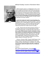
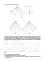
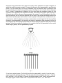
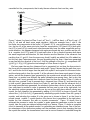
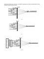
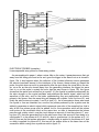
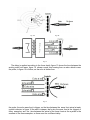
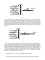
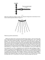
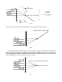
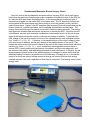
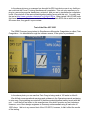
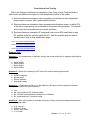
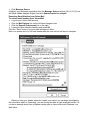
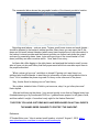
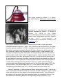
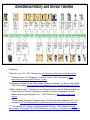
The M.E.T.A. Scholar 4th Ed., December, 2012 Thank You! ¡Gracias! Je vous remercie! Grazie! D ear Sponsor: On behalf of The Medical Equipment & Technology Association (META) team, we would like to thank you for showing your support and for sponsoring us. You dedicated support will open many new opportunities for these men and women within the Healthcare Technology Management field in order to continue developing their professional skills. Your contribution will enable them to participate in highly valued training and provide networking events that will broaden their discipline and character, on and off work, which is invaluable to our healthcare’s future. As you can imagine, there are expenses involved in managing a highcaliber team like this. You sponsorship will provide for our continued service and support that we provide for all of our members. Your contribution is not just a charitable gift, but also an advertising opportunity. Without the support of people like you, we would not be able to reach our goals. Thank you once again for you generous support of our team professionals. “Always Remember That M.E.T.A also spells TEAM” Very Respectfully, Dustin Telford, META President Almighty [email protected] Individual commitment to a group effort—that is what makes a team work, ~ Vincent Lombardi Keeping It Real….. Since 1975 Our comprehensive—out of the box—learning solutions, outstanding instructor support materials and customer service, and state of the art curriculum and hardware design combine to make Marcraft solutions the most cost effective and easiest to implement programs in the world. For over 30 years, Marcraft International Corporation has been producing electronics, computer, IT and mobile electronics training programs that excel in the classroom environment. We engineer and design the lab hardware, software and courseware materials for use in career and technical education schools around the globe . Marcraft has customers in all 50 states, the Canadian provinces and in more than 30 countries around the world. Marcraft s mission is to develop exceptional products for effectively teaching and training people the technical IT, computer, and electronics training skills in demand today and in the future. Marcraft Administrative Offices 1350 Spaulding Ave. WA 99352 Phone: (509) 374-1951 Fax: (509) 374-9250 Advertise Your Company What being a META sponsor can do for your dollars? Become a business partnership with META will… 1. Give your company the opportunity to have METAs 795+ members sample a new product or provide demonstration of a product or service from your company. We will supply marketing space for your products and services advertisement. 2. Provide a self-service marketing platform to promote your company profile, display company events and training classes offered, and grant your company access to our members contact information. 3. Start building newer and deeper area of networks by means of creating your company or product awareness and visibility within the Healthcare Technology Management community. What are the different sponsor packages? Tier 1—$200.00 (US) Tier 2—$400.00 (US) Tier 3—$600.00 (US) Tier 4—$800.00 (US) Tier 5—$1000.00 (US) To learn more please visit out link and sign up today. http://www.mymeta.org/sponsor_membership Christopher Correll, MSIMT, CBET, A+, is a Clinical Engineer Manager at Tyndall AFB, FL. He has 18 years of Clinical Engineering experience with focus on patient safety, technology management, incident investigation, etc. His professional experience includes multiaccount management and supervision, project management, safety, healthcare information technology, clinical research and investigation and educational program development for his organization. Chris is active in the BMET educational community by reviewing courses at the Vasquez Industries website’s Learning Management System and contributing to that curriculum. He is an administrator for BMETWiki; also META vice-president, and education co-chair. Alberto Vasquez, MSMOT CCE, CRES, CLES, CBET, is recently promoted to Assistant Professor and the Program Director for the Healthcare Technology Management Programs at St Philips College, a member of the Alamo Colleges in San Antonio, TX . These include the A.A.S in Biomedical Engineering Technology and an Advance Certificate in Healthcare Technology Management . As a certified Master Teacher, he is responsible for researching, planning and implementing the degree granting program and certificate. The BMET program includes course to qualify for the, A+, Net+ and Security+ certification exams, along with the fundamentals of medical devices in order to prepare for the CBET. He is also a small business owner of VC Clinical Engineering, an online certification and continuation educating industry. He is education chair for META. Editors’ Notes What famous engineer or scientist throughout history do you idolize? By Lub and Dub (for those of you who listened to the ‘car guys’, will understand this reference) How have engineers and scientist from the past inspired you? Looking in the glass mirror, I see my reflection and I am forever mindful of those people who made vast discoveries in mathematics, engineering, and science before me. I oftentimes wonder how will I forge a legacy of my own that will one day fit together within the community and ultimately make my own discoveries that will help others succeed. In any case, I cannot predict the future and those who already know me would tell you that I am too humble for fame. My payment is knowledge and I would conclude by saying exactly how much fun I have had along the way. I have studied great minds such as, Hieronymus Fabricius, Robert Boyle, Alessandro Volta, Michael Faraday, Georg Ohm, as well as Carl Gauss, Christian Doppler, Charles Wheatstone, Nikola Tesla, and more. All of which were great mathematicians, inventors, engineers, and scientists of their time. My absolute favorite is Nikola Tesla. A Croatian-born engineer who could speak eight languages, and almost single-handedly developed technology that harnessed the power of electricity for wireless household use. Nikola invented electrical generators, tFM radio, remote control, robots, spark plugs, fluorescent lights, and giant -a$$ machines that shoot enormous, lightning bolts all over the place —Tesla Coils. Tesla had an unyielding, photographic memory and an insane ability to visualize and simplify even the most complex pieces of machinery – the man did advanced calculus and physics equations in his head, memorized entire books at a time, and successfully pulled off scientific experiments that modern-day engineers STILL can't replicate. Nikola held 700 patents at the time of his death which qualifies him as “elite!” What does it mean to be a true engineer or scientist? Perhaps, it means to serve the public and devote yourself utterly to a set of high moral principles and standards. Possibly for us, it means to master the way of the electron. Or maybe it means to seek a calmness of your mind and remain passionate for those things which are “unknown” and investigate why. When we wake every morning we should devote ourselves to this style of perfection and always remain—disciplined! Here will be your first test… Remember there is no pass or fail and no certification for getting the right answer. I can only offer you one goal that we, as engineers, must achieve and that is—knowledge! Can you break this hacker’s code? M3rry chR1Stmaz AND hApPY n3w y3ARZ 3V3rY0N3 PHr0M M3ta. Editors’ Notes Howel “I saw the best minds of my generation destroyed by madness … Angel-headed hipsters burning for the ancient heavenly connection to the starry dynamo in the machinery of night” Quoted from Allen Ginsberg Special Points of Interest: Didactic Muses Case Studies College Grounds Certification Equipment & Diagnostics Medical Tech. History Highlights Games Comic Pro-Words Inside this Issue: Michael Faraday Hacker Detective Case Study: Simultaneous Monopolar Coagulation Michael Faraday: Inventor of the Electric Motor Michael Faraday was born on 22 September 1791 in south London, England. His family poor and Michael received only a basic education. When he was 14, he was a local bookbinders apprentice and during the next seven years, educated himself by reading books on a wide range of scientific subjects such as physics and chemistry. In 1812, He attended four lectures given by the chemist Humphrey Davy at the Royal Institution. Subsequently, he wrote to Davy asking for a job as his assistant. Davy turned him down but in 1813 appointed him to the job of chemical assistant at the Royal Institution. Michael Faraday A year later, Faraday was invited to accompany Davy and his wife on a European tour, taking in France, Switzerland, Italy and Belgium and meeting many influential scientists. In 1821 he published his work on electromagnetic rotation (the principle behind the electric motor). In 1826, he founded the Royal Institution's Friday Evening Discourses and in the same year the Christmas Lectures, both of which continue to this day. In 1831, Faraday discovered electromagnetic induction (i.e. the magnetic lines of force), the principle behind the electric transformer and generator. This discovery was crucial in his career. In 1833, Michael develops the laws of electrolysis. During the remainder of the decade he worked on developing his ideas about electricity. He was partly responsible for coining many familiar words including 'electrode', 'cathode' and 'ion'. Faraday's scientific knowledge was harnessed for practical use through official appointments, including scientific adviser to Trinity House (1836-1865) and Professor of Chemistry at the Royal Military Academy in Woolwich (1830-1851). However, in the early 1840s, Faraday's health began to deteriorate and he did less and less engineering and scientific research. He died on 25 August 1867 at Hampton Court, where he had been given official lodgings in recognition of his contribution to science. He gave his name to the 'farad', originally describing a unit of electrical charge but later a unit of electrical capacitance. Reference BBC, Michael Faraday Biography, Accessdate http:// www.bbc.co.uk/history/historic_figures/faraday_michael.shtml History Mole, Michael Faraday Timeline, Accessdate http:// www.historymole.com/cgi-bin/main/results.pl?theme=10011419 BASIC PHYSIC PRINCIPLES OF IMAGING ULTRASOUD II Eng. M.Sc. Rogelio Leyva Ochoa The purpose of this paper is to enhance the basic principles of the physic knowledge used in the technique of ultrasound imaging shown in the first paper, especially regarding ultrasound probes, to achieve it there have been included new topics, and also we have gone deepen into other ones briefly explained before. Learning objectives: Basic principles of ultrasound probes. In this article you will: Be able to describe how the mechanics ultrasound probes transmit the ultrasound lines needed to build the ultrasonic area. Be able to describe how the mechanics ultrasound probes receive the echoes coming from the tissues. Be able to describe how the electronics ultrasound probes transmit the ultrasound lines needed to build the ultrasonic area. Be able to describe how the electronics ultrasound probes receive the echoes coming from the tissues. Be able to describe how the electronics ultrasound delay to the echoes coming from near, middle and far field of diagnostic area. Be able to enumerate the advantages the electronic ultrasound probes have over the mechanic ones. Be able to enumerate the basic differences between the mechanics and electronics ultrasounds probes. Be able to describe how phase array probes transmit the ultrasound lines. Topics 1. Mechanic probes i. transmission and reception 2. Linear array probes i. delay time Ii. line generation Iii. focusing Vi. echo generation 3. Convex probes. 4. Phase array probes i. transmission and reception Ii. continuous focalization in reception ULTRASOUND PROBES MECHANIC PROBES (transmission and reception). Sectorial ultrasound image probes. Though mechanic probes are not widely used as electronic ones at this time, it is useful to know how they work for understanding better the electric ones. As was explained before the ultrasound area is built with ultrasound lines, as seen in figure 1, the mechanic probes generate the ultrasonic lines one by one, using only one crystal (remember that crystal in this paper means is a quartz crystal or other combine materials, with the piezoelectric properties), though ultrasound probes may have more than one crystal depending the kind of mechanic probe. In this paper the ultrasound area is defined by two axes, (x,y), the y-axis is in the center of the area and has the direction other central ultrasound line emitted by the ultrasound probe, and the x axis has a 900angle respect the y axis as is shown in figure 1, at the left, x is negative, and positive at the right, besides all the lines emitted by the crystals have the same strength, that is why when two lines are added, and the y components have opposite sing, they cancel each other. Here we explain two types on mechanic probes; one of them has a crystal which swings as a clock pendulum, and another has three crystals going around an axis. The one that swings has just only one crystal which at the beginning of the generated area is localized at the left of the ultrasound area where the first line has to be, as is shown in figure1, the crystal receives the electric pulse needed for sending the ultrasonic beam, then it waits for the echoes coming from the tissues the ultrasonic beam has passed through, when the last echo is received, a motor moves the crystal to the place where the line 2 is going to be generated as shown in figure 2, the same crystal transmits the ultrasonic beam and receives Fig.1 Fig.2 Fig.3 the echoes the same way as before, then at the end of the reception the motor moves again the crystal, but now to the place where the line 3 is going to be generated and so forth, this process is repeated until the crystal reaches the line 7 as is shown in figure 3, now when the last echo is received, the motor moves the crystal to the initial position in order to generates the first line of the next ultrasound area. The mechanic probe with crystals that go around an axis have three crystals separated a 60 angle, as seen in figure 3. At the beginning the crystal 1 is at the site where the first line (point A) will be generated, from here to (point B), the procedures is the same as the one done by the pendulum probe, but after the last echo is received from the last line (point B), the motor move the crystal in the same direction, away from the ultrasound area and at the same time the crystal 2 is located at the line 1 (point A) in order to generate another ultrasound area, and the process is repeated until the crystal 2 reach the line 7 that is moved away from the ultrasound area and then the crystal 3 is located in the first line of the coming ultrasound area, and the process is repeated all the time the probe is sending ultrasonic lines. 0 ELECTRONIC PROBES (transmission). Linear sequential array probes, or linear array probes. We begin to explain the electronic probe which generates a rectangular ultrasonic area as seen in figure 5, the linear array probes have more than one crystal, in this explanation we refer to figure5, in which the probe has seven crystals. The way an ultrasonic line is generated by an electronic probe is not the same way it is done by mechanic ones, in electronic way an ultrasonic line is generated by more than one crystal as seen in the figure 6, let us focus first in ultrasonic line 3, crystal 3 generates an ultrasonic line the same way the mechanic probes do, the crystals 2 and 4 generate one ultrasonic line each, these ends at the same point (Focus), at this point also end the ultrasonic lines generated by crystals 1 and 5.According to the Huygens's principles, the net acoustic signal is the net sum of the signals that have arrived from each source (in this paper each source is each crystal). At this point the contribution of every element is added in phase to produce a peak in the acoustic signal. At the focus, all the ultrasonic lines generated by the crystals are added to generate a new ultrasonic line that is the ultrasonic line which will go deep inside the human body as happened with the mechanic probes. Taking the crystals as reference, let`s consider that the line generated by the crystal 3has00angle (y-axis), the line generated by crystal Fig.4 Fig. 5 2 is at some angle degree–x0(at the left) and the line generated by crystal 4 is at the same angle degree but with opposite sign+x0(at the right), and also it happen with line 1 –x0(at the left), and line 5 +x0(at the right), of course the angle degree of lines 1 and 5 are bigger than the angle degree of lines 2 and 4.The x components of the lines 1, 2, 4 and 5 are cancelled but the y components, that is why the new ultrasonic line is on the y axis. Fig. 6 Figure 7 shows five lines(+xA0line 5 and -xA0 line 1), (+xB0line 4and –x B0line 2),and (00 Line 3), xA and xB have some angle deviation, taking as example lines 1 and 5, the line1have two components at the focus, L1F(y)and L1F(-x), one positive and another negative, the line L5 at the same point also have two components, L5F(y)and L5F(x),both positive,L1F(-x) and L5F(x) cancel each other because they have the same magnitude and opposite direction, this happens because both angles are equals but one positive and the other is negative, but L1F(y) and L5F(y) add each other in the y direction because both have the same magnitude and direction, so their direction are the direction of the ultrasonic line resulting from L1 and L5, then the same way linesL2 andL4 are added, line L3is added too but this only has 00axiscomponent, this way by adding this five lines, it has been generated a new line with the direction of the line 3, with the strength of the four (y) components L2F (y),L4F(y), L1F(y), L5F(y)plus the total strength of L3 as shown in figure 7. We have seen the way the ultrasound line is generated, but not how the lines arrive to the focus with the appropriated direction and angle. Figure 8 shows that the path from crystal 1 and 5to the focus is larger than the path from crystal 2 and crystal 4 to the same focus, and the shorter path is from the crystal 3, all the ultrasonic lines have equal speed of propagation, and all the ultrasonic lines generated by the crystals must arrived at the focus at the same time, no matter how different the paths distances are among them, that is why the crystals 1 and 5 must generate their ultrasonic lines first than the others (Pulse t1), later at the right time, crystals 2 and 4 generate their ultrasonic lines (Pulse t2), and later also just in time crystal 3 generates the center line (Pulse t3), and this way the first ultrasonic line of the image area has been generated, the mechanic probes has a motor to move the crystals from one place to another in order to generate the lines one by one at the right place, but the electronic probes generate the lines one by one at the right place without moving any crystal, the first ultrasonic line generated by adding L(1+2+3+4+5) is shown in figure 8, the second line [ L(2+3+4+5+6) ] is generated by eliminating crystal number 1from the group of crystals, and including the number 6 in the group as is shown in figure 9, so the focus is moved toward number 7 crystal direction, the second line is generated in the right place, beside the first ultrasonic line with no crystals movements. Figure 10 shows how is achieved the process to excite the crystals, a pulse generator generates a pulse for each crystal, later the pulse are delayed electronically by a device. Figure 11 shows a complete circuit to transmits all the pulses needed for generating an ultrasound area. One of the better advantages of the electronics probes over the mechanic ones is that changing the time the crystal are excited, the transmission focus can be moved forward or backward along the ultrasound interest area, and also is possible to generate more than one transmission focus allowing a longer focal zone area. Fig. 8 Fig. 9 Fig. 10 Fig. 11 ELECTRONC PROBES (reception) Linear sequential array probes or linear array probes. As was explained in paper I, when a stone falls on the water, it generates waves that get away from the falling point and as far as it goes the bigger is the wave front as is shown in figure 12a, it also happens when the reflection of the incident ultrasonic waves generates the echoes (mechanic waves) in the interfaces of the tissues, these echoes go toward the probe, the point where an echo is generated is alike the spot where the stone falls in the water, so as far as the echo travels away from the generating interface, the bigger his wave front is, so at the probe´s crystals the echo has the way shown in figure 12b, this figure shows that the wave front arrives first at crystal 3 (t1),the crystal is pressed mechanically by the echo strength so the crystal oscillates and produces the electric signal, which has the waveform of the echo, and for the better understanding they are represented as electric pulses in the figures, then the same thing will happen with crystals 2 and 4 at time (t2), and finally the echo arrives at crystals 1 and 5 at time (t3). As in transmission there were used five crystal to form an ultrasonic line, now the five pulses produced by the crystals must be added to generates an electric signal which represents one echo of the reception line, that is why all the five pulses group must be added, but for the summation action all the pulses must arrive at the summation block at the same time, so alike in transmission the pulses pass through a delay circuit, now the circuit delays an amount of time the pulse at t1, coming from (L3), that was generated first by the echo wave front, this amount of time delay is to synchronize t1 to the pulses at t2 (L2 and L4), also to synchronize it to the pulses at t3, (L1 and L5) that are the last pulses generated, a smaller delay is applied to the pulses at t2, and no delay is applied for pulses at t3, this way all the pulses arrive at the same time at the summation block coming from crystals as seen in figure 13. Fig. 12a Fig. 12b Fig. 13 The delay is applied according to the focus depth, figure 13 shows the time between the arriving echo front wave, figure 14 shows a wave front coming from an echo which is near the probe, in figure 15 is further, as the echo is farther from Fig. 14 the probe, the echo wave front is bigger, so the time between the wave front arrival at each crystal is shorter, in figure 16 the echo is deeper, that´s why the wave front is the biggest of three examples, and the time between the arrival of the wave fronts at the crystals is the smallest of the three examples, so there must be a different delay Fig. 15 for each focus depths for all the group of pulses to arrive on time at the summation block. Commercial ultrasound machines have two, three or more delay circuit, one for each focal zone. wave front is the biggest of three examples, and the time between the arrival of the wave fronts at the crystals is the smallest of the three examples, so there must be a different delay for each focus depths for all the group of pulses to arrive on time at the summation block. Commercial ultrasound machines have two, three or more delay circuit, one for each focal zone. Fig. 16 Even there are machines that have a dynamic focalization system, this technology does not have focal zones, instead the focal zone is reduced to a pixel zone and as the pixels are so close one another the focalization is considered a continuous focalization along the reception echo line with many pixels generating many echoes, so there are focus at each pixel as shown in figure 17, then every time each echo arrive at the probe, a different delay is done, and a summation is also done for each delay, this offer a better image quality because the synchronization needed for the summation is continuous, this process was implemented in 1976 by von Ramm and Thurstones. Curvilinear probes, or convex probes, (Sectorial ultrasound image) This type of probe works the same way the linear probes do, but as the surface shape Fig.17 where the crystals are arrange is convex, the ultrasound image area is sectorial as the mechanic ultrasound probes as seen in figure 18. Fig.18 Phase array probes (transmission) Phase array probes work in some way like linear array probes do, but as is shown infigure19, these transmit lines with different amount of angle regarding the y axis to build the shape of the sector ultrasound image, in the example of the figure 19, the probe uses 4crystals 1,2,4, and 4,the pulses that activate the crystals are delayed sequentially in time, no signal coming from the crystal have the same delay as happen in sequential probes (figure 8), the crystal 1 is activated first, and crystal 4 is the last, this way the four lines arrive at the focus at same time; now let’s pay attention only to the lines 1 and 4 by now, as was explained before, at this point all the line are added, the adding of line 1 plus line 4 generate a new lineL1(x,y) + L4(0,y)=L1L4(x1,y1-4), L1 has components in x and y, but L4 have only one component in y so the x components do not cancel each other as happen in figure 7 ( where L1(x) and L5(-x) have opposite signs), here as L4(x) = 0, L1(x)forces the new line to have an angle different from 00regarding the y axis, this way the new line has been steered to the right of the center line, and this angle of deviation of the new line will be bigger or smaller according of the angle of L1(x). Nowlet’s focusing to all the lines of figure 19,the resulting line has a deviation angle to the right on account of L1(x), L2(x) and L3(x), as they have equal sign, their x components do not cancel, instead they add each other and Fig.19 the total strength of the line is dependent of L1(x,y)+L2(x,y)+L3(x,y)+ L4(y). Fig.20 The analysis of figure 20 is similar to the one done in figure 19, but the lines taken into account in figure 21 are at the opposite sites of the ones taken into account in figure 20, so the x components steer the resultant line to the left of the central line as is seen in figure 20 and is dependent of L7(x,y) + L6(x,y) + L5(x,y) + L4(y). Fig.21 Figure 21sows the same array of figure 19 and 20, but the resultant line from the adding action is a straight line along the y axis, the analysis is similar to the one done in figure 7, L6(x) - L(2), and L(5) – L(3)cancel each other, as these line components are the ones that contribute to the deviation angle, the resultant line is a straight ultrasonic line along the y axis = L2 (x,y) + L3(x,y) + L4(y) + L5(x,y)+ L6(x,y). Reference The Physics of Medical Imaging. Steve Webb.IOP Publishing LTD, a Company Wholly Owned by the Institute of Physics, London. 1992. The Biomedical Engineering Handbook. Third Edition. Joseph D. Bronzino. © 2006 by Taylor & Francis Group, LLC. CRC Press is an imprint of Taylor & Francis Group Service manual Aloka SSD 5500. Aloka Ultrasound Systems 2005, 22-1, Mure 6 chome, Mitaka-Shi, Tokio 181-8622, Japan. Random Quiz: Question 1:The transmission focus in the linear probes are obtained by________ a. b. c. d. adding lines transmitted from the crystals means of a convex mirror inside the probe amplifying the transmitted lines activate all the crystal of the probe Question 2:To build ultrasound lines in transmission, and the echoes in reception is necessary___________ a. b. c. d. to modulate the pulses to delay in time the pulses to apply a logarithm amplification to filter the pulses Question 3:The phase array probes build the sector ultrasound image by_______ a. b. c. d. steering the ultrasonic lines sending half of the total line first and another half later sending the ultrasonic lines with an angle of 45 degree sending the ultrasonic lines with three focus Question 4:Enumerate three examples that shows the advantage of the electronic probes over the mechanic ones._____ ______ ______ a. b. c. d. e. The possibility of move the focus along the image area The possibility of focusing continuously the reception of echoes Eliminate the complexity of mechanic devices Electronic probes are smaller It is possible to obtain images in B and M mode Question 5: The focus build by the ultrasound probes is done under the___________ principle. a. Huygens’ b. Ramm and Thurstones’ c. Somers` d. Gauss` Question 6: The summation device located after the delay line circuits __________ a. synchronizes the echoes b. outputs a signal which is representative to the original echo c. adds the smaller echoes d. stabilize the level of the echoes Answers: 1a 2b 3a 4a,b,c 5a 6b Could Simultaneous Monopolar Electro Surgery be Safer? By Gregory J. Ward I just can’t tell you how fascinating it is to me, that you can actually pass electricity through the human body, as long as it is above 350 KHz, with no negative physiological effects to the patient. Since I learned that I have been on a quest gathering data, videos, and photos on simultaneous monopolar coagulation and cut sub modes. I have also spent quite a bit of time, talking with surgery nurses who have actually been involved with cases during simultaneous coagulation. On the other hand, I have talked with nurses who work with Cardiovascular Surgeons who will not allow the use of simultaneous coagulation in their OR room. Some feel this mode has some potential patient safety issues. I was very pleased to be able to share some of my finding, so as to get some feedback from the overall biomed population. After reviewing this article, we would like to hear from others on this subject who can share their findings, and viewpoints. CONMED Biomed technical training It was in 2004 that I started to get interested in electro surgery. It just seemed I needed to know more about this device, so I researched ESU schools. In early 2005 I attended Conmed Technical Training at their facility in Colorado, and to say the least I had a blast. Our instructor, Mike Manes was one of the engineers who actually designed the Excalibur, which is widely used in the medical field even today. Of all the units I liked the System 5000 the best, and so that became the unit that I decided to learn the most about. We discussed each different unit, and followed signal paths through them, and learned about different components inside and what they did as well. One part of the coarse discussed PM’s, and we all had to set up and do a full PM on most of the units, following the procedures in the technical manuals we were given. At the end of the coarse we all had to trouble shoot units with bugs, and owe what fun we had finding those planted bugs. It wasn’t until I was on the plane heading back home that I realized, we didn’t go over testing the simultaneous monopolar sub mode. We only discussed the internal dip switches that allowed you to turn on either dual cut, or dual coag, but not the operation of the sub mode itself. Erbe USA Biomed technical training Erbe was next on my list so off to Georgia I went to attend factory technical training for biomed. The main instructor was Rick Stewart, who may still be there, as far as I know. This school was a bit different than Conmed, in that they recommend testing the unit output readings in current, instead of power, which is fine with me. We went over all their units in the course, but it was the VIO 300D that caught my attention. It’s basically a pc based ESU, in a nutshell, and is menu driven so to speak. And since my facility had 3 of the units, I decided early on that I would start to study this unit’s ability to deliver simultaneous monopolar electrocautery. I paid particular attention to every detail and the mode was not even discussed, much to my dismay. While working with a unit I was able to find Erbe’s Twin Coag monopolar sub mode. In the above photo you can see the menu that allows you to select Twin Coag. I was fairly excited about getting back to my hospital so I could look into this mode and learn more in detail about it. I was starting to notice a pattern in the simultaneous coagulation arena; it seemed that this mode didn’t get a lot of attention. I was not quite certain why, since this mode had an advantage over most generators that didn’t have it, two surgeons could use the ESU at the same time. We all know the value of real estate around the OR table during surgery. VALLEYLAB Biomed technical training It was a little over year or so later before I could attend Valleylab ESU technical training for biomed, which was held in Arizona. It was shortly after the release of the TRIAD unit, that I attended school and though we went over the different models, I was curious if Valleylabs new unit had simultaneous monopolar capabilities. I finally got my chance to ask the instructor if the TRIAD has simultaneous monopolar coagulation, and what a surprise, when he said they had eliminated it from this unit. Monopolar Electro Surgery Circuit Let’s start by reviewing basic monopolar electro surgery (ESU) circuit path theory. We know that electricity flows through every component one after the other, in the ESU until it exits the ESU and enters the hand piece. The RF waveform will then enter the patient at the point where the doctor starts to touch the patient’s tissue and activate his hand piece. It’s the RF waveform that will actually heat up the fluids in each cell until it explodes and becomes smoke plum. The energy then travels through the patient’s body until it finds the return electrode. The energy then enters the metallic plate and travels up the wire to reenter the ESU. In plain electronics talk we simply have a series circuit here, that’s all. We remember from school that in a series circuit current is common and voltage is additive. In our series circuit we have a source (ESU), a path (the hand piece, the patient, and the return electrode), and a resistor (the patient, and application technique). The illustration above shows the equipment, minus the patient, to complete the monopolar electro surgery circuit. Simultaneous Monopolar Electro Surgery Circuit Now let’s look at the simultaneous monopolar electro surgery (ESU) circuit path theory. Like before the electricity flows through every component one after the other, in the ESU until it exits the ESU and enters the hand pieces. In this monopolar sub mode you have 2 hand pieces plugged into the same ESU, at the same time. The RF waveform will then enter the patient at the point where each doctor starts to touch the patient’s tissue, and activate his hand piece. Again it’s the RF waveform [the frequency] that will actually heat up the fluids in each cell, at each hand piece, until it explodes and becomes smoke plume. The energy then travels through the patient’s body until it finds the return electrode. The energy then enters the metallic plate and travels up the wire to reenter the ESU. Now this circuit is a bit different, we have now created a combination series parallel circuit. In this circuit type again in the series portion the current is common and voltage is additive. That means the total voltage of the circuit is equal to the sum of the voltages across each individual resistor (e.g. Vtotal = V1 + V2 + V3 ...). However, in the parallel portion of the circuit voltage is common and current is additive, across each branch of the parallel portion of the circuit. That means the total current of the circuit is equal to the sum of the current across each individual resistor (e.g. Itotal = I1 + I2 + I3 ...). In our combination series parallel circuit we have a source (ESU), circuit paths (both hand pieces, the patient, and the return electrode), and two resistors (the patient, and application technique at each hand piece). In Physics, the additive property of power is due to the additive property of voltage in a series circuit and the additive property of current in a parallel circuit. Another way of looking at it is; if several elements in a circuit are using a certain amount of energy per second then the total energy used per second is the sum, regardless of how they're configured. Total energy used is total energy used. The illustration above shows the equipment, with two hand pieces plugged into the monopolar active outputs, forming the parallel portion of the combination series parallel circuit path for simultaneous monopolar electro surgery. In 2005, I started researching and testing different manufactures ESU’s simultaneous monopolar coagulation mode. I decided I needed help, so at the time I had a Gold Membership to ECRI’s on line database. I also had the product comparison option as well, which made my research a bit easier to do. So I only wanted to test units that had disclosed to ECRI, that they had the simultaneous monopolar capabilities. The 3 that I chose were the ERBE Vio300D, Conmed System 5000, and Valleylab Force FX. After reviewing the technical manuals of the three chosen units, I was unable to find a test procedure for simultaneous monopolar coagulation/cut. In ANSI/AAMI HF18 1993 section 4.1.3 titled “ Service Manual “ , it is recommended that the service manual have, Calibration procedures, and Preventative Maintenance procedures (test procedures). Simultaneous Monopolar testing method We now needed to develop a way to test the power output while simultaneously energizing both monopolar out hand pieces. For testing this circuit we simply put a Dynatech 454A electrosurgical analyzer on each parallel branch of the combination series parallel circuit that is formed when using this mode. The grounds are tied together so as to simulate a realistic test scenario. By doing this we will be able to read the delivered power of each hand piece. In the above photo Sales Rep. Johnny Boatwright, of Erbe USA is filming me while testing the VIO 300 D in Twin Coag mode. I am illustrating to him the “Power Shift” between the hand pieces during Twin Coag when one surgeon deactivates his hand piece and the other surgeon is still activating his. Testing the Conmed System 5000 We decided we would use 100 watts as our power setting for all testing, to make comparing results between manufacturers easy. The loads used for this test were, 150, 250, 300, 500, and 1000 Ohms. By using a wide variety of load values we satisfied feedback from on design engineer at ERBE who questioned our load values. On this unit we decided to test both the Dual Coag, and the Dual Cut sub mode of the monopolar feature. Below are the results of the power delivered from each hand piece (on the Dynatech 454A electrosurgical analyzer), while activating simultaneously, with a power setting of 100 watts (set into the Coagulation display). For purposes of testing we will refer to one active hand piece belonging to the primary surgeon, and the second active hand piece as belonging to the secondary surgeon. Results for Dual Cut had the same characteristics as Dual Coag (Simultaneous Coagulation). Simultaneous Coagulation (100W setting) Primary Surgeon Second Surgeon 150 Ohms 15.3 watts 150 Ohms 15.9 watts 250 Ohms 23 watts 250 Ohms 25 watts 300 Ohms 27.5 watts 300 Ohms 30 watts 500 Ohms 40.9 watts 500 Ohms 45 watts 1000 Ohms 44.5 watts 1000 Ohms 51 watts If you study the chart above you will notice that we have a very interesting situation, in that even though we set the unit 100 watts on the display, the unit only delivered roughly half of the power to each electrosurgical analyzer via the hand pieces. As you can see, the lower the ohmic value the worst the wattage measurement (e.g. prim surgeon using a hand piece at 150 ohms on the unit had delivered and recorded 15.3W that is 15.3% of the rated output out of 100W. Recall that it should be close to 80% as stated earlier) taken. The reason this happens we discovered is because there is a parallel circuit formed, as soon as a second hand piece is plugged into the unit. The results immediately raised some concerns about simultaneous electrocautery. In ANSI/AAMI HF18 1993, 4.4 titled, Accuracy of Performance specifications, section 4.1: b and c. B; states that the output power versus load resistance shall be within 20% of the stated value, since there is no test procedure in the manufacturers service manual, we used the above loads which show at 500 ohms the unit delivered roughly 50 % of the set power at each hand piece, we find this to be out of compliance with the standard. C; states that the output power versus control setting shall be within 20% of the stated value. We set in 100 watts the unit delivered 50 watts to each hand piece; we found this to be out of compliance with the standard as well. This led us to realize another situation that we feel is an area of concern. We are talking about Simultaneous monopolar sub modes that uses 2 active hand pieces ; however there is only one power setting control and one power setting indicator. It would only seem natural to have a separate power setting and indicator for each active hand piece, this way each surgeon would be able to set and control his desired power, and at a glance look at the unit to see what the setting is. The power shift from hand piece to hand piece After repeating the test several times, we accidentally stumbled upon another potential patient safety issue. We notice that if one surgeon was activating his hand piece and the other surgeon was not, the unit would deliver the set in power 100 watts (+/- 20 %). Now, if one surgeon was activating his hand piece, and the other surgeon started to activated his hand piece roughly half of the set in power would immediately shift to the secondary surgeon. This is a significant amount of power, to have 50 watts (50%) of power just shift from one hand piece to the other hand piece during surgery could render a potential patient safety issue at the activation site. Test of the Valleylab Force FX In the above picture a co-manager has brought his ESU test device over to my facility so we could test the Force FX during simultaneous coagulation. This unit only requires you to plug in a second monopolar hand piece, activate it, and you are in simultaneous coagulation mode. We noted all of the same potential patient safety issues with this unit. You may view the test at http://www.youtube.com/watch?v=3zYhbU1EExs. Other tested VALLEYLAB units that have the same safety issues noted are: The Force 2, which ECRI did an article on in the 90s some time, they gave it a poor review. Test of the Erbe VIO 300D The ERBE Company’s equivalent to Simultaneous Monopolar Coagulation is called, Twin Coagulation. It is selectable through the software menus, if the option is purchased. In the above photo you can see that Twin Coag is being used at 100 watts in effect 8. We did find some operational warnings and guidance in the Operators manual pertaining to twin coag. During testing we noted all of the same potential patient safety issues with this unit. I sent the first test video to this manufacturer; they didn’t question my test technique. However, one of their design engineers in Germany recommended using a load value of 1000 ohms. I did so in my second test of the VIO 300 D, however, it didn’t affect the results of the testing. Conclusion of our Testing With a few changes, simultaneous coagulation (Twin Coag or Dual Coag) would be a safer mode, and allow each surgeon to have independent control of his power. 1. Each simultaneous monopolar output receptacle should have its own independent power output controller, and a power setting indicator. 2. Each simultaneous monopolar output receptacle should deliver power, to within 20% of the set in power setting, as is indicated on the power setting indicator. This should also be true during simultaneous monopolar activation. 3. Each simultaneous monopolar HF receptacle output on an ESU shall have its own RF amplifier within the circuitry inside the unit. And this amplifier shall not have a parallel output after its final amplification stage. Link1: http://youtu.be/QR0rUtisRJM Link2: http://youtu.be/W2IfP3Wd9vc Link3: http://youtu.be/Cq4qvoB0Px8 Random Quiz: Question 1: The transmission of electricity through the human body with no negative physiological effects are? a. b. c. d. Below 350Hz Above 250Hz Below 250Hz Above 350Hz Question 2: Which of the following is NOT part of the normal electrosurgical setup? a. b. c. d. Patient headpiece Bipolar leads Return electrode Monopolar Leads Question 3: A Technician set the unit on the display to 100 watts, the test equipment measures 69.95 watts. Is the device within tolerance> a. b. c. d. Yes No, its exceeds the 10% tolerance rating No, it should measure between 80watts out of 100watts No, its exceeds the 5% tolerance rating Question 4: Who was a student of a student of Harvey Cushing and first developed the electrosurgical device used today? a. b. c. d. N.W. Cornell William T. Bovie Arthur Tracy Cabot G. H. Liebel Answers: 1.d 2. a. 3. c 4. b The Hacker Detective By Chris Correll Learning Objective: An appreciation for ethical hacking development for modern day Biomedical Technicians. There was a sharp wind blowing that night as the rain drops violently clobbered against my window. It was one of those dreary, muggy nights with sweat beating upon my brow, reading my favorite article and only a glass of single malt scotch to wet my palate. It is a little slice of Paris …I always say…at least while I wait for my 1951 series Dragnet to finish streaming. My name is Kevin Timnick, I was once a convicted criminal and world’s most famous hacker turned security specialist. Anything can happen on dull night like this when all of a sudden an anonymous email pops up and into my inbox. Ring! Ring!! It was the phone; and on the other end it was from a certain Henry Homeowner. I answered the phone as, “Hacker Detective here…how may I help you?” The anonymous caller on the other end of the line said, “Kevin, it is Henry and I am in a heap of trouble. I didn’t know who to turn to.” I told him to, “Calm down!” “ I asked Henry, “What is the problem?” Henry went on to explain that he was surfing the internet for beer recipes and all of a sudden a mysterious email popped into his inbox. He continued saying that the email did look suspicious but it had been sent from one of his many contacts listed in his Hotmail account. He said, “Kevin I know it was dumb but I just opened the email…I’m so sorry!!!” “You really shouldn’t have!” Kevin said, “I know and now, I am getting phone calls and email replies from all my contacts asking me why I sent them this bad link and so happens is that one of them is my boss who is blaming me”, said Henry frantically. “I thought I could trust you!” said Henry’s boss. And Henry kept rambling on and on. After I calmed down Henry, I then proceed to look over the suspicious email that he had sent to me only a few moments ago. Here is a screenshot of what his email looked like. Almost immediately, a number of red flags go up as I, The Hacker Detective, get to the bottom of it. First rule of detective work is informing the clients to never click any links from random anonymous emails no matter how legit it might be. Ronald Reagan once said, “Trust but verify!”—and very good words to live by. The reason is Henry could have a malevolent virus installed onto his computer stealing his passwords, user names, or other personnel information (i.e. bank accounts, social security numbers, credit cards, key dates, etc.). By clicking the link and Henry entering his new information the hacker is stealing his information once he press sends. All Henry sees is a link that says the email originated from “technicalservices.com” when in fact the email can be disguised and instead your information sent straight to my hotmail account. Actually, hackers will masquerade as someone else’s identity with made up (spoofed) email names and spoofed email addresses to gain access to targeted system. An elite hacker will cover up his malicious intent even further by embedding a Trojan virus (i.e. ACAD/Medre.A) inside a link and when you click the link he or she downloads a worm for the hacker to steal your information and finally deleting its tracks. Truthfully, being a hacker detective requires you to able to extract and figure out email header information regardless of what email client you are using. All you are trying to do is extract the complete email header that tells the detective effectively the route (path) taken from the sender (hacker) to your machine (the victim). Lastly, many known internet providers will purposefully strip out a lot of the information to include the senders exact street address; therefore you can only track the IP address as far as the internet provider.1 On the other hand, knowing the hackers internet provider can and will prove very resourceful later on for reporting purposes. The following are some ways to extract email headers by email client: Extracting Email Headers from Gmail To extract email headers from Gmail: 1. Open the email message. 2. Click the down arrow adjacent to the Reply link in the upper-right corner of the email message 3. Click Show Original. Copy and paste the header information into the Email Header Analysis Engine, and click Submit header for analysis Extracting Email Headers from Hotmail To extract email headers from Hotmail: 1. Login to your Hotmail account. 2. Click on Options tab on the top navigation bar 3. Click on the Mail Display Settings link 4. Change the Message Headers option to Full 5. Click the OK button Copy and paste the header information into the Email Header Analysis Engine, and click Submit header for analysis Extracting Email Headers from Microsoft Outlook 2010 To extract email headers from Microsoft Outlook 2010: 1. Click the File 2. Click Properties 3. Locate Internet Headers (bottom of the popup window) Highlight, copy and paste everything from the Message Source window (Ctrl-A, Ctrl-C) into the Email Header Analysis Engine, and click Submit header for analysis Extracting Email Headers from Microsoft Exchange To extract email headers from Microsoft Exchange: 1. To get the complete headers and message source using Microsoft Exchange Click the File menu 2. Click Properties 3. Click the Details tab 1. Click Message Source Highlight, copy and paste everything from the Message Source window (Ctrl-A, Ctrl-C) into the Email Header Analysis Engine, and click Submit header for analysis Extracting Email Headers from Yahoo Mail To extract email headers from Yahoo Mail: 1. Log into your Yahoo! Mail account. 2. Click the Mail Options link on the left-hand navigation bar. 3. Click the General Preferences link on the right. 4. Locate the Show Headers heading and select All Click the "Save" button to put your new settings into effect. Next, is a screen shot of a full email header and the code that we will have to decipher. When you have your header extracted, copied, and saved, you can begin investigating the information within it. Essentially, you are turning the tides to track down the hacker. Let us use an example email from a Nigerian hacker sent to Henry’s Microsoft Windows Live Mail Inbox: Incoming full header: X-Message-Delivery: Vj0xLjE7dXM9MDtsPTA7YT0wO0Q9MjtTQ0w9Ng== X-Message-Status: n:0 X-SID-PRA: Mr. Peter Phillip < [email protected] > X-SID-Result: Fail X-Message-Info: jXuon5/YRm68Ci7Ivfe0Hv/ KIFdVOY7XxLdfBnLCvCwn8JjE0pGP8W0ZNZ36B7/RyRDsMPlTFqG4/ uQV8yk1AMg7CiHXhUBi Received: from mail.cyb.asp-p.jp ([164.46.139.108]) by col0-mc3f18.Col0.hotmail.com with Microsoft SMTPSVC(6.0.3790.3959); Mon, 26 Jan 2009 10:48:49 -0800 Received: from User ([41.222.67.140]) (authenticated (0 bits)) by mail.cyb.asp-p.jp (8.12.11.20060829/8.11.3) with ESMTP id n02DqpHu020392; Fri, 2 Jan 2009 22:52:54 +0900 Message-Id: <[email protected]> Reply-To: <[email protected]> From: "Technical Support Services"<[email protected]> Subject: System Password Reset Date: Fri, 2 Jan 2009 14:53:22 +0100 MIME-Version: 1.0 Content-Type: text/plain; charset="Windows-1251" Content-Transfer-Encoding: 7bit X-Priority: 3 X-MSMail-Priority: Normal X-Mailer: Microsoft Outlook Express 6.00.2600.0000 X-MimeOLE: Produced By Microsoft MimeOLE V6.00.2600.0000 Bcc: Return-Path: [email protected] X-OriginalArrivalTime: 26 Jan 2009 18:48:49.0731 (UTC) FILETIME= [BA0BC930:01C97FE6] Some details are obvious without any further use of software tools. In a future article, perhaps we will further analyze and decipher this code without software tools but for now let us continue. Afterward to get more information about our hacker, our next step is to submit the email header to an email header analysis tool such as http://www.iptrackeronline.com/ email-header-analysis.php. This site has a brief tutorial on how to extract and submit email headers for analysis and it is completely free to use. We will simply follow these few steps to investigate our hacker’s whereabouts. 1). Copy and paste our email header data and click “submit header for analysis.” Next, locate to the far right the “originating IP address” this is the hacker’s original IP address from where he sent Henry that malicious email. Also, note that the hostname, original email address, and latitude and longitude of the hacker’s origins are present. What can we do with this information Hacker Detective? Well, you can input his “latitude and longitude” into Google maps for a street view or satellite map of his internet providers city and state or country. Additionally, we can perform a WHOIS command and that will tell us more specific details about the originating IP Addresses provider as well as an address and phone number to report abuse. In our example, “8.12.11.200”, originating IP address, belongs to a providers name “Level 3 Communications”. A WHOIS search reveals that the company is out of Broomfield, CO and that a phone number and email is listed to report this type of malicious conduct. The screenshot below shows the geographic location of the internet provider’s location. Reporting email abuse -- such as spam, Trojans, email borne viruses and email threats -should be directed to the hacker’s internet provider. Many times you can report the IP Address and full email Internet Headers (which many times contain time-of-day information) to the hacker’s internet provider and the internet provider can further track down the unique end-user (by examining dates, times, login and logout logs of the stored hacker’s IP address) and they can take corrective action. Now, back to our story… As Kevin did a little digging in the right places, and analyzed the hacker’s email, he was able to figure out who sent Henry that nasty spam email and Kevin was able report them to the proper authorities! "What a clever girl you are,” said Kevin to himself. Figuring out it was Henry’s exgirlfriend who hired the hacker to steal Henry’s information so she could get back at him in court." All of a sudden the phone rings and it’s Henry on the other end of the phone. “Hey, thanks Kevin for helping me out!” said Henry. “No problem, dude but listen I’ll talk to you tomorrow, okay. I’ve got other plans now” Kevin replied. After we both hang up the phone, I turn around quickly to see that my Dragnet video has finished streaming on my homemade DVR box. I grabbed some popcorn, a tall glass of milk, and then called it a night—it’s another lonely night for the Hacker Detective! THE STORY YOU HAVE JUST READ MAY HAVE BEEN BASED ON ACTUAL EVENTS. THE NAMES WERE CHANGED TO PROTECT THE INNOCENT. Reference IPTrackerOnline.com. “How to extract email headers, a tutorial”. August 1, 2012. http:// www.iptrackeronline.com/how-to-extract-email-headers.php ANESTHESIA DELIVERY AND DEVICE TIMELINE In the beginning, anesthesia delivery had been traditionally been administered in dental surgical procedures by way of a cloth and Analgesic drugs that would reduce sensory, motor and sympathetic nerve transmissions at the level of the brain, resulting in lack of sensation (unconsciousness). Afterward, anesthesia equipment became a wide spread means of delivery for anesthesia using simple pneumatic devices. Where did it all begin? At present, scientists and other scholars are working hard tracing back ancient writings of the ancient Sumerians, Babylonians, Assyrians, Egyptians, Greeks, Romans, and Chinese that mentioned “general anesthesia” throughout recorded history. In 3400 BC, Sumerians cultivated and harvested the opium poppy. Prior to the introduction of opium (400 BC) ancient India and China civilizations pioneered the use of cannabis, incense and aconitum, a dark, poisonous, green leaf, to be used in the traditional Chinese medicine in very low dosages of course. Soon after, the Sumerians realized the poppy’s analgesic effects and then passed this knowledge onto the Babylonians (2225 BC). Afterward, these primitive people would stretch out their empire and this knowledge eastwards into Persia. In the end, Arab traders continued travelling westward into Egypt moving along into the remaining trade routes spreading this valuable information. Next in 1540, ether, a colorless, volatile liquid1, C4 H10 O, and having a sweet odor resulting from ethyl alcohol were becoming popular as an inhalant anesthetic. 4 In fact, ether was the first man-made anesthesia drug and it was invented by Valerius Cordus2 , a German botanist and chemist. Valerius would call his new discovery the "sweet oil of vitriol". Moving along, in 1772, Joseph Priestly, an English philosopher and scientist, discovered oxygen as well as 10 other well-known gases to include nitrous oxide, N2O, that would later become commonly called “laughing gas” which he used in dental surgery.3 This drug had minimal systemic effects on patients’ physiology and behavior such as, respiration, blood pressure, and heart rate making it the ideal, safe, and effective drug of choice during that era. In 1885, cocaine, C17H21NO4, was introduced into the anesthesia classification and then Thiopental (1930s) commonly called Sodium Pentothal, C11H17N2NaO2S would become next to induce anesthesia to patients. In fact, Sodium Pentothal is thought to still be used by FBI interrogators as a “truth serum” agent. Well, is it? Subsequently in 1842, became the earliest clinical case recording of anesthesia used and has been attributed to Dr. Crawford W. Long3. Shortly after, in 1846 was when anesthesia really became publically known along with the help from Dr. William Morton. Dr. Morton invented the first anesthesia device called the “Ether Inhaler.” (Fig. 1 and 2) After the ether inhaler, other makes and models followed by other great inventors such as, Bellamy Gardner, Joseph Thomas Clover, F.P. de Caux, and more7 began engineering 6 Ether inhaler invented by William T. G. Morton, about 1846. Photo by Smithsonian Institution Press. Fig 1. Re-enactment of the first public demonstration of general anesthesia by William T. G. Morton on October 16, 1846 in the Ether Dome at Massachusetts General Hospital, Boston. Surgeons John Collins Warren and Henry Jacob Big e l o w a r e i n c l u d e d i n this daguerreotype by Southworth & Hawes. Photo by Wikipedia. Fig 2. other types of anesthesia instruments to include, but not limited to oxygen spectacles, masks, and aesthetic respirators. Next in 1853, chloroform was first used by Dr. John Snow to perform general anesthesia. In 1910, a mixed-gas anesthesia machine named the “Ohio Monovalve” was being developed by Graham W. Clarke. Graham was the founder of the Ohio Chemical Company, and with the help of Agatha Hodgins, a nurse anesthetist this company flourished during WWII. Essentially, this machine design was only four pressurereducing valves, some control-knobs, four gas tank yokes, and two regulator valves—pretty basic yet effective. Soon after, he designed (Ohio 685— the military model) used by the U. S. Army Medical Corps during World War II and this instrument was primarily for military anesthesiologists to have a lightweight, mobile anesthesia machine close to field hospitals for combat-related contingencies during the war.8 Later on, in civilian medical facilities advanced models were designed and employed such as, the Clover ether inhaler (1877), Morton ether inhaler (1846), Boyles apparatus (1917), Colton nitrous oxide machine (1860), Trendelenburg endotracheal tube (1871), Snow's portable chloroform inhaler, etc…. Almost 10 years later, in 1924 engineers at Dräger developed the model “A”, the first circular, closed system anesthetic machine of its kind. Its principle as based on oxygen, nitrous oxide, and ether that was then based on the rebreathing bag principle. 9 This principle acts as a reservoir for the expired (and then rebreathed) gases in a rebreathing circuit or to be the instrument for propelling gases into the lungs during assisted ventilation. (Fig 3) 10 Dräger developed the model “A”, Photo by Dräger. History of Anesthesia Book at Dräger. Fig 3. Then 30 years later in 1952, the model “Romulus” System Anesthetic machine was packed together and manufactured as a trend for more gases, drawers, a manual ventilation system, and smaller, lighter cylinders.11 In the 1970s, The Boston Anesthesia System (BAS) developed and tested two major changes in anesthesia machine design.7 It was the first anesthesia machine engineered by way of humanfactors studies, and the first with computer-based operations. Some of the functions assisted or controlled by the computer include the electronic display, the flow of gas and liquid anesthetic, the oxygen-to-anesthetic ratio, and the alarms, with programmable limits for breathing system pressure, anesthetic gas flow, oxygen concentration, and battery function. The BAS was displayed at the 1976 annual meeting of the American Society of Anesthesiologists (ASA), and received an ASA Scientific Exhibit Award.12 Although never commercially produced, the BAS prototype informed the development of anesthesia machines that came after it. Fully electronic anesthesia machines became commercially available in the late 1980s. (Fig 4) Today, the introduction of advanced anesthesia systems such as, the GE Aisys Carestation with Et Control, the first anesthesia system to combine end tidal oxygen control and end tidal agent control, original equipment manufacturers have met the American Society for Testing and Materials (ASTM) ASTM F1850 - 00(2005) Standard Specification for Particular Requirements for Anesthesia Workstations and Their Components and the Underwriters Laboratories of safety and design. What does the future of Anesthesia hold? Perhaps, in the more distant future anesthesia machines will operate faster, grow even smaller to include handheld machines, and become less expensive devices that will use smart technology such as, artificial intelligence, black box technology, etc. so that the devices will record and automatically correct bad human factor designs on the fly resulting in a safer environment for our patients. Anesthesia History and Device Timeline delivery systems. Illustrated by Chris Correll. (Fig 4) Reference 1 Dictionary.com, LLC. 2002. Retrieved by http://dictionary.reference.com/browse/ether 2, 3, 4 Reference.com, LLC. Biography of Valerius Cordus. 2009. Retrieved by http:// www.reference.com/browse/Valerius_Cordus 5 Smithsonian Institution Press. Ether inhaler invented by William T. G. Morton, about 1846. 2009. Retrieved by http://www.smithsonianlegacies.si.edu/objectdescription.cfm?ID=87 6 Allen & Hanburys Ltd., "A Reference List of Surgical Instruments and Medical Appliances, Orthopaedic and Deformity Apparatus, Hospital Furniture and Equipment, ElectroMedical and Surgical Apparatus, etc.” 1930. Retrieved by http://www.oyston.com/ history/ 8, 7, 12 Wood Library Museum of Anesthesiology. Ohio 685 Anesthesia Machine. 2011. Retrieved by http://woodlibrarymuseum.org/museum/item/91/ohio-685-military-machine 9, 10, 11 Drägerwerk AG. History of Anesthesia Book at Dräger. 1996. Retrieved by http:// www.draeger.com/media/10/01/39/10013904/anes_or_history_of_anesthesia_book_en.pdf You See: An outlet that has a Christmas tree plugged into it. META Sees: A fire hazard that exited. An “overloaded” and broken outlet with frayed (exposed-bare) wires can cause fires. You See: A cozy fireplace. META Sees: A fire hazard that can set your tree and house on fire. You See: a damaged Christmas tree. META Sees: A mishap that could have been prevented by following proper safety tips such as using only UL approved Christmas lights, a stand that should have been filled with water and a missing fire extinguisher nearby which could have helped put the fire out. METAs Holiday Safety Brief This holiday safety campaign focuses on stress management, winter driving, winter sports, responsible drinking and safety awareness at all times. Here are some safety tips to consider throughout the holidays: 1. Stress: Manage your stress. Take a break; get away from whatever is causing you stress and then come back later to deal with it. 2. Winter driving: Use risk-management techniques if you are traveling on the road. Evaluate hazards like bad weather, ice on the roads, driving at night or driving long distances without taking frequent rest stops. 3. Maintain your vehicles fluids, belts, tires; if unsure how I suggest you make an appointment with your local service dealer for a tune-up. In addition, be sure you have a blanket, flashlight, and emergency flares in the trunk. 3. Avoid aggressive driving behaviors and people that contribute to crashes. Such as, Failure to obey a stop sign Speeding excessively Failure to grant the right of way Improper passing Driving left of center 4. Winter sports: Never ski or snowboard alone. Wear protective gear and know your limitations. Stay hydrated. Fill out a high-risk safety form with your safety monitor. 5. Drink responsibly: Don't drink and drive. If you have more than one drink you could be considered illegally intoxicated to drive and could kill yourself or someone. Instead call family, a friend, taxi, or co-worker to drive you safely home. 6. Remain compliant: When decorating, use a sturdy ladder and approved UL lighting for decorating outside. Remain aware of your surroundings. Don't take for granted the things you do repetitively. Open flames from candles, a fireplace or heat vent, lighters as well as matches can start Christmas tree fires. So make sure to water your trees so there is no problem. Unplug electrical when watering trees and before you leave your house or go to sleep. 7. Wear your seatbelts. Encourage your friends and family to wear seatbelts too. The fine of not wearing a seatbelt is short-term but the fine of death is forever. 8. Do not link three light or daisy chain lights as it is unsafe. 9. Never text and drive. Pull over, park, and then answer the call. Otherwise use an approved hands-free device. 10. Wash your hands with soap and warm water for at least 20 seconds. Stay warm by dressing warmly in several layers of loose-fitting, tightly woven clothing. Prepare holiday meals, and any meals, to keep yourself and your family safe from food-related illness. Some pro-words to make you … sound like an expert. LASER Tube—This instrument part is used to excite the medium (carbon dioxide, nitrogen, hydrogen and helium filled gas) within the tube and pump (emit) a laser beam. [Medical device] CO2 LASER Tube Code RED—hospital emergency code or overhead page used to indicate a fire disaster is occurring or underway. Note: this is not the military “code red” that was used in the 1992 blockbuster movie called “A Few Good Men” [Facilities Engineering] Wide Area Network — A network that covers a broad area (i.e., any telecommunications network that links across metropolitan, regional city, or national boundaries) using private or public network transports. [IT] Analog-to-Digital Converter (A/D)—is a electronic device that converts continuous signals to discrete digital numbers or signals. [Digital Communications/Electronics] Mucosa—Protective tissues that line the oral, nasal, and external auditory meatus, (ear), providing lubrication and protection against pathogens. . [A&P] Gastric Mucosa ACROSS DOWN 1. Device shall include a key (either keyed or combination) 4. Dangerous condition such that contact or equipment failure results in electric shock, arc flash burn, thermal burn, or blast 5. Affix to every medical equipment as a central means for establishing an equipment device record 6. Conductor connected to earth potential 8. Conductor connected to neutral point of a system that is intended to carry current under normal conditions 9. Operation of equipment in excess of normal full load rating or excess rated-ampacity that can cause damage over time 10. nonsparking, slip-resistant, and insulated for maximum working voltages are all examples of employee safety related 11. Employers shall post at entrances to areas or protective enclosures containing laser devices 1. Energized conductive components 2. Maintaining good housekeeping around equipment and work space 3. Safety glasses, hearing protection, face shield, arm guards, steel toe boots, are all examples of employee safety related 7. NFPA standard oftentimes used by OSHA inspectors for electrical safety within the workplace Hacker Text: (Deciphered) Merry Christmas and Happy New Year from everyone here at META. Marketplace Certified Ethical Hacker An ethical hacker is usually employed by an organization who trusts him or her to attempt to penetrate networks and/or computer systems, using the same methods as a hacker, for the purpose of finding and fixing computer security vulnerabilities. Unauthorized hacking (i.e., gaining access to computer systems without prior authorization from the owner) is a crime in most countries, but penetration testing done by request of the owner is not. A+ Certification The A+ certification demonstrates competency as a computer technician. Officially, CompTIA A+ certification is a vendor neutral certification that covers numerous technologies and operating systems. The 2009 certification requires passing two exams: Essentials and Practical Clinical Engineering Handbook As the biomedical engineering field expands throughout the world, clinical engineers play an evermore-important role as translators between the medical, engineering, and business professions. They influence procedure and policy at research facilities, universities, as well as private and government agencies including the Food and Drug Administration and the World Health Organization. Author: Joe F. Dyro. Practicum For Biomedical Engineering And Technology Management Issues Written by 30 different experts in the profession, this publication also includes chapters on: Quality assurance, Establishment of an in-house biomedical program, Use errors, Wireless spectrum management, Medical equipment replacement, Equipment disposal, Failure mode and effects analysis, Introduction to imaging devices, Emergency preparedness, Customer satisfaction, and an introduction to DICOM. Author: Les Atles Authors Rogelio L. Ochoa, Eng. M.Sc., is an engineer that has worked in the Biomedical Engineering field for 30+ years as well as at the Electromedicine Center of Santiago de Cuba, as a Senior Biomedical Engineer. Rogelio has experience in medical imaging, ECGs, defibrillators, electrosurgical, infusion pumps, autoclaves, etc. He is also an assistant professor at the University of Oriente (East) in Biomedical Engineering. Lastly, he has worked as a service engineer in Jamaica and Honduras, and has received extensive training in Tokyo, Japan in ultrasound and ontology theory, operation, and troubleshooting systems. Gregory J. Ward, is a clinical engineering manager that has worked in the Biomedical Engineering field for 12+ years. Greg has specialized factory training at Erbe, ConMed, and ValleyLab. Currently, he works at Sierra-View District Hospital for Renovo Solutions, in Porterville, CA. We have a Team of 3 at our facility, and our recent accomplishment have been bringing our 45 Dialysis Machines in house. We now take care of the Central R.O, Bicarb, and Acid Systems, on our 45 Dialysis machines. My basic electronics training came from the US Navy, Electricity and Electronics school in San Diego, CA in the early 80’s. I attended submarine training and sonar school too, before starting a long list of self-study courses the Navy offered. I quickly became a Sonar Supervisor, and specialized in “Russian Submarines”. In 1994, I entered the biomed industry, by doing an internship at the Long Beach Veterans Hospital. I was assigned to work with the Dialysis Repair technician, and did full days for a little over 6 months. I really liked this kind of work, and later had my first biomed job, and that was it, there was no stopping me now. Well, 26 factory training schools later, I still love the job, and enjoy the unique challenges we as biomed’s face on a day-to-day basis. I believe we have a responsibility to always be looking out for the safety aspect of all the equipment we deal with. We are Patient Safety Advocates, looking out for the patient, to ensure the equipment he may be exposed to in the hospital is in excellent working order at all times. Mission Statement The mission of M.E.T.A. Scholar is to provide an educational voice for the wide-range area of healthcare technology related sciences and engineering. We do that in three ways: by providing open access, so that people can utilize any of our published articles for multi-applications at will, so long as you reference properly. by providing engaging didactic analysis of the often complex problems encountered within the medical engineering sciences corps; and by providing a forum for the exchange of all ideas within our community. For educational purposes only! The META Scholar’s journal is published quarterly by the professionals listed under the M.E.T.A. education committee. Readers may submit articles, photos, and comments at anytime . Suggestions and constructive criticisms are always welcomed. New Subscribers: To subscribe to the TMS Journal, please fill out our membership form. http://www.mymeta.org/individual_membership Do you have a comment about a current article in The META Scholar? Also, help write more articles for our next issue. E-mail: [email protected]


![Subject: [MB] 1987 W126 intermittent climate control](http://vs1.manualzilla.com/store/data/006030956_1-f014f75cb14526db0f9eb72ec9889b7e-150x150.png)