1
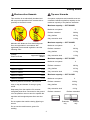
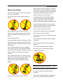
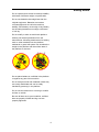
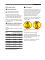
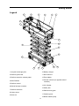
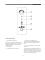
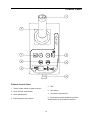
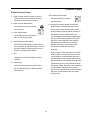
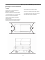
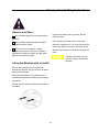
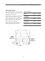
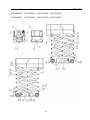
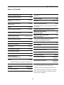
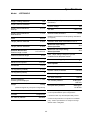
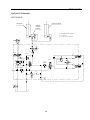
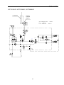
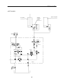
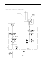
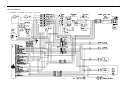
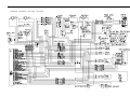
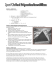
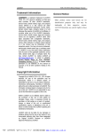
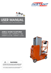
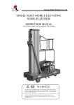
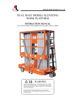
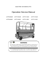
ELECTRIC SCISSOR LIFTS
Operation Service Manual
JCPT0808HD
JCPT1008HD
JCPT1012HD
JCPT1212HD
JCPT0808DC
JCPT1008DC
JCPT1012DC
JCPT1212DC
WARNING
THE MANUFACTURER SHALL NOT BE HELD LIABLE IN CASE OF FAULTS
OR ACCIDENTS DUE TO NEGLIGENCE, INCAPACITY, INSTALLATION BY
UNQUALIFIED TECHNICIANS AND IMPROPER USE OF THE MACHINE.
DO NOT OPERATE THIS MACHINE UNTIL YOU READ AND UNDERSTAND
ALL THE DANGERS, WARNINGS AND CAUTIONS IN THIS MANUAL
Owners, Users and operators:
Important
We appreciate your choice of our machine for
your application. Our number one priority is
user safety, which is best achieved by our joint
efforts. We feel that you make a major
contribution to safety if you, as the equipment
users and operators:
Read, understand and obey these safety rules
and operating instructions before operating this
machine.
Only trained and authorized personnel shall be
permitted to operate this machine. This manual
should be considered a permanent part of your
machine and should remain with the machine
at all times. If you have any questions, please
call DINGLI Machinery.
Contents
1.
Comply with employer, job site and
governmental rules.
2.
Read, understand and follow the
instructions in this and other manuals
supplied with this machine.
3.
Use good safe work practices in a
commonsense way.
4.
0nly have trained / certified operators,
directed by informed and knowledgeable
supervision, running the machine.
Page
Safety Rules
1
Control panel
12
Pre-operation Inspection
15
Maintenance
17
Function Tests
19
Workplace Inspection
24
Operating Instructions
25
Transport and Lifting Instructions
32
Decals
36
Specifications
38
Schematic
46
If there is anything in this manual that is not
clear or which you believe should be added,
please contact us.
Contact us:
i
Safety Rules
Decal Legend
Danger
DINGLI product decals use symbols, color
coding and signal words to identify the
following:
Failure to obey the instructions and
safety rules in this manual will result
in death or serious injury.
Safety alert symbol—used to alert
personnel to potential personal injury hazards.
Obey all safety messages that follow this
symbol to avoid possible injury or death.
Do Not Operate Unless:
√ You learn and practice the principles of safe
Red—used to indicate the
presence of an imminently hazardous situation
which, if not avoided, will result in death or
serious injury.
machine operation contained in this operator's
manual.
1 Avoid hazardous situations.
Know and understand the safety rules
before going on to the next section.
Orange—used to indicate the
presence of a potentially hazardous situation
which, if not avoided, could result in death or
serious injury.
2 Always perform a pre-operation
inspection.
3 Always perform function tests prior to use.
Yellow with safety alert symbolused to indicate the presence of a potentially
hazardous situation which, if not avoided, may
cause minor or moderate injury.
4 Inspect the workplace.
5 Only use the machine as it was intended.
√
You read, understand and obey the
manufacturer's instructions and safety rules—
safety and operator's manuals and machine
decals.
√
Yellow without safety alert
symbol—used to indicate the presence of a
potentially hazardous situation which, if not
avoided, may result in property damage.
You read, understand and obey employer's
safety rules and worksite regulations.
√
You read, understand and obey all
applicable governmental regulations.
√
You are properly trained to safely operate
the machine.
1
Safety Rules
Personal Safety
Intended Use
This machine is intended to be used only to lift
personnel, along with their tools and materials
to an aerial work site.
Fall Protection
Personal fall protection equipment (PFPE) is
not required when operating this machine. If
PFPE is required by job site or employer rules,
the following shall apply:
Safety Sign Maintenance
Replace any missing or damaged safety signs.
Keep operator safety in mind at all times. Use
mild soap and water to clean safety signs. Do
not use solvent-based cleaners because they
may damage the safety sign material.
All PFPE must comply with applicable
governmental regulations, and must be
inspected and used in accordance with the
manufacturer’s instructions.
2
Safety Rules
Electrocution Hazards
Tip-over Hazards
This machine is not electrically insulated and
will not provide protection from contact with or
proximity to electrical current.
Occupants, equipment and materials must not
exceed the maximum platform capacity or the
maximum capacity of the platform extension.
Maximum capacity – JCPT0808HD
Maximum occupants
0 to 300V
50KV to 200KV
4.60
200KV to 350KV
Only platform
267 kg
Only extension deck
113 kg
2
Platform retracted
230 kg
Only platform
117 kg
Only extension deck
113 kg
Maximum capacity – JCPT1012HD
Avoid Contact
3.05
380 kg
Maximum occupants
Minimum Safe
Approach Distance
Meters
300V to 50KV
Platform retracted
Maximum capacity – JCPT1008HD
Maintain safe distances from electrical power
lines and apparatus in accordance with
applicable governmental regulations and the
following chart.
Voltage
Phase to Phase
2
Maximum occupants
2
Platform retracted
450 kg
6.10
Only platform
337 kg
350KV to 500KV
7.62
Only extension deck
113 kg
500KV to 750KV
10.67
Maximum capacity – JCPT1212HD
750KV to 1000KV
13.72
Maximum occupants
Allow for platform movement, electrical line
sway or sag and beware of strong or gusty
winds.
Keep away from the machine if it contacts
energized power lines. Personnel on the ground
or in the platform must not touch or operate the
machine until energized power lines are shut
off.
Platform retracted
320 kg
Only platform
207 kg
Only extension deck
113 kg
Platform retracted
Do not operate the machine during lightning or
storms.
2
Platform extended
Extension
only
Do not use the machine as a ground for
welding.
3
Platform
only
Safety Rules
Maximum capacity – JCPT0808DC
Maximum occupants
2
Platform retracted
380 kg
Only platform
267 kg
Only extension deck
113 kg
Maximum capacity – JCPT1008DC
Maximum occupants
2
Platform retracted
230 kg
Only platform
117 kg
Only extension deck
113 kg
Maximum capacity – JCPT1012DC
Maximum occupants
2
Platform retracted
450 kg
Only platform
337 kg
Only extension deck
113 kg
Maximum capacity – JCPT1212DC
Maximum occupants
2
Platform retracted
320 kg
Only platform
207 kg
Only extension deck
113 kg
Platform retracted
Platform extended
Extension
only
Platform
only
4
Safety Rules
platform that is caught, snagged or otherwise
prevented from normal motion by an adjacent
structure. All personnel must be removed from
the platform before attempting to free the
platform using the ground controls.
Work Area Safety
Do not raise the platform unless the machine is
on a firm, level surface.
Do not drive over 0.8 km/h with the platform
raised.
Use extreme care and slow speeds while
driving the machine in the stowed position
across uneven terrain, debris, unstable or
slippery surfaces and near holes and drop-offs.
Do not drive the machine on or near uneven
terrain, unstable surfaces or other hazardous
conditions with the platform raised.
Do not use the machine as a crane.
Do not place or attach fixed or overhanging
loads to any part of this machine.
Do not depend on the tilt alarm as a level
indicator. The tilt alarm sounds on the chassis
and in the platform when the machine is on a
slope.
Do not push the machine or other objects with
the platform.
If the tilt alarm sounds:
Do not operate the machine with the chassis
trays open.
Lower the platform. Move the machine to a firm,
level surface. If the tilt alarm sounds when the
platform is raised, use extreme caution to lower
the platform.
Do not contact adjacent structures with the
platform
Do not alter or disable the limit switches.
Do not raise the platform when wind speeds
may exceed 12.5 m/s. If wind speeds exceed
12.5 m/s when the platform is raised, lower the
platform and do not continue to operate the
machine.
Do not push off or pull toward any object
outside of the platform.
Do not operate the machine in strong or gusty
winds. Do not increase the surface area of the
platform or the load. Increasing the area
exposed to the wind will decrease machine
stability.
Maximum allowable manual force
400 N
Do not tie the platform to adjacent structures.
Do not place loads outside the platform
perimeter.
Do not alter or disable machine components
that in any way affect safety and stability.
Do not use the platform controls to free a
5
Safety Rules
Do not replace items critical to machine stability
with items of different weight or specification.
Do not use batteries that weigh less than the
original equipment. Batteries are used as
counterweight and are critical to machine
stability. Each battery must weigh 33 kg. Battery
box including batteries must weigh a minimum
of 165 kg.
Do not modify or alter an aerial work platform
without prior written permission from the
manufacturer. Mounting attachments for holding
tools or other materials onto the platform,
toeboards or guard rail system can increase the
weight in the platform and the surface area of
the platform or the load.
Do not place ladders or scaffolds in the platform
or against any part of this machine.
Do not transport tools and materials unless they
are evenly distributed and can be safely
handled by person(s) in the platform.
Do not use the machine on a moving or mobile
surface or vehicle.
Be sure all tires are in good condition, air-filled
tires are properly inflated and lug nuts are
properly tightened.
6
Safety Rules
Work Area Safety
Fall Hazards
The guard rail system provides fall protection. If
occupant(s) of the platform are required to wear
personal fall protection equipment (PFPE) due
to job site or employer rules, PFPE equipment
and its use shall be in accordance with the
PFPE manufacturer’s instructions and
applicable governmental requirements.
Crushing Hazards
Keep hands and limbs out of scissors.
Keep hands clear when folding rails.
Use common sense and planning when
operating the machine with the controller from
the ground. Maintain safe distances between
the operator, the machine and fixed objects.
Do not sit, stand or climb on the platform guard
rails. Maintain a firm footing on the platform
floor at all times.
Maintain a firm grasp on the platform rail when
removing the rail pins. Do not allow the platform
guard rails to fall.
Operation on Slopes Hazards
Do not drive the machine on a slope that
exceeds the slope and side slope rating of the
machine.
Slope rating applies to machines in the stowed
position.
Model
Do not climb down from the platform when
raised.
Maximum
Maximum
slope ratingside slope rating
stowed position stowed position
JCPT0808HD
25% (14°)
25% (14°)
JCPT1008HD
25% (14°)
25% (14°)
JCPT1012HD
25% (14°)
25% (14°)
JCPT1012HD
25% (14°)
25% (14°)
JCPT0808DC
25% (14°)
25% (14°)
JCPT1008DC
25% (14°)
25% (14°)
JCPT1012DC
25% (14°)
25% (14°)
JCPT1012DC
25% (14°)
25% (14°)
Keep the platform floor clear of debris.
Close the entry gate before operating.
Do not operate the machine unless the guard
rails are properly installed and the entry is
secured for operation.
Do not enter or exit the platform unless the
machine is in the stowed position.
Note: Slope rating is subject to ground
conditions and adequate traction.
7
Safety Rules
Collision Hazards
Be aware of limited sight distance and blind
spots when driving or operating.
Limit travel speed according to the condition of
the ground surface, congestion, slope, location
of personnel, and any other factors which may
cause collision.
Be aware of extended platform position(s) when
moving the machine.
Check the work area for overhead obstructions
or other possible hazards.
Be aware of crushing hazards when grasping
the platform guard rail.
Operators must comply with employer, job site
and governmental rules regarding use of
personal protective equipment.
Observe and use color-coded direction arrows
on the platform controls and platform decal
plate for drive and steer functions.
Do not operate a machine in the path of any
crane or moving overhead machinery unless
the controls of the crane have been locked out
and/or precautions have been taken to prevent
any potential collision.
No stunt driving or horseplay while operating a
machine.
Do not lower the platform unless the area below
is clear of personnel and obstructions.
8
Safety Rules
Component Damage Hazards
Do not use any battery or charger greater than
24V to charge the batteries.
Do not use the machine as a ground for
welding.
Explosion and Fire Hazards
Do not operate the machine or charge the
batteries in hazardous locations where
potentially flammable or explosive gases or
particles may be present.
Damaged Machine Hazards
Do not use a damaged or malfunctioning
machine.
Conduct a thorough pre-operation inspection of
the machine and test all functions before each
work shift. Immediately tag and remove from
service a damaged or malfunctioning machine.
Be sure all maintenance has been performed as
specified in this manual and the appropriate
DINGLI service manual.
Be sure all decals are in place and legible.
Be sure the operator’s, safety and
responsibilities manuals are complete, legible
and in the storage container located in the
platform.
Bodily Injury Hazard
Do not operate the machine with a hydraulic oil
or air leak. An air leak or hydraulic leak can
penetrate and/or burn skin.
Improper contact with components under any
cover will cause serious injury. Only trained
maintenance personnel should access
compartments. Access by the operator is only
advised when performing a pre-operation
inspection. All compartments must remain
closed and secured during operation.
9
Safety Rules
Battery Safety
Electrocution/ Burn Hazard
Burn Hazards
Batteries contain acid.
Always wear protective
clothing and eye wear
when working with
batteries.
Connect the battery
charger to a grounded,
AC 3-wire electrical
outlet only.
Inspect daily for
damaged cords, cables
and wires. Replace
damaged items before
operating.
Avoid spilling or
contacting battery acid.
Neutralize battery acid
spills with baking soda
and water.
Avoid electrical shock from contact with battery
terminals. Remove all rings, watches and other
jewelry.
Explosion Hazard
Keep sparks, flames and
lighted tobacco away
from batteries. Batteries
emit explosive gas.
Tip-over Hazard
Do not use batteries that weigh less than the
original equipment. Batteries are used as
counterweight and are critical to machine
stability. Each battery must weigh 33 kg. Battery
tray including batteries must weigh a minimum
of 165 kg.
The battery tray should
remain open during the
entire charging cycle.
Do not contact the
battery terminals or the
cable clamps with tools
that may cause sparks.
Lifting Hazard
Use the appropriate number of people and
proper lifting techniques when lifting batteries.
Component Damage Hazard
Lockout After Each Use
Do not use any battery charger greater than
24V to charge the batteries.
1 Select a safe parking location - firm level
surface, clear of obstruction and traffic.
2 Lower the platform.
3 Turn the key switch to the off position and
remove the key to secure from unauthorized
use.
4 Chock the wheels.
5 Charge the batteries.
10
Safety Rules
Legend
6
5
3
4
1
2
1
7
16
15
8
14
13
9
17
11
10
18
12
1 Lanyard anchorage point
10 Battery charger
2 Platform guard rails
11 Non-steer tire
3 Platform extension release pedal
12 Entry ladder
4 Main Platform
13 Ground controls (on opposite side of
machine)
5 Platform control
14 Lift Cylinder
6 Manual storage container
15 Safety arm
7 Platform extension
16 Platform entry gate
8 Scissor Arms
17 Pothole guard
9 Steer tire
18 Brake release pump
11
GE
NCY
ST
OP
EM ER
Control Panel
1
2
3
4
5
Ground Control Panel
1
4
Red Emergency Stop button
Move the switch up and the platform will raise.
Move the switch down and the platform will
lower.
Push in the red Emergency Stop button to the
off position to stop all functions. Pull out the red
Emergency Stop button to the on position to
operate the machine.
2
Indicator light
3
7 amp breaker for electric circuits
Platform up / down toggle switch
5 Key switch for platform / off / ground control
selection
Turn the key switch to the platform position and
the platform controls will operate. Turn the key
switch to the off position and the machine will
be off. Turn the key switch to the base position
and the ground controls will operate
12
Control Panel
Platform Control Panel
1
Thumb rocker switch for steer functions
2
Drive function select button
3
Drive speed button
4
Red Emergency Stop button
5
LED
6
Horn button
7
Lift function select button
8 Proportional control handle and function
enable switch for lift and drive functions
13
Control Panel
Platform Control Panel
1
2
Thumb rocker switch for steer functions
Press the thumb rocker switch in either
direction to activate steer function.
7 Lift function select button
Drive function select button
8
Press this button to activate
the lift function.
Press this button to activate the
drive function.
3
Lift function: Press and hold the function
enable switch to enable the lift function on
the platform control handle. Move the
control handle in the direction indicated by
the blue arrow and the platform will raise.
Move the control handle in the direction
indicated by the yellow arrow and the
platform will lower. The descent alarm
should sound while the platform is
lowering.
Drive speed button
Press this button to activate the
slow or fast drive function.
4
Red Emergency Stop button
Push in the red Emergency Stop button to
the off position to stop all functions. Pull out
the red Emergency Stop button to the on
position to operate the machine.
5
Drive function: Press and hold the function
enable switch to enable the drive function
on the platform control handle. Move the
control handle in the direction indicated by
the blue arrow on the control panel and the
machine will move in the direction that the
blue arrow points. Move the control handle
in the direction indicated by the yellow
arrow on the control panel and the machine
will move in the direction that the yellow
arrow points.
LED
Diagnostic read out and battery charge
indicator.
6
Proportional control handle and function
enable switch for lift and drive functions
Horn Button
Push the horn button and the horn will
sound. Release the horn button and the
horn will stop.
14
Pre-operation Inspection
Fundamentals
Do Not Operate Unless:
√
It is the responsibility of the operator to perform
a pre-operation inspection and routine
maintenance.
You learn and practice the principles of
safe machine operation contained in this
operator's manual.
The pre-operation inspection is a visual
inspection performed by the operator prior to
each work shift. The inspection is designed to
discover if anything is apparently wrong with a
machine before the operator performs the
function tests.
1 Avoid hazardous situations.
2 Always perform a pre-operation
inspection.
Know and understand the pre-operation
inspection before going on to the next
section.
The pre-operation inspection also serves to
determine if routine maintenance procedures
are required. Only routine maintenance items
specified in this manual may be performed by
the operator.
3 Always perform function tests prior to use.
4 Inspect the workplace.
5 Only use the machine as it was intended.
Refer to the list on the next page and check
each of the items.
If damage or any unauthorized variation from
factory delivered condition is discovered, the
machine must be tagged and removed from
service.
Repairs to the machine may only be made by a
qualified service technician, according to the
manufacturer's specifications. After repairs are
completed, the operator must perform a
pre-operation inspection again before going on
to the function tests.
Scheduled maintenance inspections shall be
performed by qualified service technicians,
according to the manufacturer's specifications
and the requirements listed in the
responsibilities manual.
15
Pre-operation Inspection
Pre-operation Inspection
□ Platform control joystick
□ Be sure that the operator’s, safety and
□ Brake release components
responsibilities manuals are complete, legible
and in the storage container located in the
platform.
Check entire machine for:
□ Cracks in welds or structural components
□ Dents or damage to machine
□ Be sure that all decals are legible and in
place. See Decals section.
□ Be sure that all structural and other critical
□ Check for hydraulic oil leaks and proper oil
components are present and all associated
fasteners and pins are in place and properly
tightened
level. Add oil if needed. See Maintenance
section.
□ Be sure side rails are installed and rail pins
□ Check for battery fluid leaks and proper fluid
and bolts are fastened.
level. Add distilled water if needed. See
Maintenance section.
□ Be sure that the chassis trays are closed
Check the following components or areas for
damage, improperly installed or missing parts
and unauthorized modifications:
and latched and the batteries are properly
connected.
Note: If the platform must be raised to inspect
the machine, make sure the safety arm is in
place. See Operating Instructions section.
□ Electrical components, wiring and
electrical cables
□Hydraulic hoses, fittings, cylinders and
manifolds
□ Battery pack and connections
□ Drive motors
□ Wear pads
□ Tires and wheels
□ Ground strap
□ Limit switches, alarms and horn
□ Nuts, bolts and other fasteners
□ Platform overload components
□ Platform entry gate
□ Beacon and alarms (if equipped)
□ Safety arm
□ Platform extension(s)
□ Scissor pins and retaining fasteners
16
Maintenance
Observe and Obey:
Check the Batteries
□ Only routine maintenance items specified in
this manual shall be performed by the operator.
Proper battery condition is essential to
operational safety. Improper fluid levels or
damaged cables and connections can result in
component damage and hazardous conditions.
□ Scheduled maintenance inspections shall be
completed by qualified service technicians,
according to the manufacturer's specifications
and the requirements specified in the
responsibilities manual.
Electrocution hazard
Maintenance Symbols Legend
Contact with hot or live circuits may result in
death or serious injury. Remove all rings,
watches and other jewelry.
The following symbols have
been used in this manual to help communicate
the intent of the instructions. When one or more
of the symbols appear at the beginning of a
maintenance procedure, it conveys the
meaning below.
Bodily injury hazard
Batteries contain acid. Avoid spilling or
contacting battery acid. Neutralize battery acid
spills with baking soda and water.
Indicates that tools will be required to
perform this procedure.
Indicates that new parts will be required
to perform this procedure.
17
1
Put on protective clothing and eye wear.
2
Be sure that the battery cable
connections are tight and free of
corrosion.
3
Be sure that the battery hold-down bars
are secure.
4
Remove the battery vent caps.
5
Check the battery acid level. If needed,
replenish with distilled water to the bottom
of the battery fill tube. Do not overfill.
6
Install the vent caps.
Maintenance
Check the Hydraulic Oil Level
Scheduled Maintenance
Maintenance performed quarterly, annually and
every two years must be completed by a person
trained and qualified to perform maintenance on
this machine according to the procedures found
in the service manual for this machine.
Maintaining the hydraulic oil at the proper level
is essential to machine operation. Improper
hydraulic oil levels can damage hydraulic
components. Daily checks allow the inspector to
identify changes in oil level that might indicate
the presence of hydraulic system problems.
Machines that have been out of service for
more than three months must receive the
quarterly inspection before they are put back
into service.
Perform this procedure with the
platform in the stowed position and the engine
off.
1
Visually inspect the sight gauge located on
the side of the hydraulic oil tank.
☉Result: The hydraulic oil level should be
within the Lower and Full of the sight gauge.
2
Add oil if necessary. Do not overfill.
Hydraulic oil specifications
-18℃~-5℃
-18℃~99℃
10W
10W-20,10W-30
18
Function Tests
Fundamentals
Do Not Operate Unless:
√
The function tests are designed to discover any
malfunctions before the machine is put into
service.
You learn and practice the principles of safe
machine operation contained in this operator's
manual.
The operator must follow the step-by-step
instructions to test all machine functions.
1 Avoid hazardous situations.
A malfunctioning machine must never be used.
If malfunctions are discovered, the machine
must be tagged and removed from service.
Repairs to the machine may only be made by a
qualified service technician, according to the
manufacturer's specifications.
2 Always perform a pre-operation inspection.
3 Always perform function tests prior to
use.
Know and understand the function tests
before going on to the next section.
After repairs are completed, the operator must
perform a pre-operation inspection and function
tests again before putting the machine into
service.
4 Inspect the workplace.
5 Only use the machine as it was intended.
19
Function Tests
1
2
Select a test area that is firm, level and free
of obstruction.
☉ Result: The platform should raise.
12 Move down and hold the platform down
switch.
Be sure the battery pack is connected.
At the Ground Controls
☉ Result: The platform should lower then stop
at the height is 2.1 m. The descent alarm
should sound while the platform is lowering.
3
Pull out the platform and ground red
Emergency Stop buttons to the on position.
4
Turn the key switch to ground control.
13 Move down and hold the platform down
switch.
5
Observe the diagnostic LED readout on the
platform controls.
☉Result: The platform should lower to end. The
descent alarm should sound while the
platform is lowering.
☉Result: The LED should look
like the picture at right.
Test the Emergency Lowering
Test Emergency Stop
6
14 Activate the up function and raise the
platform approximately 60 cm.
Push in the ground red Emergency Stop
button to the off position.
15 Pull the emergency lowering knob located
the ground control side .
☉ Result: No functions should operate.
7
☉Result: The platform should lower. The
descent alarm will not sound.
Pull out the red Emergency Stop button to
the on position.
16 Turn the key switch to platform control.
Test Up/Down Functions
The audible warnings on this machine and the
standard horn all come from the same central
alarm. The horn is a constant tone. The descent
alarm sounds at 60 beeps per minute. The
alarm that goes off when the pothole guards
have not deployed sounds at 300 beeps per
minute. The alarm that goes off when the
machine is not level sounds at 600 beeps per
minute. An optional automotive-style horn is
also available.
8
Turn the key switch to off or platform
position.
9
Move up and hold the platform switch.
At the Platform Controls
Test Emergency Stop
17 Push in the platform red Emergency Stop
button to the off position.
☉ Result: No functions should operate.
18 Pull the red Emergency Stop button out to
the on position.
☉ Result: The LED indicator light should come
☉ Result: No function should operate.
on.
Test the Horn
10 Turn the key switch to ground control
position.
11
19 Push the horn button.
Move up and hold the platform up switch.
☉ Result: The horn should sound.
20
Function Tests
Test Function Enable and Up/Down
Functions
Test the Steering
Note: When performing the steer and drive
function tests, stand in the platform facing the
steer end of the machine.
20 Do not hold the function enable switch on
the control handle.
27 Press the drive function select switch.
21 Slowly move the control handle in the
direction indicated by the blue arrow, then in
the direction indicated by the yellow arrow.
28 Press and hold the function enable switch
on the control handle.
☉ Result: No functions should operate.
29 Depress the thumb rocker switch on top of
the control handle in the direction identified
by the blue left arrow on the control panel.
22 Press the lift function select button.
23 Press and hold the function enable switch
on the control handle.
☉ Result: The steer wheels should turn in the
direction that the blue left arrow points on
the control panel.
24 Slowly move the control handle in the
direction indicated by the blue arrow.
30 Depress the thumb rocker switch in the
direction identified by the white right arrow
on the control panel.
☉ Result: The platform should raise. The
pothole guards should deploy.
25 Release the control handle.
☉ Result: The steer wheels should turn in the
direction that the white right arrow points on
the control panel.
☉ Result: The platform should stop raising.
26 Press and hold the function enable switch.
Slowly move the control handle in the
direction indicated by the yellow arrow.
☉Result: The platform should lower. The
descent alarm should sound while the platform
is lowering.
21
Function Tests
Test Drive and Braking
Test Limited Drive Speed
31 Press and hold the function enable switch
on the control handle.
35 Press and hold the lift function enable
switch. Raise the platform approximately
2.1 m) from the ground.
32 Slowly move the control handle in the
direction indicated by the blue up arrow on
the control panel until the machine begins to
move, then return the handle to the center
position.
☉ Result: The pothole guards should deploy,
36 Press and hold the function enable switch
on the control handle.
37 Slowly move the control handle to the full
drive position.
☉ Result: The machine should move in the
direction that the blue up arrow points on the
control panel, then come to an abrupt stop.
☉ Result: The maximum achievable drive
speed with the platform raised should not
exceed 20 cm/s.
33 Press and hold the function enable switch
on the control handle.
If the drive speed with the platform raised
exceeds 20 cm/s, immediately tag and
remove the machine from service.
34 Slowly move the control handle in the
direction indicated by the yellow down arrow
on the control panel until the machine
begins to move, then return the handle to
the center position.
☉ Result: The machine should move in the
direction that the yellow down arrow points
on the control panel, then come to an abrupt
stop.
Note: The brakes must be able to hold the
machine on any slope it is able to climb.
22
Function Tests
Test the Tilt Sensor Operation
Test the Pothole Guards
Note: Perform this test from the ground with the
platform controller. Do not stand in the platform.
Note : The pothole guards should automatically
deploy when the platform is raised . The pothole
guards activate another limit switch which
allows the machine to continue to function . If
the pothole guards do not deploy , an alarm
sounds and the machine will not drive.
38 Fully lower the platform.
39 Place a 2x4 or similar piece of wood under
both wheels on one side and drive the
machine up onto them.
43 Raise the platform .
40 Raise the platform at least 2.1 m.
☉ Result : When the platform is raised 2 m from
the ground , the pothole guards should
deploy .
☉ Result: The platform should stop and the tilt
alarm will sound at 600 beeps per minute..
41 Move the drive control handle in the
direction indicated by the blue up arrow,
then move the drive control handle in the
direction indicated by the white down arrow.
44 Press on the pothole guards on one side ,
and then the other .
☉ Result: The drive function should not work in
45 Lower the platform .
☉ Result : The pothole guards should not
move .
either direction.
☉ Result : The pothole guards should return to
the stowed position .
42 Lower the platform and drive the machine
off the block.
46 Place a 2x4 or similar piece of wood under
a pothole guard . Raise the platform .
☉ Result : Before the platform is raised 2 m
from the ground , an alarm should sound
and the drive function should not Work .
47 Lower the platform and remove the 2x4
wood block.
23
Workplace Inspection
Fundamentals
Do Not Operate Unless:
√
The workplace inspection helps the operator
determine if the workplace is suitable for safe
machine operation. It should be performed by
the operator prior to moving the machine to the
workplace.
You learn and practice the principles of safe
machine operation contained in this operator's
manual.
1 Avoid hazardous situations.
It is the operator's responsibility to read and
remember the workplace hazards, then watch
for and avoid them while moving, setting up and
operating the machine.
2 Always perform a pre-operation inspection.
3 Always perform function tests prior to use.
4 Inspect the workplace.
Know and understand the workplace
inspection before going on to the next
section.
Workplace Inspection
5 Only use the machine as it was intended.
Be aware of and avoid the following hazardous
situations:
- Drop-offs or holes
- Bumps, floor obstructions or debris
- Sloped surfaces
- Unstable or slippery surfaces
- Overhead obstructions and high voltage
conductors
- Hazardous locations
- Inadequate surface support to withstand all
load forces imposed by the machine
- Wind and weather conditions
- The presence of unauthorized personnel
- Other possible unsafe conditions
24
Operating Instructions
Fundamentals
The Operating Instructions section provides
instructions for each aspect of machine
operation.
Do Not Operate Unless:
√
It is the operator's responsibility to follow all the
safety rules and instructions in the operator's,
safety and responsibilities manuals.
You learn and practice the principles of
safe machine operation contained in this
operator's manual.
Using the machine for anything other than lifting
personnel, along with their tools and materials,
to an aerial work site is unsafe and dangerous.
1 Avoid hazardous situations.
2 Always perform a pre-operation inspection.
Only trained and authorized personnel should
be permitted to operate a machine. If more than
one operator is expected to use a machine at
different times in the same work shift, they must
all be qualified operators and are all expected to
follow all safety rules and instructions in the
operator's, safety and responsibilities manuals.
That means every new operator should perform
a pre-operation inspection, function tests, and a
workplace inspection before using the machine.
3 Always perform function tests prior to use.
4 Inspect the workplace.
5 Only use the machine as it was intended.
25
Operating Instructions
Emergency Stop
Operation from Platform
Push in the red Emergency Stop button to the
off position at the ground controls or the
platform controls to stop all machine functions.
1
Turn the key switch to platform control.
2
Pull out the ground and platform red
Emergency Stop buttons to the on position.
3
Be sure the battery pack is connected
before operating the machine.
Repair any function that operates when either
red Emergency Stop button is pushed in.
Emergency Lowering
To Position Platform
1 Pull the emergency lowering knob.
1
Press the lift function select button.
Operation from Ground
2
Press and hold the lift function enable
switch on the control handle.
3
Move the control handle according to the
markings on the control panel.
1
Turn the key switch to ground control.
2
Pull out both ground and platform red
Emergency Stop buttons to the on position.
3
Be sure the battery pack is connected
before operating the machine.
To Steer
To Position Platform
1
Move the up/down toggle switch according
to the markings on the control panel..
1
Press the drive function select button.
2
Press and hold the function enable switch
on the control handle.
3
Turn the steer wheels with the thumb rocker
switch located on the top of the control
handle.
Drive and steer functions are not available from
the ground controls.
To Drive
1
Press the drive function select button.
2
Press and hold the function enable switch
on the control handle.
3
Increase speed: Slowly move the control
handle off center.
Decrease speed: Slowly move the control
handle toward center.
Stop: Return the control handle to center or
release the function enable switch.
Use the color-coded direction arrows on the
platform controls and on the platform to identify
the direction the machine will travel.
Machine travel speed is restricted when the
26
Operating Instructions
platform is raised.
wood to the ground.
Battery condition will affect machine
performance. Machine drive speed and function
speed will drop when the battery level indicator
is flashing.
Divide the tape measure distance (rise) by the
length of the piece of wood (run) and multiply by
100.
Example:
To reduce drive speed
Run = 3.6 m
The drive controls can operate in two different
drive speed modes. When the drive speed
button light is on, slow drive speed mode is
active. When the button light is off, fast drive
speed mode is active.
Rise = 0.3 m
0.3 m ÷ 3.6 m = 0.083 x 100 = 8.3%
If the slope exceeds the maximum slope or side
slope rating, the machine must be winched or
transported up or down the slope. See
Transport and Lifting section.
Press the drive speed button to select the
desired drive speed.
Driving on a slope
Determine the slope and side slope ratings for
the machine and determine the slope grade.
S0608, S0808, S0812, S1012 Maximum slope
rating, stowed position 25% , Maximum side
slope rating, stowed position 25%
Note: Slope rating is subject to ground
conditions and adequate traction.
Press the drive speed button to the fast drive
speed mode.
To determine the slope grade
Measure the slope with a digital inclinometer
OR use the following procedure.
You will need:
Carpenter’s level
straight piece of wood, at least 1 m long
tape measure
Lay the piece of wood on the slope.
At the downhill end, lay the level on the top
edge of the piece of wood and lift the end until
the piece of wood is level.
While holding the piece of wood level, measure
the distance from the bottom of the piece of
27
Operating Instructions
Operation from Ground with
Controller
How to Fold Down the Guardrails
The platform railing system consists of three
fold down rail section for the extension deck and
three section for the main deck. All sections are
held in place by four wire lock pins.
Maintain safe distances between operator,
machine and fixed objects.
Be aware of the direction the machine will travel
when using the controller.
1.
Fully lower the platform and retract the
platform extension.
2.
Remove the platform controls.
3.
From inside the platform, remove the two
front extension deck wire lock pins.
4.
Fold down the front rail assembly. Keep
hands clear of pinch points.
5.
Replace the two removed pins back into
each side rail bracket.
6.
2 Rotate the safety arm away from the
machine and let it hang down.
Fold down the extension platform right rail
assembly. Keep hands clear of pinch
points.
7.
3 Lower the platform until the safety arm rests
securely on the link. Keep clear of the safety
arm when lowering the platform.
Fold down the extension platform left rail
assembly. Keep hands clear of pinch
points.
8.
Don’t engage the safety arm
unless unload the platform.
Carefully open the gate and move to the
rear step or the ground.
9.
From the rear step or from the ground,
remove the right rear main deck wire lock
pins.
Battery Level Indicator
Full
Low
Use the LED diagnostic readout to determine
the battery level.
How to use the Safety Arm
1 Raise the platform approximately 3 m from
the ground.
10. Fold down the right rail assembly. Keep
hands clear of pinch points.
11. Replace the removed pin back into rear rail
bracket.
12. Remove the left rear main deck wire lock
pins.
13. Fold down the left rail assembly. Keep
hands clear of pinch points.
14. Replace the removed pin back into rear rail
bracket.
28
Operating Instructions
How to Raise the Guardrails
To Extend and Retract Platform
Follow the fold down instructions but in reverse
order.
1.
Press the platform lock pin pedal on the
extension deck by foot.
2.
Push the platform extension guardrail to
extend the platform to the desired position.
Do not stand on the platform extension
while trying to extend it.
29
Operating Instructions
Error indicator readout
If the LED diagnostic readout
displays an error code, such as LL,
push in and pull out the red
Emergency Stop button to reset the system.
Fault Codes
Code
Description
--
Condition Normal
01
System initialization error
02
System communication error
03
Invalid option Setting
12
Chassis Up/Down
Power-up
18
Pothole Guard Failure
31
Pressure Sensor Fault
32
Angle Sensor Fault
34
Mode Switch Failure
42
43
46
47
Switch
ON
at
Platform Left Turn Switch ON at
Power-up
Platform Right Turn Switch ON at
Power-up
Platform Joystick Enable Switch ON at
Power-up
Platform Joystick not in neutral at
power-up
52
Drive Forward Coil Fault
53
Drive Reverse Coil Fault
54
Lift Up Coil Fault
55
Lift Down Coil Fault
56
Right Turn Coil Fault
57
Left Turn Coil Fault
58
Brake Fault
59
Low Speed Coil Fault
61
Motor Controller Current Sensor Fault
62
Motor Controller Hardware Failsafe
Fault
63
Motor Controller Motor Output Fault
64
Motor Controller SRO Fault
65
Motor Controller Throttle Fault
66
Motor Controller Emergency Reverse
Fault
67
Motor Controller HPD Fault
68
Low Voltage Fault
71
Motor Controller Main Contactor Fault
72
Motor Controller Over Voltage Fault
73
Motor Controller Thermal Cutback
Fault
74
Motor Controller Motor Fault
80
Over 80% Load
90
Over 90% Load
99
Over 100% Load
OL
Overloaded Platform
LL
Machine Tilted beyond safe limits
For more information, please consult the
appropriate Dingli Service Manual.
30
Operating Instructions
Standard Batteries
3.
Remove the battery vent caps and check
the battery acid level. If necessary, add
only enough distilled water to cover the
plates. Do not overfill prior to the charge
cycle.
Observe and Obey:
4.
Replace the battery vent caps.
√
5.
Connect the battery charger to a grounded
AC circuit.
6.
The charger will indicate when the battery
is fully charged.
7.
Check the battery acid level when the
charging cycle is complete. Replenish with
distilled water to the bottom of the fill tube.
Do not overfill.
Battery and Charger Instructions
Do not use an external charger or booster
battery.
√
Charge the battery in a well-ventilated area.
√
Use proper AC input voltage for charging as
indicated on the charger.
√
Use only a Dingli authorized battery and
charger.
Dry Battery Filling and
Charging Instructions
To Charge Battery
1.
2.
Be sure the batteries are connected before
charging the batteries.
Open the battery compartment. The
compartment should remain open for the
entire charging cycle.
Connect the battery charger to a grounded
AC circuit.
4.
The charger will indicate when the battery
is fully charged.
Remove the battery vent caps and
permanently remove the plastic seal from
the battery vent openings.
2.
Fill each cell with battery acid (electrolyte)
until the level is sufficient to cover the
plates.
Do not fill to maximum level until the battery
charge cycle is complete. Overfilling can cause
the battery acid to overflow during charging.
Neutralize battery acid spills with baking soda
and water.
Maintenance - free batteries
3.
1.
31
3.
Install the battery vent caps.
4.
Charge the battery.
5.
Check the battery acid level when the
charging cycle is complete. Replenish with
distilled water to the bottom of the fill tube.
Do not overfill.
Transport and Lifting Instructions
Brake Release Operation
For the Hydraulic Motor Drive Model
Observe and Obey:
√
applied to control the movement of the machine
when lifting it with a crane or forklift.
√
2.
Be sure the winch line is properly secured
to the drive chassis tie points and the path
is clear of all obstructions.
3.
Push in the black brake release knob to
open the brake valve.
4.
Pump the red brake release pump knob.
The transport vehicle must be parked on a
level surface.
√
Chock the wheels to prevent the machine
from rolling.
Only qualified aerial lift operators should
move the machine on or off the truck.
√
1.
Common sense and planning must be
The transport vehicle must be secured to
prevent rolling while the machine is being
loaded.
For the DC Motor Drive Model
√
1.
Be sure the vehicle capacity, loading
surfaces and chains or straps are sufficient to
withstand the machine weight. See the serial
label for the machine weight.
√
2.
The machine must be on a level surface or
3.
secured before releasing the brakes.
√
Do not allow the rails to fall when the snap
pins are removed. Maintain a firm grasp on the
rails when the rails are lowered.
√
4.
Do not drive the machine on a slope that
exceeds the slope or side slope rating. See
Driving on a Slope in the Operating Instructions
section.
√
Chock the wheels to prevent the machine
from rolling.
Pull out the red Emergency Stop button on
both the ground and platform controls to
the on position.
Press and hold lift switch to “down” position
in ground control, meanwhile turn on the
key switch to the "Ground" position. The
brake will be released after Alarm alerts.
If you want to close the brake release, just
turn off the key switch in “ground” position.
Towing the Hydraulic Drive Model is not
recommended. If the machine must be towed,
do not exceed 3.5 km/h.
Towing the DC Motor Drive Model is not
recommended. If the machine must be towed,
do not exceed 4.1 km/h.
If the slope of the transport vehicle bed
exceeds the maximum slope rating, the
machine must be loaded and unloaded using a
winch as described.
32
Transport and Lifting Instructions
Securing to Truck or Trailer for
Transit
Use a minimum of 2 chains or straps.
Always chock the machine wheels in
preparation for transport.
Use chains or straps of ample load capacity.
Retract and secure the extension deck(s).
If the railings have been folded down, secure
them with straps before transporting.
Turn the key switch to the off position and
remove the key before transporting.
Inspect the entire machine for loose or
unsecured items.
Use the tie-down points on the chassis for
anchoring down to the transport surface.
33
Transport and Lifting Instructions
Observe and Obey:
√
Position the forklift forks in position with the
forklift pockets.
Only qualified riggers should rig and lift the
machine.
√
Drive forward to the full extent of the forks.
Only qualified forklift operators should lift
Raise the machine 6 in / 15 cm and then tilt the
forks back slightly to keep the machine secure.
the machine with a forklift.
√
Be sure the crane capacity, loading
Be sure the machine is level when lowering the
forks.
surfaces and straps or lines are sufficient to
withstand the machine weight. See the serial
plate for the machine weight.
Lifting the machine from the
side can result in component
damage.
Lifting the Machine with a Forklift
Be sure the extension deck, controls and
component trays are secure. Remove all loose
items on the machine.
Fully lower the platform. The platform must
remain lowered during all loading and transport
procedures.
Use the forklift pockets located on both sides of
the ladder.
34
Transport and Lifting Instructions
Lifting Instructions
Center of gravity
Fully lower the platform. Be sure the extension
decks, controls and covers are secure. Remove
all loose items on the machine.
Model
Determine the center of gravity of your machine
using the table and the picture on this page.
Attach the rigging only to the designated lifting
points on the machine. There are two lifting
points on each end of the machine.
Adjust the rigging to prevent damage to the
machine and to keep the machine level.
35
X Axis
Y Axis
JCPT0808HD
JCPT0808DC
90.5 cm
56.5cm
JCPT1008HD
JCPT1008DC
80.6cm
57.6cm
JCPT1012HD
JCPT1012DC
89cm
64.4cm
JCPT1212HD
JCPT1212DC
83cm
68.2cm
Decals
Decal Inspection
Use the pictures on the next page to verify that all decals are legible and in place.
Below is a numerical list with quantities and descriptions.
No.
Part No.
Description
Qty.
1
Notice - Manual Box
1
2
IPAF Decal
1
3
CE Decal
1
4
Logo Decal
1
5
Danger - Safety Rules
1
6
Danger -Tip-over Hazard
1
7
Danger -Tilt Operation instruction
1
8
Capacity Decal
1
9
Series Name Decal
2
10
Model Name Decal
2
11
Notice - Side Force
2
12
Safety Arm
2
13
Danger- Crush Hazard
2
14
Warning- Crush Hazard
2
15
Crane Hole Decal
4
16
Tie Hole Decal
4
17
Warning- Pre Operation
2
18
Danger- Explosion/burn Hazard
2
19
Nameplate
1
20
Emergency Lower
1
21
Warning- Battery Charging
1
22
Warning- Crush Hazard
1
23
Forklift Pocket
2
24
Harness Decal
4
25
Notice- Keyswitch
1
36
Decals
JCPT0808HD JCPT1008HD
JCPT1012HD JCPT1212HD
JCPT0808DC JCPT1008DC
JCPT1012DC JCPT1212DC
37
Specifications
Model: JCPT0808HD
Height, working maximum
8m
Height, platform maximum
6m
Maximum hydraulic pressure
(functions)
241.3 bar
System voltage
24V
Height, stowed maximum
Rails up
2.21 m
Height, stowed maximum
Rails lowered
1.75 m
Width
0.81 m
Length, platform retracted
2.48 m
Vibration value does not exceed 2 .5m / s2
Length, platform extended
3.38 m
Maximum slope rating ,
Stowed position
25%
Maximum side slope rating
Stowed position
25%
Platform dimensions
Platform length x width
Tire size
Airborne noise emissions
Maximum load capacity
Note : Slope rating is subject to ground
conditions and adequate traction .
0.9 m
380 kg
Maximum wind speed
Maximum working slope
12.5 m/s
Wheelbase
1.87 m
Turning radius (outside)
2.19 m
Turning radius (inside)
1.9 cm
Weight
1950kg
Controls
AC outlet in platform
3.5 km/h
Platform raised, maximum
0.8 km/h
Tire load, maximum
(Machine weights vary with option configurations)
Power source
Stowed, maximum
Floor loading information
10cm
Ground clearance
Pothole guards deployed
3°
Drive speeds
0
Ground clearance
<70 dB
Maximum sound level at normal operating workstations
(A-weighted)
2.27 x 0.81 m
Platform extension length
φ381×127
4 Batteries , 6V 210AH
1000 kg
Tire contact pressure
6.96 kg/cm2
682 kPa
Occupied floor pressure
1060 kg/m2
10.39 kPa
Note: Floor loading information is approximate and does
not incorporate different option configurations.
Proportional
It should be used only with adequate safety factors.
Standard
Continuous improvement of our products is a DINGLI
policy. Product specifications are subject to change
without notice or obligation.
38
Specifications
Model: JCPT1008HD
Height, working maximum
10 m
Height, platform maximum
8m
Maximum hydraulic pressure
(functions)
241.3 bar
System voltage
24V
Height, stowed maximum
Rails up
2.33 m
Height, stowed maximum
Rails lowered
1.88 m
Width
0.81 m
Length, platform retracted
2.48 m
Vibration value does not exceed 2 .5m / s2
Length, platform extended
3.38 m
Maximum slope rating ,
Stowed position
25%
Maximum side slope rating
Stowed position
25%
Platform dimensions
Platform length x width
Tire size
Airborne noise emissions
Maximum load capacity
Note : Slope rating is subject to ground
conditions and adequate traction .
0.9 m
230 kg
Maximum wind speed
Maximum working slope
12.5 m/s
Wheelbase
1.87 m
Turning radius (outside)
2.19 m
Turning radius (inside)
1.9 cm
Weight
2100kg
Controls
AC outlet in platform
3.5 km/h
Platform raised, maximum
0.8 km/h
Tire load, maximum
(Machine weights vary with option configurations)
Power source
Stowed, maximum
Floor loading information
10cm
Ground clearance
Pothole guards deployed
3°
Drive speeds
0
Ground clearance
<70 dB
Maximum sound level at normal operating workstations
(A-weighted)
2.27 x 0.81 m
Platform extension length
φ381×127
4 Batteries , 6V 210AH
1000 kg
Tire contact pressure
6.96 kg/cm2
682 kPa
Occupied floor pressure
1142 kg/m2
11.19 kPa
Note: Floor loading information is approximate and does
not incorporate different option configurations.
Proportional
It should be used only with adequate safety factors.
Standard
Continuous improvement of our products is a DINGLI
policy. Product specifications are subject to change
without notice or obligation.
39
Specifications
Model: JCPT1012HD
Height, working maximum
10 m
Height, platform maximum
8m
Maximum hydraulic pressure
(functions)
241.3 bar
System voltage
24V
Height, stowed maximum
Rails up
2.33 m
Height, stowed maximum
Rails lowered
1.86 m
Width
1.15 m
Length, platform retracted
2.48 m
Vibration value does not exceed 2 .5m / s2
Length, platform extended
3.38 m
Maximum slope rating ,
Stowed position
25%
Maximum side slope rating
Stowed position
25%
Platform dimensions
Platform length x width
Tire size
Airborne noise emissions
Maximum load capacity
Note : Slope rating is subject to ground
conditions and adequate traction .
0.9 m
450 kg
Maximum wind speed
Maximum working slope
12.5 m/s
Wheelbase
1.87 m
Turning radius (outside)
2.33 m
Turning radius (inside)
1.9 cm
Weight
2300kg
Controls
AC outlet in platform
3.5 km/h
Platform raised, maximum
0.8 km/h
Tire load, maximum
Tire contact pressure
Occupied floor pressure
(Machine weights vary with option configurations)
Power source
Stowed, maximum
Floor loading information
10cm
Ground clearance
Pothole guards deployed
3°
Drive speeds
0
Ground clearance
<70 dB
Maximum sound level at normal operating workstations
(A-weighted)
2.27 x 1.12 m
Platform extension length
φ381×127
4 Batteries , 6V 210AH
1000 kg
7.09 kg/cm2
694 kPa
881 kg/m2
8.63 kPa
Note: Floor loading information is approximate and does
not incorporate different option configurations.
Proportional
It should be used only with adequate safety factors.
Standard
Continuous improvement of our products is a DINGLI
policy. Product specifications are subject to change
without notice or obligation.
40
Specifications
Model: JCPT1212HD
Height, working maximum
12 m
Height, platform maximum
10 m
Maximum hydraulic pressure
(functions)
241.3 bar
System voltage
24V
Height, stowed maximum
Rails up
2.46 m
Height, stowed maximum
Rails lowered
1.99 m
Width
1.15 m
Length, platform retracted
2.48 m
Vibration value does not exceed 2 .5m / s2
Length, platform extended
3.38 m
Maximum slope rating ,
Stowed position
25%
Maximum side slope rating
Stowed position
25%
Platform dimensions
Platform length x width
Tire size
Airborne noise emissions
Maximum load capacity
Note : Slope rating is subject to ground
conditions and adequate traction .
0.9 m
320 kg
Maximum wind speed
Maximum working slope
12.5 m/s
Wheelbase
1.87 m
Turning radius (outside)
2.33 m
Turning radius (inside)
1.9 cm
Weight
2730kg
Controls
AC outlet in platform
3.5 km/h
Platform raised, maximum
0.8 km/h
Tire load, maximum
(Machine weights vary with option configurations)
Power source
Stowed, maximum
Floor loading information
10cm
Ground clearance
Pothole guards deployed
3°
Drive speeds
0
Ground clearance
<70 dB
Maximum sound level at normal operating workstations
(A-weighted)
2.27 x 1.12 m
Platform extension length
φ381×127
4 Batteries , 6V 210AH
1000 kg
Tire contact pressure
7.44 kg/cm2
729 kPa
Occupied floor pressure
1045 kg/m2
10.25 kPa
Note: Floor loading information is approximate and does
not incorporate different option configurations.
Proportional
It should be used only with adequate safety factors.
Standard
Continuous improvement of our products is a DINGLI
policy. Product specifications are subject to change
without notice or obligation.
41
Specifications
Model:
JCPT0808DC
Height, working maximum
8m
Height, platform maximum
6m
Maximum hydraulic pressure
(functions)
241.3 bar
System voltage
24V
Height, stowed maximum
Rails up
2.21 m
Height, stowed maximum
Rails lowered
1.75 m
Width
0.81 m
Length, platform retracted
2.48 m
Vibration value does not exceed 2 .5m / s2
Length, platform extended
3.38 m
Maximum slope rating ,
Stowed position
25%
Maximum side slope rating
Stowed position
25%
Platform dimensions
Platform length x width
Tire size
Airborne noise emissions
Maximum load capacity
Note : Slope rating is subject to ground
conditions and adequate traction .
0.9 m
380 kg
Maximum wind speed
Maximum working slope
12.5 m/s
Wheelbase
1.87 m
Turning radius (outside)
2.19 m
Turning radius (inside)
1.9 cm
Weight
1950kg
Controls
AC outlet in platform
5.0 km/h
Platform raised, maximum
0.8 km/h
Tire load, maximum
(Machine weights vary with option configurations)
Power source
Stowed, maximum
Floor loading information
10cm
Ground clearance
Pothole guards deployed
3°
Drive speeds
0
Ground clearance
<70 dB
Maximum sound level at normal operating workstations
(A-weighted)
2.27 x 0.81 m
Platform extension length
φ381×127
4 Batteries , 6V 210AH
1000 kg
Tire contact pressure
6.96 kg/cm2
682 kPa
Occupied floor pressure
1060 kg/m2
10.39 kPa
Note: Floor loading information is approximate and does
not incorporate different option configurations.
Proportional
It should be used only with adequate safety factors.
Standard
Continuous improvement of our products is a DINGLI
policy. Product specifications are subject to change
without notice or obligation.
42
Specifications
Model: JCPT1008DC
Height, working maximum
10 m
Height, platform maximum
8m
Maximum hydraulic pressure
(functions)
241.3 bar
System voltage
24V
Height, stowed maximum
Rails up
2.33 m
Height, stowed maximum
Rails lowered
1.88 m
Width
0.81 m
Length, platform retracted
2.48 m
Vibration value does not exceed 2 .5m / s2
Length, platform extended
3.38 m
Maximum slope rating ,
Stowed position
25%
Maximum side slope rating
Stowed position
25%
Platform dimensions
Platform length x width
Tire size
Airborne noise emissions
Maximum load capacity
Note : Slope rating is subject to ground
conditions and adequate traction .
0.9 m
230 kg
Maximum wind speed
Maximum working slope
12.5 m/s
Wheelbase
1.87 m
Turning radius (outside)
2.19 m
Turning radius (inside)
1.9 cm
Weight
2100kg
Controls
AC outlet in platform
5.0 km/h
Platform raised, maximum
0.8 km/h
Tire load, maximum
(Machine weights vary with option configurations)
Power source
Stowed, maximum
Floor loading information
10cm
Ground clearance
Pothole guards deployed
3°
Drive speeds
0
Ground clearance
<70 dB
Maximum sound level at normal operating workstations
(A-weighted)
2.27 x 0.81 m
Platform extension length
φ381×127
4 Batteries , 6V 210AH
1000 kg
Tire contact pressure
6.96 kg/cm2
682 kPa
Occupied floor pressure
1142 kg/m2
11.19 kPa
Note: Floor loading information is approximate and does
not incorporate different option configurations.
Proportional
It should be used only with adequate safety factors.
Standard
Continuous improvement of our products is a DINGLI
policy. Product specifications are subject to change
without notice or obligation.
43
Specifications
Model: JCPT1012DC
Height, working maximum
10 m
Height, platform maximum
8m
Maximum hydraulic pressure
(functions)
241.3 bar
System voltage
24V
Height, stowed maximum
Rails up
2.33 m
Height, stowed maximum
Rails lowered
1.86 m
Width
1.15 m
Length, platform retracted
2.48 m
Vibration value does not exceed 2 .5m / s2
Length, platform extended
3.38 m
Maximum slope rating ,
Stowed position
25%
Maximum side slope rating
Stowed position
25%
Platform dimensions
Platform length x width
Tire size
Airborne noise emissions
Maximum load capacity
Note : Slope rating is subject to ground
conditions and adequate traction .
0.9 m
450 kg
Maximum wind speed
Maximum working slope
12.5 m/s
Wheelbase
1.87 m
Turning radius (outside)
2.33 m
Turning radius (inside)
1.9 cm
Weight
2300kg
Controls
AC outlet in platform
5.0 km/h
Platform raised, maximum
0.8 km/h
Tire load, maximum
Tire contact pressure
Occupied floor pressure
(Machine weights vary with option configurations)
Power source
Stowed, maximum
Floor loading information
10cm
Ground clearance
Pothole guards deployed
3°
Drive speeds
0
Ground clearance
<70 dB
Maximum sound level at normal operating workstations
(A-weighted)
2.27 x 1.12 m
Platform extension length
φ381×127
4 Batteries , 6V 210AH
1000 kg
7.09 kg/cm2
694 kPa
881 kg/m2
8.63 kPa
Note: Floor loading information is approximate and does
not incorporate different option configurations.
Proportional
It should be used only with adequate safety factors.
Standard
Continuous improvement of our products is a DINGLI
policy. Product specifications are subject to change
without notice or obligation.
44
Specifications
Model: JCPT1212DC
Height, working maximum
12 m
Height, platform maximum
10 m
Maximum hydraulic pressure
(functions)
241.3 bar
System voltage
24V
Height, stowed maximum
Rails up
2.46 m
Height, stowed maximum
Rails lowered
1.99 m
Width
1.15 m
Length, platform retracted
2.48 m
Vibration value does not exceed 2 .5m / s2
Length, platform extended
3.38 m
Maximum slope rating ,
Stowed position
25%
Maximum side slope rating
Stowed position
25%
Platform dimensions
Platform length x width
Tire size
Airborne noise emissions
Maximum load capacity
Note : Slope rating is subject to ground
conditions and adequate traction .
0.9 m
320 kg
Maximum wind speed
Maximum working slope
12.5 m/s
Wheelbase
1.87 m
Turning radius (outside)
2.33 m
Turning radius (inside)
1.9 cm
Weight
2730kg
Controls
AC outlet in platform
5.0 km/h
Platform raised, maximum
0.8 km/h
Tire load, maximum
(Machine weights vary with option configurations)
Power source
Stowed, maximum
Floor loading information
10cm
Ground clearance
Pothole guards deployed
3°
Drive speeds
0
Ground clearance
<70 dB
Maximum sound level at normal operating workstations
(A-weighted)
2.27 x 1.12 m
Platform extension length
φ381×127
4 Batteries , 6V 210AH
1000 kg
Tire contact pressure
7.44 kg/cm2
729 kPa
Occupied floor pressure
1045 kg/m2
10.25 kPa
Note: Floor loading information is approximate and does
not incorporate different option configurations.
Proportional
It should be used only with adequate safety factors.
Standard
Continuous improvement of our products is a DINGLI
policy. Product specifications are subject to change
without notice or obligation.
45
Schematic
Hydraulic Schematic
JCPT1212HD
Upper Lift Cylinder
Lift Cylinder
Platform
Overload
(Option)
S1 / S2 / BRK / M / ACC ...M14x1.5
P / T ... M18x1.5
L / D 1 / D2 / D3 / D4 ... M16x1.5
1
2
S1
S2
L
2
SV38-20
1
2
2
CV08-20
1.5mm
SV08-47A
2
4
1
RV08-22
D4
1
1
1
2
3
S1
CV08-20
1
S2
1
3
3
2
FRRV10-41F
1
1
SV10-40
2
4
2
SV10-31
S2
RV08-22
2
D3
2
SV10-47B
4
1
2
3
SV10-24
1
2
D2
1
3
2
1
4
1
1
RV08-22
2
S1
1
M
1.5mm
2
1
1
2
SV08-25
P
T
BRK
ACC
2
1
46
D1
2
1
Schematic
JCPT1012HD / JCPT1008HD / JCPT0808HD
Lift Cylinder
Platform
Overload
(Option)
S1 / S2 / BRK / M / ACC ... ... M14x1.5
P / T ... ... M18x1.5
L / D 1 / D2 / D3 / D4 ... ... M16x1.5
1
2
S1
S2
L
2
SV38-20
1
2
2
CV08-20
1.5mm
SV08-47A
2
4
3
1
1
RV08-22
D4
1
1
1
2
S1
S2
CV08-20
1
3
2
3
FRRV10-41F
1
1
SV10-40
2
4
8 bar
2
SV10-31
S2
RV08-22
2
D3
2
SV10-47B
4
1
2
3
SV10-24
1
2
D2
1
3
2
1
4
1
1
RV08-22
2
S1
1
M
1.5mm
2
1
1
2
SV08-25
P
T
BRK
ACC
2
1
47
D1
2
1
Schematic
JCPT1212DC
Lift Cylinder
1
2
S1
S2
Platform
Overload
(Option)
L
2
SV38-20
SV08-47A
2
4
1
2
2
CV08-20
3
S1
1
CV08-20
S2
1
1
3
2
1
FRRV10-41F
SV10-40
2
4
2
4
1
2
3
1
RV08-22
2
1
M
SV08-25
P
T
2
1
48
1
Upper Lift Cylinder
Schematic
JCPT1012DC / JCPT1008DC / JCPT0808DC
Lift Cylinder
1
2
S1
S2
Platform
Overload
(Option)
L
2
SV38-20
SV08-47A
2
1
4
2
2
CV08-20
3
S1
CV08-20
1
S2
1
1
1
3
2
FRRV10-41F
SV10-40
2
4
2
4
1
2
3
1
RV08-22
2
1
M
SV08-25
P
T
2
1
49
1
Schematic
Electrical Schematic
— JCPT0808HD
JCPT1008HD
JCPT1012HD
JCPT1212HD
50
Schematic
— JCPT0808DC
JCPT1008DC
JCPT1012DC
JCPT1212DC
51