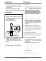
1
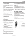
Push-To-SetTM Intermittent Suction Unit (PTS-ISU) Service Manual 400 300 500 60 70 600 80 50 40 High Flow High Vacuum 20 90 700 10 a -mm F H F H M Hg L L ANSI PTS-ISU - Analog 100 100 - kP M 200 30 MEDICAL VACUUM ISO PTS-ISU - Analog ANSI/ISO PTS-ISU - Analog 8700-0001-000, Rev4 (11/2010) User Responsibility IMPORTANT: Federal law in the U.S.A. and Canada restricts this device for sale by or on the order of a license medical practitioner. WARNING: This device is to be used only by persons who have been adequately instructed in its use. WARNING: Do not use this device in the presence of flammable anesthetics. Static charges may not dissipate and a possible explosion hazard exists in the presence of these agents. This Product will perform in conformity with the description thereof contained in this operating manual and accompanying labels and/or inserts, when assembled, operated, maintained and repaired in accordance with the instructions provided. This Product must be checked periodically. A defective product should not be used. Parts that are broken, missing, plainly worn, distorted or contaminated should be replaced immediately. Should such repair or replacement become necessary, see the Ohio Medical service manual for service or repairs to this product. For service advice, Ohio Medical recommends that a telephone request be made to the nearest Ohio Medical Regional Service Center. This product or any of its parts should not be repaired other than in accordance with written instructions provided by Ohio Medical or by Ohio Medical trained personnel. The Product must not be altered without the prior written approval of Ohio Medical’s Quality Assurance Department. The user of this Product shall have the sole responsibility for any malfunction which results from improper use, faulty maintenance, improper repair, damage, or alteration by anyone Product Date Coding: AAA A 12345 This alpha character indicates the year of product manufacture and when the serial number was assigned; “L” = 2007, “M” = 2008, “N” = 2009, etc. “I” and “O” are not used. Technical Competence other than Ohio Medical. Genuine replacement parts manufactured or sold by Ohio Medical must be used for all repairs. The procedures described in this service manual should be performed by trained and authorized personnel only. Maintenance should only be undertaken by competent individuals who have a general knowledge of and experience with devices of this nature. No repairs should ever be undertaken or attempted by anyone not having such qualifications. Read completely through each step in every procedure before starting the procedure; any exceptions may result in a failure to properly and safely complete the attempted procedure. 8700-0001-000 Rev4 Table of Contents 1.1 Definitions ............................................................1 1.2 Abbreviations .......................................................1 7.5 Digital Gauge .....................................................13 7.5.1 Removal of Batteries ................................13 7.5.2 Inserting Batteries 2/ Scope 8/ Service Checkout Procedure 2.1 ANSI Vacuum Regulator ......................................2 2.2 ISO Vacuum Regulator ........................................2 8.1 Setup .................................................................14 8.2 Push-To-Set™ Test............................................14 8.3 Leak Test – Supply Side ....................................14 8.4 Flow Test ...........................................................14 8.4.1 Continuous Mode Flow Test .....................14 8.4.2 Intermittent Mode Flow Test .....................14 8.5 Timing Cycle Adjustment ...................................15 8.6 Gauge Test ........................................................15 8.7 Regulation Test ..................................................16 8.8 Vacuum Buildup/Bleed-down Test – Intermittent Mode........................................................................16 8.9 Bleed Test ..........................................................16 8.10 Leak Test – Patient Side ..................................16 1/ Definitions and Abbreviations 3/ Description and Specifications 3.1 Description...........................................................2 3.2 Specifications ......................................................3 4/ Operation 4.1 Equipment Setup .................................................4 4.1.1 Attaching the OST ......................................4 4.2 Mode Selection ....................................................5 4.3 Setting the Suction Level .....................................5 4.4 Pre-Use Checkout Procedure..............................5 4.5 Patient Setup .......................................................6 5/ Cleaning and Sterilization 5.1 Cleaning ..............................................................6 5.1.1 Routine Exterior Cleaning...........................6 5.1.1.1 Approved Cleaning Solutions .........6 5.1.2 Internal Component Cleaning .....................7 5.1.2.1 Approved Flush Solutions ...............7 5.1.3 Cold Flush Procedure .................................7 5.2 Disinfection ..........................................................7 6/ Troubleshooting ............................................8 7/ Service – Disassembly and Assembly 9/ Maintenance 9.1 General Maintenance of Suction Equipment ...............................................................17 9.2 Recommended Maintenance Schedule.............17 9.2.1 Maintenance Schedule ............................17 9.3 Repair Policy .....................................................18 9.4 Technical Assistance .........................................18 9.5 Return Instructions ............................................18 9.6 Installation Procedure for Adapters/Probes and Fittings ..............................................................18 10/Ordering Information 10.1 Illustrated Parts...........................................19-20 7.1 Service Tools and Equipment ............................ 11 7.2 PTS-ISU Disassembly/Assembly ...................... 11 7.2.1 Disassembly ............................................. 11 7.2.2 Assembly ..................................................12 7.3 Regulator Module ..............................................13 7.3.1 Disassembly .............................................13 7.3.2 Assembly ..................................................13 7.4 Timing and Flow Control Valves ........................13 7.4.1 Disassembly .............................................13 7.4.2 Assembly ..................................................13 8700-0001-000 Rev4 TOC 1/Definitions and Abbreviations 1.1 Definitions Note: A note provides additional information to clarify a point in the text. Important: An important statement is similar to a note but of greater emphasis. CAUTION: A CAUTION statement is used when the possibility of damage to the equipment exists. WARNING: A WARNING statement is used when the possibility of injury to the patient or the operator exists. 1.2 Definitions in Hg in ISU kPa LPM mm Hg mm oz | (CONT) |O|O (INT) O (Off) °C °F N-m ft-lb in-lb DISS OES NCG BOC NPT MPTS I.D. gal. PTS PTFE NG RH 1 Inches of mercury Inch Intermittent Suction Unit Kilo pascals (kPa x 7.50 = mm Hg) Liters per minute Millimeters of mercury (mm Hg x .133 = kPa) Millimeters Ounces Continuous (On) Intermittent (On/Off) Off Degrees Celsius Degrees Fahrenheit Newton-Meter (N-m x .737 = ft-lb) Foot-Pound Force (ft-lb x 1.356 = N-m) Inch-Pound Force (ft-lb x 12 = in-lb) Diameter Index Safety System Oxequip Suction® National Compressed Gases (Chemetron) British Oxygen Corporation National Pipe Thread (USA) Multi-Purpose Therapy Stand Inner Diameter gallon Push-To-SetTM Teflon® Naso - Gastric Relative Humidity 8700-0001-000 Rev4 2/Scope 3/Description/Specifications This service manual contains service, maintenance and parts information for the Push-To-SetTM Intermittent Suction Unit (PTS-ISU) 2.1 Note: Part numbers given are for Vacuum Regulators without fittings or adapters/probes. F H F H M M L L The PTS-ISU is a dual purpose vacuum regulator which provides either intermittent or continuous suction. It can be used for NG drainage (intermittent) or pharyngeal/tracheal (continuous) suctioning throughout the hospital. A patented safety feature Push-To-Set™ (PTS) automatically occludes the patient circuit as the desired vacuum level is selected. It prevents higher than desired vacuum levels from being accidentally delivered when patient suctioning begins. The suction control knob must first be pushed and then turned to set vacuum levels. MEDICAL VACUUM 2.1 WARNING: Do not use this device in the presence of flammable anesthetics. Static charges may not dissipate and possible explosion hazard exists in the presence of these agents. ANSI Vacuum Regulator Analog/Digital PTS-ISU 8700-1251-900 (1271,7251, 7271) 3.1 Description Each unit contains a dual spring regulator module to regulate and adjust suction which is precise in the critical care range (0-200 mmHg/26.7 kPa) and quickly moves to full wall vacuum for resuscitation. It requires only two turns from zero to full wall vacuum. Each unit contains a vacuum gauge, an ON/OFF switching module and adjustable timing valves. PTS-ISU Digital 8700-1351-900 (1371, 1372, 7351, 7371, 7372) ISO Vacuum Regulator Analog/Digital Note: Part numbers given are for Vacuum Regulators without fittings or adapters/probes. In use, the vacuum source is connected through the regulator module which functions as an automatic valve. Rotating the suction control knob adjusts the position of the regulator module and selects a predetermined level of suction. Vacuum Gauge Mode Selector Switch Adapter/Probe Port 400 300 500 60 70 600 80 50 40 High Flow High Vacuum 700 200 30 20 90 10 100 F H F H M M L L Suction Control Knob 100 - kP MEDICAL VACUUM a Hg -mm PTS-ISU 8700-1253-900 (1273) PTS-ISU Digital 8700-6353-900 (6373, 6372) Fitting Port Figures 1 Figure 2: Front and Side View 8700-0001-000 Rev4 2 3/Descriptions/Specifications (3.1 Description Continued) During use, as the flow requirement increases, the valve automatically opens to maintain suction at the preset level. Conversely, when the flow requirement decreases, the valve automatically closes to maintain suction at the preset level. The same mechanism compensates for changes in supply vacuum to automatically maintain the pre-set suction level. 3.2 Specifications Gauge: Accuracy (Analog): ±5% of full scale deflection Accuracy (Digital): ±1% of full range @ 22oC Flow Rates | Continuous (CONT) Mode - 0 - 80 LPM without fittings at full increase setting depending on supply vacuum and open air flow |O|O Intermittent (INT) Mode - 8 LPM with the suction control knob set to 120 mm Hg/16 kPa Regulated Suction Range: vacuum 0 to 200 mm Hg/0 to 26 kPa and up to full wall Pre-Set Timing Cycles: On time cycle-15 seconds ± 3 seconds Off time cycle-8 seconds ± 3 seconds Weight: (Less Fittings) 20 oz/567 grams Dimensions: (Less Fittings) Height: 6.5 inches/16.5 cm Width: 2.8 inches/7.1 cm Depth: 4.8 inches/12.2 cm Environmental Specifications Operating Temperature Range: Storage Temperature Range: Operating and Storage Relative Humidity: 3 50oF (10oC) to 104oF (40oC) -13oF (-25oC) to 158oF (70oC) 5 to 95% RH (Non-condensing) 8700-0001-000 Rev4 4/Operation Locking Gland Fitting 4.1 Equipment Setup Insert the adapter/probe into the vacuum wall outlet. If the regulator is mounted elsewhere, connect a vacuum supply hose between the regulator’s adapter/ probe and the wall outlet. WARNING: Connection to pressure sources, even momentarily, could injure the patient or operator and damage the equipment. Use hospital-supplied suction tubing between the vacuum regulator and the collection container, and between the patient port of the collection container and the patient (minimum inside diameter is 6 mm[0.25 in]). An Ohio Medical Hydrophobic Filter or Hydrophilic Filter and Overflow Safety Trap (OST) should be used between the collection container and regulator to prevent contamination of the regulator, wall outlet and pipeline system. Figure 3 1. Raise the sleeve and insert the OST into the regulator fitting. 2. Turn the trap clockwise about one and a half turns to engage the threads. The trap does not need to be screwed tight; an O-ring in the regulator fitting provides a vacuum seal. The trap should rotate freely to allow the desired nipple positioning. 3. Lower sleeve to lock trap in position. 1 Regulator 2 Sleeve 3 1 2 OST 3 ISO 10079-3 (BS 7259: Part 2, section 5.1.2) states that “the usable volume of the collection container shall not be less than 500 ml.” Suction Filters DISS fitting Hydrophilic: 20 Pack 200 Pack Figure 4 Nipple 6730-0350-800 6730-0351-8000 Hydrophobic: 3 Pack 10 Pack 50 Pack Nipple 6700-0570-800 6700-0571-800 6700-0572-800 Threaded 6700-0580-800 6700-0581-800 6700-0582-800 Note: For proper installation of adapters/probe and fittings, see section 9. 4.1.1 Attaching the Overflow Safety Trap (OST)) 1. Insert the OST into the regulator fitting. Situate the nipple in the desired position. 2. Turn the DISS wing nut clockwise to engage threads and tighten (there is no O-ring, so the vacuum seal depends on a tight connection). 1 1Regulator 2Wing nut 2 3OST CAUTION: To help prevent aspirate from entering the regulator as a result of misuse, an OST should be attached prior to its use. Aspirate in the regulator may impair its operation. The use of the OST and suction filter will help prevent this and extend the life of suction equipment. 8700-0001-000 Rev4 3 4 4/Operation Figure 7 4.2 Mode Selection 2. Push and rotate the suction control knob until the vacuum gauge indicates the required setting. Figure 5 IOIO (INT)- suction is intermittent (cycled “on” and “off”) and the suction level can be adjusted with the suction control knob when cycled “ON”. CAUTION: The suction control knob must be O (OFF)- No suction is supplied to the patient. completely depressed in order to adjust the vacuum level. Failure to do so may damage the vacuum regulator. 4.4 Pre-Use Checkout Procedure WARNING: The Pre-Use Checkout Procedure I (CONT) - Suction is continuous and can be adjusted with the suction control knob. must be performed before using the equipment on each patient. If the regulator fails any part of the Pre-Use Checkout Procedure, it must be removed from service and repaired by qualified service personnel. All tests must be performed with supply vacuum of 500 mmHg (67 kPa) minimum. 1. Turn the mode selector switch to O (OFF). Push and rotate the suction control knob one full turn clockwise (increase). Release. The gauge needle should not move. 2. Move the mode selector switch to I (CONT). The gauge should indicate vacuum. Push and rotate the suction control knob fully counter-clockwise (decrease) until it stops and release. The gauge needle should move to zero and remain there. 4.3 Setting the Suction Level Figure 6 1. Turn the mode selector switch to I (CONT). 3. Push the suction control knob and set the following: REGULATOR (Type) PTS-ISU SETTING Increase the suction to 90 mmHg (12 kPa) 4. Slowly release and push the suction control knob to create various flow rates through the regulator. Check that the suction level is maintained when the knob is fully pushed in. 5 8700-0001-000 Rev4 4/Operation 5/Cleaning 5. Move the mode selector knob to IOIO. Check that the intermittent timing cycles are approximately 15 seconds on and 8 seconds off by observing the gauge needle. Note: The PTS-ISU starts in the ON cycle. 5.1 Cleaning 6. Push the suction control knob and reduce the suction to zero. Set the mode selector to O (OFF). WARNING: After patient use, regulators may be contaminated. Handle in accordance with your hospital’s infection control policy. WARNING: Perform a service checkout procedure following cold flushing. Validate the selected cleaning/disinfection procedure. Failure to do so may result in patient use of a product which is assumed to be clean/ disinfected and is not. 4.5 Patient Setup Figure 8 1. Make sure the Pre-Use Checkout Procedure has been performed. CAUTION: Unit failure due to cold flushing is not the responsibility of Ohio Medical and may invalidate the warranty. Failure to adequately dry the product following a cold flush may damage the working parts which are designed for pneumatic air-flow only. Failure to disassemble to check O-ring and filter status may render the unit inoperative. 2. Move the mode selector switch to I (CONT) and push suction control knob. 3. Set the prescribed suction level. CAUTION: Suctioned fluids drawn into a vacuum regulator do not stop in the regulator. They proceed through it into the wall outlet and pipeline system. Failure to clean and disinfect the wall outlet and pipeline system may result in damage to this equipment. 5.1.1 Routine Exterior Cleaning Routine cleaning of the regulator is recommended as a standard procedure after each use. Wipe all exterior surfaces with a solution of water and mild detergent. 5.1.1.1 Approved Cleaning Solutions CAUTION: The suction control knob must be completely pushed in to adjust the vacuum level. Failure to do so may damage the vacuum regulator. 4. Move the mode selector switch to O (OFF). • Virex® (Quaternary Ammonium 0.2%): Mixture of 1 fl. oz. of Virex® to 1 gallon (128 fl. oz.) tap water using Virex®128 • Kleenaseptic® Full strength from spray can • Bleach (Sodium Hypochlorite 0.5%): Mixture of 13 fl. oz. of Clorox household bleach to 1 gallon (128 fl. oz.) tap water • Betco® TB Plus Mixture of 1 fl. oz. to 1 gallon (128 fl. oz.) tap water • Glutaraldehyde • Isopropyl Alcohol 70% • Hydrogen Peroxide 3% • Cavicide®: Ready to use full strength 5. Attach tubing from the vacuum regulator to the vacuum port of the collection container. 8700-0001-000 Rev4 6 5/Cleaning 5.1.2 Internal Component Cleaning 5.2 Disinfection CAUTION: Cleaning the gauge may result in Should misuse occur resulting in accidental flooding of the regulator, the regulator may be disinfected using Ethylene Oxide (ETO). After disinfection, follow the service checkout procedures in Section 8. damage. 1. Refer to the Service - Disassembly and Assembly instructions. (Section 7) 2. All internal components with the exception of the gauge may be cleaned with a solution of warm water and mild detergent. 3. Dry all components with a lint free cloth before assembly. Dry internal passages using vacuum flow or compressed air. WARNING: Following disinfection with ethylene oxide, parts should be quarantined in a well ventilated area to allow dissipation of residual ethylene oxide gas absorbed by the material. Follow ETO processor’s recommendation for specific aeration periods required. 4. Perform Service Checkout Procedure (Section 8). CAUTION: Do not steam autoclave or liquid sterilize the PTS-ISU. Severe impairment to the operation of the regulator will result. 5.1.2.1 Approved Flush Solutions Warm water and mild detergent CAUTION: Disinfection with ethylene oxide mixtures may cause crazing (minute superficial cracking) of some plastic parts. 5.1.3 Cold Flush Procedure If desired, the vacuum regulator can be cold-flushed as part of a cleaning or disinfecting procedure. Set up a collection canister or liner between the vacuum source and the adapter/probe port of the vacuum regulator to receive the flush solution. Suction through the vacuum regulator an adequate amount of cold disinfectant to satisfy the infection control requirements of the hospital. Use only approved cleaning/flushing solutions. Make sure those made from concentrates are newly mixed to ensure effectiveness. Flush both the continuous and intermittent vacuum circuits thoroughly. Adequately aerate both the continuous and intermittent circuits with vacuum flow or compressed air until all internal channels, switches, gauge ports and regulating mechanisms are dry. Disassemble to check O-rings for adequate lubricant and filters for proper function following any cold flush procedure. Perform Service Checkout Procedure (Section 8). 7 Note: The PTS-ISU should only be disinfected if it is contaminated or maintenance is to be performed. 1. The regulator should be disinfected with the mode selector switch in the |O|O (INT) position. 2. Ethylene oxide mixtures can be used at temperatures of 125 to 135°F (52-57°C ). If this temperature cannot be obtained, room temperature sterilization with 100% ethylene oxide can also be used. Disinfection is NOT recommended as a frequent procedure. 3. After each disinfection check the condition of the internal filters. Replace any shrunken filters before returning the regulator to service. 4. Perform Service Checkout Procedure (Section 8). 8700-0001-000 Rev4 6/Troubleshooting Place the regulator in the vertical position and connect to a supply vacuum of 500 mmHg (66.7 kPa). Problem A. B. No gauge indication and no suction in any setting Regulator module malfunction C. No gauge indication but suction is being delivered D. Gauge indication but no suction is being delivered Possible Causes Remedy 1. No supply vacuum 1. Correct supply problems 2. Kinked tube 2. Straighten tube 3. Poor connection 3. Check all connections and seals 4. Blocked wall outlet 4. Unblock outlet 5. Blocked adapter/probe port 5. Unblock port 6. Blocked backplate 6. Clean with soap and water and a pipe cleaner 7. Regulator module malfunction 7. See “regulator module malfunction” under the Problem column in this section of the manual 8. In the OFF cycle of the IOIO mode 8. In the IOIO mode the regulator starts in the ON cycle. However, if the unit was stopped in the OFF mode, and immediately re-started, it may take about 5 seconds to enter ON mode. 9. Depleated batteries 9. Charge batteries 1. O-ring, quad ring, or diaphragm failure 1. Replace rubber components 2. Cap not completely snapped to housing 2. Fully snap cap onto housing 3. Springs are not installed correctly 3. Ensure that springs are properly installed. 4. Pinched diaphragm 4. Reinstall or replace diaphragm 1. Blocked gauge pressure sensing orifice 1. Unblock orifice 2. Blocked gauge pathway (through Unilogic Module) 2. Clear pathway 3. Failed gauge o-ring seal 3. Reinstall or replace the o-ring 4. Gauge mechanism/ electronics is damaged 4. Replace gauge 1. Knob fails to return when pushed 1. Remedy i. ii. iii. iv. v. Jiggle knob Verify actuator is installed properly Replace worn drive gear Replace cover if worn splines in well Replace Push-To-Set™ assembly 2. Blocked fitting port 2. Unblock port 3. Overflow Protection Device Shut-off 3. Reset float, empty the autoclave Overflow Protection Device 4. Blocked external filter 4. Replace external filter 5. Blocked fitting 5. Replace fitting 6. Leak in system 6. Remedy: i. ii. 8700-0001-000 Rev4 Check lid is secure on the collection container Check tubing connections 8 6/Troubleshooting Problem E. Suction level cannot be adjusted F. Suction level can be adjusted without pushing the knob in G. Insufficient flow through regulator H. Inaccurate gauge reading Possible Causes Remedy 1. Failure to push knob and rotate 1. Push and rotate to set vacuum level 2. Regulator module is stuck in full OFF or full ON position 2. Rotate knob to un-stick 3. Regulator module malfunction 3. See “Regulator module malfunction” under the Problem column in this section of the manual 1. Worn or broken drive gear 1. Replace drive gear 2. Worn or broken splines in well 2. Replace cover 3. Broken knob 3. Replace knob 1. Partial blockage in wall supply 1. Confirm wall supply is open and air flow meets minimum hospital requirements 2. Partial blockage in regulator 2. Perform the Flow Test in the Service Checkout Procedure section of this manual 3. Push-to-Set™ spring assembly does not return, blocking the flow path 3. Remedy: 4. Knob fails to return when pushed 4. 5. Vacuum relief plug leaks or is 5. missing Replace or install correctly 6. Positive pressure relief valve leaks or is missing 6. Replace or install correctly 1. Damaged gauge 1. Replace gauge 1. Blocked bleed filter and/or orifice 1. Clear orifice and replace filter 2. Damaged gauge 2. Replace gauge 3. Cross threaded regulator module 3. Install correctly 4. Regulator module malfunction 4. See “Regulator module malfunction” under the Problem column in this section of the manual 1. Selector switch not fully in CONT or INT position 1. Move fully to desired position 2. Failed selector switch seal 2. Remedy: i. ii. Jiggle knob Replace Push-To-Set™ assembly See remedy D1 in this section of the manual Note: The gauge needle (analog gauge) should return to the stop pin when no suction is being supplied. I. With the knob pushed in, unable to decrease the suction level and gauge does not return to zero when switched to O (OFF) J. Limited suction in any setting and whistling noise from inside the regulator 9 a. b. 8700-0001-000 Rev4 Ensure Unilogic Module screws are adequately tightened Replace selector switch 6/Troubleshooting Problem Possible Causes Remedy Whistling/buzzing noise from inside the regulator 1. Cap-foam plug missing or deteriorated/shrunk 1. Replace 2. Cap-foam plug pushed too far into cap 2. Replace or install just flush with underside of cap Suction is delivered in the CONT mode but the INT mode will not cycle 1. Flow control valve is blocked or turned fully in 1. Turn valve counter-clockwise until unit cycles and/or inspect valve seat area 2. Timing valves turned fully in and/or clogged 2. Turn valve counterclockwise until unit cycles and/or inspect valve seat area 3. Unilogic Module malfunction 3. Replace filters and/or module 4. Failed selector switch seal 4. See remedy J2 in this section of the manual 5. Blocked manifold 5. Inspect manifold flow paths 6. Missing, damaged or incorrectly installed o-rings 6. Replace or install o-rings 7. Degraded or clogged Unilogic Module filters 7. Remedy: 1. Clogged beige filter on the Unilogic Module 1. Replace filter 2. Gauge mount foam misaligned 2. Align N. Gauge not aligned 1. Gauge mount foam missing, torn or misaligned 1. Replace or align O. Longer than expected gauge bleed down time 1. Blocked or clogged gauge bleed 1. 2. Unblock or unclog gauge bleed Replace filter K. L. Note: The regulator will always start in the ON mode. Be sure that you wait at least 20 seconds with the regulator port occluded to determine if regulator is functioning. M. Longer than expected O (OFF) cycle time i. ii. 8700-0001-000 Rev4 Replace filters Replace Unilogic Module 10 7/Service - Disassembly and Assembly CAUTION: The Gauge Assembly must be 7.1 Service Tools and Equipment handled with utmost care. Do not rest the gauge on its face. CAUTION: Use of lubricants other than recommended, may degrade plastic or rubber components. Note: See SECTION 10.1 Illustrated Parts The following items should be on hand during any service procedure: 1. Remove the four case screws from the back of the unit. • Supply Vacuum: 500 mmHg/67 kPa minimum and 50 LPM open air flow minimum 2. Holding the unit face up, carefully pull the case and Knob Assembly off the backplate. Remove, clean, and/or replace the Cover Strip. • Phillips head screwdriver, No. 2 • Flat head screwdriver, 1/4 inch • Phillips head screwdriver, No. 1 • Open end adjustable wrench • Pipe Cleaner • Wooden toothpick (O-ring remover) • Tweezers (Filter remover) • Tubing clamp • 1500 ML suction canister with lid • Bubble leak tester • Stop watch or VACUTIMER (Ohio Medical P/N 6700-0438-800) • 3. To remove the Gauge Assembly and foam, grasp and pull straight out. Lubricate or change the gauge o-rings if needed. 4. Remove Actuator and Push-To-SetTM Assembly. 5. To remove the Regulator Module, grasp the stud and rotate clockwise. Note: To disassemble the Regulator Module, refer to the Regulator Module Assembly section. Vacuum Calibration Gauge, zero to full wall vacuum range (0-760 mmHg/0-101.3 kPa), recommend Dwyer Series DPG-100 Digital Pressure Gauge or equivalent (Dwyer Instruments, Inc., 219-879-8000) • 50 L/min Flowmeter, 6-50 L/min scale, recommend Dwyer VFA-26 or equivalent (Dwyer Instruments) • 10 L/min Flowmeter, 1-10 L/min scale, recommend Dwyer VFB-66 or equivalent (Dwyer Instruments) 6. Remove the Unilogic Module by removing the 2 deep center side screws (No. 1 Phillips). Remove and check beige filter, green filter and seven o-rings. Replace filters if needed. Replace or lubricate o-rings if needed. 7. If needed, remove the Timing Valve and the Flow Control Valve with a flathead screwdriver. Replace or lubricate the o-rings if needed. 8. Remove the Detent Plate and the Mode Selector Switch. Replace filter if excessive wear or damaged. 9. Remove the Gauge Bleed Hole Filter from the Manifold Assembly. Replace if needed. 10. Grasp the Positive Pressure Relief Valve, and pull from the Manifold Assembly. Replace if torn or damaged. 11. If needed, remove the Faceplate as follows: a. Carefully peel back and remove label from the knob. 7.2 PTS-ISU 7.2.1 Disassembly/Assembly b. Disconnect the knob from the Drive Gear by grasping the knob to remove the knob screw. WARNING: If the vacuum regulator is repaired c. Rotate the Faceplate Collar counterclockwise to remove. or disassembled in any manner, the service checkout procedure must be performed before using the equipment on the patient. WARNING: To ensure service personnel are d. Remove the Faceplate. 12. Grab pull-tab on Vacuum Relief Plug and remove. Replace if deteriorated. not exposed to hazardous contamination, clean and disinfect all suction equipment before disassembly. 11 8700-0001-000 Rev4 7/Service - Disassembly and Assembly b. Also insert one o-ring into the gauge orifice. Ensure o-ring is flush 7.2.2 Assembly CAUTION: To prevent stripping the plastic case threads, place the manifold screw in the hole and turn counterclockwise until it drops into the original threads. Tighten screw. 1. Before assembly, lubricate all o-rings and the rubber surface on the inside of the Mode Selector Switch with a small amount of 1Dow® 111. 2. Place the Gauge Bleed Hole Filter in its proper location. 3. Install the Positive Pressure Relief Valve and the Vacuum Relief Plug. 1 Dow Corning® 111 Valve Lubricant & Sealant, or equivalent 4. Unilogic Module Assembly a. Install beige and green filters in the Unilogic Module. b. Install the seven o-rings on the posts of the Unilogic Module. c. If removed during disassembly, install Timing Valves and/or Flow Control Valve. Rotate each clockwise about 3 turns from thread engagement. 5. Mode Selector Switch Assembly a. Place the Mode Selector Switch into the Manifold Assembly, rubberized side down. b. Install the Detent Plate on the Manifold Assembly, detent fingers facing down. c. Install the Unilogic Module. Push down until all posts and o-rings are seated into Manifold Assembly. Firmly tighten the two small screws (4 in/lbs or 0.45 N-m). The Unilogic Module secures the Mode Selector Switch and seals it against leaks. d. After tightening the screws, test Mode Selector Switch movement, which should be firm. Do not over tighten. 6. Install the Regulator Module Assembly by turning counterclockwise (left handed threads). Rotate the stud so the flats are vertical. c. Attach the foam to the back of the gauge with the short leg at six o’clock. Connect the Gauge Assembly to the gauge post on the Unilogic Module Assembly. Ensure the Gauge Assembly is properly aligned. 10. Installing Case a. With Faceplate and Knob Installed: i. With the flats on the outside of the drive gear horizontal, pull the Knob to lock in position. ii. Holding manifold assembly face up, place and align the Case and Knob Assembly onto the Manifold Assembly with the Mode Selector Switch in the O (OFF) position. iii. Carefully center the slot in the Cover Strip to fit around the Mode Selector Switch tab. iv. Install the four case screws. b. Without Faceplate and Knob Installed: i. Install Drive Gear on Regulator Module Assembly stem. ii. Holding Manifold Assembly face up, place and align the Case onto the Manifold Assembly with the Mode Selector Switch in the O (OFF) position. iii. Carefully center the slot in the Cover Strip to fit around the Mode Selector Switch tab. iv. Install the four case screws. v. Install the Faceplate with the top tab in the case notch. vi. Install Faceplate Collar, flat surface down and finger-tighten clockwise. vii. Place the Knob on the Drive Gear protruding through Case and insert screw. Hold the knob to tighten the screw. viii. Replace the Knob label. 11. Install adapters/probes and fittings. 7. Install Push-To-SetTM Assembly. 8. Position Actuator on Unilogic Module over Regulator Module Assembly and resting on PushTo-SetTM Assembly. Note: For proper installation of Adapters/Probes and Fittings, see section 9. 9. Gauge assembly a. Attach small o-ring to the gauge post on the Unilogic Module Assembly. 8700-0001-000 Rev4 12 7/Service - Disassembly and Assembly 7.4 Timing and Flow Control Valves 7.3 Regulator Module Note: See SECTION 10.1 Illustrated Parts CAUTION: Do not over-tighten the Timing Valve CAUTION: Do not lubricate any internal components of the Regulator Module Assembly. 7.3.1 or Flow Control Valve stems. Needle portion of valves may be damaged. 7.4.1 Disassembly Disassembly 1. Remove small quad-ring from piston with stem and o-ring from Housing. Lubricate or replace if needed. 1. Remove Timing Valve and Flow Control Valve by turning counterclockwise with a flat-head screwdriver. 2. Lift and pull tabs to pry off and remove Cap. 2. Replace and/or lubricate o-rings as needed. 3. Peel Diaphragm from Piston with Stem Assembly. 4. With piston facing down, lift threaded Housing to separate. 7.4.2 Assembly 1. Carefully insert and tighten the Timing Valves. 5. Remove springs from stem. 2. Press Flow Control Valve in to engage threads then tighten. 7.3.2 3. Rotate each clockwise about 3 turns from thread engagement. Assembly 1. Place folded Diaphragm on Piston with stem. Make sure small number on Diaphragm is showing. 2. With stem up, install springs. 3. Place threaded Housing on Piston with Stem Assembly. 7.5 Digital gauge Please Note: Both batteries are positioned with the positive side facing up relative to the display. 4. Install quad ring on Piston with Stem. 7.5.1 Removal of Batteries 5. Snap cap into place. Ensure small tabs are fully seated against the Cap. 1. Remove digital gauge as described in 7.2.2. 6. Install o-ring on threaded Housing. 2. Using a small flat head screwdriver, push batteries out at a 45o angle. 7.5.2 Inserting Batteries 1. Place negative side of battery into battery slot first (battery will be at an angle). 2. Then using a flat head screwdriver, gently push in positive battery contact while sliding battery in place. 13 8700-0001-000 Rev4 8/Set-Up 8.1 Set-up 1. Verify there is 500 mmHg ± 10 mmHg (67 kPa ± 1.3 kPa) vacuum on the supply gauge. 2. The supply open flow must be 50 LPM minimum. Important: Prior to venting port “A” of the Bubble Leak Tester to atmosphere (i.e. turning the supply regulator off), ensure the tubing from port “B” has been disconnected from the adapter/probe port of the vacuum regulator. 3. Connect the supply vacuum to the adapter/probe port. 888 Test Gauge Adaptor/ Probe Port Patient/Fitting Port Vacutimer Test Gauge OFF/ON VACUUM PHASE 888 0-10 LPM Flowmeter Occlusion 0-50 LPM Flowmeter 1500cc Canister Figure 9: Service Checkout Procedure Setup Figure 10: Bubble Leak Test - Supply Side 8.4 Flow Test 8.2 Push-To-Set™ Test Remove the Bubble Leak Tester from the supply vacuum connection and connect the supply vacuum directly to the regulator adapter/probe port. 1. Connect the 10 LPM Flowmeter to the patient port. 8.4.1 Continuous Mode Flow Test 2. Set 200 mmHg/26.6 kpa on the gauge and keep the knob pushed in. 1. Connect the regulator fitting port to the 50 LPM flowmeter. 3. Make certain leakage at the patient port connection is no more than 1 LPM. 2. Turn the mode selector switch to I (CONT). 4. While observing the flowmeter, push and rotate the knob. Leakage should be no more than 1 LPM. Release the knob. It should fully return. 3. Push and rotate the suction control knob fully clockwise (increase). 4. Verify the flow rate exceeds 40 LPM. 8.4.2 8.3 Leak Test - Supply Side 1. Connect the supply vacuum tubing to port “A” of the Bubble Leak Tester. 2. Connect port “B” of the Bubble Leak Tester to the regulator adapter/probe port. 3. Turn the mode selector switch to O (Off). Allow the fitting port to be open to air. 4. Wait 10 seconds. No More than 6 bubbles should appear in the next 10 seconds. Intermittent Mode Flow Test 1. Remove the face plate as follows: a. Carefully peel back and remove label from the knob b. Disconnect the knob from the drive gear by grasping the knob to remove the knob screw. c. Rotate the faceplate collar counterclockwise to remove. d. Remove the face plate. 8700-0001-000 Rev4 14 8/Set-Up 2. Use a flathead screwdriver to rotate the flow control valve two turns counterclockwise from its seat. 3. Set 120 mmHg/16 kpa on the regulator gauge. 4. Connect the regulator fitting port to the 10 LPM flowmeter. 5. Turn the mode selector switch to IOIO (INT). 6. During the “ON” cycle, adjust the intermittent flow rate to 8 LPM +/- 1 LPM. To increase the flow rate turn the valve counterclockwise. To decrease the flow rate turn the valve clockwise. Note: If the regulator does not cycle “OFF” after 20 seconds, use a flathead screwdriver and rotate the “ON” timing valve stem counterclockwise until the regulator cycles “OFF.” increase the time, turn the timing valve stem clockwise. To decrease the time, turn the timing valve stem counterclockwise. Use Ohio Medical VACUTIMER (P/N 6700-0438-800) to digitally measure timing cycles. 10. Install the faceplate as follows: a. Install the faceplate with the top tab in the case notch. b. Install faceplate collar, flat surface down and finger-tighten clockwise. c. Place the knob on the drive gear protruding through and insert screw. Hold the knob to tighten the screw. d. Replace the knob label. 8.5 Timing Cycle Adjustment WARNING: If the screws on the timing valves “ON” Valve are turned all the way clockwise, the PTS-ISU will not cycle. “OFF” Valve Factory Settings: “ON” Cycle: 15 seconds +/- 3 seconds “OFF” Cycle: 8 seconds +/- 3 seconds To set the timing cycles, perform the following procedure. Brass Flow Control Valve 1. Occlude the fitting port or connect Vacutimer to fitting port. 2. Turn the selector switch to | (CONT). 3. Set 120 mm Hg/16 kPa on the regulator gauge. 4. Turn the mode selector switch to |O|O (INT) with the fitting port still occluded. 5. Wait 20 seconds. 6. If the regulator does not cycle “OFF” use a flathead screwdriver to rotate the “ON” timing valve stem counterclockwise until the regulator cycles “OFF”. Figure 11: Setting Timing Cycles and Intermittent Flow Rate 8.6 Gauge Test Note: All Ohio Medical Analog Gauges are supplied with an accuracy of +/- 5% of full scale deflection throughout their range. The PTS-ISU vacuum gauges have an accuracy of +/- 10 mmHg/1.3 kPa. 7. Wait 20 seconds. Note: Digital gauges are supplied with an accuracy of +/- 1% of full range @ 22oC 8. If the regulator does not cycle “ON”, use a flathead screwdriver to rotate the “OFF” timing valve stem counterclockwise until the regulator cycles “ON”. Note: All gauge needles should return to the stop pin when no suction is being supplied. Gauges which do not comply may be out of calibration. 9. Once the regulator has completed an “ON” and “OFF” cycle, fine tune each cycle to the desired time by adjusting the corresponding valve. To 15 Note: When checking gauge accuracy, be sure that the calibration gauge has an accuracy of +/-1% full scale deflection or better. 8700-0001-000 Rev4 8/Set-Up 1. Connect the regulator fitting port to the vacuum calibration gauge with tubing. 2. Turn the mode selector switch to I (CONT). 3. Assure the regulator gauge is in agreement with the vacuum calibration gauge within the +/- 10 mmHg/1.3 kPa tolerance. Recommended test points are: PTS-ISU: 40, 80, 140, and 200 mmHg (5, 10, 18, and 26 kPa) 4. Push and rotate the suction control knob fully clockwise (increase) and verify the gauge reading is in the FULL VAC range (vacuum calibration gauge should read 450 mmHg/59.8 kpa or higher). 5. Turn the mode selector switch to IOIO (INT). stop pin) in 5 seconds. 6. If the regulator fails either the build-up or bleeddown test, replace the regulator module. 8.9 Bleed Test 1. Turn the mode selector switch to I (CONT). 2. Push and rotate the knob to set 120 mmHg/16 kPa. 3. Turn the mode selector switch to O (OFF) and observe the gauge needle. It must return to zero within 10 seconds. 8.10 Leak Test – Patient Side 6. Verify the gauge reading is in the FULL VAC range (vacuum calibration gauge should read 400 mmHg/50 kPa or higher). 1. Turn the mode selector switch to O (OFF). 7. Turn the mode selector switch to I (CONT). 3. Keep port “B” open to air. 8. Push and rotate the suction control knob fully counterclockwise (decrease) and verify the gauge reading decreases to zero. 4. Push and rotate the suction control knob fully counterclockwise (decrease). 2. Connect the regulator fitting port tubing to port “A” of the bubble leak tester. 5. Turn the mode selector switch to I (CONT). 6. Wait 5 seconds. 8.7 Regulation Test 1. Disconnect the vacuum calibration gauge from the regulator fitting port. 7. No bubbles should appear in the bubble leak tester for the next 10 seconds. 2. Push and rotate the knob to set 90 mmHg/12 kPa. 3. Without rotating, release and push the knob several times. 4. Check that the regulator gauge reads between: PTS-ISU: 80 mmHg/10.7 kPa and 100 mmHg/13.3 kPa when the knob is pushed. 8.8 Vacuum Buildup/Bleed-down Test – Intermittent Mode 1. Turn the mode selector switch to IOIO (INT). 2. Connect the regulator fitting port to the 1500 ml suction canister with lid. Fitting/ Patient Port Figure 12: Bubble Leak Test - patient Side 3. Push and rotate the knob to set 120 mmHg/16 kPa. 4. During the “ON” cycle, check that the suction increases to the preset 120 mmHg/16 kPa on the regulator gauge in 5 seconds or less. 5. During the “OFF” cycle, check that the suction decreases to zero on the regulator gauge (zero 8700-0001-000 Rev4 16 9/General Maintenance of Suction Equipment 9.1 General Maintenance of Suction Equipment 2. Wipe all exterior surfaces with a solution of water and mild detergent or approved cleaning solutions. WARNING: The Pre-Use Checkout Procedure 3. Perform a careful visual inspection. must be performed before using this equipment on each patient. If the regulator fails any part of the Pre-Use Checkout Procedure, it must be removed from service and repaired by qualified service personnel. 4. Check that the high flow disposable suction filter is clean and in good condition. 5. Check that all tubing is in good condition and connected securely to the correct ports. 6. Check the floats in the Overflow Protection Device and collection canister for correct operation. WARNING: Clean and disinfect all suction equipment if contaminated before disassembly to ensure service personnel are not exposed to hazardous contamination. PTS-ISU should be kept in use or used on a rotating basis. Internal parts of unused equipment may tend to deteriorate. Maintenance of the vacuum piping system is as important as maintenance of the suction equipment. The use of collection canisters with reliable shutoff valves, Overflow Safety Trap assemblies and disposable suction filters will protect the regulator, wall outlet, and piping system. The flow rate at the wall outlet should be checked on a yearly basis and suitable cleaning of the outlets should be performed as needed. The flow rate measurement should meet NFPA99 and/or ISO standards. Routine maintenance and inspection are important to the performance of suction equipment. The following is a recommended list for care of suction equipment after each patient use. 7. Perform the Pre-Use Checkout Procedure. 9.2 Recommended Maintenance Schedule Ohio Medical vacuum regulators function for decades. They are proven to provide trouble-free service with minimum care. We recommend the following to determine the maintenance schedule appropriate for each facility: 1. Periodically (as required, but no less than annually) inspect the overall condition of the vacuum regulator. Test gauge accuracy (section 8.6 Gauge Test) and perform the Pre-Use Checkout Procedure (section 4.4). If the regulator does not pass, refer to Troubleshooting (Section 6). 2. Determine a maintenance schedule based on data from your periodic inspections. Follow the guidelines below. 1. Keep connecting tubing, fittings and adapters/ probes clean. 9.2.1 Maintenance Schedule Item Minimum Frequency Comments Service Checkout Procedure Every 24 months or as required If the regulator does not pass, refer to Troubleshooting (Section 6). Repair as needed Elastomeric parts, O-rings, gaskets, diaphragms, internal filters As required Cleaning, lubrication and replacement interval depends on hours of usage and environmental conditions. Replace, lubricate, and repair as needed 17 8700-0001-000 Rev4 9/General Maintenance of Suction Equipment 9.3 Repair Policy WARNING: Clean and disinfect all suction equipment before shipment to ensure transportation personnel and /or service personnel are not exposed to any hazardous contamination. CAUTION: Do not steam autoclave or liquid sterilize the PTS-ISU. Severe impairment to the operation of the regulator will result. The only acceptable method of sterilization is with gas (ethylene oxide). CAUTION: Only competent individuals trained in the repair of this equipment should attempt service. Do not use malfunctioning equipment. Make all necessary repairs. Have the equipment repaired by qualified service personnel or by Ohio Medical. After repair, perform the Service Checkout Procedure to ensure that the product is functioning properly, and complies with the manufacturer’s published specifications. 9.4 Technical Assistance If technical assistance is required, contact Ohio Medical technical support at +1 857-855-0800 or toll free at 866-549-6446. 9.5 Return Instructions 9.6 Installation Procedure for Adapters/Probes and Fittings CAUTION: Do not use any 4Loctite® products to seal the threads (or product which contain Methacrylate Ester as an active ingredient). All adapters/probes and fittings should be installed properly to prevent leaks and to support the equipment when mounted. Both vacuum regulator ports are 1/8-27 NPT tapered pipe threads. It is important to note that adapters/probes and fittings seal on the thread and may have threads exposed after they have been tightened properly. Prior to installing the adapter/probe or fitting, wrap the thread with PTFE tape or apply Dow® 111, 3Ball VacKote (37951M) or equivalent. The torque range for installing adapters/probes and fittings is 4.0 ft-lb (5.4 N-m) minimum to 10.0 ft-lb (13.6 N-m) maximum. Adapters/probes and fittings which are not keyed for specific orientation, should be torqued to approximately 6.0 ft-lb (8.1 N-m). Adapters/probes and fittings that are keyed to specific orientation, must be torqued initially to 4.0 ft-lbs (5.4 N-m). Additional torque is applied only until orientation is correct. 3 Ball Vac-Kote is a registered trademark of the Ball Aerospace Systems Division. 4 Loctite is a registered trademark of Loctite Corporation. 1. Clean and sterilize the vacuum regulator. 2. Package securely for protection, preferably in the original container. 3. Include a letter describing in detail any difficulties experienced with the product. Include the person, title, and telephone number to contact for functional questions. 4. Call toll free 866-549-6446 or +1 847-855-0800 and ask customer service for an RMA number to include with your shipment. 5. Ship the Vacuum Regulator prepaid. Write your return address and billing address information on the package or letter that comes with the package. Ship To: Ohio Medical Corporation 1111 Lakeside Drive Gurnee, IL 60031-4099 USA +1 847-855-0800 8700-0001-000 Rev4 18 10/Illustrated Parts 10.1 Illustrated Parts Item Diagram Description (catalog, service manual) Part Number QTY 1 Knob Label 8700-0005-100 1 2 Knob and Timing Module Screw 6700-0078-400 3 3 Knob 8700-0017-500 1 4 Faceplate Collar 8700-0019-500 1 5 Faceplate 8700-0014-500 1 6 Case 8700-0011-500 1 7 Drive Gear 8700-0021-500 1 8 ANSI, Analog Gauge Assy. Standard, 0-200 mmHg 8700-0002-400 1 Digital Gauge Assy, 0-200 mmHg VR-D6P-200MM 1 ISO, Analog Gauge Assy. Standard 0-200 mmHg 8700-0020-400 1 ISO, Analog Gauge Assy. Standard 0-160 mmHg 8700-0025-400 1 9 Gauge Mount Foam 8700-0047-500 1 10 Actuator 8700-0015-500 1 11 Push-To-Set™ Assy. 8700-0002-700 1 12 Cover Strip 8700-0038-500 1 13 O-RING, 9/32OD X 5/32ID X 1/16W 0210-0526-300 9 14 Regulator Module Assy. 8700-0001-700 1 15 Cap 8700-0006-500 1 16 Foam Cap Plug 8700-0046-500 1 17 Diaphram 8700-0008-500 1 18 Piston w/ Stem 8700-0007-500 1 19 Spring, .475 ID 8700-0011-400 1 20 Spring, .246 ID 8700-0012-400 1 21 Housing 8700-0005-500 1 22 O-ring, -018 NITRILE 8700-0023-500 1 23 Quad-ring, -006 NITRILE 8700-0024-500 1 24 Unilogic Module Assy. (with valves) 8700-0004-700 1 25 Filter, Green 0221-5879-300 1 26 Filter, Beige 0221-5880-300 1 27 Timing Valve 8700-0006-700 2 28 Flow Control Valve 8700-0007-700 1 29 Positive Pressure Relief Valve 6700-0115-400 1 30 Vacuum Relief Plug 8700-0039-500 1 31 Bleed Hole Filter 0206-5159-300 1 32 Bleed Hole Orifice 6700-0121-400 1 33 Detent Plate 8700-0040-500 1 34 Mode Selector Switch 8700-0016-500 1 35 Manifold Assy. 8700-0003-700 1 36 Manifold Screw 6700-0151-400 4 PTS-ISU Service Manual 8700-0001-000 1 For information on ANSI and/or ISO configurations, fittings, adapters, and accessories, refer to Ohio Medical’s Suction and Oxygen Therapy Product and Accessory Catalog. 19 8700-0001-000 Rev4 8700-0001-000 Rev4 20 22 23 18 32 21 20 19 35 17 36 16 31 15 30 34 29 33 14 13 11 24 26 10 25 7 2 13 12 6 9 8 3 5 1 4 27 2 28 Timing Module Assembly (#24) 10/Illustrated Parts Ohio Medical Corporation 1111 Lakeside Drive Gurnee IL 60031, USA 866-549-6446 847-855-6218 Fax www.ohiomedical.com North America United States Customer Service, Distribution Center Technical Support, Sales and Service Equipment Service Center Ohio Medical Corporation 1111 Lakeside Drive Gurnee, IL 60031 USA P: +1 866 549 6446 P: +1 847 855 0800 F: +1 847 855 6218 Ohio Medical Corporation Authorized Representative (OxygenCare Ltd.) 2 Holfeld Business Park Kilmacanogue Co Wicklow Ireland Tel: +353 1 2769700 Fax: +353 1 2764970 8700-0001-000, Rev4 (11/2010)