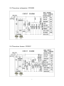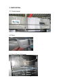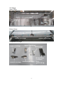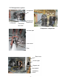
1
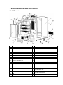
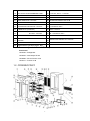
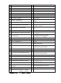
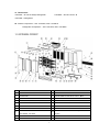
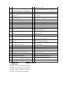
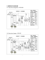
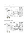
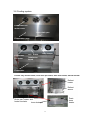
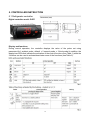
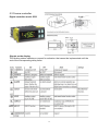
COMMERCIAL
REFRIGERATOR & FREEZER
SERVICE MANUAL
(CFD Units)
MODEL: CFD-1RR
CFD-2RR
CFD-3RR
CFD-1FF
CFD-2FF
CFD-3FF
TABLE OF CONTENTS
1. EXPLODED VIEW AND PARTS LIST
1.1 CFD1 series
1.2 CFD2 series
1.3 CFD3 series
2.WIRING DIAGRAM
2.1 One door refrigerator: CFD1RR
2.2 One door freezer: CFD1FF
2.3 Two door refrigerator: CFD2RR
2.4 Two door freezer: CFD2FF
2.5 Three door refrigerator: CFD3RR
2.6 Three door freezer: CFD3FF
3.PART DETAIL
3.1 Control panel
3.2 Door
3.3 Shelf &Track & Bracket
3.4 Hinge
3.5 Refrigeration system
3.6 Cooling system
4. SUMMARY OF MAIN PARTS
5. CONTROLLER INSTRUCTION
5.1 Refrigerator controller
5.2 Freezer controller
6. REPLACEMENT OF THE MAIN PARTS
6.1 Control panel component
6.2 Door and hinge
6.3 Cooling system
6.4 Refrigeration system
6.5 Others
7. CLEANING AND MAINTENANCE
7.1 Cleaning
7.2 Maintenance
1
2
2-3
3-4
5-6
7
7
7
8
8
9
9
10
10
10
10
11
12
13
14-16
17
17-18
19-22
23
23-24
25-28
29-32
33
34-37
38
38-39
39
1. EXPLODED VIEW AND PARTS LIST
1.1 CFD1 series
1
CABINET: N/A
30
DOOR SWITCH: 17817409
2
CONTROL PANEL ★★
31
LOCK: 17813009
3
FRONT GRILL
32
4" CASTOR WITH BRAKE: 17816412
4
UPPER RIGHT HINGE: 178HINGCFDTR
33
4" CASTOR: 17819301
5
BOTTOM RIGHT HINGE:178HINGCFDBR
34
DRAIN PLUG ★★
6
SPRING HINGE: 178CARTRIDGE
35
FOAMING HOLE COVER: N/A
7
TOP COVER FOR REVERSIBLE DOOR
36
DRAIN HOSE
8
BOTTOM COVER FOR REVERSIBLE DOOR
37
LIGHT COMPONENTS: 17819014
9
DOOR: 17815080
38
POWER CORD: 17810175
10
GASKET: 178GSKT11571
39
COMPRESSOR UNIT INSTALLATION BOARD: N/A
11
BRACKETS: 17818644
40
CONDENSER: 17815157 or (17818779 ★)
12
LEFT SHELF TRACK: 178SHELFRAIL
41
CONDENSER FAN MOTOR: 17814905
13
RIGHT SHELF TRACK: 178SHELFRAIL
42
CONDENSER FAN COVER: 1785467
14
SHELF: 178SHELFCFD
43
CONDENSER FAN MOTOR BLADE: 17811089
RIGHT CONNECTING BOARD FOR CASTER
15
★★
44
LEFT CONNECTING BOARD FOR CASTER
16
★★
45
17
LEG SUPPORTER ★★
46
2
FILTER FIXER: N/A
FILTER: 970C032CAPT
OUTER DRAIN PAN: 17816356
COMPRESSOR: Ref – 17817554, Old F –
18
LEFT TRACK FOR ASSEMBLING PANEL
47
17811567, New F – 17811460
19
RIGHT TRACK FOR ASSEMBLING PANEL
48
SPLICE BOX ★★
20
EVAPORATOR: 17811872
49
START CAPACITOR ★★
21
INNER DRAIN PAN: 17815065
50
OVERLOAD PROTECTOR ★★
22
FAN MOTOR INSTALLATION PANEL ★★
51
STARTER ★★
TEMPERATURE SENSOR OF CABINET INSIDE:
23
EVAPORATOR FAN MOTOR: 17813407
52
17813890 SF ONLY
24
THERMOSTAT (See Below)
53
KEY: 17811836
POWER SWITCH: Old Green – 17810364
25
26
EVAPORATOR TEMPERATURE SENSOR
New Red-- 17810365
EVAPORATOR COVER: 17818696
54
★:17813890 SF ONLY
55
DRAIN PAN HEATER ★:17815641
EVAPORATOR FAN MOTOR COVER:
27
17815699
56
28
BACK GRILL ★★
57
29
COMPONENTS FOR BACK SHELF ★★
★ Freezer only ★★ Consult Factory
Thermostat:
17815350 – Refrigerator
17816023 – with Relays SF102
17818869 – SF104 Freezer ★★
17819471 – Freezer ★★
1.2 CFD2RR/CFD2FF
3
DRAIN HOSE HEATER ★: 17813722
DEFROST HEATER ★:17813517
1
CABINET: N/A
33
LOCK: 17813009
2
CONTROL PANEL
34
DOOR SWITCH: 17817409
3
FRONT GRILL ★★
35
BACK GRILL
4
RIGHT DOOR: 17818904
36
COMPONENTS FOR BACK SHELF
5
GASKET: 178GSKT10521
37
4" CASTOR WITH BRAKE: 17816412
6
UPPER RIGHT HINGE: 178HINGCFDTR
38
4" CASTOR: 17819301
7
BOTTOM RIGHT HINGE: 178HINGCFDBR
39
DRAIN PLUG: 17813588
8
SPRING HINGE: 178CARTRIDGE
40
FOAMING HOLE COVER: N/A
9
LEFT DOOR: 17818904
41
DRAIN HOSE
10
GASKET: 178GSKT10521
42
11
UPPER LEFT HINGE: 178HINGCFDTL
43
12
LEFT BOTTOM HINGE: 178HINGCFDBL
44
13
SPRING HINGE: 178CARTRIDGE
45
14
BRACKET
46
15
MIDDLE BRACKET: 17815961 Support Rack
47
16
BACK BRACKET
48
17
LEFT SHELF TRACK: 178SHELFRAIL
49
CONDENSER FAN COVER: 1785467
18
RIGHT SHELF TRACK: 178SHELFRAIL
50
FILTER FIXER: N/A
19
SHELF: 178SHELFCFD
51
FILTER
52
OUTER DRAIN PAN
53
COMPRESSOR (See Note Below)
20
21
RIGHT CONNECTING BOARD FOR CASTER
★★
LEFT CONNECTING BOARD FOR CASTER
★★
LIGHT COMPONENTS: 17819014 (Cover For
Lights)
POWER CORD: 17810175
TEMPERATURE SENSOR OF CABINET INSIDE:
17813890 – SF ONLY
COMPRESSOR UNIT INSTALLATION BOARD:
N/A
CONDENSER: 17811539
CONDENSER FAN MOTOR: R – 17810976
F -- 17815815
CONDENSER FAN MOTOR BLADE:
R – 17817114
F -- 17812660
22
LEG SUPPORTER ★★
54
SPLICE BOX ★★
23
LEFT TRACK FOR ASSEMBLING PANEL ★★
55
STARTER ★★
56
OVERLOAD PROTECTOR ★★
24
RIGHT TRACK FOR ASSEMBLING PANEL
★★
25
EVAPORATOR: 17816999
57
START CAPACITOR ★★
26
INNER DRAIN PAN: 17817891
58
KEY: 17811836
27
FAN MOTOR INSTALLATION PANEL ★★
59
SUPPORT ROD
28
EVAPORATOR FAN MOTOR: 17813407
60
29
EVAPORATOR COVER: 17816883
61
DRAIN PAN HEATER★
62
DRAIN HOSE HEATER★ 17813722
63
DEFROST HEATER★ 17817764
30
31
32
EVAPORATOR FAN MOTOR COVER:
17818696
THERMOSTAT (See Below)
POWER SWITCH: Old Green – 17810364
★Freezer only
64
New Red -- 17810365
★★ Consult Factory
4
EVAPORATOR TEMPERATURE SENSOR★
17813890 (SF Only)
17815642
31. Thermostats:
17816023 – SF102 w/ Relays Refrigerator
17818846 – SF104 Freezer ★
17815350 – Refrigerator
53. Freezer Compressor – Old: 17812874, New: 17818018
Refrigerator Compressor – Old: 17817533, New: 17818892
1.3 CFD3RR/ CFD3FF
1
CABINET: N/A
35
DOOR SWITCH: 17817409
2
CONTROL PANEL: 17817125
36
BACK GRILL
3
FRONT GRILL
37
COMPONENTS FOR BACK SHELF ★★
4
RIGHT DOOR: 17818904
38
4" CASTOR WITH BRAKE: 17816412
5
GASKET: 178GSKT10521
39
4" CASTOR: 17819301
6
UPPER RIGHT HINGE: 178HINGCFDTR
40
DRAIN PLUG: 17813588
7
SPRING HINGE: 178CARTRIDGE
41
FOAMING HOLE COVER: N/A
8
BOTTOM RIGHT HINGE: 178HINGCFDBR
42
DRAIN HOSE
9
43
LEFT DOOR: 17818904
LIGHT COMPONENTS: 17819014 (Cover For
Lights)
10
GASKET: 178GSKT10521
44
POWER CORD
11
UPPER LEFT HINGE: 178HINGCFDTL
45
TEMPERATURE SENSOR OF CABINET INSIDE:
5
17813890 -- SF Only
12
13
14
15
46
LEFT BOTTOM HINGE: 178HINGCFDBL
SPRING HINGE: 178 CARTRIDGE
47
48
BRACKETS
49
MIDDLE BRACKETS
COMPRESSOR UNIT INSTALLATION BOARD:
N/A
CONDENSER: R-17811539, F-17817943
CONDENSER FAN MOTOR: R-17810976,
F-17810727
BLADE OF CONDENSER FAN MOTOR:
R-17817114, F-17812660
16
BACK BRACKETS
50
CONDENSER FAN COVER: 17812098
17
LEFT SHELF TRACK: 178SHELFRAIL
51
FILTER FIXER: N/A
18
RIGHT SHELF TRACK: 178SHELFRAIL
52
FILTER
19
SHELF: Left or Right – 178SHELFCFD
53
CONDENSATE DRAIN PAN: 17812622
20
MIDDLE SHELF: 178SHELFCFD3
54
COMPRESSOR: R-17815901, F-17818299
21
22
23
24
25
26
RIGHT CONNECTING BOARD FOR CASTER
★★
LEFT CONNECTING BOARD FOR CASTER
55
56
★★
LEG SUPPORTER ★
57
LEFT TRACK FOR ASSEMBLING PANEL
58
★★
RIGHT TRACK FOR ASSEMBLING PANEL
59
★★
60
EVAPORATOR: 17810051
SPLICE BOX ★★
STARTER ★★
OVERLOAD PROTECTOR ★★
START CAPACITOR ★★
AC CONTACTOR: 17819644
BOTTOM HINGE FOR MIDDLE DOOR:
178HINGCFDBM
27
INNER DRAIN PAN: 17811448
61
MIDDLE DOOR BLOCK: N/A
28
FAN MOTOR INSTALLATION PANEL ★
62
KEY: 17811836
29
EVAPORATOR FAN MOTOR: 17813407
63
SUPPORT ROD ★★
30
64
EVAPORATOR COVER: 17818904
EVAPORATOR TEMPERATURE SENSOR★
17813890 – SF Only
31
EVAPORATOR FAN COVER: 17815699
65
DRAIN PAN HEATER: 17815643 ★
32
THERMOSTAT (See Below)
66
DRAIN HOSE HEATER: 17813722 ★
67
DEFROST HEATER: 17817359★
33
34
POWER SWITCH: Green Old – 17810364
Red New - 17810365
LOCK: 13009
★Freezer only
68
★★ Consult Factory
32. Thermostats:
17816023 – SF 102, Refrigerator Thermostat
17818846 – SF104, Freezer Thermostat★
17815350 – Carenl Refrigerator Thermostat
17819471 – Carel Freezer Thermostat★
6
2. WIRING DIAGRAM
2.1 One door refrigerator: CFD1RR
2.2 One door freezer: CFD1FF
7
2.3 Two door refrigerator: CFD2RR
2.4 Two door freezer: CFD2FF
8
2.5 Three door refrigerator: CFD3RR
2.6 Three door freezer: CFD3FF
9
3. PART DETAIL
3.1 Control panel
Brand
Thermostat
Power Switch
Lock
Door Switch
Key
3.2 Door
Door Gasket
3.3 Shelf &Track & Bracket
Component
for back shelf
Light
Component
Left Shelf Track
Bracket
Back Bracket
Right Shelf Track
Left Shelf
Track
Shelf
Middle
Bracket
10
3.4 Hinge
Upper Hinge
Thermostat
Upper
Left
Hinge
Upper
Right
Hinge
Control Panel
Bottom Hinge
Bottom Left Hinge
Bottom Right Hinge
Comparison Of Hinge
Upper Left Hinge
Bottom Left Hinge
Upper Right Hinge
Spring Hinge
Bottom Right Hinge
11
Bottom Hinge
For Middle
Door
(CFD3 ONLY)
3.5 Refrigeration system
Compressor
Condenser
Compressor
component
Condenser
fan motor
Condenser
fan motor
cover
Compressor component
Out drain pan
Filter mount
Filter
Drain hose
Suction pipe
Support rod
Leg support
Installation
board
12
3.6 Cooling system
Evaporator fan
motor cover
Inner drain pan
Evaporator cover
Evaporator
fan motor
Fan motor
installation
board
Temp sensor
Evaporator
Freezer only: defrost heater, inner drain pan heater, drain hose heater, defrost sensor
Defrost
heater
Defrost
sensor
Drain
hose
heater
Drain pan heater and
heater insulator
Inner drain pan
13
5. CONTROLLER INSTRUCTION
5.1 Refrigerator controller
Digital controller model: PJEZ
Display and functions
During normal operation, the controller displays the value of the probe set using
parameter/4(=1 ambient probe, default, = 2 second probe, = 3 third probe).In addition, the
display has LEDs that indicate the activation of the control functions (see Table 1),while the
3 buttons can be used to activate/deactivate some of the functions (see Table 2).
14
Setting the set point (desired temperature)
1. press SET for 1 second, the set value will start flashing after a few moments;
2. increase or decrease the value using UP or DOWN;
3. press SET to confirm the new value.
Switching the device ON/OFF
Press UP for more than 3 seconds. The control and defrost algorithms are now disabled
and the Instrument displays the message “OFF” alternating with the temperature read by
the set probe.
Manual defrost
Press for DOWN more than 3 seconds (the defrost starts only if the temperature conditions
are valid).
Continuous cycle
Press UP and DOWN together for more than 3 seconds.
Access and setting type F (frequent) and type C (configuration) parameters
1. Press SET for 3 seconds (the display will show ”PS”);
2.To access the type F and C parameter menu, press SET, enter the password “22”
using UP/DOWN, press SET to confirm;
To access the F parameter menu only, press SET (without entering the password);
3. Scroll inside the parameter menu using UP/DOWN;
4. To display/set the values of the parameter displayed, press SET, then UP/DOWN and
finally SET to confirm the changes (returning to the parameter menu).
To save all the new values and exit the parameter menu, press SET for 3 seconds;
To exit the menu without saving the changed values (exit by timeout) do not press any
button for at least 60 seconds.
15
5.2 Freezer controller
Digital controller model: IR33
Signals on the display
The blinking status indicates a request for activation that cannot be implemented until the
end of the corresponding delay times.
16
Setting the set point (desired temperature value)
To display or change the set point, proceed as follow:
1. Press the “Set” button for more than 1 second to display the set point;
2. Increase or decrease the value of the set point, using the “
“ and “
until reaching the desired value;
3. Press the “Set” button again to confirm the new value.
Alarms with manual reset
Alarms with manual reset can be reset by pressing the “
5 seconds.
“ and “ “
“ respectively,
“ for more than
Manual defrost
As well as the automatic defrost function, a manual defrost can be enabled, if the
temperature conditions allow, by pressing the”
“ button for more than 5 seconds.
Continuous cycle
Pressing the buttons “
“ and “
“ simultaneously for more than 5 seconds enable
the continuous cycle function.
During operation in continuous cycle, the compressor continues to operate for the time “cc”
and it stops when reaches the “cc” time out or the minimum temperature envisaged (AL =
minimum temperature alarm threshold).
Continuous cycle setting: “cc” parameter (continuous cycle duration):”cc”=0 never
active;”c6” parameter (by passing the alarm after the continuous cycle):”cc” = 0 never
active; it avoid or delays the low temperature alarm after the continuous cycle.
Accessing the configuration parameter (type C)
1. Pressing the “
“ and “Set” buttons at the same time for more than 5 seconds, the
display will show “00”(password prompt).
2. Press “Set”, use the “
“ “ or “
“ buttons to display the number “22” (parameter
access password).
3. Confirm by pressing “Set”.
4. The display will show the first modifiable “C” parameter.
Accessing the configuration parameter (type F)
1. Hold the “
“ button for more than 5 seconds (if there are active alarms, first mute the
buzzer), the display will show the first modifiable “F” parameter.
Modifying the parameters
After having displayed the parameter, either type “C” or type “F”, proceed as follows:
1. Use the “
“ or “
“ buttons to scroll the parameters until the parameter to be
modified is reached. When scrolling the parameters, an icon is shown on the display that
represents the category of the parameter.
17
2. Alternatively, press the“
“button to display a menu that can be used to quickly access
the group of parameters to be modified.
3. Scrolling the menu using the “
“and “
“buttons displays the codes of the
various categories of parameters, accompanied by the corresponding icon on the display
(if present).
4. Once having reached the desired category, press “Set” to go directly to the first
parameter in the chosen category (if no parameter is visible, pressing the “Set” button will
have no effect)
5. At this stage, modify the parameters or return to the “Category” menu, using the
“
“button.
6. Press ”Set” to display the value associated with the parameter.
7. Increase or decrease the value using the “
“ or “
“ buttons respectively.
8. Press “Set” to temporarily save the new value and return to the display of the parameter.
9. Repeat the operation from point 1 or point 2.
10. If the parameter has sub-parameters, press “Set” to display the first sub-parameter.
11. Press the “
“or “
“ button to display all the sub-parameters.
12. Press “Set “to display the associated value.
13. Increase or decrease the value using the “
“ or “
“button respectively.
14. Press “Set” to temporarily save the new value and return to the display of the
sub-parameter code.
15. Press “
“ to return to the display of the parent parameter.
Saving the new values assigned to the parameter
To permanently save the new values of the modified parameters, press the “
“ button
for more than 5 seconds, thus exiting the parameter setting procedure. All the
modifications made to the parameters temporarily saved in the RAM can be canceled and
“normal operation” is resumed by not pressing any buttons for 60 seconds. All the
modifications made to the parameters that were temporarily saved will be lost.
18
Correct Settings for CAREL Controllers (115V)
MODE
PJEZ(REFRIG)
IR33(FREEZER)
DISPLAY
/5
1
1
TEMPERATURE UNIT F/C
/c1
0
0
CABINET OFFSET
/c2
0
0
EVAP OFFSET
St
33
-7
USER SET POINT
rd
7
7
DIFFERENTIAL
r1
33
-10
LOW LIMIT
r2
43
10
HIGH LIMIT
c0
2
2
COMPRESSOR DELAY
dI
3
3
DEFROST INTERVAL TIME
dt1
43
58
DEFROST TERMINATION TEMP
dP1
20
20
MAX DEFROST DURATION
F0
N/A
2
FAN OPERATING FUNCTION
F1
N/A
41
FAN STARTING TEMPERATURE
F2
N/A
1
FAN STOPS WHEN COMPRESSOR STOPS
F3
N/A
1
FAN MODE DURING DEFROSTING
19
6. REPLACEMENT OF THE MAIN PARTS
CAUTION!!!
Before beginning, make sure the device has been disconnected
from the power socket (pull the power plug) and has been cooled
down.
6.1 Control panel components
-Control panel
-Thermostat
-Power switch
-Door switch
-Lock and key
A. Unscrew the screws located on the bottom of the control panel
B. Turn up the control panel and place that on the top of the cabinet. You can
replace the controller, power switch, lock, door switch here.
20
C. You can also unscrew the screws located on the top of the control panel.
Remove the control panel from the cabinet to replace the parts: controller,
power switch, lock, door switch and the control panel.
CAUTION!!! When screwing in the screw, please hold the control panel to
prevent it from falling off and scratching the cabinet.
D. To reassemble, reverse the order of the instructions.
21
6.2 Door and hinge
A. Disassemble control panel as described above
B. Unscrew the screws located on each side of the front grill and remove the
front grill
C. Unscrew the upper hinge. Unscrew the last screw while holding onto the
door. You can replace the upper hinge and spring hinge here.
22
D. Unscrew the lower hinge
CAUTION!!! The door should be lifted by another person when unscrewing the
lower hinge to avoid accident.
E. Take off the door and you can replace the upper/lower/spring hinge and
door here.
Upper hinge
Lower hinge
Spring hinge
F. To reassemble the door, reverse the order of instructions. Assemble the
lower hinge while lifting the door, and then assemble the upper hinge.
G. If you want to replace the door gasket. Take off the gasket and assemble a
new one by using a soft hammer to ensure proper alignment in the channel.
Clean the gasket with a damp, soft cloth and then dry with a clean cloth.
23
◆ Reversible door, CFD1 Model only.
A. Disassemble the control panel, front grill, hinges and door as described
above.
B. Rotate the door 180 degrees, attach the upper and lower hinge to the door.
For example: The door was assembled with an upper right hinge and lower
right hinge, after removing the hinge and rotating 180 degrees, the door should
be assembled with an upper left hinge and lower left hinge.
C. Mount the door onto the cabinet
24
D. Take the top cover for the reversible door from the left side of the control
panel to the right side.
Take the bottom cover for the reversible door from the left side of the front
grill to the right side.
E, Assemble the control panel and the front grill. The left-hinged model is now
a right-hinged.
Left Hinged
Right Hinged
25
6.3 Cooling system
-Evaporator/evaporator cover/Temperature sensor
-Evaporator fan motor/fan motor cover
-Inner drain pan
-Defrost heater/drain pan heater/drain hose heater/defrost sensor (freezer
only)
A. To replace the evaporator fan motor cover, unscrew the screws and replace
with a new cover.
B. Unscrew the screws located on each side of the evaporator fan cover (left,
right and front).You can replace the evaporator fan cover and inner drain pan
here.
Evaporator
fan cover
Inner drain pan
(refrigerator only)
26
C. The evaporator components are as pictured.
Refrigerator
Freezer
D. Unscrew the screws located on the fan motor installation board and
temperature sensor mount. You can replace fan motor and temperature senor
here.
27
E. Unscrew the screws located on each side of the inner drain pan. Disconnect
the cable connectors. You can replace inner drain pan, drain pan heater and
drain hose heater here. (Freezer model only)
F. Here is the evaporator unit after removing the fan motor and inner drain pan.
(Freezer model only)
Defrost
sensor
Defrost
heater
G. Snip the pins used to mount the defrost heater. Disconnect the cable
connector. You can replace the defrost heater now. Also use the pins to mount
the defrost heater when installing the new one. (Freezer model only)
28
H. Remove evaporator fan motor and fan motor installation board. Unscrew
the screws located on each side of the evaporator. You can replace the
evaporator here.
I. To reassemble the evaporator component, complete steps in reverse order.
L. If you want to replace the temperature sensor and defrost sensor, the control
panel must also be disassembled.
29
6.4 Refrigeration system
-Compressor/compressor components
-Condenser/condenser fan motor/blade/cover
-Outer drain pan
-Filter
A. Unscrew the screws located on both side of the front grill and remove that.
B. Unscrew the screw used to mount the compressor unit installation board.
C. Pull-out the compressor component, you can replace and clean the parts
here.
30
6.5 Others
-Lamp component
-Power cord/back grill/AC contactor
-Shelf and shelf rail component
1. Lamp component
Unscrew the screws used to mount the lamp component and install a new
one.
2. Power cord & back grill & AC contactor
A. Unscrew the screws located on each side of the back grill.
B. Remove the back grill. Unscrew the screws used to mount the power cord
connector. You can install a new power cord here.
31
C. Unscrew the screw used to mount the AC contactor (Model CFD-3FF
ONLY)
CAUTION!!! Please make sure the device is unplugged when you replace
the power cord and AC contactor.
3. Shelf & shelf rail component.
A. Pull the shelf out, you can replace or clean the shelf here or put a full-sized
food pan on the rails.
B. Replace and clean the shelf rail. Pull upward and outside the shelf rail.
Front side of the rail
Rear side of the rail
One Pair
32
C. Lift up on the front bracket (channel), you can replace and clean it here.
D. Unscrew the screws used to mount the back component.
E. Assemble the bracket (channel) by lining up the screw with the mounting
bracket and pushing down on the bracket (channel) until secure.
33
F. Install the shelf rail by lining up the clips on the rail with the holes on the
bracket and pushing down.
I. Clean the shelf with an appropriate disinfecting agent.
34
7. CLEANING AND MAINTENANCE
7.1 Cleaning
CAUTION!!! Before cleaning the cabinet, ensure it is disconnected from the
main power supply.
A. Clean exterior and interior of the device with a damp and soft cloth. Dry and
polish the device with a soft and dry cloth after cleaning.
B. Use a vacuum cleaner and soft brush to carefully clean the surface of the
condenser unit.
35
Tips for cleaning
1. Clean the unit regularly.
2. Never use harsh cleaning substances such as scouring powder or cleaners
containing alcohol or solvents that could damage the device’s surface.
3. To prevent cooling problems, clean the condenser regularly.
4. Never use a stiff brush to clean the unit.
5. Do not pressure wash the unit.
7.2 Maintenance
1. Clean the exterior and interior of the unit and condenser unit monthly.
2. Check the main power cable for damage regularly. Never operate the device
if the cable is damaged. A damaged cable must immediately be replaced by
customer service or a qualified electrician.
3. In case of damage or malfunction, please contact our customer service
center at 1-800-678-5517.
4. If the unit is not going to be used for a long period time, unplug the unit and
remove the food. Clean and dry the unit thoroughly.
5. Only a qualified technician using OEM replacement parts and accessories
should carry out repairs and maintenance of the unit. Do not attempt to repair
the unit yourself.
36