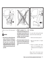
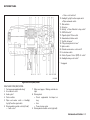
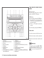
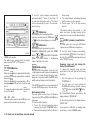
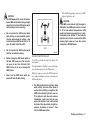
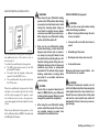
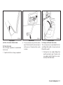
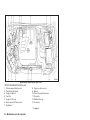
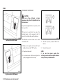
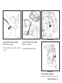
1
Foreword Welcome to the growing family of new NISSAN owners. This vehicle has been delivered to you with confidence. It has been produced using the latest techniques and strict quality control. This manual was prepared to help you understand the operation and maintenance of your vehicle so that you may enjoy many kilometers (miles) of driving pleasure. Please read through this manual before operating your vehicle. A separate Warranty Information & Maintenance Booklet explains details about the warranties covering your vehicle. A NISSAN dealer knows your vehicle best. When you require any service or have any questions, we will be glad to assist you with the extensive resources available for you. IMPORTANT SAFETY INFORMATION REMINDERS FOR SAFETY! MODIFICATION OF YOUR VEHICLE Follow these important driving rules to help ensure a safe and complete trip for you and your passengers! This vehicle should not be modified. Modification could affect its performance, safety or durability, and may even violate governmental regulations. In addition, damage or performance problems resulting from modifications may not be covered under NISSAN warranties. ● ● ● ● ● NEVER drive under the influence of alcohol or drugs. ALWAYS observe posted speed limits and never drive too fast for conditions. ALWAYS use your seat belts and appropriate child restraint systems. Preteen children should be seated in the rear seat. ALWAYS provide information about the proper use of vehicle safety features to all occupants of the vehicle. ALWAYS review this Owner’s Manual for important safety information. WHEN READING THE MANUAL This manual includes information for all options available on this model. Therefore, you may find some information that does not apply to your vehicle. All information, specifications and illustrations in this manual are those in effect at the time of printing. NISSAN reserves the right to change specifications or designs without notice and without obligation. READ FIRST — THEN DRIVE SAFELY Before driving your vehicle, read this Owner’s Manual carefully. This will ensure familiarity with controls and maintenance requirements, assisting you in the safe operation of your vehicle. Throughout this manual we have used the symbol followed by the word WARNING. This is used to indicate the presence of a hazard that could cause death or serious personal injury. To avoid or reduce the risk, the procedures must be followed precisely. The symbol followed by the word CAUTION is also used throughout this manual to indicate the presence of a hazard that could cause minor or moderate personal injury or damages to your vehicle. To avoid or reduce the risk, the procedures must be followed carefully. ON-PAVEMENT AND OFF-ROAD DRIVING This vehicle will handle and maneuver differently from an ordinary passenger car, because it has a higher center of gravity for off-road use. As with other vehicles with features of this type, failure to operate this vehicle correctly may result in loss of control or an accident. Be sure to read the “ON-PAVEMENT AND OFFROAD DRIVING PRECAUTIONS” in the “5. Starting and driving” section of this manual. SIC0697 If you see this symbol, it means “Do not do this” or “Do not let this happen” . If you see a symbol similar to these in an illustration, it means the arrow points to the front of the vehicle. Arrows in an illustration that are similar to these indicate movement or action. Arrows in an illustration that are similar to these call attention to an item in the illustration. © 2013 NISSAN MOTOR (THAILAND) CO., LTD. Table of contents Illustrated table of contents 0 Safety — seats, seat belts and supplemental restraint system 1 Instruments and controls 2 Pre-driving checks and adjustments 3 Heater and air conditioner, and audio system 4 Starting and driving 5 In case of emergency 6 Appearance and care 7 Maintenance and do-it-yourself 8 Technical information 9 Index 10 0 Illustrated table of contents Seats, seat belts and Supplemental Restraint System (SRS) ......................................................................... Exterior front ............................................................................ Exterior rear ............................................................................. Passenger compartment ....................................................... Instrument panel ..................................................................... Left-Hand Drive (LHD) model ......................................... 0-2 0-3 0-4 0-5 0-6 0-6 Right-Hand Drive (RHD) model ....................................... 0-7 Engine compartment .............................................................. 0-8 YD25DDTi engine model (LHD model) ......................... 0-8 YD25DDTi engine model (RHD model) ........................ 0-9 QR25DE engine model .................................................. 0-10 SEATS, SEAT BELTS AND SUPPLEMENTAL RESTRAINT SYSTEM (SRS) SSI0280 Left-hand drive (LHD) Double Cab model 1. Rear seats (folding)* (Double Cab model) (P. 6-3) Jump seat* (King Cab model) (P. 1-4) 2. Head restraints (P. 1-4) 3. Front seats (P. 1-2) 4. Supplemental front impact air bags* (P. 1-21) 5. Seat belts (P. 1-5) 6. Pre-tensioner seat belt system * (P. 1-27) *: if equipped 0-2 Illustrated table of contents EXTERIOR FRONT JVC0446X 1. 2. 3. 4. 5. 6. Double Cab model Hood (P. 3-9) 7. Fog lights* (P. 2-20) Windshield wiper and washer 8. Headlights and turn signals — Wiper and washer switch (P. 2-21) — Headlight and turn signal switch (P. 2-18) — Wiper maintenance (P. 8-24) — Bulb replacement (P. 8-27) — Washer fluid (P. 8-18) 9. Tires Roof rack* (P.2-28) — Tires and wheels (P. 8-32) Power windows* (P. 2-23) — Flat tire (P. 6-2) Recovery hook (Left-Hand Drive model) — Specifications (P. 9-7) (P.6-15) 10. Side turn signal light Recovery hook (Right-Hand Drive model) — Switch operation (P.2-20) (P. 6-15) — Bulb replacement (P.8-27) 11. Outside rearview mirrors (P. 3-12) 12. Doors — Keys (P. 3-2) — Door locks (P. 3-2) — Remote keyless entry system* (P. 3-5) *: if equipped Illustrated table of contents 0-3 EXTERIOR REAR JVC0447X Double Cab model 5. Fuel filler lid — Operation (P. 3-10) — Fuel recommendation (P. 9-4) 6. Rear combination light (Bulb replacement) (P. 8-27) 1. High-mounted stop light* — Bulb replacement (P.8-27) 2. Rear window — Defogger switch* (P.2-22) 3. Truck box (P. 3-14) 4. Rear doors* — Child safety rear door locks (Double Cab model) (P. 3-5) — Rear access doors (King Cab model) (P. 3-4) 0-4 Illustrated table of contents *: if equipped PASSENGER COMPARTMENT JVC0456X Left-hand drive (LHD) Double Cab model 1. Microphone* — Bluetooth Hands-Free phone system (P.4-27) 2. Map lights* (P. 2-29) 3. Sun visors (P. 2-28) 4. Inside rearview mirror — Adjustment (P. 3-11) — Compass operation* (P. 2-9) 5. Jacking equipment (P. 6-3) 6. Rear cup holders* (P. 2-27) 7. Console box* (P. 2-26) 8. Front cup holders* and ashtray* (P. 2-27) *: if equipped Illustrated table of contents 0-5 INSTRUMENT PANEL 10. Air conditioner control (P. 4-2) 11. Front passenger supplemental front-impact air bag* (P. 1-26) 12. Diesel Particulate Filter (DPF) regeneration switch* (P.5-6) 13. Headlight aiming control switch* (P. 2-19) 14. Hood release switch (P. 3-9) 15. Outside rearview mirror control switch* (P. 3-12) 16. Fuel filler lid opener* (P. 3-10) 17. Tilting steering wheel lock lever* (P. 3-10) 18. Ignition switch (P. 5-7) 19. Hazard indicator flasher switch (P. 2-22) 20. 4WD shift switch* (P. 5-20) 21. Ashtray* (P. 2-25) 22. Cigarette lighter* (P. 2-25)/Power outlet (P. 2-24) 23. Glove box (P. 2-26) *: if equipped JVC0431X Left-hand drive (LHD) model LEFT-HAND DRIVE (LHD) MODEL 1. Side ventilator (P. 4-2) 2. Headlight, fog light* and turn signal switch (P. 2-18) 3. Steering-wheel-mounted controls (left side) — Audio control* (P.4-15) 4 Steering wheel — Driver’s supplemental front-impact air bag* (P. 1-21) 0-6 Illustrated table of contents 5. 6. 7. 8. 9. — Horn (P. 2-22) — Power steering system (P. 5-34) Meters and gauges (P. 2-4)/Warning and indicator lights (P. 2-12) Steering-wheel-mounted controls (right side) — Cruise control switches* (P.5-25) Wiper and washer switch (P. 2-21) Center ventilator (P. 4-2) Audio system* (P. 4-8) INSTRUMENT PANEL 10. Headlight, fog light* and turn signal switch (P. 2-18) or Wiper and washer switch (P.2-21) 11. Side ventilator (P. 4-2) 12. Glove box (P. 2-26) 13. Ashtray* (P. 2-25) or Rear differential locking switch* (P.5-25) 14. 4WD shift switch* (P. 5-20) 15. Cigarette lighter* (P. 2-25)/Power outlet (P. 2-24) 16. Hazard indicator flasher switch (P. 2-22) 17. Fuel filler lid opener* (P. 3-10) 18. Tilting steering wheel lock lever* (P. 3-10) 19. Ignition switch (P. 5-7) 20. Outside rearview mirror control switch* (P. 3-12) 21. Hood release switch (P. 3-9) 22. Vehicle Dynamic Control (VDC) off switch* (P. 5-34) 23. Headlight aiming control switch* (P. 2-19) *: if equipped JVC0432X Right-hand drive (RHD) model RIGHT-HAND DRIVE (RHD) MODEL 1. Front passenger supplemental air bag* (P. 1-26) 2. Air conditioner control (P. 4-2) 3. Audio system* (P. 4-8) 4. Center ventilator (P. 4-2) 5. Wiper and washer switch (P. 2-21) or Head light, fog light* and turn signal switch (P.2-18) 6. Steering-wheel-mounted controls (left side) — Audio control* (P.4-15) 7. Meters and gauges (P. 2-4)/Warning and indicator lights (P. 2-12) 8. Steering wheel — Driver’s supplemental front-impact air bag (P. 1-21) — Horn (P. 2-22) — Power steering system (P. 5-34) 9. Steering-wheel-mounted controls (right side) — Cruise control switches* (P.5-25) Illustrated table of contents 0-7 ENGINE COMPARTMENT SSI0442 Left-hand drive (LHD) model (with engine cover*) YD25DDTi ENGINE MODEL (LHD model) 1. Window washer fluid reservoir (P. 8-18) 2. Fuse/fusible link holder (P. 8-26) 3. Engine oil dipstick (P. 8-9) 4. Fuel filter (P. 8-14) 5. Engine oil filler cap (P. 8-10) 6. Brake and clutch fluid reservoir* (P. 8-17) 7. Sedimentor* (P. 8-15) 0-8 Illustrated table of contents 8. Engine coolant reservoir (P. 8-8) 9. Battery (P. 8-19) 10. Power steering fluid reservoir (P. 8-16) 11. Drive belts (P. 8-22) 12. Radiator filler cap (P. 8-8) 13. Air cleaner (P. 8-23) *: if equipped SSI0443 Right-hand drive (RHD) model (with engine cover*) YD25DDTi ENGINE MODEL (RHD model) 1. Window washer fluid reservoir (P. 8-18) 2. Fuse/fusible link holder (P. 8-26) 3. Brake and clutch fluid reservoir* (P. 8-17) 4. Engine oil dipstick (P. 8-9) 5. Fuel filter (P. 8-14) 6. Engine oil filler cap (P. 8-10) 7. Sedimentor* (P. 8-15) 8. Engine coolant reservoir (P. 8-8) 9. Battery (P. 8-19) 10. Power steering fluid reservoir (P. 8-16) 11. Drive belts (P. 8-22) 12. Radiator filler cap (P. 8-8) 13. Air cleaner (P. 8-23) *: if equipped Illustrated table of contents 0-9 SSI0335 Left-hand drive (LHD) model QR25DE ENGINE MODEL 1. Window washer fluid reservoir (P. 8-18) 2. Fuse/fusible link box (P. 8-26) 3. Air cleaner (P. 8-23) 4. Engine oil filler cap (P. 8-12) 5. Engine oil dipstick (P. 8-9) 6. Brake fluid reservoir/Clutch fluid reservoir (P. 8-17) 7. Drive belts (P. 8-22) 0-10 Illustrated table of contents 8. 9. 10. 11. Radiator cap (P. 8-8) Power steering fluid reservoir (P. 8-16) Battery (P. 8-19) Engine coolant reservoir (P. 8-8) 1 Safety — seats, seat belts and supplemental restraint system Seats.......................................................................................... 1-2 Front seats............................................................................ 1-2 Jump seat (King Cab model)............................................ 1-4 Head restraints.................................................................... 1-4 Seat belts.................................................................................. 1-5 Precautions on seat belt usage........................................ 1-5 Child safety........................................................................... 1-8 Pregnant women.................................................................. 1-8 Injured persons..................................................................... 1-8 Center mark on seat belts (if equipped)......................... 1-9 Three-point type seat belts................................................ 1-9 Two-point type seat belts (if equipped).......................... 1-11 Seat belt maintenance....................................................... Child restraints (for Australia)............................................... Child restraints (except for Australia)................................. Precautions on child restraints usage ........................... Installation of child restraint system ............................... Supplemental Restraint System (SRS) (if equipped) ............................................................................ Precautions on Supplemental Restraint System (SRS) ................................................................................... Supplemental air bag systems ........................................ Pre-tensioner seat belt system (if equipped) ............... Repair and replacement procedure ............................... 1-12 1-13 1-13 1-13 1-14 1-21 1-21 1-26 1-27 1-28 SEATS FRONT SEATS WARNING: Do not adjust the driver’s seat while driving so that full attention may be given to vehicle operation. Manual seat adjustment WARNING: ● After adjusting a seat, gently shake the seat to confirm that the seat is locked securely. If the seat is not locked securely, it may move suddenly and could cause the loss of control of the vehicle. ● The seat back should not be reclined any more than needed for comfort. Seat belts are most effective when the passenger sits well back and up right in the seat. If the seat back is reclined, the risk of sliding under the lap belt and being injured is increased. SSS0133A WARNING: ● Do not drive and/or ride in the vehicle with the seat back reclined. This can be dangerous. The shoulder belt will not be properly against the body. In an accident, you and your passengers could be thrown into the shoulder belt and receive neck or other serious injuries. You and your passengers could also slide under the lap belt and receive serious injuries. ● For the most effective protection while the vehicle is in motion, the seat back should be upright. Always sit well back in the seat and adjust the seat belt properly. (See “SEAT BELTS” later in this section.) CAUTION: When adjusting the seat positions, be sure not to contact any moving parts to avoid possible injuries and/or damages. 1-2 Safety - seats, seat belts and supplemental restraint system 2. Tilt the seat back to the desired position. 3. Release the adjusting lever to lock the seat back in position. The reclining feature allows the adjustment of the seat back for occupants of different sizes to help obtain the proper seat belt fit. (See “SEAT BELTS” later in this section.) The seat back may be reclined to allow occupants to rest when the vehicle is parked. SSS0739 SSS0740 Type A Forward and backward (if equipped): 1. Pull up the adjusting lever ①. 2. Slide the seat to the desired position. 3. Release the adjusting lever to lock the seat in position. SSS0809 Type B (front passenger seat) Reclining: 1. Pull up the adjusting lever ②. Safety - seats, seat belts and supplemental restraint system 1-3 SSS0741 SSS0890 SSS0287 Driver’s seat Seat lifter (if equipped): Turn the dial to adjust the height of the seat cushion to the desired position. JUMP SEAT (King Cab model) WARNING: ● ● Do not use the jump seat for child restraint installation. When folding the jump seat, be careful not to squeeze your finger between the seat cushion and the body side. HEAD RESTRAINTS WARNING: Do not drive and/or ride in the vehicle with the head restraint removed. This can be dangerous. Head restraints should be adjusted properly as they may provide significant protection against injury in an accident. Check the height after someone else uses the seat. The proper adjustment of the head restraint is as illustrated. Adjust the head restraint so that the head restraint’s center is level with the center of the ears. 1-4 Safety - seats, seat belts and supplemental restraint system SEAT BELTS PRECAUTIONS ON SEAT BELT USAGE If you are wearing the seat belt properly adjusted and sitting upright and well back in the seat, chances of being injured or killed in an accident and/or the severity of injury may be greatly reduced. NISSAN strongly encourages you and all of your passengers to buckle up every time you drive, even if your seating position includes the supplemental air bag. SSS0288 Adjustment (if equipped) 1. Pull up the head restraint to raise to the proper position. 2. Push in the lock knob ① and push down the head restraint to lower to the proper position. The rear head restraint (if equipped) should only be used in the notched stem positions. The lowest head restraint position is the stowed position. Safety - seats, seat belts and supplemental restraint system 1-5 1-6 Safety - seats, seat belts and supplemental restraint system SSS0134A SSS0014 SSS0136A SSS0016 have been designed. A slack belt will greatly reduce the protection afforded to the wearer. WARNING: ● Seat belts are designed to bear upon the bony structure of the body, and should be worn low across the front of the pelvis or the pelvis, chest and shoulders, as applicable; wearing the lap section of the belt across the abdominal area must be avoided. Serious injury may occur if a seat belt is not worn properly. ● Position the lap belt as low and snug as possible around the hips, not the waist. A lap belt worn too high could increase the risk of internal injuries in an accident. ● Do not allow more than one person to use the same seat belt. Each belt assembly must only be used by one occupant; it is dangerous to put a belt around a child being carried on the occupant’s lap. ● Never carry more people in the vehicle than there are seat belts. ● Never wear seat belts inside out. Belts should not be worn with straps twisted. Doing so may reduce their effectiveness. ● Seat belts should be adjusted as firmly as possible, consistent with comfort, to provide the protection for which they ● Every person who drives or rides in this vehicle should use a seat belt at all times. Children should be properly restrained in the rear seat (if equipped) and, if appropriate, in a child restraint system. ● Do not run the belt behind your back or under your arm. Always route the shoulder belt over your shoulder and across your chest. The belt should be away from your face and neck, but not falling off your shoulder. Serious injury may occur if a seat belt is not worn properly. ● No modifications or additions should be made by the user which will either prevent the seat belt adjusting devices from operating to remove slack, or prevent the seat belt assembly from being adjusted to remove slack. ● ● It is essential to replace the entire assembly after it has been worn in a severe impact even if damage to the assembly is not obvious . ● All seat belt assemblies including retractors and attaching hardware s h o u l d b e i n s p e c t e d a fte r a ny c o l l i s i o n b y a N ISSA N de a le r. NISSAN recommends that all seat belt assemblies in use during a collision be replaced unless the collision was minor and the belts show no damage and continue to operate properly. Seat belt assemblies not in use during a collision should also be inspected and, when necessary, replaced if either damage or improper operation is noted. ● Once the seat belt pre-tensioner has activated, it cannot be reused. It must be replaced together with the retractor. Contact a NISSAN dealer. ● Removal and installation of the pretensioner seat belt system components should be done by a NISSAN dealer. Care should be taken to avoid contamination of the webbing with polishes, oils and chemicals, and particularly battery acid. Cleaning may safely be carried out using mild soap and water. The belt should be replaced if webbing becomes frayed, contaminated or damaged. Safety - seats, seat belts and supplemental restraint system 1-7 CHILD SAFETY Children who are too large for a child restraint system should be seated and restrained by the seat belts that are provided. WARNING: ● Infants and children need special protection. The vehicle’s seat belts may not fit them properly. The shoulder belt may come too close to the face or neck. The lap belt may not fit over their small hipbones. In an accident, an improperly fitted seat belt could cause serious or fatal injury. ● Always use an restraint system. appropriate child Children need adults to help protect them. They need to be properly restrained. The proper restraint depends on the child’s size. SSS0099 Infants and small children NISSAN recommends that infants and small children be seated in a child restraint system. You should choose a child restraint system that fits your vehicle and the child, and always follow the manufacturer’s instructions for installation and use. Large children ● ● WARNING: Never allow children to stand or kneel on any seats. Never allow children in the luggage area while the vehicle is moving. A child could be seriously injured in an accident or sudden stop. 1-8 Safety - seats, seat belts and supplemental restraint system If the child’s seating position has a shoulder belt that fits close to the face or neck, the use of a booster seat (commercially available) may help overcome this. The booster seat should raise the child so that the shoulder belt is properly positioned across the top, middle portion of the shoulder and the lap belt is low on the hips. The booster seat should also fit the vehicle seat. Once the child has grown so that the shoulder belt is no longer on or near the face or neck of the child, use the shoulder belt without the booster seat. In addition, there are many types of child restraint systems available for larger children that should be used for maximum protection. PREGNANT WOMEN NISSAN recommends that pregnant women use seat belts. The seat belt should be worn snug, and always position the lap belt as low as possible around the hips, not the waist. Place the shoulder belt over your shoulder and across your chest. Never run the lap/shoulder belt over your abdominal area. Contact your doctor for specific recommendations. INJURED PERSONS NISSAN recommends that injured persons use seat belts. Contact your doctor for specific recommendations. pulling motion permits the seat belt to move, and allows you some freedom of movement in the seat. ● If the seat belt cannot be pulled from its fully retracted position, firmly pull the belt and release it. Then smoothly pull the belt out of the retractor. SSS0616 CENTER MARK ON SEAT BELTS (if equipped) Selecting correct set of seat belts The center seat belt buckle Ⓐ or both the buckle an d t he tong ue Ⓑ are i denti fi ed by the CENTER mark. The center seat belt tongue can be fastened only into the center seat belt buckle. SSS0292 THREE-POINT TYPE SEAT BELTS Fastening seat belts WARNING: The seat back should not be in a reclined position any more than needed for comfort. Seat belts are most effective when the passenger sits well back and straight up in the seat. 1. Adjust the seat. (See “SEATS” earlier in this section.) 2. Slowly pull the seat belt out of the retractor and insert the tongue into the buckle until you hear and feel the latch engage. ● The retractor is designed to lock during a sudden stop or on impact. A slow Safety - seats, seat belts and supplemental restraint system 1-9 Shoulder belt height adjustment (if equipped) WARNING: SSS0467 3. Position the lap belt portion low and snug on the hips as shown. 4. Pull the shoulder belt portion toward the retractor to take up extra slack. Be sure the shoulder belt is routed over your shoulder and is snug across your chest. SSS0299A ● The shoulder belt anchor height should be adjusted to the position best for you. Failure to do so may reduce the effectiveness of the entire restraint system and increase the chance or severity of injury in an accident. ● The shoulder belt should rest on the middle of the shoulder. It must not rest against the neck. ● Be sure that the seat belt is not twisted in any way. ● Be sure that the shoulder belt anchor is secured by trying to move the shoulder belt anchor up and down after adjustment. Type A The shoulder belt anchor height should be adjusted to the position best for you. The belt should be away from your face and neck, but not falling off your shoulder. Release the button to lock the shoulder belt anchor into position. Type A: SSS0738 Type B 1-10 Safety - seats, seat belts and supplemental restraint system To adjust, push the release button Ⓐ and move the shoulder belt anchor to the proper position, so that the belt passes over the center of the shoulder. Type B: To adjust, pull up or push down the release button, and move it to the desired position. Unfastening seat belts Push the button on the buckle. The seat belt automatically retracts. Checking seat belts operation Seat belt retractors are designed to lock seat belt movement: ● When the seat belt is pulled quickly from the retractor. ● When the vehicle slows down rapidly. To increase your confidence in the seat belts, check the operation by grasping the shoulder belt and pulling forward quickly. The retractor should lock and restrict further belt movement. If the retractor does not lock during this check, contact a NISSAN dealer immediately. SSS0448 TWO-POINT TYPE SEAT BELTS (if equipped) Fastening seat belts SSS0541 2. Adjust the seat belt length. To shorten, hold the tongue and pull the upper belt as illustrated ① . To lengthen, hold the tongue and pull the under belt as illustrated ② . WARNING: The seat back should not be in a reclined position any more than needed for comfort. Seat belts are most effective when the passenger sits well back and straight up in the seat. 1. Insert the tongue into the buckle until you hear and feel the latch engage. Safety - seats, seat belts and supplemental restraint system 1-11 SEAT BELT MAINTENANCE Periodically check that the seat belt and all the metal components, such as buckles, tongues, retractors, flexible wires and anchors, work properly. If loose parts, deterioration, cuts or other damage on the seat belt webbing is found, the entire seat belt assembly should be replaced. If dirt builds up in the shoulder belt guide of the seat belt anchors, the seat belts may retract slowly. Wipe the shoulder belt guide with a clean, dry cloth. SSS0450 SSS0808 3. Position the lap belt portion low and snug on the hips as shown. Seat belt holder (Double Cab model with front bench seat) Unfastening seat belts If your vehicle is equipped with the seat belt holder ① on the front center seat cushion, pass the seat belt webbing through the seat belt holder as illustrated to prevent the entire seat belt assembly from falling down to the floor. Push the button on the buckle. 1-12 Safety - seats, seat belts and supplemental restraint system To clean the seat belt webbing, apply a mild soap solution or any solution recommended for cleaning upholstery or carpet. Then wipe with a cloth and allow the seat belts to dry in the shade. Do not allow the seat belts to retract until they are completely dry. CHILD RESTRAINTS (for Australia) CHILD RESTRAINTS (except for Australia) not fit them properly. The shoulder belt may come too close to the face or neck. The lap belt may not fit over their small h i p b o n e s . In a n a ccide nt, a n improperly fitting seat belt could cause serious or fatal injury. Child restraints are not fitted to this model. ● Infants and small children should always be placed in an appropriate child restraint system while riding in the vehicle. Failure to use a child restraint system can result in serious injury or death. ● Child restraint systems specially designed for infants and small children are available from several manufacturers. When selecting any child restraint systems, place your child in the child restraint system and check the various adjustments to be sure that the child restraint system is compatible with your child. Always follow the manufacturer’s instructions for installation and use. ● NISSAN recommends that the child restraint system be installed on the rear seat. According to accident statistics, children are safer when properly restrained in the rear seat rather than in the front seat. (Double Cab model) ● Follow all of the child restraint system manufacturer’s instructions for installation and use. When purchasing a child restraint system, be sure to select SSS0099 PRECAUTIONS ON CHILD RESTRAINTS USAGE WARNING: ● ● Infants and small children should never be carried on your lap. It is not possible for even the strongest adult to resist the forces of a severe accident. The child could be crushed between the adult and parts of the vehicle. Also, it is dangerous to put a seat belt around a child being carried on the occupant’s lap. Infants and children need special protection. The vehicle’s seat belts may Safety - seats, seat belts and supplemental restraint system 1-13 one which will fit your child and vehicle. It may not be possible to properly install some types of child restraint systems in your vehicle. ● ● ● ● ● For a front-facing child restraint system, make sure the shoulder belt does not fit close to child’s face or neck. If it does, put the shoulder belt behind the child restraint system. Never install a rear-facing child restraint system on the front seat. An inflating supple mental front-impact air bag could seriously injure or kill your child. A rear-facing child restraint system must only be used on the rear seat. (Front passenger air bag equipped model). Adjustable seat backs should be positioned to fit a child restraint system, but as upright as possible. If the seat belt in the position where a child restraint system is installed requires a locking clip and if it is not used, injuries could result from a child restraint system tipping over during normal vehicle braking or cornering. After attaching a child restraint system, test it before you place the child in it. Tilt it from side to side. Try to tug it forward and check if it is held securely in place. ● The child restraint system should not move more than 25 mm (1 in) . If the r e st r a i n t i s n o t s e c u r e , t i g h t e n the belt as necessary, or install the restraint in another seat and test it again. ● Check the child restraint system in your vehicle to be sure that it is compatible with the vehicle’s seat belt system. ● If a child restraint system is not anchored properly, the risk of a child being injured in a collision or a sudden stop greatly increases. ● Improper use of a child restraint system can increase the risk or severity of injury for both the child and other occupants in the vehicle. ● ● ● Always use an appropriate child restraint system. An improperly installed child restraint system could lead to serious injury or death in an accident. When the child restraint system is not in use, keep it secured with a seat belt to prevent it from being thrown around in case of a sudden stop or accident. Do not use the jump seat for child restraint installation. (King Cab model) 1-14 Safety - seats, seat belts and supplemental restraint system NISSAN recommends that infants and small children be seated in a child restraint system. You should choose a child restraint system that fits your vehicle and always follow the manufacturer’s instructions for installation and use. In addition, there are many types of child restraint systems available for larger children that should be used for maximum protection. CAUTION: Remember that a child restraint system left in a closed vehicle can become very hot. Check the seating surface and buckles before placing your child in a child restraint system. INSTALLATION OF CHILD RESTRAINT SYSTEM Installation on rear seats (Double Cab model) WARNING: ● NISSAN recommends that the child restraint system be installed in a seat equipped with the three-point type seat belt. ● The direction of the child restraint system depends on the type of the child restraint system and the size of the child. SSS0512 Rear center seat Front-facing: When you install a front-facing child restraint system on a rear outboard or center seat, follow these steps: 1. Position the front-facing child restraint system on a rear seat. Always follow the child restraint system manufacturer’s instructions for installation and use. 2. Route the seat belt tongue through the child restraint system and insert it into the buckle until you hear and feel the latch engage. SSS0498A Rear outboard seats SSS0513 Locking clip 3. To prevent slack in the seat belt, it is necessary to secure the lap/shoulder belt in place with a locking clip Ⓐ . Use the locking clip attached to the child restraint system, or one which is equivalent in dimensions and strength. Be sure to follow the child restraint system manufacturer’s instructions for belt routing. 4. Test the child restraint system before you place the child in it. Tilt it from side to side. Try to tug it forward and check if it is held securely in place. 5. Make sure that the child restraint system is properly secured prior to each use. Safety - seats, seat belts and supplemental restraint system 1-15 SSS0514 Rear center seat SSS0497 Rear outboard seats Rear-facing: When you install a rear-facing child restraint system on a rear outboard or center seat, follow these steps: 1. Position the rear-facing child restraint system on a rear seat. Always follow the child restraint system manufacturer’s instructions for installation and use. 2. Route the seat belt tongue through the child restraint system and insert it into the buckle until you hear and feel the latch engage. SSS0513 Locking clip 3. To prevent slack in the seat belt, it is necessary to secure the lap/shoulder belt in place with a locking clip Ⓐ. Use the locking clip attached to the child restraint system, or one which is equivalent in dimensions and strength. Be sure to follow the child restraint system manufacturer’s instructions for belt routing. 4. Test the child restraint system before you place the child in it. Tilt it from side to side. Try to tug it forward and check if it is held securely in place. 5. Make sure that the child restraint system is properly secured prior to each use. 1-16 Safety - seats, seat belts and supplemental restraint system SSS0627 SSS0300A Installation on front seat - with front passenger air bag ● WARNING: ● Never install a rear-facing child restraint system on the front seat. Inflating supplemental front-impact air bags inflate with great force. A rear-facing child restraint system could be struck by the supplemental front-impact air bags in an accident and could seriously injure or kill your child. ● NISSAN recommends that a child restraint system be installed on the rear seat. However, if you must install a frontfacing child restraint system on the front passenger’s seat, move the passenger’s seat to the rearmost position. Front-facing: Child restraint systems for infants must be used in the rear-facing direction and therefore must not be used on the front seat. 2. Adjust the head restraint to its highest position ② . If you must install a front-facing child restraint system on the front seat, follow these steps: 1. Move the seat to the rearmost position ① 3. Position the front-facing child restraint system on the front passenger’s seat. It should be placed in the front-facing direction only. Always follow the child restraint system manufacturer’s instructions for installation and use. Safety - seats, seat belts and supplemental restraint system 1-17 Installation on front seat - without front passenger air bag WARNING: NISSAN recommends that a child restraint system be installed on the rear seat. However, if you must install a child restraint system in the front passenger’s seat, move the passenger’s seat to the rearmost position. SSS0515 4. Route the seat belt tongue through the child restraint system and insert it into the buckle until you hear and feel the latch engage. SSS0513 5. To prevent slack in the seat belt, it is necessary to secure the lap/shoulder belt in place with a locking clip Ⓐ. Use the locking clip attached to the child restraint system, or one which is equivalent in dimensions and strength. Be sure to follow the child restraint system manufacturer’s instructions for belt routing. 6. Slide the seat forward so that the seat belt fully tightens the child restraint system. 7. Test the child restraint system before you place the child in it. Tilt it from side to side. Try to tug it forward and check if it is held securely in place. 8. Make sure that the child restraint system is properly secured prior to each use. 1-18 Safety - seats, seat belts and supplemental restraint system SSS0627 SPA1706B Rear-facing: If you must install a rear-facing child restraint system on the front seat, follow these steps: 1. Move the seat to the rearmost position ①. 2. Adjust the head restraint to its highest position ② . 3. Position the rear-facing child restraint system on the front passenger’s seat. Always follow the child restraint system manufacturer’s instructions for installation and use. 4. Route the seat belt tongue through the child restraint system and insert it into the buckle until you hear and feel the latch engage. SSS0513 5. To prevent slack in the lap belt, it is necessary to secure the lap/shoulder belt in place with a locking clip Ⓐ . Use the locking clip attached to the child restraint system, or one which is equivalent in dimensions and strength. Be sure to follow the child restraint system manufacturer’s instructions for belt routing. 6. Slide the seat forward so that the seat belt fully tightens the child restraint system. 7. Test the child restraint system before you place the child in it. Tilt it from side to side. Try to tug it forward and check if it is held securely in place. 8. Make sure that the child restraint system is properly secured prior to each use. Safety - seats, seat belts and supplemental restraint system 1-19 SSS0627 SSS0515 Front-facing: If you must install a rear-facing child restraint system on the front seat, follow these steps: 4. Route the seat belt tongue through the child restraint system and insert it into the buckle until you hear and feel the latch engage. 1. Move the seat to the rearmost position ①. 2. Adjust the head restraint to its highest position ② . 3. Position the rear-facing child restraint system on the front passenger’s seat. Always follow the child restraint system manufacturer’s instructions for installation and use. SSS0513 5. To prevent slack in the lap belt, it is necessary to secure the lap/shoulder belt in place with a locking clip Ⓐ. Use the locking clip attached to the child restraint system, or one which is equivalent in dimensions and strength. Be sure to follow the child restraint system manufacturer’s instructions for belt routing. 6. Slide the seat forward so that the seat belt fully tightens the child restraint system. 7. Test the child restraint system before you place the child in it. Tilt it from side to side. Try to tug it forward and check if it is held securely in place. 8. Make sure that the child restraint system is properly secured prior to each use. 1-20 Safety - seats, seat belts and supplemental restraint system SUPPLEMENTAL RESTRAINT SYSTEM (SRS) (if equipped) PRECAUTIONS ON SUPPLEMENTAL RESTRAINT SYSTEM (SRS) This Supplemental Restraint System (SRS) se c t io n contains imp or ta nt i nfor ma ti on concerning the driver’s and passenger’s supplemental front-impact air bags and pre-tensioner seat belts. Supplemental front-impact air bag system (if equipped) This system can help cushion the impact force to the face and chest area of the driver and/or front passenger in certain frontal collisions. The supplemental front-impact air bag is designed to inflate on the front where the vehicle is impacted. help protect the occupants. The force of the air bags inflating can increase the risk of injury if the occupants are too close to, or are against, the air bag modules during inflation. The air bags will deflate quickly after deployment. The SRS operates only when the ignition switch is in the “ON” or “START” position. When the ignition switch is in the “ON” position, the SRS air bag warning light illuminates for about 7 seconds and then turns off. This indicates that the SRS is operational. (See “SRS air bag warning light” later in this section.) The SRS is designed to supplement the accident protection provided by the driver’s and passenger’s seat belts and is not designed to substitute for them. The SRS can help save lives and reduce serious injuries. However, inflating air bags may cause abrasions or other injuries. Air bags do not provide protection to the lower body. Seat belts should always be correctly worn and the occupants should always be seated a suitable distance away from the steering wheel, instrument panel and door finishers. (See “SEAT BELTS” earlier in this section.) The air bags inflate quickly in order to Safety - seats, seat belts and supplemental restraint system 1-21 WARNING: SSS0131A SSS0132A 1-22 Safety - seats, seat belts and supplemental restraint system ● The supplemental front-impact air bags ordinarily will not inflate in the event of a side impact, rear impact, rollover, or lower severity frontal collision. Always wear the seat belts to help reduce the risk or severity of injury in accidents. ● The seat belts and the supplemental front-impact air bags are most effective when you are sitting well back and upright in the seat. The front-impact air bags inflate with great force. If you and your passengers are unrestrained, leaning forward, sitting sideways, or out of position in any way, you and your passengers are at greater risk of injury or death in an accident. You and your passengers may also receive serious or fatal injuries from the supplemental front-impact air bag if you are up against it when it inflates. Always sit back against the seat back and as far away as practical from the steering wheel or instrument panel. Always use the seat belts. SSS0006 SSS0008 SSS0099 SSS0007 SSS0009 SSS0100 Safety - seats, seat belts and supplemental restraint system 1-23 Air bag warning labels (if equipped) WARNING: ● Warning labels about the supplemental air bag system are placed in the vehicle as shown in the illustration. Never let children ride unrestrained or extend their hands or face out of the window. Do not attempt to hold them in your lap or arms. Some examples of dangerous riding positions are shown in the illustrations. ● Children may be severely injured or killed when the air bags inflate if they are not properly restrained. ● Never install a rear-facing child restraint system on the front seat. An inflating supplemental front-impact air bag could seriously injure or kill your child. (See “CHILD RESTRAINTS” earlier in this section.) SRS air bag: The warning label ① is located on the surface of the passenger’s sun visor. SRS front-impact passenger air bag: The warning label ② (if equipped) is located on the side of the passenger’s side instrument panel. SPA1911 In vehicles equipped with a front-impact pas senger air bag system, use a rear-facing child restraint system only on the rear seats. Pr e-t e n si oner s eat b elt s ys tem (if equipped) The pre-tensioner seat belt system activates in conjunction with the supplemental front-impact air bag. Working with the seat belt retractor and anchor, it helps tighten the seat belt the instant the vehicle becomes involved in certain types of co llisio ns , help ing to res tr a i n fr ont s ea t occupants. (See “PRE-TENSIONER SEAT BELT SYSTEM” later in this section.) This label warns you not to fit a rear-facing child restraint system on the front passenger seat as such a restraint system used in this position could cause serious injury to the infant in case of air bag deployment during a collision. “Extreme Hazard! Do not use a rearward facing child restraint on a seat protected by an air bag in front of it!” SSS0891 When installing a child restraint system in your vehicle, always follow the child restraint system manufacturer’s instructions for installation. For additional information, see “CHILD RESTRAINTS” earlier in this section. 1-24 Safety - seats, seat belts and supplemental restraint system ● ● ● The SRS air bag warning light remains on after approximately 7 seconds. The SRS air bag warning light flashes intermittently. The SRS air bag warning light does not illuminate at all. U nder thes e c o n d i t i o n s , t h e a i r b a g o r pre-tensioner seat belt systems may not operate properly. They must be checked and repaired. Contact a NISSAN dealer immediately. SPA1097 SRS air bag warning light The SRS air bag warning light, displaying in the instrument panel, monitors the circuits of the supplemental front-impact air bag system and pre-tensioner seat belt systems. The circuits monitored by the SRS air bag warning light are the diagnosis sensor unit, front-impact air bag modules, pre-tensioner seat belts and all related wiring. When the ignition switch is in the “ON” or “START” position, the SRS air bag warning light illuminates for about 7 seconds and then turns off. This indicates that the SRS air bag systems are operational. If any of the following conditions occur, the air bag and/or pre-tensioner seat belt systems need servicing: Safety - seats, seat belts and supplemental restraint system 1-25 SUPPLEMENTAL AIR BAG SYSTEMS WARNING: 3 ● Do not place any objects on the steering wheel pad, on the instrument panel, and near the front door finishers and the front seats. Do not place any objects between any occupants and the steering wheel pad, on the instrument panel, and near the front door finishers and the front seats. Such objects may become dangerous projectiles and cause injury if a supplemental air bag inflates. ● Immediately after inflation, several supplemental air bag system components will be hot. Do not touch them: you may severely burn yourself. ● No unauthorized changes should be made to any components or wiring of the supplemental air bag systems. This is to prevent accidental inflation of the supplemental air bags or damage to the supplemental air bag systems. ● Do not make unauthorized changes to your vehicle’s electrical system, suspension system, front end structure, and side panels. This could affect proper operation of the supplemental air bag systems. ● Tampering with the supplemental air bag SSS0715 1. Diagnosis sensor unit 2. Supplemental front-impact air bag modules (Driver’s and front passenger’s) (if equipped) 3. Pre-tensioner seat belt retractors (if equipped) 1-26 Safety - seats, seat belts and supplemental restraint system systems may result in serious personal injury. Tampering includes changes to the steering wheel and the instrument panel by placing materials over the steering wheel pad and above, around or on the instrument panel or by installing additional trim materials around the supplemental air bag systems. ● ● Work around and on the supplemental air bag systems should be done by a NISSAN dealer. The SRS wiring should not be modified or disconnected. Unauthorized electrical test equipment and probing devices should not be used on the supplemental air bag systems. The SRS wiring harness connectors are yellow and/or orange for easy identification. When the air bags inflate, a fairly loud noise may be heard, followed by the release of smoke. This smoke is not harmful and does not indicate a fire. Care should be taken not to inhale it, as it may cause irritation and choking. Those with a history of a breathing condition should get fresh air promptly. is located at the instrument panel above the glove box. The supplemental front-impact air bag system is designed to inflate in higher severity frontal collisions, although it may inflate if the forces in another type of collision are similar to those of a higher severity frontal impact. It may not inflate in certain frontal collisions. Vehicle damage (or lack of it) is not always an indication of proper supplemental front-impact air bag system operation. PRE-TENSIONER equipped) BELT SYSTEM (if WARNING: ● The pre-tensioner seat belt cannot be reused after activation. It must be replaced together with the retractor and buckle as a unit. ● If the vehicle becomes involved in a collision but the pre-tensioner is not activated, be sure to have the pretensioner system checked and, if necessary, replaced by a NISSAN dealer. ● No unauthorized changes should be made to any components or wiring of the pre-tensioner seat belt system. This is to prevent accidental activation of the pre-tensioner seat belt or damage to the pre-tensioner seat belt system. ● Work around or on the pre-tensioner Supplemental front-impact air bag system (if equipped) The driver’s supplemental front-impact air bag is located at the center of the steering wheel. The passenger’s supplemental front-impact air bag SEAT seat belt system should be done by a NISSAN dealer. The SRS wiring should not be modified or disconnected. Unauthorized electrical test equipment and probing devices should not be used on the pre-tensioner seat belt system. ● If you need to dispose of the pre-tensioner seat belt system, or scrap the vehicle, contact a NISSAN dealer. Correct pretensioner disposal procedures are set forth in the appropriate NISSAN Service Manual. Incorrect disposal procedures could cause personal injury. The pre-tensioner is encased with the front seat belt’s retractor and anchor. These seat belts are used the same as conventional seat belts. When the pre-tensioner seat belt activates, a fairly loud noise may be heard, followed by the release of smoke. This smoke is not harmful and does not indicate a fire. Care should be taken not to inhale it, as it may cause irritation and choking. Those with a history of a breathing condition should get fresh air promptly. Safety - seats, seat belts and supplemental restraint system 1-27 REPAIR AND REPLACEMENT PROCEDURE WARNING: ● Once the air bags have been inflated, the air bag modules will not function and must be replaced. The air bag m odules mu st be r e p la c e d b y a NISSAN dealer. The inflated air bag modules cannot be repaired. ● The air bag systems should be in spected by a NISSAN dealer if there is any damage to the front end or side portion of the vehicle. ● If you need to dispose of the SRS or scrap the vehicle, contact a NISSAN dealer. Correct disposal procedures are set forth in the appropriate NISSAN Service Manual. Incorrect disposal procedures could cause personal injury. seat belts and related parts should be pointed out to the person performing the maintenance. The ignition switch should always be in the “LOCK” position when working under the hood or inside the vehicle. The air bags and pre-tensioner seat belts are designed to activate on a one-time-only basis. As a reminder, unless the SRS air bag warning light is damaged, the SRS air bag warning light remains illuminated after inflation has occurred. The repair and replacement of the SRS should be done only by a NISSAN dealer. When maintenance work is required on the vehicle, information about the air bags, pre-tensioner 1-28 Safety - seats, seat belts and supplemental restraint system 2 Instruments and controls Instrument panel......................................................................... 2-2 Left-Hand Drive (LHD) model........................................... . 2-2 Right-Hand Drive (RHD) model......................................... 2-3 Meters and gauges.................................................................... 2-4 Speedometer and odometer............................................ .. 2-4 Trip computer (if equipped).. .............................................. 2-5 Journey time ( ).. ........................................................... 2-5 Instrument brightness control............................................. 2-6 Four-Wheel Drive (4WD) mode indicator (4WD model)........................................................................ . 2-6 Engine oil level information (if equipped)......................... 2-6 Remaining distance to engine oil changed (if equipped).. ......................................................................... 2-7 Oil changed schedule reset (for models with YD25DDTi (Euro 5) Diesel engine).. ................................ 2-7 Tachometer............................................................................ . 2-8 Digital clock........................................................................... . 2-8 Engine coolant temperature gauge................................... 2-8 Fuel gauge............................................................................ .. 2-9 Compass display (if equipped)............................................... 2-9 Compass operation............................................................... 2-9 Warning/indicator lights and audible reminders................. 2-12 Checking bulbs...................................................................... 2-12 Warning lights....................................................................... . 2-12 Indicator lights........................................................................ 2-15 Rear differential lock indicator light (if equipped).......... 2-15 Rear fog light indicator light (if equipped)....................... 2-16 Audible reminders................................................................ . 2-17 Headlight and turn signal switch............................................ 2-18 Headlight switch.................................................................... 2-18 Headlight aiming control switch (if equipped)................ 2-19 Turn signal switch.................................................................. 2-20 Fog light switch......................................................................... . 2-20 Front fog light (if equipped)............................................... . 2-20 Rear fog light (if equipped)................................................. 2-20 Wiper and washer switch....................................................... . 2-21 Windshield wiper and washer switch............................... 2-21 Defogger switch (if equipped)................................................ 2-22 Hazard indicator flasher switch............................................. . 2-22 Horn............................................................................................... 2-22 Windows...................................................................................... 2-23 Manual windows (if equipped)........................................... 2-23 Power windows (if equipped)...................................... ...... 2-23 Power outlet.......................................................................... ...... 2-24 Ashtrays and cigarette lighter............................................ ..... 2-25 Front ashtray (if equipped).................................................. 2-25 Rear ashtray (if equipped)................................................... 2-25 Cigarette lighter (if equipped)............................................ 2-25 Console box (if equipped)................................................... 2-26 Glove box.......................................................................... ...... 2-26 Sunglasses holder (if equipped)........................................ 2-27 Cup holder ............................................................................. 2-27 Roof rack (Double Cab models) (if equipped).................... 2-28 Sun visors................................................................................... . 2-28 Interior lights................................................................................ 2-28 Room light............................................................................... 2-29 Map lights (if equipped) ...................................................... 2-29 INSTRUMENT PANEL 11. Front passenger supplemental front-impact air bag* 12. Diesel Particulate Filter (DPF) regeneration switch* 13. Headlight aiming control switch* 14. Hood release switch 15. Outside rearview mirror control switch* 16. Fuel filler lid opener* 17. Tilting steering wheel lock lever* 18. Ignition switch 19. Hazard indicator flasher switch 20. 4WD shift switch* 21. Ashtray* 22. Cigarette lighter* /Power outlet 23. Glove box *: if equipped JVC0431X Left-hand drive (LHD) model LEFT-HAND DRIVE (LHD) MODEL 1. Side ventilator 2. Headlight, fog light* and turn signal switch 3. Steering-wheel-mounted controls (left side) — Audio control* 4 Steering wheel — Driver’s supplemental front-impact air bag* — Horn 2-2 Instruments and Controls — Power steering system 5. Meters and gauges / Warning and indicator lights 6. Steering-wheel-mounted controls (right side) — Cruise control switches* 7. Wiper and washer switch 8. Center ventilator 9. Audio system* 10.Air conditioner control INSTRUMENT PANEL — Cruise control switches* 10. Headlight, fog light* and turn signal switch or Wiper and washer switch 11. Side ventilator 12. Glove box 13. Ashtray* or Rear differential locking switch* 14. 4WD shift switch* 15. Cigarette lighter* /Power outlet 16. Hazard indicator flasher switch 17. Fuel filler lid opener* 18. Tilting steering wheel lock lever* 19. Ignition switch 20. Outside rearview mirror control switch* 21. Hood release switch 22. Vehicle Dynamic Control (VDC) off switch* 23. Headlight aiming control switch* *: if equipped JVC0432X Right-hand drive (RHD) model RIGHT-HAND DRIVE (RHD) MODEL 1. Front passenger supplemental air bag* 2. Air conditioner control 3. Audio system* 4. Center ventilator 5. Wiper and washer switch or Headlight, fog light* and turn signal switch 6. Steering-wheel-mounted controls (left side) — Audio control* 7. Meters and gauges / Warning and indicator lights 8. Steering wheel — Driver’s supplemental front-impact air bag — Horn — Power steering system 9. Steering-wheel-mounted controls (right side) Instruments and Controls 2-3 METERS AND GAUGES NIC1025 SPEEDOMETER AND ODOMETER Speedometer The speedometer ① indicates the vehicle speed (km/h). Scale resolution on the meter varies with models. Odometer/twin trip odometer SIC3340 1. 2. 3. 4. 5. 6. Warning/indicator lights Tachometer Speedometer Engine coolant temperature gauge Clock adjustment knob Clock display/outside temperature display*/4WD mode indicator* 7. Odometer/twin trip odometer/Automatic transmission (AT) position indicator* /Trip computer* 2-4 Instruments and Controls 8 . Tr i p o d o m e t e r r e s e t k n o b / i n s t r u m e n t brightness control 9. Fuel gauge *: if equipped The odometer records the total distance the vehicle has been driven. The twin trip odometer records the distance of individual trips. NOTE : The oil information (if equipped) is shown first at ignition ON. The oil information then switches to odometer information after approximately 5 seconds or 10 seconds. The odometer/twin trip odometer is displayed ② when the ignition switch is in the ON position. TRIP COMPUTER (if equipped) The distance to empty includes a low range warning feature: when the fuel level is low, the distance to empty is automatically selected and the digits blink in order to draw the driver’s attention. Press the trip odometer reset knob if you wish to return to the mode that was selected before the warning occurred. The distance to empty mark ( ) will remain blinking until the vehicle is refuelled. If the fuel level drops even lower, the distance to empty will display _ _ _ _. Journey time ( NIC910 With twin trip odometer Changing the display: Push the trip odometer reset knob the display as follows: JVI0635X The trip computer is located in the meter display. to change Trip A → Trip B → Trip A Resetting the trip odometer: Pushing the trip odometer reset knob for more than 1 second resets the trip odometer to zero. For vehicles equipped with a trip computer, briefly pushing the trip odometer reset knob toggles the following display sequence: Trip A Trip B Distance to empty Journey time Average fuel consumption Average speed Trip A Distance to empty ( ) The distance to empty provides an estimation of the distance that can be driven before refuelling. The range is constantly being calculated, based on the amount of fuel in the fuel tank and the actual fuel consumption. ) The journey time mode shows the time since the last reset. The displayed time can be reset by pressing the trip odometer reset knob for more than approximately 1 second. Average fuel consumption (l/100km) The average fuel consumption mode shows the average fuel consumption since the last reset. The displayed average fuel consumption can be reset by pressing the trip odometer reset knob for more than approximately 1 second. The unit can be converted between l/100km and km/l by pressing the trip odometer reset knob more than 5 seconds while average fuel consumption is displayed. Average speed (km/h) The average speed mode shows the average vehicle speed since the last reset. The displayed Instruments and Controls 2-5 average speed can be reset by pressing the trip odometer reset knob for more than approximately 1 second. ENGINE OIL LEVEL INFORMATION (if equipped) Trip computer reset Oil change schedule set-up Pushing the trip odometer reset knob for more than approximately 3 seconds will reset all modes except Trip A and distance to empty. INSTRUMENT BRIGHTNESS CONTROL When the lighting switch is turned to the or , it is possible to adjust the instrument brightness illumination by turning the trip odometer reset knob clockwise to brighten or counterclockwise to dim. The odometer display provides a brightness level indication. When the brightness level reaches the maximum or minimum, a beep will sound (if equipped). FOUR-WHEEL DRIVE (4WD) MODE INDICATOR (4WD model) The digital indicator comes on the meter display when the ignition switch is turned to ON, and then turns off. The light provides an indication of the transfer shift dial position. (See “FOUR-WHEEL DRIVE (4WD)” in the “5. Starting and driving” section for further details.) It is possible to adjust the interval distance to oil change by pressing the trip odometer reset knob for more than 3 seconds while the wrench symbol and distance to oil change information are displayed. The symbol and distance display will start flashing and the display will show the current interval. Push the trip odometer reset knob to increase the interval distance. Each step increases the interval distance by 500 km (300 miles). JVI0689X When the ignition switch is turned to the ON position, a wrench symbol and the distance to oil change information are displayed for approximately 5 seconds. After 5 seconds, oil level information will be displayed as follows: Oil Good: Oil level is sufficient for driving. Oil Lo: Oil level is low, therefore, engine oil needs to be added immediately. When pushing the trip odometer reset knob while the “Oil Good” message is displayed, detailed oil level information, level 5 to level 1 indicating the number of “0” on the screen, will be displayed. If the distance to oil change is exceeded, a minus prefix will appear in front of the displayed distance and the wrench symbol will blink in order to draw your attention to the necessary 2-6 Instruments and Controls action. (See “CHANGING ENGINE OIL” in the “8. Maintenance and do-it-yourself” section for the proper oil change procedure.) If no further action is taken, the display returns to odometer information and the new interval is set. The maximum interval distance setting is 30,000 km (18,000 miles) and the minimum interval distance is 0. If 0 is selected, the engine oil change schedule function is disabled, in which case there will be no wrench symbol or distance shown when the ignition is turned to the ON position. In order to return to the oil change schedule setup mode, press the trip odometer reset knob for approximately 3 seconds during the first 5 seconds after having turned the ignition switch to the ON position. Then proceed as described earlier Refer to the Warranty Information & Maintenance Booklet for the appropriate interval distance to oil change. If the distance to oil change is exceeded for models with YD25DDTi (Euro 5) Diesel engine: CAUTION: ● ● The oil level should be checked regularly. Operating with an insufficient amount of oil can damage the engine and such damage is not covered by the warranty. NISSAN recommends checking the oil level every 5,000 km (3,000 miles) . – – REMAINING DISTANCE TO ENGINE OIL CHANGE (if equipped) Below 1500 km (900 miles), the distance and wrench symbol come on for 10 seconds in order to draw your attention to the necessary action. The display then switches to the odometer information. Or within 10 seconds, press the trip odometer reset knob. Below 0 km (mile), both the 0 (zero) and wrench symbol will flash and remain displayed until the trip odometer reset knob has been pressed in order to draw your attention to the necessary action. The display then switches to the odometer information with the flashing wrench symbol. Contact a NISSAN dealer, or see “Changing engine oil and oil filter” in the “8. Maintenance and do-it-yourself” section for the proper oil change procedure. Refer to the separate Warranty Information & Maintenance booklet for the appropriate interval distance to oil change. ● JVI0690X When the ignition switch is turned to the ON position, the remaining distance to engine oil change information and a wrench symbol are displayed for approximately 10 seconds (For models with YD25DDTi (Euro 5) Diesel engine). ● ● ● CAUTION: The engine oil must be changed before the distance to oil change reaches 0 km (miles). Failure to do so risks causing damage to the engine. Continued driving after the distance to oil change is 0 km (miles), may result in reduced engine performance. The oil level should be checked regularly. Operating with an insufficient amount of oil can damage the engine and such damage is not covered by the warranty. ● NISSAN recommends checking the oil level every 5,000 km (3,000 miles). ● For details on changing the oil, see “Engine oil” in the “8. Maintenance and doit-yourself” section. Or visit a NISSAN dealer for oil maintenance. Oil change schedule reset (for models with YD25DDTi (Euro 5) Diesel engine) CAUTION : Do not perform the reset operation unless the engine oil has been changed. After changing the engine oil, the oil change schedule must be reset as follows: 1. Turn the ignition switch to the ON position, and within 3 seconds while the distance to oil change information and wrench symbol are displayed, push both stalks (the trip and clock adjustment knobs) at the same time and hold them for more than 5 seconds. After 5 seconds: The display goes blank→After 1 second, the display shows the default interval distance and the wrench symbol. 2. Release both stalks, the display returns to the odometer information and the new interval is now set. Instruments and Controls 2-7 Adjusting the time Turn the adjustment knob ② counterclockwise to advance the hour. Turn the adjustment knob ② clockwise to advance the minutes. Depress the knob ② to toggle between 24h mode and AM/PM mode in the display . SIC3524 TACHOMETER The tachometer indicates the engine speed in revolutions per minute (rpm) . Do not rev the engine into the red zone ① . Once the power supply is disconnected, the clock will start to operate from the time 12:00 in the AM/PM mode. Adjust the time accordingly. ENGINE COOLANT TEMPERATURE GAUGE CAUTION: When the engine speed approaches the red zone, shift to a higher gear. Operating the engine in the red zone may cause serious engine damage. DIGITAL CLOCK 2-8 Instruments and Controls The engine coolant temperature varies with the outside air temperature and driving conditions. CAUTION: If the gauge exceeds the normal range, stop the vehicle as soon as safely possible. If the engine is overheated, continued operation of the vehicle may seriously damage the engine. (See “IF YOUR VEHICLE OVERHEATS” in the “6. In case of emergency” section for immediate action.) WARNING: Allow the engine to cool down before removing the radiator cap to avoid the danger of being scalded. The red zone varies with each model. The digital clock displays the hours and minutes. When the ignition switch is turned to the ON position, the illuminated clock display comes on. The gauge indicates the engine coolant temperature. The engine coolant temperature should remain within the normal range ① . NIC913 COMPASS DISPLAY (if equipped) COMPASS OPERATION To operate the compass, proceed as follows: NIC914 FUEL GAUGE The gauge needle is designed to move to the empty level position when the ignition switch is turned to the OFF position. The indicates that the fuel filler lid is located on the left side of the vehicle. NOTE: The low fuel warning light ① (if equipped) comes on when the fuel tank level is getting low. Refuel as soon as it is convenient, preferably before the gauge reaches the empty level. There should be a small reserve of fuel in the tank when the fuel gauge needle reaches the empty level. NIC1113 This unit measures the terrestrial magnetism and indicates the heading direction of the vehicle in ②: N: north E: east S: south W: west 1. Push and release the switch ① in less than 3 seconds to toggle the directional heading display ON and OFF. 2. If the display ② reads “C”, calibrate the compass by driving the vehicle in a complete circle (360º) at 8 km/h (5 MPH) or less until the display reads a direction. The compass can also be calibrated by driving the vehicle on an every day routine. The compass will be calibrated once it has tracked a complete circle. CAUTION: Refill the fuel tank before the gauge registers empty. Instruments and Controls 2-9 Zone map 2-10 Instruments and Controls Inaccurate compass direction If the compass direction is inaccurate, proceed as follows: 1. With the directional heading display turned on, push the switch ① for 6 seconds, until the zone selection information appears (a number will be displayed in the mirror compass display ②) 2. Toggle until the correct zone number is shown and release the switch ① . NOTE: Refer to the magnetic declination zone chart for the appropriate zone number. 3. The display will return to the normal compass mode within 10 seconds of no switch activity. 4. If the vehicle changes zone, repeat steps 1 through 3. NOTE: ● If the compass deviates from the correct indication soon after repeated adjustment, have the compass checked by a NISSAN dealer. ● The compass may not indicate the correct compass point in tunnels or while driving up or down a steep hill. (The compass will return to the correct compass point when the vehicle moves to an area where the geomagnetism is stabilized.) CAUTION: ● Do not install ski racks, antennas, etc., that are attached to the vehicle by means of a magnet. It would affect the operation of the compass. The calibration procedure may need to be repeated after installation of such items due to changes to the vehicle’s magnetic property. ● When cleaning the mirror, use a paper towel or similar material dampened with glass cleaner. Do not spray glass cleaner directly on the mirror as it may cause the liquid cleaner to enter the mirror housing. If adjusting the zone setting did not correct the compass heading error or if the zone was already properly set for the current area, the compass should be recalibrated. Compass recalibration To recalibrate the compass, proceed as follows: 1. To set the compass in the calibration mode, push and hold the switch ① for 9 seconds until “C” appears in the display ② . 2. Calibrate the compass as described in “Compass operation” earlier in this chapter. Instruments and Controls 2-11 WARNING/INDICATOR LIGHTS AND AUDIBLE REMINDERS Automatic Transmission (AT) park warning light* (red) Four-Wheel Drive (4WD) warning light* (orange) Overdrive off indicator light* (orange) Brake warning light (red) Anti-lock braking system (ABS) warning light* (orange) High beam indicator light (blue) Charge warning light (red) Diesel Particulate Filter (DPF) warning light (orange)* Front fog light indicator light* (green) Door open warning light* (red) Water-in-fuel-filter warning light (Diesel engine)* Engine oil pressure/level warning light (red) Cruise control on indicator light (green)* Seat belt warning light and chime* (red) Rear differential lock indicator light (orange)* Trailer direction indicator light* (green) Speed [120 km/h (75 MPH)] warning light* Glow plug indicator light (Diesel engine) (orange) Vehicle Dynamic Control (VDC) warning light* Supplemental Restraint System (SRS) air Malfunction Indicator Light (MIL) (orange) Vehicle Dynamic Control (VDC) OFF indicator light* *: if equipped bag warning light* (red) CHECKING BULBS With all doors closed, apply the parking brake, fasten the seat belts and turn the ignition switch to the ON position without starting the engine. The following lights will come on (if equipped): , , , , The following lights come on briefly and then go off (if equipped): , , , , , , , If any light fails to come on, it may indicate a burned-out bulb or an open circuit in the electrical system. Have the system checked, and repaired promptly by a NISSAN dealer. 2-12 Instruments and Controls WARNING LIGHTS Automatic Transmission (AT) park warning light (if equipped) This light indicates that the automatic transmission parking function is not engaged. If the transfer control is not secured in any drive position while the automatic transmission selector lever is in the P position, the transmission will disengage and the wheels will not lock. Turn the transfer shift dial into the 2H, 4H or 4L position when the automatic transmission park warning light comes on. Rear fog light indicator light* Security indicator light* Turn signal/hazard indicator lights (green) Brake warning light This light functions for both the parking brake and the foot brake systems. Parking brake indicator: The light comes on when the parking brake is applied. Low brake fluid warning: The light warns of a low brake fluid level. If the light comes on while the engine is running with the parking brake not applied, stop the vehicle and perform the following: 1. Check the brake fluid level. Add brake fluid as necessary. (See “BRAKE AND CLUTCH FLUID” in the “8. Maintenance and do-it yourself” section.) WARNING: If the level is below the MIN (minimum) mark on the brake fluid reservoir, do not drive until the brake system has been checked at a NISSAN dealer. 2. If the brake fluid level is correct, have the warning system checked by a NISSAN dealer. ● ● WARNING: Driving your vehicle could be dangerous. Therefore have it towed to the nearest NISSAN dealer. Depressing the brake pedal when the engine stops could increase your stopping distance and require greater pedal travel distance and effort. Charge warning light If the light comes on while the engine is running, it may indicate that the charging system is not functioning properly. Turn the engine off and check the alternator belt. If the belt is loose, broken, missing or if the light remains on, see a NISSAN dealer immediately. CAUTION: Do not continue driving if the alternator belt is loose, broken or missing. Door open warning light (if equipped) This light comes on when any of the doors are not closed securely while the ignition switch is in the ON position. Engine oil pressure/level warning light Engine oil pressure warning: This light warns of low engine oil pressure. If the light flickers or comes on during normal driving, pull off the road at a safe area, stop the engine immediately and call a NISSAN dealer. CAUTION: Running the engine with the engine oil pressure warning light on could cause serious damage to the engine. Engine oil level warning (Diesel engines): If the engine oil pressure warning light blinks in conjunction with an “OIL Lo” message indication on the odometer/twin trip odometer display when the engine is started, it warns of a low engine oil level. The warning light will flash until the “OIL Lo” message is cleared. NOTE: The “OIL Lo” message indication is displayed for 30 seconds after the ignition switch has been turned to the ON position. See “ENGINE OIL” in the “8. Maintenance and doit-yourself” section. Seat belt warning light and chime (if equipped) The light reminds the driver to fasten his/her seat belt. The light comes on whenever the ignition switch is turned to the ON position. It goes out whenever the driver’s seat belt is securely fastened. The chime (if equipped) will sound unless the driver’s seat belt is securely fastened when the vehicle speed exceeds 25 km/h (15 MPH) . The chime will stop after approximately 90 seconds. Speed [120 km/h (75 MPH)] warning light (if equipped) This light blinks when the vehicle speed goes over approximately 120 km/h (75 MPH). Be sure to observe the speed limit in the area where you are driving. Instruments and Controls 2-13 Four-Wheel Drive (4WD) warning light (if equipped) Anti-lock braking system (ABS) warning light (if equipped) The 4WD warning light comes on when the ignition switch is turned to the ON position. It turns off soon after the engine is started. After turning the ignition switch to the ON position, the light will illuminate. The anti-lock braking system warning light will turn off after approximately 2 seconds if the system is operational. If the 4WD system malfunctions or the revolution, or radius of the front and the rear wheels differ, the warning light will either remain illuminated or blink. (See “FOUR-WHEEL DRIVE (4WD)” in the “5. Starting and driving” section.) If the light comes on while the engine is running, it may indicate that the anti-lock portion of the braking system is not functioning properly. Have the system checked by a NISSAN dealer. Supplement Restraint System (SRS) air bag warning light (if equipped) When the ignition switch is in the ON or START position, the Supplemental Restraint System (SRS) air bag warning light will illuminate. The SRS air bag warning light will turn off after approximately 7 seconds if the system is operational. If any of the following conditions occur, the air bag and pre-tensioner seat belt systems need servicing and the vehicle must be taken to the nearest NISSAN dealer. CAUTION: ● ● ● The SRS air bag warning light remains on after approximately 7 seconds. The SRS air bag warning light flashes intermittently. The SRS air bag warning light does not come on at all. Unless checked and repaired, the SRS air bag system and/or pre-tensioner seat belts may not function properly. For additional details, see “SRS air bag warning light” in the “1. Safety — seats, seat belts and supplemental restraint system” section. ● ● If the warning light comes on or blinks while driving, reduce the vehicle speed and have your vehicle checked by a NISSAN dealer as soon as possible. If the 4WD warning light turns on when you are driving on dry or hard surfaced roads: — in the 4H position, turn the 4WD switch to 2WD. — in the 4LO position, stop the vehicle and shift the transmission gear lever to N and turn the 4WD switch to 2WD. If the warning light is still on after the above operation, have the system checked by a NISSAN dealer as soon as possible. 2-14 Instruments and Controls Anti-lock braking system: The anti-lock braking system wheels so that they will not lock abruptly or when braking on a This will prevent difficult steering swerving due to locked wheels. controls the when braking slippery road. operation and If an abnormality occurs in the system, the antilock function will cease but the ordinary brakes will continue to operate normally. CAUTION: If the light comes on while you are driving, contact a NISSAN dealer for repair. Diesel Particulate Filter (DPF) warning light (if equipped) When the ignition switch is in the ON position, the Diesel Particulate Filter (DPF) warning light illuminates. After starting the engine, the DPF warning light turns off. This indicates that the system is operational. YD25DDTi engine model, Euro 4 When the DPF warning light illuminates, it indicates that particulate matter has accumulated to the specified amount of the limit in the DPF. Drive the vehicle at more than approximately 80 km/h (50 MPH) as soon as safely possible until the warning light turns off. Always conform to local regulations. Particulate matter collected in the DPF cannot be burned under low speed driving conditions. After having burned the particulate matter completely, the DPF warning light will turn off. YD25DDTi engine model, Euro 5 When the DPF warning light illuminates, it indicates that particulate matter accumulated in the DPF has reached the specified limit amount. Park the vehicle safely off the road, away from traffic and in an open area. Press the diesel particulate filter regeneration switch to start the regeneration process. If you continue driving with the Diesel Particulate Filter (DPF) warning light illuminated for a long period of time, the light will blink. Have your vehicle inspected by a NISSAN dealer. WARNING: Do not park the vehicle over flammable materials such as dry grass, waste paper or rags, as they may burn easily. NOTE: ● Although it is possible to keep driving for approximately 400 km even if the light illuminates, perform the regenera- tion process as soon as possible. ● The DPF warning light may turn off when the vehicle is driven at speeds above 80 km/h (50 MPH) for approximately 20 minutes. Because the period of time required for the light to turn off varies depending on the conditions, park the vehicle safely off the road, away from traffic and in an open area as soon as possible. Then perform the regeneration process. See “DIESEL PARTICULATE FILTER” in the “5. Starting and driving” section for further details. Water-in-fuel-filter warning light (if equipped) If the water-in-fuel-filter warning light illuminates while the engine is running, drain the water from the fuel filter promptly. (See “FUEL FILTER AND SEDIMENTOR (Diesel engine model)” in the “8. Maintenance and do-it-yourself” section.) CAUTION: Continuing vehicle operation without prop erly draining could cause serious damage to the engine. INDICATOR LIGHTS Cruise control on indicator light (if equipped) when the ignition switch is turned to the ON position and goes out after a short period of time. This means the system is operational. This light comes on when the rear differential locking system clutch is fully engaged. The indicator light flashes when the system is first turned on. When the system fully engages, the light remains on. If the switch is on and the indicator light continues to flash, the system is not engaged. For additional information, see “Rear differential locking system (if equipped)” in the “5. Starting and driving” section of this manual. Glow plug indicator light (Diesel engine) This light comes on when the ignition switch is in the ON position and goes out when the glow plugs have been preheated. When the engine is cold, the glow plug warm-up time will be longer. Malfunction Indicator Light (MIL) ● The light illuminates when the main switch is pushed. The light turns off when the main switch is pushed again. When the cruise control on indicator light illuminates, the cruise control system is operational. Rear differential lock indicator light (if equipped) The rear differential lock indicator light comes on ● CAUTION: Continuing vehicle operation without proper servicing of the engine control system could lead to poor drive ability, reduced fuel economy, and damage to the engine control system, which may affect the vehicle’s warranty coverage. Incorrect setting of the engine control system may lead to non-compliance of local and national emission laws and regulations. Instruments and Controls 2-15 Gasoline engine When the ignition switch is in the “ON” position, the Malfunction Indicator Light (MIL) illuminates. After starting the engine, the MIL turns off. This indicates that the engine control system is operational. For Thailand: If the MIL illuminates while the engine is running, it may indicate that the engine control system is not functioning properly and may need servicing. Have the vehicle checked, and if necessary repaired, by a NISSAN dealer promptly. If the MIL blinks while the engine is running, it may indicate a potential malfunction in the emission control system. In this case, the emission control system may not function properly and may need servicing. Have the system checked, and if necessary repaired, by a NISSAN dealer promptly. Precautions: To reduce or avoid possible damage to the engine control system when the Malfunction Indicator Light blinks: ● Avoid driving at speeds above 70 km/h (43 MPH). ● Avoid sudden acceleration or deceleration. ● Avoid going up steep uphill grades. ● Avoid carrying or towing unnecessary loads. Except for Thailand: If the MIL illuminates while the engine is running, it may indicate that the engine control system is not functioning properly and may need servicing. Have the vehicle checked, and if necessary repaired, by a NISSAN dealer promptly. Diesel engine If the Malfunction Indicator Light comes on steady or blinks (if equipped) while the engine is 2-16 Instruments and Controls running, it may indicate an engine control system malfunction. Malfunction Indicator Light on steady: An engine control system malfunction has been detected. Have the vehicle inspected by a NISSAN dealer. You do not need to have your vehicle towed to the dealer. Malfunction Indicator Light blinking (if equipped): An engine misfire has been detected which may damage the engine control system. To reduce or avoid engine control system damage: ● ● ● ● Do not drive at speeds above 70 km/h (43MPH). Avoid hard acceleration or deceleration. Avoid steep uphill grades. If possible, reduce the load being carried or towed. The Malfunction Indicator may stop blinking and come on steady. Have the vehicle inspected by a NISSAN dealer. You do not need to have your vehicle towed to the dealer. Overdrive off indicator light (if equipped) This light comes on when the overdrive switch is pushed to the OFF position. When the Fail-safe operation occurs, the O/D OFF indicator light will come on for 2 seconds and then blink for approximately 8 seconds. While the vehicle can be driven under these circumstances please note that the gears in the automatic transmission will be locked in 4th gear. If the vehicle is driven under extreme conditions, such as excessive wheel spinning and subsequent hard braking, the Fail-safe system may be activated. This will occur even if all electrical circuits are functioning properly. In this case, turn the ignition switch to the “OFF” position and wait for 3 seconds. Then turn the switch back to the ON position. The vehicle should return to its normal operating condition. If it does not return to its normal operating condition have a NISSAN dealer check the transmission and repair if necessary. High beam indicator light This light comes on when the headlight high beam is on and goes out when the low beam is selected. Front fog indicator light (if equipped) The light comes on when the front fog lights are switched on. Rear fog light indicator light (if equipped) The light comes on when the rear fog light is switched on. Security indicator light (if equipped) The security indicator light blinks when the ignition switch is in the “ACC”, “OFF” or “LOCK” position. This function indicates the NATS (NISSAN Anti-Theft System)* equipped on the vehicle is operational. (* immobilizer) If NATS is malfunctioning, this light will remain on while the ignition switch is in the “ON” position. (See “SECURITY SYSTEM” in the “3. Pre-driving checks and adjustments” section for additional information.) Turn signal/hazard indicator lights The light flashes when the turn signal switch or hazard warning flasher switch is turned on. Trailer direction indicator light (if equipped) When the warning light blinks while driving, the driving condition is slippery and the vehicle’s traction limit is about to be exceeded. If the warning light illuminates when the ignition switch placed in the “ON” position, it may indicate that the VDC system is not functioning properly and may need servicing. Have the system checked, and if necessary repaired, by a NISSAN dealer promptly. If a malfunction occurs the VDC system is turned off, but the vehicles is still driveable. See “Vehicle Dynamic Control (VDC) system” in the “5. Starting and driving” section. Vehicle Dynamic Control (VDC) off indicator light (if equipped) The light will light up whenever an additional electrical load is detected by the direction indicator system. For additional information, see “TRAILER DIRECTION INDICATOR LIGHT” in the “5. Starting and driving” section. Vehicle Dynamic Control (VDC) off indicator light illuminates when the VDC OFF switch is pushed to the “OFF” position. Vehicle Dynamic Control (VDC) warning light (if equipped) When the 4LO position is selected with the Four-Wheel Drive (4WD) mode switch, the VDC system is disabled and the VDC off indicator light illuminates. (See “Vehicle Dynamic Control (VDC) system” in the “5. Starting and driving” section.) When the ignition switch is in the “ON” position, the Vehicle Dynamic Control (VDC) warning light illuminates and then turns off. The warning light blinks when the VDC system is operating. When the VDC OFF switch is pushed to the “OFF” position, the VDC system is turned off. AUDIBLE REMINDERS Brake pad wear warning The disc brake pads have audible wear warnings. When a brake pad requires replacement, it will make a high pitched scraping sound when the vehicle is in motion whether or not the foot brake pedal is depressed. Have the system checked, and if necessary repaired, by a NISSAN dealer promptly. (See “BRAKES” in the “8. Maintenance and do-it yourself” section.) Key reminder chime (if equipped) The chime will sound if the driver’s door is opened while the key is left in the ignition switch and the ignition switch is in the “ACC”, “OFF” or “LOCK” position. Be sure to remove the key and carry it with you when you leave the vehicle. Light reminder chime The chime will sound if the driver’s door is opened while the headlight switch is at either the or position and the ignition switch is in the “ACC”, “OFF” or “LOCK” position. Be sure to turn the light switch to the “OFF” or “AUTO” (if equipped) position when you leave the vehicle. Instruments and Controls 2-17 HEADLIGHT AND TURN SIGNAL SWITCH NISSAN recommends you to consult the local regulations concerning the use of lights. HEADLIGHT SWITCH Lighting Turn the switch to the position: ① The clearance, tail, number instrument lights will come on. Turn the switch to the SIC3526 Type A plate and position: ② The headlights will come on and all the other lights remain on. SIC3528 Type A CAUTION: Never leave the light switch on for extended periods of time while the engine is not running. SIC3527 Type B 2-18 Instruments and Controls SIC3529 Type B Headlight beam select ① To select the high beam when in the position, push the lever forward. The high beam lights come on and the indicator light illuminates. ② Pull the lever back to select the low beam position) . ( Pulling the lever toward you will flash the headlight high beam, even when the head light switch is off. Switch position Number of front seat occupants Weight of load in bed 0 Driver No load 3 Driver Full Battery saver system (if equipped) If the doors are closed and locked with the remote keyless entry while the headlight switch is in the or position, the battery saver function will turn off the lights to prevent the battery from being discharged. The lights will turn on when the doors are being opened. CAUTION: Do not leave the lights on when the engine is not running for extended periods of time to prevent the battery from being discharged. NIC736 HEADLIGHT AIMING CONTROL SWITCH (if equipped) Depending on the number of occupants in the vehicle and the load it is carrying, the headlight axis may be higher than desired. If the vehicle is travelling on a hilly road, the headlights may directly hit the rearview mirror of the vehicle ahead or the windshield of an oncoming vehicle. The light axis can be lowered using the switch located on the steering wheel’s side of the dashboard. SIC3530 Type A The higher the number designated on the switch, the lower the axis. When travelling with no heavy load on a flat road, select position 0. SIC3531 Type B For the Middle East: Select the switch position by referring to the following samples. Instruments and Controls 2-19 FOG LIGHT SWITCH FRONT FOG LIGHT (if equipped) TURN SIGNAL SWITCH Turn the headlight switch to the position. Direction indicator or position Turn the fog light switch to the ①. The front fog lights will come on as well as the indicator light in the instrument panel. For additional information, see “WARNING /INDICATOR LIGHTS AND AUDIBLE REMINDERS” earlier in this section. To turn the front fog lights off, turn the switch to the OFF position. ① Move the lever up or down to signal the turning direction. When the turn is completed, the turn signal cancels automatically. SIC3532 REAR FOG LIGHT (if equipped) Type A SIC3533 Type B 2-20 Instruments and Controls JVI0688X The rear fog light should only be used when visibility is seriously reduced generally, to less than 100 m (328 ft). WIPER AND WASHER SWITCH The windshield wiper and washer can be operated when the ignition switch is in the ON position. To turn the rear fog light on: 1. Turn the headlight switch to the or position. 2. Turn the fog light switch to the position ②: – The rear and front fog lights and both indicator lights will come on. – ① Intermittent - intermittent operation can be adjusted by turning the knob toward Ⓐ (Slower) or Ⓑ (Faster) . The speed of the intermittent operation varies depending on the vehicle speed. ② Low - continuous low speed operation. The fog light switch will return to the position ① To turn the rear fog light off: position ② Turn the fog light switch to the again: – The rear fog light and indicator light will switch off. – Push the lever down to operate the wiper at the following speeds: The fog light switch will return to the position. High - continuous high speed operation Push the lever up for a single sweep operation of the wiper. SIC3534 Type A Pull the lever toward you to operate the washer. The wiper will also operate. CAUTION: NOTE If the headlight switch is turned to the OFF position, the rear fog light will switch off automatically. For additional information, see “Warning/indicator lights and audible reminders” earlier in this section. SIC3535 Type B WINDSHIELD WIPER AND WASHER SWITCH ● Do not open the hood when the front wiper arms are raised from their original position. ● Do not operate the washer continuously for more than 15 seconds. ● Do not operate the washer if the reservoir is empty or frozen. WARNING: In freezing temperatures the washer fluid may freeze on the windshield and obscure your vision. Warm the windshield with the defroster before you wash it. Instruments and Controls 2-21 DEFOGGER SWITCH (if equipped) SIC3791 HAZARD INDICATOR FLASHER SWITCH SIC2574 To defog the rear window, start the engine and push the switch ① (the indicator light ② on the switch will come on) . Push the switch on to warn other drivers when you must stop or park under emergency conditions. All turn signal lights will flash. The defogger will turn off automatically after approximately 15 minutes — if the rear window clears before this time, push the switch again to turn the defogger off. The flasher will operate with the ignition switch in any position. CAUTION: When cleaning the inner side of the rear window, be careful not to scratch or damage the electrical conductors. 2-22 Instruments and Controls HORN SIC2858 To sound the horn, push the center pad area of the steering wheel. WINDOWS POWER WINDOWS (if equipped) WARNING: NIC1030 Ⓐ Right side Ⓑ Left side ① Close ② Open MANUAL WINDOWS (if equipped) The side windows can be opened or closed by turning the hand crank on each door. ● Make sure that all passengers have their hands, etc. inside the vehicle while it is in motion and before closing the windows. Use the window lock switch (if equipped) to prevent unexpected use of the power windows. ● It is recommended to instruct all occupants in the safe operation of power windows with particular emphasis given to the safety and supervision of children. SIC3815 Example — Double Cab (LHD) model Driver’s side power window switch The driver’s side control panel is equipped with switches to open or close the front and rear (Double Cab model only) passenger windows. To open a window, push the switch and hold it down. To close a window, pull the switch and hold it up. To stop the opening or closing function at any time, simply release the switch. Locking passenger windows (if equipped) When the window lock button Ⓐ is depressed, only the driver’s side window can be opened or closed. Push the window lock button again to cancel the window lock function. Instruments and Controls 2-23 POWER OUTLET SIC3383 Passenger’s side power window switch The passenger window switch operates only the corresponding passenger window. To open the window, push the switch and hold it down. To close the window, pull the switch up. Automatic operation (if equipped) The automatic function is available for the switch mark on its surface. that has an To fully open the driver’s side window, press the window switch down to the second detent and release; it does not need to be held. The window automatically opens all the way. To stop the window, lift the switch up while the window is opening. 2-24 Instruments and Controls SIC3525 CAUTION: ● This power outlet ① is not designed for use with a cigarette lighter ②unit. (if equipped) ● Do not use with accessories that exceed a 12 volt, 120 W (10 A) power draw. Do not use double adaptors or more than one electrical accessory. ● Use this power outlet with the engine running. (Do not use for extended periods of time with the engine stopped or idling) . ● Avoid using when the air conditioner, headlights or rear window defogger are on. ● When not in use, be sure that the cap is closed. Do not allow water to contact the outlet. ● Before inserting or disconnecting a plug, be sure to turn off the power switch of the electrical accessory being used or the ACC power of the vehicle. ● Fully push the plug in. If sufficient contact is not made, the plug may overheat or the internal temperature fuse may blow. WARNING: Take care as the power outlet and plug may be hot during or immediately after use. ASHTRAYS AND CIGARETTE LIGHTER Front ashtray (if equipped) Type A To open the ashtray, pull the lid ①. To take out the ashtray, pull out ②. Type B To open the ashtray, pull the lid. To take out the ashtray, push the lever Ⓐ and pull out. Rear ashtray (if equipped) SIC3459 Cigarette lighter CIGARETTE LIGHTER (if equipped) SIC3458 Ashtray — Type A WARNING: The cigarette lighter should not be used while driving so that full attention may be given to vehicle operation. JVI0662X ● To open the ashtray, pull the lid ①. To take out the ashtray, pull out ②. SIC3891 Ashtray —Type B ● CAUTION: The cigarette lighter socket is a power source for the cigarette lighter element only. The use of the cigarette lighter socket as a power source for any other accessory is not recommended. Do not use any other power outlet for an accessory lighter. The cigarette lighter operates when the ignition switch is in the “ACC” or “ON” position. Instruments and Controls 2-25 To heat the cigarette lighter, push in until it latches. When the lighter is heated, it will spring out automatically. Return the cigarette lighter to its original position after use. SIC3358 CONSOLE BOX (if equipped) WARNING: NIC938 GLOVE BOX To open the top portion of the glove box, push the latch Ⓐ up and raise the lid. The center console box should not be used while driving so that full attention may be given to vehicle operation. To open the lower portion of the glove box, pull the handle Ⓑ down and lower the lid. Pull up the lever to open the console box. Use the ignition key to lock or unlock the glove box (if equipped) . WARNING: Keep the glove box lid closed while driving to help prevent injury in an accident or a sudden stop. 2-26 Instruments and Controls CUP HOLDER WARNING: The cup holder should not be used while driving so that full attention may be given to vehicle operation. CAUTION: ● Avoid abrupt starting and braking when the cup holder is being used to prevent spillage. If the liquid is hot, it can scald you or your passenger. ● Use only soft cups in the cup holder. Hard objects can injure you in an accident. NIC939 SUNGLASSES HOLDER (if equipped) To open the sunglasses holder, push and release. ● Make sure the ashtray is properly stored when not in use. NIC943 Rear of the front console To open the rear cup holders (if equipped) located at the rear of the front console, lower the lid. To close, raise the lid. WARNING: ● The sunglasses holder should not be used while driving so that full attention may be given to vehicle operation. ● Keep the sunglasses holder closed while driving to prevent an accident. CAUTION: ● Do not use for anything other than sunglasses. ● Do not leave sunglasses in the sunglasses holder while parking in direct sunlight. The heat may damage the sunglasses. JVI0691X Front cup holder (if equipped) Instruments and Controls 2-27 SUN VISORS INTERIOR LIGHTS ROOF RACK (Double Cab models - if equipped) NIC960 Type A (if equipped) JVI0663X Always evenly distribute the cargo on the tubular roof rack. The maximum total load is 56 kg (125 lb) evenly distributed. WARNING: Properly secure all cargo with ropes or straps to help prevent it from sliding or shifting. In a sudden stop or collision, unsecured cargo could cause personal injury. CAUTION: Use care when placing or removing items from the roof rack. If you cannot comfortably lift the items onto the roof rack from the ground, use a ladder or stool. 2-28 Instruments and Controls SIC2872 1. To block glare from the front, swing down the sun visor ① . 2. To block glare from the side, remove the sun visor from the center mount and swing it to the side ② . NIC1041 Type B (if equipped) ROOM LIGHT The room light has a three-position switch. ① The light remains ON when the switch is in the ON position. ② When the switch is in the center “ ” position, the light will illuminate when a door is opened. The light turns off after approximately 15 seconds when all doors are closed. The light remains OFF when the switch is in the OFF position. Room light timer (if equipped) The room light will stay on for approximately 15 seconds when: ● The ignition is switched off and the key is removed from the key cylinder. ● The doors are unlocked. ● Any door is opened and then closed. The timer is cancelled, and the interior light will turn off when: ● The doors are locked. NIC961 MAP LIGHTS (if equipped) To turn the map lights on, press the switches. To turn them off, press the switches again. CAUTION: Do not use for extended periods of time with the engine stopped. This could discharge the battery. The ignition switch is turned to the ON position. NOTE: Note that the interior lights will go off after approximately 30 minutes (if equipped) unless the ignition switch is in the ACC or ON position. Instruments and Controls 2-29 MEMO 2-30 Instruments and Controls 3 Pre-driving checks and adjustments Keys.............................................................................................. NISSAN Anti-Theft System (NATS) key (if equipped)........................................................................ Door locks................................................................................... Locking with key................................................................. Locking with inside lock knob......................................... Locking with power door lock switch (if equipped)........................................................................ Rear access doors (King Cab model).......................... Child safety rear doors lock (Double Cab model)......................................................... Remote keyless entry system (if equipped)........................ Using remote keyless entry system............................... Security system (if equipped)................................................. Theft warning system........................................................ 3-2 3-2 3-2 3-3 3-3 3-3 3-4 3-5 3-5 3-6 3-7 3-7 NISSAN Anti-Theft System (NATS)....................................... Hood.............................................................................................. Fuel filler lid.................................................................................. Steering wheel............................................................................. Steering wheel adjustment (if equipped)...................... Mirrors........................................................................................... Inside rearview mirrors....................................................... Outside rearview mirrors................................................... Vanity mirror (if equipped)................................................. Parking brake............................................................................... Truck box....................................................................................... Tailgate opening.................................................................. Tailgate lock/unlock with key (if equipped)......................... Tie down hooks (if equipped).......................................... Utili-Track channel system (if equipped)..................... TM 3-8 3-9 3-10 3-10 3-10 3-11 3-11 3-12 3-13 3-14 3-14 3-14 3-15 3-15 3-16 KEYS DOOR LOCKS Record the key number shown on the plate and keep it in a safe place, not in the vehicle. If you lose your keys, see your NISSAN dealer for duplicates by using the key number. ● NISSAN does not record key numbers so it is very important to keep track of your key number plate. ● Note that a key number is only necessary if you have lost all of the keys and one is not available to duplicate from. If you still have a key, this key can be duplicated by your NISSAN dealer. SPA2167 CAUTION: Do not leave the ignition key inside the vehicle when you leave the vehicle. Your vehicle is equipped with the following set of keys: Type A: 1 Mechanical key x 2 2 Key number plate x 1 Type B: 1 Integrated remote control key x 2 2 Key number plate x 1 The key can only be inserted fully into the ignition switch cylinder. For the driver’s door, fuel filler lid and the lower portion of the glove box (if equipped with a key cylinder) , it is normal for the key not to go into the key cylinder all the way. 3-2 Pre-driving checks and adjustments NISSAN ANTI-THEFT SYSTEM (NATS*) KEY (if equipped) Your vehicle can only be driven with the NATS keys, which are registered to your vehicle’s NATS components. As many as 5 NATS keys can be registered and used with one vehicle. The new keys must be registered by a NISSAN dealer prior to use with the NATS of your vehicle. Since the registration process requires erasing all memory in the NATS components when registering new keys, be sure to take all NATS keys that you have to the NISSAN dealer. CAUTION: Do not allow the NATS key, which contains an electrical transponder, to come into contact with water or salt water. This could affect the system function. *Immobilizer WARNING: Always look before opening any doors, to avoid an accident with oncoming traffic. Never leave children or adults who would normally require the support of others alone in the vehicle. They could unknowingly activate switches or controls and inadvertently become in volved in a serious accident. NPA585 SSS0717 Inside lock LOCKING WITH KEY Manual To lock all the doors ①, turn the driver’s door key towards the front of the vehicle . LOCKING WITH INSIDE LOCK KNOB To unlock, turn the door key towards the rear of the vehicle. To unlock the door without the key, move the inside lock knob to the unlock position ② . To lock the door without the key, move the inside lock knob to the lock position ① . SPA2183 Example — Driver’s side switch (LHD model) LOCKING WITH POWER DOOR LOCK SWITCH (if equipped) CAUTION: When locking the door with the power door lock switch, be sure not to leave the key inside the vehicle. Operating the power door lock switch (driver’s or front passenger’s side if equipped) will lock ① or unlock ② all doors without a key. Lockout protection (if equipped) The power door lock switch (driver’s or front passenger’s side if equipped) will not lock the doors under the following conditions. This helps to prevent the keys from being accidently locked inside the vehicle. Pre-driving checks and adjustments 3-3 Type A: When the key is in the ignition switch and the driver’s door is open. Type B: When the key is in the ignition switch and any door is open. SSS0718 REAR ACCESS DOORS (King Cab model) 1. Open the driver’s or passenger’s door. 3-4 Pre-driving checks and adjustments SSS0719 2. From the outside, pull the door handle Ⓐ toward you. REMOTE KEYLESS ENTRY SYSTEM (if equipped) The remote keyless entry system can operate all door locks using the remote controller. It also provides the panic alarm. The remote controller can operate at a distance of approximately 1 m (3.3ft) away from the vehicle. The operating distance depends upon the conditions around the vehicle. As many as 5 remote controllers can be used with one vehicle. For information about the purchase and use of additional remote controllers, contact a NISSAN dealer. The remote controller will not function under the following conditions: SSS0720 3. Open the door to the desired position. NPA569 CHILD SAFETY REAR DOORS LOCK (Double Cab model) Child safety locking helps prevent doors from being opened accidentally, especially when small children are in the vehicle. ● ● ● ● When the lever is in the lock position, the rear door can only be opened from the outside. ● ● When the key is in the ignition switch. When the distance between the remote controller and vehicle is more than approximately 1 m (3.3 ft) . When the doors are open. (The unlock function will operate.) When the remote controller battery is discharged. CAUTION: When locking the doors using the remote controller, be sure not to leave the key in the vehicle. Do not allow the remote controller, which contains electrical components, to come into contact with water or salt water. This could affect the system function. Pre-driving checks and adjustments 3-5 ● ● ● USING REMOTE KEYLESS ENTRY SYSTEM Do not drop the remote controller. Do not strike the remote controler sharply against another object. Do not place the remote controller for an extended period in an area where temperatures exceed 60˚C (140˚F). Locking doors 1. Remove the ignition key. 2. Close all doors. 3. Push the “LOCK” button on the remote controller. 4. The hazard indicator light flashes once. 5. All doors will be locked. 6. Operate door handles to confirm that the doors have been securely locked. If a remote controller is lost or stolen, NISSAN recommends erasing the ID code of that remote controller from the vehicle. This may prevent the unauthorized use of the remote controller to unlock the vehicle. For information regarding the erasing procedure, contact a NISSAN dealer. For information regarding the replacement of a battery, see “BATTERY” in the “8. Maintenance and do-it-yourself” section. Type A SPA1642A CAUTION: After locking the doors using the remote controller, be sure that the doors have been securely locked by operating the door handles. Unlocking doors 1. Push the “UNLOCK” button on the remote controller. 2. The hazard indicator light flashes twice. 3. All doors will be unlocked. Type B ①LOCK button ② UNLOCK button PANIC button (Type A only) 3-6 Pre-driving checks and adjustments SPA2021 All doors will be locked automatically unless one of the following operations is performed within 30 seconds (or 2 minutes for Australia) after pushing the “UNLOCK” button. ● ● Opening any doors. Inserting the key into the ignition switch. SECURITY SYSTEM (if equipped) Your vehicle is equipped with either or both of the following security systems: Using panic alarm (if equipped) If you are near your vehicle and feel threatened, you may activate the panic alarm to call attention by pushing and holding the “PANIC” button on the remote controller for longer than 0.5 second. ● ● The panic alarm will stay on for 25 seconds. The panic alarm can be turned off without waiting for 25 seconds by: THEFT WARNING SYSTEM ● Pushing the “LOCK” or “UNLOCK” button, or ● pushing and holding the “PANIC” for longer than 0.5 second. button Theft warning system NISSAN Anti-Theft System (NATS) The security condition will be shown by the security indicator light. The theft warning system provides visual and audio alarm signals if parts of the vehicle are disturbed. SIC2045 Security indicator light This security indicator light operates whenever the ignition switch is in the “LOCK” or “ACC” position. This is normal. How to activate the system 1. Close all windows and turn the ignition switch to the “LOCK” position. The system can be activated even if the windows are open. 2. Carry the remote controller with you and get out of the vehicle. 3. Make sure the hood is closed. Close and lock all doors with the remote controller or the mechanical key. (If the door is locked using the inside lock knob, the system will not be activated.) Pre-driving checks and adjustments 3-7 4. Confirm that the security indicator light comes on. The security indicator light glows for about 30 seconds and then blinks. The system is now activated. If, during this 30 second time period, the door is unlocked or the ignition switch is turned to the “ACC” or “ON” position, the system will not activate. ● remote controller or the mechanical key. The alarm will stop when the ignition switch is turned to the “ACC” or “ON” position. If the system does not operate as described above, have it checked by a NISSAN dealer. NISSAN ANTI-THEFT SYSTEM (NATS) Even when the driver and/or passengers are in the vehicle, the system will activate with all doors locked and ignition switch in the “LOCK” position. Turn the ignition switch to the “ACC” or “ON” position to turn the system off. Theft warning system operation The warning system will give the following alarm: ● The hazard indicator blinks and the horn sounds intermittently for about 30 seconds. ● The alarm automatically turns off after approximately 30 seconds. However, the alarm reactivates if the vehicle is tampered with again. The alarm is activated by: ● Opening the door without using the remote controller or mechanical key. ● Opening the hood. How to stop alarm ● The alarm will stop only by unlocking a door with the UNLOCK button on the 3-8 Pre-driving checks and adjustments The NISSAN Anti-Theft System (NATS) will not allow the engine to start without the use of the registered NATS key. If the engine does not start using the registered NATS key, it may be due to interference caused by: ● ● ● ● Another NATS key. Automated toll road device. Automated payment device. Other devices that transmit similar signals. Start the engine using the following procedure: 1. Remove any items that may be causing the interference away from the NATS key. 2. Leave the ignition switch in the “ON” position for approximately 5 seconds. 3. Turn the ignition switch to the “OFF” or “LOCK” position, and wait approximately 10 seconds. 4. Start the engine. 5. Repeat the steps above until all possible interferences are eliminated. If this procedure allows the engine to start, NISSAN recommends placing the registered NATS key separate from other devices to avoid interference. Statement related to Section 15 of FCC Rules for NISSAN Vehicle Immobilizer System (CONT UNIT — BCM, ANT ASSY — IMMOBILIZER) This device complies with part 15 of the FCC Rules and RSS-210 of Industry Canada. Operation is subject to the following two conditions; (1) This device may not cause harmful in terference, and (2) this device must accept any interference received, including interference that may cause undesired operation of the device. CHANGES OR MODIFICATIONS NOT EXPRESSLY APPROVED BY THE PARTY RESPONSIBLE FOR COMPLIANCE COULD VOID THE USER’S AUTHORITY TO OPERATE THE EQUIPMENT. HOOD opening while driving. The vehicle should only be operated with the hood securely closed. SIC2045 Security indicator light The security indicator light is located on the meter panel. It indicates the status of NATS. The light blinks when the ignition switch is in the “ACC”, “OFF” or “LOCK” position. The security indicator light indicates that the security systems on the vehicle are operational. If NATS is malfunctioning, this light will remain on while the ignition switch is in the “ON” position. If the light remains on and/or the engine does not start, contact a NISSAN dealer for NATS service as soon as possible. Be sure to bring all NATS keys that you have when visiting a NISSAN dealer for service. NPA570 1. Pull the hood lock release lever ① , located below the instrument panel on the driver’s side; the hood will spring up slightly. 2. Slide the lever ② , at the front of the hood, sideways with your fingertips and raise the hood. 3. Insert the support rod into the slot on the underside of the hood. 4. When closing the hood, return the support rod to its original position, then slowly lower the hood to above 20 to 30 cm (8 to 12 in) above the hood lock, then let it drop. 5. Make sure it is securely latched. WARNING: Always check whether the hood is closed and locked securely to prevent it from Pre-driving checks and adjustments 3-9 FUEL FILLER LID To open the fuel filler lid, pull the opener switch located on the lower side of the instrument panel (Type A) , or insert the key into the key cylinder on the fuel filler lid and turn the key toward the front of the vehicle (Type B) . To lock the fuel filler lid, close it securely (Type A) , or close it and turn the key toward the rear of the vehicle (Type B) . Turn the fuel filler cap counterclockwise and place the cap on the cap holder (if equipped) while filling the fuel (Type A and Type B). Cap only type (Type C): To open the fuel filler cap, turn the key counterclockwise. To lock, turn the key clockwise. Turn the fuel filler cap counterclockwise after the cap is unlocked. The fuel filler cap is a screw-on, ratcheting type. After refuelling, tighten the cap clockwise until more than 2 ratcheting clicks are heard. ● ● WARNING: Fuel is extremely flammable and highly explosive under certain conditions. Always stop the engine and do not smoke or allow open flames or sparks near the vehicle when refuelling. Fuel may be under pressure. Turn the cap half a turn and wait for any hissing sound to stop, in order to prevent fuel 3-10 Pre-driving checks and adjustments STEERING WHEEL ● from spraying out and causing posible personal injury. Use only a NISSAN fuel filler cap or exact equivalent as a replacement. It has a built-in safety valve needed for proper operation of the fuel system and emission control system. An incorrect cap can result in a serious malfunction and possible injury. CAUTION: If fuel is spilled on the vehicle body, flush it away with water to avoid paint damage. SPA2418 STEERING WHEEL ADJUSTMENT (if equipped) WARNING: Never adjust the steering wheel while driving so that full attention may be given to vehicle operation. While pulling the lock lever and holding it, adjust the steering wheel up or down until the desired position is achieved. Release the lock lever to lock the steering wheel in place. MIRRORS WARNING: Adjust the position of all mirrors before driving. Do not adjust the mirror positions while driving so that full attention may be given to vehicle operation. SPA2343 INSIDE REARVIEW MIRROR While holding the inside rearview mirror, adjust the mirror angles until the desired position is achieved. SPA2143 Manual anti-glare type Pull the adjusting lever ① when the glare from the headlights of the vehicle behind you obstructs your vision at night. Push the adjusting lever ② during the day for the best rearward visibility. Pre-driving checks and adjustments 3-11 Do not hang any objects on the mirror or apply glass cleaner. Doing so will reduce the sensitivity of the sensor , resulting in improper operation. OUTSIDE REARVIEW MIRRORS WARNING: SPA2162 Automatic anti-glare type The inside rearview mirror is designed so that it automatically changes reflection according to the intensity of the headlights of the vehicle following you. The anti-glare system will be automatically turned on when you push the ignition switch to the “ON” position. When the system is turned on, the indicator light Ⓑ will illuminate and excessive glare from the headlights of the vehicle behind you will be reduced. Push the switch Ⓐ for 3 seconds to make the inside rearview mirror operate normally and the switch indicator light will turn off. Push the again for 3 seconds to turn the system on. 3-12 Pre-driving checks and adjustments ● Never touch the outside rearview mirrors while they are in motion. Doing so may pinch your fingers or damage the mirror. ● Never drive the vehicle with the outside rearview mirrors folded. This reduces rear view visibility and may lead to an accident. ● Objects viewed in the outside mirror are closer than they appear (if equipped) . ● The picture dimensions and distance in the outside mirrors are not real. SPA1682A Adjusting Remote control type: The outside rearview mirror remote control operates when the ignition switch is in the “ACC” or “ON” position. 1. Move the switch to select the right ① or left ② mirror. 2. Adjust each mirror until the desired position is achieved . SPA2140 Manual control type: Push on the mirror surface directly to adjust it to the desired position. SPA0701 Folding Fold the outside rearview mirror by pushing it towards the rear of the vehicle. SPA0607 VANITY MIRROR (if equipped) To use the front vanity mirror, pull down the sun visor. Pre-driving checks and adjustments 3-13 TRUCK BOX PARKING BRAKE WARNING: ● ● ● ● Never drive the vehicle with the parking brake applied. The brake will overheat and fail to operate and will lead to an accident. Never release the parking brake from outside the vehicle. If the vehicle moves, it will be impossible to push the foot brake pedal and will lead to an accident. Never use the gearshift in place of the parking brake. When parking, be sure the parking brake is fully applied. Never leave children or adults who would normally require the support of others alone in your vehicle. They could unknowingly release the parking brake and inadvertently become involved in a serious accident. Center handle type To apply the parking brake, pull the parking brake lever up ①. To release the parking brake, firmly depress and hold the foot brake pedal. Pull up the parking brake lever slightly, push the button ②and lower the lever completely . Before driving, be sure that the brake warning light. 3-14 Pre-driving checks and adjustments SPA2417 SPA2110 TAILGATE OPENING Pull the tailgate handle upward (center handle type) and lower the tailgate. The support cables hold the tailgate open. When closing the tailgate, make sure the latches are securely locked (center handle type) TAILGATE LOCK/UNLOCK WITH KEY (if equipped) NPA655 CAUTION: Do not drive the vehicle with the tailgate down. ● ● WARNING: It is extremely dangerous to ride in a cargo area. In a collision, people riding in these areas are more likely to be seriously injured or killed. Do not allow people to ride in any area of your vehicle that is not equipped with seats and seat belts. TIE DOWN HOOKS (if equipped) For your convenience, 4 tie down hooks are placed on the upper lorry inner sides. These may be used to help secure cargo loaded into the lorry bed. CAUTION: The weight of the cargo load must be evenly distributed over both the front and the rear axles. WARNING: Properly secure all cargo with ropes or straps to help prevent it from sliding or shifting. In a sudden stop or collision, unsecured cargo could cause personal injury. Pre-driving checks and adjustments 3-15 ● Properly secure all cargo with ropes or straps to help prevent it from sliding or shifting. In a sudden stop or collision, unsecured cargo could cause personal injury. TM The UTILI-TRACK channel system allows you to move tie-down clamps in the bed to the best location to secure a load. LTI0107 1. Side channels 2. Channels TM UTILI-TRACK CHANNEL SYSTEM (if equipped) ● WARNING: Properly install and tighten the tie-down cleats into the UTILI-TRACKTM channel system. Also, do not attach any rope or straps directly to the channel. Failure to properly install the tie-down cleats or attaching ropes or straps directly to the channel can cause the cargo to become unsecured. In a sudden stop or collision, unsecured cargo could cause personal injury. 3-16 Pre-driving checks and adjustments The tie-down cleats must be installed so the clamps is properly seated in the notches I the rail. If the tie-down cleat is not seated in the notches, it will not be flush with the rail and cannot be properly tightened. The bolt in the centre of the cleat must be securely tightened. Check the tightness of the tie -down cleat periodically during a trip to make sure the centre bolt has not become loose. LTI0103 1. Insert the cleat into the channel perpendicular to the channel as shown. Then rotate the cleat clockwise 90˚ and slide it to desired location. WTI0124 3. There should be no gap between the bottom. Securely tighten the centre bolt. LTI0104 2. Position the cleat so the nubs on the bottom fully seat into the channel detents. Pre-driving checks and adjustments 3-17 LTI0106 ● ● CAUTION: Install only one cleat per section of channel. Applying loads at an angle to the cleats that are greater than 45 degrees or loads greater than 90 kg (200 lbs) on side channels may cause damage to the channel or the bed. 3-18 Pre-driving checks and adjustments LTI0123 1. correct installation, 2. incorrect installation WARNING: Do not install accessories over the between the front and rear side channels. Doing this could affect the rear structure certain rear impacts, which could result serious injury. Pre-driving checks and adjustments 3-19 MEMO 3-20 Pre-driving checks and adjustments 4 Heater and air conditioner, and audio system Ventilators............................................................................... ..... Side and center ventilators...................................... ........ Heater and air conditioner.. ..................................................... Manual air conditioner (Without Heater)................ ...... Manual air conditioner (With Heater).. .......................... Operating tips............................................................... ...... Air conditioner filter (if equipped)............................ ...... Servicing air conditioner................................................... 4-2 4-2 4-2 4-2 4-4 4-7 4-7 4-7 Audio system (if equipped)...................................................... 4 - 8 Audio operation precautions............................................ 4 - 8 Antenna.......................................................................... ...... 4 - 9 FM-AM radio with compact disc (CD) player.............. 4 - 10 FM-AM radio with compact disc (CD) changer ......... 4 - 16 LW-MW-FM radio with compact disc (CD) player ... 4 - 21 Bluetooth Hands-free phone system (Without Navigation system) (if equipped).......................... 4 - 27 Ventilators Heater and air conditioner JVH0501X SAA2138 SIDE AND CENTER VENTILATORS MANUAL AIR CONDITIONER (without heater) The ventilators can be opened or closed ① and the direction of the airflow can be adjusted ②. 1. 2. 3. 4. 5. : This symbol indicates the tors are closed. : This symbol indicates that the ventilators are open. Fan speed control dial. Temperature control dial. Airflow control dial. Air conditioner button. Rear window defogger button (if equipped) For details, see “DEFOGGER SWITCH” in the “2. Instruments and controls” section. 6. Air recirculation button. ● 4-2 Heater and air conditioner, and audio system WARNING: Do not leave children or adults who would normally require the support of others alone in your vehicle. Should also not be left alone either. On hot, sunny days, temperatures in a closed vehicle could quickly become high enough to cause ● ● severe or possibly fatal injuries to people or animals. Do not use the recirculation mode for long periods as it may cause the interior air to become stale and the windows to fog up. Positioning of the air controls not be done while driving, in order for attention to be given to the driving operation. Controls : Fan speed control dial To switch the fan on or off and to control the fan speed, turn the fan speed control dial clockwise to increase the fan speed. To decrease the fan speed, turn the fan speed control dial counter clockwise. Temperature control dial: Turn the temperature control dial to set the desired air temperature from the ventilators and floor outlets. Press the air recirculation button to the “ON” position in situations such as: driving on a dust raised road, avoiding traffic fumes or having maximum cooling from the air conditioner. Air flow control dial: Air conditioner operation Start the engine, turn the fan speed control dial to the desired fan speed and press the A/C button A/C to activate the cooling and dehumidifying functions. To switch off the air conditioner, press the button again. Use this dial to manually select the airflow from the air outlets as described below: MAX A/C — Air flows from center and side ventilators with maximum cooling. — Air flows from center and side ventilators. — Air flows from center ventilators, side ventilators and floor outlets. the MAX A/C position. NOTE: A visible mist may be seen coming from the ventilators in hot, humid conditions as the air is cooled rapidly. This does not indicate a malfunction. NOTE: The air conditioner cooling function operates only when the engine is running. Cooling: NOTE: If the MAX A/C is selected, the air conditioner will be automatically switched on and the air intake mode will be set to the recirculation position. : Air recirculation button Off position ● Outside air is drawn into the passenger compartment. ● Use the “OFF” position for normal heating, ventilation, or air conditioner operation. On position (Indicator light on) Interior air is recirculated inside the vehicle. This mode is used to cool and dehumidify. button to 1. Press the air recirculation the“OFF” position. 2. Turn the airflow control dial to the position. 3. Turn the fan speed control dial to the desired position. 4. Press the A/C button to the “ON” position and the indicator light will come on. 5. Turn the temperature control dial to the desired position. For quick cooling when the outside temperature is high, turn the airflow control dial to the MAX A/C position. For normal cooling, make sure to return the airflow control to any position except Heater and air conditioner, and audio system 4-3 speed, turn the fan speed control dial counterclockwise. Temperature control dial: Turn the temperature control dial to set the desired air temperature from the ventilators and floor outlets. Air flow control dial: Use this dial to manually select the airflow from the air outlets as described below: MAX A/C JVH0502X MANUAL AIR CONDITIONER (with heater) 1. 2. 3. 4. 5. Fan speed control dial. Temperature control dial. Airflow control dial. Air condition button (if equipped). Rear window defogger button (if equipped) For details, see “DEFOGGER SWITCH” in the “2. Instruments and controls” section. 6. Air recirculation button. WARNING: ● Do not leave children or adults who would normally require the support of others alone in your vehicle. Pets should also not be left alone either. On hot, sunny days, temperatures in a closed vehicle could quickly become high enough to cause severe or possibly fatal injuries to ● ● people or animals. Do not use the recirculation mode for long periods as it may cause the interior air to become stale and the windows to fog up. Positioning of the heating or air conditioning controls should not be done while driving, in order for full attention to be given to the driving operation. Controls Fan speed control dial : To switch the fan on or off and to control the fan speed, turn the fan speed control dial clockwise to increase the fan speed. To decrease the fan 4-4 Heater and air conditioner, and audio system (if equipped) Air flows from center and side ventilators with maximum cooling. Air flows from center and side ventilators. Air flows from center ventilators, side and floor outlets. Air flows mainly from the floor outlets. Air flows from the defroster outlets and floor outlets. Air flows from the defroster outlets. NOTE: If the MAX A/C is selected, the air conditioner (if equipped) will be automatically switched on and the air intake mode will be set to the recirculation position. Air recirculation button : Off position ● Outside air is drawn into the passenger compartment. ● Use the “OFF” position for normal heating, ventilation, or air conditioner (if equipped) operation. On position (Indicator light on) Interior air is recirculated inside the vehicle. ) button to the Press the air recirculation ( “ON” position in situations such as: driving on adjust raised road, avoiding traffic fumes or having maximum cooling from the air conditioner (if equipped) Heater operation The heating function operates only after engine warm-up. Heating: This mode is used to direct hot air from the floor outlets. 1. Press the air recirculation ( ) button to the “OFF” position for normal heating (no indicator light) . 2. Turn the airflow control dial to the position. 3. Turn the fan speed control dial to the desired position. 4. Turn the temperature control dial to the desired position between the middle and the maximum “HOT” (right) position. For quick heating, press the air recirculation ( ) button to the “ON” position. Be sure to return to the “OFF” position for normal heating (no indicator light) in order to avoid window fog and stale interior. Ventilation: 3. Turn the fan speed control dial to the desired position. 4. Turn the temperature control dial to the desired position between the middle and the maximum “HOT” (right) position. ● ● This mode directs outside air from the side and center ventilators. To quickly defrost/defog the windshield, press ) button to the “ON” the air recirculation ( position, turn the fan speed control dial to speed position 4 and the temperature control dial to the maximum “HOT” (right) position. For models with A/C: When the airflow control dial is turned to the position, the air conditioner will automatically turns on at outside temperatures above -58C (23˚F) to defog the windshield, and the air recirculation mode will automatically be turned off. 1. Press the air recirculation ( ) button to the “OFF” position for normal heating (no indicator light) . 2. Turn the airflow control dial to the position. 3. Turn the fan speed control dial to the desired position. 4. Turn the temperature control dial to the desired position. Bi-level heating (if equipped): Defrosting or defogging: This mode is used to defrost/defog the windows. This mode directs outside air from the side and center ventilators and hot air from the floor outlets. ) button to 1. Press the air recirculation ( the “OFF” position for normal heating (no indicator light) . 2. Turn the airflow control dial to the position. ) button to 1. Press the air recirculation ( the “OFF” position (no indicator light) . 2. Turn the airflow control dial to the position. Outside air is drawn into the passenger compartment to improve the defogging performance. Heater and air conditioner, and audio system 4-5 3. Turn the fan speed control dial to the desired position. 4. Turn the temperature control dial to the midpoint between “HOT” and “COLD”. Heating and defogging: This mode heats the interior and defogs the windshield. 1. Press the air recirculation ( ) button to the “OFF” position (no indicator light) . 2. Turn the airflow control dial to the position. 3. Turn the fan speed control dial to the desired position. 4. Turn the temperature control dial to the desired position between the middle and the maximum “HOT” (right) position. ● For models with A/C: When the airflow control dial is turned to the or position, the air conditioner automatically turns on at outside temperatures above 2˚C (36˚F) to defog the windshield, and the air recirculation mode will automatically be turned off. Outside air is drawn into the passenger compartment to improve the defogging performance. Air conditioner operation (if equipped) Start the engine, turn the fan speed control dial to the desired fan speed and press the A/C )to activate the air conditioner. button ( When the air conditioner is on, cooling and dehumidifying functions will be added to the heater operation. To switch off the air conditioner, press the button again. NOTE: The air conditioner cooling function operates only when the engine is running. Cooling: This mode is used to cool and dehumidify. 1. Press the air recirculation ( ) button to the “OFF” position. position. 2. Turn the airflow control dial to 3. Turn the fan speed control dial to the desired position. 4. Press the A/C button to the “ON” position and the indicator light will come on. 5. Turn the temperature control dial to the desired position. For quick cooling when the outside temperature is high, turn the airflow control dial to the MAX A/C position. For normal cooling, make sure to return the airflow control to any position except the MAX A/C position. NOTE: A visible mist may be seen coming from the ventilators in hot, humid conditions as the air is cooled rapidly. This does not 4-6 Heater and air conditioner, and audio system indicate a malfunction. Dehumidified heating: This mode is used to heat and dehumidify. 1. Press the air recirculation button ( ) to the “OFF” position. 2. Turn the airflow control dial to the position. 3. Turn the fan speed control dial to the desired position. 4. Press the A/C button to the “ON” position. The indicator light will come on. 5. Turn the temperature control dial to the desired position. Dehumidified defogging: This mode is used to defog the windows and dehumidify. 1. Press the air recirculation button ( ) to the “OFF” position. 2. Turn the airflow control dial to the position. 3. Turn the fan speed control dial to the desired position. 4. Turn the temperature control dial to the desired position. When the airflow control dial is turned to the or position, the air conditioner automatically turns on at outside temperatures above 2˚C (36˚F) to defog the windshield, and the air recirculation mode will automatically be turned off. OPERATING TIPS ● ● If the engine coolant reaches an extremely high temperature, the air conditioning system will automatically turn off. This may happen for example if the engine runs at idle speed for a long time on a hot day. When the engine coolant temperature and outside air temperature are low, the airflow from the floor outlets may not operate for a maximum of 150 seconds. However, this is not a malfunction. After the coolant temperature has warmed up, the airflow from the floor outlets will operate normally. AIR CONDITIONER FILTER (if equipped) After parking in the sun, drive for two or three minutes with the windows open to ventilator hot air from the passenger compartment. Then, close the windows. This will allow the acceleration of the air conditioner’s cooling operation. The filter should be replaced if the airflow is extremely reduced or when the windows fog up easily during air conditioning system operation. ● Keep the windows closed while the air conditioner is operating. ● The air conditioning system should be operated for about 10 minutes, at least once a month. This helps prevent damage to the system due to lack of lubrication. ● ● If the coolant temperature gauge exceeds the “HOT” position, turn the air conditioner off. For additional information, see “IF YOUR VEHICLE OVERHEATS” in the “6. In case of emergency” section. AND LUBRICANT RECOMMENDATIONS” in the “9.Technical information” section of this manual.) A NISSAN dealer or qualified workshop will be able to service your air conditioning system. The air conditioning system is equipped with a filter which collects dirt, pollen, dust, etc. To make sure the air conditioner heats, defogs, and ventilates efficiently, replace the filter regularly. For filter replacement, contact a NISSAN dealer. SERVICING AIR CONDITIONER The air conditioning system (if equipped) in your NISSAN vehicle is charged with an environmentally friendly refrigerant. This refrigerant will not harm the earth’s ozone layer. However it may contribute in a small part to global warming. Special charging equipment and lubricant are required when servicing your NISSAN air conditioner. Using improper refrigerants or lubricants will cause severe damage to your air conditioning system. (See “AIR CONDITIONING SYSTEM REFRIGERANT Heater and air conditioner, and audio system 4-7 AUDIO SYSTEM (if equipped) AUDIO OPERATION PRECAUTIONS Cassette tape player WARNING: Do not adjust the audio system while driving so that full attention may be given to vehicle operation. ● To maintain good quality sound, NISSAN recommends using cassette tapes of 60 minutes or shorter in length. ● Cassette tapes should be removed from the player when not in use. Store cassette tapes in their protective cases and away from direct sunlight, heat, dust, moisture and magnetic sources. ● Direct sunlight can cause the cassette to become deformed. The use of deformed cassettes may cause the cassette to jam in the player. ● Do not use cassettes with labels which are peeled and/or loose. If used, the label and/or cassette could be jammed in the player. ● If a cassette has loose tape, insert a pencil through one of the cassette hubs and rewind the tape firmly around both of the hubs. Loose tape may cause a cassette to jam in the player. This will cause the tape to be come damaged and may cause wavering sounds. ● Over a period of time, the playback head capstan and pinch roller may collect a tape coating residue as the tape is played. This residue accumulation should be removed periodically with a head cleaning cassette tape to avoid weak and/or wavering sound. If the residue is not removed periodically, the cassette player may need to be disassembled for cleaning. The audio system operates when the ignition switch is in the “ACC” or “ON” position. Compact Disc (CD) player ● During cold weather or rainy days, the player may malfunction due to the humidity. If this occurs, remove the CD from CD player and dehumidify or ventilate the player completely. ● The player may skip while driving on rough roads. ● The CD player sometimes may not function when the passenger compartment temperature is extremely high. Lower the temperature before use. ● Do not expose the CD to direct sunlight. ● CDs that are of poor quality, or are dirty, scratched, covered with fingerprints, or that have pin holes may not work properly. ● SAA0480 ● Do not use the following CDs as they cause the CD player to malfunction. - 8cm (3.1 in) discs The following CDs may not work properly. - CDs that are not round - Copy control compact discs (CCCD) - CDs with a paper label - Recordable compact discs (CD-R) - Rewritable compact discs (CD-RW) 4-8 Heater and air conditioner, and audio system - CDs that are warped, scratched or have unusual edges Radio ● ● CAUTION: Radio reception is affected by station signal strength, distance from radio transmitter, buildings, bridges, mountains and other external influences. Intermittent changes in reception quality normally are caused by these external influences. ● ● Using a cellular phone in or near the vehicle may influence radio reception quality. Be sure to fold down the antenna before the vehicle enters a garage with a low ceiling. Be sure that antenna is removed before the vehicle enters an automatic car wash. JVH0390X ANTENNA Adjust the antenna angle for the best reception. Removing antenna You can remove the antenna if necessary. Hold the bottom of the antenna and remove by turning counterclockwise. Heater and air conditioner, and audio system 4-9 FM-AM RADIO WITH COMPACT DISC(CD) PLAYER Audio main operation The audio system operates when the ignition switch is in the “ACC” or “ON” position. POWER button: To turn on the audio system, push the PWR button. ● The system will turn on in the mode, (radio or CD) which was used immediately before the system was turned off. ● If there is no CD loaded, the radio will be turned on. To turn off the audio system, push the PWR button. Volume control: To control the volume, turn the VOL control knob. Turn the knob clockwise to make the sound louder. SAA2251 1. 2. 3. 4. 5. 6. 7. 8. MUTE button FM ● AM radio band select button CD button Radio memory buttons AUX button CD EJECT button DISP button SEEK /TRACK /FILE button/APS REW button/ APS FF button 9. 10. 11. 12. 13. 14. 15. 16. 17. SCAN button RDM (Random) button RPT (Repeat) button PWR (Power) button/VOL (Volume) control knob AUX jack AUTO.P (Automatic Preset) button SCRL (Scroll) button TUNE/FF (Forward) ● REW (Rewind)/FOLDER button MENU button 4-10 Heater and air conditioner, and audio system Turn the knob counterclockwise to make the sound quieter. MENU button: To change the audio settings (BASS, TREBLE, FADER, BALANCE, BEEP and CLOCK) , push the button to select the mode while the CD or radio is on. 2. Turn the audio unit on by pushing the PWR button while pushing the radio memory and the button. buttons Push the button until the desired mode appears on the display. BASS → TREBLE → FADE → BALANCE → BEEP → CLOCK Push the SEEK/TRACK/FILE button ( TUNE/FF●REW/FOLDER button ( adjust the audio settings. or or or ) to : (-) to decrease / (+) to increase : (-) to decrease / (+) to increase : (F) to front fade / (R) to rear fade : (R) to right balance / (L) to left balance Once the audio settings are set to the desired level, push the button until the radio or CD display appears. If no action is performed for approximately 5 seconds, the audio settings mode will automatically return to the normal mode. Frequency range and step change (for Central/ South America): To change the frequency range and step specification of the radio, perform the following operations. 1. Turn the audio unit off by pushing the PWR button. For Central/South America specification, the display indicates “AM 530 kHz”. 3. Push the TUNE/FF●REW/FOLDER button or to adjust the minute. 4. If no action is performed for approximately 5 seconds, the clock setting mode will automatically return to the normal mode. If push the button will act same as such. For the other specification, the display indicates “AM 531 kHz”. If you experience difficulties in changing radio specification, contact a NISSAN dealer. Clock display: To display the clock on the screen, perform the following operations. 1. Push the button repeatedly until CLOCK ON or OFF appears on the display while the audio system is on. 2. Push the SEEK/TRACK/FILE button or or TUNE /FF●REW/FOLDER button or to select CLOCK ON. Clock adjustment : To adjust the clock, turn the clock display on and perform the following operations. button while CLOCK ON is on 1. Push the the display. The hour and minute digits blink. 2. Push the SEEK/TRACK/FILE button to adjust the hour. or Heater and air conditioner, and audio system 4-11 button: button is pushed while a CD is When the loaded, the CD will start playing automatically. button: When the button is pushed while a CD with a title is being played, the display will change as follows: CD: SAA2252 CD player operation The audio system operates when the ignition switch is in the “ACC” or “ON” position. CD with MP3 or WMA: being played, the present track will start over from the beginning of the current track. Push the button several times to skip back tracks. The CD will rewind the number of times the button is pushed. When the first track of the CD is rewound, the last track will be played. TUNE/FF●REW/FOLDER button: When the or button is pushed and held while a CD is being played, the CD will be played while forwarding or rewinding. When the button is released, the CD will return to the normal play speed. When the or button (located on the right side) is pushed while a CD with MP3 or WMA is being played, the first track in the next or the previous folder will be played. Loading: Insert a CD into the slot with the label side facing up. The CD will be guided automatically into the slot and will start playing. To stop playing, push the PWR button. CAUTION: Do not force the compact disc into the slot. This could damage the player. 8 cm (3.1 in) diameter CDs can be played without using an adapter. SEEK/TRACK/FILE button: When the button (located on the left side) is pushed while a CD is being played, the present track will be advanced and move to the next track. button several times to skip forward Push the tracks. The CD will advance the number of times the button is pushed. When the last track of the CD is forwarded, the first track will be played. When the 4-12 Heater and air conditioner, and audio system button is pushed while a CD is button: When the button is pushed while a CD is being played, the first 10 seconds of all the tracks will be played. button is pushed again, the CD When the will return to normal play from the track which is playing. (Repeat) button: To change the play settings, push the to select the mode. button CD: RPT DISC → RPT TRACK CD with MP3 or WMA: RPT DISC → RPT FOLDER → RPT TRACK RPT DISC: All the tracks of the CD will be played continuously in sequential order. The display indicates no symbol mark. While the button is pushed, the display indicates “RPT DISC” . RPT TRACK: The selected track of the CD will be played continuously. While the button is pushed, the display indicates “RPT TRACK”. RPT FOLDER: All the tracks of selected folder will be played continuously in sequential order (CD with MP3 or WMA only). While the button is pushed, the display indicates “RPT FOLDER”. (Random) button: To change the play sequence, push the button to select the mode. CD: RDM DISC → RPT DISC CD with MP3 or WMA: RPT DISC: All the tracks of the CD will be played continuously in sequential order. The display indicates no symbol mark. While the button is pushed, the display indicates “RPT DISC” . RDM DISC: All the tracks or folders (CD with MP3 or WMA only) of the CD will be played continuously in random order. While the button is pushed, the display indicates “RDM DISC” . RDM FOLDER: All the tracks of the selected folder will be played continuously in random order (CD with MP3 or button is pushed, WMA only). While the the display indicates “RDM FOLDER”. When the button is pushed twice, the CD will be ejected further, and the CD can be removed with ease. If a CD is ejected by pushing the button, and it is not taken out from the loading slot, the CD will automatically be reloaded to the slot to protect the CD (12 cm discs only). AUX button: The AUX IN jack is located on the audio unit. The AUX IN audio input jack accepts any standard analog audio input such as from a portable cassette tape, CD player, MP3 player or laptop computers. Push the AUX button to play a compatible device when it is plugged into the AUX IN jack. (Scroll) button: When the title is displayed but it is a long one, the whole title is not shown in the display. In this case, button to scroll the title. When the push the title is scrolled to the end of it, the display will stop moving and return to the first condition. MUTE button: button to pause the track. Press the CD EJECT button: To eject a CD, push the CD EJECT button RDM DISC → RDM FOLDER → RPT DISC Heater and air conditioner, and audio system 4-13 To change the radio bands, push the button. AM → FM1 → FM2 The FM stereo indicator, “ST” will display during FM stereo reception. When the stereo broadcast signal is weak, the radio will automatically change from stereo to monaural reception. TUNE/FF●REW/FOLDER button: SAA2252 FM-AM radio operation The audio system operates when the ignition switch is in the “ACC” or “ON” position. NOTE: This radio was originally designed for the other market, and some broadcasting station frequencies may not be applicable to your country. button: button is pushed while the audio When the system is off, the audio system will turn on and the radio will turn on. button is pushed while another When the audio source is playing, the another audio source will turn off and the radio will turn on. When adjusting the broadcasting station frequency or button (located manually, push the on the right side) until the desired frequency is achieved. When adjusting the broadcasting station frequency automatically, push the or button. When the system detects a broadcasting station, it will stop at the station. button: When the button is pushed, the system will seek and stop at the detected broadcasting station for 5 seconds, and then it will start to seek for the next broadcasting station. Push the stop seeking. 4-14 Heater and air conditioner, and audio system button in this 5 second period to Radio memory button: The audio system can store up to 12 FM station frequencies (for FM1 and FM2) and 6 AM station frequencies. To store the station frequency: 1. Tune to the desired broadcasting station frequency by using the or button (located on the right side) . 2. Push and hold a memory button (1 - 6) until a beep sounds. 3. The switch number and frequency will appear on the display when the memory is stored properly. 4. Perform steps 1 - 3 for all other memory buttons. Push a memory button (1 - 6) to select a desired memory. If the battery cable is disconnected, or if the audio fuse blows, the radio memory will be erased. In such a case, reset the desired stations. (Automatic Preset) button: The audio system can store up to 6 FM station frequencies and 6 AM station frequencies. To store the station frequency automatically, push and hold the button until a beep sounds. The station will be automatically stored in the “AUTO.P” memory. The display indicates AP-**”. Push the button to select a desired memory. AUDIO CONTROL STEERING SWITCH (if equipped) MUTE button: button to mute the sound. Press Press the again to restore the sound. Tuning switch Tilt the Tuning switch or to operate the radio or CD when they are being played. The function varies depending on if you tilt the switch shorter (less than 1.5 seconds) or longer (more than 1.5 seconds) as follows. JVH0500X Type A RADIO: ● Pushing or shorter Next or previous preset channel. ● Pushing or longer Next or previous station/channel. CD: ● Pushing or shorter Next track or the beginning of the current track. ● Pushing or longer Disc change (When only one disc is loaded, the 1st track of the disc will be selected). CD with MP3/WMA: or shorter Next track or the ● Pushing beginning of the current track. ● Pushing or longer Folder change (When the last folder is changed, the 1st folder of the disc will be selected). Mode select switch JVH0530X Type B 1. Volume control switch 2. Mode select switch 3. Tuning switch Push the Mode select switch to change the mode in the sequence of AM, FM, CD. Volume control switch Tilt the volume control to increase or decrease the volume. Heater and air conditioner, and audio system 4-15 FM-AM RADIO WITH COMPACT DISC (CD) CHANGER Audio main operation The audio system operates when the ignition switch is in the “ACC” or “ON” position. POWER button: To turn on the audio system, push the POWER button. ● The system will turn on in the mode, (radio or CD) which was used immediately before the system was turned off. ● If there is no CD loaded, the radio will be turned on. Volume Control: SAA2562 CD changer type 1. CD LOAD button 2. DISP (Display) button 3. SCAN button 4. FM/AM button 5. CD button 6. Radio memory buttons 7. AUX button 8. SCRL (Scroll) button1 9. MENU button 10. CD EJECT button 11. SEEK/TRACK/FILE button 12. RDM (Random) button 13. RPT Repeat) button 14. VOLUME control dial 15. POWER ON/OFF button 16. AUX IN (auxiliary input) jack 17. AUTO.P button 18. TUNE/FF-REW/FOLDER button 4-16 Heater and air conditioner, and audio system To control the volume, turn the VOLUME control knob. ● Turn the knob clockwise to make the sound louder. ● Turn the knob counterclockwise to make the sound quieter. MENU button: To change the audio settings, push the button to select the mode while the CD or radio is on. Push the button until the desired mode appears on the display. Clock adjustment: Pushing button will advance the time button will turn back the time. and 6. Push the “MENU” button ② to finish the clock adjustment. BASS → TREBLE → FADE → BALANCE → BEEP → CLOCK Push the TUNE/SEEK button to adjust the audio settings. BASS: (-) to decrease / (+) to increase TREBLE: (-) to decrease / (+) to increase FADE: (f) to front fade / (R) to rear fade BALANCE: (R) to right balance / (L) to left balance Once the audio settings are set to the desired button until the radio or CD level, push the display appears. If the radio settings mode is unchanged for approximately 5 seconds, the audio settings mode will automatically return to the normal mode. BEEP ON/OFF: To sound a beep when an audio button is pushed, push the button to select the BEEP ON/OFF mode while the CD or radio is on. 1. Push the button until the BEEP ON/ OFF mode appears on the display. 2. Push the TUNE/SEEK button and turn this mode on. SIC4279 Clock display can be turned on and off. When clock is not displayed: If the clock is not displayed with the ignition switch in the “ACC” or “ON” position, you need to select the clock ON mode as follows: 1. Turn the audio unit on by pushing the ON·OFF/VOLUME control knob ①. 2. Push the “MENU” button ② until the display indicates the clock adjustment mode. 3. Push the “TUNE” or “SEEK” button to turn this mode on. Then the clock can be adjusted in the following steps: 4. Push the “MENU” button ② . 5. The time indicator will flash. Push the “TUNE” or “SEEK” button to adjust the hour. Pushing the “MENU” button ② will switch the display to the minute adjustment mode. Then adjust the minute by pushing the “TUNE” or “SEEK” button . When clock displayed: 1. Turn the audio unit on by pushing the ON·OFF/VOLUME control knob ① . 2. Push the “MENU” button ② until the display indicates the clock adjustment mode. 3. Perform steps 4 to 6 above to adjust the time. Resetting time: By holding down the “MENU” button ② and then pushing the “TUNE” or “SEEK” button , the time will be reset as follows. ● In case the displayed minute is in the range of 00 - 29, the hour will stay the same and the minute will be reset to 00. Heater and air conditioner, and audio system 4-17 the CD changer will automatically select a slot which is available. 3. Insert a CD into the slot with the label side facing up. The CD will be guided automatically into the slot and will start playing. CD EJECT button: button, and If a CD is ejected by pushing the it is not taken out from the loading slot, the CD will automatically be reloaded to the slot to protect the CD. (This function will not work for 8 cm diameter CDs.) To load 6 CDs in the CD changer in succession, button for more than 1.5 seconds. push the If another audio source is already playing, it will automatically turn off and the CD will start playing. After loading the CD, the number of tracks and the play time will appear on the display. SAA2564 CD changer type CD changer operation (if equipped) The audio system operates when the ignition switch is in the “ACC” or “ON” position. ● ● CAUTION: Do not force the compact disc into the slot. This could damage the player. Do not use 8 cm (3.1 in) discs. LOAD button: To load a CD in the CD changer: 1. Push the button for less than 1.5 seconds. 2. Select the loading slot by pushing the CD select buttons to . If no slot is selected, 4-18 Heater and air conditioner, and audio system button: When the button is pushed while the audio system is off and CDs are loaded, the audio system will turn on and a CD will start playing. If another audio source is playing when the button is pushed with CDs loaded, the audio source will automatically turn off and a CD will start playing. button: To display the CD text on the screen (text programmed CD only), push the button while a CD is being played. The following CD text will be displayed on the screen. If the title is too long to display on the screen, push the button for more than 1.5 seconds to scroll the title forward and show the hidden part. to CD select buttons: To change to another CD already located in the CD changer, push the corresponding CD select button to. button: SEEK/TRACK/FILE button: When the or button is pushed for less than 1.5 seconds while a CD is being played, the next track or the beginning of the current track on the CD will be played. When the button is pushed while a CD is being played, the play pattern can be changed as follows: or button is pushed for less When the than 1.5 seconds while CD with MP3 or WMA is being played, the first track in the next or the previous folder will be played. Scroll (SCRL) button: When the title is displayed but it is a long one, the whole title is not shown in the display. In this case, button to scroll the title. When the push the title is scrolled to the end of it, the display will stop moving and return to the first condition. CD EJECT button: To eject a CD, push the CD EJECT for less than 1.5 seconds. When the SCAN button is pushed while CD is being played, each track will play for about 10 seconds in succession. To stop at the current track, push the button again TUNE/FOLDER button: When the or button is pushed for more than 1.5 seconds while a CD is being played, the CD will be played while forwarding or rewinding. When the button is release, the CD will return to the normal play speed. RDM: All the tracks of the CD will be played continuously in random order . The display indicates “RDM”. button When we need to eject the CD, one by one please press the button pre-set for 1 ~ 6 To eject all the CDs, push the CD EJECT button for more than 1.5 seconds. RDM (random) button: To change the play sequence, push the button to select the mode. (CD) RDM ALL DISCS → RDM 1 DISC → RPT ALL DISCS (CD with MP3 or WMA) RDM ALL DISCS → RDM 1 DISC → RDM 1 FOLDER → RPT All DISCS When this button is pushed while a CD is being played, the CD will come out and the system will turn off. If the CD comes out and is not removed, it will be pulled back into the slot to protect it. Heater and air conditioner, and audio system 4-19 To store the station frequency automatically, push and hold the ** button for more than 1.5 seconds after turning the radio on. The station will be automatically stored in the automatic preset memory. TUNE button: When adjusting the broadcasting station frequency manually, push the TUNE button or until the desired frequency is achieved. SAA2563 FM-AM radio operation The audio system operates when the ignition switch is in the “ACC” or “ON” position. FM-AM button: When the button is pushed while the audio system is off, the audio system will turn on and the radio will turn on. When the button is pushed while a CD is already playing, the CD will turn off and the radio turn on. To change the radio bands, push the button to select the band. AM → FM1 → FM2 The audio system can store up to 6 FM station frequencies in the automatic preset memory. beep sounds. 3. The channel indicator will display indicating that the memory is stores properly. 4. Perform steps 1-3 for all other memory buttons. If the battery cable is disconnected, or if the audio fuse blows, the radio memory will be erased. In such a case, reset the desired stations. AUTO.P (automatic preset) button: SEEK button: When adjusting the broadcasting station The audio system can store up to 6 FM station frequencies and 6 AM station frequencies. frequency automatically, push the SEEK button or for less than 1.5 seconds. When the system detects a broadcasting To store the station frequency automatically, button for more than 1.5 push and hold the seconds. The station will be automatically stored in the “AUTO.P” memory. station, it will stop at the station. SCAN searching: Push the SCAN turning button to tune from low to high frequencies and stop at each broadcasting station for 5 seconds. Pushing the button again during this 5 second period will stop SCAN tuning and the radio will remain tuned to that station. If the SCAN tuning button is not pushed within 5 seconds, SCAN tuning moves to the next station. Radio memory button: The audio system can store up to 12 FM staion frequencies (for FM1 and FM2) and 6 AM station frequencies. To store the station frequency 1. Tune to the desired broadcasting station frequency by using the TUNE/SEEK button. 2. Push and hold a memory button (1-6) until a 4-20 Heater and air conditioner, and audio system Frequency range and step change (for Central/ South America): To change the frequency range and step specification of the radio, perform the following operations. 1. Turn the audio unit off by pushing the POWER button. 2. Turn the audio unit on by pushing the POWER while pushing the radio memory buttons and the SEEK button For Central/South America specification, the display indicates “AM 530 kHz”. For the other specification, the display indicates “AM 531 kHz”. If you experience difficulties in changing radio specification, contact a NISSAN dealer. LW-MW-FM RADIO WITH COMPACT DISC(CD) PLAYER SAA2379 1. 2. 3. 4. 5. 6. 7. 8. 9. 10. MUTE button POWER ON/OFF button Sound preference button FM band select button AM band select button Radio memory buttons CD button AUX button TA (Traffic Announcement) button MENU button 11. 12. 13. 14. 15. 16. 17. 18. 19. CD EJECT button SEEK/TRACK button MIX (Mix play) button RPT (Repeat) button VOLUME control/MENU select dial ENTER button AUX IN (auxiliary input) jack NEWS button TUNE/SEARCH button Heater and air conditioner, and audio system 4-21 Anti-theft system (if equipped) This unit can only be activated when the ignition switch for NATS is in the “ACC” or “ON” position. Each radio is uniquely matched to the vehicle’s immobilizer and therefore cannot be transferred to any other vehicle. Audio main operation The audio system operates when the ignition switch is in the “ACC” or “ON” position. POWER ON/OFF button: To turn on the audio system, push the POWER ON/OFF button. The system will turn on in the mode, (radio or CD) which was used immediately before the system was turned off. If there is no CD loaded, the radio will be turned on. To turn off the audio system, push the POWER ON/OFF button. Volume control: To control the volume, turn the VOLUME control dial. Turn the VOLUME control dial clockwise to make the sound louder. Turn the VOLUME control dial counterclockwise to make the sound quieter. Sound preference button: To enter the audio mode (radio or CD), push the button. When no CD is loaded, the audio system will automatically switch to the radio mode. To change the audio settings, push the button or ENTER button to select the mode. BASS TREBLE BALANCE FADER EQ BASS To adjust each audio setting, turn the MENU/VOL control dial clockwise or counterclockwise. BASS: (−) to decrease / (+) to increase TREB(LE): (−) to decrease / (+) to increase BAL(ANCE): (R) to right balance / (L) to left balance FADE(R): (F) to front fade / (R) to rear fade EQ (Equalizer): Use this control to change the preset sound mode for CD play. Turn the MENU/VOL dial clockwise or counterclockwise. The mode will change as follows: OFF ENHANCE ACOUSTIC LIVE OFF If the audio settings mode is unchanged for approximately 8 seconds, the audio settings mode will automatically return to the normal mode. Mute button: Push the MUTE button to mute the audio system, and MUTE appears on the display. To unmute, use any one of the following options: Push the MUTE button again. Turn the MENU/VOL dial. Push the CD, FM or AM button. Push the AUX button. 4-22 Heater and air conditioner, and audio system Clock adjustment JVH0531X Clock display can be turned on and off. When clock is not displayed: If the clock is not displayed with the ignition switch in the “ACC” or “ON” position, you need to select the clock ON mode as follows: 1. Turn the audio unit on by pushing the “ENTER” button ①. 2. Push the “MENU” button ② to enter the menu mode. Turn the ON·OFF/VOLUME control knob ① until the display indicates the clock adjustment mode. 3. Push the “ENTER” button ① to turn on the clock display. Then the clock can be adjusted in the following steps: 4. Turn the ON·OFF/VOLUME control knob ① and then push the “ENTER” button ① to select the hour adjustment mode. 5. The time indicator will flash. Turn the ON·OFF/VOLUME control knob ① to adjust the hour. Pushing the “ENTER” button ① will switch the display to the minute adjustment mode. Then adjust the minute by turning the ON·OFF/VOLUME control knob ①. 6. Push the “ENTER” button ① to finish the clock adjustment. When clock is displayed: 1. Turn the audio unit on by pushing the “ENTER” button ① . 2. Push the “MENU” button ① to enter the menu mode. Turn the ON·OFF/VOLUME control knob*1 until the display indicates the clock adjustment mode. 3. Perform steps 4 to 6 above to adjust the time. AUX button: The AUX IN jack is located on the audio unit. The AUX IN audio input jack accepts any standard analog audio input such as from a portable cassette tape/CD player, MP3 player, laptop computers, etc. Push the AUX button to play a compatible device when it is plugged into the AUX IN jack. NISSAN strongly recommends using a stereo mini plug cable when connecting your music device to the audio system. Music may not play properly when a monaural cable is used. CD player operation The audio system operates when the ignition switch is in the “ACC” or “ON” position. Loading: Insert a CD into the slot with the label side facing up. The CD will be guided automatically into the slot and will start playing. If the radio is already playing, it will automatically turn off, and the CD will start playing. CAUTION: Do not force the CD into the slot. This could damage the player. After loading the CD, the number of tracks and the playtime will appear on the display. CD button: When the button is pushed while the audio system is off and a CD is loaded, the audio system will turn on and a CD will start playing automatically. If the radio is already playing, it will automatically turn off and the CD will start playing. TRACK UP/ DOWN button: button is pushed while a CD is When the being played, the present track will be advanced and move to the next track. Push the button several times to skip forward tracks. The CD will advance the number of times the button is pushed. When the last track of the CD is forwarded, the first track will be played. When the button is pushed while a CD is being played, the present track will start over from the beginning. Push the button several times to skip back tracks. The CD will rewind the number of times the button is pushed. When the first track of the CD is rewound, the last track will be played. Repeat button: Push the button repeatedly to change the play mode as follows: RPT (REPEAT) TRACK RPT (REPEAT) ALL RPT (REPEAT) TRACK RPT TRACK: The CD player plays the current track continuously. RPT ALL: All the tracks on the CD will be played in sequential order. MIX button: Push the button repeatedly to change the play mode as follows: MIX DISC RPT ALL MIX DISC MIX DISC: All the tracks on the CD will be played in a random order. RPT ALL: All the tracks on the CD will be played in sequential order. Heater and air conditioner, and audio system 4-23 CD EJECT button: When the button is pushed while a CD is loaded, the CD will be ejected. button is pushed twice, the CD When the will be ejected further, and the CD can be removed with ease. If a CD is ejected by pushing the button, and it is not taken out from the loading slot, the CD will automatically be reloaded to the slot to protect the CD. LW-MW-FM radio operation The audio system operates when the ignition switch is in the “ACC” or “ON” position. / FM / AM button: When the / or button is pushed while the audio system is off, the audio system will turn on and the radio will turn on. When the / button is pushed while CD is already operating, it will automatically turn off, and the radio will turn on. To change the radio bands, push the / button until the desired band appears. ● For FM FM 1 FM 2 FM T ● For AM MW LW MW button is During FM reception, when the pushed for longer than 1.5 seconds, stations are searched for and the 6 stations of the FM T band. The sound is muted until the auto store operation is completed, upon which preset channel 1 is automatically tuned in. or if the audio fuse blows, the radio memory will be erased. In such a case, reset the desired stations. TUNE button: When adjusting the broadcasting station frequency manually, push the button until the desired frequency is achieved. The frequency changes in steps of 100 kHz on the FM band, 9 kHz on the MW band, and 3 kHz on the LW band. Radio data system (RDS) (if equipped) This function works only in the area where the service is available, and the availability of the RDS related menus may vary depending on the country. SEEK button: When adjusting the broadcasting station frequency automatically, push the button. When the system detects a broadcasting station, it will stop at the station. Radio memory buttons: The audio system can store up to 18 FM station frequencies (six in each of FM 1, FM 2 and FM T), 6 MW and 6 LW station frequencies. To store the station frequency manually: 1. Tune to the desired broadcasting station frequency by using the or button. 2. Push and hold a radio memory button until a beep sounds. (The radio mutes when the memory button is pushed.) 3. The channel indicator will display and the radio mute disengages, indicating that the memory is stored properly. 4. Perform steps 1 - 3 for all other memory buttons. If the battery cable is disconnected, 4-24 Heater and air conditioner, and audio system Alternative Frequency (AF): ● The AF function operates in the FM (radio) and CD modes. ● When the AF mode is set to “ON” in the user setup menu mode, the AF indicator illuminates. For activation or deactivation details, see “MENU button” (P.4-26). ● Automatic switching function This function compares the strengths of the signals of all the stations on the AF list and selects the station with the optimum reception conditions. ● Program Information (PI) search Program Information (PI) search begins automatically if no suitable station is found with the above automatic switching function. The PI search function checks each RDS station with the same PI code. During this time the sound is muted and “PI SEARCH” is displayed. The PI search operation stops when a suitable station is found. If no station is found once all the frequencies have been searched, the radio returns to the previous frequency. ● Enhanced Other Network (EON) data update (This function also operates when the AF mode is off.) When EON data is being received, this enables automatic retuning of other preset stations on the same network. Also, network linked services can be used. The EON indicator turns on during the reception of RDS EON stations in the FM mode. RDS functions: ● Programme Service (PS) function (station name display function) When an RDS station is tuned in with seek or manual tuning, the RDS data is received and the Program Service (PS) name is displayed. ● Emergency broadcast interrupt function (ALARM INTERRUPTION — EBU SPEC FOR INFO) When the radio receives PTY code 31 (an emergency broadcast code), the sound is interrupted, the emergency broadcast is heard, and “PTY31 ALARM” is displayed. The volume level at this time is the same as that for traffic announcements. Once the emergency broadcast is finished, the unit immediately returns to the previous source. ● REG (Regional) mode Some local radio stations are linked together according to their region because they only offer limited coverage due to their limited number of transmitters. If the signal from one station becomes weak while you are driving around, RDS mode will switch to another local station in the region with a stronger signal. When the REG mode is activated in the FM band and the radio receiver is tuned to a local radio station, it will keep receiving this radio station without switching to another local station. For activation or deactivation details, see “MENU button” (P.4-26). Traffic Announcement (TA): ● The TA function operates in the FM and CD modes. ● The TA mode is turned on or off when the TA button is pushed for less than 2 seconds. ● The TA mode operates regardless of whether the AF mode is on or off. ● “TA ON” is displayed when the TA mode is turned on, and the TA indicator turns on. “TA OFF” is displayed when the TA mode is turned off, and the TA indicator turns off. The following functions operate when the TA mode is on: ● Traffic announcement interrupt function When a traffic announcement is received, the announcement is tuned in and the volume increases to the set level. Once the traffic announcement is finished, the unit returns to the source which was set before the traffic announcement started, and the volume returns to the previous level. For EON stations, the radio is interrupted by an other EON station with traffic announcements. The traffic announcement interrupt mode is cancelled if the TA button is pushed during a traffic announcement. The TA mode returns to the standby mode and the audio unit returns to the previous source. News mode When the NEWS button is pushed for longer than 2 seconds in the FM mode, the news function is activated. “NEWS” is displayed for 3 seconds and the NEWS indicator appears on the display. When the news function is activated, the radio receives a news code from the FM broadcasting news station and the actual playing mode will be interrupted. Once the news broadcast is finished, the unit returns to the previous mode. In some countries or regions, this service is not available or the signal is too weak to be received. 1. News standby mode ● The news standby mode can be activated in the FM or CD mode. ● A news interruption will be announced and “NEWS” will be displayed when the radio detects the news code from the tuned station or EON stations. The display will then change to the PS name of the interrupting station. ● When pushing the NEWS button for longer than 2 seconds, the news standby mode is turned off and the indicator disappears from the display. 2. News interruption mode ● When the NEWS button is pushed during the news interruption mode, the radio returns to the previous source. However, the new stand by mode is kept. Heater and air conditioner, and audio system 4-25 appropriate language setting. ● When the button is pushed during the news interruption mode, the radio changes to the CD mode. However, the news standby mode is kept. If the radio band is changed to the MW or LW, the news standby mode will be turned off. MENU button: To configure Alternative Frequency, Regional and Language settings, perform the following procedure: 1. Push and hold the MENU button for at least 1.5 seconds. 2. Turn the MENU/VOL dial clockwise or counter clockwise. The display message will change as follows: AF REG LANGUAGE AF ● To activate or deactivate the AF and REG mode, briefly push on the ENTER button when AF or REG appears on the display and turn the MENU/VOL dial clockwise or counter clockwise to switch between the off or on position. After selection, push the ENTER button to confirm the settings. — When the AF mode is enabled, the audio unit will automatically retune to a stronger frequency if the radio signal becomes weak. — When the REG mode is enabled, the audio unit will maintain and hold the station which is broadcasting local (regional) programmes. ● To change the display language, briefly push the ENTER button when LANGUAGE appears on the display then turn the MENU/VOL dial clockwise or counterclockwise to select the ENGLISH DUTCH FRENCH SPANISH GERMAN ITALIAN PORTUGUESE ENGLISH After selecting the desired language, push the ENTER button to exit the menu. To configure the SPEED volume and BEEP settings, perform the following procedure: 1. Push the MENU button. 2. Turn the MENU/VOL dial clockwise or counterclockwise. The display message will change as follows: SPEED VOL BEEP ● ● When SPEED VOL appears on the display, briefly push on the ENTER button then turn the MENU/ VOL dial clockwise or counterclockwise to adjust the level of the volume. Adjusting the setting to 0 (zero) turns off the speed volume feature. Increasing the speed volume setting results in the audio volume increasing more rapidly with vehicle speed. Push the ENTER button again to save the setting. When BEEP appears on the display, briefly push the ENTER button and then turn the MENU/VOL dial clockwise or counterclockwise to switch the beep sound on or off. Push the ENTER button again to save the setting. After the desired levels have been set, push the 4-26 Heater and air conditioner, and audio system MENU button to exit the menu or wait at least for 10 seconds without pressing any buttons. BLUETOOTH® HANDS-FREE PHONE SYSTEM (WITHOUT NAVIGATION SYSTEM) (if equipped) ● ● WARNING : Use a phone after stopping your vehicle in a safe location. If you have to use a phone while driving, exercise extreme caution at all times so full attention may be given to vehicle operation. If a conversation in a moving vehicle requires you to take notes, pull off the road to a safe location and stop your vehicle before doing so. CAUTION : To avoid draining the vehicle battery, use a phone after starting the engine. Your NISSAN is equipped with the Bluetooth® Hands-Free Phone System. If you are an owner of a Bluetooth® enabled cellular phone, you can set up the wireless connection between your phone and the in-vehicle phone module. With Bluetooth® wireless technology, you can make or receive a hands-free telephone call with your cellular phone in the vehicle. Once your cellular phone is paired to the in vehicle phone module, no other phone connecting procedure is required. Your phone is automatically connected with the in-vehicle phone module when the ignition switch is turned to the “ON” position with the paired cellular phone turned on and carried in the vehicle. You can register up to 5 different Bluetooth® cellular phones to the in-vehicle phone module. However, you can talk on only one cellular phone at a time. Before using the Bluetooth® Hands-Free Phone System, refer to the following notes. ● Set up the wireless connection between a cellular phone and the in-vehicle phone module before using the system. You will not be able to use a hands-free phone under the following conditions. — Your vehicle is outside of the telephone service area. — Your vehicle is in an area where it is difficult to receive radio waves; such as in a tunnel, in an underground parking garage, near a tall building or in a mountainous area. — Your cellular phone is locked to prevent it from being dialed. phone module to prevent tone quality degradation and wireless connection disruption. While a cellular phone is connected through the Bluetooth® wireless connection, the battery power of the cellular phone may discharge quicker than usual. The Bluetooth® Hands-Free Phone System cannot charge cellular phones. Refer to the cellular phone Owner’s Manual regarding the telephone charges, cellular phone antenna and body, etc. For models with the navigation and Bluetooth ® Hands-Free Phone System, see the separate Navigation System Owner’s Manual. When the radio wave condition is not ideal or ambient sound is too loud, it may be difficult to hear the other person’s voice during a call. Do not place the cellular phone in an area surrounded by metal or far away from the in vehicle Heater and air conditioner, and audio system 4-27 NOTE: button or the You must push the button within 5 seconds change the language. 5. If you decide not to change the language, do not push either button. After 5 seconds, the VR session will end, and the language will not be changed. Pairing procedure: JVH0503X 1. 2. 3. 4. 5. Microphone Volume control button button PHONE SEND PHONE END button / button SEEK Setup (if equipped) Choosing a language: button for more than 5 1. Push and hold the seconds. 2. The system announces: “Press the PHONE ) button to select a different language.” END ( 3. Push the button. 4. The system announces the current language and gives you the option to change the / button to language. Push the SEEK select a different language. 1. Push the PHONE SEND button. The system asks you to pair a new phone. 2. Initiate pairing from the cellular phone and enter a PIN code for pairing your Bluetooth® cellar phone. Operate it to enter the code “1234”. The code is always “1234” regardless of the number of phones paired. The pairing procedure of the cellular phone varies according to each cellular phone manufacturer. See the cellular phone Owner’s Manual for details. 3. The system asks you to say a name for the phone. If the name is too long, it will not be fully registered. 4. The system will inform you that the cellular phone is successfully registered. Registering an additional phone: NOTE: This function is not available while driving. You can register up to 5 different Bluetooth® cellar phones in the in-vehicle phone module. However, 4-28 Heater and air conditioner, and audio system you can talk on only one cellular phone at a time. button until the 1. Push the PHONE SEND system announces “Pairing and connection menu”. / button to select 2. Push the SEEK “Do you want to register a new phone?”, and then push the PHONE SEND button. 3. The system asks you to initiate pairing from your Bluetooth® cellular phone and enter a PIN code for pairing the phone. Operate it to enter the code “1234”. The pairing procedure of the cellular phone varies according to each cellular phone manufacturer. See the cellular phone Owner’s Manual for details. 4. The system asks you to say a name for the phone. If the name is too long, it will not be fully registered. 5. The system will inform you that the cellular phone is successfully registered. Selecting a registered phone: 1. Push the PHONE SEND button until the system announces “Pairing and connection menu”. / button. Each time 2. Push the SEEK the button is operated, the system announces the names of the phones. Select the phone you wish to use. During the button operation, the system announce if you wish to register an phone. If you do, see “Registering an phone” earlier in this section. If you / button. do not, operating the SEEK 3. Push the PHONE SEND complete the selection. button to Deleting a registered phone: 1. Push the PHONE SEND button until the system announces “Deletion of registered devices”. / button. Each time 2. Push the SEEK the button is operated, the system announces the name of the phones. Select the phone you wish to delete. 3. When the system asks if you want to button. delete, push the PHONE SEND To cancel the deletion, push the PHONE button. END 4. The system asks you to confirm the deletion. 5. To delete the desired phone, push the PHONE SEND button again. NOTE: When you delete a phone, the associated phonebook for the phone will also be deleted. button until the 1. Push the PHONE SEND system announces “Phonebook menu”. / button to select 2. Push the SEEK “Do you want to add a new contact ? ” , and Bluetooth® on/off: then push the PHONE SEND button. When the system says “Please send your phonebook contact now!”, operate your cellular phone to send the phonebook to the system. 1. Push the PHONE SEND button until the system announces “Settings menu”. / button to select 2. Push the SEEK “Do you want to turn Bluetooth®on?” or “Do you want to turn Bluetooth® off?” 3. To turn on/off the Bluetooth® hands-free phone system, push the PHONE SEND button. 3 When Bluetooth® is off, you will not be able to make or receive calls by the hands-free mode. Also, you will not have access to the phonebook 4. When prompted by the system, say the name that you would like to give for the new entry. Speak in a natural voice without pausing between words. 5. When the system requires you to repeat the name, say the name again. Phonebook The phonebook stores up to 40 names for each phone paired with the system. NOTE: Each phone has its own separate phonebook. You cannot access Phone A’s phonebook if you are currently connected with Phone B. The memory sending procedure from the Bluetooth® cellular phone varies according to each cellular phone manufacturer. See the cellular phone Owner’s Manual for more details. 6. Push the PHONE SEND button to continue the entry, or push the PHONE END button to finish the phone mode. Delete: New entry: NOTE: This function is not available while driving. NOTE: This function is not available while driving. 1. Push the PHONE SEND button until the system announces “Deletion of phonebook contacts”. Heater and air conditioner, and audio system 4-29 2. Push the SEEK / button. Each time the button is operated, the system announces the name of the contacts. Select the contact you wish to delete. 3. When the system asks if you want to delete the contact, push the PHONE SEND button. To cancel the deletion, push the PHONE END button. 4. The system asks you to confirm the deletion. 5. To delete the desired contact, push the PHONE SEND button again. 6. Push the PHONE SEND button to continue the deletion or push the PHONE button to finish the phone mode. END Making a call Name (speak name): 1. Push and hold the PHONE SEND button. 2. When prompted by the system, say the name of the phonebook entry you wish to call. The system acknowledges the name and begins the call. Phonebook: 1. Push the PHONE SEND button until the system announces “Phonebook menu”. / button. Each time 2. Push the SEEK the button is operated, the system announces the name of the phonebook contacts. Select the contact you wish to call. 3. Push the PHONE SEND the system begins the call. button, and then Transferring a call: During a call , push the PHONE SEND button to switch the call from the Bluetooth® Hands-Free Phone System to the cellular phone when privacy is desired. Redial: 1. Push the PHONE SEND button until the system announces “Phonebook menu”. / button to select “Last 2. Push SEEK outgoing call”. 3. Push the PHONE SEND then the system begins the call. button, and Bluetooth® cellular phone keypad: You can also make a call by operating the cellular phone that is registered to the in-vehicle phone module to use the hands-free phone system. Ending a call: button on the Push the PHONE END steering wheel or the off button on the cellular phone. Receiving or rejecting a call: When you hear the ring tone, push the PHONE SEND button on the steering wheel. If you do not wish to answer the call when you hear the ring tone, push the PHONE END button. 4-30 Heater and air conditioner, and audio system button again to Push the PHONE SEND return to the hands-free mode. This function is not to used while driving. Some Bluetooth® cellular phones may not be able to return to the hands-free mode. Refer to the cellular phone Owner’s Manual for information about reconnection. Once the ignition switch is turned to the “OFF” position and the “ON” position again, the system will automatically change to the hands-free mode as a default setting. 5 Starting and driving Break-in schedule....................................................................... 5-2 Before starting engine............................................................... 5-2 Precautions when starting and driving................................... 5-3 Exhaust gas (carbon monoxide)........................................ 5-3 Three-way catalyst (if equipped)...................................... 5-3 On-pavement and off-road driving precautions................... 5-4 Turbocharger system................................................................. 5-4 Diesel Particulate Filter (if equipped)..................................... 5-5 Manual Regeneration.......................................................... 5-6 Interrupting The Manual Regeneration Process........... 5-6 Care when driving....................................................................... 5-7 Engine cold start period..................................................... 5-7 Loading luggage.................................................................. 5-7 Driving in wet conditions.................................................... 5-7 Driving in winter conditions................................................ 5-7 Ignition switch............................................................................. 5-7 Manual Transmission........................................................... 5-8 Automatic transmission...................................................... 5-8 Steering lock......................................................................... 5-8 Key positions......................................................................... 5-8 Starting the engine..................................................................... 5-8 Gasoline engine................................................................... 5-8 Diesel engine........................................................................ 5-9 Driving vehicle............................................................................. 5-10 Driving with Manual Transmission.................................... 5-10 Driving with Automatic Transmission................................ 5-13 Four-Wheel Drive (4WD) (if equipped)................................ 5-17 Transfer case shifting procedures.................................. 4WD mode switch operation.......................................... 4WD mode indicator light................................................ 4WD warning light............................................................. Driving Four-Wheel Drive (4WD) safely....................... Tire recommendation for 4WD....................................... Rear differential locking (if equipped).................................. Rear differential locking switch....................................... Cruise control (if equipped).................................................... Precautions on cruise control......................................... Cruise control operation................................................... Parking......................................................................................... Trailer towing (for Australia).................................................... Operating precautions...................................................... Maximum load limits (for Australia)................................ Tire pressure....................................................................... Safety chains....................................................................... Trailer brakes....................................................................... Trailer towing (except for Australia)...................................... Operating precautions...................................................... Tire pressure....................................................................... Safety chains....................................................................... Trailer brakes....................................................................... Trailer direction indicator light (if equipped)................ Vehicle security.......................................................................... Vehicle Dynamic Control (VDC) system (if equipped)........ Vehicle Dynamic Control (VDC) off switch (if equipped).. 5-17 5-20 5-21 5-22 5-22 5-24 5-24 5-25 5-25 5-26 5-26 5-27 5-29 5-29 5-29 5-30 5-30 5-30 5-31 5-31 5-31 5-31 5-31 5-31 5-32 5-32 5-34 Power steering system............................................................. Brake system.............................................................................. Brake precautions.............................................................. Anti-lock Braking System (ABS) (if equipped)........... 5-34 5-34 5-34 5-35 Cold weather driving................................................................ Battery................................................................................... Engine coolant..................................................................... Tire equipment..................................................................... Special winter equipment.................................................. Corrosion protection........................................................... 5-36 5-36 5-36 5-36 5-37 5-37 BREAK-IN SCHEDULE During the first 1,600 km (1,000 miles), follow these recommendations for the future reliability and economy of your new vehicle. Failure to follow the recommendations may result in shortened engine life and reduced engine performance. BEFORE STARTING ENGINE ● Avoid driving for long periods at a constant speed, either fast or slow. ● Do not run the engine over 4,000 rpm. WARNING: The driving characteristics of your vehicle can be changed remarkably by any additional load and its distribution as well as by adding optional equipment (trailer couplings, roof racks, etc.). Your driving style and speed have to be adjusted accordingly. Especially when carrying heavy loads, your speed must be reduced adequately. ● Do not accelerate at full throttle in any gear. ● Make sure the area around the vehicle is free of obstacles. ● Avoid quick starts. ● ● Avoid hard braking as much as possible ● Do not tow a trailer during the first 800 km (500 miles). Check fluid levels such as engine oil, coolant, brake and clutch fluid, and window washer fluid as frequently as possible, at least whenever you refuel. ● ● When towing a trailer for the first time (after the above break-in schedule), make sure that you do not drive over 80 km/h (50 MPH) for the following 800 km (500 miles) and do not accelerate at full throttle. Visually inspect tires for their appearance and condition. Also check the tire pressure for proper inflation. ● Maintenance items in the “8. Maintenance and do-it-yourself” section should be checked periodically. ● Check that all windows and light lenses are clean. ● Position the seat and adjust the head restraints. ● Adjust the inside and outside mirrors. 5-2 Starting and driving ● Fasten your seat belt and ask all passengers to do likewise. ● Close all doors. ● Check the operation of the warning/indicator lights when the ignition switch is turned to the ON position. ● Do not place hard or heavy objects on the dashboard in order to prevent injury in the event of a sudden stop. PRECAUTIONS WHEN STARTING AND DRIVING ● WARNING: Do not leave children or adults who would normally require the support of others alone in your vehicle. Pets should also not be left alone. They could accidentally injure themselves or others through inadvertent operation of the vehicle. Also, on hot, sunny days, temperatures in a closed vehicle could quickly become high enough to cause severe or possibly fatal injuries to people or animals. ● Secure all cargo with ropes or straps to prevent it from sliding or shifting. ● Failure to follow proper seating in structions as described in “SEATS” in the “1. Safety — seats, seat belts and supplemental restraint system” section could result in serious personal injury in an accident or sudden stop. EXHAUST GAS (carbon monoxide) ● ● WARNING: Do not breathe exhaust gases; they contain colorless and odorless carbon monoxide. Carbon monoxide is a dangerous gas and can cause unconsciousness or death. If you suspect that exhaust fumes are entering the vehicle, drive with all windows fully open and have the vehicle inspected immediately. ● Do not run the engine in closed spaces, such as a garage, for any longer than is absolutely necessary. THREE-WAY CATALYST (if equipped) ● Do not park the vehicle with the engine running for any extended length of time. ● ● If electrical wiring or other cable connections must pass to a trailer through the seal of the body, follow the manufacturer’s recommendations to prevent carbon monoxide entry into the vhicle. ● When a vehicle has been stopped in an open area with its engine running for any significant length of time, turn the fan on to force outside air into the vehicle. ● The exhaust system and body should be inspected by a NISSAN dealer whenever: — the vehicle is raised for sevice. — you suspect that exhaust fumes are. — entering into the passenger compartment. — you notice a change in the sound of the exhaust system. — you have had an accident involving damage to the exhaust system, under body, or rear of the vehicle. ● WARNING: The exhaust gas and the exhaust system are very hot. Keep people, animals and flammable materials away from the exhaust system components. Do not stop or park the vehicle over flammable materials such as dry grass, waste paper or rags. They may ignite and cause a fire. The three-way catalyst is an emission control device installed in the exhaust system. Exhaust gas in the three-way catalyst is burned at high temperatures to help reduce pollutants. ● ● CAUTION: Do not use leaded gasoline. (See “CAPACITIES AND RECOMMENDED FUEL/ LUBRICANTS” in the “9. Technical information” section.) Deposits from leaded gasoline seriously reduce the ability of the three-way catalyst to help reduce exhaust pollutants and/or damage the three-way catalyst. Keep your engine tuned up. Malfunctions in the ignition, fuel injection, or electrical systems may cause over rich fuel to flow into the three-way catalyst, Starting and driving 5-3 ON-PAVEMENT AND OFF-ROAD DRIVING PRECAUTIONS causing it to overheat. Do not keep driving if the engine misfires, or if noticeable loss of performance or other unusual operating conditions are detected. Have the vehicle in spected promptly by a NISSAN dealer. ● Avoid driving with an extremely low fuel level. Running out of fuel could cause the engine to misfire, damaging the three-way catalyst. ● Do not race the engine while warming it up. ● Do not push or tow your vehicle to start the engine. Pickup vehicles have a significantly higher rollover rate than other types of vehicles. They have higher ground clearance than passenger cars to make them capable of performing in a wide variety of on-pavement and off-road applications. This gives them a higher centre of gravity than ordinary cars. An advantage of higher ground clearance is a better view of the road, allowing you to anticipate problems. However, they are not designed for cornering at the same speeds as conventional two-wheel drive (2WD) vehicles any more than low-slung sports cars are designed to perform satisfactorily under off-road conditions. If possible, avoid sharp turns or abrupt manoeuvres, particularly at high speeds. As with other vehicles of this type, failure to operate this vehicle correctly may result in loss of control or vehicle rollover. In a rollover accident an unbelted person is significantly more likely to be injured than a person who is wearing a seat belt. CAUTION: For Four - Wheel Drive (4WD) models: ● ● 5-4 Starting and driving Do not drive on dry, hard surfaced roads in 4H or 4LO mode. Driving on dry, hard surfaces in 4H or 4LO mode may cause unnecessary noise and tire wear. It is recommended to in the 2WD position under these conditions. TURBOCHARGER SYSTEM The turbocharger system uses engine oil for lubrication and cooling of its rotating components. The turbocharger turbine turns at extremely high speeds and it can reach an extremely high temperature. It is essential to maintain a flow of clean oil through the turbocharger system. A sudden interruption to the oil supply may cause a malfunction in the turbocharger. To ensure prolonged life and performance of the turbocharger, it is essential to comply with the following maintenance procedure: ● CAUTION: Change the engine oil of the turbocharged diesel engine as prescribed. See the separately provided Warranty Information & Maintenance Booklet for additional information. ● Use only the recommended engine oil. (See “CAPACITIES AND RECOMMENDED FUEL/LUBRICANTS” in the “9. Technical information” section.) ● If the engine has been operating at high rpm for an extended period of time, let it idle for a few minutes prior to shutdown. ● Do not accelerate the engine to high rpm immediately after starting it. DIESEL PARTICULATE FILTER (if equipped for YD25DDTi engine model, Euro 4) ● WARNING: ● Be careful not to burn yourself with exhaust gases. ● Do not park the vehicle over flammable materials such as dry grass, waste paper or rags, as they may burn easily. The Diesel Particulate Filter (DPF) reduces the amount of materials that affect the environment by collecting the particulate matter included in exhaust gases. Particulate matter that has accumulated in the DPF is automatically burned and converted into harmless substances while driving the vehicle. CAUTION: The DPF becomes extremely hot after burning particulate matter. If the DPF warning light comes on, it indicates that particulate matter has accumulated in the DPF to the specified limit. Particulate matter collected in the DPF cannot be burned under low speed driving conditions. As soon as safely possible, drive the vehicle at a high speed (more than approximately 80 km/h (50MPH))until the DPF warning light goes out. Always conform to local regulations. When the accumulated particulate matter has been completely burned, the DPF warning light will go out. ● WARNING: If the vehicle continues to be driven at a low speed with the DPF warning light illuminated, the fail-safe will limit engine revolutions and/or torque. In this case, the engine oil must be replaced and the process of burning accumulated particulate matter must be carried out by a NISSAN dealer Use engine oil for DPF equipped models as specified in the “CAPACITIES AND RECOMMENDED FUEL/LUBRICANTS” in the “9. Technical information” section. DIESEL PARTICULATE FILTER (if equipped for YD25DDTi engine model, Euro 5) The Diesel Particulate Filter (DPF) reduces the amount of materials that affect the environment by collecting particulate matter included in exhaust gases. Normally, particulate matter accumulated in the DPF is automatically burned and converted to harmless substances during driving. However, when the regeneration process is not completed due to road conditions, particulate matter may accumulate in the DPF. If the Diesel Particulate Filter (DPF) warning light turns on and the diesel particulate filter regeneration switch indicator light blinks, perform the manual regeneration process. If the Diesel Particulate Filter (DPF) warning light blinks and the DPF manual regeneration switch indicator light turns off, it indicates that a Service Regeneration by a NISSAN dealer is required. The engine speed may also be limited to protect the diesel particulate filter system. NOTE: Contact a NISSAN dealer to perform a forced regeneration. CAUTION: To maintain maximum Diesel Particulate Filter(DPF) performance, follow these precautions: ● Use low-sulfur fuel ● Use an engine oil specified by NISSAN. (See “Recommended fuel/lubricants and capacities” (P.9-2).) If an engine oil not a specified by NISSAN is used, it could cause DPF malfunction or reduced fuel efficiency. ● Do not modify the DPF, muffler or exhaust pipe. Otherwise it could affect the DPF performance and cause a malfunction. ● Do not kick or hit the DPF. The DPF has a built-in catalyst system in the muffler. Such an impact could cause DPF damage. NOTE: White smoke might be emitted from the exhaust pipe under the following conditions: ● When starting to drive your vehicle or during acceleration after engine has been idling for a long period of time. ● When starting to drive your vehicle right after the engine starts running. ● During cold weather. This does not indicate a system malfunction. Starting and driving 5-5 MANUAL REGENERATION ● ● ● ● ● WARNING: Make sure that nobody is close to the exhaust area. Be careful not to burn yourself with exhaust gases. Never run the manual regeneration in an enclosed area such as a tunnel or a garage and be sure there is proper ventilation for exhaust gases. Do not park the vehicle over flammable materials such as dry grass, waste paper or rags, as they may burn easily. The filter becomes extremely hot after burning particulate matter. NOTE: ● During the regeneration process, white smoke may be emitted from the exhaustpipe. This smoke may smell different from the exhaust gases. This does not indicate a system malfunction. ● The manual regeneration will not work when the engine, the coolant temperature and ambient temperature are cold. It starts only after the engine has warmed up. ● If the Diesel Particulate Filter (DPF) regeneration switch indicator light does not blink even after the engine has warmed up and Diesel Particulate Filter (PDF) warning light turns on, this may indicate a system malfunction. Have your vehicle checked at a NISSAN dealer. ● During the regeneration process, the revolution speed of the engine increases up to 1,800 rpm and it will take approximately 30 minutes. In some cases, time to completion may change. 1. Park the vehicle safely off the road, away from traffic and in an open area. 2. Apply the parking brake. 3. Move the shift lever (Automatic transmission model) to the “P” (Park) position or shift lever (Manual transmission model) to the “N” (Neutral) position. DO NOT STOP THE ENGINE. 4. Press the diesel particulate filter regeneration switch to start the regeneration process. (The indicator light of the diesel particulate filter regeneration switch will turn on.) 5. The filter regeneration process is completed when the Diesel Particulate Filter (DPF) warning light in the combination meter and the indicator light of the diesel particulate filter regeneration switch turn off. JVS0245X 5-6 Starting and driving CAUTION: If any of the following symptoms are ecountered, have your vehicle checked at a NISSAN dealer. ● ● The Diesel Particulate Filter (DPF) warning light does not turn off and the diesel particulate filter regeneration switch indicator light blinks again even after the regeneration process has been performed three consecutive times. A large amount of black smoke is emitted from the muffler of your vehicle. INTERRUPTING THE MANUAL REGENERATION PROCESS Perform any one of the following methods to interrupt the process (if necessary): ● Depress the accelerator pedal or brake pedal. ● Depress the clutch pedal (Manual transmission model). ● Press the diesel particulate filter regeneration switch (indicator light turns off). NOTE: ● When interrupting the manual regeneration process, the Diesel Particulate Filter (DPF) warning light may illuminate and the diesel particulate filter regeneration switch indicator light may blink. If this happens, perform the regeneration process again. ● If the Diesel Particulate Filter (DPF) regeneration switch indicator light con- ● ● tinues to blink with the Diesel Particulate Filter (DPF) warning light on, even after the regeneration process has been performed three consecutive times, this may indicate a system malfunction. Have your vehicle checked at a NISSAN dealer. If the diesel particulate filter regeneration switch indicator light does not illuminate even after the switch with the indicator light blinking is pressed, turn the ignition switch OFF and wait for approximately 3 minutes. Then turn the ignition switch back to the ON position and perform the process again from step 4. If you continue driving with the Diesel Particulate Filter (DPF) warning light illuminated for a long period of time, the blink rate of the Diesel Particulate Filter (DPF) regeneration switch indicator light will increase. The blink rate will change from a low speed (approximately once every one second) to a high speed (approximately three times every one second). If this happens, even if the regeneration process has been performed, the Diesel Particulate Filter (DPF) regeneration switch indicator light may blink again with the Diesel Particulate Filter (DPF) warning light illuminated. Perform the regeneration process again. CARE WHEN DRIVING Driving your vehicle to fit the circumstances is essential for your safety and comfort. As a driver, you should be the one who knows best how to drive in the given circumstances. ENGINE COLD START PERIOD Due to the higher engine speeds when the engine is cold, extra caution must be exercised when selecting a gear during the engine warm up period after starting the engine. IGNITION SWITCH LOADING LUGGAGE Loads, their distribution and the attachment of equipment (coupling devices, roof luggage carriers, etc.) will change the driving characteristics of the vehicle considerably. Driving style and speed must be adjusted accordingly. DRIVING IN WET CONDITIONS ● ● ● Avoid starting off, acceleratand stopping suddenly. Avoid sharp turns or lane changes. Extra distance should be kept from the vehicle in front. When water covers the road surface in puddles, small streams, etc, REDUCE SPEED to prevent aquaplaning which will cause skidding and loss of control. Worn tires increase this risk. DRIVING IN WINTER CONDITIONS ● ● ● ● ● Drive safely. Avoid starting off, accelerating or stopping suddenly. Avoid sharp turns or lane changes. Avoid sudden steering actions. Extra distance should be kept from the vehicle in front. ① OFF NSD238 WARNING: Never remove the key or turn the ignition switch to the LOCK position while driving. The steering wheel will lock and could cause the driver to lose control of the vehicle. This could result in serious vehicle damage or personal injury. The switch includes an anti-theft steering lock device. There is an “OFF” position between the LOCK and ACC positions, although it is not shown on the lock cylinder. When the ignition switch is in the “OFF” position, the steering wheel is not locked. Starting and driving 5-7 MANUAL TRANSMISSION To lock the steering wheel, turn the ignition switch to the LOCK position and remove the key from the ignition switch, then turn the steering clockwise. To unlock the steering wheel, insert the ignition key and turn it gently while rotating the steering wheel slightly right and left. The ignition key can only be removed when the switch is in the LOCK position (Normal parking position) (0). AUTOMATIC TRANSMISSION On automatic transmission models, the ignition lock is designed so that the key cannot be turned to LOCK and removed until the selector lever is moved to the P (Park) position. When removing the key from the LOCK position of the ignition switch, make sure that the selector lever is in the P (Park) position. The selector lever can only be moved from the P (Park) position when the ignition switch is in the ON position and the foot brake pedal is depressed. To remove the key from the ignition switch: 1. Move the selector lever into the P (Park) position. When the key cannot be turned toward the LOCK position, proceed as follows to remove the key: 1. Move the selector lever into the P (Park) position. 2. Turn the key slightly in the ON direction. 3. Turn the key towards the LOCK position. 4. Remove the key. STEERING LOCK To lock the steering wheel 1. Turn the key to the LOCK position. 2. Remove the key from the ignition switch. 3. Turn the steering wheel 1/6 of a turn clockwise from the straight up position. To unlock the steering wheel 1. Insert the key into the ignition switch. 2. Gently turn the key while rotating the steering wheel slightly right and left. KEY POSITIONS LOCK (Normal parking position) (0) The ignition key can only be removed from this position. The steering lock can only be locked from this position. 2. Turn the key to the LOCK position. OFF (1) The engine is turned off without locking the steering wheel. 3. Remove the key from the ignition switch. If the key is removed from the ignition switch, the selector lever cannot be moved from the P (Park) position. ACC (Accessories) (2) This position activates electrical accessories, such as the radio, when the engine is not running. ON (Normal operating position) (3) 5-8 Starting and driving This position turns on the ignition system and electrical accessories. START (4) The engine starter activates and the engine will start. As soon as the engine has started, release the key immediately. It will return to the ON position. STARTING THE ENGINE GASOLINE ENGINE 1. Apply the parking brake. 2. Depress the foot brake pedal. 3. Automatic Transmission (AT) model: Move the selector lever to the “P” (Park) or the “N” (Neutral) position. (The P position is pre-ferred.) The starter is designed to operate only when the selector lever is in the proper position. Manual Transmission (MT) model: Move the shift lever to the “N” (Neutral) position, and depress the clutch pedal to the floor while starting the engine. 4. Crank the engine with your foot off the accelerator pedal by turning the ignition switch to the “START” position. 5. Immediately release the ignition switch when the engine starts. If the engine starts, but fails to run, repeat the above procedures. If the engine is very hard to start in extremely cold or hot weather, depress the accelerator pedal and hold it to help start the engine. ● ● CAUTION: Do not operate the starter for more than 15 seconds at a time. If the engine does not start, turn the ignition switch off and wait 10 seconds before cranking the engine again. Otherwise, the starter could be damaged. If it becomes necessary to start the engine with a booster battery and jumper cables, the instructions and cautions contained in the “6. In case of emergency” section should be carefully followed. 6. Allow the engine to idle for at least 30 seconds after starting the engine to warm up. Drive at moderate speeds for a short distance first, especially in cold weather. CAUTION: Do not leave the vehicle unattended while the engine is warming up. Manual transmission (MT) model: Move the gear lever to N (Neutral) position, and depress the clutch pedal to the floor while starting the engine. 3. Turn the ignition switch to the ON position. 4. For diesel engine models: Wait until the glow indicator light goes out. 5. Crank the engine with your foot on the brake pedal, not on the accelerator pedal, by turning the ignition switch to START. 6. Release the ignition switch when the engine starts. If the engine starts, but fails to run, repeat the above procedure. ● If the engine is very hard to start in extremely cold or hot weather, depress the accelerator pedal and hold it to help start the engine. ● In the summer, when restarting the engine within 30 minutes after it has been stopped, keep the accelerator pedal fully depressed while starting. DIESEL ENGINE 1. Apply the parking brake. 2. Automatic transmission (AT) model: Depress the brake pedal and move the selector lever to the P (Park) or N (Neutral) position. (The P position is preferred.) NOTE: The starter is designed not to operate if the selector lever is out of the P (Park) or N (Neutral) position. ● ● If it becomes necessary to start the engine with a booster battery and jumper leads, the instructions and cautions contained in the “JUMP-STARTING” in the “6. In case of emergency” section should be carefully followed. 7. Allow the engine to idle for at least 30 seconds after starting the engine to warm-up. Drive at moderate speed for a short distance first, especially in cold weather. WARNING: Do not leave the vehicle unattended while the engine is warming up. CAUTION: Do not operate the starter for more than 15 seconds at a time. If the engine does not start, turn the ignition switch to the “OFF” position and wait 20 seconds (Diesel engine models) before cranking again, otherwise the starter could be damaged. Starting and driving 5-9 DRIVING VEHICLE DRIVING WITH MANUAL TRANSMISSION ● CAUTION: Do not rest your foot on the clutch pedal while driving. This may cause clutch damage. ● Stop your vehicle completely before shifting into the R (Reverse) position. ● When you are shifting from one gear toanother, be certain to depress the clutch pedal all the way to the floor to avoid clashing or chipping the gears. ● Avoid abrupt starts and acceleration for your safety. ● When quick acceleration is required for some reason, shift to a lower gear and accelerate until the vehicle reaches the maximum speed in each gear. Do not exceed the speed limit of any gear. Pay special attention when accelerating or when shifting into a lower gear on slippery surfaces. Sudden acceleration or down shifting could cause the wheels to skid and result in loss of control. NSD0660 5-speed NSD226 6-speed 5-10 Starting and driving Starting vehicle 1. Depress the clutch pedal to the floor and move the gear lever to the 1st (Low gear) or R (Reverse) position. 2. Slowly depress the accelerator pedal, releasing the clutch pedal and parking brake lever at the same time. Shifting gear To change gears, fully depress the clutch pedal, shift into the appropriate gear, then release the clutch slowly and smoothly. To ensure smooth gear changes, fully depress the clutch pedal before operating the gear lever. If the clutch pedal is not fully depressed before the transmission is shifted, a gear noise may be heard. This could result in damage to the transmission. Start the vehicle in 1st gear and shift to 2nd, 3rd, 4th and 5th up to 6th (if equipped) gear in sequence according to the vehicle speed. To reverse, stop the vehicle and shift the lever into the N (Neutral) position, then press the lever to shift into the R (Reverse) position. For the 5-speed manual transmission model, you cannot shift directly from 5th gear into the R (Reverse) position. First shift into the N (Neutral) position, then into the R (Reverse) position after the vehicle is stopped completely. If it is difficult to move the gear lever into R (Reverse) or 1st, shift into N (Neutral) , then release the clutch pedal. Fully depress the clutch pedal again and shift into R (Reverse) or 1st. Suggested maximum speed in each gear Downshift to a lower gear if the engine is not running smoothly or if you need to accelerate. Do not exceed the maximum suggested speed (shown below) in any gear. For level road driving, use the highest gear suggested for that speed. Always observe posted speed limits and drive according to the road conditions to ensure safe operation. Do not over-rev the engine when shifting to a lower gear as this may cause engine damage or loss of vehicle control. Allowable maximum speed in each gear (QR25DE engine model): ● ● Allowable maximum speed in each gear (YD25DDTi engine model , Euro 4): ● Two-Wheel Drive (2WD) model (Single Cab) 1st 2nd 3rd 4th 5th & 6th km/h (MPH) 35 (21) 61 (38) 94 (58) 127 (79) — (—) Two-Wheel Drive (2WD) model (Double Cab) km/h (MPH) 1st 37 (23) 2nd 64 (40) 3rd 99 (62) 4th 135 (84) 5th & 6th — (—) ● Two-Wheel Drive (2WD) model (Single Cab) km/h (MPH) 1st 36 (22) 2nd 62 (38) 3rd 95 (59) 4th 130 (80) 5th — (—) Two-Wheel Drive (2WD) model (King Cab) km/h (MPH) 1st 36 (22) 2nd 63 (39) 3rd 98 (61) 4th 133 (83) 5th & 6th — (—) ● Two-Wheel Drive (2WD) model (Double Cab) km/h (MPH) 1st 33 (20) 2nd 57 (35) 3rd 89 (55) 4th 120 (75) 5th & 6th — (—) ● Four-Wheel Drive (4WD) model (4LO position) km/h (MPH) 1st 12 (7) 2nd 20 (12) 3rd 32 (20) 4th 43 (27) 5th & 6th 56 (35) ● Four-Wheel Drive (4WD) model (4H position) km/h (MPH) 1st 31 (19) 2nd 54 (33) 3rd 83 (51) 4th 113 (70) 5th & 6th 146 (90) Starting and driving 5-11 Allowable maximum speed in each gear (YD25DDTi engine model, Euro 5): ● ● Four-Wheel Drive (4WD) model (4H position, 255/70R16 tire) km/h (MPH) 1st 38 (23) 2nd 66 (41) 3rd 102 (63) 4th 138 (85) 5th & 6th — (—) Four-Wheel Drive (4WD) model (4L position, 255/70R16 tire) km/h (MPH) 1st 14 (9) 2nd 25 (15) 3rd 39 (24) 4th 53 (33) 5th 68 (42) 6th — (—) 5-12 Starting and driving ● Two-Wheel Drive (2WD) model and FourWheel Drive (4WD) model (4H position, 205R16 tire) km/h (MPH) 1st 38 (23) 2nd 66 (41) 3rd 103 (64) 4th 139 (86) 5th & 6th — (—) ● Four-Wheel Drive (4WD) model (4L position, 205R16 tire) km/h (MPH) 1st 14 (9) 2nd 25 (15) 3rd 39 (24) 4th 53 (33) 5th 69 (43) 6th — (—) DRIVING WITH AUTOMATIC TRANSMISSION ● CAUTION: The cold engine idle speed is high, so use caution when shifting into a forward or reverse gear before the engine has warmed up. ● Avoid revving up the engine while the vehicle is stopped. This could cause unexpected vehicle movement. ● Never shift to P (Park) or R (Reverse) while the vehicle is moving, this could result in damage to the transmission. ● Start the engine in the P (Park) or N (Neutral) position. The engine will not start in any other selector position. If it does, have your vehicle checked by a NISSAN dealer. ● Do not depress the accelerator pedal while shifting from P (Park) or N (Neutral) to R (Reverse) , D (Drive) , 3 (Third gear) , 2 (Second gear) or 1 (Low gear). Always depress the brake pedal until shifting is completed. ● On an uphill grade, do not hold the vehicle by depressing the accelerator pedal. The foot brake should be used for this purpose, in order to hold the vehicle in place and to prevent over heating of the transmission. ● ● Shift into the N (Neutral) position and apply the parking brake when at a standstill for longer than a short waiting period. ● Keep the engine at idling speed while shifting from the N (Neutral) position to any driving position. When the engine is running, shifting the selector lever into the R (Reverse) , D (Drive) , 3 (Third gear) , 2 (Second gear) or 1 (Low gear) position without depressing the brake pedal will cause the vehicle to move slowly. Be sure that the brake pedal is fully depressed and that the vehicle is stopped before shifting the selector lever. Starting the vehicle 1. After starting the engine, fully depress the foot brake pedal before shifting the selector lever from P (Park) to R (Reverse) , D (Drive) , 3 (Third gear) , 2 (Second gear) or 1 (Low gear). 2. Keep the foot brake pedal depressed and push the selector lever button to shift into a driving gear. ● BE AWARE OF THE SELECTOR LEVER POSITION Make sure that the selector lever is in the desired position. Use the D (Drive) , 3 (Third gear) , 2 (Second gear) or 1 (Low gear) to move forwards and the R (Reverse) to move backwards. Release the parking brake lever and the foot brake pedal, then depress the accelerator pedal to start the vehicle in motion and merge with traffic (avoid abrupt starting and spinning the wheels). 3. Release the parking brake and foot brake, then gradually start the vehicle in motion by pressing the accelerator pedal. This automatic transmission is designed so that the foot brake pedal MUST be depressed before shifting from P (Park) to any drive position while the ignition switch is ON. The selector lever cannot be moved out of P (Park) and into any of the other gear positions if the ignition switch is turned to the LOCK, OFF or ACC position, or if the key is removed. CAUTION: DEPRESS THE FOOT BRAKE PEDAL ● WARM THE ENGINE UP Due to the higher idle speeds when the engine is cold, extra caution must be taken when shifting the selector lever into the driving position immediately after starting the engine. Starting and driving 5-13 ● maximum safety, the foot brake pedal must be depressed before moving the selector lever into the P (Park) position. Use this position together with the parking brake. When parking on a hill, first depress the foot brake pedal, apply the parking brake and then shift into the P (Park) position. PARKING THE VEHICLE Depress the foot brake pedal and, once the vehicle stops, move the selector lever into the P (Park) position, pull the parking brake lever and release the foot brake pedal. R (Reverse): JVS0192X Right-hand drive (RHD) model To move the selector lever: Push the button while depressing the brake pedal. Push the button to shift. Shift without depressing the brake pedal. NSD231 Left-hand drive (LHD) model 5-14 Starting and driving Shifting Push the button to shift into P (Park) , R (Reverse) or from D (Drive) to 3 (Third gear). All other positions can be selected without pushing the button. P (Park): Use this position when the vehicle is parked or when starting the engine. Always make sure that the vehicle is completely stopped before moving the selector lever into the P (Park) position. For CAUTION: Shift into this position only after the vehicle has completely stopped. Use this position to reverse the vehicle. N (Neutral): Neither forward nor reverse gear is engaged. The engine can be started in this position. You may shift to N and restart a stalled engine while driving the vehicle. D (Drive): Use this position for all normal forward driving. 3 (Third gear): Use this position for driving up and down long slopes where engine braking would be advantageous. 2 (Second gear): Use this position for driving uphill or engine braking on downhill grades. 1 (Low gear): ● Four-Wheel Drive (4WD) model (4L position) km/h (MPH) 1st 9 (6) 2nd 20 (12) 3rd 35 (22) Drive — (—) ● Four-Wheel Drive (4WD) model (4H position) km/h (MPH) 1st 23 (14) 2nd 53 (33) 3rd 92 (57) D — (—) Use this position when driving slowly on steep hills, slow driving through deep snow, sand or mud, or for maximum engine braking on steep downhill grades. Accelerator downshift - In the D (Drive) position For rapid passing or driving uphill, fully depress the accelerator pedal to the floor. This shifts the transmission down into the lower gear, depending on the vehicle speed. Suggested maximum speed in each gear Downshift to a lower gear if the engine is not running smoothly or if you need to accelerate. Do not exceed the maximum suggested speed (shown below) in any gear. For level road driving, use the highest gear suggested for that speed. Always observe posted speed limits and drive according to the road conditions to ensure safe operation. Do not over-rev the engine when shifting to a lower gear, this may cause engine damage or loss of vehicle control. Allowable maximum speed in each gear: ● Two-Wheel Drive (2WD) model 1st 2nd 3rd Drive km/h (MPH) 24 (15) 56 (35) 97 (60) — (—) SSD0643 Left-hand drive (LHD) model Overdrive switch Each time your vehicle is started, the transmission is automatically “reset” to overdrive ON. ON: With the engine running and the shift selector lever in the D (Drive) position, the transmission upshifts into Overdrive as vehicle speed increases. Overdrive does not engage until the engine has reached operating temperature. OFF: For driving up and down long slopes where engine braking is necessary push the Overdrive switch once. The O/D OFF indicator light in the instrument panel comes on at this time. When cruising at a low speed or climbing a gentle slope, you may feel uncomfortable shift shocks as the transmission shifts into and out of Starting and driving 5-15 Overdrive repeatedly. In this case, depress the Overdrive switch to turn the Overdrive off. The O/D OFF indicator light in the instrument panel comes on at this time. WARNING: If the selector lever cannot be moved from the P (Park) position while the engine is running and the brake pedal is depressed, the brake lights may not work. Malfunctioning brake lights could cause an accident, injuring yourself and others. When driving conditions change, depress the Overdrive switch to turn the Overdrive on. Remember not to drive at high speeds for extended periods of time with the Overdrive off. This reduces fuel economy. NSD232 Left-hand drive (LHD) model Shift lock release If the battery is discharged, the selector lever cannot be moved from the P (Park) position even with the brake pedal depressed and the ignition switch in the ON position. To move the selector lever, push the shift lock release button Ⓐ (as illustrated) and press the selector lever button. It is now possible to move the selector lever to the N (Neutral) position. For your safety, make sure the parking brake is applied and the brake pedal is depressed during the operation. If there is any problem moving the lever out of the P (Park) position, have a NISSAN dealer to check the automatic transmission system as soon as possible. 5-16 Starting and driving Fail-safe When the Fail-safe operation occurs, the O/D OFF indicator light will come on for 2 seconds and then blink for approximately 8 seconds. While the vehicle can be driven under these circumstances, please note that the gears in the automatic transmission will be locked in the 4th gear. If the vehicle is driven under extreme conditions, such as excessive wheel spinning and subsequent hard braking, the Fail-safe system may be activated. This will occur even if all electrical circuits are functioning properly. In this case, turn the ignition switch “OFF” and wait for 3 seconds. Then turn the key back to the ON position. The vehicle should return to its normal operating condition. If it does not return to its normal operating condition have your NISSAN dealer check the transmission and repair it, if necessary. FOUR-WHEEL DRIVE (4WD) (if equipped) ● ● ● CAUTION: Do not drive the vehicle in 4H or 4LO mode on dry, hard surfaced roads. This may cause unnecessary noise, tire wear and increased fuel consumption. If the 4WD warning light comes on when you are driing on dry, hard surfaced roads: — In 4H mode: Turn the 4WD mode switch directly to 2WD. — In 4LO mode (Manual Transmission (MT) model): Completely stop the vehicle. Depress the clutch pedal and move the gear lever to the N (Neutral) position. Set the 4WD mode switch to 2WD. — In 4LO mode (Automatic Transmission (AT) model): Completely stop the vehicle. Depress the brake pedal and move the selector lever to the N (Neutral) position. Set the 4WD mode switch to 2WD. — If the warning light remains on after completing the above operation, have your vehicle checked by a NISSAN dealer as soon as possible. light blinking rapidly. TRANSFER CASE SHIFTING PROCEDURES Part time 4WD system The part time 4WD system provides three drive modes: 2WD, 4H and 4LO. The desired drive mode can be selected using the 4WD mode switch according to the driving conditions. The transfer case may be damaged if you continue driving with the 4WD warning Starting and driving 5-17 2WD or 4WD shift procedure: SSD0639 5-18 Starting and driving WARNING: If the 4WD mode indicator light is “OFF” or the ATP warning light (if equipped) is “ON”, this indicates that the automatic transmission P (Park) position will not function and could result in the vehicle moving unexpectedly, causing serious personal injury or property damage. Always set the parking brake. CAUTION: To avoid vehicle damage: ● ● ● Do not operate the 4WD mode switch when cornering, reversing or if the rear wheels are spinning freely. The vehicle must be moving straight ahead. Do not move the selector lever (AT model) or release the clutch pedal (MT model) when the 4LO indicator light is blinking. Failure to do this may cause the gears to grind and damaging the powertrain. MT model: Do not accelerate rapidly from a stopped position when the 4LO indicator light is blinking. Drive straight ahead at a low speed until the 4LO indicator light is lit. The 4LO indicator light blinks when shifting between 4LO and 4H. ● If the 4WD warning light comes on, perform the following procedure: 1) Turn off the engine. 2) Start the engine. 3) Check if the 4WD warning light comes on. If the 4WD warning light is still on after following the above procedure, have the system checked and serviced immediately by a NISSAN dealer. The transfer case 4WD mode switch is used to select either Two-Wheel Drive (2WD) or Four-Wheel Drive (4WD) depending on the driving conditions. Turn the 4WD mode switch to select a drive mode (2WD, 4H or 4LO). To change into or out of 4LO mode: 1. The vehicle MUST BE standing still. 2. AT model: Depress the brake pedal and move the selector lever to N (Neutral). MT model: Depress the clutch pedal and move the gear lever to N (Neutral). 3. Depress and turn the 4WD mode switch to change into or out of 4LO. ● WARNING: When parking, apply the parking brake before stopping the engine and make ● ● ● ● sure that the 4WD mode indicator light is on and that the ATP warning light (if equipped) goes off, otherwise, the vehicle could unexpectedly move even if the automatic transmission is in the P (Park) position. The 4LO indicator light must stop blinking and remain illuminated or turn off before shifting the transmission into gear. The vehicle may move unexpectedly if the selector lever (AT model) or the gear lever (MT model) is shifted from the N (Neutral) position to any other gear while the 4LO indicator light is blinking. CAUTION: Never turn the 4WD mode switch between 4LO and 4H while driving. The 4H drive mode provides greater power and traction. Avoid excessive speed as it will cause increased fuel consumption and higher oil temperatures, and could damage power train components. Speeds over 100 km/h (62.5 MPH) in 4H are not recommended. The 4LO drive mode provides maximum power and traction. Avoid raising vehicle speed excessively. The maximum speed is approximately 50 km/h (31 MPH). Starting and driving 5-19 ● ● ● ● ● The 4WD mode switch can be turned between 2WD and 4H while driving straight ahead. Do not turn the 4WD mode switch while making a turn or reversing. Do not turn the 4WD mode switch between 2WD and 4H while driving on steep downhill grades. Use the enginebrake by setting a low transmission gear (MT model: 2nd or 1st gear. AT model: Select D2 or D1). Do not turn the 4WD mode switch between 2WD and 4H with the rear wheels spinning. Do not drive the vehicle in 4H or 4LO mode on dry, hard surfaced roads. This may cause unnecessary noise and tire wear. NISSAN recommends driving in 2WD under these conditions. It is not possible to shift the 4WD transfer case between 4H and 4LO at low ambient temperatures when the engine is cold. Doing so may cause the 4LO indicator light to blink. Wait until the 4WD transfer case has reached operational temperature (after driving for a while) before using the 4WD mode switch to change between 4H and 4LO. When driving on rough roads: ● Set the 4WD mode switch to 4H or 4LO. ● Drive carefully and according to the road surface conditions. If the vehicle gets stuck: ● Use the rear differential locking system (if equipped) . Switch on the rear differential locking system while the vehicle is stationary and apply throttle to try to free the vehicle from its obstruction. ● Place stones or wooden blocks under the tires to free the vehicle. ● Set the 4WD mode switch to 4H or 4LO. ● If it is difficult to free the vehicle, drive the vehicle forwards and backwards to increase the momentum. If the vehicle is stuck deep in mud, tire chains may be effective. ● ● 5-20 Starting and driving CAUTION: Do not spin the wheels excessively. The wheels will sink deep into the mud and it will be difficult to free the vehicle from the mud. Avoid shifting gears with the engine running at high speeds as this may cause a malfunction. NSD233 4WD MODE SWITCH OPERATION Part time 4WD ● Set the 4WD mode switch to 2WD, 4H or 4LO, depending on driving conditions. ● You may feel a slight vehicle movement if the 4WD mode switch is operated while making a turn, accelerating or decelerating, or if the ignition switch is turned to the “OFF” position while the 4WD mode switch is set to 4H or 4LO. This is normal. ● When the vehicle is stopped after making a turn and the gear lever is shifted to N (Neutral) (MT model) or the selector lever is shifted to N (Neutral) or P (Park) (AT model), you may feel a slight vehicle movement. This occurs because the transfer clutch is released and does not indicate a malfunction. ● ● Do not operate the 4WD mode switch while driving on steep downhill grades. Use the engine brake by setting a low transmission gear (MT model: 2nd or 1st gear. AT model: Select D2 or D1). ● Do not operate the 4WD mode switch with the rear wheels spinning. ● ● If the 4WD warning light comes on, the 4WD indicator light will go out. CAUTION: The 4WD mode switch can be turned between 2WD and 4H while driving straight ahead. Do not turn the 4WD mode switch while making a turn or reversing. CAUTION: If the 4WD mode indicator light changes to 2WD when the 4WD mode switch is turned to 4H at low ambient temperatures, 2WD mode may be being engaged due to a malfunctioning drive system. If the indicator light does not return to normal and the 4WD warning light comes on, have the system checked by a NISSAN dealer. NSD222 4WD MODE INDICATOR LIGHT Before turning the 4WD mode switch to 4H from 2WD, make sure that the vehicle speed is less than 100 km/h (62.5 MPH). Failure to do so can damage the 4WD system. Never turn the 4WD mode switch between 4LO and 4H while driving. The 4WD mode indicator light is located in the meter panel. The light should turn off within 1 second of the ignition switch being turned to the ON position. While the engine is running, the 4WD mode indicator light will display the position selected by the 4WD mode switch. ● The 4WD mode indicator light may blink while shifting from one drive mode to another. Once shifting is completed, the 4WD mode indicator light will come on. If the indicator light does not come on immediately, make sure that the area around the vehicle is safe and free from obstacles. Drive the vehicle straight (accelerate, decelerate or reverse) , then turn the 4WD mode switch. Starting and driving 5-21 CAUTION: If the warning light comes on or blinks slowly during operation, have your vehicle checked by a NISSAN dealer as soon as possible. — In 4LO mode (AT model): Completely stop the vehicle. Depress the brake pedal and move the selector lever to the N (Neutral) position. Set the 4WD mode switch to 2WD. ● Shifting between 4H and 4LO is not recommended when the 4WD warning light comes on. — ● When the 4WD warning light comes on, 2WD mode may be engaged, even if the 4WD mode switch is set to 4H. Be especially careful when driving. If the warning light remains on after completing the above operation, have your vehicle checked by a NISSAN dealer as soon as possible. ● SSD0640 ● 4WD WARNING LIGHT The 4WD warning light is located in the combination meter. ● Do not drive the vehicle in 4H or 4LO mode on dry, hard surfaced roads. This may cause unnecessary noise from the power train, tire wear and increased fuel consumption. ● If the 4WD warning light comes on when you are driving on dry, hard surfaced roads: The 4WD warning light comes on when the ignition switch is turned to the ON position. It turns off soon after the engine is started. If the 4WD system malfunctions, or the revolution or radius of the front and the rear wheels differ, the warning light will either remain illuminated or blink. If the 4WD warning light comes on, the 4WD mode indicator light will go out. A large difference between the diameters of front and rear wheels will make the warning light blink slowly (approximately once per two seconds). Set the 4WD mode switch to 2WD and do not drive fast. 5-22 Starting and driving If corresponding parts are malfunctioning, 4WD mode will not be engaged even if the 4WD mode switch is turned. — In 4H mode: Turn the 4WD mode switch directly to 2WD. — In 4LO mode (MT model): Completely stop the vehicle. Depress the clutch pedal and move the gear lever to the N (Neutral) position. Set the 4WD mode switch to 2WD. ● The powertrain may be damaged if you continue driving with the 4WD warning light blinking rapidly. DRIVING FOUR-WHEEL DRIVE (4WD) SAFELY Your vehicle is designed for both normal and off road use. It has a higher ground clearance and a narrower track to make it suitable for off-road use. These characteristics give the vehicle a higher center of gravity than ordinary passenger cars. An advantage of the higher ground clearance is a better view of your surroundings, allowing you to anticipate problems. Remember that Two-Wheel drive (2WD) models are less capable than Four-Wheel Drive (4WD) models for rough road driving and extrication when stuck, for example, in deep snow or mud. Please observe the following precautions: ● Drive carefully when off-road and avoid dangerous areas. Always wear seat belts to help keep you and your passengers in position when driving over rough terrain. ● ● ● Do not drive across steep slopes. Instead drive either straight up or straight down the slope. Off-road vehicles can tip over side ways much more easily than they can forwards or backwards. Many hills are too steep for any vehicle. If you drive up them, you may stall. If you drive down them, you may not be able to control your speed. If you drive across them, you may roll over. Do not shift gears where driving on downhillgrades as this could cause loss of control of the vehicle. ● Stay alert when driving to the top of a hill. At the top there could be a drop-off or other hazard that could cause an accident. ● If engine of the vehicle stalls or you cannot make it to the top of a steep grade, never attempt to turn around. Your vehicle could tip or roll over. Always drive backwards and straight down in reverse gear. Never drive backwards in the N (Neutral) position or with the clutch depressed and using only the brake, this could result in loss of control. ● ● Heavy braking down a hill could cause your brakes to overheat and fade, resulting in loss of control and an accident. Apply the brakes lightly and use a low gear to control your vehicle speed. Unsecured cargo can be thrown around when driving over rough terrain. Properly secure it so that it will not be thrown forwards and cause injury to you or your passengers. ● Accelerating quickly, sharp steering manoeuvres or sudden braking may cause loss of control. ● Do not drive beyond the performance of the tires, even with 4WD. Sudden acceleration, steering or braking may result in loss of control and could cause the vehicle to become stuck. ● If at all possible, avoid sharp turning manoeuvres, particularly at high speeds. Your 4WD vehicle has a higher centre of gravity than a 2WD vehicle and can tip over more easily. The vehicle is not designed for cornering at the same speeds as conventional 2WD models any more than low sports cars are designed to perform satisfactorily under off-road conditions. Failure to operate this vehicle correctly could result in loss of control and/or a rollover accident. ● Do not grip the inside or spokes of the steering wheel when driving off-road. The steering wheel could jerk and injure your hands. Instead, drive with your fingers and thumbs on the outside of the rim. ● Before operating the vehicle, ensure that the driver and all passengers have their seat belts fastened. ● Avoid raising the center of gravity by loading things on the roof or equipping the vehicle with tires larger than specified in this manual. ● Always drive with the floor mats in place as the floor may become very hot. Particular care should be taken if you are barefoot. ● Lower your speed when encountering strong crosswinds. With its higher centre of gravity your NISSAN is more affected by gusty side winds. Slower speeds ensure better vehicle control. ● Be sure to check the brakes immediately after driving in mud or water as specified in “Wet brakes” later in this section. ● Whenever you drive off-road through sand, mud or water as deep as the wheel hub, more frequent maintenance may be required. For details, refer to “Maintenance under severedriving conditions” (separately provided in the Warranty Information and Maintenance Booklet). ● Rinse the underside of the vehicle with fresh water after driving through mud or sand. Remove any brush or sticks that are trapped. ● Install the same size of winter tires on all four (4) wheels (such as studless tires) or install tire chains to the rear wheels when driving on slippery roads (e.g. after a snowfall) and drive carefully using 4WD. ● Avoid parking your vehicle on steep hills. If you get out of the vehicle and it rolls forwards, backwards or sideways, you could be injured. Starting and driving 5-23 TIRE RECOMMENDATION FOR 4WD CAUTION: Always use tires of the same size, brand, construction (bias, bias-belted or radial) , and tread pattern on all four (4) wheels. Failure to do so may result in a circumference difference between tires on the front and rear axles, which will cause excessive tire wear and may damage the transmission, transfer case and differential gears. If excessive tire wear is found, it is recommended that all four tires be replaced with tires of the same size, brand, construction and tread pattern. The tire pressure and wheel alignment should also be checked and corrected as necessary. Contact a NISSAN dealer. Snow tires If you install snow tires, they must also be of the same size, brand, construction and tread pattern on all four wheels. CAUTION: ONLY use spare tires specified for the FourWheel Drive (4WD) models. Tire inflation pressure Periodically check the pressures of all tires, including the spare, with a gauge while at a 5-24 Starting and driving service station. If necessary, adjust to the specified pressure. Tire pressures are shown on the tire placard affixed to the driver’s side center pillar. Tire rotation NISSAN recommends that tires should be rotated every 5,000 km (3,000 miles). Snow chains Snow chains must be installed only on the rear wheels and not on the front wheels. Do not drive with snow chains on paved roads that are clear of snow. Driving with chains in such conditions can cause damage to the various mechanisms of the vehicle due to overstress. When driving on clear paved roads, be sure to change to Two-Wheel Drive (2WD) mode. REAR DIFFERENTIAL LOCKING SYSTEM (if equipped) The rear differential locking system can provide additional traction and should only be used when the vehicle has become, or is becoming, stuck. This system operates by electronically “locking” the two rear drive wheels together, allowing them to turn at the same speed. The system is used when it is not possible to free a stuck vehicle even when using the 4LO mode (four-wheel drive models). When added traction is required, activate the rear differential locking system by pressing the rear differential locking switch to the “ON” position. Once the system fully engages, the indicator light in the combination meter will remain on. When the system is activated, both rear wheels will engage, providing added traction. The rear wheels may momentarily slip or move to engage the system and the system will only function up to approximately 7 km/h (4 MPH). Once the vehicle is free from obstruction, the system should be turned off and driving resumed. When the rear differential locking system is on, the Anti-lock Braking System (ABS) is disabled and the ABS light will illuminate. REAR DIFFERENTIAL LOCKING SWITCH ● ● JVS0229X The rear differential locking system can help provide additional traction if the vehicle is stuck or becoming stuck. To activate the rear differential locking system: ● The 4WD mode switch must be in the 4LO position(4WD models). ● The vehicle must be stopped or driving at a speed of 7 km/h (4 MPH) or less. ● The rear differential locking switch must be in the “ON” position. When the rear differential locking switch is initially switched on, the indicator light will start to blink until the system engages. If all operation conditions listed above are not met or the system becomes disengaged, the indicator light will continue to flash. When the rear differential locking system is on, the Anti-lock Braking System (ABS) is disabled and the ABS light will illuminate. ● ● WARNING: Never leave the rear differential locking system in the “ON” position when driving on paved or hard-surfaced roads. Avoid turning the steering wheel, doing so could result in slipping the rear wheels and cause an accident or personal injury. After using the rear differential locking system, switch the system off. Only use the rear differential locking system when freeing a stuck vehicle. On slippery road surfaces such as snow or ice, always try using 4LO mode to free the vehicle before activating the rear differential locking system. Using the rear differential locking system in these road conditions may cause an unexpected movement of the vehicle during engine braking, acceleration or turning, which may result in an accident and serious personal injury. CAUTION: Do not drive at speeds of more than 20 km/h (12 MPH) with the rear differential locking system engaged. Doing so could damage the power train components. After using the rear differential locking system, switch the system off to prevent any possible damage to power train components from extended use. CRUISE CONTROL (if equipped) WARNING: Do not use the cruise control when driving under the following conditions: ● When it is not possible to keep the vehicle at a set speed. ● In heavy traffic or in traffic that varies in speed. ● On winding or hilly roads. ● On slipper roads (rain, snow, ice, etc). ● In very windy areas. Doing so could cause a loss of vehicle trol and result in an accident. con- CAUTION: On manual transmission models, do not shift into N (Neutral) without depressing the clutch pedal when the cruise control is set. Should this occur, depress the clutch pedal and turn the cruise control main switch off immediately. Failure to do so may cause engine damage. Starting and driving 5-25 To turn on cruise control, push the cruise control ON/OFF main switch. The CRUISE indicator light on the combination meter panel will come on. To set cruising speed, accelerate your vehicle to the desired speed, push the COAST/SET switch and release it. Take your foot off the accelerator pedal. Your vehicle will maintain the set speed. To pass another vehicle, depress the accelerator pedal. When you release the pedal, the vehicle will return to the previously set speed. ● SSD0475 1. 2. 3. 4. ACCEL/RES set switch COAST/SET switch Cruise control ON/OFF main switch CANCEL switch PRECAUTIONS ON CRUISE CONTROL ● If the cruise control system malfunctions, it is automatically cancelled. ● To properly set the cruise control system, perform the steps as described in this section. CRUISE CONTROL OPERATION Cruise control allows driving at speeds above 40 km/h (25 MPH) without keeping your foot on the accelerator pedal: 5-26 Starting and driving The vehicle may not maintain the set speed when going up or down steep hills or on winding roads. If this happens, drive without the cruise control. To cancel the preset speed, follow any of the three following methods: a) Push the CANCEL switch. b) Tap the brake pedal. c) Turn the cruise control main switch off. The CRUISE indicator light will go out. ● If you depress the brake pedal while pushing the ACCEL/RES or COAST/SET switch the preset speed is erased and the cruise control will disengage. ● The cruise control will automatically be cancelled if the vehicle slows down below approximately 13 km/h (8 MPH). ● Depressing the clutch pedal (M/T models) or moving the selector lever (A/T models) will also cancel the preset speed. To reset at a faster cruising speed, use one of the following three methods: a) Depress the accelerator pedal. When the vehicle reaches the desired speed, push and release the COAST/SET switch. b) Push and hold the ACCEL/RES set switch. When the vehicle reaches the speed you desire, release the switch. c) Push and then quickly release the ACCEL/ RES set switch. Each time you do so, the set speed will increase by about 1.6 km/h (1 MPH) or 1 km/h (0.6 MPH). To reset at a slower cruising speed, use one of the three following methods: a) Lightly tap the brake pedal. When the vehicle reaches the desired speed, push the COAST/ SET switch and release it. b) Push and hold the COAST/SET switch. Release the switch when the vehicle slows down to the desired speed. c) Push, then quickly release the COAST/SET switch. Each time you do so, the set speed will decrease by about 1.6 km/h (1 MPH) or 1 km/h (0.6 MPH). To resume the preset speed, push and release the ACCEL/RES set switch. The vehicle will resume the last set cruising speed when the vehicle speed is over 40 km/h (25 MPH). PARKING NOTE: The vehicle speed will return to the last set speed unless the cruise control ON/OFF main switch has been pushed in the meantime. ● WARNING: Do not stop or park the vehicle over flammable materials such as dry grass, waste paper or rags. They may ignite and cause a fire. ● Safe parking procedures require that both the parking brake be applied and the selector lever placed in the “P”(Park) position (Automatic Transmission model) or the shift lever placed in an appropriate gear (Manual Transmission mod-el) . Failure to do so could cause the vehicle to move unexpectedly or roll away and result in an accident. ● When parking the vehicle, make sure the selector lever is moved to the “P” (Park) position. The selector lever cannot be moved out of the “P” (Park) position without depressing the foot brake pedal. ● Never leave the engine running while the vehicle is unattended. ● Never leave children or adults who would normally require the support of others alone in the vehicle. Pets should not be left alone either. They could unknowingly activate switches or controls and inadvertently become in valved in a serious accident and injure themselves. On hot, sunny days, temperatures in a closed ve- hicle could quickly become high enough to cause severe or possibly fatal illness to people and animals. Starting and driving 5-27 1. Firmly apply the parking brake. 2. Automatic Transmission (AT) model: Move the selector lever to the “P” (Park) position. Manual Transmission (MT) model: Move the shift lever to the “R” (Reverse) position. When parking on an uphill grade, move the shift lever to the “1” (1st) position. 3. To help prevent the vehicle from moving into traffic when parked on an incline, it is a good practice to turn the wheels as illustrated. SSD0488 Left-hand drive (LHD) model HEADED DOWNHILL WITH CURB ① Turn the wheels into the curb and move the vehicle forward until the curb side wheel gently touches the curb. Then apply the parking brake. HEADED UPHILL WITH CURB ② Turn the wheels away from the curb and allow the vehicle to move back until the curb side wheel gently touches the curb. Then apply the parking brake. HEADED UPHILL OR DOWNHILL, WITHOUT CURB Turn the wheels toward the side of the road so the vehicle will move away from the center of the road if the vehicle moves. Then apply the parking brake. SSD0489 Right-hand drive (RHD) model 5-28 Starting and driving 4. Turn the ignition switch to the “LOCK” position and remove the key. TRAILER TOWING (for Australia) Your new vehicle was designed to be used primarily to carry passengers and luggage. ● Towing a trailer will place additional loads on your vehicle’s engine, drive train, steering, braking and other systems. The towing of a trailer will exaggerate other conditions such as sway caused by crosswinds, rough road surfaces or passing trucks. Never allow the total trailer load (trailer weight plus its cargo weight) to exceed the maximum set for the coupling device. See a NISSAN dealer for more information. ● Your driving style and speed must be adjusted according to the circumstances. Before towing a trailer, see a NISSAN dealer for an explanation about the proper use of towing equipment. The trailer must be loaded so that heavy goods are placed over the axle. The maximum allowable vertical load on the trailer hitch must not be exceeded. ● Have your vehicle serviced more often than at the intervals specified in a separate maintenance booklet. OPERATING PRECAUTIONS ● Avoid towing a trailer during the break-in period. ● Before driving, make sure that the lighting system of the trailer works properly. ● Observe the legal maximum speeds for trailer operation. ● Avoid abrupt starts, accelerations and stops. ● Avoid sharp turns and lane changes. ● Always drive your vehicle at a moderate speed. ● Take note of the trailer manufacturer’s instructions. ● Choose proper coupling devices (trailer hitch, safety chain, roof carrier, etc.) for your vehicle and trailer. ● Trailer towing requires more fuel than under normal circumstances because of a considerable increase in traction power and resistance. CA0011-A MAXIMUM LOAD LIMITS (for Australia) Maximum trailer loads (including tires and other loaded equipment): 1. Never allow the total trailer load to exceed: ● The maximum 750 kg (1,654 lb) for a trailer without brakes. ● The maximum 3,000 kg (6,615 lb) for 4WD models or 2,000 kg (4,410 lb) for 2WD models for a trailer with brakes. 2. The total trailer load must be lower than the following three values even if it does not exceed the maximum permissible trailer loads. ● Towing capacity displayed on a tow bar. ● Trailer’s gross vehicle mass marked on a coupling body. ● Gross vehicle mass marked on a trailer data plate Starting and driving 5-29 TIRE PRESSURE When towing a trailer, inflate the vehicle tires to the maximum recommended COLD tire pressure indicated on the tire placard (full loading shown on the tire placard). The maximum trailer load which can be towed by your vehicle depends on the towing equipment fitted to the vehicle. Therefore, it is important to not only have the correct equipment fitted but also to use it correctly. Towing loads greater than the value specified for your vehicle or using towing equipment which is not provided by NISSAN could seriously affect the handling and/ or performance of your vehicle. Vehicle damage resulting from improper towing procedures is not covered by NISSAN warranties. Information on trailer towing and the required equipment should be obtained from a NISSAN dealer. Maximum tongue load Never allow the tongue load to exceed 10% of the total trailer load. If the tongue load exceeds 10%, rearrange the cargo in the trailer. 5-30 Starting and driving SAFETY CHAINS Always use a suitable chain between the vehicle and trailer. The chain should be crossed and should be attached to the hitch, not to the vehicle bumper or axle. Be sure to leave enough slack in the chain to permit turning corners. CA0050 Maximum rear gross axle weight The rear gross axle weight must not exceed the Gross Axle Weight Rating (GAWR) . GAWR: Rear 1,720kg (3,793 lb) The trailer must be loaded so that heavy goods are placed over the axle. TRAILER BRAKES Ensure that trailer brakes are installed as required by local regulations. Also check that all other trailer equipment conforms to local regulations. Always block the wheels on both the vehicle and trailer when parking. Apply the hand brake on the trailer if equipped. Parking on a steep slope is not recommended. TRAILER TOWING (except for Australia) Your new vehicle was designed to be used primarily to carry passengers and luggage. ● When towing a trailer, the final drive gear oil should be replaced periodically. Remember that towing a trailer will place additional loads on your vehicle’s engine, drive-train, steering, braking and other systems. Towing a trailer will also exaggerate other conditions, such as sway caused by crosswinds, rough road surfaces or passing trucks. Driving style and speed must be adjusted according to the circumstances. ● Avoid abrupt starts, accelerations and stops. ● Avoid sharp turns and lane changes. ● Always drive your vehicle at a moderate speed. OPERATING PRECAUTIONS ● Choose proper coupling devices (trailer hitch, safety chain, roof carrier, etc.) for your vehicle and trailer. ● Always block the wheels on both vehicle and trailer when parking. Apply the parking brake (if equipped) on the trailer. Parking on a steep slope is not recommended. ● Never allow the total trailer load (trailer weight plus its cargo weight) to exceed the maximum set for the coupling device. ● Take note of the trailer manufacturer’s instructions. ● The trailer must be loaded so that heavy goods are placed over the axle. ● ● The maximum allowable vertical load on the trailer hitch must not be exceeded. Have your vehicle serviced more often than at the intervals specified in a separately provided Warranty Information and Maintenance booklet. ● ● Before driving, make sure that the lighting system of the trailer works properly. Trailer towing requires more fuel than under normal circumstances because of a considerable increase in traction power and resistance. ● Do not tow a trailer for the first 800 km (500 miles) of the running-in schedule. ● Observe the legal maximum speeds for trailer operation. ● When towing a trailer for the first time (after the above running-in schedule) , make sure you do not drive over 80 km/h (50 MPH) for the next 800 km (500 miles) and do not accelerate at full throttle. CAUTION: While towing a trailer, check the engine coolant temperature gauge regularly to prevent engine overheating. TIRE PRESSURE When towing a trailer, inflate the vehicle tires to the maximum recommended COLD tire pressure, as indicated on the tire placard (full loading shown on the tire placard). SAFETY CHAINS Always use a suitable chain between the vehicle and trailer. The chain should be crossed and attached to the hitch, not to the vehicle bumper or axle. Be sure to leave enough slack in the chain to permit turning corners. TRAILER BRAKES Ensure that trailer brakes are installed as required by local regulations. Also check that all other trailer equipment conforms to local regulations. TRAILER DIRECTION INDICATOR LIGHT (if equipped) The additional electrical load of a trailer direction indicator will be detected automatically and the direction indicator lights will come on. Starting and driving 5-31 VEHICLE SECURITY When leaving your vehicle unoccupied: ● Always remove the ignition key and take it with you - even in your own garage. ● Close all windows completely and lock all doors. ● Always park your vehicle where it can be seen. At night, park in a well lit area. ● If the vehicle security system is equipped, use it - even for short periods. ● Do not leave children and pets in the vehicle unattended. ● Do not leave valuables on view to tempt a thief. Always take your valuables with you. If you must leave something in your vehicle, lock it in the luggage compartment or hide it out of sight. ● ● VEHICLE DYNAMIC CONTROL (VDC) SYSTEM (if equipped) WARNING: ● ● Do not leave the vehicle documents in your vehicle. In the unfortunate event of your vehicle being stolen, the documents will only help a thief to sell the vehicle. Do not leave articles on a roof rack as they are particularly vulnerable. If possible, remove them from the rack and lock them inside the vehicle. ● Do not leave the spare key in the vehicle keep it in a safe place at home. ● Do not leave a note of your vehicle’s key number in the vehicle. A thief may break into the vehicle, note the key number and return with a new key and drive the vehicle. 5-32 Starting and driving The VDC system is designed to help the driver maintain stability but does not prevent accidents due to abrupt steering operation at high speeds or by careless or dangerous driving techniques. Reduce vehicle speed and be careless especially careful when driving and cornering on slippery surfaces and always drive carefully. Do not modify the vehicle’s suspension. If suspension parts such as shock absorbers, struts, springs, stabilizer bars, bushings and wheels are not NISSAN recommended for your vehicle or are extremely deteriorated, the VDC system may not operate properly. This could adversely affect vehicle handling performance, and the VDC warning light may illuminate. ● If brake related parts such as brake pads, rotors and calipers are not NISSAN recommended or are extremely deteriorated, the VDC system may not operate properly and the VDC warning light may illuminate. ● If engine control related parts are not NISSAN recommended or are extremely deteriorated, the VDC warning light may illuminate. ● When driving on extremely in clined surfaces such as higher banked corners, the VDC system may not operate properly and the VDC warning light may illuminate. Do not drive on these types of roads. ● When driving on an unstable surface such as a turntable, ferry, elevator or ramp, the VDC warning light may illuminate. This is not a malfunction. Restart the engine after driving onto a stable surface. ● If wheel or tires other than the NISSAN recommended ones are used, the VDC system may not operate properly and the may illuminate. VDC warning light ● The VDC system is not a substitute for winter tires or tire chains on a snow covered road. The Vehicle Dynamic Control (VDC) system uses various sensors to monitor driver inputs and vehicle motion. Under certain driving conditions, the VDC system helps to perform the following functions. ● ● ● Controls brake pressure to reduce wheel slip on one slipping drive wheel so power is transferred to a non slipping drive wheel on the same axle. Controls brake pressure and engine output to reduce drive wheel slip based on vehicle speed (traction control function). Control brake pressure at individual wheels and engine output to help the driver maintain control of the vehicle in the following conditions. — under steer (vehicle tends to not follow the steered path despite increased steering input) — over steer (vehicle tends to spin due to certain road or driving conditions). The VDC system can help the driver to maintain control of the vehicle, but it cannot prevent lose of vehicle control in all driving situations. When the VDC system operates, the VDC warning in the instrument panel flashes so note light the following: ● determine some action is required to help the vehicle on the steered path. ● You may feel pulsation in the brake pedal and hear a noise or vibration from under the hood. This is normal and indicates that the VDC system is working properly. If a malfunction occurs in the system, the VDC warning light illuminates in the instrument panel. The VDC system automatically turn off. The computer has a buit-in diagnostic feature that test the system each time you start the engine and move the vehicle forward or in reverse at a slow speed. When the self-test occurs, you may hear a “clunk” noise and/or feel a pulsation in the brake pedal. This is normal and is not an indication of a malfunction. The VDC OFF switch is used to turn off the VDC illumisystem. The VDC off indicator light nates to indicate the VDC system is off. When the VDC OFF switch is used to turn off the system, the VDC system still operates to prevent one drive wheel from slipping by transferring power to a non slipping drive wheel. The VDC warning light flashes if this occurs. All other VDC functions are off and the VDC warning light will not flash. The VDC system is automatically reset to on when the ignition switch is placed in the “OFF” position then back to the “ON” position. When the 4LO position is selected with the Four - Wheel Drive (4WD) mode switch, the VDC system is disabled and the VDC off indicator light illuminates. See “Vehicle Dynamic Control (VDC) warning light” in the “2.Instruments and controls” section and “Vehicle Dynamic Control (VDC) off indicator light” in the “2 Instruments and controls” section. The road may be slippery or the system may Starting and driving 5-33 VEHICLE DYNAMIC CONTROL (VDC) OFF SWITCH (if equipped) POWER STEERING SYSTEM BRAKE SYSTEM The power assisted steering is designed to use a hydraulic pump, driven by the engine, to assist steering. BRAKE PRECAUTIONS If the engine stops or if the drive belt breaks, you will still have control of the vehicle. However, much greater steering effort is needed, especially for sharp turns or at low speeds. Vacuum assisted brake The brake booster aids braking by using enginevacuum. If the engine stops or the drive belt is broken, you can stop the vehicle by depressing the brake pedal. However, greater foot pressure on the brake pedal will be required to stop the vehicle and the stopping distance will be longer. If the engine is not running or is turned off while driving, the power assisted brakes will not function. Braking will be harder. SSD0953 The vehicle should be driven with the vehicle dynamic control (VDC) system ON for most driving conditions. When the vehicle is stuck in mud or snow, the VDC system reduces the engine output to reduce wheel spin. The engine speed will be reduced even if the accelerator is depressed to the floor. If maximum engine power is needed to free a stuck vehicle, turn the VDC system off. To turn off the vehicle Dynamic Control (VDC) system, push the VDC OFF switch. The VDC off will illuminate. indicator light Push the VDC OFF switch again or restart the engine to turn ON the system. 5-34 Starting and driving WARNING: Do not coast with the engine stopped. Wet brakes When the vehicle is washed or driven through water, the brakes may get wet. As a result, your braking distance will be longer and the vehicle may pull to one side during braking. To dry brakes, drive the vehicle at a safe speed while lightly pressing the brake pedal to heat up the brakes. Do this until the brakes return to normal. Avoid driving the vehicle at high speeds until the brakes function correctly. Using the brakes Avoid resting your foot on the brake pedal while driving. This will overheat the brakes, wear out the brake linings and pads faster and reduce fuel economy performance. To help reduce brake wear and to prevent the brakes from overheating, reduce speed and downshift to a lower gear before going down a slope or long downhill gradient. Overheated brakes may reduce braking performance and could result in loss of vehicle control. ANTI-LOCK BRAKING SYSTEM (ABS) (if equipped) ● CAUTION: While driving on a slippery surface, be careful when braking, accelerating or downshifting. Abrupt braking actions or sudden acceleration could cause the wheels to skid and result in an accident. Be aware that brakes will fade if repeated heavy brake applications are made. Driving uphill When starting on a steep gradient, it is sometimes difficult to operate both the brake and clutch (Manual Transmission (MT) model) . Use the parking brake to hold the vehicle. Do not slip the clutch. When ready to start, slowly release the parking brake while depressing the accelerator pedal and releasing the clutch. Driving downhill The engine braking action is effective for controlling the vehicle while descending hills. The gear lever (Manual Transmission (MT) model) should be placed in a gear position low enough to obtain sufficient engine braking. For automatic transmission models, the 3 (Third) , 2 (Second) or 1 (First) gear should be selected. WARNING: The Anti-lock Braking System (ABS) is a sophisticated device, but it cannot prevent accidents resulting from careless or dangerous driving techniques. It can help maintain vehicle control during braking on slippery surfaces. Remember that stopping distances on slippery surfaces will be longer than on normal surfaces, even with ABS. Stopping distances may also be longer on rough, gravel or snow covered roads, or if you are using snow chains. Always maintain a safe distance from the vehicle in front of you. Ultimately, the driver is responsible for safety. ● Tire type and condition may also affect braking effectiveness. ● When replacing tires, install the specified size of tires on all four wheels. ● When installing a spare tire, make sure it is the proper size and type as specified on the tire placard. (See“VEHICLE IDENTIFICATION” in the “9. Technical information” section for the tire placard location.) ● For detailed information , see “WHEELS AND TIRES” in the “8. Main tenance and do-it-yourself” section. The Anti-lock Braking System (ABS) controls the brakes so that the wheels do not lock during hard braking or when braking abruptly on slippery surfaces. The system detects the rotation speed at each wheel and varies the brake fluid pressure to prevent each wheel from locking and sliding. By preventing each wheel from locking, the system helps the driver to maintain steering control and helps to minimize swerving and spinning on slippery surfaces. Using the system Depress the brake pedal and hold it down. Depress the brake pedal with firm steady pressure, but do not pump the brakes. The ABS will operate to prevent the wheels from locking up. Steer the vehicle to avoid obstacles. WARNING: Do not pump the brake pedal. Doing so may increase the stopping distance. Self-test feature The ABS includes electronic sensors, electric pumps and hydraulic solenoids controlled by a computer. The computer has a built-in diagnostic feature that tests the system each time you start the engine and move the vehicle at a low speed in forward or reverse. When the self-test occurs, you may hear a “clunk” noise and/or feel a pulsation in the brake pedal. This is normal and does not indicate a malfunction. If the computer senses a malfunction, it switches the ABS off and illuminates the ABS warning light on the instrument panel. Starting and driving 5-35 COLD WEATHER DRIVING The brake system then operates normally, but without anti-lock assistance. ● If the ABS warning light illuminates during the selftest or while driving, have the vehicle checked by a NISSAN dealer. Normal operation The ABS will not initiate at speeds below 5 to 10 km/h (3 to 6 MPH). The speeds will vary according to road conditions. When the ABS senses that one or more wheels are close to locking up, the actuator rapidly applies and releases hydraulic pressure. This action is similar to pumping the brakes very quickly. You may feel a pulsation in the brake pedal and hear a noise from the actuator under the hood when it is operating. This is normal and indicates that the ABS is working properly. However, the pulsation may indicate that road conditions are hazardous and extra care is required while driving. 5-36 Starting and driving ● WARNING: Whatever the conditions, drive with caution. Accelerate and decelerate with great care. If accelerating or decelerating too fast, the drive wheels will lose even more traction. Allow more stopping distance in cold weather driving. Braking should be started sooner than on dry surfaces. ● Keep at a greater distance from the vehicle in front of you on slippery roads. ● Wet ice (0ºC, 32ºF and freezing rain) , very cold snow and ice can be slick and very difficult to drive on. The vehicle will have a lot less traction or grip under these conditions. Try to avoid driving on wet ice until the road is salted or sanded. ● Watch for slippery spots (black ice). These may appear on an otherwise clear road in shaded areas. If a patch of ice is seen ahead, brake before driving on it. Try not to brake while actually on the ice and avoid any sudden steering manoeuvres. ● Do not use cruise control (if equipped) on slippery roads. ● Snow can trap dangerous exhaust gas under your vehicle. Keep snow clear of the exhaust pipe and from around your vehicle. BATTERY If the battery is not fully charged during extremely cold weather conditions, the battery fluid may freeze and damage the battery. To maintain maximum efficiency, the battery should be checked regularly. For details, see “BATTERY” in the “8. Maintenance and do-it-yourself” section. ENGINE COOLANT If the vehicle is to be left outside without antifreeze, drain the cooling system. Refill before operating the vehicle. For details, see “ENGINE COOLING SYSTEM” in the “8. Maintenance and do-it-yourself” section. TIRE EQUIPMENT 1. The SUMMER tires are of a tread design to provide superior performance on dry surfaces. However, the performance of these tires will be substantially reduced in snowy and icy conditions. If you operate your vehicle on snowy or icy roads, NISSAN recommends the use of MUD & SNOW or ALL SEASON tires on all four wheels. Please consult a NISSAN dealer for tire type, size, speed rating and availability information. 2. For additional traction on icy roads, studded tires may be used. However, some countries, provinces and states prohibit their use. Check applicable laws before installing studded tires. CAUTION: Skid and traction capabilities of studded snow tires on wet or dry surfaces may be poorer than that of nonstudent snow tires. 3. Snow chains may be used, if desired. But the use of snows chains may be prohibited in some areas. Therefore, check the local laws before installing snow chains. When installing snow chains, make sure they are of proper size for the tires on your vehicle and are installed according to the snow chain manufacturer’s suggestions. Use chain tensioners when recommended by the snow chain manufacturer to ensure a tight fit. Loose end links of the snow chain must be secured or removed to prevent the possibility of whipping action damage to the wings or undercarriage. In addition, drive at a reduced speed, otherwise, your vehicle may be damaged and/or vehicle handling and performance may be adversely affected. ● A shovel to dig the vehicle out of snowdrifts. ● Extra windshield washer fluid to refill the reservoir. CORROSION PROTECTION Chemicals used for road surface de-icing are extremely corrosive and will accelerate corrosion and the deterioration of underbody components such as the exhaust system, fuel and brake lines, brake cables, floor pan, and wings. In the winter, the underbody must be cleaned periodically. For additional information, see “CORROSION PROTECTION” in the “7. Appearance and care” section. For additional protection against rust and corrosion, which may be required in some areas, consult a NISSAN dealer. SPECIAL WINTER EQUIPMENT It is recommended to carry the following items in the vehicle during winter: ● A scraper and stiff-bristled brush to remove ice and snow from the windows. ● A sturdy, flat board to be placed under the jack to give it firm support. Starting and driving 5-37 MEMO 5-38 Starting and driving 6 In case of emergency Flat tire...........................................................................................6-2 Stopping vehicle................................................................... 6-2 Blocking wheels....................................................................6-2 Getting tools and spare wheel...........................................6-3 Removing the wheel.............................................................6-6 Installing the wheel...............................................................6-8 Stowing the wheel and tools..............................................6-8 Jump-starting................................................................................6-9 Push starting...............................................................................6-11 If your vehicle overheats..........................................................6-12 Towing your vehicle..................................................................6-13 Towing precautions...........................................................6-13 Recommended towing for Two-Wheel Drive (2WD) models....................................................................6-13 Recommended towing for Four-Wheel Drive (4WD) models....................................................................6-14 Freeing trapped vehicle...........................................................6-15 FLAT TIRE In case of a flat tire, follow the instructions as described below: STOPPING VEHICLE ● ● ● ● ● WARNING: Make sure that the parking brake is securely applied. Manual Transmission (MT) model: Make sure the gear lever is in the R (Reverse) position. Automatic Transmission (AT) model: Make sure that the selector lever is in the P (Park) position. Never change tires when the vehicle is on a slope, ice or a slippery area. This is hazardous. Never change tires if oncoming traffic is close to your vehicle. Wait for professional road assistance. The 4WD mode switch (if equipped) must be in the 2WD, 4H or 4LO position in order to prevent the vehicle from rolling. 1. Safely move the vehicle off the road, away from traffic. 2. Switch on the hazard warning flashers. 3. Park on a level surface. 4. Apply the parking brake. 6-2 In case of emergency 5. Shift the gear lever (M/T) into the R (Reverse) position [Automatic transmission, into the P (Park) position]. 6. Turn off the engine. 7. Open the hood (for details, see “HOOD” in the “3. Pre-driving checks and adjustments” section) in order to: ● warn other traffic. ● signal to professional road assistance that you require assistance. MCE0001D 8. Have all passengers exit the vehicle and stand in a safe place, away from traffic and clear of the vehicle. BLOCKING WHEELS WARNING: Make sure to block the appropriate wheel to prevent the vehicle from moving, which may cause personal injury. Place suitable blocks ① in front of and behind the wheel diagonally opposite the flat tire Ⓐ to prevent the vehicle from moving when it is on the jack. SCE0669 King Cab model GETTING TOOLS AND SPARE WHEEL For King Cab model The tool storage compartment is located behind the front seat. 1. Open the lid of the tool storage compartment. SCE0670 King Cab model 2. To loosen and remove the jack from its attachment, fit the flat end of the wheel nut wrench into the groove of the jack and turn counterclockwise. SPA1858A Double Cab model For Single and Double Cab models The tools and jack are located behind the front seat (Single Cab model) or the rear bench seat (Double Cab model). 1. Fold down the front seatback (Single Cab model) or pull up the strap ① located on the rear seatback and fold down the rear seatback ② (Double Cab model). In case of emergency 6-3 SCE0668 Single and Double Cab models 2. Remove the tool bag from the tool bag. then remove the tools NCE163 NCE151 Single and Double Cab models 3. To loosen and to remove the jack from its attachment, fit the flat end of the wheel nut wrench into the groove of the jack and turn counterclockwise. For all models 1. Fit the square end of the jack rod into the square hole of the wheel nut wrench to form a handle. 2. Locate the oval opening above the middle of the rear bumper. 3. Place the T-shaped end of the jack rod through the opening and direct it towards the spare wheel winch assembly, located directly above the spare wheel. 6-4 In case of emergency NCE152 CAUTION: Do not insert the jack rod straight as it is designed to be inserted at an angle as shown. 4. Seat the T-shaped end of the jack rod into the T-shaped opening of the spare wheel winch. Apply pressure to keep the jack rod engaged in the spare wheel winch and turn the jack rod counterclockwise to lower the spare wheel. SCE0377 5. Once the spare wheel is completely lowered, remove the jack rod and reach under the vehicle to remove the hanging plate. 6. Carefully slide the spare wheel from under the rear of the vehicle. CAUTION: When storing the wheel, make sure that the hanging plate is in the center of the wheel and then lift it up into the storage area. In case of emergency 6-5 your vehicle. The jack is designed only for lifting your vehicle during a tire change. SCE0762 Jack-up points ① Front ② Rear REMOVING THE WHEEL ● 6-6 In case of emergency WARNING: DO NOT GET UNDER A VEHICLE THAT IS SUPPORTED BY A JACK. ● Do not use another vehicle jack for your vehicle. ● Use only the jack which is provided with ● Do not use the jack provided with your vehicle on other vehicles. ● Use the correct jacking points. Never use any other part of the vehicle for jack support. ● Never lift the vehicle more than necessary. ● Never use blocks on or under the jack. ● Do not start or run the engine while the vehicle is on the jack. The vehicle may move suddenly, and this may cause an accident. ● Never allow passengers to stay in the vehicle while it is on the jack. ● Remove all loads. ● Make sure to block the wheel diagonally opposite the flat tire as described earlier in this section. ● Make sure to read the caution label attacked to the jack body before using. CAUTION: The jack should be used on firm level ground wherever possible. 1. Place the jack directly under the jack-up points as illustrated. The front jack-up points are indicated by the stamped arrow on the side of the frame. For the rear jack-up points, refer to the illustration or on the caution label attached to the jack body. 2. Loosen each wheel nut, one or two turns by turning counterclockwise with the wheel nut wrench. CAUTION: Do not remove the wheel nuts until the tire is off the ground. NCE130 NCE154 Front 3. Install the assembled jack rod into the jack as shown. 4. To lift the vehicle securely hold the jack lever and rod with both hands as shown. 5. Carefully raise the vehicle until the tire clears the ground. 6. Remove the wheel nuts with wheel nut wrench then remove the wheel center cap (if equipped) and the wheel with the flat tire. CAUTION: The wheel is heavy. Make sure that your feet are clear from the wheel and use gloves as necessary to avoid injuries. In case of emergency 6-7 3. With the wheel nut wrench, tighten wheel nuts alternately and evenly in the sequence as illustrated (① ) until they are tight. 4. Lower the vehicle slowly until the tire touches the ground. 5. Tighten the wheel nuts securely in the sequence with the wheel nut wrench as illustrated. 6. Lower the vehicle completely down. NCE155 NCE132 Rear INSTALLING THE WHEEL WARNING: Never use wheel nuts which are not provided with your vehicle. Incorrect wheel nuts or improperly tightened wheel nuts may cause the wheel to become loose or come off. This could cause an accident. ● Never use oil or grease on the wheel studs or nuts. This may cause the wheel nuts to become loose. 1. Clean any mud or dirt from the surface between the wheel and hub. 2. Carefully put the wheel on and the wheel center cap (if equipped) then tighten the wheel nuts with your fingers. ● 6-8 In case of emergency As soon as possible tighten the wheel nuts to the specified torque with a torque wrench. Wheel nut tightening torque: 113N•m (12 kg-m, 83 ft-lb) The wheel nuts must be kept tightened to specification at all times. It is recommended that the wheel nuts be tightened to specification at each lubrication interval. WARNING: Retighten the wheel nuts when the vehicle has been driven for 1,000 km (600 miles) (also in cases of a flat tire, etc.). STOWING THE WHEEL AND TOOLS WARNING: Make sure that the wheel, jack and the tools are properly stored after use. Such items can become dangerous projectiles in an accident or sudden stop. JUMP-STARTING ● SCE0703 1. Make sure that the hanging plate ① is in the center of the wheel as illustrated. 2. Turn the jack rod clockwise to raise the spare wheel. Then, make sure that the remaining chain ② passes through the center hole. ● Explosive hydrogen gas is always present in the vicinity of the battery. Keep all sparks and flames away from the battery. ● Always wear suitable eye protection glasses and remove rings, bracelets, and any other jewelry whenever working on or near a battery. ● Never lean over the battery while jump starting. ● Never allow battery fluid to come into contact with eyes, skin, clothes or the vehicle’s painted surfaces. Battery fluid is a corrosive sulfuric acid which can cause severe burns. If the fluid comes into contact with anything, immediately flush the contacted area with plenty of water. ● Keep the battery out of the reach of children. ● The booster battery must be rated at 12 volts. Use of an incorrectly rated battery will damage your vehicle. SCE0704 CAUTION: Securing the wheel that is in a tilted position as illustrated may cause looseness and dropping of the wheel while driving. Lower the wheel on the ground again, and make sure that the hanging plate and the remaining chain is in the appropriate position, then perform the storing procedures again. WARNING: Incorrect jump-starting can lead to a battery explosion. The battery explosion may result in severe injury or death. It may also result in damage to the vehicle. Be sure to follow the instructions in this section. In case of emergency 6-9 ● Never attempt to jump-start a frozen battery. It could explode and cause serious injury. SCE0667 1. Prepare vehicle Ⓐwith the booster battery for the vehicle Ⓑ being jump-started. CAUTION: Do not allow the two vehicles to touch. 2. Apply the parking brake. 3. Shift the gear lever (M/T) into the N (Neutral) position [Automatic transmission, move the selector lever to the P (Park) position]. 6-10 In case of emergency 4. Switch off all unnecessary electrical systems (headlights, hazard lights, etc.). 5. Ensure that the ignition switch of the vehicle being jump-started is in the LOCK position. 6. Open the hood. For details, see “HOOD” in the “3" Pre-driving checks and adjustments” section. 7. Remove the ventilator caps (if equipped) on the battery and cover the battery with an old cloth. 8. Connect the jump leads in the sequence (① ② ) as illustrated. ● ● ● CAUTION: Always connect positive to positive and negative to body ground (for example, engine lift bracket, etc.) - not to the battery. An incorrect connection could damage the charging system. Be careful not to allow contact between the positive jump lead connector and the vehicle or the negative lead during connection and disconnection. 9. Start the engine of the other vehicleⒶand let it run for a few minutes. Keep the engine speed at about 2,000 rpm. 13. Install the ventilator caps (if equipped). PUSH STARTING 14. Close the hood. CAUTION: ● ● ● Three-way catalyst equipped models (if equipped) should not be started by pushing as the three-way catalyst may be damaged. Automatic transmission models cannot be started by pushing. This may cause transmission damage. Never try to start the vehicle by towing it; when the engine starts, the forward surge could cause the vehicle to collide with the tow vehicle. 10. Start the engine of your vehicle Ⓑ in the normal way. CAUTION: Do not keep the starter motor engaged for more than 10 seconds. If the engine does not start immediately, turn the ignition switch to “OFF” and wait 3 to 4 seconds before trying again. 11. After starting the engine of your vehicle, carefully disconnect the negative lead and then the positive lead ( ② ①) 12. Remove and dispose of the cloth that was used to cover the ventilator holes as it may be contaminated with corrosive acid. In case of emergency 6-11 IF YOUR VEHICLE OVERHEATS ● WARNING: Never continue driving if the engine of your vehicle overheats. Doing so could cause a vehicle fire. ● Never open the hood if steam is coming out. ● Never remove the radiator cap or the engine coolant reservoir cap (models with heater) when the engine is hot. If the cap is removed while the engine is hot, pressurized hot water will spurt out and possibly cause burning, scalding or serious injury. ● If steam or coolant is coming out of the engine, stand clear of the vehicle to prevent getting injured. ● The engine cooling fan will start whenever the coolant temperature exceeds preset degrees. ● Be careful not to allow your hands, hair, jewelry or clothing to come into contact with, or get caught in, the cooling fan or drive belts. If the engine of your vehicle is overheating (indicated by the engine coolant temperature gauge) or if you feel a lack of engine power, detect unusual noise, etc., take the following procedures: 1. Move and park the vehicle safely off the road and away from traffic. 2. Turn on the hazard warning flasher lights. 6-12 In case of emergency 3. Apply the parking brake. 4. Move the shift lever to the N (Neutral) position (Manual Transmission model) or move the selector lever to the P (Park) position (Automatic Transmission model). WARNING: If coolant is leaking, the cooling fan belt is missing or loose or the cooling fan is not running, stop the engine. DO NOT STOP THE ENGINE. 13. After the engine cools down, check the coolant level in the engine coolant reservoir with the engine running. Do not open the radiator cap. 5. Switch off the air conditioner system (if equipped) . Set the heater or air conditioner temperature control to the maximum “HOT” and the fan speed control to the maximum speed (models with heater). 6. Open all windows. 7. Exit the vehicle. 8. Visually inspect and listen for steam or coolant escaping from the radiator before opening the hood. Wait until no steam or coolant can be seen before proceeding. 9. Open the hood. For details, see “HOOD” in the “3. Pre-driving checks and adjustments” section. 10. Visually check if the cooling fan is running. 11. If engine overheating was caused by climbing a long hill on a hot day, run the engine at a fast idle (approximately 1,500 rpm) until the engine coolant temperature gauge returns to normal. 12. Visually check the radiator and radiator hoses for leakage. 14. If the level is low, remove the engine coolant reservoir cap and add coolant slowly into the reservoir. After refilling the reservoir to the MAX level, install the reservoir cap. WARNING: To avoid the danger of being scalded, before removing the engine coolant resevoir cap (models with heater), cover the cap with a rag and loosen the cap to the first notch to allow the steam to escape. 15. Close the hood. Have your vehicle inspected or repaired by a NISSAN dealer. RECOMMENDED TOWING FOR TWO WHEEL DRIVE (2WD) MODELS TOWING YOUR VEHICLE NISSAN recommends that your vehicle should be towed with the driving (rear) wheels off the ground or that the vehicle be placed on a flat bed lorry as illustrated. When towing your vehicle, local regulations for towing must be followed. Incorrect towing equipment could damage your vehicle. To assure proper towing and to prevent accidental damage to your vehicle, NISSAN recommends that you have a service operator tow your vehicle. It is advisable to have the service operator carefully read the following precautions. ● ● When towing with the front wheels on the ground or on towing dollies: Turn the ignition switch to the “OFF” position, then secure the steering wheel in a straight ahead position using a rope or similar device. WARNING: Do not allow any occupants in the vehicle that is being towed. Never get under your vehicle after it has been lifted by a tow truck. Never place the ignition switch in the LOCK position. This will result in damage to the steering lock mechanism. NCE211 2WD models If you have to tow a manual transmission vehicle with the rear wheels on the ground or with all four wheels on the ground: TOWING PRECAUTIONS ● ● 1. Release the parking brake and move the gear lever to the N (Neutral) position. When towing: Make sure that the transmission, axles, steering system and powertrain are in working condition. If any unit is damaged, the vehicle must be towed using a dolly or be placed on a flat bed lorry. 2. Observe the following restricted towing speeds and distances. Always attach safety chains before towing. SCE0672 ● Speed: Below 50 km/h (30 MPH) ● Distance: Less than 65 km (40 miles) If it is necessary for the speed or distance to be greater, remove the propeller shaft beforehand to prevent damage to the transmission. 2WD models CAUTION: Never tow automatic transmission models with the rear wheels on the ground or with In case of emergency 6-13 RECOMMENDED TOWING FOR FOUR-WHEEL DRIVE (4WD) MODELS all four wheels on the ground (forwards or backwards) , this may cause serious and expensive damage to the transmission. If it is necessary to tow the vehicle with the front wheels raised, always use towing dollies under the rear wheels. NISSAN recommends that towing dollies be used when towing your vehicle or that the vehicle be placed on a flat bed lorry as illustrated. When towing with the front wheels on towing dollies: NCE213 4WD models Turn the ignition switch to the “OFF” position, then secure the steering wheel in a straight ahead position using a rope or similar device. Never place the ignition switch in the LOCK position. This will result in damage to the steering lock mechanism. If you have to tow a manual transmission vehicle with the rear wheels or all four wheels on the ground: 1. Set the 4WD mode switch to 2WD. 2. Release the parking brake and move the gear lever to the N (Neutral) position. 3. Observe the following restricted towing speeds and distances. SCE0673 4WD models 6-14 In case of emergency ● Speed: Below 50 km/h (30 MPH) ● Distance: Less than 65 km (40 miles) If it is necessary for the speed or distance to be greater, remove the front and rear propeller shafts beforehand to prevent damage to the transmission. FREEING TRAPPED VEHICLE ● ● CAUTION: Make sure to set the 4WD mode switch to 2WD and move the gear lever into the N (Neutral) position if the vehicle is to be towed. ● ● Never tow automatic transmission models with any wheels on the ground as this may cause serious and expensive damage to the transmission. WARNING: Never allow anyone to stand near the towing line during the pulling operation. Never spin the tires at high speed. This could cause them to explode and result in serious injury. Parts of the vehicle could also overheat and be damaged. Towing hook usage NCE136 Front (RHD models) NCE137 Front (LHD models) The towing hook should be used in the event that your vehicle becomes trapped in sand, snow or mud, and is unable to drive away without being pulled, use the towing hook. ● Use the towing hook only, not other parts of the vehicle. Otherwise, the vehicle body will be damaged. ● Only use the towing hook to free a vehicle stuck in sand, snow, mud, etc. ● Never tow the vehicle for a long distance using only the towing hook. ● The towing hook is under tremendous force when used to free a stuck vehicle. Always pull the cable straight out from the front of the vehicle. Never pull on the hook at a sideways angle. In case of emergency 6-15 CAUTION: In order to not break the towing line, tension it slowly. 6-16 In case of emergency 7 Appearance and care Cleaning exterior......................................................................... Washing................................................................................ Removing spots................................................................... Waxing................................................................................... Cleaning glass..................................................................... Underbody............................................................................ Cleaning alloy wheels......................................................... Chrome parts....................................................................... Cleaning interior.......................................................................... Floor mats............................................................................. 7-2 7-2 7-2 7-2 7-3 7-3 7-3 7-3 7-3 7-4 Cleaning glass..................................................................... Plastic parts.......................................................................... Seat belts.............................................................................. Corrosion protection.................................................................. Most common factors contributing to vehicle Corrosion............................................................................... Environmental factors influence the rate of Corrosion............................................................................... To protect your vehicle from corrosion........................... 7-4 7-4 7-4 7-4 7-4 7-4 7-5 CLEANING EXTERIOR CAUTION: Do not wash the vehicle with strong household soap, strong chemical detergents, gasoline or solvents. In order to maintain the appearance of your vehicle, it is important to take proper care of it. ● Whenever possible, park your vehicle inside a garage or in a covered area to minimize the chances of damaging the paint surface of your vehicle. ● Do not wash the vehicle in direct sunlight or while the vehicle body is hot, as the paint surface may become waters potted. ● Avoid using tight-napped or rough cloths, such as washing mitts. Care must be taken when removing caked on dirt or other foreign substances so the paint surface is not scratched or damaged. When it is necessary to park outside, park in a shady area or protect the vehicle with a body cover. Be careful not to scratch the paint surface when putting on or removing the body cover. WASHING In the following instances, wash your vehicle as soon as possible to protect the paint surface: ● After a rainfall, to prevent possible damage from acid rain. ● After driving on coastal roads. ● When contaminants such as soot, bird droppings, tree sap, metal particles or insects get on the paint surface. ● When dust or mud builds up on the paint surface. 1. Wash the vehicle surface with a wet sponge and plenty of water. 2. Clean the vehicle surface gently and thoroughly using a mild soap or a special vehicle wash shampoo mixed with clean, lukewarm (never hot) water. 7-2 Appearance and care 3. Rinse the vehicle thoroughly with plenty of clean water. 4. Use a damp chamois to dry the paint surface to avoid leaving water spots. When washing the vehicle, take care of the following: ● Inside flanges, joints and folds on the doors, tailgate and hood are particularly vulnerable to the effects of road salt. Therefore, these areas must be cleaned regularly. ● Be sure that the drain holes in the lower edge of the doors are not clogged. ● Spray water to the underbody and in the wheel wells to loosen the dirt and/or wash away road salt. ● If using a high pressure washer always follow the recommendations on the equipment (pressure and spraying distance). ● If there are damaged areas on the vehicle (e.g. painted bumpers or headlight assembly), it is not recommended to direct the high pressure jet on to them. Carefully wash these areas by hand. ● Avoid the entry of water into the locks. REMOVING SPOTS Remove tar and oil spots, industrial dust, insects, and tree sap as quickly as possible from the paint surface to avoid lasting damage or staining. Special cleaning products are available at a NISSAN dealer or any automotive accessory store. WAXING Regular waxing protects the paint surface and helps to retain a new vehicle appearance. After waxing, polishing is recommended to remove built-up residue. A NISSAN dealer can assist you in choosing the appropriate waxing products. ● ● CAUTION: Wash your vehicle thoroughly and completely before applying wax to the paint surface. Always follow the manufacturer’s in structions supplied with the wax. ● Do not use a wax containing any abrasives, cutting compounds or cleaners that may damage the vehicle finish. ● If the vehicle surface cannot polish easily, apply a road tar remover prior to waxing the vehicle. ● Machine compounding or aggressive polishing on a base coat/clear coat paint finish may dull the finish or leave swirl marks. Before the winter period and again in the spring, the under seal must be checked and, if necessary, retreated. CLEANING ALLOY WHEELS Wash the wheels regularly with a sponge dampened in a mild soap solution, especially during winter in areas where road salt is used. The salt residue from road salt could discolor the wheels if it is not washed off regularly. CAUTION: Follow the directions as described below in order to avoid staining or discoloring of the wheels. ● ● CLEANING GLASS Do not use a cleaner that contains strong contents of acid or alkali to clean the wheels. Do not apply wheel cleaner when the wheels are hot. The wheel temperature should be the same as ambient temperature. Use glass cleaner to remove smoke and dust film from the glass surfaces. It is normal for glass to become coated with a film after the vehicle is parked in the hot sun. Glass cleaner and a soft cloth will easily remove this film. ● UNDERBODY CHROME PARTS In areas where road salt is used in the winter, the vehicle’s underbody must be cleaned regularly. This will prevent dirt and salt from building up and causing underbody and suspension corrosion. Clean all chrome parts regularly with a nonabrasive chrome polish to maintain the finish. CLEANING INTERIOR Occasionally remove loose dust from the interior trim, plastic parts and seats using a vacuum cleaner or soft bristled brush. Wipe the vinyl and leather surfaces with a clean, soft cloth dam opened in mild soap solution, then wipe clean with a dry, soft cloth. Regular care and cleaning is required in order to maintain the appearance of the leather. Before using any fabric protector, read the manufacturer’s recommendations. Some fabric protectors contain chemicals that may stain or bleach the seat material. Use a soft cloth dampened only with water to clean the meter and gauge lens covers. ● CAUTION: Never use benzine, thinner or any similar material. ● Small dirt particles can be abrasive and damaging to leather surfaces and should be removed promptly. Do not use saddle soap, car waxes, polishes, oils cleaning fluids, solvents, detergents or ammonia based cleaners as they may damage the leather’s natural finish. ● Never use fabric protectors unless recommended by the manufacturer. ● Do not use glass or plastic cleaner on meter or gauge lens covers. It may damage the lens covers. Rinse the wheel to completely remove the cleaner within 15 minutes after the cleaner has been applied. Appearance and care 7-3 FLOOR MATS PLASTIC PARTS CORROSION PROTECTION The use of NISSAN floor mats can extend the life of your vehicle carpet and make it easier to clean the interior. Regardless of what mats are used, be sure they are fitted for your vehicle and are properly positioned in the foot well to prevent interference with pedal operation. Mats should be maintained with regular cleaning and replaced if they become excessively worn. Plastic parts can be cleaned with a mild soap solution. If the dirt cannot be easily removed, use a plastic cleaner. Do not use any solvents. MOST COMMON FACTORS CONTRIBUTING TO VEHICLE CORROSION CLEANING GLASS Use glass cleaner to remove smoke and dust film from the glass surfaces. It is normal for glass to become coated with a film after the vehicle is parked in the hot sun. Glass cleaner and a soft cloth will easily remove this film. ● Do not allow wet seat belts to roll up in the retractor. ● Never use bleach, dye or chemical solvents to clean the seat belts, since these materials may severely weaken the seat belt webbing. CAUTION: When cleaning the inside of the windows, do not use sharp-edged tools, abrasive cleaners or chlorine-based disinfectant cleaners. They could damage elements in the rear windows (such as the window defogger) . The seat belts can be cleaned by wiping them with a sponge dampened in a mild soap solution. Inside rearview mirror (Automatic antidazzling, if equipped) Use a soft cloth dampened only with water to clean the automatic anti-dazzling inside rearview mirror (if equipped) . CAUTION: Do not use glass cleaner. Doing so will reduce the sensitivity of the sensor, resulting in improper operation. 7-4 Appearance and care ● The accumulation of moisture-retaining dirt and debris in body panel sections, cavities, and other areas. ● Damage to the paint surface and other protective coatings caused by gravel and stone chips or minor traffic accidents. SEAT BELTS WARNING: Allow the belts to dry completely in the shade before using them. ENVIRONMENTAL FACTORS INFLUENCE THE RATE OF CORROSION Moisture Accumulation of sand, dirt and water on the vehicle body underside can accelerate corrosion. Wet floor coverings will not dry completely inside the vehicle, and should be removed for drying to avoid floor panels corrosion. Relative humidity Corrosion will be accelerated in areas of high relative humidity, especially those areas where the temperatures stay above freezing, where atmospheric pollution exists and road salt is used. Temperature A temperature increase will accelerate the rate of corrosion to those parts which are not well ventilated. Corrosion will also accelerate in areas where the temperatures stay above freezing. Air pollution Industrial pollution, the presence of salt in the air accelerate the corrosion process. Road salt will also accelerate the disintegration of paint surfaces. TO PROTECT YOUR VEHICLE FROM CORROSION ● Wash and wax your vehicle often to keep the vehicle clean. ● Always check for minor damage to the paint surface and if any exists, repair it as soon aspossible. ● Keep the drain holes in the lower edge of the doors open to avoid water accumulation. ● Check the vehicle underbody for accumulation of sand, dirt or salt. If present, wash with water as soon as possible. ● ● They accelerate corrosion chemicals used for road surface deicing are extremely corrosive. They accelerate corrosion and deterioration of underbody components such as the exhaust system, fuel and brake lines, brake cables, floor pan and fenders. In the winter, the underbody must be cleaned periodically. For additional protection against rust and corrosion, which may be required in some areas, consult a NISSAN dealer. CAUTION: Never remove dirt, sand or other debris from the passenger compartment by washing it out with a hose. Remove dirt with a vacuum cleaner or broom. Never allow water or other liquids to come in contact with electronic components inside the vehicle as this may damage them. Chemicals used for road surface deicing are extremely corrosive. Appearance and care 7-5 8 Maintenance and do-it-yourself Maintenance requirements....................................................... Scheduled maintenance.................................................... General maintenance......................................................... Where to go for service..................................................... General maintenance................................................................. Explanation of general maintenance items............................ Maintenance precautions.......................................................... Engine compartment.................................................................. YD25DDTi engine model (LHD model)......................... YD25DDTi engine model (RHD model)........................ QR25DE engine model..................................................... Engine cooling system.............................................................. Checking engine coolant level......................................... Changing engine coolant.................................................. Engine oil...................................................................................... Checking engine oil level.................................................. Changing engine oil and oil filter (for YD engine)...... Protect environment........................................................... Changing engine oil (for QR engine).................................... Changing engine oil filter (for QR engine).................... Protect environment........................................................... Fuel filter and sedimentor (if equipped) Draining water...................................................................... Fuel filter................................................................................ Bleeding fuel system.......................................................... Automatic Transmission Fluid (ATF)....................................... Power steering fluid.................................................................... 8-2 8-2 8-2 8-2 8-2 8-2 8-4 8-5 8-5 8-6 8-7 8-7 8-8 8-9 8-9 8-10 8-10 8-11 8-12 8-13 8-13 8-13 8-14 8-15 8-16 8-16 Brakes............................................................................................ Checking parking brake..................................................... Checking foot brake pedal................................................ Brake pad wear indicators................................................ Brake booster...................................................................... Brake and clutch fluid................................................................ Window washer fluid................................................................. Battery................................................................................... Vehicle battery..................................................................... Remote controller battery................................................. Drive belts............................................................................ Spark plugs (Gasoline engine model).................................. Platinum-tipped spark plugs............................................ Air cleaner filter................................................................... Viscous paper type............................................................ Dry paper type (if equipped)............................................ Wiper blades............................................................................... Windshield wiper blades.................................................. Fuses..................................................................................... Passenger compartment................................................... Engine compartment.......................................................... Lights............................................................................................. Replacing procedures....................................................... Headlights............................................................................ Exterior lights....................................................................... 8-16 8-16 8-16 8-17 8-17 8-17 8-18 8-19 8-20 8-21 8-22 8-23 8-23 8-23 8-24 8-24 8-24 8-24 8-26 8-26 8-27 8-27 8-28 8-30 8-32 Interior lights......................................................................... Wheels and tires......................................................................... Tire inflation pressure......................................................... Types of tires........................................................................ SNOW chains...................................................................... Tire rotation........................................................................... 8-32 8-32 8-32 8-32 8-33 8-34 Tire wear and damage........................................................ Tire age.......................................................................................... Changing tires and wheels....................................................... Four-Wheel Drive (4WD) model............................................. Wheel balance............................................................................. Care of wheels............................................................................. 8-34 8-34 8-35 8-35 8-35 8-35 GENERAL MAINTENANCE MAINTENANCE REQUIREMENTS Your new NISSAN has been designed to have minimum maintenance requirements with longer service intervals, to save you both time and money. However, some day-to-day and regular maintenance is essential to maintain your NISSAN’s good mechanical condition, as well as its emission and engine performance. It is the owner’s responsibility to make sure that the specified maintenance, as well as general maintenance, is performed. As the vehicle owner, you are the only one who can ensure that your vehicle receives the proper maintenance care. SCHEDULED MAINTENANCE For your convenience, the required scheduled maintenance items are described and listed in a separate Warranty Information and Maintenance booklet. You must refer to that booklet to ensure that necessary maintenance is performed on your NISSAN vehicle at regular intervals. NOTE: When towing a trailer, the final drive gear oil should be replaced periodically. For details, contact a NISSAN dealer. GENERAL MAINTENANCE General maintenance includes those items which should be checked during normal day-to-day operation of the vehicle. They are essential if your vehicle is to continue to operate properly. It is your responsibility to perform these procedures regularly as prescribed. 8-2 Maintenance and do-it-yourself Performing general maintenance checks requires minimal mechanical skill and a few general automotive tools. These checks or inspections can be done by yourself, a qualified technician or, if you prefer, your NISSAN dealer. WHERE TO GO FOR SERVICE If maintenance service is required or your vehicle appears to malfunction, have the systems checked and tuned by a NISSAN dealer. During the normal day-to-day operation of the vehicle, general maintenance should be performed regularly as prescribed in this section. If you detect any unusual sounds, vibrations or smell, be sure to check for the cause or have a NISSAN dealer do it promptly. In addition, you should notify a NISSAN dealer if repairs are required. When performing any checks or maintenance work, closely observe the “Maintenance precautions” later in this section. EXPLANATION OF GENERAL MAINTENANCE ITEMS Additional information on the following items with an asterisk (*) is found later in this section. The maintenance items listed here should be performed from time to time, unless otherwise specified. Outside vehicle The maintenance items listed here should be performed from time to time, unless otherwise specified. Doors and engine hood: Check that all doors and the engine hood operate smoothly as well as the back door, trunk lid and hatch. Also make sure that all latches lock securely. Lubricate if necessary. Make sure that the secondary latch keeps the hood from opening when the primary latch is released. When driving in areas using road salt or other corrosive materials, check lubrication frequently. Lights*: Clean the headlights on a regular basis. Make sure that the headlights, stop lights, tail lights,operating properly and installed securely. Also check the aim of the headlights. Tires*: Check the pressure with a gauge often and always prior to long distance trips. Adjust the pressure in all tires, including the spare, to the pressure specified. Check carefully for damage, cuts or excessive wear. Tire rotation*: In the case that Two-Wheel Drive (2WD) and front & rear tires are same size; Tires should be rotated every 10,000 km (6,000 miles). Tires marked with directional indicators can only be rotated between front and rear. Make sure that the directional indicators point in the direction of wheel rotation after the tire rotation is completed. In the case that Four-Wheel Drive (4WD) and front & rear tires are same size; Tires should be rotated every 5,000 km (3,000 miles). Tires marked with directional indicators can only be rotated between front and rear. Make sure that the directional indicators point in the direction of wheel rotation after the tire rotation is completed. In the case that front tires are different size from rear tires; Tires cannot be rotated. Replace the TPMS transmitter grommet seal, valve core and cap when the tires are replaced due to wear or age. Wheel alignment and balance: If the vehicle should pull to either side while driving on a straight and level road, or if you detect uneven or abnormal tire wear, there may be a need for wheel alignment. If the steering wheel or seat vibrates at normal highway speeds, wheel balancing may be needed. Windshield: Clean the windshield on a regular basis. Check the windshield at least every six months for cracks or other damage. Repair as necessary. Check the parking brake operation regularly. Check that the lever (if equipped) or the pedal (if equipped) has the proper travel. Also make sure that the vehicle is held securely on a fairly steep hill when only the parking brake is applied. Seat belts: Check that all parts of the seat belt system (for example, buckles, anchors, adjusters and retractors) operate properly and smoothly, and are installed securely. Check the belt webbing for cuts, fraying, wear or damage. Steering wheel: Check for changes in the steering condition,such as excessive play, hard steering or strange noises. Wiper blades*: Check for cracks or wear if not functioning correctly. Warning lights and chimes: Make sure that all warning lights and chimes are operating properly. Inside vehicle Windshield defogger: Check that the air comes out of the defogger outlets properly and in good quantity when operating the heater or air conditioner. The maintenance items listed here should be checked on a regular basis, such as when performing periodic maintenance, cleaning the vehicle, etc. Accelerator pedal: Check the pedal for smooth operation and make sure that the pedal does not catch or require uneven effort. Keep the floor mats away from the pedal. However, the timing for tire rotation may vary according to your driving habits and the road surface conditions. Brake pedal*: Check the pedal for smooth operation and make sure that it attains the proper distance from the floor mat when depressed fully. Check the brake booster function. Be sure to keep the floor mats away from the pedal. Tire Pressure Monitoring System (TPMS) transmitter components (if equipped): Parking brake*: Windshield wiper and washer*: Check that the wipers and washer operate properly and that the wipers do not streak. Under hood and vehicle The maintenance items listed here should be checked periodically (for example, each time you check the engine oil or refuel). Battery*: Except for maintenance free battery, check the fluid level in each cell. It should be between the“UPPER” and “LOWER” lines. Vehicles operated min high temperatures or under severe conditions require frequent checks of the battery fluid level. Maintenance and do-it-yourself 8-3 MAINTENANCE PRECAUTIONS Brake (and clutch) fluid level(s)*: For Manual Transmission (MT) model; Make sure that the brake and clutch fluid levels are between the “MAX” and “MIN” lines on the reservoirs. Except for Manual Transmission (MT) model; Make sure that the brake fluid level is between the “MAX” and “MIN” lines on the reservoir. Engine coolant level*: Check the coolant level when the engine is cold. Make sure that the coolant level is between the “MAX” and “MIN” lines on the reservoir. When performing any inspection or maintenance work on your vehicle, always take care to prevent serious accidental injury to yourself or damage to the vehicle. The following are general precautions which should be closely observed. Fluid leaks: Check under the vehicle for fuel, oil, water or other fluid leaks after the vehicle has been parked for a while. Water dripping from the air conditioner after use is normal. If you should notice any leaks or if fuel fumes are evident, check for cause and have it corrected immediately. Power steering fluid level and lines*: Check the level when the fluid is cold, with the engine off. Check the lines for proper attachment, leaks, cracks, etc. Window washer fluid*: Check that there is adequate fluid in the reservoir. 8-4 Maintenance and do-it-yourself It is advisable to remove ties and any jewelry, such as rings, watches, etc. before working on your vehicle. ● If you must run the engine in an enclosed space such as a garage, be sure there is proper ventilation for exhaust gases. ● Never get under the vehicle while it is supported by a jack. ● Keep smoking materials, flame and sparks away from fuel and battery. Never connect or disconnect either the battery or any transistorized component connector while the ignition is on. ● On gasoline engine models with the Multiport Fuel Injection (MFI) system, the fuel filter and fuel lines should be serviced by a NISSAN dealer because the fuel lines are under high pressure even when the engine is turned off. ● Your vehicle is equipped with an automatic engine cooling fan. It may come on at any time without warning, even if the ignition switch is in the “OFF” position and the engine is not running. To avoid injury, always disconnect the negative battery cable before working near the fan. WARNING: ● Engine drive belt(s)*: Make sure that drive belt(s) is/are not frayed, worn, cracked or oily. Engine oil level*: Check the level after parking the vehicle (on a level ground) and turning off the engine. ● Park the vehicle on a level surface, apply the parking brake securely and block the wheels to prevent the vehicle from moving. For a manual transmission models, move the shift lever to N (Neutral) position. [For an automatic transmission, move the selector lever to P (Park) position.] ● Do not work under the engine hood while the engine is hot. Turn off the engine and wait until it cools down. ● Be sure to turn the ignition switch to the “OFF” or LOCK position. ● When the ignition switch is in the ON or ACC position, the cooling fan may start to operate suddenly even when the engine is not running. To avoid injury, always disconnect the negative battery cable before working near the engine. ● If you must work with the engine running, keep your hands, clothing, hair and tools away from moving fans, belts and any other moving parts. ENGINE COMPARTMENT ● Always wear eye protection whenever you work on your vehicle. ● Never leave the engine or transmission related component harness connector disconnected while the ignition switch is in the “ON” position. ● Failure to follow these or other common sense guidelines may lead to serious injury or vehicle damage. ● Avoid direct contact with used engine oil and coolant. Improperly disposed engine oil and/or other vehicle fluids can pollute the environment. Always conform to local regulations for disposal of vehicle fluid. This section gives instructions regarding only those items which are relatively easy for an owner to perform. You should be aware that incomplete or improper servicing may result in operating difficulties or excessive emissions, and could affect your warranty coverage. If in doubt about any servicing, have it done by your NISSAN dealer. Left-hand drive (LHD) model (with engine cover*) YD25DDTi ENGINE MODEL (LHD model) 1. Window washer fluid reservoir 2. Fuse/fusible link holder 3. Engine oil dipstick 4. Fuel filter 5. Engine oil filler cap 6. Brake and clutch fluid reservoir 7. Sedimentor* 8. 9. 10. 11. 12. 13. SSI0442 Engine coolant reservoir Battery Power steering fluid reservoir Drive belts Radiator filler cap Air cleaner *: if equipped Maintenance and do-it-yourself 8-5 SSI0443 Right-hand drive (RHD) model (with engine cover*) YD25DDTi ENGINE MODEL (RHD model) 1. Window washer fluid reservoir 2. Fuse/fusible link holder 3. Engine oil dipstick 4. Fuel filter 5. Engine oil filler cap 6. Brake and clutch fluid reservoir 7. Sedimentor* 8. 9. 10. 11. 12. 13. Engine coolant reservoir Battery Power steering fluid reservoir Drive belts Radiator filler cap Air cleaner *: if equipped 8-6 Maintenance and do-it-yourself ENGINE COOLING SYSTEM WARNING: SSI0335 Left-hand drive (LHD) model QR25DE ENGINE MODEL 1. Window washer fluid reservoir 2. Fuse/fusible link box 3. Air cleaner 4. Engine oil filler cap 5. Engine oil dipstick 6. Brake fluid reservoir/Clutch fluid reservoir (M/T model) 7. Drive belt location 8. 9. 10. 11. Radiator cap Power steering fluid reservoir Battery Engine coolant reservoir ● Never remove the radiator cap or the engine coolant reservoir cap (models with heater) when the engine is hot. Serious burns could be caused by high pressure fluid escaping either from the radiator or the engine coolant reservoir cap. Wait until the engine and radiator have cooled down. ● Engine coolant is poisonous and should be stored carefully in marked containers out of the reach of children. The engine cooling system is filled at the factory with a high-quality, year-round and extended life engine coolant. The high quality engine coolant contains the specific solutions effective for the anti-corrosion and the anti-freeze function. Therefore, additional cooling system additives are not necessary. CAUTION: ● Never use any cooling system additives such as radiator sealer. Additives may clog the cooling system and cause damage to the engine, transmission and/or cooling system. Maintenance and do-it-yourself 8-7 ● When adding or replacing coolant, be sure to use only Genuine NISSAN Engine Coolant or equivalent in its quality with the proper mixture ratio. Examples of the mixture ratio of coolant and water are shown in the following chart: Outside tem perature down to Engine coolant Demineralized or distilled water ˚C ˚F -15 5 30% 70% -35 -30 50% 50% The use of other types of coolant solutions may damage the engine cooling system. NDI686 For models with heater: The engine reservoir is equipped with a pressure cap ② .The radiator cap ① is not a pressure-type. To prevent engine damage, use only a genuine cap or its equivalent when replacement is required. For models without heater: The radiator is equipped with a pressure cap. To prevent engine damage, use only a genuine cap or its equivalent when replacement is required. NDI849 CHECKING ENGINE COOLANT LEVEL Check the coolant level in the reservoir when the engine is cold. If the coolant level is below the MIN level ② , add coolant up to the MAX level ①. If the reservoir is empty, check the coolant level in the radiator when the engine is cold. If there is insufficient coolant in the radiator, fill the radiator with coolant up to the filler opening and also add it to the reservoir up to the MAX level ① . If the cooling system frequently requires coolant, have it checked by a NISSAN dealer. 8-8 Maintenance and do-it-yourself ENGINE OIL CHANGING ENGINE COOLANT ● CAUTION: Major cooling system repairs should be performed by a NISSAN dealer. The service procedures can be found in the appropriate NISSAN Service Manual. ● NISSAN recommends that engine coolant change should be left to a NISSAN dealer. ● Improper servicing or engine coolant change can result in reduced heater performance (if equipped) and engine overheating. ● ● WARNING: Make sure to install the cap with the pressure valve on the coolant reservoir (models with heater) . If the two types of caps are interchanged, overheating may occur. NDI614 WARNING: To avoid the danger of being scalded, never change the coolant when the engine is hot. Never remove the radiator cap or the engine coolant reservoir cap (models with heater) when the engine is hot. Serious burns could be caused by high pressure fluid escaping from the radiator. NOTE: Two types of caps are used in the cooling system as shown (models with heater) . Use a genuine cap or its equivalent when replacement is required. NDI615 Maintenance and do-it-yourself 8-9 CHECKING ENGINE OIL LEVEL CAUTION: CAUTION: The oil level should be checked regularly. Operating with an insufficient amount of oil can damage the engine, and such damage is not covered by warranty. It is normal to add some oil between oil maintenance intervals or during the running in period, depending on the severity of operating conditions. 1. Park the vehicle on a level surface and apply the parking brake. 2. Start the engine. If the engine is cold, start and let the engine idle until it reaches the operational temperature. 3. Turn the engine off. 5. Open the hood. For details, see “HOOD” in the “3. Pre-driving checks and adjustments” section. SDI1377B 6. Remove the dipstick and wipe it clean. YD engine 7. Reinsert it all the way. 9. If the oil level is below MIN ② , remove the engine oil filler cap and pour the recommended oil through the opening. Do not overfill . 10. Recheck the oil level with the dipstick. 11. Install the engine oil filler cap securely. 12. Close the hood. 8-10 Maintenance and do-it-yourself Be careful not to burn yourself, as the engine oil is hot. ● Prolonged and repeated contact with used engine oil may cause skin cancer. ● Avoid direct skin contact with used oil. If skin contact is made, wash thoroughly with soap or hand cleaner and plenty of water as soon as possible. ● Store used engine oil in marked containersout of the reach of children. Vehicle setup 4. Wait at least 10 minutes for the engine oil to drain back into the oil pan. 8. Remove the dipstick again and check the oil level. It should be in the normal range ① . ● CHANGING ENGINE OIL AND OIL FILTER (for YD engine) ● WARNING: NISSAN recommends contacting a NISSAN dealer for engine oil servicing. Used oil must not be poured into the ground, canals, rivers, etc. It should be disposed of at a rubbish tip having proper facilities. Check your local regulations. 1. Park the vehicle on a level surface and apply the parking brake. 2. Start the engine and warm it up until the engine temperature reaches the normal operating temperature (approximately 5 minutes). 3. Turn the engine off and wait at least 10 minutes to let the engine oil drain back into the oil pan. 4. Open the hood. For details, see " HOOD" in the “3. Pre-driving checks and adjustments” section. 5. Remove the engine oil filler cap ①. 6. Raise and support the vehicle using a suitable floor jack and safety jack stands. Place the safety jack stands under the vehicle jackup points. For details, see “Flat tire” in the “6. In case of emergency” section. Engine oil and filter JVM0269X YD engine NDI617 1. Place a large drain pan under the drain plug ②. 2. Remove the drain plug ② with a wrench and completely drain the oil. 3. Perform steps 4 up to and including 8 only when the engine oil filter replacement is needed. 4. Loosen the oil filter Ⓐ with an oil filter wrench. 5. Remove the oil filter by turning it by hand. 6. Wipe the engine oil filter mounting surface with a clean cloth. Be sure to remove any old gasket remaining on the mounting surface. 7. Apply new engine oil to the gasket of a new oil filter. 8. Install the oil filter clockwise until a slight resistance is felt, and then tighten an additional 2/3 of a turn to secure the oil filter. Oil filter tightening torque: 16 to 20 N•m (1.6 to 2.0 kg-m, 12 to 15 ft-lb) 9. Clean and reinstall the drain plug and new washer. Securely tighten the drain plug with a wrench. Do not use excessive force. Drain plug tightening torque: 29.4 to 39.2 N•m (3.0 to 4.0 kg-m, 22 to 29 ft-lb) 10. Sufficiently refill with the recommended engine oil. (See “Capacities and recommended fuel/lubricants” in the “9. Technical information”section.) 11. Check the oil level with the dipstick. For details, see “Checking engine oil level” earlier in this section. If necessary, add engine oil. 12. Install the engine oil filler cap ① securely. 13. Start the engine. 14. Check for any leakage around the drain plug and the oil filter. Correct as required. 15. Turn the engine off and wait several minutes. 16. Check the oil level again with the dipstick. If necessary, add engine oil. After operation Dispose of waste oil and filter properly. Check your local regulations. PROTECT THE ENVIRONMENT It is illegal to pollute drains, water courses and soil. Use authorised waste collection facilities, including civic amenity sites and garages providing facilities for the disposal of used oil and used oil filters. If in doubt, contact your local authority for advice on disposal. The regulations concerning the pollution of the environment will vary from country to country. Maintenance and do-it-yourself 8-11 CHANGING ENGINE OIL (for QR engine) ● Store used engine oil in marked containers out of the reach of children. 1. Park the vehicle on a level surface and apply the parking brake. 2. Start the engine. If the engine is cold, start and let the engine idle until the engine temperature reaches the operational temperature. 3. Turn the engine off and wait at least 10 minutes to let the engine oil to drain back into the oil pan. SDI2124 QR engine ● WARNING: Used oil must not be poured into the ground, canals, rivers, etc. It should be disposed of at a rubbish tip having proper facilities. We recommend having the engine oil changed by a NISSAN dealer. ● Be careful not to burn yourself. The engine oil is hot. ● Prolonged and repeated contact with used engine oil may cause skin cancer. ● Avoid direct skin contact with used oil. If skin contact is made, wash thoroughly with soap or hand cleaner and plenty of water as soon as possible. 8-12 Maintenance and do-it-yourself 4. Raise and support the vehicle using a suitable floor jack and safety jack stands. Place the safety jack stands under the vehicle jackup points. For details, see “FLAT TIRE” in the “6. In case of emergency” section. 5. Place a large drain pan under the drain plug ②. 6. Open the hood. For details, see “HOOD” in the “3. Pre-driving checks and adjustments” section. 7. Remove the engine oil filler cap ① . 8. Remove the drain plug ② with a wrench and completely drain the oil. If the oil filter needs to be changed, remove and replace it at this time. (See “CHANGING ENGINE OIL FILTER” later in this section.) CAUTION: Waste oil must be disposed of properly. Check your local regulations. 9. Clean and re-install the drain plug along with a new washer. Securely tighten the drain plug with a wrench. Do not use excessive force. Drain plug tightening torques: 29to 39 N•m (3.0to 4.0 kg-m, 22 to 29 ft-lb) 10. Refill the engine with recommended engine oil and quantity. (See “CAPACITIES AND RECOMMENDED FUEL/LUBRICANTS” in the “9. Technical information” section.) 11. Install the engine oil filler cap *1 securely. 12. Lower the vehicle carefully to the ground. 13. Start the engine. 14. Check for any leakage around the drain plug. Correct as required. 15. Turn the engine off and wait several minutes. 16. Check the oil level with the dipstick. For details, see “CHECKING ENGINE OIL LEVEL” earlier in this section. If necessary, add engine oil. 17. Close the hood. CHANGING ENGINE OIL FILTER (for QR engine) CAUTION: A used oil filter should be disposed of at a rubbish tip having proper facilities. We recommend having the engine oil filter changed by a NISSAN dealer. Removal: 1. Park the vehicle on a level surface and apply the parking brake. 2. Turn the engine off. 3. Place a large drain pan under the oil filter. 4. Loosen the oil filter ① with an oil filter wrench by turning it counterclockwise. Then remove the oil filter by turning it by hand. CAUTION: Be careful not to burn yourself. The engine oil may be hot. 5. Wipe the engine oil filter sealing surface with a clean rag. Be sure to remove any old gasket material remaining on the sealing surface of the engine. Installation: 1. Coat the gasket on the new filter with clean engine oil. 2. Screw on the oil filter until a slight resistance is felt, then tighten an additional 2/3 turn. 3. Start the engine and check for leakage around the oil filter. Correct as required. 4. Turn the engine off and wait more than 10 minutes. Check the oil level. Add engine oil if necessary. PROTECT ENVIRONMENT It is illegal to pollute drains, water courses and soil. Use authorized waste collection facilities, including civic amenity sites and garages providing facilities for the disposal of used oil and used oil filters. If in doubt, contact your local authority for advice on disposal. The regulations concerning the pollution of the environment will vary from country to country. SDI2125 QR engine FUEL FILTER AND SEDIMENTOR equipped) (Diesel engine model) (if DRAINING WATER For maintenance intervals, refer to a separate maintenance booklet. If the water-in-fuel-filter warning light (if equipped) illuminates while the engine is running, there might be water in the fuel filter. Maintenance and do-it-yourself 8-13 Fuel filter ● YD25DDTi engine (Euro 5) YD25DDTi engine (Euro 4) Drained water is mixed with fuel and take precautions to prevent the fuel from adhering to rubber parts such as engine mounting insulator. 4. After draining, close the drain plug manually. ● ● DI1415 Drain water in the fuel filter as shown. 1. Place a container ① under the fuel filter. 2. Loosen the drain valve ② 4 to 5 turns to drain the water. To avoid dropping it, do not loosen the drain valve too much. If water does not drain properly, move the priming pump up and down. 3. After the water has been completely drained, close the drain valve ② . 4. Bleed any air from the fuel system. (See “BLEEDING FUEL SYSTEM” later in this section.) 8-14 Maintenance and do-it-yourself JVM0258X Drain the water from the fuel filter every time you perform an engine oil change and proceed as follows: 1. Connect a suitable drain hose ① to the drain plug ②. 2. Place a drain pan under the hose ① . 3. Loosen manually the drain plug ② with 4 to 5 turns and operate the priming valve to drain the water out of the fuel filter. CAUTION: ● The water from the fuel filter is drained with fuel. Prepare a larger capacity pan than the volume of the fuel filter. CAUTION: If the drain plug is tightened excessively, it can be damaged and as a result, fuel will leak. Do not use tools to tighten the drain plug. 5. Bleed air from the fuel system. For details, see “Bleeding fuel system” later in this section. 6. Start the engine and make sure there is no fuel leakage. Correct as required. BLEEDING FUEL SYSTEM YD25DDTi engine (Euro 4) Sedimentor (if equipped) SDI2194 If your vehicle is equipped with a separate sedimentor, perform the following procedures to drain water. 1. Place a container ① under the drain valve. 2. Loosen the drain support screw ② and drain valve 4 to 5 turns to drain the water. To avoid dropping it, do not loosen the drain valve too much. 3. After the water has been completely drained, close the drain valve and drain support screw ② . 4. Bleed any air from the fuel system. (See “BLEEDING FUEL SYSTEM” later in this section.) YD25DDTi engine (Euro 5) DI1416-D JVM0259X Bleed air out of the fuel system after refilling an empty fuel tank by the following action: Bleed the air out of the fuel system after refilling an empty fuel tank by the following procedure: 1. Move the priming pump up and down until aresistance occurs, then stop pumping. 1. Operate the priming valve Ⓐ several times until there is a sudden resistance felt in the pressure, then stop. 2. Crank the engine until the engine starts. 2. Crank the engine until it starts. Do not crank the engine for more than 15 seconds. 3. If the engine does not start, stop cranking and repeat step 1 above. 4. If the engine does not operate smoothly after it has started, race it two or three times. CAUTION: Do not crank the engine for more than 30 seconds. NOTE: ● If the engine does not start, stop cranking and repeat step 1 of the procedure. ● If the engine does not operate smoothly after it has started, race it two or three times. Maintenance and do-it-yourself 8-15 AUTOMATIC TRANSMISSION FLUID (ATF) BRAKES CHECKING PARKING BRAKE POWER STEERING FLUID When checking or replacement is required, we recommend a NISSAN dealer for servicing. ● ● CAUTION: Use only Genuine NISSAN Matic S ATF. If Genuine NISSAN Matic S is not available, Genuine NISSAN Matic J ATF may also be used. Using automatic transmission fluid other than Genuine NISSAN Matic S or Matic J ATF will cause deterioration in drive ability and automatic transmission durability, and may damage the automatic transmission, which is not covered by the warranty. SDI1765A WARNING: Power steering fluid is poisonous and should be stored carefully in marked containers out of the reach of children. SDI1447A From the released position, pull the parking brake lever up slowly and firmly. If the number of clicks is out of the range listed, see a NISSAN dealer. 8 to 9 clicks Pulling force 196 N (20 kg, 44 lb) CHECKING FOOT BRAKE PEDAL Check the fluid level in the reservoir. The fluid level should be checked in the HOT range (① : HOT MAX., ② : HOT MIN.) at fluid temperatures of 50 to 80˚C (122 to 176˚F) or in the COLD range ( : COLD MAX., : COLD MIN.) at fluid temperatures of 0 to 30˚C (32 to 86˚F) . If it is necessary to add fluid, use only specified fluid . (See “CAPACITIES AND RECOMMENDED FUEL/LUBRICANTS” in the “9. Technical information” section.) Do not overfill. 8-16 Maintenance and do-it-yourself DI1020MR WARNING: See a NISSAN dealer for a brake system check if the foot brake pedal height does not return to normal. With the engine running, check the distance Ⓐ between the upper surface of the pedal and the metal floor. If it is out the range listed, see a NISSAN dealer. Ⓐ : Depressing force 490 N (50 kg, 110 lb) Left-Hand Drive (LHD) model: Manual Transmission (MT) model – 120 mm (4.72 in) or more Automatic Transmission (AT) model – 125 mm (4.92 in) or more Right-Hand Drive (RHD) model: Manual Transmission (MT) model – 110 mm (4.33 in) or more Automatic Transmission (AT) model – 115 mm (4.53 in) or more BRAKE PAD WEAR INDICATORS The disc brake pads on your vehicle have audible wear indicators. When a brake pad requires replacement, a high pitched scraping or screeching sound will be heard whether or not the brake pedal is depressed. Have the brakes checked and replace with new brake pads as soon as possible if the wear indicator sound is heard. Under some driving or climate conditions, occasional brake squeak, squeal or other noise may be heard. Occasional brake noise during light to moderate stops is normal and does not affect the function or performance in the brake system. BRAKE AND CLUTCH FLUID The rear drum brakes do not have audible wear indicators. Should you ever hear an unusually loud noise from the rear drum brakes, have them checked as soon as possible by a NISSAN dealer. Proper brake inspection intervals should be checked as indicated in a separate Warranty Information and Maintenance booklet. BRAKE BOOSTER Check the brake booster function with the following steps: 1. With the engine off, depress the brake pedal several times to make sure that the pedal travel distance does not change. 2. While depressing the brake pedal, start the engine. The pedal height should drop a little. 3. With the brake pedal depressed, stop the engine. Keeping the pedal depressed for approximately 30 seconds, the pedal height should not change. 4. Run the engine for one minute without depressing the brake pedal, then turn it off. Depress the brake pedal several times. The pedal travel distance will decrease gradually with each depression as the vacuum is released from the booster. If the brakes do not operate properly, see a NISSAN dealer. NDI618 ● ● WARNING: Use only new fluid. Old, inferior, or contaminated fluid may damage the brake and clutch systems. The use of improper fluids can damage the brake system and affect the vehicle’s stopping ability. Brake and clutch fluids are poisonous and should be stored carefully in marked containers out of the reach of children. Check the fluid level in the reservoir. If the fluid level is between the MIN ② and MAX ① lines or the brake warning light comes on, add fluid up to the MAX line. See “CAPACITIES AND RECOMMENDED Maintenance and do-it-yourself 8-17 WINDOW WASHER FLUID FUEL/LUBRICANTS” in the “9. Technical in formation” section for the recommended brake and clutch fluid type. CAUTION: If fluid must be added frequently, the system should be thoroughly checked by a NISSAN dealer. ● ● CAUTION: NISSAN recommends that refilling and checking the brake and clutch systems should be left to a NISSAN dealer who will have the necessary fluids and technical knowledge. Do not spill the fluid on painted surfaces. This will damage the paint. If fluid is spilled, wash with water. 8-18 Maintenance and do-it-yourself SDI2147 WARNING: Window washer anti-freeze is poisonous and should be stored carefully in marked containers out of the reach of children. ● Check the fluid level in the window washer reservoir. If the fluid level is low, add window washer fluid. ● Refill the reservoir more frequently when driving conditions require an increased amount of window washer fluid. ● Add a washer solvent to the water for better, cleaning. In the winter season, add a window washer anti-freeze. Follow the manufacturer’s instructions for the mixture ratio. ● Do not substitute engine anti-freeze coolant for window washer solution. This may result in damage to the paint. ● Always use window washer fluid recommended by NISSAN. BATTERY SDI1573 Maintenance and do-it-yourself 8-19 VEHICLE BATTERY WARNING: Do not operate the vehicle if the fluid in the battery is low. Low battery fluid can cause a higher load on the battery which can generate heat, reduce battery life, and in some cases lead to an explosion. ● Keep the battery surface clean and dry. Any corrosion should be washed off with a solution of baking soda and water. ● Make certain the terminal connections are clean and securely tightened. ● ● If the vehicle is not used for 30days or longer, disconnect the “-” negative battery terminal cable to prevent discharge. If battery replacement or check is required, contact a NISSAN dealer. Check the fluid level in each cell. It should be between the UPPER① and LOWER ② level lines. If it is necessary to add fluid, add only distilled water to bring the level to the indicator in each filler opening. Do not overfill. NOTE: Vehicles operated in high temperatures or under severe conditions require frequent checks of the battery fluid level. 1. Remove the cell plugs 8-20 Maintenance and do-it-yourself SDI1480D DI0137ME using a suitable Indicator Ⓐ OK Ⓑ ADD 2. Add distilled water up to the UPPER level line ① . If the side of the battery is not clear, check the electrolyte water level by looking directly above the cell, as illustrated. 3. Tighten cell plugs. CAUTION: Do not overfill battery cells. Excessive electrolyte may leak out of the during charging, and cause paint damage. REMOTE CONTROLLER BATTERY Battery replacement ● ● ● Do not touch the internal circuit and electric terminals as doing so could cause a malfunction. ● Make sure that the + side faces the bottom of the case Ⓑ . 3. Close the lid securely. CAUTION: Be careful not to allow children to swallow the battery and removed parts. 4. Operate the buttons to check its operation. An improperly disposed battery can harm the environment. Always confirm local regulations for battery disposal. See a NISSAN dealer if you need assistance for replacement. FCC Notice: This device complies with Part 15 of the FCC Rules. Operation is subject to the following two conditions: (1) This device may not cause harmful interference, and (2) this device must accept any interference received, including interference that may cause undesired operation. SPA1374E Type A: To replace the battery: Changes or modifications not expressly approved by the manufacturer could void the user’s authority to operate the equipment. 1. Use an appropriate tool Ⓐ to remove the lid. 2. Replace the battery with a new one. Recommended battery: CR2025 or equivalent. Maintenance and do-it-yourself 8-21 DRIVE BELTS ● ● Do not touch the internal circuit and electric terminals as doing so could cause a malfunction. Make sure that the + side faces the bottom of the case . 3. Close the lid and install the screw securely. 4. Operate the buttons to check its operation. See a NISSAN dealer if you need assistance for replacement. SDI1808 Type B: To replace the battery: 1. Use an appropriate tool to remove the screw Ⓐ and open the lid Ⓑ. 2. Replace the battery with a new one. Recommended battery: CR2016 or equivalent 8-22 Maintenance and do-it-yourself WARNING: Be sure the ignition switch is in the "OFF" or LOCK position. Otherwise the cooling fan of the engine may start to operate suddenly. 1. Visually inspect each belt for signs of unusual wear, cuts, fraying or looseness. If the belt is in poor condition or loose, have it replaced or adjusted by a NISSAN dealer. 2. Have the belts checked regularly for condition and tension in accordance with the maintenance schedule as shown in a separately provided Warranty Information and Maintenance booklet. SPARK PLUGS (Gasoline engine model) AIR CLEANER FILTER WARNING: Be sure the engine and ignition switch are off and that the parking brake is applied. ● Replace the spark plugs according to the maintenance schedule shown in a separate maintenance booklet. If replacement is required, contact a NISSAN dealer. WARNING: Operating the engine without the air cleaner filter, can cause you or others to be burned. The air cleaner filter not only cleans the intake air, it also stops flame if the engine backfires. If the air cleaner filter is not installed and the engine backfires, you could be burned. ● Do not drive without the air cleaner filter. ● Be careful when working on the engine without the air cleaner filter. SDI2020 PLATINUM-TIPPED SPARK PLUGS It is not necessary to replace the platinum-tipped spark plugs as frequently as the conventional type of spark plugs. These spark plugs are designed to last much longer than the conventional type of spark plugs. ● ● CAUTION: Do not reuse the platinum-tipped spark plugs by cleaning or re-gapping. Always replace with the recommended platinum-tipped spark plugs. SDI2065 YD engine Maintenance and do-it-yourself 8-23 To remove the air cleaner filter: VISCOUS PAPER TYPE 1. Disconnect the electrical connector ① . The filter element should not be cleaned and reused. Replace it according to the maintenance intervals shown in the separately provided Warranty Information & Maintenance Booklet. When replacing the filter, wipe the inside of the air cleaner housing and the cover with a damp cloth. 2. Loosen the screw ② . 3. Push down or pull up the clips move the air cleaner cover. then re- 4. Remove the air cleaner filter. DRY PAPER TYPE (if equipped) 5. Install the new air cleaner filter in the reverse order of removal. Check the filter element to see if it is dirty. If it is dirty, shake the element to remove dust. Clean or replace it according to the maintenance intervals shown in the separately provided Warranty Information & Maintenance Booklet. When cleaning or replacing the filter, wipe the inside of the air cleaner housing and the cover with a damp cloth. in a washer solution or a mild detergent. Rinse the blade with water. If your windshield is still not clear after cleaning the blades and using the wipers, replace the blades. WIPER BLADES WINDSHIELD WIPER BLADES QR25DE JVM0277X To remove the QR25DE air cleaner filter: 1. Unlatch the clips Ⓐ ,Ⓑ, . 2. Push down half of air cleaner to clear the bottom retainers. 3. Lift up on half of air cleaner to remove the air cleaner filter. Cleaning If the windshield does not become clear after using the windshield washer or if the wiper blades chatter when operating the windshield wipers, wax or other materials may be on the windshield and/ or wiper blades. Clean the outside of the windshield surface with a washer solution or mild detergent. Your windshield is clean if beads do not form when rinsing with water. Clean the blade by wiping it with a cloth soaked 8-24 Maintenance and do-it-yourself SDI2146 If you wax the surface of the hood, be careful not to let wax get into the washer nozzle. This may clog the nozzle Ⓐ , which could cause improper windshield washer operation. If wax gets into the nozzle, unclog it with a needle or small pin Ⓑ . Replacing 1. Lift the wiper arm away from the windshield. 2. Push and hold the release tab Ⓐ , and then move the wiper blade down ① the wiper arm to remove. 3. Remove the wiper blade. 4. Insert the new wiper blade onto the wiper arm until it clicks into place. SDI1649 ● L e ft-h a n d d r iv e (L H D ) m o d e l ● CAUTION: After wiper blade replacement, return the wiper arm to its original position. Otherwise the wiper arm or the engine hood may be scratched and may cause damage. Worn windshield wiper blades can damage the windshield and impair driver vision. SDI1803 R ig h t-h a n d d r iv e (R H D ) m o d e l Maintenance and do-it-yourself 8-25 FUSES PASSENGER COMPARTMENT CAUTION: Never use a fuse of higher or lower amperage rating than that specified on the fuse box cover. If any electrical equipment does not operate, check for an open fuse. The fuse box is located in the lower part of the instrument panel on the passenger’s side. To access to the fuse box lid, open the glove box. NDI623 Left-hand drive (LHD) model NDI624 The affected circuits are shown on the back of the fuse box lid. 1. Make sure the ignition switch and the headlight switch are in the “OFF” position. 2. Open the fuse box lid. 3. Locate and remove the fuse using the fuse puller (if equipped in the fuse box) . NDI691 Right-hand drive (RHD) model 8-26 Maintenance and do-it-yourself 4. If the fuse is open Ⓐ , replace it with a new fuse Ⓑ . 5. Close the fuse box lid. NOTE: If the new fuse opens again, after installing, have the electrical system checked and repaired by a NISSAN dealer. LIGHTS 4. Locate the fuse that needs to be replaced. 5. Remove the fuse with the fuse puller (if equipped) . The fuse puller is located in the fuse box of the passenger compartment. 6. If the fuse is open Ⓐ , replace it with a new fuse Ⓑ . 7. Close the hood. NOTE: If the new fuse opens again, after installing, have the electrical system checked and repaired by a NISSAN dealer. NDI625 ENGINE COMPARTMENT CAUTION: Never use a fuse of higher or lower amperage rating than that specified on the fuse box cover. If any electrical equipment does not operate, check for an open fuse. 1. Make sure the ignition switch and the headlight switch are in the “OFF” position. 2. Open the hood. For details, see “HOOD” in the “3. Pre-driving checks and adjustments” section. 3. Remove the fusible link cover. SDI2062 Example — Double Cab models Maintenance and do-it-yourself 8-27 1. 2. 3. 4. 5. 6. 7. 8. Headlight Personal light (if equipped) Side turn signal light Front fog light (if equipped) Rear combination light Number plate light Interior light (if equipped) High-mounted stop light (if equipped) NDI800 Clearance light NDI707 REMOVE INSTALL REPLACING PROCEDURES All other lights are either type A, B, C or D. When replacing a bulb, first remove the lens and/or cover. 8-28 Maintenance and do-it-yourself NDI677 Side turn signal light SDI2144 SDI2145 Number plate light Front turn signal light SDI1313 Room light (rear passenger compartment, if equipped) JVM0270X High-mounted stop light Maintenance and do-it-yourself 8-29 HEADLIGHTS Replacing xenon headlight bulb WARNING: HIGH VOLTAGE When xenon headlights are on, they produce a high voltage. To prevent an electric shock, never attempt to modify or disassemble. Always have your xenon headlights replaced at a NISSAN dealer. If replacement is required, contact a NISSAN dealer. Replacing halogen headlight bulb The headlight is a semi-sealed beam type which uses a replaceable headlight (halogen) bulb. A bulb can be replaced from inside the engine compartment without removing the headlight assembly. CAUTION: JVM0268X Rear combination light ① Stop/tail light ② Turn signal light Rear fog light (if equipped) or Reverse light 8-30 Maintenance and do-it-yourself ● High pressure halogen gas is sealed inside the halogen bulb. The bulb may break if the glass envelope is scratched or the bulb is dropped. ● When handling the bulb, DO NOT TOUCH THE GLASS ENVELOPE. ● Use the same number and wattage as originally installed: Low beam: Xenon Wattage: 35 Bulb no.: D2R Halogen Wattage: 55 Bulb no.: H4 High beam: Xenon Wattage: 35 Bulb no.: D2R Halogen Wattage: 60 Bulb no.: H4 ● Aiming is usually not necessary after replacing the bulb. When aiming adjustment is necessary , contact a NISSAN dealer. ● Do not leave the bulb out of the headlight reflector for a long period of time as dust, moisture or smoke may enter the headlight body and affect the performance of the headlight. 1. Open the hood. For details, see “HOOD” in the “3. Pre-driving checks and adjustments” section. 2. Disconnect the negative (-) battery cable. 3. Disconnect the electrical connector ① from the rear end of the headlight bulb. 4. Remove the rubber cap ② . 5. Push and turn the retaining spring to loosen it. 6. Remove the headlight bulb. Do not shake or rotate the bulb during the removal. 7. Install the new bulb in the reverse order of removal and make sure that the rubber cap ② is securely sealed with the headlight body. 8. Reconnect the negative (-) battery cable and close the hood. NOTE: ● ● Contact a NISSAN dealer, if you need assistance for bulb replacement. When there are rapid changes in temperature, some misting may occur on the inside of the lens. This will not cause a performance concern and will clear in time. If large droplets can be seen, then contact a NISSAN dealer. For easier access to the light bulbs of the left hand side headlight unit, proceed as follows: 1. Disconnect the battery cables. NDI795 Maintenance and do-it-yourself 8-31 EXTERIOR LIGHTS 2. Unscrew the battery nut, then remove the battery. 3. Remove the blown bulb as described earlier. 4. After the bulb replacement, install the battery in the reverse order of removal. Item Wattage (W) Front turn signal light 21 Clearance light 5 Front fog light (if equipped) 55 *1 *2 Side turn signal light 5 Rear combination light *2 Turn signal 21 Stop/Tail 21/5 Reverse 18 Rear fog light (if equipped) 21 High-mounted stop light (if equipped) 16 Number plate light 5 *1: If replacement is required, contact a NISSAN dealer. *2: When there are rapid changes in temperature, some misting may occur on the inside of the lens. This will not cause a performance concern and will clear in time. If large droplets can be seen, then contact a NISSAN dealer. INTERIOR LIGHTS light/Map In case of a flat tire, see “FLAT TIRE” in the “6. In case of emergency” section. TIRE INFLATION PRESSURE Periodically check the tire pressure (including the spare tire) . An incorrect tire pressure may adversely affect tire life and vehicle handling. NOTE: Incorrectly inflated tires can also lead to poor steering ability and make the driver suspects a steering problem: keep the vehicle’s tires inflated to the correct pressure at all times. The tire pressure should be checked when tires are COLD. Tires are considered COLD after the vehicle has been parked for three or more hours, or driven less than 1.6 km (1 mile) . COLD tire pressures are shown on the tire placard affixed to the driver’s side center pillar. Insufficient pressure can lead to an overheating of the tire and subsequent internal damage. At high speeds, this could result in tread separation and even bursting of the tire. TYPES OF TIRES Item Room WHEELS AND TIRES Wattage (W) light (if 6 equipped) Room light (rear passenger CAUTION: ● When changing or replacing tires, besure all four tires are of the same type (i.e., summer, all season or snow) and construction. ● NISSAN dealer may be able to help you with information about tire type, size, 6 compartment - if equipped) 8-32 Maintenance and do-it-yourself speed rating and availability. ● A Replacement tires may have a lower speed rating than the factory equipped tires, and may not match the potential maximum vehicle speed. Never exceed the maximum speed rating of the tire. All season tires NISSAN specifies all season tires on some models to provide good performance for use all year around, including snowy and icy roadconditions. All season tires are identified by ALL SEASON and/or M&S on the tire sidewall. Snow tires have better snow traction than all season tires and may be more appropriate in some areas. Summer tires NISSAN specifies summer tires as standard fit. These tires provide superior performance under typical mild weather conditions. If you plan to operate your vehicle in snowy or icy conditions, NISSAN recommends the use of SNOW or ALL SEASON tires on all four wheels. Snow tires If snow tires are needed, it is necessary to select tires equivalent in size and load rating to the original equipment tires. If you do not, it can adversely affect the safety and handling of your vehicle. Generally, snow tires will have lower speed ratings than factory equipped tires and may not match the potential maximum vehicle speed. Never exceed the maximum speed rating of the tire. For additional traction on icy roads, studded tires may be used. However, some provinces and states prohibit their use. Check local, state and provincial laws before installing studded tires. Skid and traction capabilities of studded snow tires, on wet or dry surfaces, may be poorer than that of non-studded snow tires. SNOW CHAINS Use of snow chains may be prohibited in some areas. Check the local laws before installing snow chains. When installing snow chains, make sure they are of proper size for the tires on your vehicle and are installed according to the chain manufacturer’s suggestions. Use chain tensioners when recommended by the snow chain manufacturer to ensure a tight fit. Loose end links of the snow chain must be secured or removed to prevent the possibility of whipping action damage to the fenders or undercarriage. In addition, drive at a reduced speed. Otherwise, your vehicle can be damaged and/or vehicle handling and performance may be adversely affected. CAUTION: ● Never install snow chains on a small size spare tire. ● Do not drive with snow chains on paved roads which are clear of snow. Driving with chains in such condition mechanisms of the vehicle due to some overstress. When driving on clear paved roads, be sure to change to 2WD mode. Snow chains must be installed only on the rear wheels and not on the front wheels. Maintenance and do-it-yourself 8-33 ● Incorrect tire selection, fitting, care or maintenance can affect vehicle safety with risk of accident and injury. If in doubt, consult a NISSAN dealer or the tire manufacturer. NDI762 MDI0004A TIRE ROTATION TIRE WEAR AND DAMAGE NISSAN recommends that tires be rotated every 10,000km (6,000 miles) for Two-Wheel Drive (2WD) vehicles and 5,000 km (3,000 miles) for Four-Wheel Drive (4WD) vehicles. Tires should be periodically inspected for wear, cracking, bulging or objects caught in the tread. If excessive wear, cracks, bulging or deep cuts are found, the tire should be replaced. See “FLAT TIRE” in the “ 6. In case of emergency” section for tire replacing procedures. The original tires have a built-in tread wear indicator ① . When the wear indicator is visible, the tire should be replaced. WARNING: ● After rotating the tires, adjust the tire pressure. ● Retighten the wheel nuts when the vehicle has been driven for the first 1,000km (600 miles) (also in cases of a flat tire, etc.) . 8-34 Maintenance and do-it-yourself The wear indicator locations are indicated by the location marks ② . TIRE AGE Remember tire age. Never use a tire over six years old, regardless of whether they have been used or not. Tires degrade with age as well as the use they are subjected to. Have the tires checked and balanced frequently by a NISSAN dealer or qualified workshop. Report all accidents where the tire is knocked even if it is minor. If the wheels are changed for any reason, always replace with wheels which have the same offset dimension. Wheels of a different offset could cause early tire wear, possibly degraded vehicle handling characteristics and/or interference with the brake discs/drums. Such interference can lead to decreased braking efficiency and/or early brake pad wear. with the wheels off the vehicle. Spin balancing the front wheels on the vehicle could lead to transmission damage. ● Wash the wheels when washing the vehicle to maintain their appearance. Do not install a deformed wheel or tire even if it has been repaired. Such wheels or tires could have structural damage and could fail without warning. FOUR-WHEEL DRIVE (4WD) MODEL ● Clean the inner side of the wheels when the wheel is changed or the underside of the vehicle is washed. When replacing a tire, use the same size, speed rating and load carrying capacity as originally equipped. Recommended types and sizes are mentioned in “WHEELS AND TIRES” in the “9. Technical information” section. ● ● Do not use abrasive cleaners when washing the wheels. ● Inspect wheel rims regularly for dents or corrosion. This may cause loss of pressure or damage the tire bead. ● NISSAN recommends that the road wheels be waxed to protect against road salt in areas where it is used during winter. CHANGING TIRES AND WHEELS WARNING: The use of tires other than those recommended or the mixed use of tires of different brands, construction (bias, bias-belted or radial), or tread patterns can adversely affect the ride, braking, handling, ground clearance, body-to tire clearance, snow chain clearance, speedometer calibration, headlight aim and bumper height. WARNING: Some of these effects may lead to accidents and could result in serious personal injury. CARE OF WHEELS CAUTION: ● Always use tires of the same size, brand, construction (bias, bias-belted or radial), and tread pattern on all four wheels. Failure to do so may result in acircumference difference between tires on the front and rear axles which will cause excessive tire wear and may damage the transmission, transfer case and differential gears. ONLY use spare tires specified for each Four-Wheel Drive (4WD) model. WHEEL BALANCE Unbalanced wheels may affect vehicle handling and tire life. Even with regular use, wheels can get out of balance. Therefore, they should be balanced as required. Wheel balance service should be performed Maintenance and do-it-yourself 8-35 9 Technical information Capacities and recommended fuel/lubricants ..................... Fuel recommendation ........................................................... Recommended SAE viscosity number ................................ Air conditioning system refrigerant and lubricant recommendations (if equipped) ......................................... Engine ........................................................................................... Wheels and tires ....................................................................... . Dimensions .................................................................................. When traveling or registering in another country .............. . Vehicle identification ............................................................ ..... Vehicle identification plate ................................................... Vehicle identification number (VIN) plate (if equipped) .......................................................................... . 9-2 9-4 9-4 9-5 9-6 9-7 9-8 9-10 9-10 9-10 9-11 Vehicle identification number (VIN) (chassis number) .................................................................... 9-11 Engine serial number ............................................................ 9-11 Tire placard ............................................................................. 9-12 Air conditioner specification label (if equipped) ............. 9-12 Uniform tire quality grading (if equipped) ............................. 9-12 Treadwear ................................................................................ 9-12 Traction AA, A, B and C ..................................................... . 9-12 Temperature A, B and C ...................................................... 9-13 Radio approval number and information ............................... 9-13 For Indonesia Remote keyless entry system.................... 9-13 NISSAN Anti-Theft System (NATS) immobilizer.............9-13 CAPACITIES AND RECOMMENDED FUEL/LUBRICANTS The following values are approximate capacities. The actual refill capacities may be slightly different from them. When refilling, follow the procedure instructed in the “8. Maintenance and do-it-yourself” section to determine the proper refill capacity. Capacity (Approximate) Metric measure Imp measure 80 L 17-5/8 gal with oil filter 6.9 L 6-1/8 qt without oil filter (Euro 4) (Euro 5) 6.4 L 6.5 L 5-5/8 qt 5-3/4 qt with oil filter 4.8 L (4-1/4qt) without oil filter 4.5 L (4 qt) with heater (Type A) (*7) 9.5 L 8-3/8 qt with heater (except for Type A) (*7) 8.8 L 7-3/4 qt without heater (Type A) (*7) 8.6 L 7-5/8 qt without heater (except for Type A) (*7) 7.9 L 7qt with heater 9.8 L 8-5/8 qt without heater (except for Thailand) 8.5 L 7-1/2 qt Fuel Engine oil (Refill) YD25DDTi QR25DE Recommended fuel and lubricants See “FUEL RECOMMENDATION” later in this section. With Diesel Particulate Filter (DPF): Genuine NISSAN engine oil ACEA C3 or C4 LOW ASH HTHS 3.5, viscosity SAE 5W-30 Without Diesel Particulate Filter (DPF): Genuine NISSAN engine oil API CF-4 (*1) (*3) JASO DH-1 (*1) ACEA B1, B3, B4, or B5 (*1) Genuine NISSAN engine oil, API grade SL ,SM or SN (*1) ILSAC grade GF-3, GF-4 or GF-5 (*1) Cooling system (with reservoir) LHD YD25DDTi (Euro 4) RHD YD25DDTi (Euro 5) QR25DE LHD without heater (for Thailand) 7.8 L 6-7/8 qt with heater 11.5 L 10-1/8 qt without heater 10.0 L 8-3/4 qt with heater 8.9 L 7-7/8 qt without heater 7.8 L 6-7/8 qt with heater 1.1 L 1 qt without heater 0.8 L 3/4 qtt 2.9 L 2-1/2 qt Genuine NISSAN Engine Coolant or equivalent in its quality (*2) Reservoir (MAX level) Manual transmission gear oil 5MT 2WD 6MT (Euro 4) 4.0 L 3-1/2 qt (Euro 5) 3.5 L 3-1/8 qt 9-2 Technical information Genuine NISSAN Manual Transmission Fluid (MTF) HQ Multi 75W-85 or API GL-4, Viscosity SAE 75W-85 4WD 6MT (Euro 4) 4.2 L 3-3/4 qt (Euro 5) 3.7 L 3-1/4 qt 10.3 L 9-1/8 qt 0.85L 3/4 qt 2.0 L 1-3/4 qt 2.0 L 2.0L 1-3/4 1-3/4qtqt Automatic transmission oil Differential gear oil Front Rear Standard type Limited Slip Differential (LSD) Transfer gear fluid Power steering fluid Brake and clutch fluid Genuine NISSAN Matic S ATF (*4) Genuine NISSAN Differential Oil Hypoid Super GL-5 80W-90 or API GL-5, Viscosity SAE 80W-90 API GL-5 Synthetic gear oil viscosity SAE 75W-140 or equivalent (*6) Genuine NISSAN Differential Oil Hypoid LSD GL-5 80W-90 or equivalent Refill to the proper oil level according to the instructions in the “8. Maintenance and do-it-yourself” section. Genuine NISSAN Matic D ATF or equivalent (*8) Genuine NISSAN PSF or equivalent (*5) Genuine NISSAN Brake Fluid or equivalent DOT3 Propeller shaft grease - - Multi-purpose grease - - Air conditioning system refrigerant - - HFC-134a (R-134a) Air conditioning system lubricants - - NISSAN A/C System Oil Type R or exact equivalent NLGI No. 2 (Lithium soap base) *1 : For further details, see “RECOMMENDED SAE VISCOSITY NUMBER” later in this section. *2 : Use Genuine NISSAN Engine Coolant or equivalent in its quality, in order to avoid possible aluminum corrosion within the engine cooling system caused by the use of non-genuine engine coolant. Note that any repairs for the incidents within the engine cooling system while using non-genuine engine coolant may not be covered by the warranty, even if such incidents occurred during the warranty period. *3 : Never use API CG-4. *4 : If Genuine NISSAN Matic S ATF is not available, Genuine NISSAN Matic J ATF may also be used. Using automatic transmission fluid other than Genuine NISSAN Matic S ATF or Matic J ATF will cause deterioration in driveability and automatic transmission durability, and may damage the automatic transmission, which is not covered by the warranty. *5 : DEXRONTMVI type ATF may also be used. *6 : See a NISSAN dealer for service for synthetic oil. *7 : “Type A” is used to refer to models for Gulf Standard countries, and models with both the “HIGH” engine grade and the “AT” transmission. *8 : Using fluid other than Genuine NISSAN Matic D ATF will cause deterioration in driveability and transfer durability, and may damage the transfer, which is not covered by the warranty. Technical information 9-3 FUEL RECOMMENDATION Gasoline engine (model with three-way catalyst) temperatures will cause wax to form in the fuel. As a result, it may prevent the engine from running smoothly. CAUTION: Do not use leaded gasoline. Using leaded gasoline will damage the three-way catalyst. Use UNLEADED REGULAR gasoline with an octane rating of at least 91 (RON). Diesel engine Diesel fuel of at least 50 cetane must be used. If two types of diesel fuel are available, use summer or winter fuel properly according to the following temperature conditions. ● ● Above -7ºC (20ºF) . . . Summer type diesel fuel. Below -7ºC (20ºF) . . . Winter type diesel fuel. If you are in any doubt, please consult a NISSAN dealer. ● ● CAUTION: Do not use home heating oil, gasoline,or other alternate fuels in your diesel engine. The use of those or adding those to diesel fuel can cause engine damage. Do not use summer fuel at tempeatures below -7ºC (20ºF) . The cold 9-4 Technical information STI0697 RECOMMENDED SAE VISCOSITY NUMBER Gasoline engine oil 5W-30 is preferable. If 5W-30 is not available, select the viscosity, from the chart, that is suitable for the outside temperature range. If 10W-30 is not available, select the viscosity from the chart, that is suitable for the outside temperature range. AIR CONDITIONING SYSTEM REFRIGERANT AND LUBRICANT RECOMMENDATIONS (if equipped) The air conditioning system in this NISSAN vehicle must be charged with the HFC 134a (R-134a) refrigerant and the NISSAN A/C System Oil Type R or the exact equivalent. Use of any other refrigerants or lubricants will cause severe damage and will lead to the vehicle’s entire air conditioning system replacement. STI0387B Diesel engine oil Except for Thailand, Indonesia and Malaysia: The release of refrigerant into the atmosphere is not recommended. The new refrigerant HFC 134a (R-134a) in your NISSAN vehicle will not harm the earth’s ozone layer. However it may contribute in a small part to global warming. NISSAN recommends that the refrigerant be recovered and recycled. Contact a NISSAN dealer when servicing your air conditioning system. 5W-30 is preferable. If 5W-30 is not available, select the viscosity from the chart, that is suitable for the outside temperature range. For Thailand, Indonesia and Malaysia: 10W-30 is preferable. Technical information 9-5 ENGINE Type Cylinder arrangement YD25DDTi QR25DE Diesel, 4-cycle Gasoline, 4-cycle, DOHC 4-cylinder, in-line 4-cylinder, in-line Bore x stroke mm (in) 89.0 x 100.0 (3.5 x 3.9) 89.0 x 100.0 (3.5 x 3.9) Displacement cm3 (cu in) 2,488 (151.82) 2,488 (151.82) 1-3-4-2 1-3-4-2 750 ±50 700 - PLZKARGA-11 Firing order Idling speed rpm Spark plugs Camshaft operation Timing chain Maximum vehicle speed (for Gulf standard models)*1 MT: km/h (MPH) 158 (98)- 5MT 170 (106)- 6MT 178 (111)- 6MT, D/C WIDE 174 (108) 178 (111)- 6MT, S/C AT: km/h (MPH) — 166 (103) *1 : Gulf Standard requires automobile manufacturers to indicate the maximum vehicle speed for applicable models. The maximum vehicle speed, listed above, is the measured speed under certain testing conditions. The actual value may differ according to the vehicle usage and road and environmental conditions. NISSAN recommends you to ALWAYS observe posted speed limits and never drive too fast for conditions. 9-6 Technical information WHEELS AND TIRES Unit: mm (in) Item Steel Road wheel Aluminium Size Offset 1565-1/2J 50 (1.97) 1666J 55 (2.17) 1667J Tire size 45 (1.77) Conventional 195R15C 205R16C 255/70R16 Spare Conventional Technical information 9-7 DIMENSIONS Unit: mm (in) MODEL Double Cab Vehicle type Tire size 2WD 195/R15C 205/R16C Overall width Rear tread width 255/70R16 5,125 (201.8)*1 5,230 (205.9)*2 Overall length Overall height 4 W D 1,795 (70.7) 1,710 (67.3)*3 1,725 (67.9) 1,730 (68.1)*3 1,745 (68.7) 1,850 (72.8) 1,795 (70.7) 1,850 (72.8) 1,745 (68.7) 1,765 (69.5) 1,780 (70.1) 1,560 (61.4) 1,550 (61.0) Wheelbase 1,570 (61.8) 3,200 (126.0) Unit: mm (in) MODEL King Cab Vehicle type Tire size 2WD 4 W D 195/R15C 205/R16C 255/70R16 5,125 (201.8)*1 Overall length 5,230 (205.9)*2 Overall width 1,795 (70.7) 1,795 (70.7) 1,850 (72.8) Overall height 1,715 (67.5) 1,735 (68.3) 1,770 (69.7) Rear tread width 1,560 (61.4) 1,550 (61.0) 1,570 (61.8) Wheelbase *1: Without rear bumper *2: With rear bumper *3: Low chassis model 9-8 Technical information 3,200 (126.0) MODEL Single Cab Vehicle type 2WD Tire size Overall length 195/R15C 5,140 (202.4)*1 5,255 (206.9)*2 5,140 (202.4)*1 5,255 (206.9)*2 1,795 (70.7) 1,700 (66.9) Front tread width 1,705 (67.1) 1,560 (61.4) Rear tread width Wheelbase 205/R16C 4,790 (188.6)*1 4,905 (193.1)*2 Overall width Overall height 4 W D 3,200 (126.0) 1,740 (68.5) 1,550 (61.0) 2,850 (112.2) 3,200 (126.0) *1: Without rear bumper *2: With rear bumper Technical information 9-9 WHEN TRAVELING OR REGISTERING IN ANOTHER COUNTRY When planning to travel in another country, you should first find out if the fuel available is suitable for your vehicle’s engine. Using fuel with too low octane/cetane rating may cause engine damage. Therefore, avoid taking your vehicle to areas where appropriate fuel is not available. When transferring your registration to another country, check with the appropriate authorities that the vehicle complies with the requirements as it may not be possible to adapt it. In some cases, a vehicle cannot meet the legal requirements and in other cases, it may be necessary to modify the vehicle to meet specific laws and regulations. The laws and regulations for motor vehicle emission control and safety standards vary according to the country; therefore, vehicle specifications may differ. VEHICLE IDENTIFICATION NISSAN is not responsible for any inconvenience when the vehicle is taken and registered into another country. The necessary modifications, transportation and registration are the owner’s responsibility. NTI092 ① LHD models ② RHD models VEHICLE IDENTIFICATION PLATE The plate is affixed as shown. Built date plate (for Australia) The built date means the calendar month and the year in which the body shell and power train subassemblies are conjoined and the vehicle is driven or moved from the production line. 9-10 Technical information STI0529 STI0431 NTI135 YD25DDTi engine VEHICLE IDENTIFICATION NUMBER (VIN) PLATE (if equipped) VEHICLE IDENTIFICATION NUMBER (VIN) (chassis number) The vehicle identification number plate is attached as shown. The number is stamped as shown. STI0549 QR25DE engine ENGINE SERIAL NUMBER The number is stamped on the engine as shown. Technical information 9-11 UNIFORM TIRE QUALITY GRADING (if equipped) Quality Grades: All passenger car tires must conform to local safety requirements in addition to these grades. Quality grades can be found where applicable on the tire sidewall between tread shoulder and maximum section width. For example: Treadwear 200 Traction AA Temperature A TREADWEAR STI0524 NTI094 Tire placard — inside of the driver’s door TIRE PLACARD The cold tire pressure is shown on the tire placard fixed to the side of the driver’s side center pillar or the inside of the driver’s door. AIR CONDITIONER SPECIFICATION LABEL (if equipped) The label is affixed as shown. The treadwear grade is a comparative rating based on the wear rate of the tire when tested under controlled conditions on a specified government test course. For example, a tiregraded 150 would wear one and one-half (1-1/2) times as well on the government course as a tire graded 100. The relative performance of tires depends upon the actual conditions of their use, however, and may depart significantly from the norm due to variations in driving habits, service practices and differences in road characteristics and climate. TRACTION AA, A, B AND C The traction grades, from highest to lowest, are AA, A, B, and C. Those grades represent the tire’s ability to stop on wet pavement as measured under controlled conditions on specified government test surfaces of asphalt and concrete. A tire marked C may have poor traction performance. WARNING: 9-12 Technical information The traction grade assigned to this tire is based on straight-ahead braking traction tests, and does not include acceleration, cornering, hydroplaning, or peak traction characteristics. TEMPERATURE A, B AND C RADIO APPROVAL NUMBER AND INFORMATION For Indonesia Remote keyless entry system NISSAN Anti-Theft System (NATS) immobilizer The temperature grades are A (the highest) , B, and C, representing the tire’s resistance to the generation of heat and its ability to dissipate heat when tested under controlled conditions on a specified indoor laboratory test wheel. Sustained high temperature can cause the material of the tire to degenerate and reduce tire life, and excessive temperature can lead to sudden tire failure. The grade C corresponds to a level of performance which all passenger car tires must meet under the local regulations. Grades B and A represent higher levels of performance on the laboratory test wheel than the minimum required by law. WARNING: JVT0200X JVT0201X The temperature grade for this tire is established for a tire that is properly inflated and not overloaded. Excessive speed, underinflation, or excessive loading, either separately or in combination, can cause heat build-up and possible tire failure. Technical information 9-13 MEMO 9-14 Technical information 10 Index A Air cleaner filter ................................................... 8-23 Air conditioner ..................................................... 4-2 Air conditioner filter ....................................... 4-7 Air conditioner specification label .............. 9-12 Manual air conditioner ............................ 4-2,4-4 Servicing air conditioner ............................... 4-7 Air conditioning system refrigerant and lubricant recommendations .............................. 9-5 Antenna ................................................................. 4-9 Anti-lock Braking System ................................. 5-35 Ashtrays and cigarette lighter ................... ...... 2-25 Audible reminders .............................................. 2-17 Audio operation precautions ............................ 4-8 Audio system ....................................................... 4-8 Automatic Automatic Transmission ................................ 5-8 Automatic Transmission Fluid ..................... 8-16 Driving with Automatic Transmission .......... 5-13 B Battery ....................................................... 5-36, 8-19 Remote controller battery ............................ 8-21 Vehicle battery ................................................ 8-20 Before starting engine ....................................... 5-2 Bleeding fuel system ......................................... 8-15 Blocking wheels .................................................. 6-2 Bluetooth Hands-Free phone system............... 4-27 Brake Brake and clutch fluid ................................... 8-17 Brake booster ................................................. 8-17 Brake pad wear indicators ........................... 8-17 Brake precautions .......................................... 5-34 Brake system .................................................. 5-34 Brakes .............................................................. 8-16 Checking brake pedal ................................... 8-16 Checking parking brake ............................... 8-16 Checking foot brake pedal........................... 8-16 Parking brake .................................................. 3-14 Trailer brakes ....................................... 5-30, 5-31 Break-in schedule ............................................... 5-2 C Capacities and recommended fuel/lubricants 9-2 Care of wheels .................................................... 8-35 Care when driving .............................................. 5-7 CD player/LW-MW-FM radio type ................ 4-21 CD changer/FM-AM radio type ...................... 4-16 CD player/FM-AM radio type .......................... 4-10 Center mark on seat belts ................................ 1-9 Changing Changing engine coolant ........................... . 8-9 Changing engine oil ...................................... 8-12 Changing engine oil filter ................... 8-10, 8-13 Changing tires and wheels .......................... 8-35 Checking Checking brake pedal ................................... 8-16 Checking bulbs .............................................. 2-12 Checking engine coolant level .................... 8-8 Checking engine oil level ............................. 8-10 Checking parking brake ............................... 8-16 Child restraints .................................................... 1-13 Child safety .......................................................... 1-8 Child safety rear doors lock ............................. 3-5 Chrome parts ...................................................... 7-3 Cigarette lighter .................................................. 2-25 Cleaning alloy wheels ........................................ 7-3 Cleaning exterior ................................................. 7-2 Cleaning glass ............................................. 7-3, 7-4 Clock adjustment.......................... 4-11, 4-17 , 4-22 Cleaning interior ................................................. 7-3 Cold weather driving .......................................... 5-36 Compass display ................................................ 2-9 Compass operation ........................................... 2-9 Console box ......................................................... 2-26 Coolant Changing engine coolant . ........................... 8-9 Checking engine coolant level ........................ 8-8 Engine coolant . .............................................. 5-36 Engine coolant temperature gauge ........... 2-8 Corrosion protection ................................ 5-37, 7-4 Cruise control ...................................................... 5-25 Cruise control operation ................................... 5-26 Cup holder ........................................................... 2-27 D Defogger switch ................................................. Diesel engine . ..................................................... Diesel Particulate Filter ..................................... Digital clock ......................................................... Dimensions .......................................................... Door locks ............................................................ Draining water ..................................................... Drive belts ............................................................ Driving Care when driving . ........................................ Cold weather driving ..................................... Driving Four-Wheel Drive safely . ............... Driving in wet conditions . ............................ 2-22 5-9 5-5 2-8 9-8 3-2 8-13 8-22 5-7 5-36 5-22 5-7 10-1 Driving in winter conditions ......................... Driving vehicle ................................................ Driving with Automatic Transmission ............... Driving with Manual Transmission .............. On-pavement and off-road driving precautions . .................................................... Precautions when starting and driving . .... Dry paper type . ................................................... 5-7 5-10 5-13 5-10 5-4 5-3 8-24 E Engine ................................................................... 9-6 Before starting engine .................................. 5-2 Changing engine coolant . ........................... 8-9 Changing engine oil ............................ 8-10,8-12 Changing engine oil filter ................... 8-10,8-13 Checking engine coolant level ............... .... 8-8 Checking engine oil level ............................. 8-10 Diesel engine .................................................. 5-9 Engine compartment .......................... 8-5, 8-27 Engine coolant . .............................................. 5-36 Engine coolant temperature gauge ........... 2-8 Engine cooling system . ................................ 8-7 Engine oil ......................................................... 8-9 Engine oil level information .......................... 2-6 Engine serial number .................................... 9-11 Fuel filter and sedimentor ............................. 8-14 Gasoline engine ............................................. 5-8 Starting the engine ........................................ 5-8 Environmental factors influence the rate of corrosion ............................................................... 7-4 Exhaust gas . ........................................................ 5-3 Explanation of general maintenance items .. 8-2 Exterior lights ....................................................... 8-32 F 4WD mode indicator light ................................ 5-21 10-2 4WD mode switch operation .......................... 5-20 4WD warning light ............................................. 5-22 Flat tire .................................................................. 6-2 Floor mats . ........................................................... 7-4 Fluid Automatic Transmission Fluid ..................... 8-16 Brake and clutch fluid ................................... 8-17 Power steering fluid . ..................................... 8-16 Window washer fluid .................................... 8-18 FM-AM radio with compact disc (CD) player 4-10 FM-AM radio with compact disc (CD) changer 4-16 Fog light switch . ................................................. 2-20 Four-Wheel Drive ............................................... 5-17 ......... 2-6 Four-Wheel Drive mode indicator Four-Wheel Drive model ................................... 8-35 Freeing trapped vehicle .................................... 6-15 Front ashtrays (if equipped)..................................... 2-25 Front fog light ...................................................... 2-20 Front seats ........................................................... 1-2 Fuel filter................................................................. 8-14 Bleeding fuel system ..................................... 8-15 Capacities and recommended fuel/ lubricants ......................................................... 9-2 Fuel filler lid ..................................................... 3-10 Fuel filter and sedimentor ............................ 8-14 Fuel gauge . ..................................................... 2-9 Fuel recommendation ................................... 9-4 Fuses ..................................................................... 8-26 H Hazard indicator flasher switch . ..................... Head restraints . .................................................. Headlight Headlight aiming control switch ................. Headlight and turn signal switch ................ Headlight switch ............................................ Headlights ......................................................... .. Heater and air conditioner . .............................. Hood . .................................................................... Horn ....................................................................... 5-8 2-8 2-9 2-4 8-2 2-22 1-4 2-19 2-18 2-18 8-30 4-2 3-9 2-22 I If your vehicle overheats ................................... 6-12 Ignition switch . ................................................... 5-7 Indicator lights .................................................... 2-15 Injured persons . ................................................. 1-8 Inside rearview mirror ........................................ 3-11 Installation of child restraint system ............... 1-14 Installing the wheel . ........................................... 6-8 Instrument brightness control . ........................ 2-6 Instrument panel . ............................................... 2-2 Interior lights ........................................... 2-28, 8-32 Interrupting The Manual Regeneration Process . ............................................................... 5-6 J G Gasoline engine .................................................. Gauge Engine coolant temperature gauge ........... Fuel gauge . ..................................................... Meters and gauges ....................................... General maintenance ........................................ Getting tools and spare wheel ........................ 6-3 Glove box ............................................................. 2-26 Journey time ......................................................... Jump seat ............................................................. Jump-starting . ..................................................... 2-5 1-4 6-9 K Key Key positions . ................................................. Keys .................................................................. 5-8 3-2 Locking with key . ........................................... NISSAN Anti-Theft System (NATS) key ... Remote keyless entry system . .................... Using remote keyless entry system ........... 3-3 3-2 3-5 3-6 L Light 4WD mode indicator light ........................... 5-21 4WD warning light ........................................ 5-22 Exterior lights .................................................. 8-32 Fog light switch . ............................................ 2-20 Front fog light ................................................. 2-20 Headlight aiming control switch ................. 2-19 Headlight and turn signal switch . .............. 2-18 Headlight switch ............................................ 2-18 Headlights ........................................................ 8-30 Indicator lights ................................................ 2-15 Interior lights ....................................... 2-28, 8-32 Lights ................................................................ 8-27 Map lights ........................................................ 2-29 Room light ....................................................... 2-29 Trailer direction indicator light . ................... 5-31 Warning lights ................................................ 2-12 Warning/indicator lights and audible reminders ......................................................... 2-12 Loading luggage . ............................................... 5-7 Lock Anti-lock Braking System ............................ 5-35 Child safety rear doors lock ........................ 3-5 Door locks ....................................................... 3-2 Locking with inside lock knob . ................... 3-3 Locking with key . ........................................... 3-3 Locking with power door lock switch ....... 3-3 Steering lock . ................................................. 5-8 LW-MW-FM radio with compact disc............ 4-21 M Maintenance Explanation of general maintenance items 8-2 General maintenance .................................... 8-2 Maintenance precautions . ........................... 8-4 Maintenance requirements .......................... 8-2 Scheduled maintenance .............................. 8-2 Seat belt maintenance . ................................ 1-12 Manual air conditioner ................................. 4-2, 4-4 Manual Regeneration . ....................................... 5-6 Manual Transmission ......................................... 5-8 Manual windows ................................................. 2-23 Map lights . ........................................................... 2-29 Maximum load limits . ......................................... 5-29 Meters and gauges ............................................ 2-4 Mirror Inside rearview mirror .................................... 3-11 Mirrors .............................................................. 3-11 Outside rearview mirrors . ............................ 3-12 Vanity mirror .................................................... 3-13 Most common factors contributing to vehicle corrosion . ............................................................. 7-4 N NISSAN Anti-Theft System (NATS) ............... NISSAN Anti-Theft System (NATS) key . ...... 3-8 3-2 O Oil Changing engine oil ........................... 8-10,8-12 Changing engine oil filter .................. 8-10,8-13 Checking engine oil level ............................. 8-10 Engine oil ......................................................... 8-9 Engine oil level information .......................... 2-6 Oil changed schedule reset.............................. 2-7 On-pavement and off-road driving precautions 5-4 Operating precautions .......................... 5-29, 5-31 Opeating tips ..................................................... . 4-7 Outside rearview mirrors .................................. 3-12 Overheat If your vehicle overheats ............................... 6-12 P Parking .................................................................. 5-27 Checking parking brake ............................... 8-16 Parking brake .................................................. 3-14 Passenger compartment ........................ .......... 8-26 Plastic parts ......................................................... 7-4 Platinum-tipped spark plugs ............................ 8-23 Power Locking with power door lock switch ....... 3-3 Power outlet .................................................... 2-24 Power steering fluid . ..................................... 8-16 Power steering system ................................. 5-34 Power windows . ............................................ 2-23 Pre-tensioner seat belt system . ...................... 1-27 Precautions Audio operation precautions . ..................... 4-8 Brake precautions . ...................................... 5-34 Maintenance precautions ............................. 8-4 On-pavement and off-road driving precautions ...................................................... 5-4 Operating precautions .................... 5-29, 5-31 Precautions on child restraints usage . ..... 1-13 Precautions on cruise control ..................... 5-26 Precautions on seat belt usage .................. 1-5 Precautions on Supplemental Restraint System . ............................................................ 1-21 Precautions when starting and driving . .... 5-3 Towing precautions ....................................... 6-13 Pregnant women ................................................ 1-8 Protect environment . ......................................... 8-13 Push starting . ...................................................... 6-11 10-3 R Radio CD player/LW-MW-FM radio type............. 4-21 CD changer/FM-AM radio type . ................ 4-16 CD player/FM-AM radio type . .................... 4-10 Radio approval number and information . . 9-13 Rear access doors ............................................. 3-4 Rear ashtrays (if equipped)..................................... 2-25 Rear differential lock indicator light (if equipped). ................................................................ 2-15 Rear differential locking system...................... 5-24 Rear differential locking system switch........ 5-25 Rear fog light indicator light (if equipped) .......... 2-16 Recommended SAE viscosity number .......... 9-4 Recommended towing for Four-Wheel Drive models . ................................................................. 6-14 Remaining distance to engine oil change...... 2-7 Recommended towing for Two-Wheel Drive models . ................................................................. 6-13 Remote controller battery . ............................... 8-21 Remote keyless entry system .......................... 3-5 Removing spots . ................................................ 7-2 Removing the wheel .......................................... 6-6 Repair and replacement procedure ............... 1-28 Replacing procedures ....................................... 8-28 Room light ............................................................ 2-29 Roof rack (Double Cab models)............... ...... 2-28 S Safety Child safety . ................................................... 1-8 Child safety rear doors lock ........................ 3-5 Safety chains ....................................... 5-30, 5-31 Scheduled maintenance ................................... 8-2 Seat Center mark on seat belts ........................... 1-9 Front seats . ..................................................... 1-2 10-4 Jump seat . ....................................................... 1-4 Pre-tensioner seat belt system ................... 1-27 Precautions on seat belt usage .................. 1-5 Seat belt maintenance .................................. 1-12 Seat belts ................................................... 1-5, 7-4 Seats ................................................................. 1-2 Three-point type seat belts .......................... 1-9 Two-point type seat belts . ........................... 1-11 Seat belt Center mark on seat belts ........................... 1-9 Pre-tensioner seat belt system ................... 1-27 Precautions on seat belt usage .................. 1-5 Seat belt maintenance .................................. 1-12 Seat belts ................................................. 1-5, 7-4 Three-point type seat belts . ........................ 1-9 Two-point type seat belts . ........................... 1-11 Security system . ................................................. 3-7 Servicing air conditioner ................................... 4-7 Side and center ventilators .............................. 4-2 Snow chains ........................................................ 8-33 Spark plugs .......................................................... 8-23 Special winter equipment ................................. 5-37 Speedometer and odometer ............................ 2-4 Starting Before starting engine .................................. 5-2 Jump-starting .................................................. 6-9 Precautions when starting and driving . .... 5-3 Push starting ................................................... 6-11 Starting the engine ........................................ 5-8 Steering Power steering fluid . ..................................... 8-16 Power steering system ................................. 5-34 Steering lock ................................................... 5-8 Steering wheel ............................................... 3-10 Steering wheel adjustment .......................... 3-10 Stopping vehicle ................................................. 6-2 Stowing the wheel and tools ........................... 6-8 Sun visors ............................................................. Sunglasses holder . ............................................ Supplemental air bag systems ........................ Supplemental Restraint System . .................... Switch 4WD mode switch operation . .................... Defogger switch . ........................................... Fog light switch . ............................................ Hazard indicator flasher switch .................. Headlight aiming control switch ................. Headlight and turn signal switch ................ Headlight switch ............................................ Ignition switch . ............................................... Locking with power door lock switch ....... Turn signal switch .......................................... Windshield wiper and washer switch ....... Wiper and washer switch ............................ 2-28 2-27 1-26 1-21 5-20 2-22 2-20 2-22 2-19 2-18 2-18 5-7 3-3 2-20 2-21 2-21 T Tachometer .......................................................... 2-8 Tailgate opening . ................................................ 3-14 Temperature A, B and C . ................................. 9-13 Theft warning system . ....................................... 3-7 Three-point type seat belts .............................. 1-9 Three-way catalyst ............................................. 5-3 Tie down hooks ................................................... 3-15 Tire Changing tires and wheels .......................... 8-35 Flat tire . ............................................................ 6-2 Tire age ............................................................ 8-34 Tire equipment . .............................................. 5-36 Tire inflation pressure ........................................ 8-32 Tire placard ..................................................... 9-12 Tire pressure ........................................ 5-30, 5-31 Tire recommendation for 4WD ................... 5-24 Tire rotation ..................................................... 8-34 Tire wear and damage . ..................................... 8-34 Types of tires . ................................................. 8-32 Uniform tire quality grading ......................... 9-12 Wheels and tires ................................... 8-32, 9-7 To protect your vehicle from corrosion .......... 7-5 Towing Recommended towing for Four-Wheel Drive models ................................................... 6-14 Recommended towing for Two-Wheel Drive models ................................................... 6-13 Towing precautions ....................................... 6-13 Towing your vehicle ....................................... 6-13 Trailer towing ...................................... 5-29, 5-31 Traction AA, A, B and C ................................... 9-12 Trailer brakes ........................................... 5-30, 5-31 Trailer direction indicator light ......................... 5-31 Trailer towing ........................................... 5-29, 5-31 Transfer case shifting procedures .................. 5-17 Transmission Automatic Transmission ................................ 5-8 Automatic Transmission Fluid ..................... 8-16 Driving with Automatic Transmission .......... 5-13 Driving with Manual Transmission .............. 5-10 Manual Transmission ..................................... 5-8 Treadwear . ........................................................... 9-12 Truck box .............................................................. 3-14 Trip Computer....................................................... 2-5 Turbocharger system ......................................... 5-4 Turn signal switch ............................................... 2-20 Two-point type seat belts ................................. 1-11 Types of tires ....................................................... 8-32 U Underbody ........................................................... 7-3 Uniform tire quality grading .............................. 9-12 Using remote keyless entry system . .............. 3-6 Utili-Track channenl system............................... 3-16 V Vanity mirror ......................................................... Vehicle battery ..................................................... Vehicle dynamic control (VDC) system (if equipped).................................................................. Vehicle dynamic control (VDC) off switch (if equipped)......................................................... Vehicle identification .......................................... Vehicle identification number ...................... Vehicle identification number plate ............ Vehicle identification plate ........................... Vehicle security ................................................... Ventilators . ........................................................... Viscous paper type ............................................ 3-13 8-20 Wiper Windshield wiper and washer switch ....... Windshield wiper blades ............................. Wiper and washer switch ............................ Wiper blades .................................................. 2-21 8-24 2-21 8-24 5-32 5-34 9-10 9-11 9-11 9-10 5-32 4-2 8-24 W Warning 4WD warning light ........................................ 5-22 Theft warning system .................................... 3-7 Warning lights ................................................ 2-12 Warning/indicator lights and audible reminders ......................................................... 2-12 Washing . .............................................................. 7-2 Waxing .................................................................. 7-2 Wheel balance .................................................... 8-35 Wheels and tires ........................................ 8-32, 9-7 When traveling or registering in another country .................................................................. 9-10 Where to go for service .................................... 8-2 Window washer fluid . ....................................... 8-18 Windows .............................................................. 2-23 Windshield wiper and washer switch . .......... 2-21 Windshield wiper blades .................................. 8-24 10-5 GAS STATION INFORMATION ILSAC grade GF-3, GF-4 or GF-5 QUICK REFERENCE ● With Diesel Particulate Filter (DPF): Genuine NISSAN engine oil ACEA C3 or C4 LOW ASH HTHS3.5, viscosity SAE 5W-30 ● In case of emergency ... 6-2 (Flat tire, engine will not start, overheating, towing) CAUTION: Do not use leaded gasoline. Using leaded gasoline will damage the three-way catalyst. ● Without Diesel Particulate Filter (DPF): Genuine NISSAN engine oil API CF-4 JASO DH-1 ACEA B1, B3, B4, or B5 Use UNLEADED REGULAR gasoline with an octane rating of at least 91 (RON). For further details, see “CAPACITIES AND RECOMMENDED FUEL/LUBRICANTS” in the “9. Technical information” section. RECOMMENDED FUEL Gasoline engine Diesel engine Diesel fuel of at least 50 cetane must be used. For further details, see “CAPACITIES AND RECOMMENDED FUEL/LUBRICANTS” in the “9. Technical information” section. CAUTION: Do not use home heating oil, gasoline, or other alternate fuels in your diesel engine. The use of those or adding those to diesel vfuel can cause engine damage. RECOMMENDED ENGINE OIL Gasoline engine Genuine NISSAN engine oil, API grade,SL, SM or SN 10-6 Diesel engine COLD TIRE PRESSURE See the tire placard affixed to the driver’s side center pillar. ● How to start the engine ... 5-2 ● How to read the meters and gauges ... 2-2 ● Maintenance and do-it-yourself ... 8-2 ● Technical information ... 9-2 MEMO 10-7 MEMO 10-8