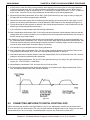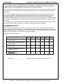
1
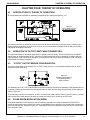
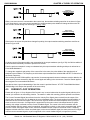
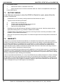
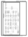
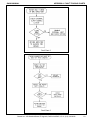
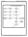
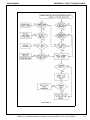
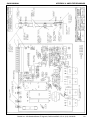
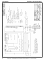
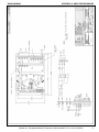
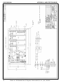
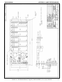
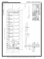
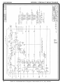
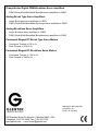
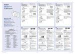
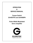
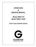
OPERATION
&
SERVICE MANUAL
Model GA369
Pulse Width Modulated
Servo Amplifier
GA369 MANUAL
TABLE OF CONTENTS
TABLE OF CONTENTS
CHAPTER ONE: INTRODUCTION
1.1 INTRODUCTION TO THE GA369 MANUAL ....................................................... 5
CHAPTER TWO: DESCRIPTION AND SPECIFICATIONS
2.1 DESCRIPTION OF THE GA369 ......................................................................... 6
2.2 AVAILABLE OPTIONS AND MODEL NUMBERING........................................... 6
2.2.1
2.2.2
2.2.3
2.2.4
2.2.5
2.2.6
2.2.7
2.3
2.3.1
2.3.2
2.3.3
SIGNAL INPUT .................................................................................................
VELOCITY MODE OR CURRENT MODE OPTIONS ........................................
+ AND - LIMITS .................................................................................................
TOTAL INHIBIT ................................................................................................
CARRIER FREQUENCY ..................................................................................
MULTI-AXES CONFIGURATIONS ...................................................................
EXAMPLE - MODEL NUMBERING ....................................................................
PROTECTION CIRCUITS.................................................................................
DRIVE INHIBIT INDICATOR OPERATION (RED LED) .....................................
LOW SPEED ELECTRONIC CIRCUIT BREAKER (RED LED) ..........................
HIGH SPEED ELECTRONIC CIRCUIT BREAKER (RED LED) .........................
6
6
6
6
6
6
7
7
7
7
7
2.4 SPECIFICATIONS.............................................................................................. 7
2.4.1
2.4.2
2.4.3
2.4.4
2.4.5
2.4.6
OUTPUT POWER ............................................................................................
INPUT POWER ................................................................................................
SIGNAL INPUTS ..............................................................................................
OTHER INPUTS AND OUTPUTS .....................................................................
MECHANICAL (ALSO SEE APPENDIXES B4-B7 AND Bi0-B13) ......................
TYPICAL FACTORY SETTINGS ......................................................................
7
7
8
8
8
8
CHAPTER THREE: PERSONALITY PREAMP CARD
3.1 INTRODUCTION TO THE PERSONALITY PREAMP CARD (GA369-3) ............ 9
3.1.1
3.1.2
VELOCITY MODE PERSONALITY PREAMP CARD ........................................ 9
CURRENT MODE PERSONALITY PREAMP CARD......................................... 9
3.2 DESCRIPTION OF OPTIONS AND ADJUSTMENTS......................................... 9
3.2.1
3.2.2
POTENTIOMETER ADJUSTMENTS ................................................................ 9
INPUT AND OUTPUT SIGNALS...................................................................... 10
3.3 REMOVAL AND INSTALLATION ..................................................................... 10
3.4 TROUBLE SHOOTING WITH THE PERSONALITY PREAMP CARD .............. 10
CHAPTER FOUR: THEORY OF OPERATION
4.1
4.2
4.3
4.4
4.5
4.6
INTRODUCTION TO THEORY OF OPERATION .............................................
OPERATION OF OUTPUT SWITCHING TRANSISTORS................................
“H TYPE” OUTPUT BRIDGE CONFIGURATION .............................................
PULSE WIDTH MODULATION (PWM) ............................................................
CURRENT LOOP OPERATION .......................................................................
VELOCITY LOOP OPERATION .......................................................................
11
11
11
11
12
13
CHAPTER FIVE: INSTALLATION PROCEDURE
5.1 MOUNTING ...................................................................................................... 14
5.2 WIRING SIZE AND PROPER TECHNIQUE ..................................................... 14
5.3 BASEPLATE CONNECTIONS ......................................................................... 14
5.3.1
INPUT FROM SECONDARY OF POWER TRANSFORMER ........................... 14
5.4 AMPLIFIER MODULE CONNECTIONS AND FUNCTIONS ............................. 14
5.4.1
5.4.2
5.4.3
5.4.4
5.4.5
D.C. BUSS ...................................................................................................... 14
MOTOR........................................................................................................... 15
SIGNAL INPUT ................................................................................................ 15
TACHOMETER INPUT .................................................................................... 15
CURRENT SENSE .......................................................................................... 15
Glentek Inc. 208 Standard Street, El Segundo, California 90245, U.S.A. (310) 322-3026
3
GA369 MANUAL
5.4.6
5.4.7
5.4.8
5.4.9
TABLE OF CONTENTS
+ AND - LIMITS...............................................................................................
TOTAL INHIBIT ...............................................................................................
FAULT MONITOR ...........................................................................................
RESET ............................................................................................................
15
15
15
15
CHAPTER SIX: START UP AND ADJUSTMENT PROCEDURE
6.1
6.2
6.3
6.4
6.5
SAFETY PRECAUTIONS .................................................................................
AMPLIFIER ALIGNMENT INTRODUCTION .....................................................
VELOCITY LOOP PHASING ............................................................................
TACH GAIN ADJUSTMENT..............................................................................
CONNECTING AMPLIFIER TO DIGITAL POSITION LOOP .............................
16
16
16
16
17
CHAPTER SEVEN: MAINTENANCE, REPAIR AND WARRANTY
7.1 MAINTENANCE INTRODUCTION .................................................................... 19
7.2 REPAIR ............................................................................................................ 19
7.2.1
7.2.2
7.2.3
7.2.4
7.2.5
FAULT TRACING ............................................................................................
FAULT TRACING CHARTS .............................................................................
PART REPLACEMENT ...................................................................................
LOW SPEED ELECTRONIC CIRCUIT BREAKER (LS/ECB) SHUTDOWN ......
HIGH SPEED ELECTRONIC CIRCUIT BREAKER (HS/ECB) SHUTDOWN.....
19
19
19
19
19
7.3 FACTORY REPAIR .......................................................................................... 20
7.4 WARRANTY ..................................................................................................... 20
APPENDIX A: FAULT TRACING CHARTS
FAULT CHART 1
FAULT CHART 2
FAULT CHART 3
FAULT CHART 4
Motor does not turn in either direction ........................................
Motor only turns in one direction ................................................
Motor wanders and hunts or does not track smoothly ................
Motor does not develop maximum output speed
(no load applied) in either direction ............................................
FAULT CHART 5 Motor does not develop max output torque in either direction ....
ENGINEERING NOTES FOR FAULT TRACING CHARTS .......................................
22
23
23
24
25
26
APPENDIX B: AMPLIFIER DRAWINGS
INSTALLATION SCHEMATIC (GA369) (369-1007)..................................................
ASSEMBLY CONTROL BOARD (GA369-1) (369-1002)...........................................
INSTALLATION DIAGRAM (GA369-1) (369-1008) ...................................................
INSTALLATION DIAGRAM (GA369-2A-2) (369-1205) .............................................
INSTALLATION DIAGRAM (GA369-4A-4) (369-1207) .............................................
INSTALLATION DIAGRAM (GA369-6A-6) (369-1211) .............................................
INSTALLATION DIAGRAM (GA369-8A-8) (369-1209) .............................................
-
-
-
-
-
28
29
30
31
32
33
34
APPENDIX C: PERSONALITY PREAMP
SCHEMATIC PERSONALITY PREAMP (369-1200) ................................................. 36
ASSEMBLY PERSONALITY PREAMP (369-1202) ................................................... 37
4
Glentek Inc. 208 Standard Street, El Segundo, California 90245, U.S.A. (310) 322-3026
GA369 MANUAL
CHAPTER ONE: INTRODUCTION
INTRODUCTION
1.1
INTRODUCTION TO THE GA369 MANUAL:
This manual is intended for use with Glentek’s TORQUE-SWlTCHTM series, model GA369 Pulse-Width-Modulated
(PWM) servo amplifiers. It provides all of the information that is required for installation, alignment and maintenance
of the GA369. We suggest that you take the time to read this manual from cover to cover before trying to work with a
GA369 amplifier. If you have any questions that you can not find the answer to in this manual please feel free to call
and discuss your problem or question with a Glentek applications engineer. Having been in the servo system business for over 26 years, we have a vast pool of applications knowledge waiting to help you.
Thank you for using Glentek’s products. It is our goal to save you money, time and provide you with a superior product.
Glentek Inc. 208 Standard Street, El Segundo, California 90245, U.S.A. (310) 322-3026
5
GA369 MANUAL
CHAPTER 2: DESCRIPTION, FEATURES AND SPECIFICATIONS
CHAPTER TWO: DESCRIPTION, AND SPECIFICATIONS
2.1
DESCRIPTION OF THE GA369:
The GA369 are modular, high power, high bandwidth PWM servo amplifiers designed for use with DC permanent
magnet servomotors. The GA369 utilize todays latest technology in power semiconductors for high efficiency which in
turn makes the amplifiers extremely reliable in today’s and tomorrow’s demanding applications.
2.2
DESCRIPTION OF AVAILABLE OPTIONS AND MODEL NUMBERING
INFORMATION:
2.2.1
SIGNAL INPUT:
The GA369 is available with two signal inputs, one single-ended and one differential. The differential input is
marked Aux. and Aux. Ret. and may be connected single ended by grounding Aux. Ret. (Refer to Appendix C,
drawings 369-1200 and 369-1202).
2.2.2
VELOCITY MODE OR CURRENT MODE OPTIONS:
The GA369 are most often used to close a critically damped velocity loop using a DC tachometer for velocity
feedback. However, this high gain input summing amplifier can be bypassed providing an input directly to the
current loop amplifier. The part number designator for this Current Mode option is CM and follows next in the
sequence of part number (Ex. :GA369CM). If the CM is absent from the part number, the amplifier will be
configured for Velocity Mode (Refer to Appendix C, drawings 369-1200 or 369-1202).
2.2.3
+ AND - LIMITS:
The GA369 may be configured for three different end of travel limit circuits with pull-up resistors (4.7k) to either
+ 5VDC or +1 5VDC. (Refer to Appendix C, drawing 369-1200)
Type A: Requires grounding of pin 8 or pin 9 to disable amplifier. To implement type A limits refer to appendix
B, drawing 369-1200.
Type B: Requires a positive voltage at pin 8 or pin 9 to disable amplifier. To implement type B limits refer to
Appendix B, drawing 369-1200.
Type C: Requires the removal of a ground from pin 8 or pin 9 to disable amplifier. To implement type C limits
refer to Appendix B, drawing 369-1200.
The amplifier is normally shipped with the type A + and - limit configuration with +1 5V pull-up resistors.
Designation letter A, B or C is added next to the part number to indicate type of limit circuit desired (Ex. :
GA369CMA-1, would have type A limits).
2.2.4
TOTAL INHIBIT:
The GA369 may be configured for three different Total Inhibit circuits (See 2.2.3 + AND - LIMITS above and
refer to drawing 369-1200). The amplifier is normally shipped with type A Total Inhibit.
2.2.5
CARRIER FREQUENCY:
The GA369 is provided with a carrier frequency of 10 KHz. Other carrier frequencies are available consult
Glentek.
2.2.6
MULTI-AXES CONFIGURATIONS:
The single and multi-axes part number designators are as follows:
GA369-1
GA369-2A-1
GA369-2A-2
GA369-4A-3
GA369-4A-4
GA369-6A-5
GA369-6A-6
6
Single amplifier module.
2 Axes chassis with 1 Amplifier module.
2 Axes chassis with 2 Amplifier modules.
4 Axes chassis with 3 Amplifier modules.
4 Axes chassis with 4 Amplifier modules.
6 Axes chassis with 5 Amplifier modules.
6 Axes chassis with 6 Amplifier modules.
Glentek Inc. 208 Standard Street, El Segundo, California 90245, U.S.A. (310) 322-3026
GA369 MANUAL
2.2.7
CHAPTER 2: DESCRIPTION, FEATURES AND SPECIFICATIONS
EXAMPLE MODEL NUMBERING:
-
The following example of GA369 part numbering, is provided to help you better understand Glentek’s part
numbering system:
Example: GA369CMA-4A-3
In this example, the GA369 part number describes the following amplifier configuration:
CM = Current Mode input option A Type A + and - Limit option.
-4A = 4 Axes chassis
-3 = 3 Amplifier modules installed.
For this example each of the three amplifier modules would be labeled GA369-1 or GA369-1 with serial
number and CMA designator at bottom of label. The 4 axes chassis would be labeled GA369-4A-3 with serial
number and CMA designator at bottom of label.
2.3
PROTECTION CIRCUITS:
The following protection circuits are integral to the GA369 amplifiers to prevent damage to the amplifier and your
equipment. Again, Glentek is anxious to work with you in helping to implement any circuit functions your system might
require.
Note:
For 2.3.1 to 2.3.3 refer to Appendix B, drawing 369-1007.
2.3.1
DRIVE INHIBIT INDICATOR OPERATION (RED LED):
The LED 1 Drive Inhibit indicator light will turn ON and latch for the two following conditions:
1.
Low Speed Electronic Circuit Breaker (LS/ECB) triggered.
2.
High Speed Electronic Circuit Breaker (HS/ECB) triggered.
2.3.2
LOW SPEED ELECTRONIC CIRCUIT BREAKER:
This circuit protects the motor, amplifier and mechanical system from damage due to excessive mechanical
bind in the system or possibly driving into a hard mechanical stop. Circuit operation is as follows:
When the motor current exceeds the value set at TP1, typically 3.0 VDC (scale factor 1 VOLT=2 AMPS), IQ3-1
switches positive and voltage on C5 begins integrating up. If the current remains above the set point, typically
0.5 seconds, Q9 will trigger the ECB latch and the Drive Inhibited indicator.
2.3.3
HIGH SPEED ELECTRONIC CIRCUIT BREAKER:
This circuit protects the amplifier from dead shorts across the amplifier output terminals. The HS/ECB is always
factory set and should not be adjusted. The typical factory setting is 29 Amps for 10 micro seconds. Again, this
circuit triggers the ECB latch and the Drive Inhibited indicator.
2.4
SPECIFICATIONS:
The specifications for each GA369 amplifier module is as follows:
2.4.1
OUTPUT POWER
OUTPUT CURRENT (PEAK):
±12 AMPS
OUTPUT CURRENT (RMS):
±6 AMPS
DC BUSS VOLTAGE:
+35VDCTO +7OVDC
(Higher and lower Buss Voltages available, consult Glentek.)
Note:
DC Buss voltage should be selected approximately 10%-20% above the maximum voltage required
at motor terminals for maximum system efficiency.
2.4.2
INPUT POWER:
INPUT POWER FOR DC BUSS: A fused single or three phase full wave rectifier and filter capacitor are
provided on the base plate. The AC input to this circuit is supplied by a separately mounted power transformer
unique to the application. The power transformer and motor output inductors are not standard parts of the
amplifier package. Glentek has power transformers and inductors in stock for your system requirements.
Glentek Inc. 208 Standard Street, El Segundo, California 90245, U.S.A. (310) 322-3026
7
GA369 MANUAL
2.4.3
CHAPTER 2: DESCRIPTION, FEATURES AND SPECIFICATIONS
SIGNAL INPUTS:
VOLTAGE,MAXIMUM
Aux. Input
Sig. Input
Tach. Input
Input Impedance, Minimum
±13 Volts
±70 Volts
±90 Volts
10K Ohm
GAIN,MAXIMUM
Sig. and Aux. Inputs
Tachometer
Drift (Ref. to Input), Maximum
Frequency Response, Minimum
Dead Band
Form Factor
15,000 Amps/Volt
7,000 Amps/Volt
0.01 mV/°C
750 Hz
None
1.01
2.4.4 OTHER INPUTS AND OUTPUTS
+and - Limits (Type “A’1)
Total Inhibit (Type “A”)
Gnd. to reset
Fault Monitor
Activated by a 3ma. contact closure to common.
Activated by a 3ma. contact closure to common.
Activated by a 3ma. contact closure to common.
4.7k ohm pull-up to +5VDC or + 15VDC ,will sink 50 ma.
2.4.5 MECHANICAL (SEE APPENDIXES B4-B7)
Mounting
Height
Cooling
Any Position
7 inches
50°C Ambient Max.
Baseplate
GA369-2A-2
GA369-4A-4
GA369-6A-6
6.25 in. x 8.8 in.
6.25 in. x 12.2 in.
6.25 in. x 19.0 in.
Weight
GA369-1
GA369-2A-2
GA369-4A-4
GA369-6A-6
1.14 lbs.
5.1 lbs.
7.5 lbs.
9.5 lbs.
2.4.6 TYPICAL FACTORY SETTINGS
Sig. and Aux. Gain
Tach. Gain
Loop Gain
Comp.
LS/ECB
HS/ECB
8
5V(Sig.)/7V(Tach.)
50%
CCW (OFF)
CW (Mm. Bandwidth)
6A @ 0.5 sec.
29A ~ 10 micro sec.
Glentek Inc. 208 Standard Street, El Segundo, California 90245, U.S.A. (310) 322-3026
GA369 MANUAL
CHAPTER 3: PERSONALITY PREAMP CARD
CHAPTER THREE: PERSONALITY PREAMP CARD
3.1
INTRODUCTION TO THE PERSONALITY PREAMP CARD (GA369-3):
The Personality Preamp card is a modular plug-in card that comes in two versions: velocity mode and current mode.
Schematic and Board Assembly prints for this card are found in Appendix C, drawing numbers 369-1200, 369-1202
and will be referred to in the following description.
The Personality card contains the main high gain preamp with all associated system alignment adjustments. This
card greatly enhances system troubleshooting and repair; in that if an amplifier should fail, simply remove the
Personality card (which has all of the original system constants adjusted in) and replace it on a spare amplifier. This
eliminates system realignment when changing out amplifiers. Also, a motor-tach-load may be aligned at the factory
and then just the Personality card sent to the field for system test.
3.1.1
VELOCITY MODE PERSONALITY PREAMP CARD:
The Velocity Mode Preamp Card contains the main high gain preamp with all the associated system alignment
adjustments to close a velocity loop using a D.C. tachometer for velocity feedback. (Refer to Appendix C,
drawings 369-1200 and 369-1202)
3.1.2
CURRENT MODE PERSONALITY PREAMP CARD:
The Current Mode Personality Card contains all the system alignment adjustments to control a current mode
amplifier. (Refer to Appendix C, drawings 369-1200 and 369-1202)
3.2
DESCRIPTION OF OPTIONS AND ADJUSTMENTS:
The Personality Preamp card is a small printed circuit card (3.3” x 4.3”) standing on two 12 pin connectors (0.45” tall)
that mate with appropriate sockets on the amplifier control board.
The Personality card is most often used to close a velocity loop using a DC tachometer for velocity feedback.
However, the high gain input summing amplifier can be bypassed providing an input directly to the current loop
amplifier (Current Mode option). If the Current Mode (CM) option is specified the Velocity Mode Personality Preamp
Card is converted to a Current Mode Personality Preamp Card. (Refer to Appendix C, drawings 369-1200 and 3691202)
3.2.1
POTENTIOMETER ADJUSTMENTS:
The following is a description of the potentiometer adjustments used for the two modes of operation. Please
refer to Chapter Six on Start Up and Adjustment Procedures for a detailed description of how to set these
potentiometers.
VELOCITY MODE: (Refer to Appendix C, drawings 369-1200 and 369-1202)
R15 Signal Gain potentiometer sets the input voltage to output RPM required by your system for the singleended input. (Ex.: 10 VOLTS INPUT = 2000 RPM)
R45 Auxiliary Signal Gain potentiometer sets the input voltage to output RPM required by your system for the
differential signal input (Ex.: 10 VOLTS INPUT = 2000 RPM).
R21 Tachometer Gain potentiometer sets the amount of tach signal required by your system. Use in
conjunction with the Compensation potentiometer, R16, to adjust the system bandwidth.
R43 Balance potentiometer used to null out any DC offset in the amplifier (Ex.: 0 VDC INPUT = 0 RPM).
R55 Compensation potentiometer sets the amount of bandwidth (frequency response) required by your
system. Use in conjunction with the Tachometer Gain potentiometer, R14, to adjust the system bandwidth.
R57 Current Limit potentiometer sets the maximum acceleration and deceleration current.
R59 Loop Gain potentiometer used to reduce the velocity loop gain to zero when the system is first turned on
to prevent run away operation. Before turning the system on for the first time this potentiometer is set fully
CCW to command zero current to the motor. Once the system is correctly phased this potentiometer is set fully
CW for all further system adjustments.
CURRENT MODE: (Refer to Appendix C, drawings 369-1200 and 369-1202)
Glentek Inc. 208 Standard Street, El Segundo, California 90245, U.S.A. (310) 322-3026
9
GA369 MANUAL
CHAPTER 3: PERSONALITY PREAMP CARD
R15 Signal Gain potentiometer sets the input voltage to output current required by your system for the singleended input. (Ex.: 5 VOLTS INPUT = 2 AMPS OUTPUT CURRENT)
R45 Auxiliary Signal Gain potentiometer sets the input voltage to output RPM required by your system for the
differential signal input (Ex.: 5 VOLTS INPUT = 2 AMPS OUTPUT CURRENT).
R57 Current Limit potentiometer sets the maximum acceleration and deceleration current.
R59 Loop Gain potentiometer is factory set to prevent amplifier maximum rated current from being exceeded
when the current limit potentiometer is fully CW.
R43 Balance potentiometer used to null out any DC offset in the amplifier. (Ex.: 0 VDC INPUT = 0 CURRENT
OUTPUT)
3.2.2
INPUT AND OUTPUT SIGNALS:
Connector P2 Pin No. (Signals to and from connector J1)
1
AUXILIARY
Differential signal input.
2
AUXILIARY RETURN
Differential signal input.
3
SIGNAL
Single-ended signal input.
4
SIGNAL COMMON
Signal common.
5
TACHOMETER
Tachometer signal input.
6
TACHOMETER COMMON
Signal common.
7
RESET
Resets amplifier after a fault (input).
8
+ LIMIT
Inhibits motor rotation in the + direction (input).
9
-LIMIT
Inhibits motor rotation in the - direction (input).
10
TOTAL INHIBIT
Inhibits motor rotation in the both directions (input).
11
COMMON
Signal common and ± 15 VDC common.
12
FAULT
Fault monitor output.
Connector P3 Pin No. (Signals to and from power board)
1
INHIBIT
Total inhibit output.
2
CURRENT SIGNAL
Velocity error or current command output.
3
CURRENT SENSE
Current sense input.
4
+ LIMIT
+ Limit output.
5
-LIMIT
- Limit output.
6
+15VDC
+ 15VDC power.
7
COMMON
± 15 VDC and signal common.
8
COMMON
± 15 VDC and signal common.
9
COMMON
± 15 VDC and signal common.
10
-15 VDC
- 15 VDC power.
11
FAULT
Fault input.
12
RESET
Reset output.
3.3
REMOVAL AND INSTALLATION:
When removing or installing the Personality Preamp card, care must be taken not to damage any of the
components under the card on the amplifier controller board or on the Personality card.
Removal:
Remove the retaining screw hold the Personality card by its edges and pull straight away from the
amplifier controller board (Do not pull on the components). For amplifiers with Personality card mounted vertically,
remove amplifier module first before unplugging Personality card.
Installation:
Hold the Personality card by it’s edges and carefully align the two 12 pin connectors with their mating
sockets and push straight toward the amplifier controller board until it is firmly seated (Do not press on any of the
components) and replace the retaining screw.
3.4
TROUBLE SHOOTING WITH THE PERSONALITY CARD:
If your system exhibits a problem and a working amplifier module is available fault tracing can be expedited by
removing the Personality Preamp card from the malfunctioning amplifier, plugging it into the replacement amplifier
and testing the system. If the system does not work with the new amplifier module, Refer to Chapter Seven on
Maintenance and Repair for a more detailed fault tracing procedure. However, if the system does work with the new
amplifier module, check the malfunctioning unit for loose connections and retest the suspected unit in the system.
10
Glentek Inc. 208 Standard Street, El Segundo, California 90245, U.S.A. (310) 322-3026
GA369 MANUAL
CHAPTER 4: THEORY OF OPERATION
CHAPTER FOUR: THEORY OF OPERATION
4.1
INTRODUCTION TO THEORY OF OPERATION:
A Velocity Mode servo amplifier is essentially comprised of two control loops (see fig. 4.1).
Figure 4.1
Velocity mode sevo loop
for a brush type motor
The inside control loop is referred to as the Current Loop and the outside loop is referred to as the Velocity Loop.
Before we begin our analysis of the Current Loop, let us review some basic concepts which will help you to better
understand the amplifier’s operation.
4.2
OPERATION OF OUTPUT SWITCHING TRANSISTORS:
The output transistors, for all intents and purposes, operate in only two states. They are analogous to an ON/OFF
switch. When an output transistor is OFF, there is no current flowing through it (it’s resistance is infinite). When an
output transistor is ON, current flows through it (it’s resistance is near zero). When the transistor is ON, it is technically referred to as being in saturation.
4.3
“H TYPE” OUTPUT BRIDGE CONFIGURATION:
The output configuration of the amplifier is a “H TYPE” bridge (see fig. 4.2 for schematic representation of output
bridge with motor connected).
Figure 4.2
Schematic representation of
an output bridge with a
motor connected.
The advantage of an “H TYPE” output bridge configuration is that by controlling the switching of the opposite pairs of
transistors, current can be made to flow through the motor in either direction using a single polarity power supply as
shown in figure 4.2.
To provide motor current in one direction, A and C are turned ON, while B and D remain in the OFF state. To provide
motor current in the other direction, B and 0 are turned ON, while A and C remain in the OFF state.
4.4
PULSE-WIDTH-MODULATION (PWM):
Pulse-Width-Modulation is the technique used for switching opposite pairs of output transistors ON and OFF to
control the motor drive current. When zero current is commanded to the current loop, the opposite pair of transistors
are turned ON and OFF as shown in figure 4.3. Note that since the pulse widths are equal, the net DC current in the
motor is equal to zero.
Glentek Inc. 208 Standard Street, El Segundo, California 90245, U.S.A. (310) 322-3026
11
GA369 MANUAL
CHAPTER 4: THEORY OF OPERATION
Figure 4.3
Transistor switching
waveform at zero
current
When a non-zero current is commanded to the current loop, the transistor switching waveform is as shown in figure
4.4A. Since there is a non-zero current command, the output transistor pulse widths will change and the motor will
see a net DC current flowing from A through C (see fig. 4.3A).
Figure 4.3A
Transistor switching
waveform when current
flows from A through C
If the input to the current loop had been changed in polarity, the output transistor switching waveform would be as
shown in figure 4.3B.
Figure 4.3B
Transistor switching
waveform when current
flows from B through D
If a larger current of the same polarity was commanded to the output transistors (see fig. 4.3B), the ON time widths of
B and 0 would automatically increase to provide more current.
From the previous examples it is easy to understand why this output transistor switching technique is referred to as
Pulse-Width-Modulation.
To change the magnitude and polarity of the current flow in the motor, the pulse widths of the opposite pairs of
transistors are modulated. The frequency at which these output transistors are switched ON and OFF is referred to as
the Carrier Frequency.
After realizing how the PWM amplifier output works, it becomes apparent that some inductance must be added to the
motor circuit to prevent excessively high AC current ripple and heating in the servomotor. Consult a Glentek applications engineer for recommended inductance.
Now that we have a good understanding of how the current is provided from an “H TYPE” Pulse-Width-Modulated
(PWM) bridge, let’s analyze the operation of the current loop.
4.5
CURRENT LOOP OPERATION:
Please refer to figure 4.1 for a diagram of the Current Loop. In control electronics the symbol sigma (with the circle
around it) is referred to as a Summing Junction. The manner in which this summing junction operates is as follows:
The Current Command Signal (also referred to as the Velocity Error Signal when received from the output of the
velocity loop, as shown in fig. 4.1) is added to the current feedback signal. The signal resulting from this addition, is
referred to as the Current Error Signal. This current error signal is fed into the current amplifier, which in turn produces a current in the motor. A voltage which is proportional to the motor current is developed across Rs (shunt
resistor), this voltage is referred to as the Current Feedback Signal. The current in the motor increases until the
current feedback signal is exactly equal in magnitude, but opposite in polarity, to the current command signal. At this
point the current error signal drops to zero, and the commanded current is equal to the actual current. If anything
happens to disturb either the current command signal, or the current feedback signal, the same process occurs again
until the current command signal is equal in magnitude to the current feedback signal, but opposite in polarity.
12
Glentek Inc. 208 Standard Street, El Segundo, California 90245, U.S.A. (310) 322-3026
GA369 MANUAL
CHAPTER 4: THEORY OF OPERATION
The type of loop described above is referred to as a Servo Loop because the current servos about a commanded
value.
We are surrounded in our everyday lives by a multitude of servo loops. For example, many of today’s luxury cars
have what is called “automatic climate control”. To operate this servo loop you set the climate control to the temperature that you wish to be maintained in the interior of the car (current command signal). The selected temperature is
then summed with the actual temperature from a thermometer (current feedback), and the output (current error
signal) activates either the heater or the air-conditioner until the set temperature (current command signal) is equal in
magnitude, but opposite in polarity, to the actual temperature as measured by the thermometer (current feedback).
4.6
VELOCITY LOOP OPERATION:
Please refer to figure 4.1 for a diagram of a typical Velocity Loop. The velocity loop’s operational description is
analogous to the current loop description, except for the fact that the input signal is called the Velocity Command and
the feedback signal from the DC tachometer is called the Velocity Feedback.
Glentek Inc. 208 Standard Street, El Segundo, California 90245, U.S.A. (310) 322-3026
13
GA369 MANUAL
CHAPTER 5: INSTALLATION PROCEDURE
CHAPTER FIVE: INSTALLATION PROCEDURE
5.1
MOUNTING:
The installation diagrams in Appendix B show the bolthole mounting pattern to support the amplifier. The mounting
holes will accept a 1/4-inch bolt. The base material is cadmium plated .060 inch thick steel.
THE MOUNTING BOLT SHOULD PROVIDE AN ELECTRICAL GROUND FOR THE CHASSIS TO MINIMIZE
SHOCK HAZARD.
The surface that the amplifier package will be mounted on must be able to support its weight, but does not need to
provide “cold plate” cooling for the amplifier.
It is recommended to allow a minimum of one inch clearance from any side and the top of the amplifier to the cabinet
wall for air circulation, wire routing and terminal strip access.
The amplifier package should be mounted in a clean, dry enclosure with a maximum ambient temperature of 500C.
To ensure maximum reliability, keep the amplifier cabinet cool and free from dust, oil and other contaminates.
NEVER INSTALL THE AMPLIFIER PACKAGE IN ANY LOCATION WHERE FLAMMABLE OR EXPLOSIVE
VAPORS ARE PRESENT
5.2
WIRING SIZE AND PROPER TECHNIQUE:
Please refer to Appendix B, GA369 installation diagrams. These installation diagrams show the necessary external
connections to ensure proper amplifier operation.
Glentek recommends that your wiring be in accordance with all national and local codes that are applicable to your
system. Wire size must be sufficient to accommodate the maximum continuous current that will be run thru it.
Recommended wire sizes for the GA369 are as follows:
MOTOR ARMATURE -14 ga.
0-105 VAC POWER INPUT (from secondary of power transformer) - 14 ga.
120 VAC FOR FANS - 16 ga. twisted pair.
SIGNAL INPUT - 22 ga. mm. 2 conductor with shield.
TACHOMETER INPUT - 22 ga. mm. 2 conductor with shield. Terminate shield, one end only at tachometer
common TB1 terminal 6 of amplifier module.
When wiring to and from the drive cabinet, it is considered good technique to route the power lines (16 ga. and larger)
along different paths than the signal and tachometer lines. This minimizes the amount of stray noise and pick-up that
is injected into the amplifier.
5.3
BASEPLATE CONNECTIONS:
5.3.1
INPUT FROM SECONDARY OF POWER TRANSFORMER:
The AC voltage that is used to form the DC Buss of the amplifier package, is supplied from a
separately mounted transformer that has been selected by Glentek for your application. Connect the
secondary of the power transformer to terminals 2 and 3 of TB2O1 on systems with a single phase input, and
to terminals 1, 2 and 3 of TB2O1 on systems with a three phase input.
DO NOT APPLY ANY POWER YET.
5.4
AMPLIFIER CONNECTIONS AND FUNCTIONS:
5.4.1
DC BUSS:
The DC Buss, from the filter capacitor is connected to terminals 1 (+) and 2 (-) of terminal strip TB1. This
connection is already made for you on our multiaxes packages. The power transformer for the DC Buss is not
a standard part of the amplifier package. Glentek can advise on transformer specifications required. Most
styles and sizes are in stock at Glentek.
14
Glentek Inc. 208 Standard Street, El Segundo, California 90245, U.S.A. (310) 322-3026
GA369 MANUAL
5.4.2
CHAPTER 5: INSTALLATION PROCEDURE
MOTOR:
The Motor is connected to terminals 3(-) and 4(+) of terminal strip TB1 of the amplifier module (SEE
APPENDIXES B4-B7). In most cases, if the motor inductance is less than 1 millihenry, an inductor should be
connected in series with the motor leads. The inductor is considered to be a separate part from the amplifier
package. Glentek can advise on the inductor specifications, and most styles and sizes are in stock at Glentek.
IT IS IMPERATIVE THAT YOU DO NOT USE GROUNDED TEST EQUIPMENT ON
THE MOTOR ARMATURE NOR CONNECT EITHER END OF THE MOTOR
ARMATURE
TO SIGNAL GROUND OR DC BUSS RETURN.
5.4.3
SIGNAL INPUT:
The amplifier has two Signal Inputs, one single-ended (Signal Input J1-3) and one differential (Auxiliary Signal
Input J1-1, Auxiliary Return J1-2). Please refer to Chapter 2.2 for options and model numbering information.
Typically when operating in the velocity mode, the input signal range is ± 10 VDC. The input voltage is
summed with a precision DC tachometer to provide accurate velocity control at the servo motor shaft (see fig.
4.1).
The Signal Gain potentiometer (10 K ohm), R15, and Auxiliary Gain potentiometer, R45, adjust the
motor velocity desired for a given input voltage velocity command.
5.4.4
TACHOMETER INPUT:
The Tachometer is connected to terminals 5 and 6 of terminal strip J1 of the amplifier module (see 5.2 for
recommended wire type & size).
5.4.5
CURRENT SENSE:
The Current Sense output signal can be monitored at TP 7 on the preamp card (see appendix C, drawings
369-1200 and 369-1202). It is an isolated output signal that is proportional to motor current. The scale factor is
1 VOLT = 2 AMPS.
5.4.6
+ AND - LIMITS:
The + and - Limits are located respectively at terminals 8 and 9 of terminal strip J1 of the amplifier module.
Please refer to 2.2.3 for a description of the different configurations of limits that are available. Amplifier
modules are normally shipped with type “A” limits when terminals (J1-8 or J1-9) are pulled to ground (J1-11) by
some external circuit the amplifier is inhibited in the + or - direction.
5.4.7
TOTAL INHIBIT:
The Total Inhibit is located at terminal 10 of terminal strip J1 of the amplifier module. Please refer to 2.2.3 for a
description of the different configurations of Total Inhibit that are available. Amplifier modules are normally
shipped with type “A” Total Inhibit [when terminal (J1-10) is pulled to ground (J1-11) by some external circuit
the amplifier is totally inhibited].
5.4.8
FAULT MONITOR:
The Fault Monitor is located at terminal 12 of terminal strip J1 of the amplifier module. The amplifier will pull
this terminal to ground by turning ON 01 for the following fault conditions:
1.
Low Speed Electronic Circuit Breaker (LS/ECB) triggered.
2.
High Speed Electronic Circuit Breaker (HS/ECB) triggered.
NOTE: Please refer to Chapter 2.3 on Protection Circuits for a more detailed description of the possible
conditions that will cause the above faults to occur.
5.4.9
RESET:
The amplifier can be reset two ways, by grounding the RESET input (J1-7) with a 3ma. contact closure to
amplifier common (J1-11) for 1 ms. minimum, or by removing all power and waiting for the buss capacitors to
discharge and reapplying power. (Refer to appendix B, drawing 369-1007 or appendix C, drawing 369-1200)
Glentek Inc. 208 Standard Street, El Segundo, California 90245, U.S.A. (310) 322-3026
15
GA369 MANUAL
CHAPTER 6: START UP AND ADJUSTMENT PROCEDURE
CHAPTER SIX: START UP AND ADJUSTMENT PROCEDURE
6.1
SAFETY PRECAUTIONS:
Before starting the adjustment and alignment procedure please be sure to observe
the following precautions:
1. Be certain that there are no visibly loose or damaged components.
2. Check that all connections are tight.
3. Check all power and signal wiring. Remove power input fuses, apply power and measure that correct power
voltage is being applied. Your DC Buss voltage will be 1.4 x the AC power applied (Refer to Appendix A, note 1).
4. Be sure that the motor mechanism is clear of all obstructions. If motor is connected to an axis lead screw or other
device with limited motion, place at midposition.
5. Work on only one amplifier at a time.
6. Make sure all Loop Gain pots are turned fully CCW before applying power.
7. DO NOT use grounded test equipment.
6.2
AMPLIFIER ALIGNMENT INTRODUCTION:
When adjusting an amplifier for optimum velocity loop operation it is desirable to achieve a critically damped, stable
step velocity response with maximum DC Tach Gain. The following discussion will describe how to best achieve this
result:
Your amplifier has been run at the factory with a known motor, tachometer and inertial load. In testing at the factory
we try to simulate the same conditions you will have in your system. For this reason it is a good idea to start with the
initial settings as shipped from the factory.
NOTE:
All of the following adjustments are to be made on the Personality Preamp card (Refer to Appendix
C, drawings 369-1200 & 369-1202).
6.3
VELOCITY LOOP PHASING:
For proper servo operation it is necessary for the amplifier to receive negative feedback from the tachometer. If the
tachometer leads are reversed (positive feedback), the amplifier will run away. To check the phasing of the motor and
tachometer proceed as follows:
1. Make sure Loop Gain potentiometer, R59, is full CCW (as shipped from factory).
2. Make sure that nothing is connected to the Signal Input (J1-3) or the Auxiliary Signal Input (J1-1 or J1-2).
3. Apply the main power.
4. Slowly turn the Loop Gain potentiometer, R59, CW. If the motor starts to run away turn the Loop Gain potentiometer full CCW and reverse the motor armature leads. Again, turn the Loop Gain potentiometer CW. The motor
should be stopped or rotating slowly.
5. Leave Loop Gain potentiometer, R59, full CW for all remaining adjustments and operations.
6.4
TACH GAIN ADJUSTMENT:
1. At this point the motor will be rotating slowly. Adjust the Balance potentiometer,R43, until the motor rotation is
stopped.
2. While observing the tachometer output voltage with an oscilloscope, apply a step input voltage at the Signal Input
terminal of the amplifier. A step input voltage can be simulated by applying and removing a flashlight battery to
the Signal Input. For this purpose the battery is usually mounted inside of a small box with a switch. Common
names used to describe this DC signal voltage source are Battery Box or DC Simulator. Elaborate signal sources
are often made for this purpose including bipolar output, potentiometer output adjust and polarity reversing
switches, etc. You often hear the term “DC Box the velocity loop servo” being used by people working on servo
systems.
(This Signal Box may be purchased from Glentek Inc., Part Number BB700)
16
Glentek Inc. 208 Standard Street, El Segundo, California 90245, U.S.A. (310) 322-3026
GA369 MANUAL
CHAPTER 6: START UP AND ADJUSTMENT PROCEDURE
3. At this point the motor should be running smoothly. While applying and removing the DC input signal adjust the
Current Limit potentiometer, R57, for desired maximum acceleration and deceleration current. Motor current
should be observed by using an oscilloscope at TP-7. Scale factor of voltage at this point is 1 VOLT = 2 AMPS of
motor current. Leave the Current Limit potentiometer at this setting for all remaining adjustments.
4. Adjust the Signal Gain potentiometer, R15 or R45, of the signal input that you are using so when you apply the
DC signal the motor rotates at approximately 400 RPM.
5. Observe the tachometer voltage with an oscilloscope while applying and removing the DC input signal. You will
observe one of three possible waveforms; Critically Damped, Under Damped or Over Damped (see figure 6.4).
6. The waveform that for many systems is optimum is the critically damped waveform. If the waveform that you are
observing is critically damped proceed to step 9.
7. If your waveform is under damped make the following adjustments:
Turn the Compensation potentiometer, R55, CCW until the waveform becomes critically damped. Note here that the
limiting factor will be a motor oscillation, you must always leave the Compensation potentiometer CW enough so
that the velocity loop remains stable.
If the waveform is still under damped after adjusting the Compensation potentiometer for maximum bandwidth, turn
the Tachometer Gain potentiometer, R21, 2 turns CCW and then again adjust Compensation potentiometer, R55,
CCW until waveform becomes critically damped. Repeat procedure if necessary. Again, the servo velocity loop
must at all times remain stable. Consult the factory if necessary.
8. If the waveform is over damped make the following adjustments:
Turn the Tachometer Gain potentiometer, R21, CW until a slight overshoot appears on the waveform then turn the
Compensation potentiometer, R55, CCW until a critically damped waveform is observed.
9. Now that the waveform is critically damped, leave the Compensation, R55, and Tachometer Gain, R21, at these
settings for all remaining adjustments and operations.
10. Next set the Signal potentiometer, R15 or R45, of the signal input that you are using to the gain required by your
system (Ex.: 10 VOLTS INPUT = 2000 RPM).
11. Adjust Balance potentiometer, R43, one more time to null out any offset.
12. For all remaining adjustments when placing the amplifier in your system only the Signal potentiometer, R15 or
R45, and Balance potentiometer, R43, should be adjusted.
Figure 6.4
6.5
CONNECTING AMPLIFIER TO DIGITAL POSITION LOOP:
Before connecting the amplifier to the Digital Position Loop, be sure adjustments of section 6.4 have been made.
Start out with Loop Gain potentiometer, R18, fully CCW and activate the Digital Position Loop. Slowly turn loop Gain
potentiometer CW. If servo runs away, immediately adjust Loop Gain fully CCW and turn power OFF.
Glentek Inc. 208 Standard Street, El Segundo, California 90245, U.S.A. (310) 322-3026
17
GA369 MANUAL
CHAPTER 6: START UP AND ADJUSTMENT PROCEDURE
1. It is possible, at this time, that the Digital Loop is reverse phased. An example of this would be if a positive
voltage from the velocity DAC required the motor to turn CW, however, it turned CCW instead causing the encoder
feedback signal to count up instead of down. This would cause a run away condition.
If you are out of phase as described, be sure power is OFF and reverse the motor leads at the amplifier and also the
tachometer leads. This will cause the motor to rotate in the opposite direction as it did before, properly phasing the
Digital Loop.
2. Now with the Digital Loop operating, turn the Loop Gain potentiometer, R1B, fully CW and command a small
move. Slowly increase or decrease the Signal Gain potentiometer, R12 or R13, of the amplifier until the servo is
operating as required. It should be noted here that too much Signal Gain at this point could cause instability
(oscillation). Do not stay in this oscillating condition long as it may result in system mechanical or electrical damage.
Be sure when all signal adjustments are made that the balance is rechecked and adjusted for zero rotation for zero
signal input.
3. It should be noted here that the GA369 are designed to operate with many different systems and if after reading
this manual you have further questions, do not hesitate to call a Glentek applications engineer.
ENGINEERING NOTE:
After all systems are aligned and functioning it is good practice to remove power from the amplifier and, using a
digital ohm-meter, measure the impedance value of the following potentiometer wiper settings with respect to signal
ground. These values may be useful for the next machine you align or for maintenance of this system at a later date.
Make these measurements on each amplifier on a multiaxis baseplate.
Record resistance measurements:
AMP 1
AMP 2
AMP 3
AMP 4
AMP 5
AMP 6
Signal voltage
Tachometer voltage
———
———
———
———
———
———
Date Taken:
Note any changes to compensation components, etc.:
Tach. potentiometer wiper to signal
ground. (ohms):
Signal potentiometer wiper to signal
ground. (ohms):
Comp. potentiometer wiper to signalground. (ohms):
Current limit potentiometer wiper to
signal ground (ohms):
18
____ ____ ____
Glentek Inc. 208 Standard Street, El Segundo, California 90245, U.S.A. (310) 322-3026
GA369 MANUAL
CHAPTER 7: MAINTENANCE, REPAIR AND WARRANTY
CHAPTER SEVEN: MAINTENANCE, REPAIR AND WARRANTY
7.1
MAINTENANCE:
The GA369 amplifiers do not require any scheduled maintenance.
7.2
REPAIR:
If your system exhibits a problem, this manual should assist you to identify the fault and to replace the defective
component or sub-assembly. The GA369 amplifiers are modular assemblies and each individual amplifier section is
designed to be easily removed and replaced at the field level. It is Glentek’s recommendation that a failed amplifier
module be replaced in the field and returned to Glentek for failure analysis and repair. However, Appendixes B and C
contain complete system schematics that, in case of extreme emergency, should permit a skilled electronic technician
to trouble shoot the circuit boards to levels lower than those recommended as replaceable.
7.2.1 FAULT TRACING:
This section will aid in the location of defective replaceable components and assemblies. A list of the fault
tracing charts in Appendix A, along with the observable fault follows:
Fault Chart 1
Motor does not turn in either direction.
Fault Chart 2
Motor only turns in one direction.
Fault Chart 3
Motor wanders and hunts or does not track smoothly.
Fault Chart 4
Motor does not develop maximum output speed (no load applied) in either direction.
Fault Chart 5
Motor does not develop maximum output torque in either direction.
7.2.2
FAULT TRACING CHARTS:
The fault tracing charts in Appendix A start with an observable fault listed at the top of each chart. Follow the
line connections between blocks by your answers to the questions noted in the diamond shape blocks until the
defective part is isolated. The charts are to be used only as a guide to identify the parts or assemblies that
Glentek recommends as the lowest level of repair.
The fault tracing procedures assume that only a single failure mode exists.
7.2.3
PART REPLACEMENT:
The removal and replacement of the defective assembly can be accomplished with standard shop procedures.
The assemblies that may be easily removed are as follows:
1.
Fuses F201-F202 on baseplate and Fl on each amplifier module.
2.
Rectifier BR2O1 and BR202.
3.
Capacitor C201, C202.
4.
Amplifier Module A1-A8.
After reviewing the fault tracing charts you may conclude that the complete amplifier should be returned to
Glentek for failure analysis, repair and retesting to specifications. This is particularly true with failure modes in
the amplifier module sections Al thru A8.
7.2.4
LOW SPEED ELECTRONIC CIRCUIT BREAKER (LS/ECB) SHUTDOWN:
The LS/ECB is tripped when a preset current threshold is exceeded for a preset length of time, typically 6
Amps for 0.5 seconds.
List of possible causes:
1.
Binding or stalling of motor shaft.
2.
Overload of amplifier output to motor.
3.
Large reflected load inertia.
The time delay is typically set at factory to your system requirements.
RESET:
The amplifier can be reset two ways, by grounding the RESET input (J1-7) with a 3ma.
contact closure to amplifier common (J1-11) for 1ms. minimum, or by removing all power and waiting for the
buss capacitors to discharge and reapplying power. (Refer to appendix B, drawings 369-1007 or 369-1200)
7.2.5
HIGH SPEED ELECTRONIC CIRCUIT BREAKER (HS/ECB) SHUTDOWN:
The HS/ECB is tripped by 29 or more Amps of output current for 10 micro seconds.
Glentek Inc. 208 Standard Street, El Segundo, California 90245, U.S.A. (310) 322-3026
19
GA369 MANUAL
CHAPTER 6: START UP and CALIBRATION
List of possible causes:
1.
Shorted motor leads. 3. Intermittent motor short.
2.
Motor inductance too low 4. Motor commutator flash over. Reset is accomplished the same way as
for the LS/ECB above.
7.3
FACTORY REPAIR:
Should it become necessary
procedure described below:
to return the GA369 to Glentek for repair, please follow the
1.
Reassemble the unit if necessary, making certain that all the hardware is in place.
2.
Tag the unit with the following information:
A.
B.
C.
0.
Serial number and assembly unit.
Company name and representative returning the unit.
A brief notation explaining the malfunction.
Date the unit is being returned.
3.
Repackage the unit with the same care and fashion in which it was received. Label the container with the
appropriate handling stickers (e.g. FRAGILE, HANDLE WITH CARE).
4.
Contact a Glentek representative and confirm the unit is being returned to the factory and obtain an “AMA
NUMBER” (Return Material Authorization).
5.
Return the unit by the best means possible. The method of freight chosen will directly affect the timeliness of
its return.
7.4
WARRANTY:
Any product or part thereof manufactured by Glentek, Inc. described in the manual which, under normal operation
conditions in the plant of the original purchaser thereof, proves defective in material or workmanship within one year
from the date of shipment by us, as determined by an inspection by us, will be replaced free of charge FOB our
factory, El Segundo, California provided that you promptly send to us notice of the defect and establish that the
product has been properly installed, maintained and operated within the limits of rated and normal usage. Glentek’s
liability is limited to repair or replacement of defective parts.
Any product or part manufactured by others and merely installed by us, such as electric motors etc., is specifically not
warranted by us and it is agreed that such product or part shall only carry the warranty, if any, supplied by the manufacturer. It is also understood that you must look directly to such manufacturer for any defect, failure, claim or damage
caused by such product or part, including power transistors.
Under no circumstances shall Glentek, Inc. or any of our affiliates have any liability whatsoever for claims or damages
arising out of the loss of use of any product or part sold to you. Nor shall we have any liability to yourself or anyone
for any indirect or consequential damages such as injuries to person and property caused directly or indirectly by the
product or part sold to you, and you agree in accepting our product or part to save us harmless from any and all such
claims or damages that may be initiated against us by third parties.
20
Glentek Inc. 208 Standard Street, El Segundo, California 90245, U.S.A. (310) 322-3026
GA369 MANUAL
APPENDIX A: FAULT TRACING CHARTS
APPENDIX A
FAULT TRACING CHARTS
Glentek Inc. 208 Standard Street, El Segundo, California 90245, U.S.A. (310) 322-3026
21
GA369 MANUAL
APPENDIX A: FAULT TRACING CHARTS
Fault Chart 1
22
Glentek Inc. 208 Standard Street, El Segundo, California 90245, U.S.A. (310) 322-3026
GA369 MANUAL
APPENDIX A: FAULT TRACING CHARTS
Fault Chart 2
Fault Chart 3
Glentek Inc. 208 Standard Street, El Segundo, California 90245, U.S.A. (310) 322-3026
23
GA369 MANUAL
APPENDIX A: FAULT TRACING CHARTS
Fault Chart 4
24
Glentek Inc. 208 Standard Street, El Segundo, California 90245, U.S.A. (310) 322-3026
GA369 MANUAL
APPENDIX A: FAULT TRACING CHARTS
Fault Chart 5
Glentek Inc. 208 Standard Street, El Segundo, California 90245, U.S.A. (310) 322-3026
25
GA369 MANUAL
APPENDIX A: FAULT TRACING CHARTS
ENGINEERING NOTES FOR FAULT TRACING CHARTS:
NOTE 1:
To measure the DC Buss voltage, carefully connect a voltmeter across the bleeder resistor attached to the DC Buss
filter capacitor. The proper DC Buss voltage from the main DC Buss transformer by 1.4 (Ex: For 70 VAC input you
should read 70 x 1.4 or approx. 100 VDC Buss voltage). The DC Buss voltage will vary depending on if the motor is
under a heavy or light load. The DC Buss voltage sag under heavy loads. This of course is normal for unregulated
DC power supplies.
NOTE 2:
The output voltage to the motor can be checked by applying a positive voltage to the signal input, then a negative,
and observing the voltage swing at the amplifier motor output terminals. Keep in mind the Loop Gain and signal
potentiometers must be set at least somewhat CW. This test can be made with motor disconnected from amplifier.
NOTE 3:
A low, but not zero, DC Buss voltage could indicate an open or defective DC Buss filter capacitor. To check capacitor
remove from circuit and check with an ohmmeter. A visual check of the capacitor seal port could show a blown
pressure seal caused by a failed, overheated capacitor.
26
Glentek Inc. 208 Standard Street, El Segundo, California 90245, U.S.A. (310) 322-3026
GA369 MANUAL
APPENDIX A: AMPLIFIER DRAWINGS
APPENDIX B
AMPLIFIER DRAWINGS
Glentek Inc. 208 Standard Street, El Segundo, California 90245, U.S.A. (310) 322-3026
27
GA369 MANUAL
28
APPENDIX A: AMPLIFIER DRAWINGS
Glentek Inc. 208 Standard Street, El Segundo, California 90245, U.S.A. (310) 322-3026
GA369 MANUAL
APPENDIX A: AMPLIFIER DRAWINGS
Glentek Inc. 208 Standard Street, El Segundo, California 90245, U.S.A. (310) 322-3026
29
GA369 MANUAL
30
APPENDIX A: AMPLIFIER DRAWINGS
Glentek Inc. 208 Standard Street, El Segundo, California 90245, U.S.A. (310) 322-3026
GA369 MANUAL
APPENDIX A: AMPLIFIER DRAWINGS
Glentek Inc. 208 Standard Street, El Segundo, California 90245, U.S.A. (310) 322-3026
31
GA369 MANUAL
32
APPENDIX A: AMPLIFIER DRAWINGS
Glentek Inc. 208 Standard Street, El Segundo, California 90245, U.S.A. (310) 322-3026
GA369 MANUAL
APPENDIX A: AMPLIFIER DRAWINGS
Glentek Inc. 208 Standard Street, El Segundo, California 90245, U.S.A. (310) 322-3026
33
GA369 MANUAL
34
APPENDIX A: AMPLIFIER DRAWINGS
Glentek Inc. 208 Standard Street, El Segundo, California 90245, U.S.A. (310) 322-3026
GA369 MANUAL
APPENDIX C: PERSONALITY MODULE DRAWINGS
APPENDIX C
PERSONALITY MODULE DRAWINGS
Glentek Inc. 208 Standard Street, El Segundo, California 90245, U.S.A. (310) 322-3026
35
GA369 MANUAL
36
APPENDIX C: PERSONALITY MODULE DRAWINGS
Glentek Inc. 208 Standard Street, El Segundo, California 90245, U.S.A. (310) 322-3026
GA369 MANUAL
APPENDIX C: PERSONALITY MODULE DRAWINGS
Glentek Inc. 208 Standard Street, El Segundo, California 90245, U.S.A. (310) 322-3026
37
GA369 MANUAL
NOTES
38
Glentek Inc. 208 Standard Street, El Segundo, California 90245, U.S.A. (310) 322-3026
Omega Series Digital PWM Brushless Servo Amplifiers
•
PWM (Pulse-Width-Modulated) Brushless servo amplifiers to 20KW
Analog Brush Type Servo Amplifiers
•
•
Linear Brush type servo amplifiers to 2.6KW
PWM (Pulse-Width-Modulated) Brush type servo amplifiers to 28KW
Analog Brushless Servo Amplifiers
•
•
Linear Brushless servo amplifiers to 3.5KW
PWM (Pulse-Width-Modulated) Brushless servo amplifiers to 51KW
Permanent Magnet DC Brush Type Servo Motors
•
•
Continuous Torques to 335 in. lb.
Peak Torques to 2100 in. lb.
Permanent Magnet DC Brushless Servo Motors
•
•
Continuous Torques to 1100 in. lb.
Peak Torques to 2200 in. lb.
MANUAL#: 0369-1040-000
REVISION: (A)
DATE: 29 July 2002
208 Standard Street, El Segundo, California 90245, USA.
Telephone: (310) 322-3026; Fax: (310) 322-7709
www.glentek.com e-mail: [email protected]