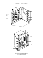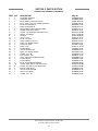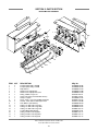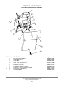
1
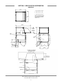
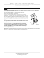
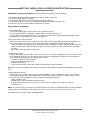
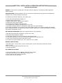
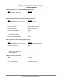
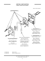
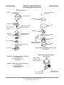
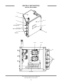
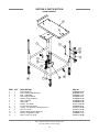
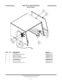
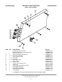
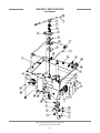
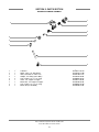
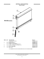
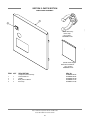
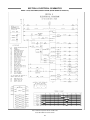
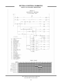
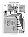
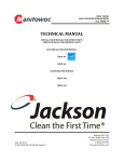
CHEMICAL SANITIZING DISHMACHINE
INSTALLATION, OPERATION
& SERVICE MANUAL
FOR JACKSON MODELS:
Delta 5
Delta 5 D
March 18, 2014
P/N 7610-003-37-08 (Revision F)
Jackson WWS, INC.
P.O. BOX 1060
BARBOURVILLE, KY. 40906
PHONE (606) 523-9795
FAX (606) 523-9196
www.jacksonwws.com
MANUFACTURERS WARRANTY
ONE YEAR LIMITED PARTS & LABOR WARRANTY
ALL NEW JACKSON DISHWASHERS ARE WARRANTED TO THE ORIGINAL PURCHASER TO BE FREE FROM DEFECTS IN MATERIAL
OR WORKMANSHIP, UNDER NORMAL USE AND OPERATION FOR A PERIOD OF (1) ONE YEAR FROM DATE OF PURCHASE, BUT IN
NO EVENT TO EXCEED (18) EIGHTEEN MONTHS FROM DATE OF SHIPMENT FROM THE FACTORY.
Jackson WWS agrees under this warranty to repair or replace, at its discretion, any original part which fails under normal use due to faulty
material or workmanship during the warranty period, providing the equipment has been unaltered, and has been properly installed, maintained
and operated in accordance with applicable factory instruction manual furnished with the machine and failure is reported to the authorized
service agency within the warranty period. This includes the use of factory specified genuine replacement parts, purchased directly from a
Jackson authorized parts distributor or service agency. Use of generic replacement parts may create a hazard and void warranty certification.
The labor to repair or replace such failed part will be paid by Jackson WWS, within the continental United States, Hawaii and Canada, during
the warranty period provided a Jackson WWS authorized service agency, or those having prior authorization from the factory, performs the
service. Any repair work by persons other than Jackson WWS authorized service agency is the sole responsibility of the customer. Labor
coverage is limited to regular hourly rates; overtime premiums and emergency service charges will not be paid by Jackson WWS.
Accessory components not installed by the factory carry a (1) one year parts warranty only. Accessory components such as table limit
switches, pressure regulators, pre-rinse units, etc. that are shipped with the unit and installed at the site are included. Labor to repair or
replace these components is not covered by Jackson WWS.
This warranty is void if failure is a direct result from shipping, handling, fire, water, accident, misuse, acts of God, attempted repair by authorized
persons, improper installation, if serial number has been removed or altered, or if unit is used for purpose other than originally intended.
TRAVEL LIMITATIONS
Jackson WWS limits warranty travel time to (2) two hours and mileage to (100) one hundred miles. Jackson WWS will not pay for travel time
and mileage that exceeds this, or any fees such as those for air or boat travel without prior authorization.
WARRANTY REGISTRATION
To register your product go to www.jacksonwws.com or call 1-888-800-5672. Failure to register your product will void the warranty.
REPLACEMENT PARTS WARRANTY
Jackson replacement parts are warranted for a period of 90 days from date of installation or 180 days from the date of shipment from the
factory, whichever occurs first.
PRODUCT CHANGES AND UPDATES
Jackson WWS reserves the right to make changes in design and specification of any equipment as engineering or necessity requires.
THIS IS THE ENTIRE AND ONLY WARRANTY OF JACKSON WWS. JACKSON’S LIABILITY ON ANY CLAIM OF ANY KIND, INCLUDING
NEGLIGENCE, WITH RESPECT TO THE GOODS OR SERVICES COVERED HEREUNDER, SHALL IN NO CASE EXCEED THE PRICE
OF THE GOODS OR SERVICES OR PART THEREOF WHICH GIVES RISE TO THE CLAIM.
THERE ARE NO WARRANTIES, EXPRESSED OR IMPLIED, INCLUDING FOR FITNESS OR MERCHANTABILITY, THAT ARE NOT SET
FORTH HEREIN, OR THAT EXTEND BEYOND THE DURATION HEREOF. UNDER NO CIRCUMSTANCES WILL JACKSON WWS BE
LIABLE FOR ANY LOSS OR DAMAGE, DIRECT OR CONSEQUENTIAL, OR FOR THE DAMAGES IN THE NATURE OF PENALTIES,
ARISING OUT OF THE USE OR INABILITY TO USE ANY OF ITS PRODUCTS.
ITEMS NOT COVERED
THIS WARRANTY DOES NOT COVER CLEANING OR DELIMING OF THE UNIT OR ANY COMPONENT SUCH AS, BUT NOT LIMITED
TO, WASH ARMS, RINSE ARMS OR STRAINERS AT ANYTIME. NOR DOES IT COVER ADJUSTMENTS SUCH AS, BUT NOT LIMITED TO
TIMER CAMS, THERMOSTATS OR DOORS, BEYOND 30 DAYS FROM THE DATE OF INSTALLATION. IN ADDITION, THE WARRANTY
WILL ONLY COVER REPLACEMENT WEAR ITEMS SUCH AS CURTAINS, DRAIN BALLS, DOOR GUIDES OR GASKETS DURING THE
FIRST 30 DAYS AFTER INSTALLATION. ALSO, NOT COVERED ARE CONDITIONS CAUSED BY THE USE OF INCORRECT (NON-COMMERICAL) GRADE DETERGENTS, INCORRECT WATER TEMPERATURE OR PRESSURE, OR HARD WATER CONDITIONS.
REVISION/
PAGE
REVISION
DATE
A
05-25-2007
MAW
N/A
Release to production.
24
10-04-2007
MAW
7934
Changed cover on power junction box.
10
05-20-2009
ARL
QOF 339
Updated programming page diagram.
B
04-26-2012
RLC
QOF 386
Updated location of door switch on schematic.
C
04-27-2012
RLC
QOF 386
Added EnergyStar logo.
D
03-08-13
RLC
QOF NDB-219 Updated company logo
E
01-23-14
MHH
QOF NDB-238
F
03-12-14
MADE APPLICABLE
BY
ECN
MHH
ECN 8293
DETAILS
Added wiring change schematics. Removed “Stop” page.
Updated warranty information.
Removed page on programming chemical feeder pumps.
Updated drawings for control box assembly, motor & pump
assembly and incoming plumbing assembly.
Added schematics and harness connections.
i
NOMENCLATURE FOR THE MODELS COVERED IN THIS MANUAL
Delta 5
Delta 5 - Low temperature, chemically sanitizing, with a booster tank.
Detergent, rinse aid & sanitizer chemical feeder pumps
Delta 5 D - Dual door. Low temperature, chemically sanitizing, with a booster tank.
Detergent, rinse aid & sanitizer chemical feeder pumps
Model:
Jackson WWS, INC. provides technical support
for all of the dishmachines detailed in this manual.
Jackson strongly recommends that users refer to
this manual before calling technical support staff.
Users should have this manual on hand when
calling technical support. Technical support is
available from 8:00 a.m. to 5:00 p.m. (EST),
Monday through Friday, for service personnel only.
Technical support is not available on holidays.
Call toll free at 1-888-800-5672.
Serial No.:
Installation Date:
Service Rep. Name:
Phone No.:
ii
TABLE OF CONTENTS
SECTION
I.
DESCRIPTION
PAGE
SPECIFICATION INFORMATION
Specifications
Dimensions
2
3
INSTALLATION/OPERATION INSTRUCTIONS
Installation Instructions
Electrical Installation Instructions
Operation Instructions
Chemical Dispensing Equipment
Detergent Control
5
6
7
9
10
III.
PREVENTATIVE MAINTENANCE
12
IV.
TROUBLESHOOTING SECTION
Common Problems
14
PARTS SECTION
Chemical Feeder Pump Assembly
Solenoid Valve Repair Parts
Control Box Assembly
Peripump Box Assembly
Electrical Connection Box Assembly
Frame Assembly
Hood Assembly
Switch Panel Assembly
Tub Assembly
Frame & Motor Assembly
Pump and Motor Assembly
Booster Tank Assembly
Incoming Plumbing Assembly
Door Assembly
Front Panel Assembly
17
18
19
22
23
24
25
26
27
29
31
32
33
34
35
ELECTRICAL SCHEMATICS
Delta 5 (prior to serial # 14A288762)
Delta 5 (after serial # 14A288762)
Delta 5 115 V, 50/60 Hertz, Single Phase
Delta 5 Harness Connections
37
38
39
40
JACKSON MAINTENANCE & REPAIR CENTERS
42
II.
V.
VI.
VII.
iii
SECTION 1:
SPECIFICATION INFORMATION
1
SECTION 1: SPECIFICATION INFORMATION
SPECIFICATIONS
ELECTRICAL REQUIREMENTS:
OPERATING CAPACITY ( NSF RATED):
RACKS PER HOUR
DISHES PER HOUR
GLASSES PER HOUR
WASH PUMP MOTOR HP
29
725
725
OPERATING CYCLES (SECONDS):
VOLTS
115
NORMAL CYCLE:
PH
1
HZ
60
RINSE
HEATER
RATINGS
2KW@110V
3/4
TYPICAL
TOTAL ELECTRICAL
AMPS
CIRCUIT
*16 A
20 AMP
WASH TIME
RINSE TIME
TOTAL CYCLE TIME
45
25
90
* This dishmachine is designed so that the wash motor is never
running when the wash heater is on. Service load is based upon
the higher of the two amperages.
WASH TANK CAPACITY (GALLONS):
1.2
WASH PUMP CAPACITY (GPM):
61
NOTE: Typical Electrical Circuit is based upon (1) 125% of the
full amperage load of the machine and (2) typical fixed-trip
circuit breaker sizes as listed in the NEC 2002 Edition. Local
codes may require more stringent protection than what is
displayed here. Always verify with an electrical service contractor that the circuit protection is adequate and meets all
applicable national and local codes. These numbers are provided in this manual simply for reference and may change
without notice at any given time.
OPERATING TEMPERATURES:
WASH (MINIMUM)
WASH (RECOMMENDED)
RINSE (MINIMUM)
RINSE (RECOMMENDED)
(48.9°C)
(60.0°C)
(48.9°C)
(60.0°C)
120°F
140°F
120°F
140°F
FRAME DIMENSIONS:
WIDTH
DEPTH
DEPTH, WITH FRONT DOOR OPEN
HEIGHT
MAXIMUM WASH
CHAMBER CLEARANCE
WATER REQUIREMENTS:
WATER LINE SIZE NPT
DRAIN LINE SIZE NPT
FLOW PRESSURE
1/2”
2”
20 ±5 PSI
MINIMUM CHLORINE REQUIRED (PPM):
50
(622.3mm)
(641.35mm)
(933.45mm)
(990.6mm)
24 1/2”
25 1/4”
36 3/4”
39”
(292.1mm)
11 1/2”
FRAME DIMENSION (DOUBLE DOOR):
WIDTH
(622.3MM)
DEPTH
(714.375MM)
DEPTH, WITH DOOR OPEN
(1311.275MM)
HEIGHT
(990.6MM)
CHAMBER CLEARANCE
(292.1MM)
24 1/2”
28 1/8”
51 5/8”
39”
11 1/2”
NOTE: Always refer to the machine data plate for specific
electrical and water requirements. The material provided on
this page is for reference only and may be subject to change
without notice.
Delta 5 Installation & Operation Manual 7610-003-37-08
Issued: 05-25-2007 Revised: 03-18-2014
2
SECTION 1: SPECIFICATION INFORMATION
DIMENSIONS
25 1/4
(642 mm)
A - Incoming Water Connection
B - Drain Connection - 2" IPS
C - Electrical Connection Point
NOTE: All vertical dimensions are
at lowest point due to adjustable
bullet feet and may be raised an
additional 2 3/4".
24 1/2
(622 mm)
36 3/4
(933 mm)
11 1/2
(292 mm)
DISH
CLEARANCE
C
C
20
(508 mm)
A
39
(991 mm)
21 1/4
(540 mm)
12 1/4
A
(311 mm)
3 (76 mm)
6 (152 mm)
7 3/4
(197 mm)
B
B
17
(432 mm)
6 3/4 (171 mm)
21 1/4
(540 mm)
Delta 5 Installation & Operation Manual 7610-003-37-08
Issued: 05-25-2007 Revised: 03-18-2014
3
SECTION 2:
INSTALLATION & OPERATION INSTRUCTIONS
4
SECTION 2: INSTALLATION & OPERATION INSTRUCTIONS
INSTALLATION INSTRUCTIONS
VISUAL INSPECTION: Before installing unit check container and machine for damage. A damaged container may be an
indication of damage to the machine. If there is any type of damage to both container and unit, do not throw away the container.
The dishmachine has been inspected at the factory prior to shipping and is expected to arrive in new, undamaged condition.
However, rough handling by carriers or others may result in damage to the unit while it is in transit. If such a situation occurs,
do not return the unit to the manufacturer. Instead, contact the carrier and ask them to send a representative to the site to
inspect the damage, and request that an inspection report be completed. Contact the carrier within 48 hours of receiving the
machine (to report possible freight damage) and the dealer from whom the unit was purchased.
UNPACKING THE DISHMACHINE: Remove the machine from the container and inspect it for any missing parts. If a part is
missing, contact manufacturer immediately.
LEVEL THE DISHMACHINE: The dishmachine is designed to operate while level. This is important to
prevent any damage to the machine during operation and to ensure the best results possible. The unit
is equipped with adjustable bullet feet which can be turned using a pair of pliers. Verify the unit is level
from front to back and side to side before making any electrical or plumbing connections.
Raise
Lower
Frame with Adjustable Foot
PLUMBING THE DISHMACHINE:All plumbing connections must be made to adhere to local, state,
territorial and national codes. The installing plumber is responsible for ensuring the incoming water lines are flushed of debris
prior to connecting to the machine. Note that chips and materials from cutting processes can become lodged in the solenoid
valves and prevent them from opening or closing. Any valves that are found to be fouled or defective because of foreign
matter left in the water line, and any subsequent water damage, are not the responsibility of the manufacturer.
A water hardness test should be performed to determine if the HTS-11 (scale prevention & corrosion control) needs to be
installed. If water hardness is higher than 5 GPG, the HTS-11 will need to be installed. Please contact manufacturer to purchase
the HTS-11.
CONNECTING THE DRAIN LINE: This dishmachine drain requires a minimum 2” NPT piping that
is pitched at least 1/4” per foot. There must also be an air gap between the machine drain line and
the floor sink or drain. If a grease trap is required by code, it should have a flow capacity of
5 gallons per minute.
WATER SUPPLY CONNECTION: Install the water supply line (1/2” NPT minimum) to the dishmachine
line y-strainer using copper pipe. It is recommended that a water shut-off valve be installed between
the main supply and the machine to allow for service. The water supply line must be capable of 20 ±5
PSI “flow” pressure at the recommended temperature as indicated on the data plate.
Drain Connection
PRESSURE REGULATOR: In areas where the water pressure fluctuates or is greater than the
recommended pressure, it is suggested that a water pressure regulator be installed. This dishmachine
does not come with a water pressure regulator as standard equipment.
SHOCK ABSORBER: It is recommended that a shock absorber (not supplied) be installed in the
incoming water line. This prevents water hammer (hydraulic shock)—induced by the solenoid valve as
it operates—from causing damage to the equipment.
Y-Strainer
PLUMBING CHECK: Slowly turn on the water supply to the machine after connecting the incoming fill line and drain line.
Check for leaks and repair as required. Leaks must be repaired prior to operating the machine.
Delta 5 Installation & Operation Manual 7610-003-37-08
Issued: 05-25-2007 Revised: 03-18-2014
5
SECTION 2: INSTALLATION & OPERATION INSTRUCTIONS
ELECTRICAL INSTALLATION INSTRUCTIONS
ELECTRICAL POWER CONNECTION: DISCONNECT ELECTRICAL POWER SUPPLIES & TAG OUT IN ACCORDANCE
WITH APPROPRIATE PROCEDURES & CODES AT THE DISCONNECT SWITCH TO INDICATE THE CIRCUIT IS BEING
SERVICED.
Electrical and grounding conductors must comply with the applicable portions of the National Electric Code ANSI/NFPA 70
(latest edition) and/or other electrical codes.
Refer to the machine’s data plate for machine operating requirements,
machine voltage, total amperage & serial number.
Remove the connection box lid to install the incoming power lines. Install 1/2”
conduit into the pre-punched holes in the back of the connection box. Route the
power wires and connect to the power block and grounding lug. Install the service
wires (L1 and N) to the appropriate terminals as they are marked on the terminal
block. Install the grounding wire into the lug provided. Wires should be firmly secured
in place.
It is recommended that “De-Ox” or another similar anti-oxidation agent be used on
all voltage connections.
VOLTAGE CHECK: Ensure that the machine is off and apply power to the machine.
Check the incoming power at the terminal block and ensure it corresponds to
the voltage on the machine data plate. Do not run the dishmachine if the voltage
is too high or too low. Shut off the service breaker and mark it as being for the
dishmachine. Advise all personnel of the location of the service breaker. Replace
all covers and tighten the screws.
Ground Lug
Power Block
NOTE: Always refer to the machine data plate for specific electrical and water requirements. The material provided on
this page is for reference only and may be subject to change without notice.
Delta 5 Installation & Operation Manual 7610-003-37-08
Issued: 05-25-2007 Revised: 03-18-2014
6
SECTION 2: INSTALLATION & OPERATION INSTRUCTIONS
OPERATION INSTRUCTIONS
OPERATIONAL START-UP AND CHECK: Before proceeding with the start-up, verify the following:
1.
2.
3.
4.
5.
Open the door and verify that the sump strainer is correctly installed in the sump.
Verify that the drain stopper is in position.
Check that the plugs are securely screwed into the ends of the wash arm.
Check that the wash arm is securely screwed into the stationary base and that it rotates freely.
Check the levels in all chemical containers and replace if necessary.
INITIAL START-UP PROCEDURE:
1. Turn on dishmachine:
a) Turn on the incoming power to the machine at the circuit disconnect box.
b) Turn on the dishmachine by pressing the ON/OFF button. The red light will come on.
c) Check voltage at incoming terminals L1& L2. The voltage measured at these points should match data plate voltage.
d) If voltages are in required range, close the control box cover.
2. Fill the rinse booster heater with water:
a) Before the heater element can be energized, the rinse booster heater must be initially filled with water. Damage to the
heater element will occur if the element is not submerged in water. To initially fill the booster heater with water:
i) Press and hold the FILL button to turn on the incoming water solenoid valve. Continue holding the button until water is
heard entering the wash chamber through the airgap, then release the button. The rinse booster heater is now filled
with water.
ii) Turn off the unit by pressing the on/off switch.
3. Enable heater element:
a) For the initial start-up only, the heater element must be enabled. The machine is shipped from the factory with the heater
element disabled. This is done to ensure that the heater element is not damaged by energizing the element without the
element being submerged in water. To enable the heater element:
i) Remove the booster heater cover panel.
ii) Connect the tagged white/blue wires.
iii) Replace heater cover.
iv) Press the on/off switch, heaters will energize to maintain booster heater temperature.
Note: Water must be in the sump while the machine is running to avoid running the pump dry and causing damage to the pump
seal.
4. Adjust dishmachine fill level:
a) If the water level is not between the lines on the drain standpipe, it will require adjustment. Check to ensure that the
recommended water pressure is being supplied to the machine (20 ±5 PSI is required). If the water pressure is correct,
the electronic timer will need adjustment. Use the following steps to adjust the fill time.
i) Open control box cover.
ii) Adjust fill time as per instructions found in this section.
iii) Open and close the door to run a cycle, then check the water level. Adjust as necessary then close the
control box cover.
NOTE: The machine must run a complete cycle to drain and fill. If the machine is not allowed to drain, the water will build up
inside the tub. After the initial fill, the rinse water for the current cycle will become the wash water for the next cycle.
The dishmachine is now ready to proceed with dishwashing.
Delta 5 Installation & Operation Manual 7610-003-37-08
Issued: 05-25-2007 Revised: 03-18-2014
7
SECTION 2: INSTALLATION & OPERATION INSTRUCTIONS
OPERATION INSTRUCTIONS
WARNING: Certain materials, including silver, silver plate, aluminum and pewter, are attacked by sodium hypochlorite
sanitizers (bleach).
PREPARING DISHES: Proper preparation of ware is essential for the smooth and efficient operation of the dishmachine,
resulting in fewer rewashes and using less detergent.
The following steps should be followed to ensure good results:
1. Remove all scraps and soil into a garbage can.
2. Separate and pre-soak silverware.
3. Separate and pre-soak the egg and casserole dishes.
4. Scrape all ware with a brush or spatula.
5. Flush cups, bowls and glasses with running water.
6. Prewash dishware by soaking or spraying with a pre-rinse hose.
7. Place dishes and cups in dish rack. Cups should be upside down so they don’t hold water.
8. Place glasses and flatware in their respective racks. Scatter flatware loosely in rack. Glasses should be placed upside
down in a properly sized rack. For optimal results, flatware should be washed twice, the first being horizontal, the second in
a special rack to hold flatware vertical.
DAILY MACHINE PREPARATION: Before proceeding with start-up, verify the following:
1.
2.
3.
4.
5.
6.
Open door and verify that the sump strainer is in place in the sump.
Verify that the drain stopper is in position.
Check that the plugs are securely screwed into the ends of all wash arms.
Check that the wash arms are securely screwed into the stationary bases and rotate freely.
Check levels in all chemical containers and replace if empty.
For initial fill, close doors and depress the “FILL” switch to the “FILL” position.
WASHING A RACK OF WARE:
1. Open doors, place a full rack into the machine, and close doors. Push the start switch and hold until unit starts
(about 2 seconds).
2. After cycle is completed open doors and remove rack.
3. Repeat steps A and B.
SHUT DOWN AND CLEANING:
1. At the end of mealtime, move the “ON/OFF” switch to the “OFF” position.
2. Open doors and manually remove drain stopper to drain the unit.
3. Remove and clean upper and lower wash arms.
4. Remove and clean the sump strainer.
Delta 5 Installation & Operation Manual 7610-003-37-08
Issued: 05-25-2007 Revised: 03-18-2014
8
SECTION 2: INSTALLATION & OPERATION INSTRUCTIONS
CHEMICAL DISPENSING EQUIPMENT
WARNING: CHLORINE-BASED SANITIZERS CAN BE DETRIMENTAL TO THE MACHINE IF THE
CHEMICAL SOLUTION IS TOO STRONG. SEE A CHEMICAL PROFESSIONAL
TO ENSURE THE DISPENSER IS SET UP CORRECTLY.
This equipment is not recommend for use with deionized water or other aggressive fluids.
Use of deionized water or other aggressive fluids will result in corrosion and failure of materials and
components and will void the manufacturer's warranty.
TO PREPARE CHEMICAL FEEDER PUMPS FOR OPERATION: The Delta 5 dismachines are supplied with detergent, rinse
additive and sanitizer dispensing chemical feeder pumps. Locate the open ends of the chemical tubes with the tube stiffeners
and place each one in the appropriate container.
Red Tubing = Detergent
Blue Tubing = Rinse Aid
White Tubing = Sanitizer
PRIMING CHEMICAL FEEDER PUMPS: Chemical feeder pumps need priming when the machine is first installed or if for
some reason the chemical lines have been removed and air is allowed to enter.
CAUTION: Water must be in the sump and wash tank prior to the dispensing of chemicals.
Sanitizer in concentration is caustic and may cause damage without dilution.
1. Verify that the proper chemical tube stiffener inlet is in the proper container.
2. Use the prime switches located on the control panel at the bottom of the unit to prime each pump.
The switches are clearly marked as to what chemical feeder pump they are assigned to.
3. To prime the pumps, hold the switch in the momentary position until chemical can be observed entering the sump.
4. Detergent is dispensed as required during the wash cycle by the universal timer. The amount of detergent may need to be
increased or decreased depending on water quality and type of detergent.
5. Rinse additive is dispensed as required into the final rinse. The amount of rinse aid may need to be adjusted depending on
water hardness and results.
6. Sanitizer (either chlorine or iodine) is dispensed into the final rinse. The amount of sanitizer may need to be adjusted
depending on the concentration and type of sanitizer used.
7. Please refer to the next page for instruction on adjusting the chemical feeder pumps on the universal timer.
WARNING: Some of the chemicals used in dishwashing may cause chemical burns if they
come in contact with skin. Wear protective gear when handling these chemicals.
If any skin comes in contact with these chemicals, immediately follow the instructions
provided with the chemicals for treatment.
Delta 5 Installation & Operation Manual 7610-003-37-08
Issued: 05-25-2007 Revised: 03-18-2014
9
SECTION 2: INSTALLATION & OPERATION INSTRUCTIONS
DETERGENT CONTROL
DETERGENT CONTROL: Detergent usage and water hardness are two factors that contribute greatly to how efficiently this
dishmachine will operate. Using detergent in the proper amount can become a source of substantial savings. A qualified water
treatment specialist can relate what is needed for maximum efficiency from the detergent.
1. Hard water greatly affects the performance of the dishmachine, causing the amount of detergent required for washing
to increase. If the machine is installed in an area with hard water, the manufacturer recommends the installation of water
treatment equipment.
2. Deposited solids from hard water can cause spotting that will not be removed with a drying agent. Treated water will reduce
this occurence.
3. Treated water may not be suitable for use in other areas of operation and it may be necessary to install a water treatment
unit for the water going to the dishmachine only. Discuss this option with a qualified water treatment specialist.
4. Dishmachine operators should be properly trained in how much detergent is to be used per cycle. Meet with a water
treatment specialist and detergent vendor to discuss a complete training program for operators.
5. Certain dishmachine models require that chemicals be provided for proper operation and sanitization. Some models
may require the installation of third-party chemical feeders to introduce those chemicals to the machine. The manufacturer
does not recommend or endorse any brand name of chemicals or chemical dispensing equipment. Contact a chemical
distributor for questions.
6. Some dishmachines come equipped with integral solid detergent dispensers. These dispensers are designed to accommodate
detergents in a certain-sized container. If applicable, relate this to a chemical distributor upon first contacting them.
7. Water temperature is an important factor in ensuring that the dishmachine functions properly, and the machine's data plate
details what the minimum temperatures must be for the incoming water supply, the wash tank and the rinse tank. If minimum
requirements are not met, there is a possibility that dishes will not be clean or sanitized.
8. Instruct dishmachine operators to observe the required temperatures and to report when they fall below the minimum
allowed. A loss of temperature can indicate a larger problem—such as a failed heater—or could indicate that the hot water
heater for the operation is not up to capacity and a larger one may need to be installed.
Delta 5 Installation & Operation Manual 7610-003-37-08
Issued: 05-25-2007 Revised: 03-18-2014
10
SECTION 3:
PREVENTATIVE MAINTENANCE
11
SECTION 3: PREVENTATIVE MAINTENANCE
PREVENTATIVE MAINTENANCE
PREVENTATIVE MAINTENANCE: The manufacturer of this dishmachine highly recommends that any maintenance and
repairs not specifically discussed in this manual should be performed by qualified service personnel only (find qualified service
agencies in the back of this manual). Performing maintenance on the dishmachine may void a warranty.
By following the operating and cleaning instructions in this manual, users should get the most efficient results from the
dishmachine. As a reminder, here are some steps to ensure that the dishmachine is used properly:
1. Ensure that the water temperatures match those listed on the machine data plate (on the front left of machine).
2. Remove as much soil as possible from dishes before loading into racks.
3. Ensure that all strainers are in place, laying flat in tub and free of soil and debris before operating the machine. To clean
strainers, wipe them out with a rag and rinse under a faucet. For stubborn debris, a toothpick can be used to dislodge any
obstructions from the perforations. Do not beat strainers on waste cans; once bent they will not work properly.
4. If hard water is present, install an HTS-11 into the water line connecting to the dishmachine (see section "Plumbing the
Dishmachine").
5. Ensure that all wash and/or rinse arms are secure in the machine before operating.
6. Ensure that drains are closed/sealed before operating.
7. Do not overfill racks.
8. Ensure that glasses are placed upside down in the rack.
9. Ensure that all chemicals being injected into machine have been verified as being at the correct concentrations.
9. Clean out the machine at the end of every workday as per the instructions in the manual (see section on
"Shutdown & Cleaning").
10. Always contact a qualified service agency whenever a serious problem arises.
11. Follow all safety procedures, whether listed in this manual or put forth by local, state or national codes/regulations.
Delta 5 Installation & Operation Manual 7610-003-37-08
Issued: 05-25-2007 Revised: 03-18-2014
12
SECTION 4:
TROUBLESHOOTING
13
SECTION 4: TROUBLESHOOTING SECTION
COMMON PROBLEMS
WARNING: Inspection, testing and repair of electrical equipment should be performed only by qualified
service personnel. Certain procedures in this section require electrical tests or measurements
while power is applied to the machine. Exercise extreme caution at all times. If test points are not
easily accessible, disconnect power, attach test equipment and reapply power to test.
When replacing electrical parts, disconnect power at source circuit breaker.
Problem: Water overflow from bottom of door.
CAUSE
Clogged drain
SOLUTION
Remove obstruction.
Machine not level
Level machine, or increase height to the front.
Excessive inlet pressure
Install pressure reducing valve, or adjust if one is present. Ensure flow
is 20 ±5 PSI.
Detergent foaming
Reduce detergent quantity.
Excessive fill time
Adjust timer fill time as per Section 2.
Problem: Wash motor doesn’t operate on manual wash.
CAUSE
Loose or broken wires
SOLUTION
Reconnect or replace wires in motor.
Defective manual wash switch
Replace.
Defective motor starting relay
Replace.
Problem: Motor operates on manual wash/delime but not on automatic.
CAUSE
Defective circuit in manual wash switch
SOLUTION
Replace switch.
Problem: No water comes through the rinse arms when the “FILL” switch is depressed.
CAUSE
Water not turned on
SOLUTION
Turn water on.
Defective solenoid valve
Replace solenoid valve.
Problem: Little or no water coming through the rinse assemblies.
CAUSE
Limed up rinse heads or piping
SOLUTION
Delime rinse heads.
Low water pressure
Increase pipe size to machine. Adjust pressure regulator.
Continued on next page.
Delta 5 Installation & Operation Manual 7610-003-37-08
Issued: 05-25-2007 Revised: 03-18-2014
14
SECTON 4: TROUBLESHOOTING SECTION
COMMON PROBLEMS
Problem: Rinse water runs continuously with breaker turned off.
CAUSE
Defective plunger in solenoid valve
SOLUTION
Replace.
Defective diaphragm in solenoid valve
Replace diaphragm.
Problem: Wash temperature not at required reading on thermometer.
CAUSE
Check that white/blue wires are connected
SOLUTION
See note on page 12.
Defective thermometer
Replace.
Defective thermostat
Adjust or replace thermostat.
Rinse heater defective
Replace heater element.
Defective heater contactor R2
Replace.
Incoming inlet water temperature
below required minmum.
Adjust.
Defective heater delay relay (R4)
Replace.
Problem: Rinse water not at required temperature range.
CAUSE
Check that white/blue wires are connected
SOLUTION
See note in installation instructions.
Thermometer is defective
Replace.
Thermostat is defective
Adjust or replace the thermostat.
Incoming rinse water does not meet
minimum criteria indicated on
machine data plate
Adjust as required.
Problem: No indication of pressure.
CAUSE
Water turned off
SOLUTION
Turn water on.
Pressure gauge defective
Replace pressure gauge.
Delta 5 Installation & Operation Manual 7610-003-37-08
Issued: 05-25-2007 Revised: 03-18-2014
15
SECTION 5:
PARTS SECTION
16
SECTION 5: PARTS SECTION
CHEMICAL FEEDER PUMP ASSEMBLY
Squeeze Tube Lubricant
Housing Kit (Red roller)
Mfg. No.: 04320-121-37-10
Motor, 36 RPM 115V
Detergent/Sanitizer Feeder Pump
Mfg. No.: 04320-111-35-14
Motor, 14 RPM 115V
Rinse Aid Feeder Pump
Mfg. No.: 04320-111-35-13
Roller, Red (Detergent/Sanitizer)
Mfg. No.: 04320-111-36-70
Roller, White (Rinse Aid)
Mfg. No.: 04320-002-82-28
Squeeze Tube, Detergent/Sanitizer
(Use with the red roller.)
Mfg. No.: 05700-111-35-29
Clear Squeeze Tube, Rinse Aid
(Use with the white roller.)
Mfg. No.: 05700-011-76-41
Roller, Black
Mfg. No.: 04320-111-65-27
1/4” Sight Tube
3/8” Sight Tube
Tube, Small 7/32”
(Use with the black roller.)
Mfg. No.: 05700-011-65-21
Mfg. No.: N/A
Mfg. No.: 05700-111-35-33
Delta 5 Installation & Operation Manual 7610-003-37-08
Issued: 05-25-2007 Revised: 03-18-2014
17
Motor, 36 RPM 240V
Detergent/Sanitizer Feeder Pump
Mfg. No.: 04320-111-47-47
Motor, 14 RPM 240V
Rinse Aid Feeder Pump
Mfg. No.: 04320-111-47-46
Motor, 14 RPM 24V
Rinse Aid Feeder Pump
Mfg. No.: 04320-011-63-33
SECTION 5: PARTS SECTION
SOLENOID VALVE REPAIR PARTS KITS
Screw
Cap Screw
Data Plate
Coil and Housing
Data Plate
Valve Bonnet
Spring position is moved
for clarity. Goes below
the plunger.
Cap
Spring & Plunger Kit
06401-003-07-40
Cap Retainer
O-Ring & Diaphragm
06401-003-07-41
Diaphragm
Retainer
O-Ring
Plunger
Screen Retainer
Components of Repair
Kit 06401-003-06-23
Mesh Screen
Valve Body
Body
Complete Vacuum Breaker Assembly, 1/2” NPT
04820-003-06-13
Water Hammer Arrestor Assembly
05700-002-64-67
Complete 110 Volt Solenoid Valve Assembly, 1/2”
04810-100-12-18
Water Hammer
Arrestor, 1/2" NPT
06685-100-05-00
Coil & Housing only, 1/2”
06401-003-07-43
Complete 220 Volt Solenoid Valve Assembly, 1/2”
04810-100-09-18
Coil & Housing only, 1/2”
06401-003-07-44
Tee, 1/2” x 1/2” x 1/2”
04730-211-27-00
Delta 5 Installation & Operation Manual 7610-003-37-08
Issued: 05-25-2007 Revised: 03-18-2014
18
Close Nipple, 1/2”
04730-207-15-00
SECTION 5: PARTS SECTION
CONTROL BOX ASSEMBLY
1
9, 10
5
2
6
Normal/Delime
3
7
Rinse Aid/Detergent
8
Sanitizer
4
11, 27
11, 27
14
15
12, 13, 28
Delta 5 Installation & Operation Manual 7610-003-37-08
Issued: 05-25-2007 Revised: 03-18-2014
19
SECTION 5: PARTS SECTION
CONTROL BOX ASSEMBLY
16, 27
32
29
17, 28
19
18, 27
30
17, 28
31
20
21
24, 27
25, 26, 27
27
22, 23
Delta 5 Installation & Operation Manual 7610-003-37-08
Issued: 05-25-2007 Revised: 03-18-2014
20
SECTION 5: PARTS SECTION
CONTROL BOX ASSEMBLY (CONTINUED)
ITEM
QTY
DESCRIPTION
Mfg. No.
1
2
3
4
5
6
7
8
9
10
11
12
13
14
15
16
17
18
19
20
21
22
23
24
25
26
27
28
29
30
31
32
1
1
1
4
1
1
1
1
1
1
2
1
1
4
1
5
2
1
1
1
1
1
2
1
1
1
16
6
1
1
1
1
Control Box Weldment
Control Box Cover
Decal, Warning - Disconnect Power
Screw, 10-32 x 1/2’’ Long, Phillips Tusshead
Decal, Peri-pump Prime
Switch, Delime/Normal
Detergent/Rinse Aid Pump Prime Switch
Sanitizer Pump Prime Switch
Locknut, 1/4”-20 S/S Hex with Nylon Insert
Washer, 1/4”-20 S/S
Contactor
Timer, 8 Cam
Decal, Cam Timer
Fitting, Conduit, Heyco 1/2’’
Fitting, 1/2’’ Straight Snap In
Clamp, 5/8” Nylon
Relay, 2 Pole
Terminal Board
Harness, Switch Panel
Fitting, 1/2’’ 90 Deg. Snap In
Conduit, 1/2” x 40”
Cycle Counter, 115V
Screw, 4-40 x 1/4” Phillips Pan Head
Terminal Board
Terminal Board
Decal, Terminal Board 8 Position
Locknut, 10-24 S/S Hex with Nylon Insert
Locknut, 6-32 S/S Hex with Nylon Insert
Harness, Wash Pump
Harness, Drain Solenoid
Harness, Peri-pump
Conduit, 1/2” x 17”
05700-003-09-42
05700-003-30-54
09905-100-75-93
05305-011-39-36
09905-003-32-56
05930-301-21-18
05930-011-35-27
05930-111-38-21
05310-374-01-00
05311-174-01-00
05945-109-05-69
05945-111-35-32
09905-011-37-21
05975-011-49-03
05975-003-33-27
04730-011-39-01
05945-111-35-19
05940-021-94-85
05700-003-35-37
05975-003-33-28
05700-003-35-48
05990-111-35-38
05305-002-32-38
05940-002-78-97
05940-001-97-91
09905-003-09-30
05310-373-01-00
05310-373-03-00
05700-003-35-34
05700-003-35-36
05700-003-35-35
05700-003-35-49
Delta 5 Installation & Operation Manual 7610-003-37-08
Issued: 05-25-2007 Revised: 03-18-2014
21
SECTION 5: PARTS SECTION
PERI-PUMP BOX ASSEMBLY
7
7
66
99
11
id
eA
5
ns
Ri
15
4
t
1
r
ize
nit
Sa
15
en
rg
te
De
5
8
2
10
33
10
16
11
12
12
18
14
17
13
11
14
11
13
ITEM
QTY
DESCRIPTION
Mfg. No.
1
2
3
4
5
6
7
8
9
10
11
12
13
14
15
16
17
18
2
1
1
1
1
1
1
1
5
3
3
1
1
1
1
1
1
1
Peri-pump Assembly, 36 RPM
Peri-pump Assembly, 14 RPM
Drip Channel
Weldment, Peri-pump Box
Weldment, Peri-pump Box Cover
Fitting, Conduit, Heyco 1/2’’
Clamp, 5/8” Nylon (Located inside of box)
Clamp, 1” Nylon
Screw, 10-32 x 1/2’’ Long, Phillips Tusshead
Locknut, 10-24 S/S Hex with Nylon Insert
Tube Stiffener (Not Shown)
Tubing, 1/4’’ OD x 60” Long, Blue
Tubing, 1/4’’ OD x 60” Long, White
Tubing, 1/4’’ OD x 60” Long, Red
Terminal Board (Not Shown)
Tubing,1/4 OD x 120 Long Blue
Tubing,1/4 OD x 120 Long Write
Tubing,1/4 OD x 120 Long Red
05700-002-96-08
05700-002-96-09
05700-003-32-89
05700-003-32-00
05700-003-33-80
05975-011-65-51
04730-011-39-01
04730-002-41-88
05305-011-39-36
05310-373-01-00
05700-002-66-49
05700-002-52-34
05700-002-52-33
05700-011-63-18
05940-001-97-91
05700-011-37-17
05700-011-37-13
05700-011-37-15
Delta 5 Installation & Operation Manual 7610-003-37-08
Issued: 05-25-2007 Revised: 03-18-2014
22
8
SECTION 5: PARTS SECTION
ELECTRICAL CONNECTION BOX ASSEMBLY
1
5
2
3
7
10
A
A
6
5
4
8
11
A
9
ITEM
QTY
DESCRIPTION
Mfg. No.
1
2
3
4
5
6
7
8
9
10
11
1
1
1
1
5
1
1
1
1
2
1
Box, Power Junction Weldment
Terminal Block Spacer
Terminal Block
Locknut, 6-32 with Nylon Insert
Locknut, 10-24 with Nylon Insert
Lug, Ground
Decal, Power Connection
Decal, Warning to Disconnect Power
Screw, 10-32 x 1/2’’ Long, Phillips Trusshead
Decal, Copper Conductors Only
Cover, Solenoid Box
05700-003-30-58
05700-011-40-05
05940-500-09-61
05310-373-03-00
05310-373-01-00
05940-200-76-00
09905-011-47-64
09905-100-75-93
05305-011-39-36
09905-011-47-35
05700-003-46-72
Delta 5 Installation & Operation Manual 7610-003-37-08
Issued: 05-25-2007 Revised: 03-18-2014
23
SECTION 5: PARTS SECTION
FRAME ASSEMBLY
5
ITEM
QTY
DESCRIPTION
Mfg. No.
1
2
3
4
5
6
7
8
9
10
11
12
13
14
1
1
4
1
1
1
1
8
1
4
5
1
1
1
Frame Weldment
Frame Weldment Double Door
Foot, 3” Adjustable
Plate, Hinge Weldment
Washer, Hinge Weldment
Spacer, PB Bolt
Clamp, Pipe
Washer, 1/4”-20 S/S
Keeper, Door Panel Latch
Locknut, 1/4”-20 S/S Hex with Nylon Insert
Nut, Hex 1/4”-20
Booster Mounting Plate Weldment
Bracket, Temperature Gauge
Bolt, 1/4”-20 x 1/2” Long
05700-003-09-40
05700-003-28-12
05340-002-14-55
05700-003-10-11
05700-002-54-62
05700-000-29-40
05700-000-35-05
05311-174-01-00
05700-003-09-31
05310-374-01-00
05310-274-01-00
05700-002-51-93
05700-003-14-53
05305-274-02-00
Delta 5 Installation & Operation Manual 7610-003-37-08
Issued: 05-25-2007 Revised: 03-18-2014
24
SECTION 5: PARTS SECTION
HOOD ASSEMBLY
ITEM
QTY
DESCRIPTION
Mfg. No.
1
1a
2
3
4
5
6
7
8
1
1
1
1
4
2
2
2
1
Hood Weldment
Hood Weldment Double Door
Switch, 115V Reed
Bracket, Limit Switch
Locknut, 10-24 with Nylon Insert
Clamp, Pipe 5/8”
Rack Rail Weldment
Washer, 1/4”-20 I.D.
Gasket, Side Panel (5.3 Feet)
05700-003-09-56
05700-003-28-17
05930-002-36-80
05700-021-71-18
05310-373-01-00
05700-000-35-06
05700-002-45-67
05311-174-01-00
05700-003-35-51
Delta 5 Installation & Operation Manual 7610-003-37-08
Issued: 05-25-2007 Revised: 03-18-2014
25
SECTION 5: PARTS SECTION
SWITCH PANEL ASSEMBLY
ITEM
1
1a
2
3
4
5
6
7
8
9
10
11
12
13
14
15
QTY
DESCRIPTION
Mfg. No.
1
1
2
1
1
1
1
1
3
6
6
1
1
1
1
1
Complete Side Panel Assembly
Complete Side Fanel Assembly (Double Door)
Side Panel Weldment
Side Panel Weldment (Double Door)
Switch, Prime Assembly
Switch, On/Off Assembly
Light, Amber
Light, Red
Decal, Switch Panel
Fitting, .25-.546
Plug, 3/4” hole
Locknut, 10-24 with Nylon Insert
Washer, #10
Decal Switch Panel (Double Door Only)
Fitting (Double Door Only)
switch (Double Door Only)
bracket (Double Door Only)
Terminal Board
05700-003-24-38
05700-003-24-40
05700-003-24-36
05700-003-24-37
05700-003-14-91
05700-003-14-92
05945-504-06-18
05945-504-07-18
09905-003-08-63
05975-011-65-51
04730-011-60-21
05310-373-01-00
05311-173-02-00
09905-003-38-95
05975-011-49-03
05930-002-36-80
05700-021-71-18
05940-001-97-91
(3)
(2)
(2)
(2)
ALL NUMBERS THAT ARE IN PARENTHESES ARE FOR THE DOUBLE DOOR
Delta 5 Installation & Operation Manual 7610-003-37-08
Issued: 05-25-2007 Revised: 03-18-2014
26
SECTION 5: PARTS SECTION
TUB ASSEMBLY
14b
14a
14c
27b
27a
16a
16b
30e
30d
30b
30c
30a
17c
17b
17a
Delta 5 Installation & Operation Manual 7610-003-37-08
Issued: 05-25-2007 Revised: 03-18-2014
27
SECTION 5: PARTS SECTION
TUB ASSEMBLY CONTINUED
ITEM
QTY
DESCRIPTION
Mfg. No.
1
1a
2
3
4
5
6
7
8
9
10
11
12
13
14
14a
1
1
1
2
1
1
1
23
1
1
2
2
2
2
1
1
1
1
1
1
1
1
1
1
1
1
1
1
18
3
1 (2)
1
1
1 (2)
1
1
3
6
1
1
1
4
1
2
1
1
1
4
1
1
Tub Weldment
Tub Weldment (Double Door)
Lower Manifold Weldment
Manifold Gasket
Drain Seat Insert
Spillway Gasket
Spillway Weldment
Locknut, 1/4”-20 S/S Hex with Nylon Insert
Manifold O-Ring
Modified Casting Wedge
Bolt, 3/8”-16 x 1 1/4” S/S
Washer, 3/8” Bevel-Square Iron
Lockwasher, 3/8”
Nut, 3/8”-16 S/S Hex
Complete Wash Arm Assembly
Wash Arm Weldment w/ End Plugs
Wash Arm End Plugs
Wash Arm O-ring
Wash Arm Bearing Assembly
Sump Strainer
Stand Pipe Weldment
Stopper, Stand Pipe
Drain Link Assembly
Drain Link
Nut, Hex, 5/16”-18
Drain Link Connector
Hair Pin, 1/8” to 1”
Fill Tube Weldment
Washer, 1/4”-20 I.D.
Chemical Tube Grommet
Pivot Plate, Left Door Complete Assembly
Door Pivot Plate Left Weldment
Door Pivot Plate Bearing
Pivot Plate, Right Door Complete Assembly
Door Pivot Plate Right Weldment
Door Pivot Plate Bearing
Bolt, 1/4”-20 x 1/2” Long
Screw, 1/4”-20 x 5/8” Long
Air Gap Weldment
Halo Assembly
Halo Weldment
Spray Nozzle and Receptacle
Gasket, Air Gap
Clamp, 1” Nylon (Not Shown, located on bottom of tub.)
Drain Solenoid Box Assembly
Solenoid Box Weldment
Drain Solenoid, 115V
Locknut, 10-24 with Nylon Insert
Decal, Warning
Solenoid Box Cover
05700-003-09-51
05700-003-28-15
05700-002-45-51
05700-111-35-03
05700-021-34-38
05700-111-34-52
05700-031-37-86
05310-374-01-00
05330-111-35-15
09515-011-46-61
05305-276-10-00
05311-011-35-36
05311-276-01-00
05310-276-01-00
05700-003-31-60
05700-003-31-61
05700-003-31-59
05330-002-60-69
05700-021-35-97
05700-002-60-50
05700-021-33-29
05700-121-35-54
05700-002-45-52
05700-002-40-83
05310-275-01-00
05700-002-38-10
05315-011-60-09
05700-002-45-61
05311-174-01-00
05325-002-42-65
05700-002-45-62
05700-002-45-63
03110-002-45-09
05700-002-52-95
05700-002-52-94
03110-002-45-09
05305-274-02-00
05305-274-24-00
05700-003-23-48
05700-003-23-49
05700-003-16-65
04730-002-55-61
05330-003-24-17
04730-002-41-88
05700-003-09-61
05700-003-35-88
04810-200-11-00
05310-373-01-00
09905-100-75-93
05700-003-30-25
14b
14c
15
16a
16b
17
17a
17b
17c
18
19
20
21
22
22a
22b
23
23a
23b
24
25
26
27
27a
27b
28
29
30
30a
30b
30c
30d
30e
ALL NUMBERS THAT ARE IN PARENTHSES ARE FOR THE DOUBLE DOOR
Delta 5 Installation & Operation Manual 7610-003-37-08
Issued: 05-25-2007 Revised: 03-18-2014
28
SECTION 5: PARTS SECTION
FRAME AND MOTOR ASSEMBLY
10
1
11
See Motor
Assembly
Page
4
2
11
11
3a
3b
See Plumbing
Assembly
Page
See Booster
6
12
Assembly
Page
5
8
9
7
See Frame
Assembly
Page
13
Delta 5 Installation & Operation Manual 7610-003-37-08
Issued: 05-25-2007 Revised: 03-18-2014
29
SECTION 5: PARTS SECTION
FRAME AND MOTOR ASSEMBLY (CONTINUED)
ITEM
QTY
DESCRIPTION
Mfg. No.
1
2
3
3a
3b
4
5
6
7
8
9
10
11
12
13
1
1
1
2
1
1
1
1
8
18
18
1
3
1
1
Discharge Tube Connector
Pump Suction Hose
Discharge Hose Assembly
Fitting, 1/2” Pushlock, Female, Brass
Hose, 1/2” x 22 1/2” Long
Wash Restrictor
Accumulator Strainer Weldment
Accumulator Weldment
Bolt, 1/4”-20 x 1/2” Long
Locknut, 1/4”-20 S/S Hex with Nylon Insert
Washer, 1/4”-20 S/S
Hose Clamp, 13/16 TO 1 1/2”
Hose Clamp, 1 1/16” to 2 1/4”
Close Nipple, 1/2” Brass
Gauge, Thermometer
05700-011-70-34
05700-002-40-82
05700-002-45-58
04730-011-93-99
05700-002-45-59
05700-002-84-69
05700-003-33-25
05700-002-51-95
05305-274-02-00
05310-374-01-00
05311-174-01-00
04730-719-06-09
04730-719-18-00
04730-207-15-00
06685-111-68-48
Delta 5 Installation & Operation Manual 7610-003-37-08
Issued: 05-25-2007 Revised: 03-18-2014
30
SECTION 5: PARTS SECTION
MOTOR & PUMP ASSEMBLY
Complete Pump & Motor Assembly
Mfg. No.: 06105-002-16-29
Pump Only Assembly
Mfg. No.: 05700-002-79-49
Motor Only
Mfg. No.: 06105-002-79-61
Shim Kit
Mfg. No.: 05700-002-82-58
Impeller Assembly
Mfg. No.: 05700-002-81-86
Case Capscrew
Mfg. No.: 05305-002-81-88
Pump Casing
Mfg. No.: 05700-002-84-99
Mechanical Seal
Mfg. No.: 05330-002-34-22
Case O-Ring
Mfg. No.: 05330-002-81-83
Seal Plate
Mfg. No.: 05700-002-81-87
Lockwasher, 3/8”
Mfg. No.: 05311-276-01-00
Motor Mounting Bracket
Mfg. No.: 05700-002-55-52
Nut, Hex 3/8”-16 S/S
Mfg. No.: 05310-276-01-00
Bolt, 3/8” x 3/4” Long Hex Head
Mfg. No.: 05306-011-71-60
Delta 5 Installation & Operation Manual 7610-003-37-08
Issued: 05-25-2007 Revised: 03-18-2014
31
Other parts not shown.
Drain Plug
Mfg. No.: 04730-002-81-89
SECTION 5: PARTS SECTION
BOOSTER TANK ASSEMBLY
13
3
12
10
11
ITEM
QTY
DESCRIPTION
Mfg. No.
1
2
3
4
5
6
7
8
9
10
11
12
13
13a
1
1
1
1
1
1
4
4
2
1
1
1
1
1
Booster Tank Weldment
Heater, 120V, 2000 Watts
Heater Gasket
Thermostat
Fitting, Imperial Brass
Plug, 1/4” Brass
Lockwasher, 5/16”
Nut, 5/16”-18 S/S Hex
Locknut, 6-32 S/S Hex w/ Nylon Insert
Booster Tank Cover
Decal, Warning, Disconnect Power
Screw, 10-32 x 3/8”
Fitting, 1/2” NPT x 90 Deg. Elbow
Nut, 1/2” NPT Nylon
05700-002-45-56
04540-002-45-13
05330-100-01-10
05930-003-13-65
05310-924-02-05
04730-209-01-00
05311-275-01-00
05310-275-01-00
05310-373-03-00
05700-002-39-07
09905-100-75-93
05305-173-12-00
05975-003-35-32
05975-003-35-33
Delta 5 Installation & Operation Manual 7610-003-37-08
Issued: 05-25-2007 Revised: 03-18-2014
32
SECTION 5: PARTS SECTION
INCOMING PLUMBING ASSEMBLY
1
3
2
4
5
6
5
7
8
9
ITEM
QTY
DESCRIPTION
Mfg. No.
1
2
3
4
5
6
7
8
9
1
1
1
1
2
1
1
1
1
Y-Strainer
Nipple, Close, 1/2’’ NPT, Brass
Valve, Solenoid, 1/2’’ NPT, 115V
Adapter, 1/2’’ Fitting (CU to Male)
Tube, Copper, 1/2’’ x 1 1/4’’ Long
Union, 1/2’’, Copper to Copper
Elbow, 607, 1/2’’ Copper to Copper
Tube, Copper, 1/2’’ x 4 1/4’’ Long
Elbow, 90° (CU to MSPS)
04730-217-01-10
04730-207-15-00
04810-100-12-18
04730-401-03-01
05700-001-08-28
04730-412-05-01
04730-406-01-01
05700-001-01-60
04730-406-32-01
Delta 5 Installation & Operation Manual 7610-003-37-08
Issued: 05-25-2007 Revised: 03-18-2014
33
SECTION 5: PARTS SECTION
DOOR ASSEMBLY
Order kit #*****-***-**-**
when replacing magnet.
ITEM
1
2
3
4
5
6
7
QTY
DESCRIPTION
Mfg. No.
2
1
1
2
1
1
1
1
Complete Door Assembly
Door Weldment
Magnet, Reed Switch
Magnet Cover (not shown)
Locknut, 6-32 S/S Hex with Nylon Insert
Locknut, 1/4”-20 S/S Hex with Nylon Insert
Nut, Hex 1/4”-20 S/S
Bolt, 1/4”-20 Eye, S/S
Spring, Door
05700-003-35-30
05700-003-35-29
05930-002-68-53
05700-004-07-38
05310-373-03-00
05310-374-01-00
05310-274-01-00
05306-002-55-59
05340-011-44-58
(2)
(2)
(2)
(2)
(4)
(2)
(2)
(2)
ALL NUMBERS THAT ARE IN PARENTHESES ARE FOR THE DOUBLE DOOR
Delta 5 Installation & Operation Manual 7610-003-37-08
Issued: 05-25-2007 Revised: 03-18-2014
34
SECTION 5: PARTS SECTION
FRONT PANEL ASSEMBLY
Double Door Only
Panel Clips
2 per machine
05340-003-22-95
(Double Door Only)
Back Panel Weldment
1 per machine
05700-003-24-42
ITEM
1
2
3
4
QTY
DESCRIPTION
Mfg. No.
1
1
1
2
Complete Panel Assembly
Panel Weldment
Handle
Back panel weldment
Panel clip
05700-003-09-53
05700-003-09-54
05340-001-96-30
05700-002-24-42
05700-033-22-95
Delta 5 Installation & Operation Manual 7610-003-37-08
Issued: 05-25-2007 Revised: 03-18-2014
35
SECTION 6:
ELECTRICAL SCHEMATICS
36
SECTION 6: ELECTRICAL SCHEMATICS
DELTA 5 115V, 50/60 HERTZ, SINGLE PHASE (PRIOR TO SERIAL # 14A288762)
Delta 5 Installation & Operation Manual 7610-003-37-08
Issued: 05-25-2007 Revised: 03-18-2014
37
SECTION 6: ELECTRICAL SCHEMATICS
DELTA 5 115V, 50/60 HERTZ, SINGLE PHASE (AFTER SERIAL # 14A288762)
Delta 5 Installation & Operation Manual 7610-003-37-08
Issued: 05-25-2007 Revised: 03-18-2014
38
SECTION 6: ELECTRICAL SCHEMATICS
DELTA 5 115V, 50/60 HERTZ, SINGLE PHASE
Delta 5 Installation & Operation Manual 7610-003-37-08
Issued: 05-25-2007 Revised: 03-18-2014
39
SECTION 6: ELECTRICAL SCHEMATICS
DELTA 5 HARNESS CONNECTIONS
Delta 5 Installation & Operation Manual 7610-003-37-08
Issued: 05-25-2007 Revised: 03-18-2014
40
SECTION 7:
JACKSON MAINTENANCE &
REPAIR CENTERS
41
SECTION 7: JACKSON MAINTENANCE & REPAIR CENTERS
ALABAMA TO FLORIDA
ALABAMA
CALIFORNIA
JONES-McLEOD APPLIANCE SVC BARKERS FOOD MACHINERY
1616 7TH AVE. NORTH
SERVICES
BIRMINGHAM, AL 35203
5367 SECOND STREET
(205) 251-0159
IRWINDALE, CA 91706
800-821-1150
(626) 960-9390
FAX: (205) 322-1440
800-258-6999
[email protected]
FAX: (626) 337-4541
[email protected]
JONES-McLEOD APPLIANCE SVC
854 LAKESIDE DRIVE
GCS SERVICE INC.
MOBILE, AL 36693
LOS ANGELES, CA
(251) 666-7278
(213) 683-2090
800-237-9859
800-327-1433
FAX: (251) 661-0223
FAX: (213) 683-2099
ALASKA
RESTAURANT APPLIANCE SERVICE
7219 ROOSEVELT WAY NE
SEATTLE, WA 98115
(206) 524-8200
800-433-9390
FAX: (206) 525-2890
[email protected]
ARIZONA
AUTHORIZED COMMERCIAL
FOOD EQMT. SVC
4832 SOUTH 35TH STREET
PHOENIX, AZ 85040
(602) 234-2443
800-824-8875
FAX: (602) 232-5862
[email protected]
GCS SERVICE INC.
PHOENIX, AZ
(602) 474-4510
800-510-3497
FAX: (602) 470-4511
ARKANSAS
BROMLEY PARTS & SVC
10TH AND RINGO
P.O. BOX 1688
LITTLE ROCK, AR 72202
(501) 374-0281
800-482-9269
FAX: (501) 374-8352
[email protected]
[email protected]
GCS SERVICE,INC.
3717 CHERRY ROAD
MEMPHIS, TN 38118
(901) 366-4587
800-262-9155
FAX: (901) 366-4588
P & D APPLIANCE
4220-C ROSEVILLE ROAD
NORTH HIGHLANDS, CA 95660
(916) 974-2772
800-824-7219
FAX:(916) 974-2774
GCS SERVICE INC.
PHILADELPHIA, PA
(215)925-6217
800-441-9115
FAX: (215) 925-6208
ELMER SCHULTZ SERVICE
COMMERCIAL APPLIANCE SER- 36 BELMONT AVE.
VICE, INC.
WILLMINGTON, DE 19804
281 LATHROP WAY, #100
(302) 655-8900
SACRAMENTO, CA 95815
800-225-0599
(916) 567-0203
FAX: (302) 656-3673
(800) 464-2222
[email protected]
(916) 567-0324 FAX
EMR SERVICE DIVISION
106 WILLIAMSPORT CIRCLE
COLORADO
SALISBURY, MD 21804
GCS SERVICE INC.
GCS SERVICE INC.
(410) 543-8197
SANTA ANA, CA
SHERIDAN, CO
FAX: (410) 548-4038
(714) 542-1798
(303) 371-9054
FLORIDA
800-540-0719
800-972-5314
FAX: (714) 542-4787
FAX: (303) 371-4754
COMMERCIAL APPLIANCE SERGCS SERVICE INC.
HAWKINS COMMERCIAL APPLI- VICE
8416 LAUREL FAIR CIRCLE
S. SAN FRANCISCO, CA
ANCE SERVICE
(650) 635-0720
3000 S. WYANDOT ST.
BLDG 6, SUITE 114
800-969-4427
ENGLEWOOD, CO 80110
TAMPA, FL 33610
(813) 663-0313
FAX: (650) 871-4019
(303) 781-5548
800-282-4718
(800) 624-2117
COMMERCIAL APPLIANCE SER- FAX: (303) 761-5561
FAX: (813) 663-0212
VICE, INC.
[email protected].
[email protected]
6507 PACIFIC AVENUE, SUITE
net
102
METRO APPLIANCE SERVICE
GCS SERVICE INC
STOCKTON, CA 95207
1640 S BROADWAY
MIAMI, FL
(916) 567-0203
DENVER, CO 80210
(305) 621-6666
(800) 464-2222
(303) 778-1126
800-766-8966
(916) 567-0266 FAX
800-525-3532
FAX: (305) 621-6656
FAX: (303) 778-0268
GCS SERVICE INC.
[email protected]
GCS SERVICE INC
SAN DIEGO, CA
ORLANDO, FL
(858) 549-8411
CONNECTICUT
(407) 841-2551
800-422-7278
GCS SERVICE INC.
800-338-7322
FAX: (858) 549-2323
HARTFORD, CT
FAX: (407) 423-8425
INDUSTRIAL ELECTRIC SVC.
(860) 549-5575
5662 ENGINEER DRIVE
800-423-1562
NASS PARTS AND SERVICE, INC.
1144 BELVILLE ROAD, UNIT 359
HUNTINGTON BEACH, CA 92649 FAX: (860) 527-6355
(714) 379-7100
DAYTONA BEACH, FL 32114
SUPERIOR KITCHEN SERVICE
(386) 226-2642
(800-457-3783
FAX: (714) 379-7109
INC.
(800) 432-2795
22 THOMPSON ROAD
(386) 736-7695 FAX
P & D APPLIANCE SVC
WINDSOR, CT 06088
GCS SERVICE INC
100 SOUTH LINDEN AVE.
(888) 590-1899
S. SAN FRANCISCO, CA 94080
(888) 590-1996 FAX
TAMPA, FL
(813) 626-6044
(650) 635-1900
800-282-3008
800-424-1414
DELAWARE
FAX: (813) 621-1174
FAX: (650) 635-1919
[email protected]
FOOD SERVICE EQMT.
2101 PARKWAY SOUTH
BROOMALL, PA 19008
(610) 356-6900
FAX: (610) 356-2038
[email protected]
Delta 5 Installation & Operation Manual 7610-003-37-08
Issued: 05-25-2007 Revised: 03-18-2014
42
SECTION 7: JACKSON MAINTENANCE & REPAIR CENTERS
FLORIDA TO MARYLAND
JONES-McLEOD APPLIANCE
SVC
854 LAKESIDE DRIVE
MOBILE, AL 36693
(251) 666-7278
800-237-9859
FAX: (251) 661-0223
[email protected]
HAWAII
INDIANA
FOOD EQMT. PARTS &
SERVICE CO.
300 PUUHALE RD.
HONOLULU, HI 96819
(808) 847-4871
FAX: (808) 842-1560
[email protected]
GCS SERVICE INC.
INDIANAPOLIS, IN
(317) 545-9655
800-727-8710
FAX: (317) 549-6286
B622 LA PAS TRAIL
INDIANAPOLIS, IN 46268
IDAHO
(317) 290-8060
(800) 410-9794
RESTAURANT APPLIANCE SVC. (317) 290-8085 FAX
7219 ROOSEVELT WAY NE
SEATTLE, WA 98115
IOWA
(206) 524-8200
GOODWIN TUCKER GROUP
NASS PARTS AND SERVICE, INC. 800-433-9390
1376 HEIDE AVENUE
FAX: (206) 525-2890
2900 DELAWARE AVENUE
PALM BAY, FL 32907
[email protected]
DES MOINES, IA 50317
(321) 952-2012
(515) 262-9308
(800) 432-2795
800-372-6066
RON'S SERVICE
(321) 953-0266 FAX
FAX: (515) 262-2936
703 E 44TH STREET STE 10
GARDEN CITY, ID 83714
[email protected]
GEORGIA
(208) 375-4073
CONES REPAIR SVC.
FAX: (208) 375-4402
GCS SERVICE INC
1056 27TH AVENUE SW
ATLANTA, GA
ILLINOIS
CEDAR RAPIDS, IA 52404
(770) 452-7322
(319) 365-3325
800-334-3599
CONES REPAIR SVC.
800-747-3326
FAX: (770) 452-7473
2408 40TH AVE.
FAX: (319) 365-0885
MOLINE, IL 61265
HERITAGE FOODSERVICE
KANSAS
(309) 797-5323
GROUP OF ATLANTA
800-716-7070
GCS SERVICE INC.
2100 NORCROSS PKWY. SUITE
FAX: (309)797-3631
KANSAS CITY, MO
130
[email protected]
(816) 920-5999
NORCROSS, GA 30071
800-229-6477
(770) 368-1465
EICHENAUER SERVICES INC.
FAX: (816) 920-7387
866-388-9837
130 S OAKLAND ST.
FAX: (866) 388-9838
DECATUR, IL 62522
GENERAL PARTS, INC.
(217) 429-4229
1101 E. 13TH STREET
WHALEY FOODSERVICE
800-252-5892
KANSAS CITY, MO 64106
REPAIRS
FAX: (217) 429-0226
(816) 421-5400
109-A OWENS INDUSTRIAL
[email protected]
(800) 279-9967
DRIVE
SAVANNAH, GA 31405
GCS SERVICE INC.
(816) 421-1270 FAX
(912) 447-0827
ELMHURST, IL
KENTUCKY
888-765-0036
(630) 941-7800
FAX: (912) 447-0826
800-942-9689
CERTIFIED SERVICE CENTER
FAX: (630) 941-6048
PIERCE PARTS & SERVICE
127 DISHMAN LANE
BOWLING GREEN, KY 42101
2422 ALLEN ROAD
GCS SERVICE INC.
MACON, GA 31216
ST. LOUIS, MO
(270) 783-0012
(877) 907-0012
(478) 781-6003
(314) 683-7444
800-368-2512
800-284-4427
FAX: (270) 783-0058
FAX: (478) 781-7186
FAX: (314) 638-0135
CERTIFIED SERVICE CENTER
RAMCO BUSINESS PARK
GENERAL PARTS, INC.
4283 PRODUCE ROAD
248 JAMES STREET
LOUISVILLE, KY 40218
BENSONVILLE, IL 60106
(502) 964-7007
(630) 595-3300
800-637-6350
(800) 880-3604
FAX: (502) 964-7202
FAX: (630)595-0006
[email protected]
[email protected]
NASS PARTS AND SERVICE, INC.
1108 SOUTH WOODS AVENUE
ORLANDO, FL 32805
(407) 425-2681
(800) 432-2795
(407) 425-3463 FAX
Delta 5 Installation & Operation Manual 7610-003-37-08
Issued: 05-25-2007 Revised: 03-18-2014
43
CERTIFIED SERVICE CENTER
1051 GOODWIN DRIVE
LEXINGTON, KY 40505
(606) 254-8854
800-432-9269
FAX: (606) 231-7781
[email protected]
GCS SERVICE INC.
LOUISVILLE, KY
(502) 367-1788
800-752-6160
FAX: (502) 367-0400
GCS SERVICE INC.
LEXINGTON, KY
(606) 255-0746
800-432-9260
FAX: (606) 255-0748
LOUISIANA
HERITAGE SERVICE GROUP
1532 RIVER OAKS WEST
NEW ORLEANS, LA 70123
(504) 734-8864
(800) 499-2351
(504) 733-2559 FAX
MAINE
GCS SERVICE INC.
CHELSEA, MA
(617) 889-9393
800-225-1155
FAX: (617) 889-1222
MASSACHUSETTS RESTAURANT SUPPLY
34 SOUTH STREET
SOMERVILLE, MA 02143
(617) 868-1930
800-338-6737
FAX: (617) 686-5331
PINE TREE FOOD EQUIPMENT
175 LEWISTON ROAD
GRAY, ME 04039
(207) 657-6400
(800) 540-5427
(207) 657-5464 FAX
MARYLAND
EMR SERVICE DIVISION
700 EAST 25TH STREET
BALTIMORE, MD 21218
(410) 467-8080
800-879-4994
FAX: (410) 467-4191
[email protected]
SECTION 7: JACKSON MAINTENANCE & REPAIR CENTERS
MARYLAND TO NEW YORK
EMR SERVICE DIVISION
106 WILLIAMSPORT CIRCLE
SALISBURY, MD 21804
(410) 543-8197
888-687-8080
FAX: (410) 548-4038
[email protected]
EMR SERVICE DIVISION
5316 Sunnyside Ave.
Beltsville, MD 20715
(301) 931-7000
800-348-2365
FAX: (301) 931-3060
[email protected]
GCS SERVICE INC.
SILVER SPRING, MD
(301) 585-7550 (DC)
(410) 792-0338 (BALT)
(800) 638-7278
FAX: (301) 495-4410
MICHIGAN
GCS SERVICE INC.
LIVONIA, MI
(248) 426-9500
800-772-2936
FAX: (248) 426-7555
JACKSON SERVICE COMPANY
3980 BENSTEIN RD.
COMMERCE TWSHP, MI 48382
(248) 363-4159
800-332-4053
FAX: (248) 363-5448
GCS SERVICE INC.
GRAND RAPIDS, MI
(616) 241-0200
800-823-4866
FAX: (616) 241-0541
GCS SERVICE INC.
ST. LOUIS, MO
(314) 638-7444
800-284-4427
FAX: (314) 638-0135
KAEMMERLIN PARTS & SVC.
2728 LOCUST STREET
ST. LOUIS, MO 63103
(314) 535-2222
FAX: (314) 535-6205
[email protected]
GENERAL PARTS, INC.
1101 EAST 13TH STREET
KANSAS CITY, MO 64106
(816) 421-5400
(800) 279-9967
(816) 421-1270 FAX
MONTANA
MASSACHUSETTS
MINNESOTA
ACE SERVICE CO.
95 HAMPTON AVE.
NEEDHAM, MA 02494
(781) 449-4220
800-225-4510 MA & NH
FAX: (781) 444-4789
[email protected]
GCS SERVICE INC.
MINNEAPOLIS, MN
(612) 546-4221
800-345-4221
FAX: (612) 546-4286
MASSACHUSETTS RESTAURANT
SUPPLY
34 SOUTH STREET
SOMERVILLE, MA 02143
(617) 868-1930
800-338-6737
FAX: (617) 868-5331
GENERAL PARTS, INC.
11311 HAMPSHIRE AVENUE
SOUTH
BLOOMINGTON, MN 55438-2456
(952) 944-5800
(800) 279-9980
(800) 279-9980 FAX
MISSISSIPPI
GCS SERVICE INC.
CHELSEA, MA
(617) 889-9393
800-225-1155
FAX: (617) 889-1222
GCS SERVICE INC.
HARTFORD, CT
(860) 549-5575
800-723-1562
FAX: (860) 527-6355
SUPERIOR KITCHEN SERVICE
INC.
399 FERRY STREET
EVERETT, MA 02149
(617) 389-1899
(888) 590-1899
(617) 389-1996 FAX
GCS SERVICE INC.
JACKSON, MS
(601) 956-7800
800-274-5954
FAX: (601) 956-1200
GCS SERVICE INC.
MEMPHIS, TN
(901) 366-4587
800-262-9155
FAX: (901) 366-4588
MISSOURI
GCS SERVICE INC.
KANSAS CITY, MO
(816) 920-5999
800-229-6477
FAX: (816) 920-7387
RESTAURANT APPLIANCE SVC.
7219 ROOSEVELT WAY NE
SEATTLE, WA 98115
(206) 524-8200
800-433-9390
FAX: (206) 525-2890
[email protected]
NEBRASKA
GOODWIN - TUCKER GROUP
7535 D STREET
OMAHA, NE 68124
(402) 397-2880
800-228-0342
FAX: (402) 397-2881
[email protected]
NEW HAMPSHIRE
GCS SERVICE INC.
CHELSEA, MA
(617)889-9393
800-225-1155
FAX: (617) 889-1222
ACE SERVICE CO.
95 HAMPTON AVE.
NEEDHAM, MA 02494
(781) 449-4220
800-225-4510 MA & NH
FAX: (781) 444-4789
[email protected]
MASSACHUSETTS RESTAURANT
SUPPLY
34 SOUTH STREET
SOMERVILLE, MA 02143
(617) 868-1930
800-338-6737
FAX: (617) 868-5331
NEW JERSEY
JAY HILL REPAIRS
90 CLINTON RD.
FAIRFIELD, NJ 07004
(973) 575-9145
800-836-0643
FAX: (973) 575-5890
[email protected]
GCS SERVICE INC.
EAST RUTHERFORD, NJ
(973) 614-0003
800-399-8294
FAX: (973) 614-0230
GCS SERVICE INC.
PHILADELPHIA, PA
(215) 925-6217
HI TECH COMMERCIAL SERVICE 800-441-9115
1840 STELLA LAKE STREET
FAX: (215) 925-6208
NORTH LAS VEGAS, NV 89106
(702) 649-4616
ELMER SCHULTZ SERVICES
(877) 924-4832
201 W. WASHINGTON AVE.
FAX: (702) 649-4607
PLEASANTVILLE, NJ 08232
[email protected]
(609) 641-0317
800-378-1641
5454 LOUIE LANE
FAX:(609) 641-8703
RENO, NV 89511
[email protected]
(775) 852-9696
FAX: (775) 852-5104
NEW YORK
NEVADA
GCS SERVICE INC.
LAS VEGAS, NV
(702) 450-3495
800-500-9060
FAX: (702) 450-3491
Delta 5 Installation & Operation Manual 7610-003-37-08
Issued: 05-25-2007 Revised: 03-18-2014
44
APPLIANCE INSTALLATION AND
SERVICE CORP.
1336 MAIN STREET
BUFFALO, NY 14209
(716) 884-7425
800-722-1252
FAX: (716) 884-0410
[email protected]
SECTION 7: JACKSON MAINTENANCE & REPAIR CENTER
NEW YORK TO PENNSYLVANIA
B.E.S.T. INC.
3003 GENESEE STREET
BUFFALO, NY 14225
(716) 893-6464
800-338-5011
FAX: (716) 893-6466
[email protected]
DUFFY'S EQUIPMENT SVC.
3138 ONEIDA STREET
SAUQUOIT, NY 13456
(315) 737-9401
800-443-8339
FAX: (315) 737-7132
[email protected]
NORTHERN PARTS & SVC.
21 NORTHERN AVENUE
PLATTSBURGH, NY 12903
(518) 563-3200
800-634-5005
FAX: (800) 782-5424
[email protected]
GCS SERVICE INC.
BROOKLYN, NY
(718) 486-5220
800-969-4271
FAX: (718) 486-6772
ALL SERVICE KITCHEN
EQUIPMENT REPAIR
10 CHARLES ST.
NEW HYDE PARK, NY 11040
(516) 378-1176
FAX: (516) 378-1735
ALL ISLAND REPAIRS
40-9 BURT DRIVE
DEER PARK, NY 11729
(631) 242-5588
FAX: (631) 242-6102
NORTH CAROLINA
AUTHORIZED APPLIANCE
SERVICECENTER
904 S. MARSHALL ST.
WINSTON-SALEM, NC 27403
(336) 725-5396
FAX:(336) 721-1289
AUTHORIZED APPLIANCE
SERVICECENTER
104 HINTON AVE.
WILMINGTON, NC 28403
(910) 313-1250
FAX:(910) 313-6130
WHALEY FOODSERVICE
8334-K ARROWRIDGE BLVD
CHARLOTTE, NC 28273
(704) 529-6242
FAX: (704) 529-1558
[email protected]
WHALEY FOODSERVICE
REPAIRS
203-D CREEK RIDGE RD.
GREENSBORO, NC 27406
(336) 333-2333
FAX: (336) 333-2533
[email protected]
WHALEY FOODSERVICE
REPAIRS
335-105 SHERWEE DRIVE
RALEIGH, NC 27603
(919) 779-2266
FAX: (919) 779-2224
[email protected]
WHALEY FOODSERVICE
REPAIRS
6418-101 AMSTERDAM WAY
WILMINGTON, NC 28405
(910) 791-0000
FAX: (910) 791-6662
[email protected]
AUTHORIZED APPLIANCE
SERVICECENTER
1020 TUCKASEEGEE RD.
CHARLOTTE, NC 28208
(704) 377-4501
(800) 532-6127
FAX:(704) 377-4504
NORTH DAKOTA
AUTHORIZED APPLIANCE
SERVICECENTER
800 N. PERSON ST.
RALEIGH, NC 27604
(919) 834-3476
FAX:(919) 834-3477
GENERAL PARTS, INC.
10 SOUTH 18TH STREET
FARGO, ND 58103
(701) 235-4161
(800) 279-9987
(701) 235-0539 FAX
GCS SERVICE INC.
MINNEAPOLIS, MN
(612) 546-4221
800-345-4221
FAX: (612) 546-4286
OHIO
OREGON
CERTIFIED SERVICE CENTER
890 REDNA TERRACE
CINCINNATI, OH 45215
(513) 772-6600
800-543-2060
FAX: (513) 612-6600
[email protected]
RON'S SERVICE
16364 SW 72ND AVE
PORTLAND, OR 97224
(503) 624-0890
800-851-4118
FAX: (503) 684-6107
[email protected]
CERTIFIED SERVICE CENTER
171J-K NORTH HAMILTON RD.
COLUMBUS, OH 43213
(614) 751-3769
(866) 862-1252
FAX: (614) 751-5792
[email protected]
PENNSYLVANIA
CERTIFIED SERVICE CENTER
6025 N. DIXIE DRIVE
DAYTON, OH 45414
(937) 898-4040
(800) 257-2611
FAX: (937) 898-4177
[email protected]
COMMERCIAL PARTS & SVC.
OF COLUMBUS
5033 TRANSAMERICA DRIVE
COLUMBUS, OH 43228
(614) 221-0057
800-837-8327
FAX: (614) 221-3622
A.I.S. COMMERCIAL PARTS &
SERVICE
1816 WEST 26TH STREET
ERIE, PA 16508
(814) 456-3732
800-332-3732
FAX: (814) 452-4843
[email protected]
ELMER SCHULTZ SVC.
540 NORTH 3RD STREET
PHILADELPHIA, PA 19123
(215) 627-5400
FAX: (215) 627-5408
[email protected]
GCS SERVICE INC.
PHILADELPHIA, PA
(215) 925-6217
800-441-9115
FAX: (215) 925-6208
GCS SERVICE INC.
COLUMBUS, OH
(614) 476-3225
800-282-5406
FAX: (614) 476-1196
GCS SERVICE INC.
HARRISBURG, PA
(717) 564-3282
800-367-3225
FAX: (717) 564-9286
ELECTRICAL APPLIANCE
REPAIR SVC.
5805 VALLEY BELT ROAD
CLEVELAND, OH 44131
(216) 459-8700
800-621-8259
FAX: (216) 459-8707
[email protected]
GCS SERVICE INC.
PITTSBURGH, PA
(412) 787-1970
800-738-1221
FAX: (412) 787-5005
OKLAHOMA
HAGAR RESTAURANT EQMT.
1229 W MAIN STREET
OKLAHOMA CITY, OK 73106
(405) 235-2184
800-445-1791
FAX: (405) 236-5592
Delta 5 Installation & Operation Manual 7610-003-37-08
Issued: 05-25-2007 Revised: 03-08-2014
45
K & D PARTS AND SERVICE CO.
1833-41 N CAMERON STREET
HARRISBURG, PA 17103
(717) 236-9039
800-932-0503
FAX: (717) 238-4367
[email protected]
CLARK SERVICE & PARTS
306 AIRPORT DRIVE
BOX 10
SMOKETOWN, PA 17576
(717) 392-5590
(717) 392-5735
SECTION 7: JACKSON MAINTENANCE & REPAIR CENTERS
RHODE ISLAND TO WISCONSIN
RHODE ISLAND
GCS SERVICE INC.
EAST PROVIDENCE, RI
(401) 434-6803
800-462-6012
FAX: (401) 438-9400
SUPERIOR KITCHEN SERVICE
INC.
669 ELMWOOD AVENUE
PROVIDENCE, RI 02907
(888) 590-1899
(401) 781-1996 FAX
WHALEY FOODSERVICE
REPAIRS
4740-A FRANCHISE STREET
N. CHARLESTON, SC 29418
(843) 760-2110
FAX: (843) 760-2255
[email protected]
SOUTH DAKOTA
GCS SERVICE INC.
MINNEAPOLIS, MN
(612) 546-4221
800-345-4221
FAX: (612) 546-4286
SOUTH CAROLINA
AUTHORIZED APPLIANCE
SERVICECENTER
1811 TAYLOR ST.
COLUMBIA, SC 29202
(803) 254-8414
FAX: (803) 254-5146
GENERAL PARTS, INC.
10 SOUTH 18TH STREET
FARGO, ND 58103
(701) 235-4161
(800) 279-9987
(701) 235-0539 FAX
TENNESSEE
AUTHORIZED APPLIANCE
SERVICECENTER
2249 AUGUSTA RD.
GREENVILLE, SC 29605
(864) 235-9616
FAX: (864) 235-9623
WHALEY FOODSERVICE
REPAIRS
I 26&US1
P.O. BOX 4023
WEST COLUMBIA, SC 29170
(803) 791-4420
800-877-2662
FAX: (803) 794-4630
[email protected]
WHALEY FOODSERVICE
REPAIRS
748 CONGAREE ROAD
GREENVILLE, SC 29607
(864) 234-7011
800-494-2539
FAX: (864) 234-6662
[email protected]
WHALEY FOODSERVICE
REPAIRS
1406-C COMMERCE PL.
MYRTLE BEACH, SC 29577
(843) 626-1866
FAX: (843) 626-2632
[email protected]
GCS SERVICE INC.
MEMPHIS, TN
(901) 366-4587
800-262-9155
FAX: (901) 366-4588
GCS SERVICE INC.
NASHVILLE, TN
(615) 244-8050
800-831-7174
FAX: (615) 244-8885
TEXAS
ARMSTRONG REPAIR CENTER
5110 GLENMOUNT DRIVE
HOUSTON, TX 77081
(713) 666-7100
800-392-5325
FAX: (713) 661-0520
[email protected]
GCS SERVICE INC.
HOUSTON, TX
(713)785-9187
800-868-6957
FAX: (713) 785-3979
GCS SERVICE INC.
VIRGINIA BEACH, VA
(757) 464-3500
800-476-4278
FAX: (757) 464-4106
GCS/STOVE PARTS
2120 SOLANA STREET
FORT WORTH, TX 76117
(817) 831-0381
800-433-1804
FAX: (817) 834-7754
[email protected]
WASHINGTON
GCS SERVICE INC.
SEATTLE, WA
(206) 763-0353
800-211-4274
FAX: (206) 763-5943
UTAH
RESTAURANT APPLIANCE SERVICE
LA MONICA'S RESTAURANT
7219 ROOSEVELT WAY, NE
EQMT. SVC.
SEATTLE, WA 98115
6182 SOUTH STRATLER AVENUE (206) 524-8200
MURRAY, UT 84107
800-433-9390
(801) 263-3221
FAX: (206) 525-2890
800-527-2561
[email protected]
FAX: (801) 263-3229
[email protected]
WEST VIRGINIA
VERMONT
NORTHERN PARTS & SVC.
4874 S. CATHERINE STREET
PLATTSBURGH, NY 12901
(518) 563-3200
800-634-5005
FAX: (800) 782-5424
[email protected]
GCS SERVICE INC.
CHELSEA, MA
(617)889-9393
800-225-1155
FAX: (617) 889-1222
VIRGINIA
DAUBERS, INC.
7645 DYNATECH COURT
SPINGFIELD, VA 22153
(703) 866-3600
COMMERCIAL KITCHEN REPAIR 800-554-7788
CO.
FAX: (703) 866-4071
1377 N BRAZOS
[email protected]
P.O BOX 831128
SAN ANTONIO, TX 78207
GCS SERVICE INC.
SILVER SPRING, MD
(210) 735-2811
800-292-2120
(301) 585-7550(DC)
(410) 792-0388(BALT)
FAX: (210) 735-7421
800-638-7278
[email protected]
FAX: (301)495-4410
GCS SERVICE INC.
GCS SERVICE INC.
DALLAS, TX
RICHMOND, VA
(972) 484-2954
(804) 672-1700
800-442-5026
800-899-5949
FAX: (972) 484-2531
FAX: (804) 672-2888
Delta 5 Installation & Operation Manual 7610-003-37-08
Issued: 05-25-2007 Revised: 03-18-2014
46
STATEWIDE SERVICE, INC.
603 MAIN AVE.
NITRO, WV 25143
(304) 755-1811
(800) 441-9739
FAX: (304) 755-4001
[email protected]
WISCONSIN
APPLIANCE SERVICE CENTER,
INC.
2439 ATWOOD AVE
MADISON, WI 53704
(608) 246-3160
800-236-7440
FAX: (608) 246-2721
[email protected]
APPLIANCE SERVICE
CENTER, INC.
6843 W. BELOIT RD.
WEST ALLIS, WI 53219
(414) 543-6460
800-236-6460
FAX: (414) 543-6480
[email protected]
APPLIANCE SERVICE
CENTER
786 MORRIS AVE
GREEN BAY, WI 54304
(920) 496-9993
800-236-0871
FAX: (920) 496-9927
[email protected]
SECTION 7: JACKSON MAINTENANCE & REPAIR CENTERS
WISCONSIN TO WYOMING/INTERNATIONAL
GENERAL PARTS, INC.
W223 N735 SARATOGA DRIVE
WAUKESHA, WI 53186
(262) 650-6666
(800) 279-9946
(262) 650-6660 FAX
WYOMING
HAWKINS COMMERCIAL APPLIANCE SERVICE
3000 S. WYANDOT ST.
ENGLEWOOD, CO 80110
(303) 781-5548
(800) 624-2117
FAX: (303) 761-5561
[email protected]
METRO APPLIANCE SERVICE
1640 S BROADWAY
DENVER, CO 80210
(303) 778-1126
800-525-3532
FAX: (303) 778-0268
[email protected]
INTERNATIONAL
GLOBAL PARTS AND SUPPLY
7758 NW 72ND ST
MIAMI, FL 33166
(305) 885-6353
H.D. SHELDON AND CO
19 UNION SQUARE, WEST
NEW YORK, NY 10003
(212) 627-1759
(212) 924-6920
CANADA
THE GARLAND GROUP
1177 KAMATO ROAD
MISSISSAUGA, ONTARIO L4W
1X4
(905) 206-8380
SALES
(905) 624-1419
FAX: (905) 624-1851
SERVICE
800-427-6668
FAX: 800-361-7745
Delta 5 Installation & Operation Manual 7610-003-37-08
Issued: 05-25-2007 Revised: 03-18-2014
47