1
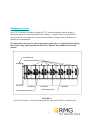
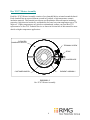
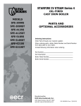
Thermal Control Solution
Installation and
Service Manual
Clamshell Heater
Design
Heat Only Applications
DOC #0100005 Revision 0
Installation & Service Manual
Rex Materials, Inc. retains all proprietary rights in and to the information disclosed here. No part
of this information may be reproduced, copied or used for any purpose without written
permission from Rex Materials, Inc.
Changes and/or corrections to this document may be made periodically. These will be reflected
in subsequent editions, and Rex Materials, Inc. undertakes no commitment to notify the user of
such changes or corrections.
DOC #0100005 First Edition - Revision 0
Printed in the United States of America
Best efforts have been made in the preparation of this document. These efforts include the
development, research, and testing of the theories to determine their effectiveness. However, Rex
Materials, Inc., the author, and the publisher make no warranty of any kind, expressed or
implied, in regard to the use of the theories, instructions, suggestions, or other information
contained in this manual. Each user must depend upon his or her own judgment, knowledge, and
expertise in the interpretation and use of these materials.
2
Introduction
Section One
Introduction and Welcome
4
About This Guide
5
Safety
5
Equipment Overview
7
Rex TCS™ Heater Assembly
8
3
Introduction and Welcome
Thank you for choosing the Rex Thermal Control Solution (Rex TCS™) for the temperature
control needs on your Plastic Injection Molding or Extrusion machines. Rex TCS™ engineers
have designed the Rex TCS™ Barrel Heaters to provide the latest and most efficient barrel
temperature control technology for users seeking to meet the following performance criteria:
Energy Savings - The Rex TCS™ heaters release high radiant energy directly into the barrel
from exposed elements to maximize the heat transfer rate. Exposure of nearly the entire barrel
surface to direct heat increases efficiency. The elements are captured in and protected by a high
temperature ceramic insulating jacket which assures that the heat is contained and directed to the
barrel, rather than heating the work area. The result is dramatically reduced energy usage in the
range of 30-70%.
Faster Thermal Response Time - Traditional barrel heaters must heat themselves before they
begin to conduct heat into the barrel. They also retain considerable residual heat. This results in
considerable lag time before the heat actually affects the barrel. The exposed elements of the Rex
TCS™ heaters transfer heat immediately into the barrel providing much faster heat up and
quicker response times.
Better Temperature Control - The Rex TCS™ System’s direct radiant heating results in faster
response to changing barrel conditions. This reduces set-point overshoot, resulting in much
tighter barrel temperature control (typically better than + 1.0 degree F). This improvement can
result in tighter dimensional control and, thereby, better product quality and less scrap.
Improved Safety and Ergonomics - The Rex TCS™ heater elements are encased in a high
temperature ceramic insulation which stays relatively cool compared to all other types of heaters,
virtually eliminating the chance of burns. The excellent insulation also greatly reduces the
ambient heat around the barrel. Therefore, the Rex TCS™ System contributes to a safer, more
comfortable work environment.
Long Life – Rex TCS™ heaters are designed to provide exceptionally long service life. This
greatly reduces the ongoing replacement cost normally associated with standard barrel heaters.
Quick and Easy Replacement - Rex TCS™ heaters are modular for fast and easy installation
and replacement.
4
About This Guide
This manual will 1) help you plan and prepare for implementing your Rex TCS System,
2) guide you through the installation procedure, 3) introduce you to the principles of its
operation, and 4) describe the maintenance, troubleshooting and repair practices used to achieve
optimum performance from your Rex TCS™ System.
It is not intended to serve as a comprehensive training program. However, it does provide
detailed, easy-to-understand instructions.
If you have any questions that are not addressed by this guide, please consult your Rex TCS™
Sales Representative, or Rex TCS™ Technical Support at the numbers listed below.
Rex TCS™ Technical Support:
Telephone:
Fax:
E-Mail:
Internet:
1-517-223-3787
1-517-223-6822
[email protected]
www.rexmaterials.com
Safety
Safety is a primary consideration in the design of Rex TCS™ Systems. Safety must also be a
priority in its use. This manual provides guidelines and procedures to properly operate and
maintain your Rex TCS™ System. It contains warnings and cautions that must be followed to
reduce the risk of personal injury or damage to the equipment. However, due to the unique nature
of each facility, it is impossible to foresee all of the potential hazards associated with its use. Your
company is solely responsible for determining the adequacy of these recommendations and
providing suitable safety instructions for your facility.
Carefully read and understand this entire document. This important information will maximize
safety, heater performance, efficiency and system life.
All heating elements inherently pose burn, fire and electrical shock hazards. These can result in
injury to personnel or damage to equipment. Care should always be exercised during installation
and use. Do not install heaters in areas where combustible gas, vapor or dust is present.
Only instructed or skilled persons shall be entrusted with the maintenance work of electro heat
installations. No maintenance work shall be carried out with equipment live. Special arrangements
5
(such as locking devices) shall be used to prevent switching-on of the equipment while work is in
progress.
Personnel whose activities involve the operation of electro heat installations or work in the vicinity
shall be notified of the safety requirements to be observed during the operation of the installation by
means of orders or service instructions brought to their attentions by posting up notices or, if
necessary, by handing them a book of instructions for which acknowledgement is obtained. The
responsible persons shall ensure that the safety requirements are observed.
Personnel shall have at their disposal the safety equipment required for carrying out the operations
they are called upon to undertake and for facilitating their intervention in the event of an incident or
an accident. This equipment shall be adapted to the working voltage and maintained in perfect
condition.
Operating the heater above the maximum temperature rating may cause damage to
the machine or heater.
It is recommended that the user install a high temperature protection device where
conditions for an over temperature fault are likely to occur and pose a risk to the
machine or operating personnel. This control should be both functionally and
electrically independent.
Insulate all live electrical connections. Exposed electrical wiring is a violation of
Electrical Safety Codes including O.S.H.A.
Surface temperature of the heaters is highly variable. The “Hot Surface” label supplied with the
TCS System kit should be applied to the machine to alert all operators and maintenance
employees of this danger.
Do not touch the heater surface or Teflon cover during or directly after operation.
Allow heaters to cool before servicing.
6
Equipment Overview
Rex TCS™ Systems are designed using Rex TCS™ System integration software based on
dimensions and specifications provided by the customer. A system can serve any number of
zones. Each zone can contain one or more heater assemblies. Changes in barrel diameter can
normally be accommodated.
If you purchased the barrel or zone cooling option please refer to “Clamshell Heater Design
Heat with Cooling Option Installation and Service Manual” Doc-0100006 instead of this
manual.
CUSTOMER MACHINE
REX TCS HEATER ASSEMBLIES
1 HEATER ZONE
CUSTOMER ZONE THERMOCOUPLE
3 HEATER ZONE
2 HEATER ZONE
CUSTOMER HEATER LEADS
FIGURE 1-1
Rex TCS™ System – General Assembly (Heaters Only with Teflon Covers Removed)
7
Rex TCS™ Heater Assembly
Each Rex TCS™ Heater Assembly consists of two clamshell halves oriented around the barrel.
Each clamshell has an exposed element secured in Pyrolite®, a high temperature ceramic
insulation material. This material provides an excellent balance between superior insulating
properties, high electrical resistivity, and durability for barrel set-point temperatures up to 750
degrees F. Higher temperatures may also be accommodated; contact your local Rex TCS
representative or Rex TCS Technical Service as shown in Section One of this manual for more
details on higher temperature applications.
PYROLITE®
CLAMSHELL HEATER
TERMINAL SCREW
STRAP
JUMPER WIRE
ELEMENT ASSEMBLY
CUSTOMER BARREL
FIGURE 1-2
Rex TCS™ Heater Assembly
8
Installation & Assembly
Section Two
Site Preparation
Overview
10
Heater Clearance and Obstructions
10
Blow Back Prevention
10
Power Supply, Controls and Wiring
10
Thermocouple Adaptors
11
Documenting Savings and Performance Gains
11
Guarding
11
Installation Time and Labor Requirements
11
Final Machine Preparations
12
Removing Packaging and Handling
13
Installation
Overview
14
Rex TCS™ Heater Assembly Installation
15
Rex TCS™ Heater Assembly Wiring
20
Teflon Zone Cover Installation
24
9
Site Preparation
Overview
The installation and start-up of your Rex TCS system can be made much faster and easier
through proper planning and preparation. The areas outlined below require attention well before
the installation date. If you have any questions about these preparations, please contact your
local Rex TCS representative or Rex TCS Technical Service, as shown in Section One of this
manual.
Heater Clearance and Obstructions
Rex TCS heaters require a minimum of 3-1/4 inches of clearance around the full diameter of the
barrel. Please verify that adequate clearance is available and make any machine adjustments
necessary to provide the necessary clearance. Be sure to verify that there is a minimum of 3.25”
clearance around the lead edge of the barrel to the stationary platen when the barrel is in the full
forward position.
One area for special attention is around any barrel support bracket. Make sure that any angled
brace on the foot or other obstruction does not interfere with the 3.25” clearance on the barrel
diameter. Also, verify that the location of the support along the length of the barrel matches that
shown on the drawing/datasheet. If not, adjust accordingly.
The Rex TCS Heater design allows for a certain amount of cutting or trimming to clear small
obstructions or ‘tight spots’. Consult your Rex TCS Rep for details, if necessary.
Blow Back Prevention
Like any heating system, Rex TCS Heaters are subject to damage due to exposure to high
pressure molten plastic that may “blow back” from the molding machine. It is therefore
recommended that a shield or “Purge-away” be installed behind the nozzle to divert any blowback from reaching the heaters. Consult your local Rex TCS Representative or Rex Materials for
recommendations.
Power Supply, Controls and Wiring
Rex TCS heaters can normally be served by the existing electrical power supply and control
system. NOTE: Please verify that the actual power supply to each heater is as specified when
ordering the heaters.
Rex TCS heaters are capable of controlling the barrel temperature within a very tight control
band. While your TCS heaters will perform well with any standard controller, the use of self-
10
tuning controllers is recommended to optimize performance. Also, your existing controller may
be reprogrammed to a tighter control range for less variability in barrel temperature.
If the existing heater wires or their insulation have been damaged due to exposure to excessive
heat from the old heaters, the wiring to the heaters should be replaced. See also Section Two of
this manual under the heading - Rex TCS™ Heater Assembly Wiring.
Rex Materials can advise you about your wiring scheme and control strategy upon request.
However, because every control system is unique and we cannot control plant conditions, we do
not perform any wiring or take any responsibility for power supply or control circuitry.
Thermocouple Adaptors
Due to the 3” thick insulation on the Rex TCS heaters, it is recommended to install 3 ½” or
longer thermocouple port extension adaptors.
NOTE: It is important to order these well in advance of installation to assure availability
Documenting Savings and Performance Gains
If you need to document the energy savings and performance gains you achieve with your Rex
TCS Barrel Heaters, it is vital to gather data using your existing heaters before they are removed.
We recommend recording the power consumption for a period of at least two hours of normal
operation. Be sure to note the product / material being run, temperature set points, cycle times,
shot size and any other significant process variables, so they can be duplicated for the “After”
trials.
It is also important to record the range of barrel temperature variation around the set point to
confirm the improvement in temperature control accuracy that you have achieved.
Also accurately record the time required to heat the barrel to set point from a cold start.
Guarding
Rex TCS heaters have a much lower surface temperature than conventional heaters, so the need
for guarding to protect against burns is normally eliminated.
However, Rex Materials does recommend guarding to protect the heaters from possible damage
due to work done on or around the heaters.
Installation Time and Labor Requirements
Your new Rex TCS Heater System can normally be installed within 3-6 hours, given that the old
heaters have been removed and the barrel prepared. This excludes any time required for rewiring
or control modifications. It is ideal to have at least two people involved during the complete
installation, especially if the barrel is not easily accessible. This also assures that more than one
person is trained on the installation procedures.
11
Final Machine Preparations
In-order to properly install your new Rex TCS™ System, the following machine preparation
steps must be completed prior to installation.
1. Gather the tools and materials listed on the
left, which will be required to install a typical
Rex TCS™ System.
2. Lock-out power to existing barrel heaters.
Tools/Materials Required
Round File 12” Lg x ½”
minimum Dia.
Torque socket wrench ¼”
drive, Set @ 26 in/lbs with
3/8” hex socket
3/8” Open end wrench
Precision Flat-head
screwdriver
Portable shop vacuum
Safety knife
Needle nose pliers
Tape measure
Small hack saw blade
Wire cutters/strippers
3. Make sure the barrel has cooled to a safe
working temperature per customer safety
requirements (below 140 F preferred).
4. Disconnect electrical connections and
completely remove all existing heaters and
thermocouples.
5. Remove any barrel surface contamination to
assure heating is applied directly to the
barrel. Simply wiping the barrel with a cloth
may be sufficient. If there is scale or plastic
buildup, use steel wool, wire brush or tools
as necessary to remove it. The ideal result is
a clean, dry and smooth barrel with no
remaining oil, dirt or moisture.
6. Grind off any metal burrs protruding from the barrel.
7. Verify barrel dimensions (diameter(s), lengths, thermocouple locations, etc.). Any variations
from the original customer specifications can more easily be accommodated at this stage than
after the installation has begun. If measured barrel dimensions do not match customer
supplied design specifications, component modifications or replacements may be required.
Contact Rex Materials immediately if discrepancies are found.
8. Caution – It is very important that the barrel be electrically grounded to prevent possibility of
electrical shock. Test with continuity tester to insure good conductivity between barrel and
machine ground.
12
Removing Packaging and Handling
Your Rex TCS™ System has been palletized to allow the use of a lift truck for unloading and
transport to the work site.
CARE REQUIRED
BE SURE THAT BOXES CONTAINING YOUR REX TCS HEATER ASSEMBLIES
DO NOT HAVE ANYTHING STACKED ON TOP OF THEM.
CARE REQUIRED
HEATERS ARE FRAGILE: TAKE CARE NOT TO DAMAGE THE HEATERS
WHEN REMOVING PACKAGING OR DURING HANDLING.
Most items have individual labeling, but some components are identified only on the box label.
Refer to the Installation Bill of Materials to help identify them during the installation process.
NOTE: Inspect TCS Heaters to assure that they arrived complete and in good condition.
CARE REQUIRED
HEATERS MUST BE STORED IN A DRY LOCATION.
HEATER REFRACTORY CAN ABSORB MOISTURE AND, IF SO,
IT MUST BE THOROUGHLY DRIED PRIOR TO INSTALLATION AND USE.
13
Installation
Overview
This section provides step-by-step instructions for installing your new Rex TCS barrel heaters.
It is recommended that you carefully read the entire section before beginning the installation. Also,
please assure that all preparations described in the previous section are complete.
A minimal amount of cutting and trimming of the heaters is acceptable when proper clearance
cannot be achieved at the time of installation. Do not trim the material to a thickness of less than
1.0" from the embedded elements; as you will begin to lose insulating properties. The portion to be
trimmed should be measured and marked to clear the obstruction, and carefully 'sawed' off with a
small hack saw type blade. The terminals and wires must not be modified. Be sure to use proper
dust collection methods when performing modifications. Be very cautious when doing any
modification to your system in order to reduce the risk of damage to the heaters and insulation.
CAUTION
HANDLING PYROLITE® MATERIALS MAY BE IRRITATING TO THE SKIN, EYES,
AND RESPIRATORY TRACT. WEAR GLOVES AND WASH WITH SOAP AND
WATER AFTER HANDLING. USE OF A DUST MASK AND / OR DUST
COLLECTION IS RECOMMENDED WHEN SAWING, SANDING OR OTHER DUST
GENERATING OPERATIONS ARE DONE.
14
Rex TCS™ Heater Assembly Installation
1.
Identify the first heater to be installed. Each Rex TCS Heater can be identified by the part
number marked on the Heater. The marking also shows the heater voltage and wattage.
Refer to the Installation Bill of Material for correct location of heaters.
CARE REQUIRED
HEATERS ARE FRAGILE: TAKE CARE NOT TO DAMAGE THE HEATERS WHEN
REMOVING PACKAGING OR HANDLING.
WHENEVER POSSIBLE, THE HEATERS SHOULD BE HANDLED BY THE OUTSIDE.
GRIPPING THEM BY THE INSIDE MAY DISPLACE THE HEATER ELEMENT.
2.
Replace thermocouple adaptors with a longer
adaptor if the existing adaptor is shorter than
3.5”. 4” adaptor length is recommended.
Thermocouple adaptors are not included in the
TCS System kit.
15
3.
TCS-0xxxxx TCS System kit
Zone Qty per Item Number
zone
1
2
TCS-120xxx
1
2
TCS-070xxx
1
2
TCS-060xxx
1
1
TCS-060xxx
2
2
TCS-120xxx
2
2
TCS-070xxx
2
2
TCS-060xxx
2
1
TCS-060xxx
Description
TCS HTR HALF x.xD I2.0L 480V xxxxW
TCS HEATER STRAPS x.xD
TCS ZONE COVER x.xD x.xW 32.0C
TCS JUMPER WIRE x.xL
TCS HTR HALF 5.5D x.xL 480V 5290W
TCS HEATER STRAPS x.xD
TCS ZONE COVER x.xD x.xW 32.0C
TCS JUMPER WIRE x.xL
Review the installation BOM for your specific machine make, model and size to identify all parts
needed for each zone.
4.
Measure distance A from starting point on the feed end of the barrel to the center of the first
thermocouple. The starting point should be the edge of the feed end platen or bolt heads.
16
5.
No terminals
on the back
side in this case
Check before installing! Heater halves are supplied with two terminal connections on each half.
The two terminals on a half could be on the same or opposite sides depending upon the length of
the heater. In the case where both terminal connections are on the same side of each half, the
heaters should be installed such that all four terminals are on the same side of the barrel.
6.
Use measurement A from step 4 to locate where the thermocouple will lie within the first set of
heater halves. If zone is long, thermocouple may lie within the second set of heater halves. Use a
5/8” diameter round file to cut half of the thermocouple hole on each heater half. Do not exceed
3/8” depth of cut on either half!
17
7.
Place the heater halves on the barrel, and place the strap(s) around the heater. Two straps are
supplied for any heater 9.25” or longer. Move to step 8 before tightening the strap!
8.
Add/remove gasket
material on heater ID
for minor adjustment
as needed.
Secure the heater firm to the barrel by fastening the strap(s) to a maximum of 10
in-lb. Heater should not be movable by hand when tight, but over tightening can
cause damage to the heater.
18
9.
B
Measure dimension B from edge of the first installed zone to the center of the next
zone thermocouple.
10.
Repeat installation steps for each zone. There should be little or no gap between
zones, and the last heater will generally stop short of the end cap.
19
Rex TCS™ Heater Assembly Wiring
CAUTION
TO AVOID POSSIBLE INJURY,
DISCONNECT MAIN POWER SUPPLY
BEFORE WIRING REX TCS™ HEATER ASSEMBLIES.
Use of “LOCK-OUT, TAG-OUT” PROCEDURES IS HIGHLY RECOMMENDED
Each Rex TCS Heater Assembly must be wired to the minimum specifications below and in
accordance with customer’s standard wiring practices.
1. Customer supplied lead wire should be rated for exposure to a minimum of 250 degrees C.
We use and recommend 14 GA, Type MGT, 450 Deg C.
Cut customer supplied lead wire lengths to suit locations of all Rex TCS™ Heater Assemblies.
Allow sufficient wire length to run the lead wires under the Zone Covers as shown in Figure 23.
NOTE: It is extremely important to apply the correct voltage to each heater half. Refer to the
voltage marked on each heater half. In rare cases with four heater halves in a zone, it may be
necessary to wire all four in series or a combination so that zone voltage is properly divided.
20
SINGLE ZONE
2 HALF HEATERS IN SERIES
SINGLE ZONE
2 HALF HEATERS IN PARALLEL
JUMPER WIRE
SUPPLIED WITH
KIT
JUMPER WIRE
NOT SUPPLIED
WITH KIT
SINGLE ZONE
4 HALF HEATERS IN SERIES
JUMPER WIRE
SUPPLIED WITH
KIT
JUMPER WIRE
NOT SUPPLIED
WITH KIT
JUMPER WIRE
SUPPLIED WITH
KIT
HEATER WIRING SCHEMATIC
Applying higher than the actual rated voltage to the heaters will increase the
watt density which can lead to premature failure and/or damage to barrel.
Verify that an “over-current” device (ex: fuse) is installed to prevent the heater
from being subject to higher amperage than the heater is rated for. See heater
markings for rated amperage.
21
NOTE: ALL HEATERS IN A SINGLE ZONE ARE CONTROLLED
BY THE SAME TEMPERATURE CONTROLLER, BUT
ARE NORMALLY NOT WIRED IN SERIES.
CUSTOMER MACHINE
REX TCS HEATER ASSEMBLIES
1 HEATER ZONE
CUSTOMER ZONE THERMOCOUPLE
3 HEATER ZONE
2 HEATER ZONE
INSTALL CUSTOMER SUPPLIED HEATER
LEADS. SEE TERMINAL CONNECTION VIEW
FIGURE 2-1
REX TCS™ HEATER LEAD WIRE VIEW
NOTE: Fig. 2-1 shows heater terminals on one side. Depending on heater length,
terminals may be on alternating sides.
CAUTION
TO PREVENT PREMATURE HEATER FAILURE,
EACH ASSEMBLY MUST BE CONNECTED TO THE PROPER VOLTAGE
AS INDICATED ON THE HEATER ASSEMBLY.
2. Remove ceramic terminal caps, hex nuts, washers, and loose ring terminals from Heater lead
wire terminals (no jumper wire). Remove 5/16” of jacket from customer supplied lead wires
and crimp ring terminals onto wires. Make sure terminal bar is free of mold flashing.
Reinstall the lead wire with ring terminal, flat washer, lock washer and the hex nut. Hold the
heater terminal with 3/8” open end wrench when tightening the nut. Torque the hex nut to 26
in-lbs, and replace the ceramic cap. See Figure 2-2.
NOTE: Do not torque nuts without holding the heater terminal with wrench, as heater
damage may result from twisting the elements.
22
CERAMIC CAP
CERAMIC COVER
NUT
LOCK WASHER
FLAT WASHER
RING TERMINAL
TERMINAL STUD
FIGURE 2-2
REX TCS™ HEATER TERMINAL CONNECTION VIEW
Check before wiring!
Note the voltage printed on each heater half and also specified on the BOM
document. Heaters are rated in halves and must be wired in series when line
voltage is higher than the marked heater voltage. See figure 2-2 prior to
making electrical connections.
Care required! Electrical connections require 26in-lb tightness. Use 3/8 a wrench
to hold the terminal in place while tightening the nut to prevent potential damage
due to twisting the terminal.
3. Heaters within the same zone are controlled by the same temperature
controller. Verify that the voltage supplied to each heater is in accordance with
the voltage marked on the heater. Refer to customer temperature controller
literature for controller wiring.
23
Teflon Zone Cover Installation
Teflon Zone Covers are used to cover small gaps between Heaters and to protect the Heater’s
outside surfaces from contamination. Cover installation steps are as follows:
1. Wrap Teflon Zone Covers around Heaters and tuck in excess tail under the lead edge of the
cover. See Figure 2-3 & 2-4.
2. Trim or cut holes in Zone Covers for thermocouple adapters (and sensors). See Figure 2-3 & 24.
3. Run Lead Wires under Zone Covers and out Zone Cover ends. See Figure 2-3 & 2-4.
2
1
TRIM COVERS AROUND
THERMOCOUPLE ADAPTERS
ZONE 3
WRAP TEFLON ZONE COVERS AROUND HEATERS
AND TUCK IN EXCESS TAIL
ZONE 1
ZONE 2
RUN LEAD WIRES UNDER ZONE COVERS
AND OUT ZONE COVER ENDS
3
FIGURE 2-3
Teflon Zone Cover Installation View
24
Cut the Teflon cover
flap as needed to
allow for wires and
thermocouple adaptors.
Install Teflon cover with flap over the terminals,
and fasten with silicone O-rings. Wires can be
neatly routed underneath the flap in the Teflon
cover or captured outside the flap by O-rings.
FIGURE 2-4
This completes the installation of your Rex TCS Heater System.
25
Operation & Maintenance
Section Three
Operation
Overview
27
Rex TCS Pre-Start Inspection and Checklist
27
Rex TCS System Start-up
28
Temperature Control and Monitoring
28
Documenting Savings and Performance Gains
29
Maintenance & Repair
Overview
29
Routine Inspection
29
Heater Troubleshooting
30
Barrel Overheating
30
Heater Repair and Replacement
31
26
Operation
Overview
Before applying power to your new Rex TCS™ System, it is important to verify that all
assembly and wiring procedures have been properly performed. Then we will review the normal
operation of the Rex TCS System and discuss how to monitor its performance.
Rex TCS Pre-Start Inspection and Checklist
Prior to switching on the power to your Rex TCS System, please review the following checklist
to assure that all components have been installed in accordance with Section Two of this manual.
Please verify the following:
□ All Rex TCS Heaters are tight on the barrel with no gaps between heaters
□ Double check that the power supply voltage to each heater is per its design
□ Check that barrel is properly grounded. See page 12.
□ Lead wires are in good condition and securely fastened at all connections
□ All heaters in a given zone are controlled by the same temperature controller
□ All temperature controllers are functioning correctly
□ All thermocouples and sensors are mounted and adjusted to seat properly
□ All Teflon Zone Covers are installed and secured with o-rings
□ All wires are neatly routed, secure, and protected
27
Rex TCS System Start-up
Once the Rex TCS System has been installed and checked, it is time to switch on the power and
start the initial heat up. It is recommended that the initial set point be 300 F and that once the
barrel reaches this temperature, it be held there for 15-20 minutes to verify proper heater function
and control system performance.
During this initial period, you may see or smell a small amount of ‘burn-off’ from the small
amount of organic binders in the heaters. Any emissions are non-toxic, but some degree of
ventilation may be useful to minimize any inconvenience.
This is the time to re-check that the barrel temperature thermocouples are properly seated and
functioning properly.
It is also a good idea to inspect the heater connections. If any are seen to be glowing orange, it
indicates that they are not sufficiently tightened to make a good connection.
To correct the problem the glowing positions should be carefully noted and then the heating
system shut down. Remove the Teflon Zone Covers and the ceramic insulator cap from the
position and check the tightness of the nut using the torque wrench set at 26 in-lbs. Remember to
hold the base of the terminal to prevent the terminal from twisting when applying force to the
terminal nut. If the nut is already tightened to the torque value, do not over tighten. Instead,
remove the nut, washers and connector. Check for and remove any debris or mold flashing on
the stud or base. Then re-assemble the connection and re-tighten with the torque wrench, as
above. Use of a high temperature lubricant or anti-seize may help to achieve a better connection.
After the initial check-out period at 300 F, you can ramp up the barrel temperature set point to
the desired operating temperature. Once the barrel is stabilized at the target temperature, you can
begin normal production using your standard practice.
Temperature Control and Monitoring
If you are controlling your Rex TCS heaters using an auto-tune type controller, the system will
very quickly begin to control the barrel temperature to within a very tight control band.
Typically this is within + 1.0 F. It may tune to the point that the readout never varies from the
set point (i.e., less than + 0.5 F). If you do not have auto-tune controllers, you will need to
manually tune the controllers to optimize the control band.
You may also wish to tighten the set points for any over or under temperature alarms to provide
the quickest possible response to any malfunction.
Increasingly, customers are using continuous data-logging systems to monitor the performance of
their machines. This provides an excellent quality control and diagnostic tool to further optimize
the process.
28
Documenting Savings and Performance Gains
If you wish to confirm the energy savings you achieve with your Rex TCS Barrel Heaters, it is
necessary to gather performance data with your existing heaters before they are removed as
described on Section Two of this manual. If you have done so, it is now time to again record the
power consumption and heater on-time for a period of at least two hours of normal operation. Be
sure that the product / material being run and any other significant process variables and
conditions are the same as during the “Before” measurements.
Once you have tuned the controllers, again record the range of barrel temperature variation
around the set point, so that you can confirm the improvement in temperature control accuracy
that you have achieved. You may find that this improved process control translates into
significant and measurably improved product quality control and higher yield.
Accurately record the time required to heat the barrel to set point from a cold start. This is
normally reduced by more than half compared to band heaters. This should translate to higher
machine utilization or at least reduce the need to bring people in early to start up the heaters.
Maintenance & Repair
Overview
One of the major benefits of the Rex TCS Barrel Heating System is that there is no routine or
preventive maintenance required. In fact, barring any mechanical damage or electrical
malfunction, the heaters can be expected to give years of trouble free service.
However, to avoid any failures, it is recommended to occasionally inspect the heaters and their
electrical connections, as described below.
Routine Inspection
Mechanical Damage – Rex TCS Heaters are made from Pyrolite vacuum-formed ceramic fiber
material, which is relatively fragile. Therefore, the potential exists for mechanical damage due
to physical abuse. The good news is that the units are quite robust and often damage can be
repaired as long as the electrical elements and terminals are intact.
See Heater Repair section below for details.
The O-rings on the Teflon covers hold the cover in place on the heater. It is recommended that
they be inspected annually. Replace any O-ring that exhibits signs of melting or cracking.
29
The terminals on the heaters absorb a lot of heat throughout the life of the heater and can cause
the terminal connection to become loose. It is recommended the terminals be re-tightened with a
torque wrench to prevent a poor connection from causing the terminal to overheat and fail. Refer
to Figure 2-2 in the installation manual for proper torque procedure and specification. Replace
Ceramic Cap and Ceramic Insulator when finished.
Thermocouples – Improperly seated or malfunctioning thermocouples are a common problem.
It is strongly advised to confirm that all thermocouples are fully inserted and properly seated
prior to every start-up of the machine, but especially when the tube extensions are first installed.
Worn thermocouples should be replaced on a preventive basis to avoid unplanned shut down of
the machine and reduce the potential for heater and/or barrel damage.
Heater Troubleshooting
The procedures below are offered for diagnosing problems that may be experienced:
Barrel Zone Not Heating Up Properly or Temperature is Dropping from the Set-point
1. Verify that the controller is at the proper set point and is calling for power.
2. Check that the thermocouple controlling the zone is seated properly and functional.
3. Check that current is flowing through the wires to the heater assembly using a clamp on amp
meter.
4. If not, verify that the relay serving the heater is functioning properly. If the relay is not stuck,
it indicates that one of the heater halves has failed. It will be necessary to shut down the machine
and lock out the power supply to the heater and then proceed to the next section.
Diagnosing a Failed Heater Assembly
1. Disconnect one of the power supply leads. Use a meter to check the continuity of the entire
heater assembly across the power supply terminals.
2. If there is not continuity through the heater assembly, check the continuity of each heater half
individually to identify the one that has failed.
Connectors Glowing – Glowing at any terminal connection on the heater assembly indicates
that the connection is not secure and may fail rapidly. If this is observed, mark or carefully note
the terminal location, then shut down machine operation immediately. Lock out the power
supply to the heater, remove the Teflon covers, and re-tighten the connection as described in
Section Three of this manual.
30
Barrel Overheating
If the zone temperature goes above the set point beyond the normal control range it could be
caused by:
• Thermocouple is improperly located or switched with another zone thermocouple.
• Thermocouple not seated properly in the adapter.
• Thermocouple damaged.
If none of the above conditions exist, the overheating could be caused by excessive shear heat
generated by the screw in combination with the excellent insulating properties of the TCS heater
which prevents the heat from escaping, causing an over temp condition.
The excessive shear heat is wasted energy and should be minimized if possible by reducing the
screw RPM or increasing the zone temperature of the previous zone to decrease the viscosity of
the material entering the shear zone.
If you are unable to reduce the temperature to an acceptable level, contact your TCS™ sales
representative or Rex TCS Technical Support.
Heater Repair and Replacement
Heater Repair – If the insulating refractory of a heater has been damaged or broken, it may be
possible to patch or repair it as long as the heater element and terminal are still sound.
NOTE: Check continuity before doing repairs to avoid needless work.
If a corner or small piece of the pad has broken off, it may be reattached using the high
temperature cement supplied in your Rex TCS repair kit. Small punctures or broken areas can be
filled or patched using Pyrolite E-Z Fill available from Rex Materials and provided in the repair
kit.
CAUTION: If cement or E-Z Fill are used in contact with heater terminals or element
wires, the products must be thoroughly dried before power is supplied to the unit to avoid
potential electrical hazard. Allow 24 hours for air drying.
31
Appendix
Section Four
How to Order Spare Parts
33
32
How to Order Spare Parts
The Rex TCS Heaters and End Rings if used are custom made to fit the specific machine
requirements and are not normally stocked by Rex Materials.
It is strongly recommended that the Customer stock at least one heater half for each different
heater assembly on the machine.
Spare parts should be ordered from the authorized TCS distributor where you purchased the
original TCS system.
You can also contact Rex Materials Customer Service Department for assistance in identifying
correct spare parts.
Telephone:
Fax:
E-Mail:
1-517-223-3787
1-517-223-6806
[email protected]
When ordering spare parts, include the TCS-xxxxxxx part number, the description as shown on
the Heater or Installation Bill of Material.
33