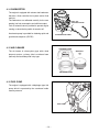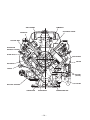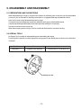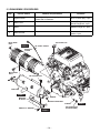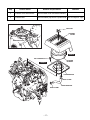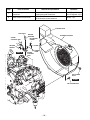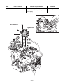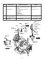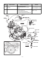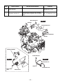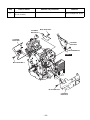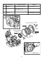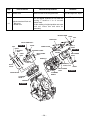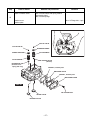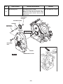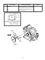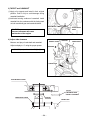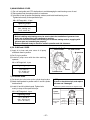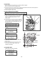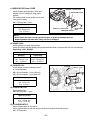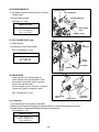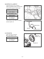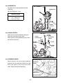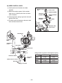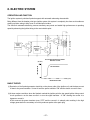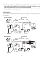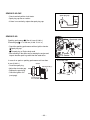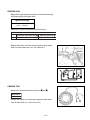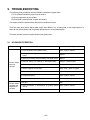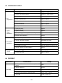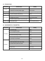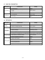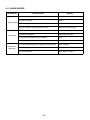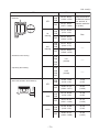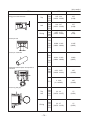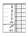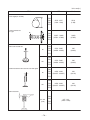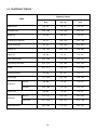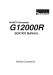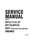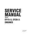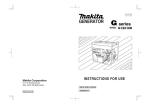
1
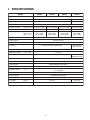
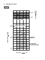
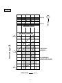
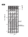
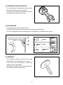
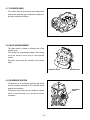
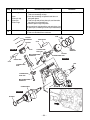
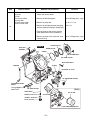
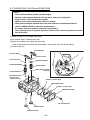
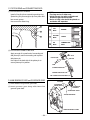
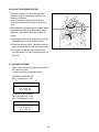
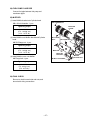
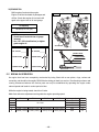
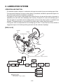
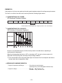
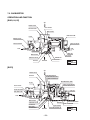
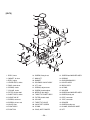
SERVICE
MANUAL
Models
EH63, 64, 65 and EH72
ENGINES
PUB-ES2158
Rev. 08/09
Robin America, Inc.
905 Telser Road • Lake Zurich, IL 60047 • Phone: 847-540-7300 • Fax: 847-438-5012
e-mail: [email protected] • www.subarupower.com
© Copyright 2009 Robin America, Inc.
CONTENTS
Section
Title
Page
1. SPECIFICATIONS . . . . . . . . . . . . . . . . . . . . . . . . . . . . . . . . . . . . . . . . . . . . . . . . . . 1
2. PERFORMANCE . . . . . . . . . . . . . . . . . . . . . . . . . . . . . . . . . . . . . . . . . . . . . . . . . . . 2
3. FEATURES . . . . . . . . . . . . . . . . . . . . . . . . . . . . . . . . . . . . . . . . . . . . . . . . . . . . . . . 7
4. GENERAL DESCRIPTION OF ENGINE COMPONENTS . . . . . . . . . . . . . . . . . . . 8
5. DISASSEMBLY AND REASSEMBLY
5-1 PREPARATIONS AND SUGGESTIONS . . . . . . . . . . . . . . . . . . . . . . . . . . . . . . . . . . . . 15
5-2 SPECIAL TOOLS . . . . . . . . . . . . . . . . . . . . . . . . . . . . . . . . . . . . . . . . . . . . . . . . . . . . . . 15
5-3 DISASSEMBLY PROCEDURES . . . . . . . . . . . . . . . . . . . . . . . . . . . . . . . . . . . . . . . . . . 16
5-4 REASSEMBLY PROCEDURES . . . . . . . . . . . . . . . . . . . . . . . . . . . . . . . . . . . . . . . . . . . 32
5-5 BREAK-IN OPERATION . . . . . . . . . . . . . . . . . . . . . . . . . . . . . . . . . . . . . . . . . . . . . . . . 48
6. LUBRICATION SYSTEM . . . . . . . . . . . . . . . . . . . . . . . . . . . . . . . . . . . . . . . . . . . . . 49
7. FUEL SYSTEM . . . . . . . . . . . . . . . . . . . . . . . . . . . . . . . . . . . . . . . . . . . . . . . . . . . . 52
8. ELECTRIC SYSTEM . . . . . . . . . . . . . . . . . . . . . . . . . . . . . . . . . . . . . . . . . . . . . . . . 57
9. TROUBLESHOOTING . . . . . . . . . . . . . . . . . . . . . . . . . . . . . . . . . . . . . . . . . . . . . . . 63
10. INSTALLATION . . . . . . . . . . . . . . . . . . . . . . . . . . . . . . . . . . . . . . . . . . . . . . . . . . . . 69
11. SERVICE DATA
11-1 STANDARD DIMENSIONS AND SERVICE LIMITS . . . . . . . . . . . . . . . . . . . . . . . . . . . 70
11-2 TIGHTENING TORQUE . . . . . . . . . . . . . . . . . . . . . . . . . . . . . . . . . . . . . . . . . . . . . . . . . 76
12. MAINTENANCE AND STORAGE
. . . . . . . . . . . . . . . . . . . . . . . . . . . . . . . . . . . . . 77
1. SPECIFICATIONS
MODEL
EH63D
Type
EH64D
EH65D
EH72D
Air-Cooled, 4-Stroke, V-Twin Cylinder, Horizontal P.T.O. shaft, OHV Gasoline Engine
Bore x stroke
mm (in.)
Displacement
cm3 (cu. in.)
2 - 80 x 65 (3.15 x 2.56)
2 - 84 x 65 (3.31 x 2.56)
653 (39.9)
720 (43.9)
8.3
Compression Ratio
Continuous Output
kW (HP) / r.p.m.
10.8 (14.5) / 3600
11.9 (16.0) / 3600
12.7 (17.0) / 3600
13.4 (18.0) / 3600
Maximum Output
kW (HP) / r.p.m.
13.4 (18.0) / 3600
15.3 (20.5) / 3600
16.4 (22.0) / 3600
18.6 (25.0) / 3600
Maximum Torque
N•m / r.p.m.
(kgf•m / r.p.m.)
(ft•lb. / r.p.m.)
43.3 / 2000
(4.41 / 2000)
(31.90 / 2000)
44.3 / 2200
(4.52 / 2200)
(32.69 / 2200)
45.6 / 2500
(4.65 / 2500)
(33.63 / 2500)
53.6 / 2500
(5.5 / 2500)
(39.78 / 2500)
Direction of Rotation
Counterclockwise as viewed from P.T.O. shaft side
Cooling System
Forced Air Cooling
Valve Arrangements
Overhead Valve (OHV)
Lubrication
Full pressure type (Trochoid Pump)
Lubricant
Capacity of Lubricant
Automotive Engine Oil SAE #20, #30 or 10W-30; Class SE or higher
1.55 (0.41)
L (U.S. gal.)
Carburetor
Down Draft, Float Type
Fuel
Automotive Unleaded Gasoline
Fuel Feed System
Diaphragm Pump (Pulse type)
Ignition System
Flywheel Magneto (Solid State)
Spark Plug
Charging Capacity
Down Draft, Float Type
(With Accel Pump)
NGK-BP6ES
12 - 15 (STD)
12 - 30 (Option)
V-A
Starting System
Electric Starter
Governor System
Centrifugal Flyweight Type
Air Cleaner
Dry Weight
Full pressure type
with oil Cooler
Double Element Type
kg (lb.)
Overall Length×Width×Height
44 (97.0)
317 x 477 x 475 (12.5 x 18.8 x 18.7)
mm (in.)
* Specifications are subject to change without notice.
–1–
46 (101.3)
2. PERFORMANCE
2-1 MAXIMUM OUTPUT
The maximum output is the output of an engine with its throttle valve fully opened under the condition that all
the moving parts are properly worn in after the initial break-in period.
A new engine may not produce full maximum output while its moving parts are still not broken-in.
NOTE :
Power curves shown in the following charts are made in conformity to SAE internal combustion engine
standard test code J1349
2-2 CONTINUOUS RATED OUTPUT
The continuous rated output is the output of an engine at optimum governed speed which is most favorable
from the view point of engine's life and fuel consumption.
When the engine is installed on a certain equipment, it is recommended that the continuous output required
from the engine be kept below this continuous rated output.
2-3 MAXIMUM TORQUE
The maximum torque is the torque at the output shaft when the engine is producing maximum output at
certain revolution.
–2–
2-4 PERFORMANCE CURVES
EH63D
35 (3.57)
MAXIMUM TORQUE
15
(20.1)
TORQUE
45 (4.59)
N-m
(kgf-m)
MAXIMUM HORSEPOWER
HORSEPOWER
kW
(HP)
10
(13.4)
CONTINUOUS
RATED HP
RECOMMENDED
HORSEPOWER RANGE
5
(6.7)
2000
2400
2800
3200
REVOLUTION
3600
r.p.m
–3–
EH64D
35 (3.57)
MAXIMUM TORQUE
TORQUE
45 (4.59)
N-m
(kgf-m)
MAXIMUM HORSEPOWER
15
(20.1)
HORSEPOWER
kW
(HP)
CONTINUOUS
RATED HP
10
(13.4)
RECOMMENDED
HORSEPOWER RANGE
5
(6.7)
2000
2400
2800
3200
REVOLUTION
3600
r.p.m
–4–
EH65D
35 (3.57)
MAXIMUM TORQUE
TORQUE
45 (4.59)
N-m
(kgf-m)
MAXIMUM HORSEPOWER
15
(20.1)
HORSEPOWER
kW
(HP)
CONTINUOUS
RATED HP
10
(13.4)
RECOMMENDED
HORSEPOWER RANGE
5
(6.7)
2000
2400
2800
3200
REVOLUTION
3600
r.p.m
–5–
EH72D
45 (4.59)
MAXIMUM TORQUE
20
(26.8)
TORQUE
55 (5.61)
N-m
(kgf-m)
MAXIMUM HORSEPOWER
HORSEPOWER
kW
(HP)
15
(20.1)
CONTINUOUS
RATED HP
10
(13.4)
RECOMMENDED
HORSEPOWER RANGE
5
(6.7)
2000
2400
2800
3200
REVOLUTION
–6–
3600
r.p.m
3. FEATURES
Highly rigid structure
●
High-carbon steel, forged crank shaft
●
Light-weight , tough alminum forged connectiong rod
●
Ball-bearing
●
Special cast iron cylinder liner
Long-lasting structure
●
Forced pressure lubrication of crankshaft by directly connected trochoid pump
●
Standard equipped oil cooler ensures a good lubrication environment
●
Ball bearing installed in the throttle bearing of the carbureter
Reliability
●
Unusually high dust proofing by a double compartment air cleaner and inner vent type carbureter
●
Carbureter equipped with acceleration pump, and receives excellent throttle response.
●
A fine distribution suction pipe and effective combustion chamber shape provide greater cubustion
stability and reduced gas emissions
Compact
●
Center height 133.3mm and 25HP
●
90°V2 cylinder built in crankcase
–7–
4. GENERAL DESCRIPTION OF ENGINE COMPONENTS
ROBIN EH63D/64D/65D/72D engine is air-cooled, 4-stroke, twin-cylinder, OHV arrangement gasoline engine.
The twin-cylinder is located in the angle of 90 degree; #1 cylinder is in the RH side and #2 cylinder in LH side
as viewed from flywheel (cooling fan) side.
4-1 CYLINDER AND CRANKCASE
The twin-cylinder and crankcase is single piece
aluminum die-casting.
The cylinder liner, made of special cast iron, is
molded into the aluminum casting.
The crankcase has a mounting surface on the output
shaft side, where the main bearing cover is attached.
4-2 MAIN BEARING COVER
The main bearing cover is an aluminum die-casting,
which is mounted on the output shaft side of the
crankcase.
Pilots and bosses are machined on the cover for
direct mounting of the engine onto such machines as
generators and pumps.
It is easy to inspect inside of the engine, after
removing the main bearing cover.
4-3 CRANKSHAFT
The crankshaft is forged carbon steel, and the crank
pin is induction-hardened.
The output end of the shaft has a crankshaft gear
pressed into position.
Engine oil passages are provided onto the journal
and pin portions of crankshaft for lubrication.
–8–
4-4 CONNECTING ROD AND PISTON
The connecting rod is forged aluminum alloy, and its
large and small ends function as bearings.
The piston is an aluminum alloy casting, and carries
two compression rings and one oil ring.
4-5 PISTON RINGS
The piston rings are made of special cast iron.
The profile of the top ring is barrel face and the second ring has a tapered face.
The oil ring is designed for better sealing and less oil consumption, in combination with 3 pieces.
1
1
TOP
RING
BARREL
2
SECOND
RING
TAPER
3
OIL
RING
COMBINATION
RING
2
3
4-6 CAMSHAFT
The camshaft is made of special cast iron and
camshaft gears are casted together in one piece.
Each 2 cam robs are provided for intake and
exhaust valves correspondingly.
Both sides of the shaft fit into the plane bearings on
the crankcase and main bearing cover.
–9–
4-7 CYLINDER HEAD
The cylinder head is an aluminum die-casting which
utilizes semi-spherical type combustion chamber for
the high combustion efficiency.
4-8 VALVE ARRANGEMENT
The intake valve is located on flywheel side of the
cylinder head.
The cooling fins and passages design lead cooling
air to the exhaust valve area for the optimum
cooling.
Hard alloy valve seats are molded in the cylinder
head.
EXHAUST VALVE
INTAKE VALVE
4-9 GOVERNOR SYSTEM
The governor is a centrifugal flyweight type which
ensures constant operation at the selected speed
against load variations.
The governor gear with governor weights is installed
inside of main bearing cover and driven by the
crankshaft.
– 10 –
GOVERNOR
GEAR
4-10 COOLING SYSTEM
The large fins on the flywheel provide sufficient
cooling air capacity for cylinder and cylinder head.
The cylinder baffle helps the cooling air flow
efficiently.
4-11 LUBRICATION SYSTEM
The engine is furnished with full pressure lubrication
system.
The trochoid type oil pump is driven by crankshaft
and delivers pressurized engine oil through the fullflow type oil filter to the journal and pin portions of
crankshaft and camshaft.
4-12 IGNITION SYSTEM
IGNITION COIL
The ignition system is a transistor controlled
magneto ignition system which consists of a flywheel
and an ignition coil with a built-in transistor installed
onto the crankcase.
FLYWHEEL
4-13 CHARGING SYSTEM
Multipolar charging coil is provided inside of flywheel. Charging capacity is 12V-15A or 12V-30A.
(12V-15A)
(12V-30A)
CABLE, EXTENDED
REGULATOR
REGULATOR
CHARGE COIL
CHARGE COIL
– 11 –
4-14 CARBURETOR
The engine is equipped with a down draft carburetor
that has a float controlled fuel system and a fixed
main jet.
The carburetors are calibrated carefully for the sure
FUEL CUT
SOLENOID VALVE
starting, low fuel consumption and sufficient output.
Fuel cut solenoid valve is provided to prevent engine
running on when the key switch is turned to off.
Accelerator-pump is provided for obtaining quick and
ACCELERATOR-PUMP
good throttle response. (EH72D)
4-15 AIR CLEANER
CLEANER COVER
WING NUT
The air-cleaner is a heavy-duty type with a dual
element system ; primary side is urethane foam
(half-wet) and secondary side is dry type.
ELEMENT
URETHANE FOAM
4-16 FUEL PUMP
The engine is equipped with a diaphragm type fuel
pump which is operated by the crankcase inside
vacuum pressure.
FUEL PUMP
– 12 –
4-17 SECTIONAL VIEW OF ENGINE
CARBURETOR
INTAKE MANIFOLD
IGNITION COIL
P.T.O.SHAFT
OIL PUMP
MAIN BEARING COVER
FLYWHEEL
OIL PUMP FILTER
– 13 –
CAMSHAFT
AIR CLEANER
GOVERNOR LEVER
PUSH ROD
ROCKER ARM
INTAKE AND
EXHAUST VALVES
SPARK PLUG
PISTON RING
PISTON
PISTON PIN
TAPPET
OIL COOLER
(EH72D)
OIL FILTER
ELECTRIC STARTER
CRANKCASE
CRANKSHAFT
– 14 –
CONNECTING ROD
5. DISASSEMBLY AND REASSEMBLY
5-1 PREPARATIONS AND SUGGESTIONS
When disassembling the engine, memorize the locations of individual parts so that they can be reassembled
correctly. If you are uncertain of identifying some parts, it is suggested that tags be attached to them.
Have boxes ready to keep disassembled parts by group.
To prevent losing and misplacing, temporarily assemble each group of disassembled parts.
Carefully handle disassembled parts, and clean them with washing oil if necessary.
Use the correct tools in the correct way.
When disconnecting electric wirings, be sure to hold and disconnect the connector housing.
5-2 SPECIAL TOOLS
No Special Tool is needed for disassembling and reassembling the engine.
For pulling off the flywheel, universal type puller being popular in the market place as shown in the illustration
is needed.
Tool No.
Tool
Use
228-95001-17
Flywheel puller with bolt
EH63,64,65,72 / DY30,35,41,42
FLYWHEEL PULLER
– 15 –
5-3 DISASSEMBLY PROCEDURES
Step
Parts to remove
Remarks and procedures
Fasteners
Drain engine oil by removing plugs located
on both side of crankcase.
1
Engine oil drain
2
Muffler cover
M6 x 14 Flange bolt : 4 pcs.
M6 x 8 Flange bolt : 2 pcs.
3
Muffler
M8 SUS Flange nut : 4pcs.
4
Muffler bracket
M8 x 20 bolt and
washer : 2pcs.
M6 FLANGE
BOLT
M14 x 12 Drain plug : 2 pcs.
OIL FILLER CAP
STEP 2
OIL LEVEL GAUGE
MUFFLER
COVER
M6 FLANGE
BOLT
M6 FLANGE BOLT
A
MUFFLER
STEP 3
GASKET
MUFFLER
BLACKET
M8 SUS FLANGE NUT
GASKET
A
M8 BOLT & WASHER
STEP 4
– 16 –
OIL DRAIN PLUG
(ON BOTH SIDE)
STEP 1
Step
Parts to remove
Remarks and procedures
Fasteners
5
Air cleaner cover and elements
Remove cleaner cover and cleaner element.
6
Air cleaner base
Remove breather pipe from #1 cylinder head. M6 x 12 Flange bolt : 3 pcs.
WING NUT
CLEANER
COVER
BREATHER PIPE
STEP 5
M6 FLANGE BOLT
CLEANER
ELEMENT
STEP 6
CLEANER BASE
HOSE CLAMP
BREATHER PIPE
HOSE CLAMP
– 17 –
Step
Parts to remove
Remarks and procedures
Fasteners
7
Blower housing
Control box
Disconnect fuel pipe and remove blower M6 x 18 Flange bolt : 2 pcs.
housing along with control box.
M6 x 14 Flange bolt : 6 pcs.
8
Chock control lever and link
(1) Remove the choke knob.
(2) Remove the choke contol link.
M6 bolt : 1 pc.
CONTROL BOX
LINK PIVOT
WAVED
WASHER
CHOKE
CONTROL ROD
BLOWER HOUSING
M5 TAPPING
SCREW
CLAMP
RETURN
SPRING
STEP 8
CHOKE
CONTROL
LINK
CHOKE
KNOB
M6 FLANGE
BOLT
STEP 7
M6 FLANGE BOLT
– 18 –
Step
Parts to remove
Carburetor
Remarks and procedures
Fasteners
M8 x 80 Flange bolt : 2 pcs.
At first remove fuel pipe.
Take out carburetor along with governor rod
and rod spring.
9
M8 FLANGE BOLT
CARBURETOR
FUEL PIPE
STEP 9
GASKET,
carburetor
– 19 –
Step
Parts to remove
Remarks and procedures
Governor lever
1. Remove bolt and take out lever.
(Make sure the fitting location of governor
springs.)
2. Disassemble in the following order.
(1) Governor spring
(2) Self lock nut
(3) Stop plate
(4) Spring washer
(5) Friction washer
(6) Speed control lever
Speed control lever
10
11
Speed control bracket unit
12
Starting motor
Fasteners
M6 x 12 bolt and
washer : 3 pcs.
M6 self-lock nut : 1 pc.
M6 x 12 Flange bolt : 2 pcs.
At first remove wiring.
M8 x 65 Flange bolt : 2 pcs.
M6 SELF LOCK
NUT
GOVERNOR
ROD
ROD
SPRING
STEP 10
M6 NUT
STOP PLATE
SPRING WASHER
FRICTION
WASHER
M6 BOLT
AND WASHER
SPEED CONTROL
LEVER
GOVERNOR
SPRING
SPACER
GOVERNOR
LEVER
FRICTION
WASHER
M6 FLANGE
BOLT
M8 FLANGE
BOLT
STEP 11
BRACKET UNIT,
speed control
STARTING MOTOR
STEP 12
– 20 –
Step
13
Parts to remove
Fuel pump
Ignition coil
14
Remarks and procedures
Remove pluse pipe at first.
Remove fuel pump ASSY and detach
bracket.
(1) Take out plug cap.
(2) Remove ignition coil.
(3) Cut out stop wire fixing bands.
(4) Disconnect stop wires from ignition coil.
Fasteners
M6 x 12 Flange bolt : 2 pcs.
M6 x 12 Flange bolt : 2 pcs.
M6 x 25 bolt &
washer : 4 pcs.
IGNITION
COIL
PLUG
TERMINAL
M6 BOLT AND
WASHER ASSY
SPARK
PLUG CAP
M6 BOLT AND
WASHER ASSY
TO KEY SWITCH
STEP 14
IGNITION
COIL
PLUG TERMINAL
SPARK PLUG CAP
HOSE CLAMP
FUEL PIPE
M6 FLANGE BOLT
M6 FLANGE
BOLT
BRACKET,
fuel pump
FUEL PUMP and
FUEL FILTER ASSY
IGNITION COIL
HOSE CLAMP
HOSE CLAMP
PULSE PIPE
STEP 13
– 21 –
FUEL FILTER
Step
Parts to remove
15
Intake manifold
16
Regulator and Wire CP
Remarks and procedures
Fasteners
M8 flange nut : 4 pcs.
Disconnect wire connector from regulator,
and then remove regulator from #1 cylinder
baffle.
M8 FLANGE NUT
M6 x 12 Flange bolt : 2 pcs.
STEP 15
GASKET
INTAKE MANIFOLD
M8 FLANGE NUT
GASKET
WIRING HARNESS
TO KEY SWITCH
STEP 16
STEP 16
TO IGNITION COIL
WIRE CP
TO IGNITION COIL
M6 FLANGE
BOLT
REGULATOR
– 22 –
Step
17
Parts to remove
Remarks and procedures
Cylinder baffles
(#1, #2, #3 & #4)
Fasteners
M6 x 12 flange bolt : 8 pcs.
CYLINDER
BAFFLE #3
M6 FLANGE BOLT
CYLINDER
BAFFLE #1
CYLINDER
BAFFLE #4
M6 FLANGE BOLT
STEP 17
M6 FLANGE BOLT
M6 FLANGE BOLT
CYLINDER
BAFFLE #2
– 23 –
Step
18
Parts to remove
Fasteners
Cooling fan
Remove cooling fan from flywheel.
M6 x 16 bolt & washer : 4 pcs.
Flywheel
Untighten flywheel nut and leave it to
avoid the flywheel fell out.
Take out flywheel by means of flywheel
puller.
M18 Flange nut: 1 pc.
19
20
Remarks and procedures
M5 x 20 bolt & washer : 4 pcs.(15A coil)
M5 x 25 bolt & washer : 4 pcs.(30A coil)
Charge coil
M18 NUT
M6 BOLT AND WASHER
STEP 19
WASHER
M5 BOLT AND WASHER
CHARGE COIL
STEP 18
STEP 20
COOLING FAN
FLYWHEEL
RING GEAR
FLYWHEEL PULLER
– 24 –
Step
Parts to remove
Remarks and procedures
Fasteners
21
Spark plug
Take care the spark plug is hot just after
stopping engine.
22
Oil cooler (EH72)
1. Disconnect oil hoses with clamps detached.
M6 x 12 Flange bolt : 4 pcs.
2. Remove oil cooler.
3. Remove bracket unit.
NGK : BPR4EY
STEP 21
SPARK PLUG
STEP 21
BRACKET UNIT
SPARK PLUG
M6 FLANGE BOLT
OIL COOLER
STEP 22
A
M6 FLANGE
BOLT
A
HOUSE
CLAMP
HOUSE CLAMP
OIL HOUSE#2
HOUSE CLAMP
– 25 –
OIL HOUSE#1
Step
23
24
Parts to remove
Remarks and procedures
Fasteners
Rocker cover
Remove rocker cover along with hook.
Cylinder head and Push rod
1. Bolt, pivot
2. Rocker arm
When removing “rocker arm” and “Bolt,pivot”, M10 x 65 Flange bolt : 8 pcs.
turn and adjust flywheel at TDC with the
marking “T” faced to “1” or “2” on each
cylinder head.
Put the marking of original position onto each
push rod, rocker arm and valve for
reassembly.
M6 x 28 Flange bolt : 8 pcs.
ROCKER ARM
PIVOT
NUT
PUSH ROD
M6 FLANGE BOLT
NUT
STEP 23
HOOK
PIVOT
ROCKER
ARM
PUSH
ROD
BOLT,
PIVOT
GUIDE PLATE
ROCKER COVER
M10 FLANGE
BOLT
STEP 23
ROCKER
COVER
M6 FLANGE
BOLT
GASKET 2
GASKET,
rocker cover
GASKET,
rocker cover
BOLT,
PIVOT
HOOK
M10 FLANGE
BOLT
GUIDE PLATE
CYLINDER
HEAD 2
CYLINDER
HEAD 1
GASKET 1
STEP 24
– 26 –
STEP 24
Step
Parts to remove
Intake & exhaust valves
25
Remarks and procedures
Fasteners
Take out collet-valves with spring retainer
depressed by hand.
Take out valve springs.
Breather cover
Breather plate
M6 x 14 Flange bolt : 2 pcs.
COLLET-VALVE
COLLET-VALVE
SPRING RETAINER
SPRING RETAINER
VALVE SPRING
VALVE SPRING
SEAL-INTAKE VALVE
(BLACK)
RETAINER PLATE
(Exhaust valve
spring side only)
GASKET , breather plate
BREATHER PLATE
GASKET , breather plate
BREATHER COVER
STEP 25
M6 FLANGE BOLT
INTAKE VALVE
EXHAUST VALVE
– 27 –
Step
Parts to remove
Remarks and procedures
Take out key from PTO shaft.
M8 x 45 Flange bolt : 10 pcs.
Wrap PTO shaft with polyvinyl tape not to
damage oil seal by key groove edge.
Tapping with plastic hummer, take out main
bearing cover.
Main bearing cover
26
GOVERNOR
SLEEEVE
GOVERNOR GEAR
WASHER
GOVERNOR
GEAR SHAFT
THRUST
BEARING
Wrap PTO shaft
with polyvinyl tape
M8 FLANGE
BOLT
GASKET
STEP 26
Fasteners
MAIN BEARING COVER
– 28 –
Step
27
Parts to remove
Remarks and procedures
Camshaft
Mate the markings both on crankshaft gear
and camshaft gear and then take out camshaft.
tappet
Put the marking of original position onto each
tappet for reassembly.
CAMSHAFT
TAPPET
STEP 27
TAPPET
CAMSHAFT
– 29 –
Fasteners
Step
Parts to remove
Connecting rod
Piston
*Piston pin clip
*Piston pin
*Piston rings
28
Crankshaft
29
Remarks and procedures
Fasteners
(1) Remove connecting rod bolts.
M8 Connecting rod bolt : 4 pcs.
Take out connecting rod cap.
(2) Push the connecting rod upwards and take out
along with piston.
(3) Take out clip and pull out piston pin, and then take
out piston from connecting rod.
(4) Remove piston rings from piston.
Put the marking of original position onto each piston, ring,
clip, piston pin, connecting rod and cap for reassembly.
(1) Remove key from crankshaft.
(2) Take out crankshaft from crankcase.
PISTON
RING SET
PISTON
CLIP
STEP 28
CLIP
PISTON PIN
CLIP
PISTON
RING SET
CONNECTING
ROD CAP
PISTON
M8 CONNECTING
ROD BOLT
CONNECTING ROD
STEP 28
PISTON PIN
CLIP
KEY
CONNECTING
ROD
CONNECTING
ROD CAP
M8 CONNECTING
ROD BOLT
CRANKSHAFT
STEP 29
SPACER
– 30 –
Step
Parts to remove
Crankcase
*Oil pump
*Oil filter
*Oil pressure switch
*Oil pump filetr
*Oil relief spring & ball
*Governor lever shaft
30
Remarks and procedures
Fasteners
(1) Disconnect wire connector from oil pressure
switch, and remove switch.
(2) Remove oil filter and adapter.
M6 x 28 Flange bolt : 3 pcs.
(3) Remove oil pump filter.
10-32 x 11: 1 pc.
(4) Remove oil relief plug and take out spring
and ball. (Make sure spring is jumped out.)
M14 x 12
(5) Take out snap pin and pull out governor
shaft. (Make sure not to loose washer.)
(6) Remove oil pump cover, outer rotor, inner
rotor and o-ring.
OUTER ROTOR
STEP 30
SNAP PIN
M6 x 14 Flange bolt : 4 pcs.
INNER ROTOR
WASHER
O RING
M6 FLANGE BOLT
OIL PUMP COVER
M6 FLANGE BOLT
O RING
WASHER
ADAPTER, oil cooler
OIL PRESSURE SWITCH
GOVERNOR LEVER
SHAFT
10-32 FLANGE
BOLT (Inch)
OIL PUMP FILTER
[EH65]
STEEL BALL
SPRING, relief valve
OIL FILTER
OIL FILTER
GASKET, aluminum
PLUG, oil relief
OIL PRESSURE SWITCH
– 31 –
5-4 REASSEMBLY PROCEDURES
5-4-1 PRECAUTIONS FOR REASSEMBLY
1) Clean parts thoroughly before reassembly.
Pay most attention to cleanliness of piston, cylinder, crankshaft, connecting rod and bearings.
2) Scrape off all carbon deposits from cylinder head, piston top and piston ring grooves.
3) Check lip of oil seals. Replace oil seal if the lip is damaged. Apply oil to the lip before reassembly.
4) Replace all the gaskets with new ones.
5) Replace keys, pins, bolts, nuts, etc., if necessary.
6) Torque bolts and nuts to specification referring to the "TORQUE SPECIFICATIONS".
7) Apply oil to rotating and sliding portions.
8) Check and adjust clearances and end plays where specified in this manual.
9) When there are many bolts, fasten opposing bolts
(Do not fasten bolts in a circular order. In other words, after tightening one place, go to the opposite side
and tighten this place next.)
5-4-2 Pre-assembly
A. CRANKCASE
(1) Fix oil pump filter in position.
(2) Insert ball and spring into the oil relief valve hole and tighten plug to the specified torque.
Tightening torque
14.7 - 24.5 N・m
(150 - 250 kgf・cm)
(10.8 - 18.0 ft・lb.)
(3) Fit governor lever shaft with clip.
(4) Tighten oil drain plugs on both side of crankcase.
SNAP PIN
WASHER
OIL DRAIN PULG
WASHER
O RING
GASKET
GOVERNOR
LEVER SHAFT
ADAPTER,
oil cooler
GASKET
OIL DRAIN
PULG
10-32 FLANGE
BOLT (Inch)
M6 FLANGE BOLT
OIL PUMP
FILTER
STEEL BALL
SPRING, relief valve
PLUG, oil relief
GASKET,
aluminum
– 32 –
B. CYLINDER HEAD, VALVES and ROCKER ARM
NOTE ;
* Clean valves and wash cylinder head thoroughly.
* Remove carbon and gum deposits from the valves, seats, ports and guides.
* Inspect valves, valve seats and valve guides.
* Replace valves that are badly burned, pitted or warped.
* Valve guides should be replaced when valve stem clearance exceeds specifications.
(Refer to SERVICE DATA for clearance specifications. )
If exceeds, draw valve guides out and press new guides in.
After replacing valves and guides, lap valves in place until a uniform ring shows around the
face of the valve.
(1) Attach oil seal only onto intake valve guide.
(2) Set retainer plate on exhaust valve side.
(3) Apply oil to washer, valve spring and valve stem.
Place cylinder head on flat table and install washer, valve spring, valve and spring retainer.
(4) Install rocker arm.
ROCKER ARM
ROCKER ARM
COLLET-VALVE
COLLET-VALVE
SPRING RETAINER
VALVE SPRING
SPRING RETAINER
VALVE SPRING
SEAL-INTAKE VALVE
(BLACK)
RETAINER PLATE
(Exhaust valve
spring side only)
GASKET , breather plate
BREATHER PLATE
GASKET , breather plate
BREATHER COVER
M6 FLANGE BOLT
INTAKE VALVE
EXHAUST VALVE
– 33 –
C. PISTON RING and CONNECTING ROD
(1) PISTON and PISTON RING
Install oil ring first, then second ring and top ring.
Spread ring only far enough to slip over piston and
into correct groove.
Use care not to distort ring.
NOTE ;
* Top ring can be fit either way.
* Install second ring with punched mark
beside the gap on the top side.
* As for oil ring, rails should be placed on
and below the expander.
1
1
TOP
RING
BARREL
2
SECOND
RING
TAPER
3
OIL
RING
COMBINATION
RING
2
3
(2) PISTON and CONNECTING ROD
PISTONRING SET
Apply enough oil to small end of connecting rod
CLIP
and piston pin, and fix connecting rod to piston
PISTON PIN
with piston pin.
PISTON
Use clips on the both side of the piston pin to
secure piston pin in position.
CLIP
CONNECTING ROD
CONNECTING ROD CAP
M8 CONNECTING ROD BOLT
D. MAIN BEARING COVER and GOVERNOR GEAR
WASHER
(1) Insert washer into governor gear shaft.
(2) Insert governor gear along with sleeve into
governor gear shaft.
GOVERNOR
GEAR SHAFT
GOVERNOR
SLEEEVE
GOVERNOR GEAR
THRUST BEARING
MAIN BEARING COVER
– 34 –
5-4-3 Re-assembly
CRANKSHAFT
1) CRANKSHAFT
Install crankshaft onto crankcase.
NOTE ;
* Apply enough oil to bearing portion of
crankcase.
* For smooth fitting of crankshaft, assemble
oil pump related parts later.
* For easy installation, put crankcase on box
or wood blocks.
2) PISTON and CONNECTING ROD
NOTE ;
* The "1" mark of the connecting rod for #1
cylinder and "2" mark for #2 cylinder
should be faced to the PTO side when
assembled.
* Apply enough oil to piston rings,
connecting rod bearings (large end) and
cylinder bore before assembly.
* Set gaps of piston rings as shown in
the illustration.
(2) Temporary fit key and flywheel and turn crankshaft
to BTDC (bottom dead center). Lightly tap the top
of piston until large end of the rod meet the pin
portion of crankshaft.
(3) Set connecting rod cap to connecting rod with the
alignment marks mated and the clinching portion
clinched. Tighten bolts to the specified torque.
PISTON RING COMPRESSOR
CONNECTING ROD
1
(1) Install piston and connecting rod assembly into
cylinder by using a piston ring compressor to hold
piston rings.
MARK "1"
TOP RING
SECOND RING
OIL RING
M8 Connecting rod bolt : 4 pcs.
Tightening torque
ALIGNMENT MARKS
22.0 - 27.0 N・m
(225 - 275 kgf・cm)
(16.3 - 19.8 ft・lb.)
NOTE ;
* When depressing connecting rod, make
sure not to damage another connecting rod.
* Check for free movement of piston and
connecting rod by turning crankshaft
slowly.
– 35 –
3) TAPPET and CAMSHAFT
CAMSHAFT
GEAR
(1) Apply oil to tappets and install in their original
position. Push in fully to avoid damage during
camshaft installation.
(2) Lubricate bearing surfaces of camshaft. Install
camshaft into the crankcase with the timing mark
on both crankshaft gear and camshaft alined.
TIMING MARK
CRANKSHAFT
GEAR
CAUTION:
Incorrect alinement will cause
malfunction of the engine.
4) Adjust side clearance
HEIGHT GAUGE
Measure end play of crankshaft and camshaft.
READING 2
CRANKSHAFT
Adjust end play to “0” using the proper spacer.
READING 1
SPACER (mm) = “A” + 0.48 - “B” (① - ②)
CRANKCASE
MAIN BEARING COVER
A
CRANKSHAFT GEAR
0.48 mm
(THICKNESS WITH
GASKET TIGHTENED)
SPACER
CRANKCASE
B
– 36 –
5) MAIN BEARING COVER
(1) Put a oil seal guide onto PTO shaft portion to avoid damaging the main bearing cover oil seal.
(2) Place gasket onto the mating surface of crankcase.
(3) Lubricate oil seal lip portion and bearing surfaces, and install main bearing cover.
Tighten bolts evenly to the specified torque.
M8 x 45 Flange bolt : 10 pcs.
Tightening torque
22.5 - 27.5 N・m
(230 - 280 kgf・cm)
(16.5 - 20.2 ft・lb.)
NOTE ;
* Before installing main bearing cover, be sure to check the installation of governor lever
shaft and oil pump filter in the crankcase in position.
* Tap cover with a soft hammer until tacthing the crankcase mating surface, engaging with
governor gear and camshaft gear properly.
* Rotate crankshaft slowly to check for smooth operation and side clearance.
6) OIL PUMP and COVER
(1) Apply oil to inner and outer rotors of oil pump
and attach them in position.
(2) Set O-ring in position.
(3) Install oil pump cover with the allow marking
upwards.
INNER ROTOR
OIL PUMP COVER
"
"MARKING
M6 x 18 Flange bolt : 4 pcs.
Tightening torque
6.8 - 8.8 N・m
(70 - 90 kgf・cm)
(5.1 - 6.5 ft・lb.)
O-RING
OUTER ROTOR
7) CYLINDER HEAD
(1) Set dowel pins in the holes on the cylinder head surface.
(2) Attach head gaskets in position onto #1 and #2 cylinder
head surfaces.
NOTE :
Be sure to check dowel pin, and replace
with new one if damaged.
(3) Install #1 and #2 cylinder heads. Tighten bolts
evenly in steps to the specified torque.
Tighten the cylinder head bolts in diagonal order.
Tightning Torque
M10 x 65 Flange bolt : 4 pcs.
Cylinder
head bolts
Tightening torque
41.0 - 49.0 N・m
(400 - 500 kgf・cm)
(30.2 - 36.1 ft・lb.)
1
4
3
2
1st step
2nd step
Final step
M10 x 65 mm
25 N・m
35 N・m
45 N・m
Flange bolt (255 kgf・cm) (357 kgf・cm) (459 kgf・cm)
: 4 pcs.
(18.4 ft・lb.) (25.8 ft・lb.)
(33.2 ft・lb.)
– 37 –
8) PUSH RODS
Rotate crankshaft to the position in the no lifted condition of tappet.
Be sure to loose the rocker arm adjust screw.
(1) Insert push rods into the concave portion of tappet and set the other end to the concave portion of
rocker arm adjust screw with valve spring depressed.
(2) Temporally tighten adjust screw.
9) VALVE CLEARANCE ADJUSTMENT
NOTE ;
Temporally fit the flywheel in position for easy operation.
(1) Rotate crankshaft clockwise to the TDC (top dead
center) of compression stroke by matching the
mark "T" of flywheel with the mark "1" of #1
cylinder head.
(2) Loosen lock nut on rocker arm and turn adjusting
screw to adjust the clearance between rocker arm
and valve stem end, and then tighten lock nut to
the specified torque.
THICKNESS GAUGE
Valve Clearance (Cold condition)
0.07 - 0.13 mm (0.003 - 0.005 in.)
Lock nut
Tightening torque
6.8 - 8.8 N・m
(70 - 90 kgf・cm)
(5.0 - 6.5 ft・lb.)
Pivot bolt
Tightening torque
#1 CYLINDER
16.6 - 18.6 N・m
(170 - 190 kgf・cm)
(12.3 - 13.7 ft・lb.)
1
(3) Adjust valve clearance of #2 cylinder side in the
MARK"1"
same manner.
(4) Rotate crankshaft several times and be sure to
MARK" I "
check valve clearance again. Adjust valve
clearance if necessary.
FLYWHEEL
10) ROCKER COVER
Install rocker cover with new gasket.
M6 x 28 Flange bolt : 8 pcs.
Tightening torque
6.8 - 8.8 N・m
(70 - 90 kgf・cm)
(5.0 - 6.5 ft・lb.)
– 38 –
11) BREATHER PIPE and COVER
GASKET , breather plate
Attach breather plate (breather valve) and
breather cover to crankcase using proper
gaskets.
Put breather plate in such position as its reed
valve opens outside.
BREATHER PLATE
M6 x 14 Flange bolt : 2 pcs.
Tightening torque
2.9 - 4.9 N・m
(30 - 50 kgf・cm)
(2.2 - 3.6 ft・lb.)
GASKET , breather plate
BREATHER COVER
M6 FLANGE
BOLT
NOTE ;
* Never tighten the bolts over the specified torque, or gasket is damaged and cut.
* Replace gaskets with new ones if they are torn or damaged.
12) SPARK PLUG
Install spark plug to each cylinder head.
Check the carbon and heat damage around electrode and clean or replace with new one as necessary.
Spark plug : NGK - BPR4EY
Tightening torque
New plug
Current plug
11.7 - 14.7 N・m
(120 - 150 kgf・cm)
(8.6 - 10.8 ft・lb.)
22.1 - 26.9 N・m
(225 - 275 kgf・cm)
(16.3 - 19.8 ft・lb.)
13) CHARGE COIL
CHARGE COIL
Install charge coil with the wiring located
at 2-o’clock position.
PULLING
M8 FLANGE
BOLT : 2 pcs.
M5 x 20 bolt & washer : 4 pcs.(15A coil)
M5 x 25 bolt & washer : 4 pcs.(30A coil)
Tightening torque
2.9 - 3.9 N・m
(30 - 40 kgf・cm)
(2.2 - 2.9 ft・lb.)
14) STARTER MOTOR
Install starter motor.
M8 x 65 Flange bolt : 2 pcs.
ELECTRIC
STARTER
Tightening torque
16.6 - 18.6 N・m
(170 - 190 kgf・cm)
(12.3 - 13.7 ft・lb.)
15) CYLINDER BAFFLE
Attach cylinder baffle #1, #2 and #3.
Attach cylinder baffle #4 with the charge coil harness retracted in the dent portion.
M6 x 12 Flange bolt
– 39 –
16) INTAKE MANIFOLD
GASKET, muffler
(1) Set gasket (stainless steel) onto both #1 and #2
cylinder head.
M8 FLANGE NUT
(2) Install intake manifold.
INTAKE MANIFOLD
M8 flange nut : 4 pcs.
Tightening torque
16.6 - 18.6 N・m
(170 - 190 kgf・cm)
(12.3 - 13.7 ft・lb.)
M8 FLANGE
NUT
GASKET, muffler
17) OIL COOLER (EH72 only)
BRACKET UNIT
(1) Attach bracket.
M6 FLANGE
BOLT
OIL
COOLER
(2) Assemble oil cooler onto bracket.
M6 x 12 Flange bolt : 4 pcs.
Tightening torque
6.8 - 8.8 N・m
(70 - 90 kgf・cm)
(5.0 - 6.5 ft・lb.)
HOSE
CLAMP
HOSE#1
HOSE#2
18) REGULATOR
Install regurator onto cylinder baffle #1.
Install regulator onto cylinder baffle #1 with
the terminal of earth wire (white) commonly
fixed on the right-hand side.
Connect charge coil wire connector to regulator.
Connect wire (green) to magnetic switch.
M6 x 18 Flange bolt : 2 pcs.
M6 FLANGE
BOLT
REGULATOR
CYLINDER
BAFFLE #1
19) FLYWHEEL
(1) Put woodruff key in the keyway of crankshaft.
(2) Wipe off oil and grease thoroughly from tapered portion of crankshaft and flywheel center hole.
(3) Install flywheel to crankshaft and tighten flywheel nut with washer.
M18 flange nut : 1 pc.
Tightening torque
100 - 120 N・m
(1020 - 1220 kgf・cm)
(73.8 - 88.5 ft・lb.)
– 40 –
20) IGNITION COIL and WIRE CP
Temporally fit ignition coil to crankcase.
THICKNESS GAUGE
IGNITION COIL
Adjust air gap between ignition coil and flywheel
using a thickness gauge and tighten bolts.
Ignition coil air gap
WIRE
0.3 - 0.5 mm
(0.012 - 0.020 in.)
M6 x 30 bolt & washer : 4 pcs.
Tightening torque
6.8 - 8.8 N・m
(70 - 90 kgf・cm)
(5.1 - 6.5 ft・lb.)
Connect wiring from key switch to the primary
terminal of ignition coil.
TO KEY SWITCH
TO IGNITION COIL #1
WIRE CP
TO IGNITION COIL #2
21) COOLING FAN
Attach cooling fan onto flywheel.
M6 x 16 bolt & washer : 4 pcs.
M6 BOLT and
WASHER : 4 pcs.
Tightening torque
6.8 - 8.8 N・m
(70 - 90 kgf・cm)
(5.1 - 6.5 ft・lb.)
COOLING FAN
– 41 –
22) CARBURETOR
M8 FLANGEBOLT
Set gasket onto intake manifold and install
carburetor.
CARBURETOR
M8 x 80 Flange bolt : 2 pcs.
Tightening Torque
16.6 - 18.6 N・m
(170 - 190 kgf・cm)
(12.3 - 13.7 ft・lb.)
GASKET,
carburetor
23) CHOKE CONTROL
Attach chock control link between carburetor
chock lever and chock control lever.
Attach governor spring between governor lever
and speed control lever.
LINK PIVOT
WAVED
WASHER
CHOKE
CONTROL ROD
RETURN
SPRING
M5 TAPPING
SCREW
CLAMP
CHOKE
KNOB
CHOKE
CONTROL
LINK
24) GOVERNOR LEVER
GOVERNOR SHAFT
Attach governor rod and rod spring between
governor lever and carburetor throttle lever, and
GOVERNOR
LEVER
insert the governor lever to governor lever
shaft. Tighten locking bolt temporarily.
ROD SPRING
GOVERNOR ROD
– 42 –
THROTTLE LEVER
25) SPEED CONTROL LEVER
(1) Install speed control bracket onto intake
manifold.
M6 SELF LOCK
NUT
(2) Attach return spring, spacer, friction washer,
wing nut, etc. to speed control lever as shown
in the ilustration.
STOP PLATE
SPRING WASHER
FRICTION
WASHER
(3) Connect governor spring to governor lever and
speed control lever.
SPEED CONTROL
LEVER
FRICTION
WASHER
(4) Fit chock control link between carburetor chock
lever and chock control lever.
M6 FLANGE
BOLT
BRACKET UNIT,
speed control
CARBURETOR
GOVERNOR
GEAR
GOVERNOR
LEVER
b
ROD SPRING
a
5
4
3
2
1
GOVERNOR ROD
FULL CLOSE
FULL OPEN
A
B
LOCK NUT
Fitting location of governor rod and governor spring
50Hz
60Hz
EH63
A-3(b)
A-2(b)
EH64
A-3(b)
A-2(b)
EH65
A-3(a)
A-2(a)
EH72
A-5(a)
A-4(a)
GOVERNOR SPRING
ADJUSTING
SCREW
SPEED CONTROL LEVER
HIGH SPEED
LOW SPEED
– 43 –
26) ADJUST GOVERNOR SYSTEM
●
Governor system is centrifugal flyweight type.
Governor weight is installed into governor gear
driven by crankshaft.
Governor weight movement is transferred to
carburetor throttle lever via governor shaft and
lever.
●
Engine speed is maintained at the constant speed
by carburetor throttle valve opening and closing
operation in accordance with load condition of
engine.
GOVERNOR LEVER
(1) Push speed control lever all the way to the high
speed position and fix it by tightening nut.
(2) Check that governor lever is pulled by governor
spring and carburetor throttle valve is fully open.
(3) Turn governor shaft counterclockwise all the
way and tighten lock bolt to secure the lever on
the shaft.
27) BLOWER HOUSING
Attach blower housing to crankcase with control
box commonly fixed.
Connect fuel pipes onto blower housing.
BLOWER HOUSING(Front)
M6 x 14 Flange bolt : 4 pcs.
Tightening torque
3.9 - 5.9 N・m
(40 - 60 kgf・cm)
(2.9 - 4.3 ft・lb.)
BLOWER HOUSING(Side)
M6 x 18 Flange bolt : 2 pcs.
M6 x 14 Flange bolt : 2 pcs.
Tightening torque
2.9 - 4.9 N・m
(30 - 50 kgf・cm)
(2.2 - 3.6 ft・lb.)
– 44 –
GOVERNOR SHAFT
28) FUEL PUMP and FUEL PIPE
(1) Install fuel pump bracket onto #2 cylinder baffle.
FUEL PUMP BRACKET
M6 x 12 Flange bolt : 2 pcs.
Tightening torque
6.8 - 8.8 N・m
(70 - 90 kgf・cm)
(5.0 - 6.5 ft・lb.)
(2) Install fuel pump onto fuel pump bracket.
FUEL PUMP
FUEL PUMP
M6 x 12 Flange bolt : 2 pcs.
Tightening torque
4.5 - 5.5 N・m
(45 - 56 kgf・cm)
(3.3 - 4.1 ft・lb.)
(3) Connect fuel pipe between carburetor and fuel
pump.
29) AIR CLEANER and BREATHER PIPE
(1) Connect breather pipe to air cleaner base.
(2) Fit air cleaner base onto carburetor.
M6 x 12 Flange bolt : 3 pcs.
AIR CLEANER BASE
Tightening torque
6.8 - 8.8 N・m
(70 - 90 kgf・cm)
(5.0 - 6.5 ft・lb.)
(3) Connect breather pipe to #1 cylinder head.
(4) Set air cleaner element along with urethane
foam onto base.
(5) Install air cleaner cover with knob.
– 45 –
30) OIL PRESSURE SWITCH
●
Install oil pressure switch onto crankcase.
[EH63, 64, 65]
●
Install oil pressure switch onto adapter(Oil
cooler). [EH72]
[EH63, 64, 65]
OIL PRESSURE SWITCH
Tightening torque
5.9 - 9.8 N・m
(60 - 100 kgf・cm)
(4.3 - 7.2 ft・lb.)
[EH72]
NOTE ;
Not to tighten excessively.
OIL PRESSURE SWITCH
31) OIL FILTER
[EH63, 64, 65]
Apply oil to O-ring and install oil filter by tighte3/4 TURNS
ning about 3/4 turns after attaching crankcase
surface.
OIL FILTER
Tightening torque
9.9 - 14.7 N・m
(100 - 150 kgf・cm)
(16.3 - 19.8 ft・lb.)
[EH72]
NOTE ;
Start engine after assembling,
and check for no oil leakage
from oil filter.
3/4 TURNS
O RING
– 46 –
OIL FILTER
32) FUEL PUMP PLUSE PIPE
Connect fuel pipe between fuel pump and
crankcase nipple.
33) MUFFLER
(1) Install Muffler bracket onto Cylinder head.
M6 FLANGE BOLT
M8 x 20 bolt & washer : 2 pcs.
Tightening torque
MUFFLER
COVER
16.6 - 18.6 N・m
(170 - 190 kgf・cm)
(12.3 - 13.7 ft・lb.)
(2) Install Muffler onto Muffler bracket and Cylinder
head.
M6 FLANGE
M6 FLANGE BOLT
BOLT
M8 SUS flange nut : 4 pcs.
Tightening torque
A
16.6 - 18.6 N・m
(170 - 190 kgf・cm)
(12.3 - 13.7 ft・lb.)
MUFFLER
MUFFLER
BLACKET
(3) Install Muffler cover onto Muffler.
A
M6 Flange bolt : 6 pcs.
M8 BOLT & WASHER
Tightening torque
6.8 - 8.8 N・m
(70 - 90 kgf・cm)
(5.0 - 6.5 ft・lb.)
34) FINAL CHECK
Be sure to check loosen bolts and nuts, and
also electric wiring connections.
– 47 –
GASKET
M8 SUS
FLANGE NUT
35) ENGINE OIL
Refill engine oil and start the engine.
Standard
Option
Engine oil will be lubricated oil passages and
OIL GAUGE
oil filter. Check the engine oil level and refill
again to the upper level of oil level gauge.
Oil Capacity
1.55 liter (0.41 U.S. gal.)
NOTE ;
* Check the oil level with the oil gauge
inserted.
* Use “SE” (API classification) or higher
grade engine oil.
OIL GAUGE
OIL GAUGE
OIL GAUGE
UPPER LEVEL
UPPER LEVEL
UPPER LEVEL
LOWER LEVEL
LOWER LEVEL
LOWER LEVEL
5-5 BREAK-IN OPERATION
An engine that has been completely overhauled by being fitted with a new piston, rings, valves and
connecting rod should be thoroughly RUN-IN before being put back into service. Good bearing surfaces and
running clearances between the various parts can only be established by operating the engine under
reduced speed and loads for a short period of time.
While the engine is being tested, check for oil leaks.
Make final carburetor adjustment and regulate the engine operating speed.
EH63
EH64
EH65
EH72
Engine speed(rpm)
STEP
2500
1
3000
2
No Load
3600
3
5.4kW (7.3HP) 5.9kW (7.3HP) 6.3kW (8.5HP) 6.7kW (9.0HP)
3600
4
5
10.8kW (14.5HP) 11.9kW (14.5HP) 12.7kW (17.0HP) 13.4kW (18.0HP)
3600
– 48 –
Time
10
10
10
30
30
6. LUBRICATION SYSTEM
OPERATION AND FUNCTION
* Full lubrication system is adopted, in combination with large-size torchoid oil pump and cartridge type oil filter.
* The large-size trochoid type oil pump is driven directly by crankshaft, and delivers pressurized engine oil to
the journal and pin portions of crankshaft, camshaft etc.
* The engine oil in the oil pan is fed through the oil pump filter into oil pump and the engine oil pressure is
adjusted by the relief valve after discharging from oil pump. Through the oil cooler and cartridge type oil
filter, the engine oil is provided onto the rotating portions such as journal and pin portion of crankshaft and
camshaft. The splashed engine oil is provided to the cylinder, piston, cylinder head valve system.
* The by-pass valve is incorporated into the cartridge type oil filter. In case that the oil filter element is
clogged, the engine oil is fed through the by-pass valve into the crankcase oil passage.
[EH63, 64, 65]
OIL FILTER
CAMSHAFT
OIL PRESSURE SWITCH
CRANKSHAFT
OIL PUMP
RELIEF VALVE
OIL PUMP FILTER
Oil 1
relief
valve
Oil pan
Oil pump
filter
2
Oil
puressure
switch
Oil
pump
1
Oil relief Valve opening pressure : 3.8 kg/cm2 (373KPa)
Camshaft
journal
Element
Crankshaft
journal
(Flywheel side)
Crankpin &
Connecting rod
large end
Splash
Cylinder
Crankpin &
Connecting rod
small end
Cam & Tappet
2 Oil pressure switch
Normally close type
Contact pressure : 1.0kg/cm2 (98KPa)
Rocker arm &
Valve stem
– 49 –
Crankshaft
journal
(P.T.O. side)
[EH72]
OIL PRESSURE SWITCH
OIL COOLER
CAMSHAFT
OIL FILTER
CRANKSHAFT
RELIEF VALVE
OIL PUMP
OIL PUMP FILTER
Oil 1
relief
valve
Oil pan
Oil pump
filter
Oil
pump
2
Oil
puressure
switch
1
Oil relief Valve opening pressure : 3.8 kg/cm2 (373KPa)
Camshaft
journal
Oil
cooler
Element
Crankshaft
journal
(Flywheel side)
Crankpin &
Connecting rod
large end
Splash
Cylinder
Crankpin &
Connecting rod
small end
Cam & Tappet
2 Oil pressure switch
Normally close type
Contact pressure : 1.0kg/cm2 (98KPa)
Rocker arm &
Valve stem
– 50 –
Crankshaft
journal
(P.T.O. side)
ENGINE OIL
Using engine oil of the correct grade and viscosity greatly lengthens engine life and improves performance.
Too much or too little oil can also result in serious problems, including engine seizure.
●
CLASSIFICATION BY OIL GRADE
API (American Petroleum Institute)
Classification
SA
SB
SC
SD
SE
SF
SG
SH
SJ
Grades suited for Robin Engine: SE or higher (SG,SH or SJ in recomended)
●
CLASSIFICATION BY OIL VISCOSITY
SAE (Society of Automotive Engineers)
5W
10W
Single grade
20W
#20
#30
#40
Multigrade
10W-30
10W-40
Ambient
temperature
Be sure to use automobile engine oil of the viscosity shown in the table above, depending on
environmental air temperature.
When the air temperature falls below –20℃ or rises above 40℃, be sure to choose engine oil of
appropriate viscosity and grade, according to the prevailing conditions.
※ Care must be taken when using multi-grade engine oil, because the oil consumption rate tends to
increase when the air temperature is high.
●
ADDING AND CHANGING ENGINE OIL
○ Engine oil inspection and filling up . . . . . . . . . Every time you use the engine
(add engine oil up to the designated maximum level)
○ Engine oil change . . . . . . . . . . . . . . . . . . . . . .First time After 20 hours’ use
Thereafter Every 100 hours’ use
– 51 –
7. FUEL SYSTEM
7-1 FUEL PUMP
●
Fuel suction process
The inside of crankcase becomes vacuum condition in accordance with the piston moving upwards
to the top dead center.
The vacuum pressure, which is introduced via hose into the pulse chamber of fuel pump, pulls the
diaphragm, and then the inside of pump chamber becomes vacuum condition.
As the results, the suction valve is opened and fuel goes into pump chamber frown suction chamber.
Pump chamber
Pulse chamber
Suction chamber
Suction
●
Pulsing pressure
Fuel discharge process
The vacuum pressure of crankcase inside is decreased in accordance with the piston moving
downwards to the bottom dead center.
The vacuum pressure of the pulse chamber is also decreased and the diaphragm moved back by
means of the return spring force.
The fuel in the pump chamber is pressed by the diaphragm, and delivered to the discharge chamber
through the discharge valve.
Discharge
Pump chamber
Discharge chamber
Pulse chamber
Pulsing pressure
– 52 –
7-2. CARBURETOR
OPERATION AND FUNCTION
[EH63, 64, 65]
AIR
CHOKE VALVE
PILOT AIR JET
AIR VENT HOLE
MAIN AIR JET
EMULSION TUBE
FLOAT
NEEDLE VALVE
FUEL CUT VALVE
FUEL INLET PIPE
FUEL
MAIN JET
MAIN NOZZLE
PILOT JET
THROTTLE VALVE
BY-PASS
TAMPER CAP
MIXTURE
PILOT OUTLET
FUEL
AIR
MIXTURE
[EH72]
AIR
CHOKE VALVE
AIR VENT
SLOW AIR BLEED JET
ACCELERATION NOZZLE
MAIN AIR BLEED JET
MAIN EMULSION TUBE
FLOAT
CHECK VALVE SPRING
OUTLET CHECK VALVE
FLOAT VALVE
FLOAT VALVE SEAT
LEAK JET
FUEL INLET PIPE
FUEL
MAIN NOZZLE
SLOW JET
MAIN JET
THROTTLE VALVE
DIAPHRAGM SPRING
PUMP DIAPHRAGM
SLOW PORT
IDEL PORT
BACUUM PORT
IDEL SCREW
BACUUM CUSHION JET
MIXTURE
– 53 –
FUEL
AIR
MIXTURE
FLOAT SYSTEM
The float system is consists of a float and a needle valve, and maintains a constant fuel level during
engine operation.
The fuel flows from the fuel tank into the float chamber through needle valve.
When the fuel rises to a specific level, the float rises, and when its buoyancy and fuel pressure are
balanced, the needle valve closes to shut off the fuel, thereby keeping the fuel at the predetermined level.
Air vent hole of float chamber is provided around the carburetor air hone and the fuel vapor is sucked into
the combustion chamber. This closed system has unti-dust feature.
PILOT SYSTEM
The pilot system feeds the fuel to the engine during idling and low-speed operation.
The fuel is fed through the main jet to the pilot jet, where it is metered, and mixed with the air metered by
the pilot air jet.
The fuel-air mixture is fed to the engine through the pilot outlet and the by-pass.
At idling speed, the fuel is mainly fed from the pilot outlet.
MAIN SYSTEM
The main system feeds the fuel to the engine at medium-and high-speed operation.
The fuel is metered by the main jet and fed to the main nozzle. The air metered by the main air jet is
mixed with the fuel through the emulsion tube, and the mixture is atomized out of the main bore. It is
mixed again with the air taken through the air cleaner into an optimum fuel-air mixture, which is supplied to
the engine.
CHOKE
The choke is used for easy start when engine is cold.
When the starter is operated with a choke valve fully closed, the negative pressure applied to the main
nozzle increases and draws much fuel accordingly; thus easily start up the engine.
ACCELERATOR-PUMP SYSTEM (EH72 only)
When the throttle is opened rapidly for acceleration, air flow and manifold vacuum change almost
instantaneously. Because fuel is heavy and lags behind air flow, a momentary leanness results. The
accelerator-pump supplies extra fuel for smooth operation during this condition.
At constant load condition, a vacuum passage in the carburetor applies manifold vacuum to the pump
diaphragm and the pump diaphragm is held to pull position.
When the throttle is opened rapidly for acceleration, the manifold vacuum is dropped, the pump diaphragm
moves by the diaphragm spring, the fuel in the pump chamber push out by the pump diaphragm and the
fuel gush out from the accelerator-pump nozzle.
FUEL CUT VALVE
Fuel cut valve, operated with starter key switch, is equipped with main system of carburetor for preventing
engine running on and after burning.
When the key switch is on, the valve is activated and the plunger is pulled in to open the main jet.
When the key switch is off, the power source to the valve is off. The plunger is pushed out by the return
spring and stop the fuel flow of main jet.
– 54 –
COMPORNENT PARTS
[EH63, 64, 65]
19
3
4
7
5
6
2
12
18
11
13
9
17
8
14
10
16
1
15
1. BODY, lower
11. MAIN JET
2. GASKET, body upper
12. SOLENOID VALVE ASS’Y
3. BODY, upper
13. JET, slow
4. LEVER ASSY, choke
14. NEEDLE, idle adjust
5. SPRING, choke
15. THROTTLE SHAFT ASS’Y
6. SHAFT ASSY, choke
16. THROTTLE VALVE
7. CHOKE VALVE
17. EXPANSION PLUG
8. VALVE, float
18. PLUG
9. FLOAT ASSY
19. O-RING
10. FLOAT PIN
20. PLUG, anti tamper
– 55 –
20
[EH72]
29
12
4
3
5
6
7
8
10
9
11
2
40
38
32
34
31
45
33
41
43
37
42
44
20
39
36
30
19
14
18
13
23
35
17
28
16
22 27
21
15
1
25
26
24
1. BODY, lower
16. SCREW, float pin set
31. SCREW and WASHER ASS'Y
2. GASKET, air horn
17. MAIN JET
32. SPRING
3. BODY, upper
18. GASKET
33. DIAPHRAGM ASS'Y
4. LEVER ASS'Y, choke
19. SOLENOID VALVE ASS'Y
34. COVER ASS'Y
5. RING, choke lever
20. JET, slow
35. BODY ASS'Y
6. SPRING, choke
21. SPRING, adjust screw
36. U RING
7. COLLAR, choke
22. SCREW, throttle adjust
37. HOLDER
8. FILTER, choke shaft
23. NEEDLE, idle adjust
38. SCREW and WASHER ASS'Y
9. SHAFT ASS'Y, choke
24. THROTTLE SHAFT ASS'Y
39. SCREW, body set
10. CHOKE VALVE
25. FILTER, throttle shaft
40. PIPE, connector
11. SCREW, valve set
26. COLLAR
41. PIPE, connector
12. SCREW, air horn set
27. THROTTLE VALVE
42. SPACER
13. VALVE, float
28. VALVE SET SCREW
43. SCREW, holder set
14. FLOAT ASS'Y
29. O RING
44. CLAMP, SOLENOID WIRE
15. FLOAT PIN
30. PLUG, ANTI TAMPER
45. JET
– 56 –
8. ELECTRIC SYSTEM
OPERATION AND FUNCTION
The ignition system is pointless flywheel magneto with automatic advancing characteristic.
Being different from the breaker point type ignition system, this system is completely free from such troubles as
starting-up failure owing to dirty, burnt or corroded point surface.
The electronic automatic advancing ensures extremely easy starts and stable high performance at operating
I4
Primary Coil
Spark plug
I5
Secondary Coil
Automatic
Advancing
Control
Circuit
Power Transistor
I3
I1
Signal Transistor B
Low Speed
Ignition
Timing
Control Circuit
Signal Transistor A
Resister
speed by advancing the ignition timing to the most suitable point.
I2
I6
ELECTRONIC ADVANCING FLYWHEEL
MAGNETO SYSTEM
IGNITION TIMING
(B.T.D.C.)
STEP ADVANCING
500
1000
2000
3000 (r.p.m.)
ENGINE REVOLUTION
BASIC THEORY
(1) Revolution of the flywheel generates electricity on the primary side of the ignition coil, and the base current
I1 flows to the power transistor. Current I1 turns the power transistor "ON" and the electric current I2 flows.
(2) At lower engine revolution, when the flywheel reached the ignition point the low speed ignition timing control
circuit operates to run the base current I3 to turn the signal transistor A "ON" allowing the current I1 to
bypass as current I4.
At this moment the power transistor turns "OFF" and the current I2 is abruptly shut resulting in the high
voltage generated in the secondary coil which produces sparks at the spark plug.
– 57 –
(3) At higher engine revolution, the advancing control circuit operates at the ignition timing to run the base
current I5 to turn the signal transistor B "ON" allowing the current I1 to bypass as current I6.
At this moment the power transistor turns "OFF" and the current I2 is abruptly shut resulting in the high
voltage generated in the secondary coil which produces sparks at the spark plug.
The operating timing of the advancing control circuit advances in accordance with the increase of engine
speed resulting in the advancing of ignition timing.
WIRING DIAGRAM
Connect key switch, magnetic switch and battery with wirings of proper gauge as shown by the dotted lines in
the wiring diagram.
Without Control box
OIL WARNING LAMP
WHITE
GRAY
YELLOW
YELLOW
OIL PRESSURE
SWITCH
RED
BLACK
RED
CARBURETOR
BLACK / WHITE
RED
YELLOW
WHITE
BLACK
IGNITION
COIL #2
SPARK
PLUG
IGNITION
COIL #1
OFF
RUN
START
SPARK
PLUG
Key switch
(Option parts)
REGURATOR
CHARGE
COIL
※TACHO / HOUR METER
PET-2000DX. etc.
BATTERY
12V
ELECTRIC
STARTER
GREEN
With Control box
OIL WARNING LAMP
WHITE
GRAY
OIL PRESSURE
SWITCH
RED
YELLOW
RED
BLACK
CARBURETOR
BLACK
IGNITION
COIL #2
SPARK
PLUG
IGNITION
COIL #1
YELLOW
BLACK / WHITE
RED
YELLOW
WHITE
OFF
RUN
START
SPARK
PLUG
Key switch
REGURATOR
CHARGE
COIL
※TACHO / HOUR METER
PET-2000DX. etc.
GREEN
ELECTRIC
STARTER
– 58 –
BATTERY
12V
ELECTRIC STARTER
When key switch is turned ON, lower electric current (M →) flows through coil of magnetic switch and the
coil is excited. The plunger is pulled and higher current (S→) flows through electric starter.
When electric starter is operated, pinion gear is pushed out by means of centrifugal force of weight located in
the spline of armature shaft. The pinion gear is engaged with ring gear and flywheel and crankshaft are rotated.
M
M
S
S
M
M
MAGNETIC
SWITCH
STARTING MOTOR
BATTERY
M
KEY SWITCH
ELECTRIC STARTER
COMPONENT PARTS
1
17
20
16
18
14
15
21
13
4
8
9
12
11
6
2
7
19
10
5
3
1. STARTING MOTOR ASS'Y
2. ARMATURE ASS'Y
3. THRUST WASHER KIT
4. PINION STOPPER SET
5. YOKE ASS'Y
6. REAR COVER ASS'Y
7. STARTER METAL
8. BRUSH HOLDER ASS'Y
9. BRUSH (-)
10. BRUSH SET
11. BRUSH SPRING
12. PINION ASS'Y
13. GEAR CASE ASS'Y
14. STARTER METAL
– 59 –
15. GEAR CASE METAL COVER
16. DUST COVER KIT
17. SHIFT LEVER KIT
18. MAGNETIC SWITCH ASS'Y
19. THROUGH BOLT
20. BOLT
21. M TERMINAL COVER
SPARK PLUG CAP
Spark plug cap
• Check continuity with a circuit tester.
• Spark plug cap has no resistor.
• If there is no continuity, replace the spark plug cap.
SPARK PLUG
Sparking performance a: Over 6.0 mm (0.236 in.)
Engine body
Associated cable
Electrode gap b: 0.7 to 0.8 mm (0.028 - 0.031 in.)
a
• Check the sparking performance with an ignition checker.
1 Spark plug cap
2 To spark plug or Engine body earth
• Start cranking in the same way as starting the engine and
inspect whether spark is greater than the rated value.
In case of no spark or sparking performance a is less than
6 mm (0.236 in.)
1
Ignition
cable
Ignition
checker
Associated cable
Gasket
• Clean the spark plug.
Side electrode (-)
• Adjust the electrode gap.
• Replace the spark plug.
• Check the ignition coil
Engine body
(next page).
Electrode gap b
0.7 to 0.8 mm
– 60 –
Ignition
cable
IGNITION COIL
• Adjust the air gap between the ignition coil and flywheel using
a thickness gauge and tighten bolts.
Ignition coil air gap
0.3 - 0.5 mm
(0.012 - 0.020 in.)
Measure the resistance between the wires and core.
Resistance
High-tension cable (Secondary) 1
Core
Stop wire (Primary) 2
8 - 16 kΩ
0-5Ω
• Replace the ignition coil if the actual resistance value greatly
THICKNESS GAUGE
IGNITION COIL
differs from the rated value. (Ω ± 20% when 20˚C)
WIRE
1
2
CHARGE COIL
1 and 2).
• Measure the resistance between the wires (1
Resistance
0.2 Ω
• Replace the charge coil if the actual resistance value differs
from the rated value. (Ω ± 20% when 20˚C)
– 61 –
1
2
REGULATOR
• Measure the resistance between the wires.
Rated resistance value: (Ω ± 20% when 20˚C)
Apply black (-) needle of the circuit tester
D
Apply
red (+)
needle
of the
circuit
tester
A
C
B
• Replace the regulator if the actual resistance value differs from the rated value.
OIL PRESSURE SWITCH
Structure of Oil Pressure Switch (Sensor)
Switching Pressure : 1.0 kg/cm2 ± 0.3
Contact
• Inspect the switch action.
• The structure of the oil pressure switch is shown in a right figure.
Terminal
When there is no pressure (no oil), the diaphragm is pressed
Oil
Pressure
in by the spring, resulting in the contact being ON. If the oil
pressure rises above the switching pressure, the diaphragm is
Spring
Diaphragm
pressed in by the oil pressure which is greater than the spring
pressure, resulting in the contact being OFF.
When engine is stopped : 0 Ω (continuity)
When engine is running : ∞ (no continuity)
• The switch’s structure is complicated, so if its function cannot be recovered even by cleaning, replace the
switch with a new one.
SOLENOID
(for Fuel Cut Off of Carburetor)
• Measure the resistance between the cable and body (body
earth).(Ω ±10% when 20˚C)
Resistance
38 Ω
• Check the operation of the solenoid independently.
Check operation at the cable(+) and the body(-). (Applied voltage : 8V)
Faulty operation → Replace the solenoid
• As the solenoid is a constant pull-in type when the engine is running, If the battery’s power is low, it may
not work when starting the engine because all the available electricity is occupied by the starting motor.
→ Charge or replace the battery.
Reference: Solenoid pull-in force: 0.3 kg/cm2
– 62 –
9. TROUBLESHOOTING
The following three conditions must be fulfilled for satisfactory engine start.
(1) The cylinder filled with a proper fuel-air mixture.
(2) Good compression in the cylinder.
(3) Good spark, properly timed, to ignite the mixture.
The engine cannot be started unless these three conditions are met.
There are also other factors which make engine start difficult, e.g., a heavy load on the engine when it is
about to start at low speed, and a high back pressure due to a long exhaust pipe.
The most common causes of engine troubles are given below:
9-1 NO ENGINE OPERATION
Phenomenon
Possible causes
1) Poor connection of key switch wiring
Remedy
Check, repair or replace
2) Wiring discontinuity between key switch and starter Replace
motor
3) Wiring discontinuity between battery and starter motor Replace
1. Electric starter
does not
operate.
2. Electric starter
operates, but
engine does
not start.
4) Improper battery (low capacity) or dicharged battery
Charge or replace battery
5) Poor connection of battery terminal
Check, clean or replace
6) Starter magnetic switch faulty
Check, clean, repair or replace
7) Starter motor faulty
Repair or replace
8) Crankshaft seizure
Check, repair or replace
9) Seizure between piston and cylinder
Check, repair or replace
1) No fuel
Refill
2) Poor connection or discontinuity of ignition system
Check, repair or replace
wirings
3) Electric starter faulty
Repair or replace
– 63 –
9-2 STARTING DIFFICULTIES
Phenomenon
1. Low engine
speed at
starting
2. Ignition
system
malfunction
3. Fuel system
malfunction
4. Engine core
components
malfunction
Possible causes
Remedy
1) Battery discharged
Charge battery
2) Poor connection between battery and starter motor
Clean or repair
3) Poor connection between battery and ground
Clean or repair
4) Electric starter faulty
Repair or replace
5) Improper engine oil
Replace with recommended
engine oil
Spark plug
* Improper spark plug gap
* No insulation
* Carbon deposits
Adjust
Replace
Clean
Ignition coil
* No insulation or discontinuity
* Poor connection or discontinuity of ignition code
Replace
Repair or replace
Improper air gap between ignition coil and flywheel
Adjust
1) No fuel in fuel tank
Refill
2) Fuel pump clogged
Clean
3) Fuel hose clogged or pinched
Clean or replace
4) Air mixing into fuel lines
Check and adjust connecting portion
5) Improper gasoline or water infiltration
Replace
6) Carburetor
* Overflow
* Clogged or damaged
* Improper operation of throttle valve
Adjust
Disassembly and clean
Check and adjust
7) Poor connection of fuel cut valve wiring
Check and repair
1) Insufficient tightening of cylinder head bolts
Check and retighten
2) Wear of piston, piston ring and/or cylinder
Repair or replace
3) Improper contact of valve and seat
Repair
4) Valve seizure
Repair
5) Improper valve clearance
Adjust
6) Intake manifold gasket leakage
Retighten intake manifold bolts or
replace gasket
7) Carburetor gasket leakage
Retighten carburetor bolts or replace
gasket
8) Insufficient tightening of spark plug
Retighten
– 64 –
9-3 INSUFFICIENT OUTPUT
Phenomenon
1. Low
compression
2. Ignition
system
malfunction
3. Fuel system
malfunction
4. Low intake air
volume
Possible causes
Remedy
1) Loosen spark plug
Retighten or replace gasket
2) Cylinder head gasket leakage
Retighten or replace gasket
3) Piston ring(s) seizure or wear
Replace
4) Piston or cylinder wear
Repair or replace
5) Incorrect valve and seat contact
Repair or replace
6) Valve stem seizure
Repair or replace
7) Improper valve clearance
Adjust
1) Spark plug faulty
Replace
2) Ignition coil faulty
Replace
3) Improper air gap between ignition coil and flywheel
Adjust
4) Magneto demagnetization
Replace
1) Carburetor clogged
Disassembly and clean
2) Improper fuel pump operation
Disassembly and clean
3) Fuel strainer or fuel hose clogged
Clean or replace
4) Air mixing into fuel lines
Check and adjust connecting portion
5) Improper gasoline or water infiltration
Replace
1) Air cleaner clogged
Clean or replace
2) Throttle valve faulty
Repair or replace
9-4 OVERHEAT
Phenomenon
Possible causes
Remedy
1) Cooling air flow obstructed at inlet or cylinder baffle
Clean
portion
Overheating
2) Improper engine oil
Replace
3) Lean air/fuel mixture
Check and adjust carburetor
4) Excessive back pressure of exhaust system
Check, clean or replace
5) Over-load
Change to rated load
– 65 –
9-5 ROUGH IDLING
Phenomenon
Possible causes
Remedy
1) Low idling speed
Adjust
2) Carburetor slow system passage clogged
Check and clean
2. Intake system
1) Air mixing from connecting portion of air intake system
Check, tighten or replace gasket
3. Cylinder head
1) Cylinder head gasket faulty (blow-by)
Replace
1) Improper valve clearance
Adjust
2) Leakage from valve seat
Adjust valve seat contact
3) Excessive clearance between valve stem and guide
Replace
1. Carburetor
4. Valve system
5. Ignition system 1) Weak ignition spark
Check and replace spark plug
9-6 HIGH ENGINE OIL CONSUMPTION
Phenomenon
Possible causes
Remedy
1) Loosen drain plug
Tighten
2) Drain plug gasket damaged
Replace
3) Incorrect oil filter fitting
Repair
4) Loosen main bearing cover bolts
Tighten
5) Main bearing cover gasket damaged
Replace
6) Crankshaft oil seal damaged
Replace
1) Piston oil ring faulty
Replace
2) Piston rings seizure, wear or poor contact
Replace
3) Excessive wear of piston and cylinder
Replace
4) Excessive wear of valve stem
Replace
5) High oil level
Adjust oil level
6) Breather faulty
Repair or replace
1. Oil leakage
2. Oil dilution
– 66 –
9-7 HIGH FUEL CONSUMPTION
Phenomenon
Possible causes
1) Over-size main jet
1. Fuel system
2. Engine core
components
Remedy
Replace
2) Needle valve faulty and/or high fuel level in float
Adjust or replace
chamber
3) Chock valve does not open fully.
Repair or replace
1) Low compression
Check or repair
2) Over cooling
Check and adjust load and/or engine
speed
9-8 DETONATION
Phenomenon
1. Ignition
system
malfunction
2. Fuel system
malfunction
Possible causes
Remedy
1) Poor connection of ignition system wirings
Check and connect properly
2) Improper or damaged spark plug
Clean or replace
1) Lean or rich air/fuel mixture
Clean, adjust or replace
2) Carburetor damaged
Disassembly and clean
3) Fuel lines clogged or damaged
Clean or replace
4) Air mixing from connecting portion of air intake system
Connect properly or replace gasket
1) Carbon deposit in combustion chamber
Remove and clean
2) Cylinder head gasket faulty (blow-by)
Replace
1) Improper valve clearance
Adjust
2) Valve heat deterioration
Replace
3) Valve spring deterioration
Replace
4) Improper valve timing
Adjust
3. Cylinder head
4. Valve system
– 67 –
9-9 ENGINE MISFIRE
Phenomenon
Possible causes
Remedy
1) Improper spark plug gap or damaged electrode
Cealn, adjust or replace
2) Ignition coil faulty
Replace
3) Damaged ignition system wirings
Replace
4) Poor connection of ignition system wirings
Check and connect properly
1) Lean or rich air/fuel mixture
Disassembly and repair
2) Carburetor clogged
Disassembly and repair
3) Improper idling adjustment of carburetor
Adjust
4) Improper gasoline or water infiltration
Replace
1) Valve heat deterioration or improper valve adjustment
Adjust or replace
2) Valve spring deterioration
Replace
3) Low compression
Check, adjust or replace
1. Ignition system
2. Fuel system
3. Engine core
componets
– 68 –
10. INSTALLATION
Engine life, ease of maintenance and inspection, frequency of checks and repairs, and operating cost all
depend on the way in which the engine is installed. Review the following instructions carefully for installing
the engine.
10-1 INSTALLING
When mounting the engine, carefully examine its position, the method of connecting it to a machine, the
foundation, and the method of supporting the engine.
When determining its mounting position, in particular, make sure that gasoline and oil can easily be supplied
and checked, the spark plug can easily be checked, the air cleaner can easily be serviced, and that the oil
can easily be discharged.
10-2 VENTILATION
Fresh air is necessary for cooling the engine and burning the fuel.
In the case the engine is operated under a hood or in a small room, temperature rise in the engine room can
cause vapor lock, oil deterioration, increased oil consumption, loss of power, piston seizure, shorter engine
life, etc., making it impossible to operate the engine properly. It is necessary, therefore, to provide a duct or
baffle to guide cooling air to the engine to prevent recirculation of he hot air used for engine cooling, and
temperature rise of the machine.
Keep the engine room temperature below 50°C even in the hottest period of the year.
10-3 EXHAUST GAS DISCHARGE
Exhaust gas is noxious. When operating the engine indoors, be sure to discharge the exhaust gas outdoors.
If a long exhaust pipe is used in such a case, the internal resistance increases causing loss of engine power.
Thus pipe inside diameter must be increased in proportion to exhaust pipe length.
Exhaust pipe : Less than 3 m long --- pipe inside diameter 30 mm.
Less than 5 m long --- pipe inside diameter 33 mm.
10-4 POWER TRANSMISSION TO DRIVEN MACHINES
10-4-1 BELT DRIVE
Take the following notes into consideration.
* V-belts are preferable to flat belts.
* The driving shaft of the engine must be parallel to the driven shaft of the machine.
* The driving pulley of the engine must be in line with the driven pulley of the machine.
* Install the engine pulley as close to the engine as possible.
* If possible, span the belt horizontally.
* Disengage the load when starting the engine.
If no clutch is used, use a belt tension pulley or the like.
10-4-2 FLEXIBLE COUPLING
When using a flexible coupling, run out and misalignment between the driven shaft and engine shaft must be
minimized. Run out and misalignment tolerance are specified by the coupling manufacturer.
– 69 –
11. SERVICE DATA
"STD" in the following table is the parts dimension from the brand new engine or the spare parts.
Whereas, "Limit" shows the maximum allowance for the parts to be used on the engine.
If the measurement exceeds beyond the "Limit", the part needs to be replaced and/or repaired.
11-1 STANDARD DIMENSIONS AND SERVICE LIMITS
Unit : mm(in.)
STD
Limit
EH63
EH64
EH65
EH72
0.05 or less
(0.002 or less)
0.1
(0.004)
IN. EX.
EH63
EH64
EH65
EH72
0.7 - 1.0
(0.028 - 0.039)
2.0
(0.079)
IN. EX.
EH63
EH64
EH65
EH72
6.035 - 6.053
(0.2376 - 0.2383)
6.15
(0.242)
ITEM
CYLINDER HEAD
* Flatness
* Valve seat contact width
* Valve guide inside dia.
– 70 –
Unit : mm(in.)
ITEM
CYLINDER
* Inside dia.
STD
1st
reboring
2nd
reboring
* Roundiness after reboring.
* Cylindricity after reboring.
PISTON
* Piston size (At skirt in thrust direction)
16 mm
STD
1st o/s
2nd o/s
– 71 –
STD
Limit
EH63
EH64
EH65
80.000 - 80.019
(3.1496 - 3.1504)
EH72
84.000 - 84.022
(3.3071 - 3.3080)
To be rebored when
the difference between
max. and min. of
diameter reached to
0.1 (0.004).
EH63
EH64
EH65
80.250 - 80.269
(3.159 - 3.160)
EH72
84.250 - 84.272
(3.3169 - 3.3178)
EH63
EH64
EH65
80.500 - 80.519
(3.169 - 3.170)
EH72
84.500 - 84.522
(3.3268 - 3.3276)
EH63
EH64
EH65
EH72
0.01
(0.0004)
-
EH63
EH64
EH65
EH72
0.015
(0.0006)
-
EH63
EH64
EH65
79.968 - 79.988
(3.148 - 3.149)
79.878
(3.145)
EH72
83.980 - 84.000
(3.3063 - 3.3071)
83.890
(3.3028)
EH63
EH64
EH65
80.218 - 80.238
(3.158 - 3.159)
80.128
(3.155)
EH72
84.230 - 84.250
(3.3161 - 3.3169)
84.140
(3.3126)
EH63
EH64
EH65
80.468 - 80.488
(3.168 - 3.169)
80.378
(3.164)
EH72
84.480 - 84.500
(3.3260 - 3.3268)
84.390
(3.3224)
Ditto
-
Unit : mm(in.)
ITEM
PISTON
* Ring groove side clearance
STD
Limit
Top
EH63
EH64
EH65
EH72
0.05 - 0.09
(0.0002 - 0.0035)
0.15
(0.006)
2nd
EH63
EH64
EH65
EH72
0.03 - 0.07
(0.0012 - 0.0028)
0.15
(0.006)
Oil ring
EH63
EH64
EH65
EH72
0.057 - 0.175
(0.0022 - 0.0069)
0.15
(0.006)
EH63
EH64
EH65
EH72
20.989 - 21.002
(0.8263 - 0.8269)
21.035
(0.8281)
EH63
EH64
EH65
EH72
20.991 - 21.000
(0.8264 - 0.8268)
20.960
(0.8251)
EH63
EH64
EH65
0.012 - 0.051
(0.0005 - 0.0020)
0.25
(0.0098)
EH72
0 - 0.042
(0 - 0.001654)
0.25
(0.0098)
Top
2nd
EH63
EH64
EH65
EH72
0.2 - 0.4
(0.0079 - 0.0157)
1.5
(0.0591)
Oil ring
EH63
EH64
EH65
EH72
0.2 - 0.7
(0.0079 - 0.0276)
1.5
(0.0591)
* Piston pin hole
* Piston pin outside dia.
* Clearance between piston and cylinder at
skirt area.
* Piston ring end gap
– 72 –
Unit : mm(in.)
ITEM
CONNECTING ROD
* Big end inside dia.
STD
Limit
EH63
EH64
EH65
EH72
39.000 - 39.016
(1.5354 - 1.5361)
39.100
(1.5394)
EH63
EH64
EH65
EH72
0.030 - 0.060
(0.0012 - 0.0024)
0.2
(0.079)
EH63
EH64
EH65
EH72
21.010 - 21.023
(0.8272 - 0.8277)
21.080
(0.8299)
EH63
EH64
EH65
EH72
0.010 - 0.032
(0.0004 - 0.0013)
0.12
(0.0047)
EH63
EH64
EH65
EH72
0.1 - 0.4
(0.0039 - 0.0127)
1.0
(0.0394)
EH63
EH64
EH65
EH72
38.956 - 38.970
(1.5337 - 1.5343)
38.90
(1.5315)
* Clearance between big end and crankpin
* Small end inside dia.
* Clearance between small
end and piston pin
* Big end side clearance
CRANKSHAFT
* Crankpin outside dia.
* Journal dia.
D1
EH63
EH64
EH65
EH72
D2
– 73 –
D1:
44.984 - 45.000
(1.77102 - 1.77165)
D2:
44.986 - 44.997
(1.77110 - 1.77154)
Unit : mm(in.)
ITEM
STD
Limit
EH63
EH64
EH65
EH72
35.35 - 35.37
(1.392 - 1.393)
35.20
(1.385)
EH63
EH64
EH65
EH72
19.967 - 19.980
(0.7861 - 0.7866)
19.950
(0.7854)
IN.
EH63
EH64
EH65
EH72
5.970 - 5.985
(0.2350 - 0.2356)
5.85
(0.2303)
EX.
EH63
EH64
EH65
EH72
5.970 - 5.985
(0.2350 - 0.2356)
5.85
(0.2303)
IN.
EH63
EH64
EH65
EH72
0.050 - 0.083
(0.00197 - 0.00327)
0.30
(0.0118)
EX.
EH63
EH64
EH65
EH72
0.050 - 0.083
(0.00197 - 0.00327)
0.30
(0.0118)
CAMSHAFT
* Cam height (IN. and EX.)
* Journal outside dia.
“D” type
D
D
VALVE
* Valve stem outside dia.
* Clearance between valve stem dia. and valve guide
* Valve clearance
IN. / EX.
(cold)
– 74 –
EH63
EH64
EH65
EH72
0.07 - 0.13
(0.003 - 0.005)
Unit : mm(in.)
ITEM
TAPPET
* Stem outside dia.
STD
Limit
EH63
EH64
EH65
EH72
8.954 - 8.979
(0.3525 - 0.3535)
8.924
(0.3513)
EH63
EH64
EH65
EH72
9.00 - 9.015
(0.3543 - 0.3549)
9.08
(0.3575)
0.021 - 0.061
(0.000827 - 0.002402)
0.15
(0.0059)
39.5
(1.5551)
———
* Guide inside dia.
* Tappet guide clearance
EH63
EH64
EH65
EH72
VALVE SPRING FREE LENGTH
EH63
EH64
EH65
EH72
VALVE SEAT ANGLE (IN. EX.)
* Valve cutter angle (a)
* Valve contact width (b)
EH63
EH64
EH65
EH72
a: 90˚
b: 0.7 - 1.0
(0.028 - 0.039)
EH63
Compression pressure
Fuel consumption
Continuous load / 3600 rpm
Capacity
Efficacy
Lubricant
Consumption
(kg / cm2 470 rpm )
(L/Hr)
(L)
(mL)
(mL / Hr)
※1 Above values are rough standard.
They will be changed by the engine condition and the environment.
※2 Oil consumption has been measured under-following condition:
• Good break-in operation has been finished.
• Oil : 10W-30 (Grade SE)
• Load : Continuous load / 3600 rpm
– 75 –
2.0
(0.079)
EH64
EH65
EH72
6.0
7.0
12
5.5
5.8
1.55
620
12 - 15
15 - 20
11-2 TIGHTENING TORQUE
Tightening Torque
ITEMS
N・m
・cm
kgf・
ft・lb.
2.9 - 4.9
30 - 50
2.2 - 3.6
16.6 - 18.6
170 - 190
12.3 - 13.7
Charge coil
2.9 - 3.9
30 - 40
2.2 - 2.9
Connecting rod cap bolts
22 - 27
225 - 275
16.3 - 19.8
Cylinder head bolts
41 - 49
400 - 500
30.2 - 36.1
Flywheel nut
100 - 120
1020 - 1220
73.8 - 88.5
Ignition coil
6.8 - 8.8
70 - 90
5.0 - 6.5
Intake manifold bolts
16.6 - 18.6
170 - 190
12.3 - 13.7
Main bearing cover bolts
22.5 - 27.5
230 - 280
16.5 - 20.2
Oil filter
9.9 - 14.7
100 - 150
7.3 - 10.8
Oil pressure switch
5.9 - 9.8
60 - 100
4.3 - 7.2
14.7 - 24.5
150 - 250
10.8 - 18.0
Lock nut
6.8 - 8.8
70 - 90
5.0 - 6.5
Pivot bolt
16.6 - 18.6
170 - 190
12.3 - 13.7
6.8 - 8.8
70 - 90
5.0 - 6.5
New one
11.7 - 14.7
120 - 150
8.6 - 10.8
Current one
22.1 - 26.9
225 - 275
16.3 - 19.8
16.6 - 18.6
170 - 190
12.3 - 13.7
Breather cover
Carburetor bolts
Oil relief plug
Rocker arm
Rocker cover
Spark plug
Starter motor bolts
– 76 –
12. MAINTENANCE AND STORAGE
12-1 DAILY MAINTENANCE
Every day before operating engine, check the following items :
MAINTENANCE ITEMS
REMARKS
1) Clean away dust and chaff from engine.
Governor linkage is especially sensetive to dust.
2) Check fuel leakage from fuel system. If any,
retighten fasteners or replace necessary parts.
3) Inspect for loose hardware and retighten if necessary.
Loose bolts and nuts may come off and result in
breakage of other parts.
4) Check oil level and add to full level.
12-2 PERIODIC MAINTENANCE SCHEDULE
Periodic maintenance is vital to safe and efficient operation of engine.
Check the table below for periodic maintenance intervals.
It is also necessary to conduct the maintenance and adjustments on the emission-related parts listed below
to keep the emission control system effective;
(1) Carburetor and internal parts
(2) Choke system
(3) Fuel strainer
(4) Air cleaner elements
(5) Intake pipe
(6) Spark plug
(7) Magneto
(8) Fuel hoses, clamps and sealing gaskets
The following maintenance schedule is based on the normal engine operation.
Should the engine be operated in extremely dusty condition or in heavier loading condition, the maintenance
interval must be shortened depending on the contamination of oil, clogging of filter elements, wear of parts,
and so on.
– 77 –
Periodic Maintenance Schedule table
Maintenance Items
Every
8 hours
(Daily)
Every
50 hours
(Weekly)
Clean engine and check bolts and nuts
● (Daily)
Check and refill engine oil
● (Refill daily up to upper level)
Change engine oil (*Note : 1)
● (Initial 20 hours)
Replace engine oil filter (*Note 1)
● (Initial 20 hours)
Every
200 hours
(Monthly)
Every
500
hours
Every
1000
hours
● (Every 100 hours)
●
Check battery electrolyte fluid level
●
Clean spark plug
●
Clean air cleaner
●
Clean spark arrester (Optional part)
● (Every 100 hours)
Replace air cleaner element
●
Clean fuel strainer
●
Clean and adjust spark plug and electrodes
●
Replace spark plug
●
Remove carbon from cylinder head
●
Clean and adjust carburetor
●
Clean engine base (oil pan)
●
Check and adjust valve clearance
●
●
Replace fuel lines
(Yearly)
●
Overhaul engine (*Note : 2)
*Note : 1. Initial oil change and oil filter replacement should be performed after 20 hours of operation.
Thereafter change oil every hundred (100) hours and replace oil filter 200 hours.
Before changing oil, check for a suitable way to dispose of old oil.
Do not pour it down into sewage drains, onto garden soil or into open streams.
Your local zoning or environmental regulations will give you more detailed instructions
on proper disposal.
*Note : 2. As to the procedures, please refer to the Service Manual or consult your nearest service dealer.
*Note : 3. More frequent oil changing, oil filter replacement and air cleaner service on replacement
may be necessary depending on operating conditions.
This would include dusty environment, high ambient temperature, heavy engine loading.
– 78 –
12-3 SPARK ARRESTER (OPTIONAL)
In a dry or wooded area, it is recommendable to use the product with a spark arrester. Some areas require
the use of a spark arrester. Please check your local laws and regulations before operating your product.
The spark arrester must be cleaned regularly to keep it functioning as designed.
A clogged spark arrester :
Prevents the flow of exhaust gas
● Reduces engine output
● Increases fuel consumption
● Makes starting difficult
●
If the engine has been running, the muffler and the spark arrester will be very hot. Allow the muffler to cool
before cleaning the spark arrester.
How to remove the spark arrester
1. Remove the flange bolts from the muffler cover
and remove the muffler cover.
MUFFLER
2. Remove the special screw from the spark
arrester and remove the spark arrester from the
muffler.
SPARK
ARRESTER
SCREEN
MUFFLER COVER
Clean the spark arrester screen
SPARK ARESSTER SCREEN
Use a brush to remove carbon deposits from the
spark arrester screen.
Be careful to avoid damaging the screen.
The spark arrester must be free of breaks and
holes. Replace the spark arrester if it is damaged.
Install the spark arrester, and muffler protector in
the reverse order of
disassembly.
– 79 –
12-4 ENGINE STORAGE
(1) Change the engine oil and perform the daily maintenance items above mentioned.
(2) Drain fuel from carburetor float chamber.
(3) To prevent rust in the cylinder bore, apply oil through the spark plug hole and turn the crankshaft several
turns by hand. Reinstall the plug.
(4) Turn the crankshaft by hand and leave it where the resistance is the heaviest.
(5) Clean outside of the engine with oiled cloth.
(6) Put a plastic cover or the like over the engine and store the engine in dry place.
– 80 –
PRINTED IN THE USA